e and reactivity of belite-sulfoaluminate clinkers
TRANSCRIPT

minerals
Article
Effect of the Cooling Regime on the Mineralogyand Reactivity of Belite-Sulfoaluminate Clinkers
Sabina Dolenec 1,*, Katarina Šter 1, Maruša Borštnar 1, Klara Nagode 2 , Andrej Ipavec 3
and Lea Žibret 1
1 Slovenian National Building and Civil Engineering Institute, Dimiceva ulica 12, 1000 Ljubljana, Slovenia;[email protected] (K.Š.); [email protected] (M.B.); [email protected] (L.Ž.)
2 Jožef Stefan Institute, Jamova 39, 1000 Ljubljana, Slovenia; [email protected] Salonit Anhovo Joint-Stock Co, Anhovo 1, 5210 Deskle, Slovenia; [email protected]* Correspondence: [email protected]
Received: 4 September 2020; Accepted: 12 October 2020; Published: 15 October 2020�����������������
Abstract: This study investigated the influence of different cooling regimes on the microstructure andconsequent reactivity of belite-sulfoaluminate clinkers. The cement clinkers were synthesizedby incorporating secondary raw materials, such as titanogypsum and bottom ash, to thenatural raw materials. Clinker phases were determined by Rietveld quantitative phase analysis,while the distribution morphology and the incorporation of substitute ions in the phases werecharacterized by scanning electron microscopy using energy-dispersive X-ray spectroscopy (SEM/EDS).Clinker reactivity was studied using isothermal calorimetry and was additionally investigatedthrough compressive strength, which was determined for the cement prepared from the synthesizedclinkers. X-ray diffraction analysis showed that, as well as the three main phases (belite, calciumsulfoaluminate, and ferrite), the clinkers contained additional minor phases (mayenite, gehlenite,arkanite, periclase, and perovskite), the ratios of which varied according to the cooling regimeutilized. Microscopic observations indicated that the cooling regime also influenced the crystal sizeand morphology of the main phases, which consequently affected clinker reactivity. Furthermore,a smaller amount of substitute elements was incorporated in the main phases when cooling wasslowed. Results showed that, in comparison to clinkers cooled at slower rates, air quenched clinkersreacted faster and exhibited a higher compressive strength at 7 days.
Keywords: clinkers; belite; calcium sulfoaluminate; cooling; microstructure; reactivity
1. Introduction
The cooling regime is one variable that has a significant impact on the phases produced duringthe clinkering process and, consequently, on the reactivity of the clinker phases and, ultimately,the properties of the cement produced [1,2]. While studies mainly concern the development andbehavior of individual clinker phases with respect to the parameters, such as reactant concentrations,heating temperature, and time [3,4], less attention has been given to the mineralogy of the coolingprocess. The rate at which cement clinkers are cooled has long been known to be an important factor inthe quality of ordinary Portland cement (OPC), while noticeably different mineral properties betweendifferent samples have been noted [3,5]. It has been observed that a variation in cooling rate not onlyinfluences the changes associated with the phase composition, morphology, crystal sizes, amorphousphase, or reactivity of phases but also affects their structure and, most importantly, the properties of thebinders obtained from them [6,7]. Bullard [2] showed a definite trend towards simplicity of the crystalform and clinker structure as the cooling rate increased, with the overall size of all clinker phases beingsmaller following faster cooling. In addition to temperature and substitute ions, the polymorphisms of
Minerals 2020, 10, 910; doi:10.3390/min10100910 www.mdpi.com/journal/minerals

Minerals 2020, 10, 910 2 of 16
clinker phases are a function of the cooling rate [8]. Furthermore, the chemical and phase compositionsin the clinker interstitial phase vary significantly depending on the cooling rate [9], with fast coolingincreasing the likelihood of other elements (e.g., Mg, Al, Fe, etc.) becoming trapped in the crystalstructure of the clinker silicate phases. Such chemical substitutions cause the clinker phases to becomemore reactive during hydration, thus shortening the setting time of cements and ultimately increasingtheir strength. Moreover, microtextures of belite crystals have been shown to vary according to thecooling conditions, i.e., quenching temperature and cooling rate [10].
While the clinkerization of conventional OPC clinkers has been extensively investigated over thepast decades, there are only a limited amount of studies discussing the clinkerization processes ofbelite-sulfoaluminate cement clinkers in detail [11–15]. Belite-sulfoaluminate cements are potentiallyan alternative cementitious binder to OPC cements, due to the lower embodied energy and CO2
emissions required compared to OPC clinker production, resulting from a lower limestone requirement,lower grinding energy, and lower clinkering temperatures [16,17]. The main mineral analogs inbelite-sulfoaluminate clinker are larnite (belite, C2S) and sodalite-type ye’elimite (C4A3S), also calledKlein´s salt tetracalcium aluminate sulfate or calcium sulfoaluminate. There is a wide rangeof compositions possible within the frame of belite-sulfoaluminate clinkers (BCSA). Nowadays,the research stream is strongly focused on iron-rich BCSA clinkers, which are also referred to inthe literature as belite-calcium sulfoaluminate-ferrite BCSAF clinkers [18] or belite-ye‘elimite-ferriteclinkers (BYF) [17]. In the literature, iron-rich BCSA clinkers are described to have a targeted phasecomposition of 40–70 wt.% belite, calcium sulfoaluminate is usually in the range 20 to 40 wt.%, andbrownmillerite-type ferrite (C4AF) varies from 10 to 25 wt.% [13,19–22]. Since ternesite has beenproved to be a reactive phase in iron-rich BCSA clinkers [13], another variety of iron-rich BCSAclinkers, so called BCT (belite-calcium sulfoaluminate-ternesite) clinkers, has been developed [23].BCSA clinkers may also contain other minor phases, such as mayenite (C12A7), gehlenite (C2AS),perovskite (CT), periclase (M), and excess anhydrite (CaSO4) [11,14,24–27].
The phase composition of these clinkers has been investigated under different heating profiles,most commonly involving variations in clinkering temperature, as well as retention times [11],sometimes involving nonlinear heating. The studies are mostly focused on investigating the optimumfiring temperature, at which a particular phase is formed—depending on the variable raw mealcompositions. The most common cooling regimes used in these studies was air quenching [11,12] ornatural cooling [24]. On the other hand, Bullerjahn et al. [13] studied different clinkering processes anddemonstrated that it is possible to vary the hydration kinetics of BCSAF-based clinkers by applyingspecific clinkering processes and by changing the design of the raw mix accordingly. However, none ofthe previous studies [11–13,24] were focused on the influence of the cooling regime on the mineralogyand reactivity of BCSA clinkers. Namely, each of the abovementioned studies investigated BCSAclinkers with different phase compositions or used different raw materials for the clinker preparation.Therefore, the influence of the cooling regime on the microstructure of BCSA clinkers cannot be revealedfrom the existing studies.
The aim of the study was to investigate the effects of different cooling regimes on the mineralogyand microstructure of BCSA clinkers and the subsequent impact on their reactivity. BCSA clinkersof uniform phase and oxide composition were subjected to uniform heating rate and holding time.In order to reveal the influence of cooling regime on the BCSA clinker microstructure and reactivity,clinkers were subjected to three different cooling rates; fast cooling (air-quenching), slow cooling(1 ◦C/min), and an intermediate example with a combination of cooling with a constant cooling rate of10 ◦C/min to 850 ◦C and air quenching.

Minerals 2020, 10, 910 3 of 16
2. Materials and Methods
2.1. Materials
Cement clinkers with a nominal phase composition of 65wt.% β-C2S, 20wt.% C4A3S, and 10wt.%C4AF were synthesized for the study (calculated to main phases Σ95%). The clinkers were synthesizedfrom ratios of limestone, flysch, calcined bauxite, white titanogypsum, coal bottom ash, and mill scale.The chemical composition of the raw meal was given in Table 1, while the chemical composition of theraw materials and their proportions for the raw mix was given in a previous study [28].
Table 1. Chemical composition of the clinker raw meal (WD-XRF, Thermo Scientific ARL PERFORM’X,Thermo Fisher Scientific, Massachusetts, USA; fused beads, UniQuant program).
ChemicalComposition CaO SiO2 Al2O3 Fe2O3 SO3 MgO K2O TiO2 Na2O LOI Total
wt.% 35.45 16.28 9.51 2.44 1.25 1.09 0.58 0.43 0.30 30.62 97.95
All raw materials were first ground passed through a 200 µm sieve. The raw mixture (200 g for eachcooling regime) was then homogenized and ground for 3 h in 200 ml of isopropanol using a ball mill(CAPCO Test Equipment Ball Mill Model 9VS, Capco Test Equipment, Ipswich, UK). Pressed pelletswere prepared using an HPM 25/5 press at 10.6 kN. For each pellet (diameter 30 mm), 15 g of materialwas used.
The clinker mixtures were subjected to the following heating regime: Heating to 1300 ◦C at aheating rate of 10 ◦C/min followed by 60 min holding time at the final temperature. Three differentcooling regimes followed: (1) Air quenching, (2) nonlinear cooling with a constant cooling rate of10 ◦C/min to 850 ◦C, followed by air quenching, and (3) slow cooling at a constant cooling rate of1 ◦C/min. The heating and cooling were carried out under oxidizing conditions.
After heating, all clinkers were ground to a fineness below 0.125 mm, and the cement wasprepared by adding 20.3 wt.% of white titanogypsum (ground below 0.125 mm) and mixing by dryhomogenization for 2 h. The amount of gypsum needed was calculated according to the methodoutlined by Chen and Juenger [25]. The Blaine specific surface area (SSA) and particle size distributionof the ground clinkers and prepared cement were shown in Table 2 and Figure 1.
Table 2. Specific surface area (Blaine method, ToniPERM Standard Model 6578, ToniTechnic by Zwick,Ulm, Germany) of the ground clinkers and prepared cements.
Blaine SSAClinkers Cements
AirQuenching Nonlinear Slow
CoolingAir
Quenching Nonlinear SlowCooling
SSAcm2/g 2740 2760 3270 2420 2580 2960
Minerals 2020, 10, x FOR PEER REVIEW 3 of 17
composition of the raw materials and their proportions for the raw mix was given in a previous
study [28].
Table 1. Chemical composition of the clinker raw meal (WD-XRF, Thermo Scientific ARL
PERFORM’X, Thermo Fisher Scientific, Massachusetts, USA; fused beads, UniQuant program).
Chemical
Composition CaO SiO2 Al2O3 Fe2O3 SO3 MgO K2O TiO2 Na2O LOI Total
wt.% 35.45 16.28 9.51 2.44 1.25 1.09 0.58 0.43 0.30 30.62 97.95
All raw materials were first ground passed through a 200 μm sieve. The raw mixture (200 g for
each cooling regime) was then homogenized and ground for 3 h in 200 ml of isopropanol using a
ball mill (CAPCO Test Equipment Ball Mill Model 9VS, Capco Test Equipment, Ipswich, UK).
Pressed pellets were prepared using an HPM 25/5 press at 10.6 kN. For each pellet (diameter 30
mm), 15 g of material was used.
The clinker mixtures were subjected to the following heating regime: Heating to 1300 °C at a
heating rate of 10 °C/min followed by 60 min holding time at the final temperature. Three different
cooling regimes followed: (1) Air quenching, (2) nonlinear cooling with a constant cooling rate of 10
°C/min to 850 °C, followed by air quenching, and (3) slow cooling at a constant cooling rate of 1
°C/min. The heating and cooling were carried out under oxidizing conditions.
After heating, all clinkers were ground to a fineness below 0.125 mm, and the cement was
prepared by adding 20.3 wt.% of white titanogypsum (ground below 0.125 mm) and mixing by dry
homogenization for 2 h. The amount of gypsum needed was calculated according to the method
outlined by Chen and Juenger [25]. The Blaine specific surface area (SSA) and particle size
distribution of the ground clinkers and prepared cement were shown in Table 2 and Figure 1.
Table 2. Specific surface area (Blaine method, ToniPERM Standard Model 6578, ToniTechnic by
Zwick, Ulm, Germany) of the ground clinkers and prepared cements.
Blaine
SSA
Clinkers Cements
Air
Quenching Nonlinear
Slow
Cooling
Air
Quenching Nonlinear
Slow
Cooling
SSA
cm2/g 2740 2760 3270 2420 2580 2960
Figure 1. Particle size distribution (PSD) of the ground clinkers (a) and prepared cements (b) as
determined by laser diffraction (Microtrac SYNC Model 5001, Microtrac Retsch GmbH, Haan,
Germany; dry operation,).
(a) (b)
Figure 1. Particle size distribution (PSD) of the ground clinkers (a) and prepared cements (b) asdetermined by laser diffraction (Microtrac SYNC Model 5001, Microtrac Retsch GmbH, Haan, Germany;dry operation).

Minerals 2020, 10, 910 4 of 16
2.2. Methods
The phase composition of clinkers was determined using X-ray diffraction using a PANalyticalEmpyrean X-ray diffractometer (Malvern Panalytical, Malvern, UK) equipped with CuKα radiation at λ= 1.54 A. The samples were milled to a particle size of less than 63µm. The ground powder was manuallybackloaded into a circular sample holder (diameter 10 mm) to mitigate the preferred orientation effectfor XRD data collection. The data were collected at 45 kV and a current of 40 mA, over the 2θ range from4 to 70, at a scan rate of 0.026 2θ/min. The obtained data were analyzed using X’Pert High Score Plusdiffraction software v.4.8 from PANalytical (Malvern Panalytical, Malvern, UK), using PANICSD v.3.4powder diffraction files (Malvern Panalytical, Malvern, UK). All Rietveld refinements were done usingthe PANalytical X’Pert High Score Plus diffraction software (Malvern Panalytical, Malvern, UK), usingthe structures for the phases from ICDD PDF4+ 2016 RDB powder diffraction files (ICDD, InternationalCentre for Diffraction Data, Pennsylvania, USA) and publication references. The powder diffraction file(PDF) codes for the identified phases used for Rietveld refinements were: β-C2S (00-033-0302), γ-C2S(98-008-1095), C4A3S-orthorhombic (01-083-9042), C4A3S-cubic (01-083-7086), C4AF (98-009-8836),CT ( 00-022-0153), C12A7 (98-026-1586), C2AS (98-015-8171), KS (00-005-0613), and M (00-043-1022).The amorphous phase was not considered.
The polished cross-sections of the clinker samples were examined using a JEOL IT500 LV ScanningElectron Microscope (SEM) (JEOL Ltd. Tokyo, Japan) equipped with an Energy Dispersive X-rayspectrometer (EDS) (JEOL Ltd. Tokyo, Japan)with a W-filament, operated at an accelerating voltage of20 kV in low vacuum mode and a working distance of 10 mm. In every clinker, the composition ofparticular main phase (belite, calcium sulfoaluminate, ferrite) was analyzed at 30 points. The size ofthe belite and calcium aluminate phase was determined at 144 to 139 crystals for every clinker.
Clinker reactivity was assessed by isothermal conduction calorimetry using a TAM Air calorimeter(TA Instruments, Delaware, USA). 12 g of clinker (ground below 0.125 mm) with a water/clinker ratioof 0.4 was mixed for 1 min with an Ultra Turrax tube dispenser (IKA, Delft, Netherlands), then 5.6 g ofmixed paste was placed into glass vials and then immediately into the calorimeter. Heat evolution wasevaluated for 4 days at 20 ◦C. The hydraulic reactivity of cement was assessed using the same procedure.
In order to determine the compressive strength of cement, the cement pastes with a water/cement(w/c) ratio of 0.5 were cast into prismatic molds, 10 × 10 × 25 mm. The samples of cement paste weredemolded 24 h after casting and cured in sealed plastic bags under laboratory conditions at T (21 ± 2)◦C and 95% RH until testing. After 7 days, the compressive strength was determined on 4 specimensper mixture using a ToniNORM (ToniTechnic by Zwick, Ulm, Germany) testing machine at a loadingrate of 0.05 kN/s.
3. Results and Discussion
3.1. X-Ray Powder Diffraction
The results of X-ray powder diffraction (Table 3, Figure 2) showed that the cooling regimeinfluenced the phase composition of the clinkers, in particular the amounts of the minor phases present.
Table 3. The phase composition of the clinkers as determined using the Rietveld method (wt.%).
Phases Air Quenching Nonlinear Slow Cooling
β-C2S 67.3 65.6 65.7γ-C2S 1.4 3.0 5.0∑
C2S 68.7 68.6 70.7o-C4A3S 11.0 9.9 11.5c-C4A3S 7.6 7.1 5.5∑
C4A3S 18.6 17.0 17.0C4AF 5.3 8.1 6.8

Minerals 2020, 10, 910 5 of 16
Table 3. Cont.
Phases Air Quenching Nonlinear Slow Cooling
CT 1.9 1.0 0.8C12A7 2.9 1.4 0.2C2AS 0.2 1.4 2.1
KS 1.6 1.5 1.5M 0.8 0.9 0.9
Minerals 2020, 10, x FOR PEER REVIEW 5 of 17
o-C4A3Ś 11.0 9.9 11.5
c-C4A3Ś 7.6 7.1 5.5
Ʃ C4A3Ś 18.6 17.0 17.0
C4AF 5.3 8.1 6.8
CT 1.9 1.0 0.8
C12A7 2.9 1.4 0.2
C2AS 0.2 1.4 2.1
KŚ 1.6 1.5 1.5
M 0.8 0.9 0.9
With regard to the main clinker phases, β-belite (β-C2S) was the main dicalcium silicate
polymorph formed with the greatest amount being observed following air quenching. The amount
of γ-belite (γ-C2S), the low-temperature polymorph of dicalcium silicate, was, however, lowest in
this sample, but highest in the slowly cooled sample, as a consequence of the prolonged cooling
rate [29]. This phase was formed on cooling by the polymorphic transformation, β-belite→γ-belite,
but it was hydraulically inactive and, therefore, its presence in the clinkers was undesirable [11].
Moreover, the amount of calcium sulfoaluminate or ye'elimite (C4A3Ś), which was present in
orthorhombic and cubic form, was relatively constant in all samples. The crystal structure of
ye'elimite at room temperature has been reported to be cubic, tetragonal, and orthorhombic.
However, one study recently showed the reversible phase transition on heating of the orthorhombic
to a higher symmetry phase, the latter likely being pseudocubic or cubic [30], while some studies
have proved their orthorhombic crystal structure [31,32]. The amount of the ferrite phase (C4AF)
was slightly lower with respect to the targeted composition and rather suppressed with the fastest
cooling. On the other hand, perovskite (CT) was preferred by the fastest cooling rates. Anyway, the
structure of the ferrite phase Ca2(AlxFe1-x)2O5 derived from that of perovskite through the
substitution of Al and Fe for Ti [29]. The titanium dioxide was mainly incorporated by the use of
calcined bauxite, which contained 3.71 wt.% of TiO2 [28].
Figure 2. X-ray diffraction patterns of cement clinkers with different cooling regimes. Figure 2. X-ray diffraction patterns of cement clinkers with different cooling regimes.
With regard to the main clinker phases, β-belite (β-C2S) was the main dicalcium silicate polymorphformed with the greatest amount being observed following air quenching. The amount of γ-belite(γ-C2S), the low-temperature polymorph of dicalcium silicate, was, however, lowest in this sample,but highest in the slowly cooled sample, as a consequence of the prolonged cooling rate [29]. This phasewas formed on cooling by the polymorphic transformation, β-belite→γ-belite, but it was hydraulicallyinactive and, therefore, its presence in the clinkers was undesirable [11]. Moreover, the amount ofcalcium sulfoaluminate or ye’elimite (C4A3S), which was present in orthorhombic and cubic form, wasrelatively constant in all samples. The crystal structure of ye’elimite at room temperature has beenreported to be cubic, tetragonal, and orthorhombic. However, one study recently showed the reversiblephase transition on heating of the orthorhombic to a higher symmetry phase, the latter likely beingpseudocubic or cubic [30], while some studies have proved their orthorhombic crystal structure [31,32].The amount of the ferrite phase (C4AF) was slightly lower with respect to the targeted compositionand rather suppressed with the fastest cooling. On the other hand, perovskite (CT) was preferred bythe fastest cooling rates. Anyway, the structure of the ferrite phase Ca2(AlxFe1-x)2O5 derived fromthat of perovskite through the substitution of Al and Fe for Ti [29]. The titanium dioxide was mainlyincorporated by the use of calcined bauxite, which contained 3.71 wt.% of TiO2 [28].
Several minor phases were also observed. While mayenite was highest for the air quenchedclinker, feebly hydraulic gehlenite increased with a slower cooling rate. Moreover, arcanite (KS) andpericlase (M) were identified in all samples, as a consequence of K2O and MgO being incorporatedprimarily by bottom ash and flysch, respectively [28].
3.2. SEM/EDS
The influence of the different cooling regimes on the development of microstructure and phasecomposition was further studied using SEM/EDS. From Figures 3 and 4, variations in the particular

Minerals 2020, 10, 910 6 of 16
phase distributions were evident. Furthermore, the cooling regime also affected the pore development,i.e., the nonlinearly cooled clinker had the highest number of pores, while the smallest number ofpores was observed in the air quenched clinker sample.
Minerals 2020, 10, x FOR PEER REVIEW 6 of 17
Several minor phases were also observed. While mayenite was highest for the air quenched
clinker, feebly hydraulic gehlenite increased with a slower cooling rate. Moreover, arcanite (KŚ)
and periclase (M) were identified in all samples, as a consequence of K2O and MgO being
incorporated primarily by bottom ash and flysch, respectively [28].
3.2. SEM/EDS
The influence of the different cooling regimes on the development of microstructure and phase
composition was further studied using SEM/EDS. From Figures 3 and 4, variations in the particular
phase distributions were evident. Furthermore, the cooling regime also affected the pore
development, i.e., the nonlinearly cooled clinker had the highest number of pores, while the
smallest number of pores was observed in the air quenched clinker sample.
Figure 3. SEM/BSE microphotographs of cement clinkers subjected to different cooling regimes
showing their microstructure at different magnifications. (a) Air quenched clinker; (b) Nonlinearly
cooled clinker; (c) Slowly cooled clinker.
The air quenched clinker sample showed a holocrystalline texture, meaning they were
composed entirely of crystals, i.e., having no glassy part. Pores were rounded to subrounded,
mostly isometric, from 3 to 40 µm in size; elongated pores were also observed, up to 200 µm in size.
The dominant phase was represented by euhedral to subhedral rounded belite crystals, which were
more or less uniformly-sized, from 0.6 to 5.2 µm in size. Most of the grains ranged in size from 2 to
4 µm. Belite grains were commonly clustered together (Figure 3), with the grains principally joined
by crystal faces or necks, and dispersed crystals present only rarely. The calcium sulfoaluminate
phase, which consisted of smaller grains compared to belite, appeared in clusters but also as an
interstitial phase among belite grains. Individual crystals, however, were also found to be dispersed
in the ferrite phase. In the majority, the calcium sulfoaluminate phase was not very well
differentiated, having an irregular shape, but well-developed grains were observed in some places.
The grains were subhedral to anhedral, euhedral from 0.3 to 4.7 µm in size, and predominately in
100µm
50µm 50µm 50µm
10µm 10µm 10µm
Air quenching Nonlinear Slow cooling
100µm 100µm
(a) (b) (c)
Figure 3. SEM/BSE microphotographs of cement clinkers subjected to different cooling regimes showingtheir microstructure at different magnifications. (a) Air quenched clinker; (b) Nonlinearly cooledclinker; (c) Slowly cooled clinker.
Minerals 2020, 10, x FOR PEER REVIEW 8 of 17
As seen from Figure 6, the belite grains showed a consistent trend toward larger crystals with
slower cooling rates, supporting previous works that faster cooling rates yield smaller silicate
crystals [2,34]. In samples subjected to air quenching and nonlinear cooling, the largest amount of
grains was observed in the ranges below 4 µm, whereas slow cooling yielded the highest fraction of
grains >4 µm. The influence of the cooling regime on the grain size distribution of calcium
sulfoaluminate was not as significant, although a slight increase in size was evident with slower
cooling rates.
Figure 4. SEM-BSE images and the corresponding energy dispersive X-ray spectrometer (EDS)
elemental mapping of the clinkers with main clinker phases marked (C2S = belite, C4A3Ś = calcium
sulfoaluminate, C4AF = ferrite) for air quenched clinker (a), nonlinearly cooled clinker (b), and
slowly cooled clinker (c).
Ferrite also appeared differently among the various cooling regimes. In the air quenched
clinker, small tabular grains formed. In the nonlinear sample, the ferrite was coarsely crystalline,
whereas in the slowly cooled clinker, it exhibited a poikilitic microtexture. The matrix crystals
became progressively larger as the cooling rate was reduced. Furthermore, coarsely crystalline
gehlenite was characteristic in the slowly cooled clinker, while a needle-like structure prevailed in
the clinker, which was nonlinearly cooled.
Figure 4. SEM-BSE images and the corresponding energy dispersive X-ray spectrometer (EDS)elemental mapping of the clinkers with main clinker phases marked (C2S = belite, C4A3S = calciumsulfoaluminate, C4AF = ferrite) for air quenched clinker (a), nonlinearly cooled clinker (b), and slowlycooled clinker (c).

Minerals 2020, 10, 910 7 of 16
The air quenched clinker sample showed a holocrystalline texture, meaning they were composedentirely of crystals, i.e., having no glassy part. Pores were rounded to subrounded, mostly isometric,from 3 to 40 µm in size; elongated pores were also observed, up to 200 µm in size. The dominantphase was represented by euhedral to subhedral rounded belite crystals, which were more or lessuniformly-sized, from 0.6 to 5.2µm in size. Most of the grains ranged in size from 2 to 4µm. Belite grainswere commonly clustered together (Figure 3), with the grains principally joined by crystal faces ornecks, and dispersed crystals present only rarely. The calcium sulfoaluminate phase, which consistedof smaller grains compared to belite, appeared in clusters but also as an interstitial phase among belitegrains. Individual crystals, however, were also found to be dispersed in the ferrite phase. In themajority, the calcium sulfoaluminate phase was not very well differentiated, having an irregular shape,but well-developed grains were observed in some places. The grains were subhedral to anhedral,euhedral from 0.3 to 4.7 µm in size, and predominately in the range of 1 to 2 µm. They were mostlyangular in shape, hexagonal and cubic, and some subrounded. In some places, a single belite crystal(~0.6 µm) was surrounded by the calcium sufloaluminate phase, indicating that the enclosing phasewas younger. Coarsely crystalline ferrite occurred as an interstitial phase between the crystal grains ofbelite and calcium sulfoaluminate. Ferrite laths are characteristic for this sample, where well-developedtabular crystals of ferrite, ranging from 0.7 to 2.3 µm in size, are grouped in clusters of cca 20 µm in size(Figure 5a). Mayenite was observed as a dark interstitial phase (Figure 5b), often enclosing calciumsulfoaluminate grains. Particularly for rapid cooling, the equilibrium cooling can hardly be realized,and mayenite would occur in such a case [6]. Periclase occurred as euhedral crystals from 0.6 to 2.7 µmin size. Rarely, needle-like crystals of gehlenite were observed in the matrix, while EDS maps enrichedwith K indicate arcanite (Figure 4).
The nonlinear cooled clinker also showed a holocrystalline microtexture (Figures 3 and 4). Pores,more or less isometric in shape, were from 5 to 44 µm in size, and elongated pores were also observed.Euhedral to subhedral belite grains were rounded and subangular, 0.7 to 8.5 µm in size, most of thembeing in the range 2 to 4 µm. Individual grains appeared as irregular. Belite grains were joined togetheror dispersed in the ferrite phase. Clustered calcium sulfoaluminate crystal grains were generallyeuhedral, some of them subhedral, cubic and hexagonal in shape (Figure 5c), 0.9 to 4.4 µm in size,and mostly in the range from 1 to 2 µm. Anhedral calcium sulfoaluminate occurred interstitially amongbelite grains. Individual belite grains enclosed by calcium sulfoaluminate phase were also found.The interstitial phase consisted of coarsely crystalline ferrite, and also in some places as dark anhedralmayenite. Needle-like crystals of gehlenite were quite abundant; coarsely crystalline gehlenite alsooccurred, for the most part, as the interstitial phase among calcium sulfoaluminate crystals (Figure 5d).Other minor phases, such as periclase (Figure 5e) and arcanite, were also evident from the elementaldistribution (Figure 4).

Minerals 2020, 10, 910 8 of 16
Minerals 2020, 10, x FOR PEER REVIEW 9 of 17
Figure 5. SEM/BSE microphotographs of the investigated clinkers. (a) Clusters of ferrite crystals, air-
quenched clinker; (b) mayenite dark interstitial phase, air quenched clinker; (c) six-sided calcium
sulfoaluminate crystals, nonlinearly cooled clinker; (d) needle-like gehlenite, linearly cooled clinker;
(e) periclase grain, nonlinearly cooled clinker; (f) poikilitic texture, slowly cooled clinker; (g)
irregular shaped belite, slowly cooled clinker; (h) calcium sulfoaluminate enclosing belite crystal,
slowly cooled clinker.
100µm 100µm
C12A7
5µm
50µm
50µm
5µm
5µm
C2AS
10µm
5µm 5µm
10µm
10µm 10µm
M
10µm
(a)
C12A7
5µm
(b)
(c) (d)
(e) (f)
(g) (h)
Figure 5. SEM/BSE microphotographs of the investigated clinkers. (a) Clusters of ferrite crystals,air-quenched clinker; (b) mayenite dark interstitial phase, air quenched clinker; (c) six-sided calciumsulfoaluminate crystals, nonlinearly cooled clinker; (d) needle-like gehlenite, linearly cooled clinker;(e) periclase grain, nonlinearly cooled clinker; (f) poikilitic texture, slowly cooled clinker; (g) irregularshaped belite, slowly cooled clinker; (h) calcium sulfoaluminate enclosing belite crystal, slowlycooled clinker.
In the slowly cooled clinker, a holocrystalline and poikilitic texture was evident, with smaller grainsof belite and calcium sulfoaluminate completely enclosed in the ferrite phase (Figures 3, 4 and 5f).Pores were rounded to subrounded, mostly isometric, and from 4 to 52 µm in size. Dominant belitegrains were from 0.5 to 8.8 µm in size. The majority of grains ranged in size from 4 to 6 µm.

Minerals 2020, 10, 910 9 of 16
Belite grains were rounded and the majority irregularly-shaped (Figure 5g). Clusters of belite andcalcium sulfoaluminate crystal grains were not so evident in this case. In most places, the belite grainswere connected to each other by the neck, only rarely were grains dispersed. Calcium sulfoaluminateexhibited euhedral to subhedral crystals, 0.7 to 5.0 µm in size, with most of the grains ranging from 1to 2 µm in size. Single cubic and six-sided euhedral crystals of calcium sulfoaluminate phase wereobserved. As shown in Figure 5h, individual belite grains enclosed by the calcium sulfoaluminatephase were also observed in this sample. The preferential distribution of titanium ions in the ferritephase was also evidenced by partition images obtained by SEM BSE (Figure 4). This cooling led to thegehlenite formation, coarsely crystalline and also needle-like, was more abundant than after the othercooling regimes. Periclase grains, from 1.2 to 3.3 µm in size, occurred in the calcium sulfoaluminatephase, as indicated by the Mg-enriched areas in Figure 4, while the K-enriched spots indicate arcanite.
The microscopical analysis revealed that distribution, morphology, and size of phases varieddepending on the different cooling regimes. Moreover, the phase and chemical compositionchanged with the cooling regime, which could be ascribed to the difference in the crystallizationpath. Cooling influenced the amount of interstitial phases formed, such as mayenite and gehlenite.Rapid cooling favored the clustering of belite and calcium sulfoaluminate crystal grains. The coolingregime also influenced the form and shape of the phases. While in rapidly cooled samples, mostlyeuhedral and rounded belite prevailed, subhedral grains (rounded/subrounded) were enhancedunder nonlinear cooling and in slow cooling subhedral and anhedral grains with irregular shapesprevailed. In the slowly cooled clinker, calcium sulfoaluminate crystals were better crystallizedtypically showed sharp edges and a good, euhedral, crystal form. The crystal’s appearance in the rapidcooled clinker looked irregular. A higher hydrating rate was observed for clinkers with this kind ofcalcium sulfolauminate phase [33].
As seen from Figure 6, the belite grains showed a consistent trend toward larger crystals with slowercooling rates, supporting previous works that faster cooling rates yield smaller silicate crystals [2,34].In samples subjected to air quenching and nonlinear cooling, the largest amount of grains wasobserved in the ranges below 4 µm, whereas slow cooling yielded the highest fraction of grains >4 µm.The influence of the cooling regime on the grain size distribution of calcium sulfoaluminate was not assignificant, although a slight increase in size was evident with slower cooling rates.Minerals 2020, 10, x FOR PEER REVIEW 10 of 17
Figure 6. Belite (a) and calcium sulfoaluminate (b) crystal size distributions under different cooling
regimes.
As indicated by EDS analyses, several substitute elements were incorporated into the main
phases (Table 4, Figure 7). Besides being a constituent of ferrite, iron was incorporated in calcium
sulfoaluminate, and to a smaller extent also in the belite phase. Titanium, which was introduced
into clinkers mainly by bauxite, predominately substituting iron in the ferrite phase, was also
identified to a lesser amount in calcium sulfoaluminate, and lastly substituting silicon in belite, as
also stated by Kurdowski [35]. To a lesser amount, all three of the main clinker phases also
contained alkalis, where potassium and sodium were incorporated primarily in calcium
sulfoaluminate, followed by belite and ferrite. On the other hand, magnesium was distributed
preferentially in ferrite, then to a lesser extent in calcium sulfoaluminate and belite, while cement
clinkers also contained periclase as a separate phase. Ferrite and calcium sulfoaluminate also
incorporated large amounts of silicon, while belite contained aluminum, and sulfate was found in
ferrite and belite.
Table 4. Average chemical composition (wt.%) of the main phases in the clinkers (determined by
EDS analyses).1.
Phase Cooling Na Mg Al Si S K Ca Ti Fe
Belite
Air quenching 0.27 0.46 3.47 25.88 0.65 0.41 68.25 0.30 1.00
Nonlinear 0.22 0.46 3.46 23.97 0.51 0.31 69.53 0.31 1.24
Slow cooling 0.22 0.39 2.80 24.75 0.51 0.29 69.44 0.36 1.24
Calcium
sulfoaluminate
Air quenching 0.36 0.79 32.94 7.82 5.39 0.63 48.22 0.38 3.45
Nonlinear 0.50 0.50 32.78 6.03 5.50 0.70 49.05 0.37 4.56
Slow cooling 0.35 0.50 35.97 4.85 6.57 0.62 47.07 0.45 3.52
Ferrite
Air quenching 0.21 1.68 15.73 7.26 0.49 0.32 53.12 2.20 19.57
Nonlinear 0.22 1.13 14.17 7.78 0.99 0.28 52.00 3.58 20.20
Slow cooling 0.17 1.30 12.26 5.85 0.47 0.20 51.12 4.13 24.50
1 Total is normalized to be 100 wt.%.
(a) (b)
Figure 6. Belite (a) and calcium sulfoaluminate (b) crystal size distributions under different cooling regimes.
Ferrite also appeared differently among the various cooling regimes. In the air quenchedclinker, small tabular grains formed. In the nonlinear sample, the ferrite was coarsely crystalline,whereas in the slowly cooled clinker, it exhibited a poikilitic microtexture. The matrix crystals becameprogressively larger as the cooling rate was reduced. Furthermore, coarsely crystalline gehlenitewas characteristic in the slowly cooled clinker, while a needle-like structure prevailed in the clinker,which was nonlinearly cooled.

Minerals 2020, 10, 910 10 of 16
As indicated by EDS analyses, several substitute elements were incorporated into the mainphases (Table 4, Figure 7). Besides being a constituent of ferrite, iron was incorporated in calciumsulfoaluminate, and to a smaller extent also in the belite phase. Titanium, which was introduced intoclinkers mainly by bauxite, predominately substituting iron in the ferrite phase, was also identifiedto a lesser amount in calcium sulfoaluminate, and lastly substituting silicon in belite, as also statedby Kurdowski [35]. To a lesser amount, all three of the main clinker phases also contained alkalis,where potassium and sodium were incorporated primarily in calcium sulfoaluminate, followed bybelite and ferrite. On the other hand, magnesium was distributed preferentially in ferrite, then toa lesser extent in calcium sulfoaluminate and belite, while cement clinkers also contained periclaseas a separate phase. Ferrite and calcium sulfoaluminate also incorporated large amounts of silicon,while belite contained aluminum, and sulfate was found in ferrite and belite.
Table 4. Average chemical composition (wt.%) of the main phases in the clinkers (determined byEDS analyses).1.
Phase Cooling Na Mg Al Si S K Ca Ti Fe
BeliteAir quenching 0.27 0.46 3.47 25.88 0.65 0.41 68.25 0.30 1.00
Nonlinear 0.22 0.46 3.46 23.97 0.51 0.31 69.53 0.31 1.24Slow cooling 0.22 0.39 2.80 24.75 0.51 0.29 69.44 0.36 1.24
Calciumsulfoaluminate
Air quenching 0.36 0.79 32.94 7.82 5.39 0.63 48.22 0.38 3.45Nonlinear 0.50 0.50 32.78 6.03 5.50 0.70 49.05 0.37 4.56
Slow cooling 0.35 0.50 35.97 4.85 6.57 0.62 47.07 0.45 3.52
FerriteAir quenching 0.21 1.68 15.73 7.26 0.49 0.32 53.12 2.20 19.57
Nonlinear 0.22 1.13 14.17 7.78 0.99 0.28 52.00 3.58 20.20Slow cooling 0.17 1.30 12.26 5.85 0.47 0.20 51.12 4.13 24.50
1 Total is normalized to be 100 wt.%.
Minerals 2020, 10, x FOR PEER REVIEW 11 of 17
The chemical composition of the clinker phases varied according to the regime of cooling.
Thus, the chief substituent oxide in belite was aluminum, followed by iron. To a lesser extent,
magnesium, sulfur, potassium, titanium, and sodium were also incorporated in the phase. The
belite in the clinker, which had been slowly cooled, was characterized by a general lack of
incorporated foreign ions (5.80% compared to 6.50% and 6.65% for nonlinearly cooled and air
quenched clinkers, respectively). This could additionally support the higher content of γ-belite in
the slowest cooled clinker, since stabilizing ions in belite prevents the transformation to γ-belite
taking place [29]. On the other hand, higher concentrations were observed for the clinkers subject to
the other two cooling regimes, indicating that substituent oxides were incorporated to a greater or
lesser extent, by substitution at either Ca (Mg, Na, K) or Si sites (Al, Fe, Ti, S). The stabilizing ability
of the ions varied significantly, with Al3+ cations being quite effective in stabilizing the β-phase [36].
Figure 7. Distribution of substitute elements in the main clinker phases (m.e.: Major element making
up the basic lattice of the phase). (a) belite.; (b) Calcium sulfoaluminate; (c) Ferrite.
In the calcium sulfoaluminate phase, silicon was identified in the largest concentrations,
followed by iron. Titanium, magnesium, potassium, and sodium were also detected in minor
amounts. Ye'elimite belongs to the sodalite family of compounds with the general formula
M4[T6O12]X, where T occupies tetrahedral sites and is often Si or Al, M is a low-charge cation (e.g.,
Na+, Ca2+, Sr2+), and X is a charge-balancing anion (e.g., Cl−, SO42−, WO42−, CrO42− [32]. The highest Si
to Al ratio was observed in the air-quenched clinker (0.24 compared to 0.18 and 0.14 for clinkers
cooled non-linearly and slowly, respectively), indicating that less Si4+ ions are replaced by Al3+ ions
in relation to the other two clinkers [30,31]. On the other hand, the slowly cooled clinker showed
the lowest average Si to Al mass-ratio. Namely, sodalites can have Si/Al ratios ranging from , for a
pure silica framework, to zero, for a pure alumina one such as ye'elimite [37]. Furthermore, the
crystalline structure of ye'elimite accepts noticeable amounts of Fe3+ instead of Al3+ [38,39].
However, the Fe to Al average mass-ratio was lowest in the slowly cooled sample (0.10 compared
to 0.11 and 0.14 for the air-quenched and non-linearly cooled clinkers, respectively). The slowly
cooled sample also incorporates the highest content of titanium. The highest total amount of minor
ions was detected in the air quenched clinker (13.43%), followed by the non-linearly cooled clinker
(12.65%), with the smallest amount identified in the slowly cooled clinker (10.3%).
Several substitute ions were incorporated also in the ferrite phase. Among them, silicon was
present in the largest amount, followed by titanium, sulfur, magnesium, potassium, and sodium.
The lowest total amount of foreign ions in the ferrite was taken up in the slowly cooled clinker
(12.12%). Moreover, the Al to Fe average mass-ratio was highest for the air quenched and lowest for
the slowly cooled clinker (0.80, 0.70, and 0.50 for the air quenched, nonlinear, and slowly cooled
clinkers, respectively). Decreasing Al2O3/Fe2O3 ratio in the ferrite phase was also reported for
Portland cement clinker [9]. The reactivity of ferrite may vary greatly depending on its Al to Fe
ratio since it decreases as the iron content increases [40]. Moreover, high iron content increased
acidity of the liquid phase [41], which resulted in the dissolution of the belite phase as observed by
microscopy. The titanium content in the ferrite phase increased by slow cooling as well. With
increasing levels of titanium, the ferrite phase progressively adopts a perovskite-type structure with
diminished reactivity [42].
(a) (b) (c)
Figure 7. Distribution of substitute elements in the main clinker phases (m.e.: Major element makingup the basic lattice of the phase). (a) belite.; (b) Calcium sulfoaluminate; (c) Ferrite.
The chemical composition of the clinker phases varied according to the regime of cooling. Thus,the chief substituent oxide in belite was aluminum, followed by iron. To a lesser extent, magnesium,sulfur, potassium, titanium, and sodium were also incorporated in the phase. The belite in the clinker,which had been slowly cooled, was characterized by a general lack of incorporated foreign ions(5.80% compared to 6.50% and 6.65% for nonlinearly cooled and air quenched clinkers, respectively).This could additionally support the higher content of γ-belite in the slowest cooled clinker, sincestabilizing ions in belite prevents the transformation to γ-belite taking place [29]. On the other hand,higher concentrations were observed for the clinkers subject to the other two cooling regimes, indicatingthat substituent oxides were incorporated to a greater or lesser extent, by substitution at either Ca (Mg,Na, K) or Si sites (Al, Fe, Ti, S). The stabilizing ability of the ions varied significantly, with Al3+ cationsbeing quite effective in stabilizing the β-phase [36].

Minerals 2020, 10, 910 11 of 16
In the calcium sulfoaluminate phase, silicon was identified in the largest concentrations, followedby iron. Titanium, magnesium, potassium, and sodium were also detected in minor amounts.Ye’elimite belongs to the sodalite family of compounds with the general formula M4[T6O12]X, whereT occupies tetrahedral sites and is often Si or Al, M is a low-charge cation (e.g., Na+, Ca2+, Sr2+),and X is a charge-balancing anion (e.g., Cl−, SO4
2−, WO42−, CrO4
2− [32]. The highest Si to Al ratio wasobserved in the air-quenched clinker (0.24 compared to 0.18 and 0.14 for clinkers cooled non-linearlyand slowly, respectively), indicating that less Si4+ ions are replaced by Al3+ ions in relation to the othertwo clinkers [30,31]. On the other hand, the slowly cooled clinker showed the lowest average Si to Almass-ratio. Namely, sodalites can have Si/Al ratios ranging from∞, for a pure silica framework, to zero,for a pure alumina one such as ye’elimite [37]. Furthermore, the crystalline structure of ye’elimiteaccepts noticeable amounts of Fe3+ instead of Al3+ [38,39]. However, the Fe to Al average mass-ratiowas lowest in the slowly cooled sample (0.10 compared to 0.11 and 0.14 for the air-quenched andnon-linearly cooled clinkers, respectively). The slowly cooled sample also incorporates the highestcontent of titanium. The highest total amount of minor ions was detected in the air quenched clinker(13.43%), followed by the non-linearly cooled clinker (12.65%), with the smallest amount identified inthe slowly cooled clinker (10.3%).
Several substitute ions were incorporated also in the ferrite phase. Among them, silicon waspresent in the largest amount, followed by titanium, sulfur, magnesium, potassium, and sodium.The lowest total amount of foreign ions in the ferrite was taken up in the slowly cooled clinker(12.12%). Moreover, the Al to Fe average mass-ratio was highest for the air quenched and lowest for theslowly cooled clinker (0.80, 0.70, and 0.50 for the air quenched, nonlinear, and slowly cooled clinkers,respectively). Decreasing Al2O3/Fe2O3 ratio in the ferrite phase was also reported for Portland cementclinker [9]. The reactivity of ferrite may vary greatly depending on its Al to Fe ratio since it decreasesas the iron content increases [40]. Moreover, high iron content increased acidity of the liquid phase [41],which resulted in the dissolution of the belite phase as observed by microscopy. The titanium contentin the ferrite phase increased by slow cooling as well. With increasing levels of titanium, the ferritephase progressively adopts a perovskite-type structure with diminished reactivity [42].
In general, alkalis and magnesium were preferably incorporated by a faster cooling rate. The veryhigh intake of silicon in ferrite and calcium sulfoaluminate was also promoted by the highest coolingrate, which could lead to more gehlenite in the slowly cooled clinker. On the other hand, a largeramount of titanium was identified in the slowly cooled samples, which was especially evident forthe ferrite phase. Generally, with an increasing rate of cooling, the concentration of minor ions in thephases increased.
3.3. Isothermal Conduction Calorimetry
The hydraulic reactivity of clinkers cooled following different regimes was investigated byconduction calorimetry (Figure 8).
Minerals 2020, 10, x FOR PEER REVIEW 12 of 17
In general, alkalis and magnesium were preferably incorporated by a faster cooling rate. The
very high intake of silicon in ferrite and calcium sulfoaluminate was also promoted by the highest
cooling rate, which could lead to more gehlenite in the slowly cooled clinker. On the other hand, a
larger amount of titanium was identified in the slowly cooled samples, which was especially
evident for the ferrite phase. Generally, with an increasing rate of cooling, the concentration of
minor ions in the phases increased.
3.3. Isothermal Conduction Calorimetry
The hydraulic reactivity of clinkers cooled following different regimes was investigated by
conduction calorimetry (Figure 8).
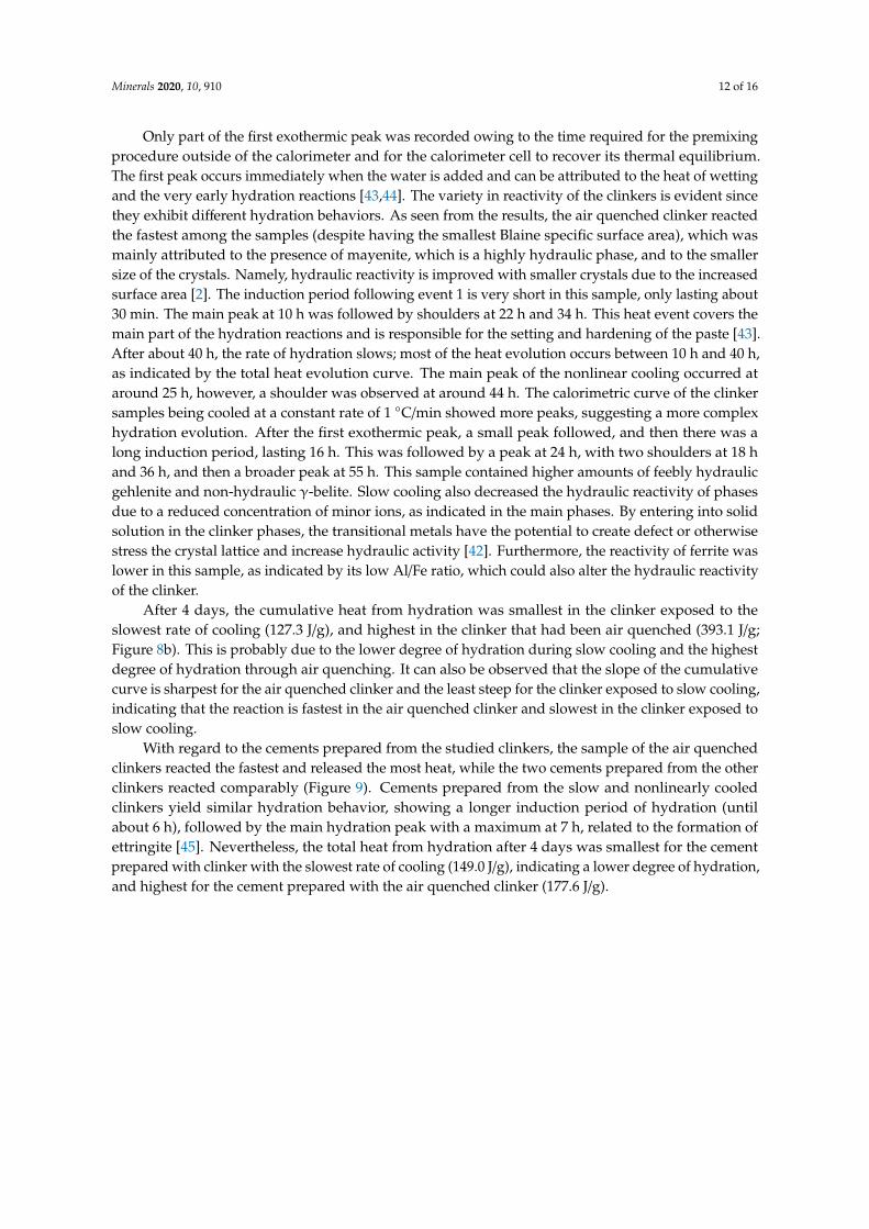
Figure 8. Hydration heat flow (a) and the development of cumulative heat of hydration (b) for the
cement clinkers under varying cooling regimes.
Only part of the first exothermic peak was recorded owing to the time required for the
premixing procedure outside of the calorimeter and for the calorimeter cell to recover its thermal
equilibrium. The first peak occurs immediately when the water is added and can be attributed to
the heat of wetting and the very early hydration reactions [43,44]. The variety in reactivity of the
clinkers is evident since they exhibit different hydration behaviors. As seen from the results, the air
quenched clinker reacted the fastest among the samples (despite having the smallest Blaine specific
surface area), which was mainly attributed to the presence of mayenite, which is a highly hydraulic
phase, and to the smaller size of the crystals. Namely, hydraulic reactivity is improved with smaller
crystals due to the increased surface area [2]. The induction period following event 1 is very short in
this sample, only lasting about 30 min. The main peak at 10 h was followed by shoulders at 22 h
and 34 h. This heat event covers the main part of the hydration reactions and is responsible for the
setting and hardening of the paste [43]. After about 40 h, the rate of hydration slows; most of the
heat evolution occurs between 10 h and 40 h, as indicated by the total heat evolution curve. The
main peak of the nonlinear cooling occurred at around 25 h, however, a shoulder was observed at
around 44 h. The calorimetric curve of the clinker samples being cooled at a constant rate of 1
°C/min showed more peaks, suggesting a more complex hydration evolution. After the first
exothermic peak, a small peak followed, and then there was a long induction period, lasting 16 h.
This was followed by a peak at 24 h, with two shoulders at 18 h and 36 h, and then a broader peak
at 55 h. This sample contained higher amounts of feebly hydraulic gehlenite and non-hydraulic γ-
belite. Slow cooling also decreased the hydraulic reactivity of phases due to a reduced
concentration of minor ions, as indicated in the main phases. By entering into solid solution in the
clinker phases, the transitional metals have the potential to create defect or otherwise stress the
crystal lattice and increase hydraulic activity [42]. Furthermore, the reactivity of ferrite was lower in
this sample, as indicated by its low Al/Fe ratio, which could also alter the hydraulic reactivity of the
clinker.
(a) (b)
Figure 8. Hydration heat flow (a) and the development of cumulative heat of hydration (b) for thecement clinkers under varying cooling regimes.
Minerals 2020, 10, 910 12 of 16
Only part of the first exothermic peak was recorded owing to the time required for the premixingprocedure outside of the calorimeter and for the calorimeter cell to recover its thermal equilibrium.The first peak occurs immediately when the water is added and can be attributed to the heat of wettingand the very early hydration reactions [43,44]. The variety in reactivity of the clinkers is evident sincethey exhibit different hydration behaviors. As seen from the results, the air quenched clinker reactedthe fastest among the samples (despite having the smallest Blaine specific surface area), which wasmainly attributed to the presence of mayenite, which is a highly hydraulic phase, and to the smallersize of the crystals. Namely, hydraulic reactivity is improved with smaller crystals due to the increasedsurface area [2]. The induction period following event 1 is very short in this sample, only lasting about30 min. The main peak at 10 h was followed by shoulders at 22 h and 34 h. This heat event covers themain part of the hydration reactions and is responsible for the setting and hardening of the paste [43].After about 40 h, the rate of hydration slows; most of the heat evolution occurs between 10 h and 40 h,as indicated by the total heat evolution curve. The main peak of the nonlinear cooling occurred ataround 25 h, however, a shoulder was observed at around 44 h. The calorimetric curve of the clinkersamples being cooled at a constant rate of 1 ◦C/min showed more peaks, suggesting a more complexhydration evolution. After the first exothermic peak, a small peak followed, and then there was along induction period, lasting 16 h. This was followed by a peak at 24 h, with two shoulders at 18 hand 36 h, and then a broader peak at 55 h. This sample contained higher amounts of feebly hydraulicgehlenite and non-hydraulic γ-belite. Slow cooling also decreased the hydraulic reactivity of phasesdue to a reduced concentration of minor ions, as indicated in the main phases. By entering into solidsolution in the clinker phases, the transitional metals have the potential to create defect or otherwisestress the crystal lattice and increase hydraulic activity [42]. Furthermore, the reactivity of ferrite waslower in this sample, as indicated by its low Al/Fe ratio, which could also alter the hydraulic reactivityof the clinker.
After 4 days, the cumulative heat from hydration was smallest in the clinker exposed to theslowest rate of cooling (127.3 J/g), and highest in the clinker that had been air quenched (393.1 J/g;Figure 8b). This is probably due to the lower degree of hydration during slow cooling and the highestdegree of hydration through air quenching. It can also be observed that the slope of the cumulativecurve is sharpest for the air quenched clinker and the least steep for the clinker exposed to slow cooling,indicating that the reaction is fastest in the air quenched clinker and slowest in the clinker exposed toslow cooling.
With regard to the cements prepared from the studied clinkers, the sample of the air quenchedclinkers reacted the fastest and released the most heat, while the two cements prepared from the otherclinkers reacted comparably (Figure 9). Cements prepared from the slow and nonlinearly cooledclinkers yield similar hydration behavior, showing a longer induction period of hydration (untilabout 6 h), followed by the main hydration peak with a maximum at 7 h, related to the formation ofettringite [45]. Nevertheless, the total heat from hydration after 4 days was smallest for the cementprepared with clinker with the slowest rate of cooling (149.0 J/g), indicating a lower degree of hydration,and highest for the cement prepared with the air quenched clinker (177.6 J/g).

Minerals 2020, 10, 910 13 of 16
Minerals 2020, 10, x FOR PEER REVIEW 13 of 17
After 4 days, the cumulative heat from hydration was smallest in the clinker exposed to the
slowest rate of cooling (127.3 J/g), and highest in the clinker that had been air quenched (393.1 J/g;
Figure 8b). This is probably due to the lower degree of hydration during slow cooling and the
highest degree of hydration through air quenching. It can also be observed that the slope of the
cumulative curve is sharpest for the air quenched clinker and the least steep for the clinker exposed
to slow cooling, indicating that the reaction is fastest in the air quenched clinker and slowest in the
clinker exposed to slow cooling.
With regard to the cements prepared from the studied clinkers, the sample of the air quenched
clinkers reacted the fastest and released the most heat, while the two cements prepared from the
other clinkers reacted comparably (Figure 9). Cements prepared from the slow and nonlinearly
cooled clinkers yield similar hydration behavior, showing a longer induction period of hydration
(until about 6 h), followed by the main hydration peak with a maximum at 7 h, related to the
formation of ettringite [45]. Nevertheless, the total heat from hydration after 4 days was smallest for
the cement prepared with clinker with the slowest rate of cooling (149.0 J/g), indicating a lower
degree of hydration, and highest for the cement prepared with the air quenched clinker (177.6 J/g).
Figure 9. Hydration heat flow (a) and the development of cumulative heat of hydration (b) for the
cements under varying cooling regimes.
3.4. Compressive Strength
As seen from the results in Table 5, the compressive strength of cement after 7 days of curing
varied slightly according to the cooling regime under which the clinkers had been synthesized. The
highest compressive strength was observed in the cements made from the air quenched clinker,
relatively closely followed by the non-linearly cooled sample. The compressive strength of the
sample, which had been subjected to slow linear cooling, was significantly lower.
Table 5. Compressive strength (at 7 days) of cement made from clinkers exposed to varying cooling
regimes.
Compressive Strength Air Quenching Nonlinear Slow Cooling
N/mm2 18.8 ± 0.7 17.9 ± 1.2 11.5 ± 0.2
In general, the compressive strength of the studied clinkers decreased as the cooling rate
slowed. Kohl [34] compared OPC clinker cooling rates to physical cement strength tests, where
rapid to moderate cooling increased the 28-day strength. Additionally, Bullard (2015) [2] also
showed that very slow cooling of OPC clinkers decreased strength at all ages. It is interesting to
note that the sample made from the slowly cooled clinker developed low compressive strength,
despite having the highest Blaine fineness, which could be attributed to its phase composition and
(a) (b)
Figure 9. Hydration heat flow (a) and the development of cumulative heat of hydration (b) for thecements under varying cooling regimes.
3.4. Compressive Strength
As seen from the results in Table 5, the compressive strength of cement after 7 days of curing variedslightly according to the cooling regime under which the clinkers had been synthesized. The highestcompressive strength was observed in the cements made from the air quenched clinker, relativelyclosely followed by the non-linearly cooled sample. The compressive strength of the sample, which hadbeen subjected to slow linear cooling, was significantly lower.
Table 5. Compressive strength (at 7 days) of cement made from clinkers exposed to varyingcooling regimes.
Compressive Strength Air Quenching Nonlinear Slow Cooling
N/mm2 18.8 ± 0.7 17.9 ± 1.2 11.5 ± 0.2
In general, the compressive strength of the studied clinkers decreased as the cooling rate slowed.Kohl [34] compared OPC clinker cooling rates to physical cement strength tests, where rapid tomoderate cooling increased the 28-day strength. Additionally, Bullard (2015) [2] also showed thatvery slow cooling of OPC clinkers decreased strength at all ages. It is interesting to note that thesample made from the slowly cooled clinker developed low compressive strength, despite havingthe highest Blaine fineness, which could be attributed to its phase composition and microstructure.In addition to larger crystal grains, the lower compressive strength of the slowly cooled clinker samplecould, therefore, be attributed to the presence of phases with poor hydraulic properties, such asgehlenite [27,46]. On the contrary, mayenite is a highly hydraulic phase and contributed to the highercompressive strength of cement produced from clinkers, which had been air quenched or nonlinearlycooled in this study.
4. Conclusions
This contribution presents results on the influence of different cooling regimes on the mineralogyand reactivity of cement clinkers based on belite-sulfoaluminate.
Results showed that the type of cooling regime influenced the phase assemblage of clinkers aswell as the morphology and size of the main clinker phases. In addition to the three targeted mainphases (belite, calcium sulfoaluminate, and ferrite), clinkers also contained periclase, perovskite, andarcanite, as well as gehlenite and mayenite as minor phases. The ratios of mayenite and gehlenitedepended predominately on the cooling rate. Whereas the highly hydraulic mayenite was promotedby rapid cooling, the feebly hydraulic phase gehlenite was formed during slow cooling. The overall

Minerals 2020, 10, 910 14 of 16
sizes of belite grains were largest in the clinker subjected to slow linear cooling, but such an influencewas less evident in the case of calcium sulfoaluminate. Ferrite occurred as an interstitial phase, which,together with small rounded belite and angular calcium sulfoaluminate grains, formed a poikiliticmicrotexture, especially in the sample subjected to slow linear cooling.
The microstructure influenced the clinkers’ reactivity, since the air cooled clinker, which consistedof phase grains with smaller sizes overall, reacted more rapidly than those clinkers, which hadbeen cooled at slower rates. Moreover, air quenching increases the chances of other elements beingincorporated into the clinker phases, resulting in the formation of more reactive ferrite and calciumsulfoaluminate, and stabilizing β-belite. The compressive strength of cement decreased with lowercooling rates, with the air quenched clinker exhibiting the highest value of compressive strength at7 days.
The overall results of the study indicated that within the belite-calcium sulfoaluminate-ferritesystem, among the three cooling regimes studied, air quenching resulted in the most reactive cementclinker and in a higher compressive strength of cement. Highly reactive mayenite was formed withrapid cooling of the clinker, whilst the formation of non-hydraulic (γ-belite) or poorly hydraulic(gehlenite) phases, were respectively diminished or prevented.
Author Contributions: Conceptualization, S.D. and L.Ž.; methodology, S.D., A.I. and L.Ž.; analysis, K.Š., L.Ž.,S.D., K.N., M.B.; writing—original draft preparation, S.D.; writing—review and editing, S.D., L.Ž., A.I., K.Š.;funding acquisition, S.D., L.Ž., A.I. All authors have read and agreed to the published version of the manuscript.
Funding: Project No. C3330-17-529035 "Raziskovalci-2.0-ZAG-529035" was granted by the Ministry of Education,Science and Sport of the Republic of Slovenia. The investment is co-financed by the Republic of Slovenia, Ministryof Education, Science and Sport and the European Regional Development Fund.
Acknowledgments: The Metrology Institute of the Republic of Slovenia is acknowledged for the use of XRF.
Conflicts of Interest: The authors declare no conflict of interest.
References
1. Ono, Y. Microscopical Observations of Clinker for the Estimation of Burning Condition. Grindability,and Hydraulic Activity. In Proceedings of the Third International Conference on Cement Microscopy,International Cement Microscopy Association, Houston, TX, USA, 19–21 March 1981; pp. 198–210.
2. Bullard, R.A. Effect of Cooling Rates on Mineralization in Portland Cement Clinker. Ph.D. Thesis, Universityof Missouri-Columbia, Columbia, MO, USA, 2015.
3. Telschow, S.; Dam-Johansen, K.; Jappe Frandsen, F.; Wedel, S.; Theisen, K. Clinker Burning Kinetics andMechanism. Ph.D. Thesis, Technical University of Denmark, Lyngby, Denmark, 2012.
4. Stanek, T.; Sulovský, P. The Impact of Basic Minor Oxides on the Clinker Formation. Mater. Sci. Forum 2017,908, 3–9. [CrossRef]
5. Ward, G.W. Effect of heat treatment and cooling rate on the microscopic structure of portland cement clinker.J. Res. Natl. Bur. Stan. 1941, 26, 49. [CrossRef]
6. Hong, H.; Fu, Z.; Min, X. Effect of cooling performance on the mineralogical character of Portland cementclinker. Cem. Concr. Res. 2001, 31, 287–290. [CrossRef]
7. Sazonova, N.A.; Skripnikova, N.K. Using the low-temperature plasma in cement production. J. Phys.Conf. Ser. 2015, 652, 012063. [CrossRef]
8. Maki, I. Processing Conditions of Portland Cement Clinker as Viewed from the Fine Textures of theConstituent Minerals. Ceram. Trans. 1994, 40, 3–17.
9. Ichikawa, M.; Ikeda, S.; Komukai, Y. Effect of cooling rate and Na20 content on the character of the interstitialmaterials in portland cement clinker. Cem. Concr. Res. 1994, 24, 5.
10. Fukuda, K.; Maki, I.; Ikeda, S.; Ito, S. Microtextures Formed by the Remelting Reaction in Belite Crystals.J. Am. Ceram. Soc. 1993, 76, 2942–2944. [CrossRef]
11. Martín-Sedeño, M.C.; Cuberos, A.J.M.; De la Torre, Á.G.; Álvarez-Pinazo, G.; Ordónez, L.M.; Gateshki, M.;Aranda, M.A.G. Aluminum-rich belite sulfoaluminate cements: Clinkering and early age hydration.Cem. Concr. Res. 2010, 40, 359–369. [CrossRef]

Minerals 2020, 10, 910 15 of 16
12. Ma, B.; Li, X.; Shen, X.; Mao, Y.; Huang, H. Enhancing the addition of fly ash from thermal power plants inactivated high belite sulfoaluminate cement. Constr. Build. Mater. 2014, 52, 261–266. [CrossRef]
13. Bullerjahn, F.; Schmitt, D.; Ben Haha, M. Effect of raw mix design and of clinkering process on the formationand mineralogical composition of (ternesite) belite calcium sulphoaluminate ferrite clinker. Cem. Concr. Res.2014, 59, 87–95. [CrossRef]
14. De la Torre, Á.G.; Cuberos, A.J.M.; Álvarez-Pinazo, G.; Cuesta, A.; Aranda, M.A.G. In situ powder diffractionstudy of belite sulfoaluminate clinkering. J. Synchrotron Rad. 2011, 18, 506–514. [CrossRef]
15. Ma, S.; Snellings, R.; Li, X.; Shen, X.; Scrivener, K.L. Alite-ye’elimite cement: Synthesis and mineralogicalanalysis. Cem. Concr. Res. 2013, 45, 15–20. [CrossRef]
16. Quillin, K. Performance of belite–sulfoaluminate cements. Cem. Concr. Res. 2001, 31, 1341–1349. [CrossRef]17. Gartner, E.; Sui, T. Alternative cement clinkers. Cem. Concr. Res. 2018, 114, 27–39. [CrossRef]18. Liu, G.Q.; Yang, Q.X.; Jiang, L.; Xue, P.; Zhang, X.L.; Han, F.L. Sintering characteristics of BCSAF cement
clinker with added wastes from production of manganese and magnesium metals. Adv. Cem. Res. 2017, 1–9.[CrossRef]
19. Cuberos, A.J.M.; De la Torre, Á.G.; Álvarez-Pinazo, G.; Martín-Sedeño, M.C.; Schollbach, K.;Pöllmann, H.; Aranda, M.A.G. Active Iron-Rich Belite Sulfoaluminate Cements: Clinkering and Hydration.Environ. Sci. Technol. 2010, 44, 6855–6862. [CrossRef] [PubMed]
20. Aranda, M.A.G.; Cuberos, A.J.M.; Cuesta, A.; Alvarez-Pinazo, G.; De la Torre, A.G.; Schollbach, K.;Pollmann, H. Hydrating behaviour of activated belite sulfoaluminate cements. In Proceedings of the 13thInternational Congress on the Chemistry of Cement, Madrid, Spain, 3–8 July 2011.
21. Senff, L.; Castela, A.; Hajjaji, W.; Hotza, D.; Labrincha, J.A. Formulations of sulfobelite cement through designof experiments. Constr. Build. Mater. 2011, 25, 3410–3416. [CrossRef]
22. Da Costa, E.B.; Rodríguez, E.D.; Bernal, S.A.; Provis, J.L.; Gobbo, L.A.; Kirchheim, A.P. Productionand hydration of calcium sulfoaluminate-belite cements derived from aluminium anodising sludge.Constr. Build. Mater. 2016, 122, 373–383. [CrossRef]
23. Dieneman, W.; Schmitt, D.; Bullerjahn, F.; Ben Haha, M. Belite-Calciumsulfoaluminate-Ternesite (BCT)-Anew low-carbon clinker Technology. Cem. Int. 2013, 11, 100–109.
24. Arjunan, P.; Silsbee, M.R.; Della, M. Roy Sulfoaluminate-belite cement from low-calcium fly ash andsulfur-rich and other industrial by-products. Cem. Concr. Res. 1999, 29, 1305–1311. [CrossRef]
25. Chen, I.A.; Juenger, M.C.G. Synthesis and hydration of calcium sulfoaluminate-belite cements with variedphase compositions. J. Mater. Sci. 2011, 46, 2568–2577. [CrossRef]
26. Álvarez-Pinazo, G.; Cuesta, A.; García-Maté, M.; Santacruz, I.; Losilla, E.R.; la Torre, A.G.D.; León-Reina, L.;Aranda, M.A.G. Rietveld quantitative phase analysis of Yeelimite-containing cements. Cem. Concr. Res. 2012,42, 960–971. [CrossRef]
27. Wang, W.; Wang, X.; Zhu, J.; Wang, P.; Ma, C. Experimental Investigation and Modeling of SulfoaluminateCement Preparation Using Desulfurization Gypsum and Red Mud. Ind. Eng. Chem. Res. 2013, 52, 1261–1266.[CrossRef]
28. Borštnar, M.; Daneu, N.; Dolenec, S. Phase development and hydration kinetics of belite-calciumsulfoaluminate cements at different curing temperatures. Ceram. Int. 2020. [CrossRef]
29. Taylor, H.F.W. Cement Chemistry, 2nd ed.; T. Telford: London, UK, 1997; ISBN 978-0-7277-2592-9.30. Cuesta, A.; De la Torre, A.G.; Losilla, E.R.; Peterson, V.K.; Rejmak, P.; Ayuela, A.; Frontera, C.; Aranda, M.A.G.
Structure, Atomistic Simulations, and Phase Transition of Stoichiometric Yeelimite. Chem. Mater. 2013, 25,1680–1687. [CrossRef]
31. Hargis, C.W.; Moon, J.; Lothenbach, B.; Winnefeld, F.; Wenk, H.-R.; Monteiro, P.J.M. Calcium SulfoaluminateSodalite (Ca4Al6O12SO4) Crystal Structure Evaluation and Bulk Modulus Determination. J. Am. Ceram. Soc.2014, 97, 892–898. [CrossRef]
32. Pedersen, M.T.; Jensen, F.; Skibsted, J. Structural Investigation of Ye’elimite, Ca4Al6O12SO4, by 27Al MASand MQMAS NMR at Different Magnetic Fields. J. Phys. Chem. C 2018, 122, 12077–12089. [CrossRef]
33. Muzhen, S.; Junan d Zongdao, W.; Xiaoxin, L. Research on the chemical composition and microstructures ofsulho-aluminate cement clinker.
34. Kohl, R.F. Effects of Cooling Rate; Portland Cement Association: Skokie, IL, USA, 1979; Kiln Paper No. 24; pp. 1–23.35. Kurdowski, W. Cement and Concrete Chemistry; Springer: Cham, The Netherlands, 2014;
ISBN 978-94-007-7944-0.

Minerals 2020, 10, 910 16 of 16
36. Cuesta, A.; Aranda, M.A.G.; Sanz, J.; de la Torre, Á.G.; Losilla, E.R. Mechanism of stabilization of dicalciumsilicate solid solution with aluminium. Dalton Trans. 2014, 43, 2176–2182. [CrossRef]
37. Moteki, T.; Chaikittisilp, W.; Shimojima, A.; Okubo, T. Silica Sodalite without Occluded Organic Matters byTopotactic Conversion of Lamellar Precursor. J. Am. Chem. Soc. 2008, 130, 15780. [CrossRef]
38. Fortes, G.M.; Lourenço, R.R.; Montini, M.; Gallo, J.B.; Rodrigues, J.D.A. Synthesis and MechanicalCharacterization of Iron Oxide Rich Sulfobelite Cements Prepared Using Bauxite Residue. Mat. Res.2016, 19, 276–284. [CrossRef]
39. Idrissi, M.; Diouri, A.; Damidot, D.; Greneche, J.M.; Talbi, M.A.; Taibi, M. Characterisation of iron inclusionduring the formation of calcium sulfoaluminate phase. Cem. Concr. Res. 2010, 40, 1314–1319. [CrossRef]
40. Gartner, E.M.; Young, J.F.; Damidot, D.A.; Jawed, I. Hydration of Portland cement. In Structure and Performanceof Cements, 2nd ed.; Bensted, J., Barnes, P., Eds.; Spon Press: London, UK, 2002; pp. 83–84.
41. Odigure, J.O. Kinetic modelling of cement raw mix containing iron particles and clinker microstructure.Cem. Concr. Res. 1996, 26, 1435–1442. [CrossRef]
42. Moir, G.K.; Glasser, F.P. Mineralisers, modifiers and activators in the clinkering process, Mineralisers,modifiers and activators in the clinkering process. In Proceedings of the 9th International Congress on theChemistry of Cement, Delhi, India, 23–28 November 1992; Volume 1, pp. 125–152.
43. Winnefeld, F.; Barlag, S. Calorimetric and thermogravimetric study on the influence of calcium sulfate on thehydration of ye’elimite. J. Therm. Anal. Calorim. 2010, 101, 949–957. [CrossRef]
44. Shen, Y.; Chen, X.; Zhang, W.; Li, X. Effect of ternesite on the hydration and properties of calciumsulfoaluminate cement. J. Therm. Anal. Calorim. 2019, 136, 687–695. [CrossRef]
45. Winnefeld, F.; Martin, L.H.J.; Müller, C.J.; Lothenbach, B. Using gypsum to control hydration kinetics of CSAcements. Constr. Build. Mater. 2017, 155, 154–163. [CrossRef]
46. West, A.R. Solid State Chemistry and Its Applications; John Wiley and Sons, Inc.: Hoboken, NJ, USA, 2014; p. 584.
Publisher’s Note: MDPI stays neutral with regard to jurisdictional claims in published maps and institutionalaffiliations.
© 2020 by the authors. Licensee MDPI, Basel, Switzerland. This article is an open accessarticle distributed under the terms and conditions of the Creative Commons Attribution(CC BY) license (http://creativecommons.org/licenses/by/4.0/).