e-class - mercedes-benz usa · pdf fileour company and staff congratulate you on the purchase...
TRANSCRIPT

E-ClassSedanOperator’s Manual
212_AKB; 2; 41, en-USd2ureepe, Version: 2.11.8.1
2009-07-17T09:14:21+02:00 - Seite 1
SymbolsTrademarks:RBabySmartTM is a trademark of Siemens
Automotive Corp.RBluetooth® is a registered trademark of
Bluetooth SIG Inc.RHomeLink® is a registered trademark of
Prince, a Johnson Controls Company.RPRE-SAFE® is a registered trademark of
Daimler.RSIRIUS and related marks are trademarks
of SIRIUS XM Radio Inc.The following symbols are found in thisOperator’s Manual:
G Warning!Warning notices draw your attention tohazards that may endanger your health or life,or the health or life of others.
! Highlights hazards that may result indamage to your vehicle.
i Helpful hints or further information youmay find useful.
X This symbol points to instructionsfor you to follow.
X A number of these symbolsappearing in succession indicatesa multiple-step procedure.
Y page This symbol tells you where to lookfor further information on a topic.
YY This continuation symbol marks awarning or procedure which iscontinued on the next page.
Display Text in displays, such as the controlsystem, are printed in the typeshown here.
212_AKB; 2; 41, en-USd2ureepe, Version: 2.11.8.1
2009-07-17T09:14:21+02:00 - Seite 2

Our company and staff congratulate you onthe purchase of your new Mercedes-Benz.Your selection of our product is ademonstration of your trust in our companyname. Furthermore, it exemplifies your desireto own an automobile that will be as easy aspossible to operate and will provide years ofservice.Your Mercedes-Benz represents the efforts ofmany skilled engineers and craftsmen. Tohelp assure your driving pleasure, and alsothe safety of you and your passengers, we askyou to make a small investment of time:RPlease read this manual carefully, then
return it to your vehicle where it will behandy for your reference.RPlease follow the recommendations
contained in this manual. They aredesigned to acquaint you with theoperation of your Mercedes-Benz.RPlease pay attention to the warnings and
cautions contained in this manual. They aredesigned to help improve the safety of thevehicle operator and occupants.
We extend our best wishes for many miles ofsafe, pleasurable driving.Mercedes-Benz USA, LLCA Daimler Company
2125845881 É21258458817ËÍ
212_AKB; 2; 41, en-USd2ureepe, Version: 2.11.8.1
2009-07-17T09:14:21+02:00 - Seite 1

212_AKB; 2; 41, en-USd2ureepe, Version: 2.11.8.1
2009-07-17T09:14:21+02:00 - Seite 2

Index ....................................................... 4
Introduction ......................................... 20
At a glance ........................................... 25
Safety and security ............................. 35
Controls in detail ................................. 75
Operation ........................................... 219
Practical hints ................................... 267
Technical data ................................... 345
Contents 3
212_AKB; 2; 41, en-USd2ureepe, Version: 2.11.8.1
2009-07-17T09:14:21+02:00 - Seite 3

1, 2, 3 ...4-ETS
see ETS/4-ETS 4MATIC
see All-wheel drive (4MATIC)
AABS (Antilock Brake System) ............. 62
Indicator lamp ................................ 305Messages in the multifunctiondisplay ................................... 288, 289
Accessory weight .............................. 249Accidents ........................................... 112
Air bags ........................................... 37Emergency calls (Tele Aid) ............. 208NECK-PRO active front headrestraints ........................................ 54
Active Bi-Xenon headlampssee Headlamps
Adaptive Brake .................................... 64Adaptive Highbeam Assist ............... 100
Switching on or off ......................... 142AdBlue® ...................................... 333, 364
Refilling ......................................... 334Additives
Engine oil ....................................... 362Gasoline ......................................... 364
Address change ................................... 21Advanced Tire PressureMonitoring System (AdvancedTPMS) ................................................. 233
Messages in the multifunctiondisplay ........................................... 285
Air bags ................................................ 37Emergency call upon deployment . . 208Front, driver and passenger ............. 40Front passenger front air bag offindicator lamp (Canadaonly) ........................................ 46, 313Front passenger front air bag offindicator lamp (USA only) ........ 43, 314Knee bag .......................................... 40Messages in the multifunctiondisplay ........................................... 276OCS (Occupant ClassificationSystem) ........................................... 43
Pelvis ............................................... 42Safety guidelines ............................. 39Side impact ...................................... 41Window curtain ................................ 42
Air conditioning refrigerant andlubricant ............................................. 362Air distribution .................................. 189Air filter .............................................. 299AIRMATIC
Damping system ............................ 163Introduction ................................... 163Messages in the multifunctiondisplay ........................................... 292Vehicle level control ...................... 163
Air pressuresee Tire inflation pressure
Air pressure (tires) ............................ 250Air pump (electric) ............................ 327Air recirculation mode ...................... 190Air volume .......................................... 189Alarm system
see Anti-theft systems Alignment bolt (vehicle tool kit) ...... 326All-wheel drive (4MATIC) .................. 161Alternator
Messages in the multifunctiondisplay ................................... 284, 297
Alternator (Technical data)see Vehicle specification
AMG adaptive sport suspensionsystem (E 63 AMG) ............................ 164AMG menu ......................................... 131Anticorrosion/antifreeze .................. 365Antilock Brake System
see ABS Anti-theft systems ............................... 71
Anti-theft alarm system ................... 72Immobilizer ...................................... 71
Aquaplaningsee Hydroplaning
Armrest, front Storage compartment .................... 202
Armrest, rear Storage compartment .................... 202
Ashtrays ............................................. 206Aspect ratio (tires) ............................ 250Assistance menu ............................... 137
4 Index
212_AKB; 2; 41, en-USd2ureepe, Version: 2.11.8.1
2009-07-17T09:14:21+02:00 - Seite 4

ATTENTION ASSIST ........................... 178Messages in the multifunctiondisplay ........................................... 292Switching on or off ......................... 138
Audio menu ........................................ 134Auto-dimming rear view mirrors ........ 95Automatic central locking .......... 80, 144Automatic climate control
see Climate control system Automatic headlamp mode ................ 98Automatic interior lighting control .. 103Automatic locking when driving ...... 144Automatic shift program .................. 120Automatic transmission ................... 114
Automatic shift program ................ 120Gear range indicator ...................... 120Gear ranges ................................... 120Gear selector lever ........................ 115Hill-start assist system .................. 160Kickdown ....................................... 119Kickdown (manual shift program) . . 124Manual shift program ..................... 122One-touch gearshifting .................. 121Program mode indicator ................ 121Program mode selector dial(E 63 AMG) ............................ 121, 123Program mode selector switch(automatic shift program) .............. 120Shifting procedure ......................... 118Steering wheel gearshift control .... 122Transmission position indicator ..... 118Transmission positions .................. 118
AUX socket ........................................ 201Axle oils .............................................. 360
BBabySmart™
Air bag deactivation system ............. 46Self-test ........................................... 47
Backrestsee Seats
Backup lamps Messages in the multifunctiondisplay ........................................... 300
Bar (air pressure unit) ....................... 250BAS (Brake Assist System) ................. 63
BAS PLUS (Brake Assist SystemPLUS) .................................................... 63Batteries, SmartKey
Checking condition .......................... 79Replacing ....................................... 317
Battery, Vehicle ................................. 336Charging ........................................ 337Jump starting ................................. 338Messages in the multifunctiondisplay ................................... 284, 297
Bead (tire) .......................................... 250Beverage holders
see Cup holders Bleeding the fuel system (dieselengine) ............................................... 333Blind Spot Assist ............................... 175
Messages in the multifunctiondisplay ........................................... 281Switching on or off ......................... 138
BlueTEC AdBlue® tank ................................. 333
Brake Assist Systemsee BAS
Brake Assist System PLUSsee BAS PLUS
Brake fluid Checking level ............................... 227Messages in the multifunctiondisplay ........................................... 289
Brake lamps Cleaning lenses ............................. 262
Brake pads Messages in the multifunctiondisplay ........................................... 287
Brakes ................................................ 254Ceramic brake system ................... 256High-performance brake system .... 256Parking brake ................................ 113Warning lamp ................................. 305
Break-in period .................................. 220Bug cover (Radiator) ......................... 224Bulbs
see Replacing bulbs
Index 5
212_AKB; 2; 41, en-USd2ureepe, Version: 2.11.8.1
2009-07-17T09:14:21+02:00 - Seite 5

CCAC (Customer Assistance Center) ... 23California retail buyers andlessees, important notice for ............. 21Calls (phone) ...................................... 135Can holders
see Cup holders Capacities and recommendedfuel/lubricants .................................. 359Cargo tie-down rings ......................... 199Carpets, cleaning .............................. 266Center console ..................................... 32Central locking
Automatic ................................ 80, 144KEYLESS-GO .................................... 77Locking/unlocking from inside ........ 81SmartKey ......................................... 76
Central locking/unlocking switch ..... 81Ceramic brake system ...................... 256Certification label .............................. 346Children in the vehicle
Air bags ........................................... 37BabySmart™ air bag deactivationsystem ............................................. 46Child safety locks (rear doors) ......... 60Child seat anchors – LATCH-type(ISOFIX) ........................................... 59Indicator lamp, front passengerfront air bag off (Canada only) ......... 46Indicator lamp, front passengerfront air bag off (USA only) .............. 43Infant and child restraint systems .... 56ISOFIX (Child seat anchors –LATCH-type) ..................................... 59OCS (Occupant ClassificationSystem) ........................................... 43Override switch ................................ 60Safety notes ..................................... 56Tether anchorage points .................. 58Top tether ........................................ 58
Child safetysee Children in the vehicle
Child seat anchors – LATCH-type(ISOFIX)
see Children in the vehicle Chrome-plated exhaust tip,cleaning .............................................. 266
Cigarette lighter ................................ 206Climate control
see Climate control system Climate control system .................... 180
Air conditioning ............................. 185Air conditioning refrigerant ............ 362Air distribution ............................... 189Air recirculation mode ................... 190Air volume ..................................... 189Automatic mode ............................ 186Deactivating system ...................... 185Front defroster .............................. 189Maximum cooling MAX COOL ........ 190Residual heat and ventilation ......... 191Temperature .................................. 186
Cockpit ................................................. 27Cold tire inflation pressure .............. 250Collapsible wheel chock ................... 270COMAND system
see separate COMAND systemoperating instructions
Combination switch .......................... 100Compass ............................................ 216Control system .................................. 126
Multifunction display ..................... 128Multifunction steering wheel ......... 126Resetting to factory settings .......... 139
Control system menus ...................... 129AMG ............................................... 131Assistance ..................................... 137Audio ............................................. 134Navi ............................................... 134Service ........................................... 138Settings ......................................... 139Telephone ...................................... 135Trip ................................................ 129
Control system submenus Convenience .................................. 145Instrument cluster ......................... 140Lighting .......................................... 141Vehicle ........................................... 144
Convenience submenu Easy-entry/exit feature .................. 145Seat belt adjustment function ....... 145
Coolant Anticorrosion/antifreeze ............... 365Capacities ...................................... 361Checking level ............................... 226
6 Index
212_AKB; 2; 41, en-USd2ureepe, Version: 2.11.8.1
2009-07-17T09:14:21+02:00 - Seite 6

Messages in the multifunctiondisplay ........................................... 295Temperature gauge ........................ 125Warning lamp ................................. 311
Corner-illuminating lamps ................ 102Replacing bulbs ............................. 319
Cruise control .................................... 146Activating ....................................... 147Canceling ....................................... 147Changing the set speed ................. 148Last stored speed .......................... 148Lever .............................................. 147Messages in the multifunctiondisplay ........................................... 279Resume function ............................ 148Setting current speed .................... 147
Cup holders ........................................ 203Curb weight ....................................... 250Customer Assistance Center (CAC) ... 23Customer Relations Department ....... 23
DDamping system ............................... 163Dashboard
see Instrument cluster Data recording ..................................... 23Daytime running lamp mode .............. 98
Switching on or off ......................... 141Deep water
see Standing water Defroster
Front (Climate control system) ...... 189Rear window .................................. 191
Delayed shut-off Exterior lamps ................................ 142Interior lighting .............................. 143
Department of Transportationsee DOT
Diesel fuelsee Fuel
Difficulties While driving .................................. 112With starting .................................. 110
Dimensions (vehicle)see Vehicle specification
Direction of rotation (tires) .............. 241
Displays DISTRONIC PLUS ........................... 151Maintenance service indicator ....... 258Messages in the multifunctiondisplay ........................................... 272Multifunction display ..................... 128Symbol messages .......................... 287Text messages ............................... 274Trip computer ................................ 129Vehicle status message memory . . . 139Vehicle system settings ................. 139
DISTRONIC PLUS ............................... 149Cleaning system sensors ............... 263Displaying the distance graphic ..... 152Displays in the multifunctiondisplay ........................................... 151Distance warning lamp .......... 151, 309Driving ........................................... 154Driving with .................................... 157Lever .............................................. 153Messages in the multifunctiondisplay ........................................... 280Resume function ............................ 156Sensor cover .................................. 263Speed settings ............................... 155Stopping ........................................ 155
Door control panel .............................. 34Door handles ........................................ 34Doors
Child safety locks ............................ 60Locking/unlocking (KEYLESS-GO) ... 77Locking/unlocking (SmartKey) ........ 76Messages in the multifunctiondisplay ........................................... 293Opening from inside ......................... 80Remote door lock (Tele Aid) ........... 212Remote door unlock (Tele Aid) ....... 211Unlocking (Mechanical key) ........... 314
DOT (Department ofTransportation) .................................. 250Drinking and driving ......................... 254Drive-dynamic multicontour seat ...... 91Driving
Abroad ........................................... 257Hydroplaning ................................. 257Instructions ........................... 109, 254In winter ........................................ 253Problems ....................................... 112
Index 7
212_AKB; 2; 41, en-USd2ureepe, Version: 2.11.8.1
2009-07-17T09:14:21+02:00 - Seite 7

RACE START (E 63 AMG) ............... 159Safety systems ................................ 61Systems ......................................... 146Through standing water ................. 257With DISTRONIC PLUS ................... 157
Driving and parking Safety notes .................................. 109
Driving off .................................. 111, 257Driving safety systems ....................... 61
ABS .................................................. 62Adaptive Brake ................................ 64BAS .................................................. 63BAS PLUS ........................................ 63EBP .................................................. 64ESC .................................................. 65ETS/4-ETS ....................................... 65PRE-SAFE® Brake ............................. 69
Driving systems AIRMATIC (except E 63 AMG) ........ 163All-wheel drive (4MATIC) ................ 161AMG adaptive sport suspensionsystem (E 63 AMG) ........................ 164ATTENTION ASSIST ........................ 178Blind Spot Assist ............................ 175Cruise control ................................ 146DISTRONIC PLUS ........................... 149Hill-start assist system .................. 160HOLD function ............................... 161Lane Keeping Assist ...................... 177Night View Assist Plus ................... 172Parking Guidance ........................... 168Parktronic system .......................... 165RACE START (E 63 AMG) ............... 159Rear view camera .......................... 171
Driving tips, automatictransmission ...................................... 119
EEasy-entry/exit feature .............. 93, 145EBP (Electronic BrakeProportioning) ...................................... 64Electrical system
Improper work on ormodifications ................................... 22Power outlets ................................. 207
Electrical system (Technical data)see Vehicle specification
Electronic Stability Controlsee ESC
Electronic Traction Systemsee ETS/4-ETS
Emergency, in case of First aid kit ..................................... 268Flat tire .......................................... 323Hazard warning flasher .................. 101Roadside Assistance ................ 21, 210Towing the vehicle ......................... 340
Emergency calls Tele Aid .......................................... 208
Emergency operations Remote door lock (Tele Aid) ........... 212Remote door unlock (Tele Aid) ....... 211Trunk lid, emergency release ........... 84
Emergency Tensioning Devicesee ETD
Emission control ............................... 258Information label ............................ 347System warranties ........................... 20
Engine Break-in recommendations ............ 220Cleaning ......................................... 261Compartment ................................ 223Malfunction indicator lamp ............ 310Messages in the multifunctiondisplay ........................................... 295Number .......................................... 347Starting .......................................... 109Turning off ..................................... 113
Engine (Technical data)see Vehicle specification
Engine compartment Radiator ......................................... 224
Engine coolantsee Coolant
Engine oil Adding ........................................... 225Additives ........................................ 362Checking level ............................... 224Consumption ................................. 224Messages in the multifunctiondisplay ........................................... 298Oil dipstick ..................................... 225Recommended engine oils and oilfilter ............................................... 361
8 Index
212_AKB; 2; 41, en-USd2ureepe, Version: 2.11.8.1
2009-07-17T09:14:21+02:00 - Seite 8
ESC (Electronic Stability Control) ...... 65ETS/4-ETS ....................................... 65Messages in the multifunctiondisplay ........................... 288, 289, 290Warning lamp ................................. 309
ETD (Emergency TensioningDevice) ................................................. 52
Safety guidelines ............................. 39ETS/4-ETS (Electronic TractionSystem) ................................................ 65Express operation
Panorama roof ............................... 195Power windows .............................. 105Tilt/sliding sunroof ........................ 192
Exterior lamp switch ........................... 97Exterior rear view mirrors .................. 95
Parking position ............................... 95Exterior view of vehicle ...................... 26
FFastening the seat belts ..................... 50First aid kit ......................................... 268Flat tire ............................................... 323
Lowering the vehicle ...................... 328Mounting the spare wheel ............. 323Preparing the vehicle ..................... 323Spare wheel ........................... 323, 358TIREFIT (tire repair kit) ................... 329
Floormats ........................................... 217Fluids
Automatic transmission fluid ......... 360Brake fluid ..................................... 361Capacities ...................................... 359Engine coolant ............................... 361Engine oil ....................................... 360Power steering fluid ....................... 360Washer and headlamp cleaningsystem ........................................... 361
Fog lamps ............................................. 99Messages in the multifunctiondisplay ................................... 300, 302
Four-wheel drivesee All-wheel drive (4MATIC)
Front air bagssee Air bags
Front axle oil ...................................... 360
Front lampssee Headlamps
Front passenger front air bag ............ 40Messages in the multifunctiondisplay ........................................... 276
Front passenger front air bag offindicator lamp (Canada only) ..... 46, 313Front passenger front air bag offindicator lamp (USA only) .......... 43, 314Fuel ..................................................... 220
Additives ........................................ 364Capacity, fuel tank ......................... 361Diesel fuel ...................................... 363Drive sensibly–safe fuel ................. 254Fuel consumption statistics ........... 130Fuel filler flap and cap ................... 222Fuel tank reserve warning lamp ..... 310Premium unleaded gasoline ........... 362Refueling ........................................ 220Requirements ................................ 363
Fuel filler flap ..................................... 222Opening manually .......................... 316
Fuel gauge ......................................... 126Fuels, coolants, lubricants etc. ........ 359Fuel system, bleeding (dieselengine) ............................................... 333Fuel tank
Capacity ........................................ 361Fuel filler flap and cap ................... 222Refueling ........................................ 220
Fuses .................................................. 343
GGarage door opener .................... 33, 212Gasoline
see Fuel GAWR (Gross Axle Weight Rating) ... 250Gear range ......................................... 120
Indicator ........................................ 120Limiting .......................................... 122Shifting into optimal ...................... 122
Gear selector lever ............................ 115Cleaning ......................................... 265Gearshift pattern ........................... 115Shifting procedure ......................... 118Transmission position indicator ..... 118Transmission positions .................. 118
Index 9
212_AKB; 2; 41, en-USd2ureepe, Version: 2.11.8.1
2009-07-17T09:14:21+02:00 - Seite 9

Generatorsee Alternator
Global locking/unlockingsee Key, SmartKey
Glove box ........................................... 201Gross Axle Weight Rating
see GAWR Gross Vehicle Weight
see GVW Gross Vehicle Weight Rating
see GVWR GVW (Gross Vehicle Weight) ............ 250GVWR (Gross Vehicle WeightRating) ................................................ 250
HHalogen headlamps
see Headlamps Hard plastic trim items, cleaning .... 265Hazard warning flasher .................... 101Headlamp cleaning system .............. 102Headlamps
Active Bi-Xenon headlamps ............. 97Adaptive Highbeam Assist ............. 100Automatic headlamp mode .............. 98Bi-Xenon .................................. 97, 319Cleaning lenses ............................. 262Cleaning system ............................ 102Daytime running lamp mode ............ 98Delayed shut-off ............................ 142Halogen ......................................... 319High-beam flasher ......................... 101High-beam headlamps ................... 100Low-beam headlamps ...................... 98Messages in the multifunctiondisplay ........................................... 299Replacing bulbs ............................. 318Switch .............................................. 97
Headliner and shelf below rearwindow, cleaning and care of .......... 266Head restraints .................................... 87
Adjustment ................................ 87, 89Comfort head restraint .................... 89Folding back .................................... 89NECK-PRO active front headrestraints ......................................... 54Rear seat head restraints ................. 89
Heated steering wheel ........................ 94Height adjustment
Seat belt outlet ................................ 51Seats ............................................... 87Vehicle level control ...................... 163
High-beam flasher ............................. 101High-beam headlamps .............. 100, 319
Adaptive Highbeam Assist ............. 100Indicator lamp .................................. 29Replacing bulbs ............................. 319
High-performance brake system ..... 256Hill-start assist system ..................... 160HOLD function ................................... 161Hood ................................................... 223
Messages in the multifunctiondisplay ........................................... 293
Hydroplaning ..................................... 257
IIdentification labels .......................... 346Identification number, vehicle(VIN) ................................................... 346Ignition ................................... 85, 86, 110Immobilizer .......................................... 71Indicator lamps
see Lamps, indicator and warning Infant and child restraint systems
see Children in the vehicle Inflation pressure
see Tires, Inflation pressure Inside door handle .............................. 80Instrument cluster ...................... 28, 125
Illumination .................................... 125Lamps ............................................ 304Multifunction display ..................... 128
Instrument lightingsee Instrument cluster, Illumination
Instrument panelsee Instrument cluster
Instruments and controlssee Cockpit
Interior lighting Delayed shut-off ............................ 143Emergency lighting ........................ 103Front .............................................. 103Front reading lamps ....................... 103
10 Index
212_AKB; 2; 41, en-USd2ureepe, Version: 2.11.8.1
2009-07-17T09:14:21+02:00 - Seite 10
Rear ............................................... 104Rear reading lamps ........................ 104
Interior rear view mirror ..................... 94Auto-dimming rear view mirrors ....... 95
Interior storage spacessee Storage compartments
Intermittent wiping ........................... 104Rain sensor .................................... 104
IR emitter Replacing bulbs ............................. 319
ISOFIX (Child seat anchors –LATCH-type)
see Children in the vehicle
JJack ..................................................... 270Jump starting ..................................... 338
KKey, Mechanical
Loss of ............................................. 79Replacing ......................................... 80Unlocking/locking manually .......... 314Valet locking .................................... 85
Key, SmartKey Battery check lamp .......................... 79Checking batteries ........................... 79Factory setting ........................... 77, 79Global locking (KEYLESS-GO) .................................................. 79Global locking (SmartKey) ................ 77Global unlocking (KEYLESS-GO) .................................................. 79Global unlocking(SmartKey) ....................................... 77Important notes on KEYLESS-GO ..... 78Locking/unlocking ........................... 76Loss of ............................................. 79Messages in the multifunctiondisplay ........................................... 293Opening, trunk ................................. 82Opening and closing the powertilt/sliding sunroof or thepanorama roof ............................... 107Opening and closing the windows . 107Remote control ................................ 76
Replacing ......................................... 80Replacing batteries ........................ 317Restoring to factory setting ....... 77, 79Selective setting ........................ 77, 79Starter switch positions ................... 85
KEYLESS-GO Starter switch positions ................... 86
Kickdown ........................................... 119Kickdown (manual shift program) ... 124Kilopascal (air pressure unit) ........... 250Knee bag .............................................. 40
LLabels
Certification ................................... 346Emission control information ......... 347Tire and Loading Informationplacard ........................................... 237Tire inflation pressure .................... 230
Lamps, exterior Exterior lamp switch ........................ 97Front .............................................. 319Messages in the multifunctiondisplay ........................................... 299Switching on/off .............................. 97
Lamps, indicator and warning ABS .......................................... 29, 305Adaptive Highbeam Assist ............. 100Brakes ........................................... 305Coolant .......................................... 311Distance warning lamp .......... 151, 309Engine malfunction ........................ 310ESC .......................................... 29, 309ESC OFF ........................................ 308Fog lamps ........................................ 99Front passenger front air bag off(Canada only) .......................... 46, 313Front passenger front air bag off(USA only) ................................ 43, 314Fuel tank reserve ........................... 310High-beam headlamps ............. 29, 100Instrument cluster ......................... 304Low-beam headlamps ................ 30, 98Low tire pressure/TPMSmalfunction telltale ........................ 312Seat belt telltale ................ 29, 52, 307
Index 11
212_AKB; 2; 41, en-USd2ureepe, Version: 2.11.8.1
2009-07-17T09:14:21+02:00 - Seite 11
SRS .......................................... 36, 308Turn signals ..................................... 29
Lane Keeping Assist .......................... 177Messages in the multifunctiondisplay ........................................... 283Switching on or off ......................... 138
LATCH-type child seat anchors (ISOFIX)see Children in the vehicle
License plate lamps Messages in the multifunctiondisplay ........................................... 301
Light alloy wheels, cleaning ............. 265Lighter
see Cigarette lighter Lighting ................................................ 97
Daytime running lamp mode ............ 98Exterior ............................................ 97Interior ........................................... 103
Limp-home mode .............................. 124Load index (tires) ...................... 246, 250Loading
see Vehicle loading Locator lighting ................................. 142Locking the vehicle
KEYLESS-GO .................................... 77Manually ........................................ 315SmartKey ......................................... 76
Loss of Key .................................................. 79Service and Warranty Informationbooklet .......................................... 346
Low-beam headlamps ......................... 98Exterior lamp switch ........................ 97Indicator lamp .................................. 30Replacing bulbs ............................. 319Switching on .................................... 98
Lubricants .......................................... 359Lumbar support ................................... 89
MMaintenance ........................................ 21Maintenance System
Service indicator display ................ 259Service indicator message ............. 258Service term exceeded .................. 259
Manual headlamp mode (Low-beam headlamps) ................................ 98
Manual shift program ....................... 122Maximum engine speed
see Vehicle specification Maximum loaded vehicle weight ..... 250Maximum load rating (tires) ............. 250Maximum permissible tireinflation pressure .............................. 251Mechanical key
see Key, Mechanical Media interface ................................. 201Memory function ................................. 96Menus
see Control system menus Minispare wheel
see Spare wheel Mirrors .................................................. 94
Auto-dimming rear view mirrors ....... 95Exterior rear view mirror parkingposition ............................................ 95Exterior rear view mirrors ................ 95Interior rear view mirror ................... 94Memory function .............................. 96Vanity mirror .................................. 205
MOExtended system ......................... 329MOExtended tires ..................... 329, 353MON (Motor Octane Number) .......... 363Motor Octane Number
see MON Multifunction display ........................ 128
Symbol messages .......................... 287Text messages ............................... 274Vehicle status messages ............... 272
Multifunction display messages ABS ....................................... 288, 289Active headlamps .......................... 299Advanced TPMS ............................. 285Air bags ......................................... 276Air filter .......................................... 299AIRMATIC ...................................... 292Alternator .............................. 284, 297ATTENTION ASSIST ........................ 292Automatictransmission .......................... 283, 284Backrests ....................................... 293Battery ................................... 284, 297Blind Spot Assist ............................ 281Brake fluid ..................................... 289
12 Index
212_AKB; 2; 41, en-USd2ureepe, Version: 2.11.8.1
2009-07-17T09:14:21+02:00 - Seite 12

Brake pads ..................................... 287Child seat ...................................... 279Coolant .......................................... 295Corner-illuminating lamps .............. 303Cruise control ................................ 279DISTRONIC PLUS ........................... 280Doors ............................................. 293EBP ................................................ 289Engine oil ....................................... 298ESC ............................... 288, 289, 290Fog lamps .............................. 300, 302Front passenger front air bag ........ 276Gas cap .......................................... 298High-beam lamps ........................... 301Hood .............................................. 293Lane Keeping Assist ...................... 283License plate lamps ....................... 301Light sensor ................................... 302Low-beam lamps ............................ 302Parking brake ................................ 289Parking lamps ................................ 301Power steering ............................... 295PRE-SAFE® .................................... 274Radar sensors ................................ 282Reserve fuel ................................... 298Reverse lamp ................................. 300Side marker lamps ......................... 300SmartKey ....................................... 293SRS ................................................ 290Tele Aid .......................................... 290Tire inflation pressure ............ 284, 304Tire pressure monitor .................... 285Tires ...................................... 284, 304Trunk ............................................. 293Turn signals ................................... 303Washer fluid ................................... 294
Multifunction steering wheel Adjustment ...................................... 93Buttons .......................................... 126Cleaning ......................................... 265Easy-entry/exit feature ........... 93, 145Gearshift control ............................ 122Heating ............................................ 94Memory function .............................. 96Overview .......................................... 30
NNavigation system
see Separate operating instructions Navi menu .......................................... 134NECK-PRO active front headrestraints ............................................. 54
Resetting ....................................... 316Nets, parcel ....................................... 199Night View Assist Plus ...................... 172
Cleaning the windshield in front ofthe camera .................................... 263
Normal occupant weight .................. 251Number, vehicle identification(VIN) ................................................... 346
OOccupant Classification System
see OCS (Occupant ClassificationSystem)
Occupant distribution ....................... 251Occupant safety
Air bags ........................................... 37BabySmart™ .................................... 46Children and air bags ....................... 37Children in the vehicle ..................... 56Child seat anchors – LATCH-type(ISOFIX) ........................................... 59Fastening the seat belts ................... 50Front passenger front air bag offindicator lamp (Canadaonly) ........................................ 46, 313Front passenger front air bag offindicator lamp (USA only) ........ 43, 314Infant and child restraint systems .... 56Introduction ..................................... 36ISOFIX (Child seat anchors –LATCH-type) ..................................... 59OCS (Occupant ClassificationSystem) ........................................... 43PRE-SAFE® ....................................... 53Seat belts .................................. 39, 48
OCS (Occupant ClassificationSystem) ................................................ 43
Self-test ........................................... 46Odometer ........................................... 129
Index 13
212_AKB; 2; 41, en-USd2ureepe, Version: 2.11.8.1
2009-07-17T09:14:21+02:00 - Seite 13
Oil, oil levelsee Engine oil
On-board computersee Control system
One-touch gearshifting ..................... 121Operating safety .................................. 22Ornamental moldings, cleaning ....... 262Overhead control panel ...................... 33
PPaintwork, cleaning .......................... 261Paintwork code ................................. 347Panic alarm .......................................... 61Panorama roof with power tilt/sliding panel ...................................... 195
Cleaning ......................................... 265Operation ....................................... 195Roller sunblinds ............................. 194Synchronizing ................................ 196
Parcel nets ......................................... 199Parking ............................................... 113
Parking Guidance .................. 168, 170Parktronic system .......................... 165
Parking and standing lamp Replacing bulbs ............................. 319
Parking brake .................................... 113Messages in the multifunctiondisplay ........................................... 289
Parking Guidance .............................. 168Canceling ....................................... 171Detecting a parking space ............. 169Parking .......................................... 170
Parking position Exterior rear view mirrors ................ 95Transmission position .................... 118
Parktronic system Cleaning system sensors ............... 263Malfunction .................................... 168Minimum distance ......................... 167Sensor range ................................. 166Switching on/off ........................... 168System sensors ............................. 166Warning indicators ................... 27, 167
Parts service ...................................... 346
PASS AIR BAG OFF indicator lamp(Canada only)
see Front passenger front air bagoff indicator lamp (Canada only)
PASS AIR BAG OFF indicator lamp(USA only)
see Front passenger front air bagoff indicator lamp (USA only)
Passenger safetysee Occupant safety
Pedals ................................................. 254Pelvis air bags ..................................... 42Phone
see Telephone Plastic parts, cleaning ...................... 265Power assistance .............................. 254Power outlets .................................... 207Power seats
see Seats Power steering
Messages in the multifunctiondisplay ........................................... 295
Power tilt/sliding sunroof Operation ....................................... 192Synchronizing ................................ 194
Power washer .................................... 261Power windows ................................. 105
Cleaning ......................................... 264Operation ....................................... 105Rear door window, overrideswitch .............................................. 60Synchronizing ................................ 107
Practical hints ................................... 268Preglow indicator lamp ..................... 110PRE-SAFE® ............................................ 53
Messages in the multifunctiondisplay ........................................... 274
PRE-SAFE® Brake ................................. 69Activating/deactivating ................. 137Messages in the multifunctiondisplay ........................................... 274
Problems While driving .................................. 112With vehicle ..................................... 23With wipers .................................... 105
Product information ............................ 20Production options weight ............... 251
14 Index
212_AKB; 2; 41, en-USd2ureepe, Version: 2.11.8.1
2009-07-17T09:14:21+02:00 - Seite 14

Program mode selector dial (E 63 AMG) Automatic shift program ........ 121, 123
Program mode selector switch Automatic shift program ................ 120
Proximity keysee Key, SmartKey
PSI (air pressure unit) ....................... 251
RRACE START (E 63 AMG) ................... 159RACETIMER ........................................ 132Radar sensors
Messages in the multifunctiondisplay ........................................... 282Switching on or off ......................... 144
Radiator ..................................... 224, 252Radio
Selecting stations .......................... 134Radio transmitters ............................ 257Rain sensor
see Intermittent wiping Rear axle oil ....................................... 360Rear center console ashtray
see Ashtrays Rear center seat belt
Unblocking ....................................... 51Rear doors
Child safety locks ............................ 60Rear door window
Override switch ................................ 60Rear fog lamp
see Fog lamps Rear lamps
see Tail lamps Rear seat head restraints
see Head restraints Rear view camera .............................. 171
Cleaning the camera lens .............. 263Rear window defroster ..................... 191Recommended tire inflationpressure ..................................... 229, 251Refilling
AdBlue® ......................................... 334Refrigerant, air conditioning ............ 362Refueling ............................................ 220Regular checks .................................. 222
Reminder, Seat beltsee Seat belts, Telltale
Remote controlsee Key, SmartKey
Remote door lock (Tele Aid) ............. 212Remote door unlock (Tele Aid) ......... 211Replacing
Key .................................................. 80Replacing bulbs ................................. 318Reporting safety defects .................... 23Research Octane Number
see RON Reserve fuel
Messages in the multifunctiondisplay ........................................... 298Warning lamp ................................. 310
Restraint systemssee Occupant safety
Retaining hook .................................. 199Rims ........................................... 251, 353Roadside Assistance ................... 21, 210Roller sunblinds ................................. 194RON (Research Octane Number) ..... 363Roof rack ............................................ 198Rubber parts, cleaning ...................... 265Run-flat tires
see MOExtended tires
SSafety
Driving safety systems ..................... 61Occupant safety ............................... 36Reporting defects ............................ 23
Safety beltssee Seat belts
Seat belt force limiter ......................... 52Seat belts ............................................. 48
Adjustment function ........................ 51Automatic comfort-fit feature .......... 53Children in the vehicle ..................... 56Cleaning ......................................... 266Fastening ......................................... 50Height adjustment ........................... 51Proper use of ................................... 49Rear center seat .............................. 51Safety guidelines ............................. 39
Index 15
212_AKB; 2; 41, en-USd2ureepe, Version: 2.11.8.1
2009-07-17T09:14:21+02:00 - Seite 15

Safety notes ..................................... 48Telltale ............................... 29, 52, 307
Seat heating ......................................... 92Seating capacity ................................ 238Seats ..................................................... 87
Adjustment ...................................... 87Drive-dynamic multicontour seat ..... 91Easy-entry/exit feature .................... 93Heating ............................................ 92Memory function .............................. 96Messages in the multifunctiondisplay ........................................... 293Split rear seat bench ..................... 199Ventilation ....................................... 92
Securing cargo Cargo tie-down rings ...................... 199
Selective settingsee Key, SmartKey
Selector leversee Gear selector lever
Self-test BabySmart™ .................................... 47OCS (Occupant ClassificationSystem) ........................................... 46Tele Aid .......................................... 208
Servicesee Maintenance
Service, parts .................................... 346Service and warranty information ..... 20Service intervals
see Maintenance System, Serviceindicator message
Service life (tires) .............................. 242Service menu ..................................... 138Settings
Factory setting (KEYLESS-GO) ......... 79Factory setting (SmartKey) .............. 77Memory function .............................. 96Menu ............................................. 139Selective setting (KEYLESS-GO) ....... 79Selective setting (SmartKey) ............ 77
Shelf below rear window, cleaning .. 266Side impact air bags ........................... 41Side marker lamps
Cleaning lenses ............................. 262Messages in the multifunctiondisplay ........................................... 300
Sidewall (tires) .................................. 251SmartKey
see Key, SmartKey SmartKey with KEYLESS-GO
see Key, SmartKey Snow chains ...................................... 252Snow tires
see Winter tires Spare wheel ....................................... 353
Mounting ....................................... 323Storage location ............................ 271
Speedometer ....................................... 28Speed settings
Cruise control ................................ 147DISTRONIC PLUS ........................... 155Resume function ................... 148, 156
SRS Indicator lamp .................................. 29
SRS (Supplemental Restraint System) Indicator lamp ......................... 36, 308Messages in the multifunctiondisplay ........................................... 290
Standing water, driving through ...... 257Starter switch positions
KEYLESS-GO .................................... 86SmartKey ......................................... 85
Starting difficulties (engine) ............ 110Starting the engine ........................... 109Steering column
see Multifunction steering wheel,Adjustment
Steering wheelsee Multifunction steering wheel
Steering wheel gearshift control ..... 122Stolen Vehicle Recovery Services . . . 212Storage compartments ..................... 201Storing tires ....................................... 243Sunroof
see Power tilt/sliding sunroof Sunshade
Rear window .................................. 205Sun visors .................................. 204, 205Suspension tuning
see AIRMATIC
16 Index
212_AKB; 2; 41, en-USd2ureepe, Version: 2.11.8.1
2009-07-17T09:14:21+02:00 - Seite 16

TTachometer .................................. 28, 126
Overspeed range ........................... 126Tail lamps
Cleaning lenses ............................. 262Tar stains ........................................... 261Technical data
Air conditioning refrigerant ............ 362Brake fluid ..................................... 362Capacities fuels, coolants,lubricants etc. ................................ 359Coolant .......................................... 365Engine oil additives ........................ 362Engine oils ..................................... 361Fuel requirements .......................... 363Gasoline additives .......................... 364Identification labels ....................... 346Premium unleaded gasoline ........... 362Rims and tires ................................ 353Spare wheel ................................... 358Vehicle specification E 350 ............ 348Vehicle specificationE 350 4MATIC ................................ 349Vehicle specificationE 350 BlueTEC ............................... 348Vehicle specification E 550 ............ 350Vehicle specificationE 550 4MATIC ................................ 351Vehicle specification E 63 AMG ..... 352Washer and headlamp cleaningsystem ................................... 361, 367
Technical data (dimensions)see Vehicle specification
Technical data (electrical system)see Vehicle specification
Technical data (engine)see Vehicle specification
Technical data (weights)see Vehicle specification
Tele Aid ............................................... 207Emergency calls ............................. 208Information button ......................... 210Initiating an emergency callmanually ........................................ 209Messages in the multifunctiondisplay ........................................... 290Remote door lock .......................... 212
Remote door unlock ...................... 211Roadside Assistance button .......... 210Search & Send ............................... 211SOS button .................................... 209Stolen Vehicle Recovery Services . . 212System self-test ............................. 208
Telephone ............................................. 30Answering/ending a call ................ 136Hands-free microphone ................... 33Menu ............................................. 135Operation ....................................... 135Phone book .................................... 136Redialing ........................................ 137
Temperature Coolant .......................................... 125Interior temperature ...................... 186Outside .......................................... 126
Tether anchorage pointssee Children in the vehicle
Through-loading feature ................... 198Tie-down rings ................................... 199Tightening torque
Wheels ........................................... 328TIN (Tire Identification Number) ...... 251Tire and Loading Informationplacard ............................................... 237Tire and loading terminology ........... 249TIREFIT ............................................... 329Tire Identification Number
see TIN Tire inflation pressure
Checking ........................................ 231Important notes on ........................ 230Label on the inside of fuel fillerflap ................................................ 230Placard on driver’s door B-pillar ..... 237
Tire labeling ....................................... 245Tire load rating .................................. 250Tire ply composition and materialused .................................................... 251Tire pressure loss warning system . 232Tire repair kit
see TIREFIT Tires ........................................... 228, 353
Advanced Tire PressureMonitoring System (AdvancedTPMS) ............................................ 233
Index 17
212_AKB; 2; 41, en-USd2ureepe, Version: 2.11.8.1
2009-07-17T09:14:21+02:00 - Seite 17
Air pressure ................................... 229Care and maintenance ................... 242Cleaning ......................................... 243Direction of rotation, spinning ....... 241Important notes on tire inflationpressure ........................................ 230Inflation pressure ........................... 231Information placard ....................... 237Inspection ...................................... 242Labeling ......................................... 245Load index ............................. 246, 250Load rating .................................... 250Messages in the multifunctiondisplay ................................... 284, 304MOExtended .................................. 353Ply composition and materialused ............................................... 251Problems under-/overinflation ...... 231Retreads ........................................ 228Rims and tires (technical data) ...... 353Rotation ......................................... 244Service life ..................................... 242Sizes .............................................. 353Snow chains .................................. 252Speed rating .......................... 247, 251Storing ........................................... 243Temperature .......................... 230, 244Terminology ................................... 249TIREFIT (tire repair kit) ................... 329Tire Identification Number ............. 251Tire pressure loss warning system . 232TPMS low tire pressure/malfunction telltale ........................ 312Traction ................................. 244, 251Tread ............................................. 251Tread depth ........................... 242, 252Treadwear ...................................... 243Treadwear indicators ............. 242, 252Vehicle maximum load on .............. 252Wear pattern .................................. 244Winter tires ............................ 252, 353
Tire speed rating ....................... 247, 251Top tether
see Children in the vehicle Total load limit ................................... 251Towing
Towing eye bolt .............................. 341Vehicle ........................................... 340
Towing eye bolt ................................. 341Traction ...................................... 244, 251Transfer case ..................................... 124Transmission
see Automatic transmission Transmission fluid level .................... 226Transmission gear selector lever
see Gear selector lever Transmission positions .................... 118Traveling abroad ............................... 257Tread (tires) ....................................... 251Tread depth (tires) .................... 242, 252Treadwear .......................................... 243Treadwear indicators (tires) . . . . 242, 252Trip menu ........................................... 129Trunk
Closing ............................................. 82Fuse box ........................................ 343Messages in the multifunctiondisplay ........................................... 293Opening ........................................... 82Opening/closing system .................. 83Tie-down rings ............................... 199Trunk lid emergency release ............ 84Unlocking manually ....................... 315Valet locking .................................... 85
Turning off the engine ...................... 113Turn signals ....................................... 100
Cleaning lenses ............................. 262Indicator lamps ................................ 29Messages in the multifunctiondisplay ........................................... 303Replacing bulbs ............................. 319
UUniform Tire Quality GradingStandards .................................. 243, 252Units
Selecting speedometer displaymode ............................................. 141
Unleaded gasoline, premium ........... 362Unlocking the vehicle
KEYLESS-GO .................................... 77Manually ........................................ 314SmartKey ......................................... 76
Upholstery, cleaning ......................... 266Useful features .................................. 203
18 Index
212_AKB; 2; 41, en-USd2ureepe, Version: 2.11.8.1
2009-07-17T09:14:21+02:00 - Seite 18

VValet locking ........................................ 85Vehicle
Battery ........................................... 336Care ............................................... 260Control system .............................. 126Identification Number (VIN) ........... 346Locking/unlocking ........................... 76Lowering (wheel change) ............... 328Modifications and alterations,Operating safety .............................. 22Towing ........................................... 340Unlocking/locking manually .......... 314
Vehicle dimensionssee Vehicle specification
Vehicle Identification Number(VIN) ................................................... 346Vehicle jack
see Jack Vehicle level control
see AIRMATIC Vehicle lighting .................................... 97Vehicle loading
Cargo tie-down rings ...................... 199Instructions .................................... 197Load limit ....................................... 238Roof rack ....................................... 198Split rear seat bench ..................... 199Terminology ................................... 249
Vehicle maximum load on the tire ... 252Vehicle specification
E 350 ............................................. 348E 350 4MATIC ................................ 349E 350 BlueTEC ............................... 348E 550 ............................................. 350E 550 4MATIC ................................ 351E 63 AMG ...................................... 352
Vehicle status message memory . . . . 139Vehicle tool kit .................................. 268Vehicle washing
see Vehicle care Vehicle weights
see Vehicle specification
WWarning sounds
DISTRONIC PLUS ........................... 151Driver’s or passenger’s seat belt ..... 52Parking brake ................................ 289Parking Guidance ........................... 170Parktronic system .......................... 168Seat belt telltale ............................ 307
Warranty coverage ............................ 346Washer and headlamp cleaningsystem ................................................ 367Washer fluid
Messages in the multifunctiondisplay ........................................... 294Mixing ratio .................................... 367Refilling .......................................... 227
Washing the vehicle .......................... 260Wear pattern (tires) .......................... 244Weights (vehicle)
see Vehicle specification Wheel
Changing ....................................... 323Removing ....................................... 326Spare ............................................. 323Tightening torque ........................... 328
Wheels, sizes ..................................... 353Wheels, Tires and .............................. 228Window curtain air bags ..................... 42Windows
see Power windows Windows, cleaning ............................ 264Windshield
Cleaning wiper blades .................... 264Washer fluid ................................... 367Wipers ........................................... 104
Windshield wipers Replacing wiper blades .................. 322
Winter cover .............................. 224, 252Winter driving
Instructions .................................... 253Radiator cover ............................... 252Snow chains .................................. 252Tires ............................................... 252
Winter tires ................................ 252, 353Wood trims, cleaning ........................ 266
Index 19
212_AKB; 2; 41, en-USd2ureepe, Version: 2.11.8.1
2009-07-17T09:14:21+02:00 - Seite 19
Product Information
Please observe the following in your own bestinterest:We recommend using Genuine Mercedes-Benz Parts as well as conversion parts andaccessories explicitly approved by us for yourvehicle model.We have tested these parts to determine theirreliability, safety and special suitability forMercedes-Benz vehicles.We are unable to make an assessment forother products and therefore cannot be heldresponsible for them, even if in individualcases an official approval or authorization bygovernmental or other agencies should exist.Use of such parts and accessories couldadversely affect the safety, performance orreliability of your vehicle. Please do not usethem.Genuine Mercedes-Benz Parts and pre-approved conversion parts and accessoriesare available at any authorized Mercedes-Benz Center. In addition, you will receivecomprehensive information on permissibletechnical modifications and expertinstallations.
Operator’s Manual
NotesThis Operator’s Manual contains a great dealof useful information. We urge you to read itcarefully and familiarize yourself with thevehicle before driving.For your own safety and longer service life ofthe vehicle, we urge you to follow theinstructions and warnings contained in thisOperator’s Manual. Ignoring them couldresult in damage to the vehicle or personalinjury to you or others. Vehicle damagecaused by failure to follow instructions is notcovered by the Mercedes-Benz LimitedWarranty.
We continuously strive to improve ourproduct and ask for your understanding thatwe reserve the right to make changes indesign and equipment. Therefore,information, illustrations, and descriptions inthis Operator’s Manual might differ from yourvehicle.
Vehicle equipmentYour vehicle may have some or all of theequipment described in this manual.Therefore, you may find explanations foroptional equipment not installed in yourvehicle. If you have any questions aboutoperating particular equipment, anyauthorized Mercedes-Benz Center will be gladto demonstrate the proper procedures.Optional equipment is also described in thismanual, including operating instructionswherever necessary. Since they are special-order items, the descriptions and illustrationsherein may vary slightly from the actualequipment of your vehicle.If there are any equipment details that are notshown or described in this Operator’sManual, any authorized Mercedes-BenzCenter will be glad to inform you of correctcare and operating procedures. TheOperator’s Manual and Maintenance Bookletare important documents and should be keptwith the vehicle.
Service and warranty informationThe Service and Warranty Informationbooklet contains detailed information aboutthe warranties covering your Mercedes-Benz,including:RNew Vehicle Limited WarrantyREmission System WarrantyREmission Performance WarrantyRCalifornia, Connecticut, Maine,
Massachusetts, New York, Pennsylvania,
20 Introduction
212_AKB; 2; 41, en-USd2ureepe, Version: 2.11.8.1
2009-07-17T09:14:21+02:00 - Seite 20

Rhode Island, and Vermont EmissionControl System WarrantyRState Warranty Enforcement Laws (Lemon
Laws)
Important notice for California retail buyers and lessees of Mercedes-Benz automobiles
Under California law you may be entitled to areplacement of your vehicle or a refund of thepurchase price or lease price, if after areasonable number of repair attemptsMercedes-Benz USA, LLC and/or itsauthorized repair or service facilities fail to fixone or more substantial defects ormalfunctions in the vehicle that are coveredby its express warranty. During the period of18 months from original delivery of thevehicle or the accumulation of 18 000 miles(approximately 29 000 km) on the odometerof the vehicle, whichever occurs first, areasonable number of repair attempts ispresumed for a retail buyer or lessee if one ormore of the following occurs:(1) the same substantial defect or
malfunction results in a condition that islikely to cause death or serious bodilyinjury if the vehicle is driven, that defector malfunction has been subject to repairtwo or more times, and you have directlynotified Mercedes-Benz USA, LLC inwriting of the need for its repair,
(2) the same substantial defect ormalfunction of a less serious nature thancategory (1) has been subject to repairfour or more times and you have directlynotified us in writing of the need for itsrepair, or
(3) the vehicle is out of service by reason ofrepair of the same or different substantialdefects or malfunctions for a cumulativetotal of more than 30 calendar days.
Written notification should not be sent to adealer, it should be addressed to
Mercedes-Benz USA, LLCCustomer Assistance CenterOne Mercedes DriveMontvale, NJ 07645-0350
MaintenanceThe Maintenance Booklet describes all thenecessary maintenance work which shouldbe performed at regular intervals.Always have the Maintenance Booklet withyou when you take the vehicle to anauthorized Mercedes-Benz Center forservice. The service advisor will record eachservice in the booklet for you.
Roadside AssistanceThe Mercedes-Benz Roadside AssistanceProgram provides factory-trained technicalhelp in the event of a breakdown. Calls to thetoll-free Roadside Assistance number1-800-FOR-MERCedes (1-800-367-6372) (in the USA) 1-800-387-0100 (in Canada)will be answered by Mercedes-BenzCustomer Assistance Representatives24 hours a day, 365 days a year.For additional information refer to theMercedes-Benz Roadside AssistanceProgram brochure (in the USA) or theRoadside Assistance section of the Serviceand Warranty Information Booklet (inCanada) in your vehicle literature portfolio.
Change of address or ownershipIf you change your address, be sure to sendin the “Change of Address Notice” found inthe Service and Warranty InformationBooklet, or simply call the Mercedes-BenzCustomer Assistance Center (in the USA) at1-800-FOR-MERCedes (1-800-367-6372), orCustomer Service (in Canada) at1-800-387-0100. This will assist us in
Introduction 21
212_AKB; 2; 41, en-USd2ureepe, Version: 2.11.8.1
2009-07-17T09:14:21+02:00 - Seite 21
Z
contacting you in a timely manner should theneed arise.If you sell your Mercedes, please leave allliterature with the vehicle to make it availableto the next operator.If you bought this vehicle used, be sure tosend in the “Notice of Purchase of Used Car”found in the Service and WarrantyInformation Booklet, or call the Mercedes-Benz Customer Assistance Center (in theUSA) at 1-800-FOR-MERCedes(1-800-367-6372), or Customer Service (inCanada) at 1-800-387-0100.
Operating your vehicle outside the USA or Canada
If you plan to operate your vehicle in foreigncountries, please be aware that:RService facilities or replacement parts may
not be readily available.RUnleaded gasoline for vehicles with
catalytic converters may not be available;the use of leaded fuels will damage thecatalysts.RGasoline may have a considerably lower
octane rating, and improper fuel can causeengine damage.
Certain Mercedes-Benz models are availablefor delivery in Europe under our EuropeanDelivery Program. For details, consult anauthorized Mercedes-Benz Center or write to:In the USA:Mercedes-Benz USA, LLCEuropean Delivery DepartmentOne Mercedes DriveMontvale, NJ 07645-0350In Canada:Mercedes-Benz Canada, Inc.European Delivery Department98 Vanderhoof AvenueToronto, Ontario M4G 4C9
Operating safety
G Warning!Work improperly carried out on electroniccomponents and associated software couldcause them to cease functioning. Because thevehicle’s electronic components areinterconnected, any modifications made mayproduce an undesired effect on othersystems. Electronic malfunctions couldseriously impair the operating safety of yourvehicle.Contact an authorized Mercedes-Benz Centerfor repairs or modifications to electroniccomponents.Other improper work or modifications on thevehicle could also have a negative impact onthe operating safety of the vehicle.Some safety systems only function while theengine is running. You should therefore neverturn off the engine while driving.
G Warning!Heavy blows against the vehicle underbody ortires/wheels may cause serious damage andimpair the operating safety of your vehicle.Such blows can be caused, for example, byrunning over an obstacle, road debris or apothole. If you feel a sudden significantvibration or ride disturbance, or you suspectthat damage to your vehicle as occurred:Rturn on your hazard warning flashersRslow down carefullyRdrive with caution to an area which is a safe
distance from the road
Inspect the vehicle underbody and tires/wheels for possible damage. If the vehicleappears unsafe, have it towed to the nearestauthorized Mercedes-Benz Center or otherqualified maintenance or repair facility forfurther inspection or repairs.
22 Introduction
212_AKB; 2; 41, en-USd2ureepe, Version: 2.11.8.1
2009-07-17T09:14:21+02:00 - Seite 22

Proper use of the vehicleProper use of the vehicle requires that you arefamiliar with the following information andrules:Rthe safety precautions in this manualRthe “Technical data” section in this manualRtraffic rules and regulationsRmotor vehicle laws and safety standards
G Warning!Various warning labels are attached to yourvehicle. These warning labels are intended tomake you and others aware of various risks.Do not remove any of these warning labelsunless explicitly instructed to do so byinformation on the label itself. Removingwarning labels may cause you and others tobe unaware of certain risks which may resultin an accident and/or personal injury.
Problems with your vehicle
If you should experience a problem with yourvehicle, particularly one that you believe mayaffect its safe operation, we urge you tocontact an authorized Mercedes-Benz Centerimmediately to have the problem diagnosedand corrected if required. If the matter is nothandled to your satisfaction, please discussthe problem with the Mercedes-Benz Centermanagement or, if necessary, contact us atone of the following addresses:In the USA:Customer Assistance CenterMercedes-Benz USA, LLCOne Mercedes DriveMontvale, NJ 07645-0350In Canada:Customer Relations DepartmentMercedes-Benz Canada, Inc.98 Vanderhoof AvenueToronto, Ontario M4G 4C9
Reporting safety defects
For the USA only:The following text is published as required ofmanufacturers under Title 49, Code of U.S.Federal Regulations, Part 575 pursuant to the“National Traffic and Motor Vehicle Safety Actof 1966”.
Reporting safety defectsIf you believe that your vehicle has a defectwhich could cause a crash or could causeinjury or death, you should immediatelyinform the National Highway Traffic SafetyAdministration (NHTSA) in addition tonotifying Mercedes-Benz USA, LLC.If NHTSA receives similar complaints, it mayopen an investigation, and if it finds that asafety defect exists in a group of vehicles, itmay order a recall and remedy campaign.However, NHTSA cannot become involved inindividual problems between you, yourdealer, or Mercedes-Benz USA, LLC.To contact NHTSA, you may call the VehicleSafety Hotline toll-free at 1-888-327-4236(TTY: 1-800-424-9153); go towww.safercar.gov; or write to:Administrator, NHTSA Headquarters,1200 New Jersey Avenue, SE, West Building,Washington, DC 20590.You can also obtain other information aboutmotor vehicle safety fromwww.safercar.gov.
Vehicle data recording
Information regarding electronic recording devices
(Including notice pursuant to California Code§ 9951)Please note that your vehicle is equipped withdevices that can record vehicle systems dataand, if equipped with the Tele Aid system, maytransmit some data in certain accidents.
Introduction 23
212_AKB; 2; 41, en-USd2ureepe, Version: 2.11.8.1
2009-07-17T09:14:21+02:00 - Seite 23
Z

This information helps, for example, todiagnose vehicle systems after a collision andto continuously improve vehicle safety.Daimler may access the information andshare it with othersRfor safety research or vehicle diagnosis
purposesRwith the consent of the vehicle owner or
lesseeRin response to an official request by law
enforcement or other government agencyRfor use in dispute resolution involving
Daimler, its affiliates or sales/serviceorganization and/orRas otherwise required or permitted by lawPlease check the Tele Aid subscriptionservice agreement for details regarding theinformation that may be recorded ortransmitted via that system.
24 Introduction
212_AKB; 2; 41, en-USd2ureepe, Version: 2.11.8.1
2009-07-17T09:14:21+02:00 - Seite 24

Exterior view ....................................... 26Cockpit ................................................. 27Instrument cluster .............................. 28Multifunction steering wheel ............. 30Center console .................................... 32Overhead control panel ...................... 33Door control panel .............................. 34
25
At a
gla
nce
212_AKB; 2; 41, en-USd2ureepe, Version: 2.11.8.1
2009-07-17T09:14:21+02:00 - Seite 25

Exterior view
i This Operator’s Manual describes all features, standard or optional, potentially availablefor your vehicle at the time of purchase. Please be aware that your vehicle might not beequipped with all features described in this manual.
Function Page
: Trunk:Locking and unlocking 76Opening and closing 81Valet locking 85
; Rear window defroster 191
= Rear lamps 318
? Fuel filler flap 220
A Exterior rear view mirrors 95Parking position 95
B Roof:Power tilt/sliding sunroof 192Panorama roof with powertilt/sliding panel 194
C Windshield:Wiping with washer fluid 105
Function PageCleaning 264
D Doors:Locking and unlocking 76,
314
E Wipers 104Wiper blades, replacing 322Wiper blades, cleaning 264
F Hood 223
G Front lamps 318
H Headlamp cleaning system 102
I Front towing eye 341
J Tires and wheels 228Rims and tires 353
K Rear towing eye 341
26 Exterior viewAt
a g
lanc
e
212_AKB; 2; 41, en-USd2ureepe, Version: 2.11.8.1
2009-07-17T09:14:21+02:00 - Seite 26

Cockpit
Function Page
: Steering wheel gearshiftcontrol 121
; Cruise control lever:Cruise control 146DISTRONIC PLUS 149
= Instrument cluster 125
? Multifunction steeringwheel 126
A Horn
B Gear selector lever 115
C Front Parktronic warningindicators 167
D Overhead control panel 33
E Glove box 201
F Center console 32
G Starter switch 85
Function PageKEYLESS-GO start/stopbutton 86
H Steering wheel adjustmentstalk 93
I Combination switch:Turn signals 100Wipers 104High beam 100
J Parking brake pedal 113
K On-board diagnostics(OBD) socket
L Hood lock release 223
M Parking brake release 113
N Door control panel 34
O Exterior lamp switch 97
P Night View Assist Plus 172
Cockpit 27
At a
gla
nce
212_AKB; 2; 41, en-USd2ureepe, Version: 2.11.8.1
2009-07-17T09:14:21+02:00 - Seite 27
Z

Instrument cluster
i Please refer to the overview of theindicator and warning lamps(Y page 29).
Function Page
: Fuel gauge 126
; Speedometer
= Cruise control speedsegments 146DISTRONIC PLUSsegments 151
? Multifunction display 128
A Coolant temperature gauge 125
B Tachometer 126
C Clock
D Instrument clusterillumination 125
28 Instrument clusterAt
a g
lanc
e
212_AKB; 2; 41, en-USd2ureepe, Version: 2.11.8.1
2009-07-17T09:14:21+02:00 - Seite 28
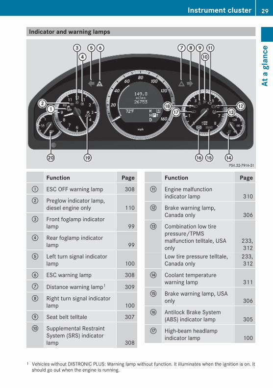
Indicator and warning lamps
Function Page
: ESC OFF warning lamp 308
; Preglow indicator lamp,diesel engine only 110
= Front foglamp indicatorlamp 99
? Rear foglamp indicatorlamp 99
A Left turn signal indicatorlamp 100
B ESC warning lamp 308
C Distance warning lamp1 309
D Right turn signal indicatorlamp 100
E Seat belt telltale 307
F Supplemental RestraintSystem (SRS) indicatorlamp 308
Function Page
G Engine malfunctionindicator lamp 310
H Brake warning lamp,Canada only 306
I Combination low tirepressure/TPMSmalfunction telltale, USAonly
233,312
Low tire pressure telltale,Canada only
233,312
J Coolant temperaturewarning lamp 311
K Brake warning lamp, USAonly 306
L Antilock Brake System(ABS) indicator lamp 305
M High-beam headlampindicator lamp 100
1 Vehicles without DISTRONIC PLUS: Warning lamp without function. It illuminates when the ignition is on. Itshould go out when the engine is running.
Instrument cluster 29
At a
gla
nce
212_AKB; 2; 41, en-USd2ureepe, Version: 2.11.8.1
2009-07-17T09:14:21+02:00 - Seite 29
Z

Function Page
N Low-beam headlampindicator lamp 97
O ESC SPORT warning lamp 67
P Fuel tank reserve warninglamp 310
Multifunction steering wheel
Function Page
: Multifunction display 128
; Press button W or Xto set the volume. 134Press button ~:to end a call 136to reject an incoming call 136Press button 6:to answer a call 136to dial2 136to redial2 137Press button 8 to mute.
= Press button ? toactivate the Voice ControlSystem3.
2 Function only available in telephone menu.3 Function only available in vehicles with Voice Control System.
30 Multifunction steering wheelAt
a g
lanc
e
212_AKB; 2; 41, en-USd2ureepe, Version: 2.11.8.1
2009-07-17T09:14:21+02:00 - Seite 30

Function Page
? Press button % briefly:to go to the next highermenu level 128to confirm display message 128to cancel the Voice ControlSystem3
Press and hold button% to select the standarddisplay. 128
A Press button = or ;: 128to call up line for menusto scroll to the left or rightto select menusPress button 9 or :briefly: 128to select submenusto scroll up or down throughliststo select previous or nexttrack, scene, or storedstation within Audio menu 134to switch to the phone bookand select a name ornumber within Tel menu 135Press and hold button9 or :: 128to select previous or nexttrack or scene with quicksearch or to select previousor next station in waveband(if no station list isavailable) within Audiomenu 134to start the quick search inthe phone book within Telmenu 135
Function PagePress button a:to confirm selection ormessage 128to switch to the phonebook2 135to dial a selected phonenumber2 136
3 Function only available in vehicles with Voice Control System.2 Function only available in telephone menu.
Multifunction steering wheel 31
At a
gla
nce
212_AKB; 2; 41, en-USd2ureepe, Version: 2.11.8.1
2009-07-17T09:14:21+02:00 - Seite 31
Z

Center console
Function Page
: Hazard warning flasherswitch 101
; Alarm system indicatorlamp 72
= Front passenger front airbag off indicator lamp, USAonly
43,314
Front passenger front airbag off indicator lamp,Canada only
46,314
? Electronic Stability Controlsystem (ESC) switch 65
A COMAND system, seeseparate operatinginstructions
B Seat heating switch 92
C Seat ventilation switch 92
D Parktronic systemdeactivation switch 168
Function Page
E Rear seat head restraintsswitch, folding down 89
F Rear window sunshadeswitch 205
G Dual-zone automaticclimate control 1813-zone automatic climatecontrol, Canada only 183Rear window defroster 191
H Storage compartment 201Ashtray 206Cup holder 203
I Damping system switch 163
J Vehicle level control switch 163
K Storage compartment 201
L Program mode selectorswitch 120
M COMAND controller, seeseparate operatinginstructions
32 Center consoleAt
a g
lanc
e
212_AKB; 2; 41, en-USd2ureepe, Version: 2.11.8.1
2009-07-17T09:14:21+02:00 - Seite 32
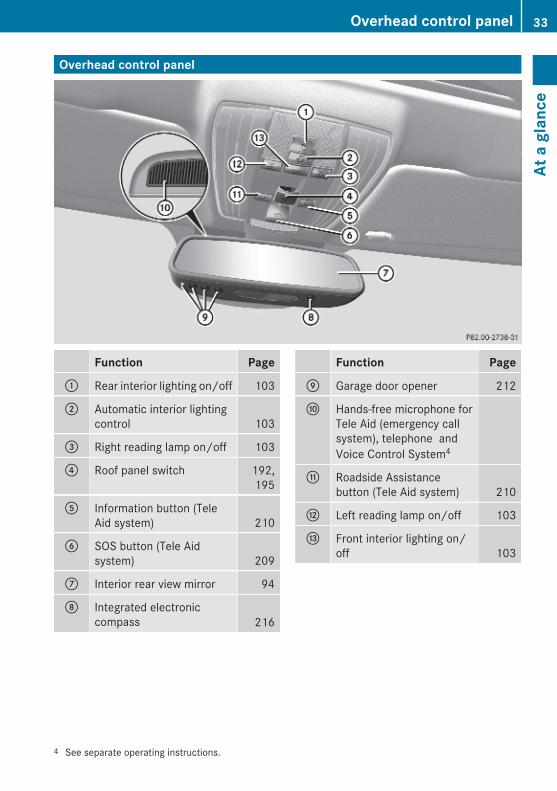
Overhead control panel
Function Page
: Rear interior lighting on/off 103
; Automatic interior lightingcontrol 103
= Right reading lamp on/off 103
? Roof panel switch 192,195
A Information button (TeleAid system) 210
B SOS button (Tele Aidsystem) 209
C Interior rear view mirror 94
D Integrated electroniccompass 216
Function Page
E Garage door opener 212
F Hands-free microphone forTele Aid (emergency callsystem), telephone andVoice Control System4
G Roadside Assistancebutton (Tele Aid system) 210
H Left reading lamp on/off 103
I Front interior lighting on/off 103
4 See separate operating instructions.
Overhead control panel 33
At a
gla
nce
212_AKB; 2; 41, en-USd2ureepe, Version: 2.11.8.1
2009-07-17T09:14:21+02:00 - Seite 33
Z

Door control panel
Function Page
: Memory function (forstoring seat, exterior mirrorand steering wheelsettings) 96
; Seat adjustment switches 88
= Central locking/unlockingswitch 81
? Inside door handle 80
A Exterior rear view mirroradjustment 95
B Switches for opening/closing front and rear doorwindows 105
C Rear door window overrideswitch 60
D Trunk opening switch, trunkopening/closing system 81
34 Door control panelAt
a g
lanc
e
212_AKB; 2; 41, en-USd2ureepe, Version: 2.11.8.1
2009-07-17T09:14:21+02:00 - Seite 34

Vehicle equipment .............................. 36Occupant safety .................................. 36Panic alarm .......................................... 61Driving safety systems ....................... 61Anti-theft systems .............................. 71
35
Safe
ty a
nd s
ecur
ity
212_AKB; 2; 41, en-USd2ureepe, Version: 2.11.8.1
2009-07-17T09:14:21+02:00 - Seite 35
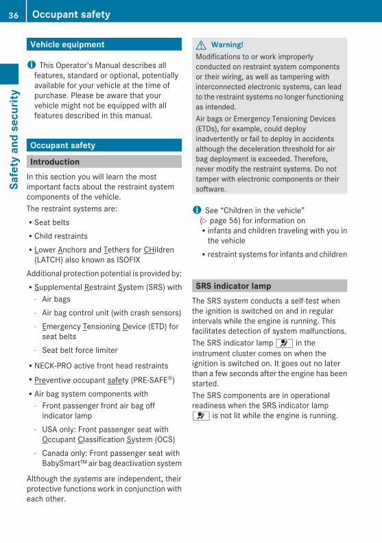
Vehicle equipment
i This Operator’s Manual describes allfeatures, standard or optional, potentiallyavailable for your vehicle at the time ofpurchase. Please be aware that yourvehicle might not be equipped with allfeatures described in this manual.
Occupant safety
IntroductionIn this section you will learn the mostimportant facts about the restraint systemcomponents of the vehicle.The restraint systems are:RSeat beltsRChild restraintsRLower Anchors and Tethers for CHildren
(LATCH) also known as ISOFIXAdditional protection potential is provided by:RSupplemental Restraint System (SRS) with
- Air bags- Air bag control unit (with crash sensors)- Emergency Tensioning Device (ETD) for
seat belts- Seat belt force limiter
RNECK-PRO active front head restraintsRPreventive occupant safety (PRE-SAFE®)RAir bag system components with
- Front passenger front air bag offindicator lamp
- USA only: Front passenger seat withOccupant Classification System (OCS)
- Canada only: Front passenger seat withBabySmart™ air bag deactivation system
Although the systems are independent, theirprotective functions work in conjunction witheach other.
G Warning!Modifications to or work improperlyconducted on restraint system componentsor their wiring, as well as tampering withinterconnected electronic systems, can leadto the restraint systems no longer functioningas intended.Air bags or Emergency Tensioning Devices(ETDs), for example, could deployinadvertently or fail to deploy in accidentsalthough the deceleration threshold for airbag deployment is exceeded. Therefore,never modify the restraint systems. Do nottamper with electronic components or theirsoftware.
i See “Children in the vehicle”(Y page 56) for information onRinfants and children traveling with you in
the vehicleRrestraint systems for infants and children
SRS indicator lampThe SRS system conducts a self-test whenthe ignition is switched on and in regularintervals while the engine is running. Thisfacilitates detection of system malfunctions.The SRS indicator lamp 6 in theinstrument cluster comes on when theignition is switched on. It goes out no laterthan a few seconds after the engine has beenstarted.The SRS components are in operationalreadiness when the SRS indicator lamp6 is not lit while the engine is running.
36 Occupant safetySa
fety
and
sec
urity
212_AKB; 2; 41, en-USd2ureepe, Version: 2.11.8.1
2009-07-17T09:14:21+02:00 - Seite 36
G Warning!The SRS self-check has detected amalfunction when the SRS indicator lamp6
Rdoes not come on at allRfails to go out after approximately
4 seconds after the engine was startedRcomes on after the engine was started or
while driving
For your safety, we strongly recommend thatyou contact an authorized Mercedes-BenzCenter immediately to have the systemchecked. Otherwise the SRS may not beactivated when needed in an accident, whichcould result in serious or fatal injury. The SRSmight also deploy unexpectedly andunnecessarily which could also result in injuryas well.In addition, improper work on the SRS createsa risk of rendering the SRS inoperative orcausing unintended air bag deployment. Workon the SRS must therefore only be performedby qualified technicians. Contact anauthorized Mercedes-Benz Center.If it is necessary to modify an air bag systemto accommodate a person with disabilities,contact an authorized Mercedes-Benz Center.USA only: Call our Customer AssistanceCenter at 1-800-FOR-MERCedes(1-800-367-6372) for details.
Air bags
G Warning!Air bags are designed to reduce the potentialof injury and fatality in certainRfrontal impacts (front air bags and driver’s
side knee bag)Rside impacts (side impact air bags, window
curtain air bags and pelvis air bags)Rrollovers (window curtain air bags)
However, no system available today cancompletely eliminate injuries and fatalities.Deployment of the air bags temporarilyreleases a small amount of dust from the airbags. This dust, however, is neither harmfulto your health, nor does it indicate a fire in thevehicle. The dust might cause sometemporary breathing difficulty for people withasthma or other breathing trouble. To avoidthis, you may wish to get out of the vehicle assoon as it is safe to do so. If you have anybreathing difficulty but cannot get out of thevehicle after the air bag inflates, then get freshair by opening a window or door.
G Warning!To reduce the risk of injury when the front airbags inflate, it is very important for the driverand front passenger to always be in a properlyseated position and to wear their respectiveseat belt.For maximum protection in the event of acollision always be in normal seated positionwith your back against the seat backrest.Fasten your seat belt and make sure it isproperly positioned on your body.Since the air bag inflates with considerablespeed and force, a proper seating positionand correct positioning of the hands on thesteering wheel will help to keep you at a safedistance from the air bag. Occupants who arenot wearing their seat belt, are not seatedproperly or are too close to the air bag can beseriously injured or killed by an air bag as itinflates with great force instantaneously:RSit with the seat belt properly fastened in a
position that is as upright as possible withyour back against the seat backrest.RMove the driver’s seat as far back as
possible, still permitting proper operationof vehicle controls. The distance from thecenter of the driver’s chest to the center ofthe air bag cover on the steering wheelmust be at least 10 inches (25 cm) or more.You should be able to accomplish this by
Occupant safety 37
Safe
ty a
nd s
ecur
ity
212_AKB; 2; 41, en-USd2ureepe, Version: 2.11.8.1
2009-07-17T09:14:21+02:00 - Seite 37
Z

adjusting the seat and steering wheel. Ifyou have any difficulties, please contact anauthorized Mercedes-Benz Center.RDo not lean your head or chest close to the
steering wheel or dashboard.RKeep hands on the outside of the steering
wheel rim. Placing hands and arms insidethe rim can increase the risk and potentialseverity of hand/arm injury when the driverfront air bag inflates.RAdjust the front passenger seat as far as
possible rearward from the dashboardwhen the seat is occupied.ROccupants, especially children, should
never place their bodies or lean their headsin the area of the door where the sideimpact air bag inflates. This could result inserious injuries or death should the sideimpact air bag be deployed. Always sit asupright as possible, wear the seat beltproperly and use an appropriately sizedinfant restraint, toddler restraint, orbooster seat recommended for the size andweight of the child.RCanada only: Children 12 years old and
under must never ride in the front seat,except in a Mercedes-Benz authorizedBabySmart™ compatible child seat, whichoperates with the BabySmart™ air bagdeactivation system installed in the vehicleto deactivate the front passenger front airbag when it is installed properly. Otherwisethey will be struck by the air bag when itinflates in a crash. If this happens, seriousor fatal injury will result.
Failure to follow these instructions can resultin severe injuries to you or other occupants.If you sell your vehicle, it is important that youmake the buyer aware of this safetyinformation. Be sure to give the buyer thisOperator’s Manual.
G Warning!Accident research shows that the safest placefor children in an automobile is in a rear seat.There is a possibility for a side impact air bag-related injury if occupants, especiallychildren, are not properly seated or restrainedwhen next to a side impact air bag whichneeds to deploy rapidly in a side impact inorder to do its job.To help avoid the possibility of injury, pleasefollow these guidelines:
(1) Always sit as upright as possible,wear the seat belt properly, and forchildren 12 years old and under,use an appropriately sized infantrestraint, toddler restraint, orbooster seat recommended for thesize and weight of the child.
(2) Always wear seat belts properly.
Air bags are designed to deploy only in certainRfrontal impacts (front air bags and driver’s
side knee bag)Rside impacts (side impact air bags, pelvis
air bags and window curtain air bags) if thesystem determines the need for air bagdeploymentRrollovers (window curtain air bags)Only in the event of such a situation will theyprovide their supplemental protection.The driver and passengers should alwayswear their seat belts. Otherwise it is notpossible for the air bags to provide theirsupplemental protection.In case of other types of impacts and impactsbelow air bag deployment thresholds, airbags will not deploy. The driver andpassengers will then be protected to theextent possible by a properly fastened seatbelt. A properly fastened seat belt is alsoneeded to provide the best possibleprotection in a rollover.Air bags are not a substitute for seat belts.Always wear your seat belt, regardless of
38 Occupant safetySa
fety
and
sec
urity
212_AKB; 2; 41, en-USd2ureepe, Version: 2.11.8.1
2009-07-17T09:14:21+02:00 - Seite 38

whether or not your vehicle is equipped withair bags.It is important to your safety and that of yourpassengers to have deployed air bagsreplaced and to have any malfunctioning airbags repaired. This will help to make sure theair bags will continue to provide supplementalcrash protection for occupants.
Safety guidelines for the seat belt, Emergency Tensioning Device (ETD) and air bag
G Warning!RDamaged seat belts or seat belts that have
been subjected to stress in an accidentmust be replaced. Their anchoring pointsmust also be checked. Only use seat beltsinstalled or supplied by an authorizedMercedes-Benz Center.RAir bags and pyrotechnic Emergency
Tensioning Devices (ETDs) containperchlorate material, which may requirespecial handling and regard for theenvironment. Check with your localgovernment’s disposal guidelines.California residents, seewww.dtsc.ca.gov/HazardousWaste/Perchlorate/index.cfm.RAir bags and ETDs are designed to function
on a one-time-only basis. An air bag or ETDthat has deployed must be replaced. PRE-SAFE® has electrically operated reversiblepre-tensioners in addition to thepyrotechnic ETDs.RDo not pass seat belts over sharp edges.
They could tear.RDo not make any modification that could
change the effectiveness of the seat belts.RDo not bleach or dye seat belts as this may
severely weaken them. In a crash they maynot be able to provide adequate protection.RNo modifications of any kind may be made
to any components or wiring of the SRS.
RDo no change or remove any component orpart of the SRS.RDo not install additional trim material, seat
covers, badges, etc. over the steeringwheel hub, front passenger front air bagcover, outboard sides of the seatbackrests, door trim panels, or door frametrims.RDo not install additional electrical/
electronic equipment on or near SRScomponents and wiring.RKeep area between air bags and occupants
free of objects (e.g. packages, purses,umbrellas, etc.).RDo not hang items such as coat hangers
from the coat hooks or handles over thedoor. These items may be thrown around inthe vehicle and cause head and otherinjuries when the window curtain air bag isdeployed.RAir bag system components will be hot after
an air bag has inflated. Do not touch them.RNever place your feet on the instrument
panel, dashboard, or on the seat. Alwayskeep both feet on the floor in front of theseat.RImproper repair work on the SRS creates a
risk of rendering the SRS inoperative orcausing unintended air bag deployment.Work on the SRS must therefore only beperformed by qualified technicians.Contact an authorized Mercedes-BenzCenter.RFor your protection and the protection of
others, when scrapping the air bag unit orETD, our safety instructions must befollowed. These instructions are availablefrom any authorized Mercedes-BenzCenter.RGiven the considerable deployment speed,
required inflation volume, and the materialof the air bags, there is the possibility of
Occupant safety 39
Safe
ty a
nd s
ecur
ity
212_AKB; 2; 41, en-USd2ureepe, Version: 2.11.8.1
2009-07-17T09:14:21+02:00 - Seite 39
Z
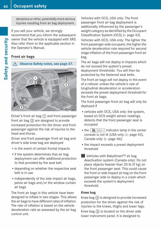
abrasions or other, potentially more seriousinjuries resulting from air bag deployment.
If you sell your vehicle, we stronglyrecommend that you inform the subsequentowner that the vehicle is equipped with SRS.Also refer them to the applicable section inthe Operator’s Manual.
Front air bags
G Observe Safety notes, see page 37.
Driver’s front air bag : and front passengerfront air bag ; are designed to provideincreased protection for the driver and frontpassenger against the risk of injuries to thehead and thorax.Driver and front passenger front air bag anddriver’s side knee bag are deployedRin the event of certain frontal impactsRif the system determines that air bag
deployment can offer additional protectionto that provided by the seat beltRdepending on whether the respective seat
belt is in useRindependently of the side impact air bags,
pelvis air bags and/or the window curtainair bags
The front air bags in this vehicle have beendesigned to inflate in two stages. This allowsthe air bags to have different rates of inflation.The rate of inflation is based on the vehicledeceleration rate as assessed by the air bagcontrol unit.
Vehicles with OCS, USA only: The frontpassenger front air bag deployment isadditionally influenced by the passenger’sweight category as identified by the OccupantClassification System (OCS) (Y page 43).Vehicles with OCS, USA only: The lighter thefront passenger-side occupant, the higher thevehicle deceleration rate required for secondstage inflation of the front passenger front airbag.The air bags will not deploy in impacts whichdo not exceed the system’s presetdeployment thresholds. You will then beprotected by the fastened seat belts.The front air bags will not deploy in the eventof a rollover unless the vehicle’s rate oflongitudinal deceleration or accelerationexceeds the preset deployment threshold forthe front air bags.The front passenger front air bag will only bedeployed ifRvehicles with OCS, USA only: the system,
based on OCS weight sensor readings,detects that the front passenger seat isoccupiedRthe 45 indicator lamp in the center
console is not lit (USA only: (Y page 43),Canada only: (Y page 46))Rthe impact exceeds a preset deployment
threshold
! Vehicles with BabySmart™ air bagdeactivation system (Canada only): Do notplace objects heavier than 20 lb (9 kg) onthe front passenger seat. This could causethe front or side impact air bag on the frontpassenger side to deploy in a crash whichexceeds the system’s deploymentthreshold.
Knee bag Knee bag = is designed to provide increasedprotection for the driver against the risk ofinjuries to the knees, thighs and lower legs.Knee bag = is located on the driver sidelower instrument panel. It is designed to
40 Occupant safetySa
fety
and
sec
urity
212_AKB; 2; 41, en-USd2ureepe, Version: 2.11.8.1
2009-07-17T09:14:21+02:00 - Seite 40
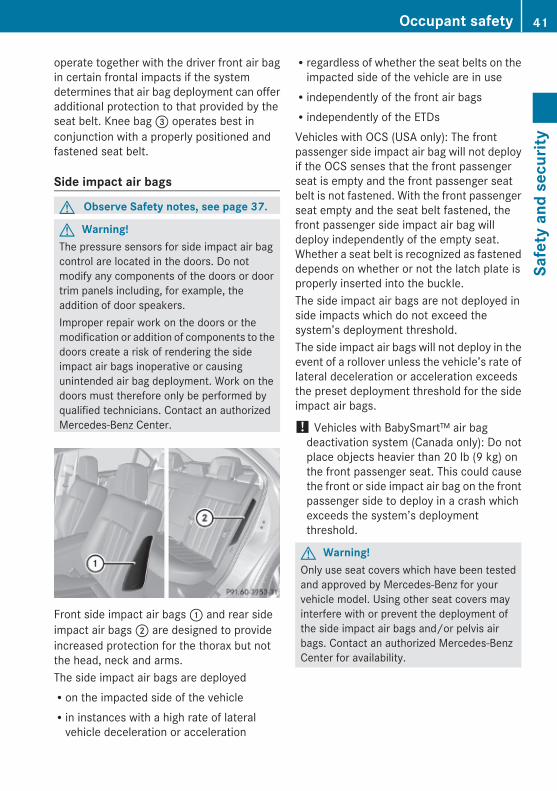
operate together with the driver front air bagin certain frontal impacts if the systemdetermines that air bag deployment can offeradditional protection to that provided by theseat belt. Knee bag = operates best inconjunction with a properly positioned andfastened seat belt.
Side impact air bags
G Observe Safety notes, see page 37.
G Warning!The pressure sensors for side impact air bagcontrol are located in the doors. Do notmodify any components of the doors or doortrim panels including, for example, theaddition of door speakers.Improper repair work on the doors or themodification or addition of components to thedoors create a risk of rendering the sideimpact air bags inoperative or causingunintended air bag deployment. Work on thedoors must therefore only be performed byqualified technicians. Contact an authorizedMercedes-Benz Center.
Front side impact air bags : and rear sideimpact air bags ; are designed to provideincreased protection for the thorax but notthe head, neck and arms.The side impact air bags are deployedRon the impacted side of the vehicleRin instances with a high rate of lateral
vehicle deceleration or acceleration
Rregardless of whether the seat belts on theimpacted side of the vehicle are in useRindependently of the front air bagsRindependently of the ETDsVehicles with OCS (USA only): The frontpassenger side impact air bag will not deployif the OCS senses that the front passengerseat is empty and the front passenger seatbelt is not fastened. With the front passengerseat empty and the seat belt fastened, thefront passenger side impact air bag willdeploy independently of the empty seat.Whether a seat belt is recognized as fasteneddepends on whether or not the latch plate isproperly inserted into the buckle.The side impact air bags are not deployed inside impacts which do not exceed thesystem’s deployment threshold.The side impact air bags will not deploy in theevent of a rollover unless the vehicle’s rate oflateral deceleration or acceleration exceedsthe preset deployment threshold for the sideimpact air bags.
! Vehicles with BabySmart™ air bagdeactivation system (Canada only): Do notplace objects heavier than 20 lb (9 kg) onthe front passenger seat. This could causethe front or side impact air bag on the frontpassenger side to deploy in a crash whichexceeds the system’s deploymentthreshold.
G Warning!Only use seat covers which have been testedand approved by Mercedes-Benz for yourvehicle model. Using other seat covers mayinterfere with or prevent the deployment ofthe side impact air bags and/or pelvis airbags. Contact an authorized Mercedes-BenzCenter for availability.
Occupant safety 41
Safe
ty a
nd s
ecur
ity
212_AKB; 2; 41, en-USd2ureepe, Version: 2.11.8.1
2009-07-17T09:14:21+02:00 - Seite 41
Z

Pelvis air bags
G Observe Safety notes, see page 37.
Pelvis air bags : are designed to provideincreased protection for the pelvis.Pelvis air bags : are deployedRin instances with a high rate of lateral
vehicle deceleration or accelerationRon the impacted side of the vehicleRindependently of whether the seat belt is in
useRindependently of the front air bagsRindependently of the ETDsVehicles with OCS, USA only: Frontpassenger pelvis air bag : will not deploy ifthe OCS senses that the front passenger seatis empty and the front passenger seat belt isnot fastened. With the front passenger seatempty and the seat belt fastened, frontpassenger pelvis air bag : will deployindependently of the empty seat. Whether aseat belt is recognized as fastened dependson whether or not the latch plate is properlyinserted into the buckle.Pelvis air bags : are not deployed in sideimpacts which do not exceed the system’sdeployment threshold.Pelvis air bags : will not deploy in the eventof a rollover unless the vehicle’s rate of lateraldeceleration or acceleration exceeds thepreset deployment threshold for pelvis airbags :.
G Warning!Only use seat covers which have been testedand approved by Mercedes-Benz for yourvehicle model. Using other seat covers mayinterfere with or prevent the deployment ofthe side impact air bags and/or pelvis airbags. Contact an authorized Mercedes-BenzCenter for availability.
Window curtain air bags
G Observe Safety notes, see page 37.
Window curtain air bags : are designed toprovide increased protection for the head butnot the chest or arms.Window curtain air bags : are deployedRon the impacted side of the vehicleRin instances with a high rate of lateral
vehicle deceleration or accelerationRindependently of the front air bagsRregardless of whether the front passenger
seat is occupiedRregardless of whether the seat belt on the
impacted side of the vehicle is in useRin certain vehicle rollovers, if the system
determines that air bag deployment canoffer additional protection to that providedby the seat belt
Window curtain air bags : are not deployedin impacts which do not exceed the system’sdeployment threshold.Window curtain air bags : deploy in the areaindicated by the arrows.
42 Occupant safetySa
fety
and
sec
urity
212_AKB; 2; 41, en-USd2ureepe, Version: 2.11.8.1
2009-07-17T09:14:21+02:00 - Seite 42

Occupant Classification SystemThe Occupant Classification System (OCS) isstandard equipment in USA.The OCS activates or deactivates the frontpassenger front air bag automatically. Therespective status is based on the classifiedoccupant weight category determined byweight sensor readings from the frontpassenger seat.The system does not deactivateRthe front passenger side impact air bagRthe pelvis air bagRthe window curtain air bagRthe Emergency Tensioning Devices (ETDs)To be classified correctly, the front passengermust sitRwith the seat belt properly fastenedRin a position that is as upright as possible
with the back against the seat backrestRwith the feet on the floorIf the occupant’s weight is transferred toanother object in the vehicle (e.g. by leaningon armrests), the OCS may not be able toproperly approximate the occupant’s weightcategory.If your seat, including the trim cover andcushion, needs to be serviced in any way, takethe vehicle to an authorized Mercedes-BenzCenter.Only seat accessories approved byMercedes-Benz may be used.Both the driver and the front passengershould always use the 45 indicatorlamp as an indication of whether or not thefront passenger is properly positioned.
G Warning!If the 45 indicator lamp illuminateswhen an adult or someone larger than a smallindividual is in the front passenger seat, havethe front passenger reposition himself or
herself in the seat until the 45indicator lamp goes out.In the event of a collision, the air bag controlunit will not allow front passenger front air bagdeployment when the OCS has classified thefront passenger seat occupant as weightingas much as or less than a typical 12-month-old child in a standard child restraint or if thefront passenger seat is classified as beingempty.When the OCS senses that the frontpassenger seat occupant is classified asbeing up to or less than the weight of a typical12-month-old child in a standard childrestraint, the 45 indicator lamp willilluminate when the engine is started andremain illuminated, indicating that the frontpassenger front air bag is deactivated.When the OCS senses that the frontpassenger seat is classified as being empty,the 45 indicator lamp will illuminatewhen the engine is started and remainilluminated, indicating that the frontpassenger front air bag is deactivated.When the OCS senses that the frontpassenger seat occupant is classified asbeing heavier than the weight of a typical12-month-old child seated in a standard childrestraint or as being a small individual (suchas a young teenager or a small adult), the45 indicator lamp will illuminate forapproximately 6 seconds when the engine isstarted and then, depending on occupantweight sensor readings from the seat, remainilluminated or go out. With the 45indicator lamp illuminated, the frontpassenger front air bag is deactivated. Withthe 45 indicator lamp out, the frontpassenger front air bag is activated.When the OCS senses that the frontpassenger seat occupant is classified as anadult or someone larger than a smallindividual, the 45 indicator lamp willilluminate for approximately 6 seconds whenthe engine is started and then goes out,
Occupant safety 43
Safe
ty a
nd s
ecur
ity
212_AKB; 2; 41, en-USd2ureepe, Version: 2.11.8.1
2009-07-17T09:14:21+02:00 - Seite 43
Z

indicating that the front passenger front airbag is activated.If the 45 indicator lamp is illuminated,the front passenger front air bag isdeactivated and will not be deployed.If the 45 indicator lamp is notilluminated, the front passenger front air bagis activated and will be deployedRin the event of certain frontal impactsRif impact exceeds a preset deployment
thresholdRindependently of the side impact air bags
or pelvis air bag
If the front passenger front air bag isdeployed, the rate of inflation will beinfluenced byRthe rate of relevant vehicle deceleration as
assessed by the air bag control unitRthe front passenger’s weight category as
identified by the OCS
For more information on air bag displaymessages in the multifunction display, see(Y page 276).
G Warning!According to accident statistics, children aresafer when properly restrained in the rearseating positions than in the front seatingposition. Thus, we strongly recommend thatchildren be placed in the rear seats wheneverpossible. Regardless of seating position,children 12 years old and under must beseated and properly secured in an appropriateinfant restraint, toddler restraint, or boosterseat recommended for the size and weight ofthe child.The infant or child restraint must be properlysecured with the vehicle’s seat belt, the seatbelt and top tether strap, or lower anchors andtop tether strap, fully in accordance with thechild seat manufacturer’s instructions.Occupants, especially children, should alwayssit as upright as possible, wear the seat belt
properly and use an appropriately sized infantrestraint, toddler restraint, or booster seatrecommended for the size and weight of thechild.Children can be killed or seriously injured byan inflating air bag. Note the followingimportant information when circumstancesrequire you to place a child in the frontpassenger seat:RYour vehicle is equipped with air bag
technology designed to deactivate the frontpassenger front air bag in your vehiclewhen the system senses the weight of atypical 12-month-old child or less alongwith the weight of a standard appropriatechild restraint on the front passenger seat.RA child in a rear-facing child restraint on the
front passenger seat will be seriouslyinjured or even killed if the front passengerfront air bag inflates in a collision whichcould occur under some circumstances,even with the air bag technology installedin your vehicle. The only means tocompletely eliminate this risk is to neverplace a child in a rear-facing child restraintin the front seat. We therefore stronglyrecommend that you always place a childin a rear-facing child restraint in a backseat.RIf you must install a rear-facing child
restraint on the front passenger seatbecause circumstances require you to doso, make sure the 45 indicator lampis illuminated, indicating that the frontpassenger front air bag is deactivated.Should the 45 indicator lamp notilluminate or go out while the restraint isinstalled, please check installation.Periodically check the 45 indicatorlamp while driving to make sure the45 indicator lamp is illuminated. Ifthe 45 indicator lamp goes out orremains out, do not transport a child on thefront passenger seat until the system hasbeen repaired.
44 Occupant safetySa
fety
and
sec
urity
212_AKB; 2; 41, en-USd2ureepe, Version: 2.11.8.1
2009-07-17T09:14:21+02:00 - Seite 44

A child in a rear-facing child restraint on thefront passenger seat will be seriouslyinjured or even killed if the front passengerfront air bag inflates.RIf you have to place a child in a forward-
facing child restraint on the front passengerseat, move the seat as far back as possible,use the proper child restraintrecommended for the age, size and weightof the child, and secure child restraint withthe vehicle’s seat belt according to the childseat manufacturer’s instructions. Forchildren larger than the typical 12-month-old child, the front passenger front air bagmay or may not be activated.
Deployment of the driver front air bag doesnot mean that the front passenger front airbag also should have deployed.The OCS may have determinedRthat the seat was empty or occupied by the
weight up to or less than that of a typical12-month-old child seated in a standardchild restraint – both of which are instanceswhere the system suppresses deploymentof the front passenger front air bag eventhough the impact met the criteria and wasof sufficient severity to deploy the driverfront air bagRthat the seat was occupied by a small
individual (such as a young teenager or asmall adult) or a child who weighs morethan the weight of a typical 12-month-oldchild in a standard child restraint – both ofwhich are instances where the system maysuppress deployment of the frontpassenger front air bag even though theimpact met the criteria and was ofsufficient severity to deploy the driver frontair bag
45 indicator lamp : will beilluminated, except with the SmartKeyremoved from the starter switch or with thestarter switch in position 0.
G Warning!If the red SRS indicator lamp 6 in theinstrument cluster and the 45indicator lamp are lit at the same time, thereis a malfunction in the OCS. The frontpassenger front air bag will be deactivated inthis case. Have the system checked byqualified technicians as soon as possible.Contact an authorized Mercedes-BenzCenter.Only have the seat repaired or replaced at anauthorized Mercedes-Benz Center.In order to ensure proper operation of the airbag system and OCS:RSit with the seat belt properly fastened in a
position that is as upright as possible withyour back against the seat backrest.RWhile seated, an occupant should not
position him/herself in such a way as tocause the occupant’s weight to be liftedfrom the seat bottom as this may result inthe OCS being unable to correctlyapproximate the occupant’s weightcategory.RRead and observe all warnings in this
chapter.
Occupant safety 45
Safe
ty a
nd s
ecur
ity
212_AKB; 2; 41, en-USd2ureepe, Version: 2.11.8.1
2009-07-17T09:14:21+02:00 - Seite 45
Z
OCS Self-test After turning the SmartKey in the starterswitch to position 1 or 2 or pressing theKEYLESS-GO start/stop button once ortwice, the 45 indicator lampilluminates. If an adult occupant is properlysitting on the front passenger seat and thesystem classifies the occupant as an adult,the 45 indicator lamp will illuminateand go out after approximately 6 seconds.If the seat is not occupied and the systemclassifies the front passenger seat as beingempty, the 45 indicator lamp willilluminate and not go out.
G Warning!If the 45 indicator lamp does notilluminate, the system is not functioning. Youmust contact an authorized Mercedes-BenzCenter before seating any child on the frontpassenger seat.
For more information, see the “Practicalhints” section (Y page 314).
G Warning!Never place anything between seat cushionand child seat (e.g. pillow), since it reducesthe effectiveness of the OCS. The bottom andback of the child seat must make full contactwith the passenger seat cushion andbackrest.If necessary, adjust the tilt of the passengerseat backrest.An incorrectly mounted child seat could causeinjuries to the child in case of an accident,instead of increasing protection for the child.Follow the manufacturer’s instructions forinstallation of child seats.
BabySmart™ air bag deactivation system
The BabySmart™ air bag deactivation systemis standard equipment in Canada.
G Warning!According to accident statistics, children aresafer when properly restrained in the rearseating positions than in the front seatingposition. Thus, we strongly recommend thatchildren be placed in the rear seats wheneverpossible. Regardless of seating position,children 12 years old and under must beseated and properly secured in an appropriateinfant restraint, toddler restraint, or boosterseat recommended for the size and weight ofthe child.The infant or child restraint must be properlysecured with the vehicle’s seat belt, the seatbelt and top tether strap, or lower anchors andtop tether strap, fully in accordance with thechild seat manufacturer’s instructions.Occupants, especially children, should alwayssit as upright as possible, wear the seat beltproperly and use an appropriately sized infantrestraint, toddler restraint, or booster seatrecommended for the size and weight of thechild.Children can be killed or seriously injured byan inflating air bag. Note the followingimportant information when circumstancesrequire you to place a child in the frontpassenger seat:RChildren 12 years old and under must never
ride in the front seat, except in a Mercedes-Benz authorized BabySmart™ compatiblechild seat, which operates with theBabySmart™ system installed in the vehicleto deactivate the front passenger front airbag when it is installed properly. Otherwisethey will be struck by the air bag when itinflates in a crash. If this happens, seriousor fatal injury will result.RA child in a rear-facing child restraint on the
front passenger seat will be seriouslyinjured or even killed if the front passengerfront air bag inflates in a collision whichcould occur under some circumstances,even with the air bag technology installedin your vehicle. The only means to
46 Occupant safetySa
fety
and
sec
urity
212_AKB; 2; 41, en-USd2ureepe, Version: 2.11.8.1
2009-07-17T09:14:21+02:00 - Seite 46
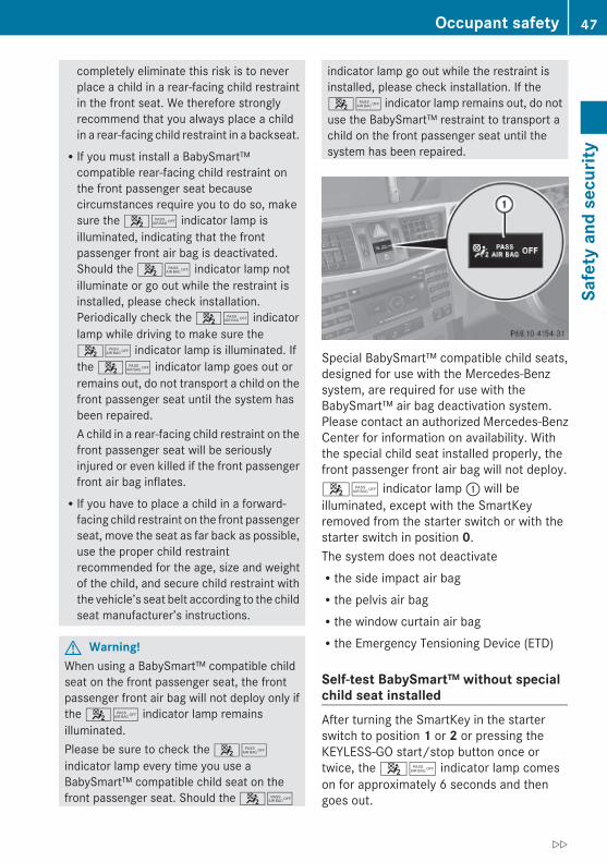
completely eliminate this risk is to neverplace a child in a rear-facing child restraintin the front seat. We therefore stronglyrecommend that you always place a childin a rear-facing child restraint in a backseat.RIf you must install a BabySmart™
compatible rear-facing child restraint onthe front passenger seat becausecircumstances require you to do so, makesure the 45 indicator lamp isilluminated, indicating that the frontpassenger front air bag is deactivated.Should the 45 indicator lamp notilluminate or go out while the restraint isinstalled, please check installation.Periodically check the 45 indicatorlamp while driving to make sure the45 indicator lamp is illuminated. Ifthe 45 indicator lamp goes out orremains out, do not transport a child on thefront passenger seat until the system hasbeen repaired.A child in a rear-facing child restraint on thefront passenger seat will be seriouslyinjured or even killed if the front passengerfront air bag inflates.RIf you have to place a child in a forward-
facing child restraint on the front passengerseat, move the seat as far back as possible,use the proper child restraintrecommended for the age, size and weightof the child, and secure child restraint withthe vehicle’s seat belt according to the childseat manufacturer’s instructions.
G Warning!When using a BabySmart™ compatible childseat on the front passenger seat, the frontpassenger front air bag will not deploy only ifthe 45 indicator lamp remainsilluminated.Please be sure to check the 45indicator lamp every time you use aBabySmart™ compatible child seat on thefront passenger seat. Should the 45
indicator lamp go out while the restraint isinstalled, please check installation. If the45 indicator lamp remains out, do notuse the BabySmart™ restraint to transport achild on the front passenger seat until thesystem has been repaired.
Special BabySmart™ compatible child seats,designed for use with the Mercedes-Benzsystem, are required for use with theBabySmart™ air bag deactivation system.Please contact an authorized Mercedes-BenzCenter for information on availability. Withthe special child seat installed properly, thefront passenger front air bag will not deploy.45 indicator lamp : will beilluminated, except with the SmartKeyremoved from the starter switch or with thestarter switch in position 0.The system does not deactivateRthe side impact air bagRthe pelvis air bagRthe window curtain air bagRthe Emergency Tensioning Device (ETD)
Self-test BabySmart™ without special child seat installed After turning the SmartKey in the starterswitch to position 1 or 2 or pressing theKEYLESS-GO start/stop button once ortwice, the 45 indicator lamp comeson for approximately 6 seconds and thengoes out.
Occupant safety 47
Safe
ty a
nd s
ecur
ity
212_AKB; 2; 41, en-USd2ureepe, Version: 2.11.8.1
2009-07-17T09:14:21+02:00 - Seite 47
Z

If the 45 indicator lamp should notcome on or is continuously lit, the system isnot functioning. You must see an authorizedMercedes-Benz Center before seating anychild on the front passenger seat. Moreinformation can be found in the “Practicalhints” section (Y page 313).
G Warning!Do not place powered-on laptops, mobilephones, electronic tags such as those used inski passes and like electronic devices on thefront passenger seat. Signals from suchdevices may interfere with the BabySmart™air bag deactivation system. Such signalinterference may cause the 45indicator lamp not to come on during self-test.The SRS indicator lamp 6 and/or the45 indicator lamp could becontinuously lit, indicating that the system isnot functioning. The front passenger front airbag could deploy inadvertently or fail todeploy in an accident.
G Warning!The BabySmart™ air bag deactivation systemwill ONLY work with a special child seatdesigned to operate with it. It will not workwith child seats which are not BabySmart™compatible.Never place anything between seat cushionand child seat (e.g. pillow), since it reducesthe effectiveness off the BabySmart™ air bagdeactivation system. The bottom of the childseat must make full contact with the frontpassenger seat cushion. An incorrectlymounted child seat could cause injuries to thechild in case of an accident, instead ofprotecting the child.Follow the manufacturer’s instructions forinstallation of special child seats.
Seat belts
Safety notesThe use of seat belts and infant and childrestraint systems is required by law in all 50states, the District of Columbia, the U.S.territories and all Canadian provinces.Even where this is not the case, all vehicleoccupants should have their seat beltsfastened whenever the vehicle is in motion.
i See “Children in the vehicle”(Y page 56) for information onRinfants and children traveling with you in
the vehicleRrestraint systems for infants and children
G Warning!Always fasten your seat belt before driving off.Always make sure all of your passengers areproperly restrained. You and your passengersshould always wear seat belts.Failure to wear and properly fasten andposition your seat belt greatly increases yourrisk of injuries and their likely severity in anaccident.If you are ever in an accident, your injuries canbe considerably more severe without yourseat belt properly buckled. Without your seatbelt buckled, you are much more likely to hitthe interior of the vehicle or be ejected fromit. You can be seriously injured or killed.In the same crash, the possibility of injury ordeath is lessened if you are properly wearingyour seat belt. The air bags can only protectas intended if the occupants are properlywearing their seat belts.
G Warning!Never ride in a moving vehicle with the seatbackrest in an excessively reclined position asthis can be dangerous. You could slide underthe seat belt in a collision. If you slide underit, the seat belt would apply force at theabdomen or neck. That could cause seriousor even fatal injuries. The seat backrest and
48 Occupant safetySa
fety
and
sec
urity
212_AKB; 2; 41, en-USd2ureepe, Version: 2.11.8.1
2009-07-17T09:14:21+02:00 - Seite 48

seat belt provide the best restraint when thewearer is in a position that is as upright aspossible and the seat belt is properlypositioned on the body.
G Warning!Never let more people ride in the vehicle thanthere are seat belts available. Make sureeveryone riding in the vehicle is correctlyrestrained with a separate seat belt. Neveruse a seat belt for more than one person at atime.
G Warning!Damaged seat belts or seat belts that havebeen subjected to stress in an accident mustbe replaced. Also, the seat belt anchoringpoints must be checked.Only use seat belts which have been approvedby Mercedes-Benz.Do not make any modifications to the seatbelts. This can lead to unintended activationof the ETDs or to their failure to activate whennecessary.Do not bleach or dye seat belts as this mayseverely weaken them. In a crash they maynot be able to provide adequate protection.Have all work carried out only by qualifiedtechnicians. Contact an authorizedMercedes-Benz Center.
Proper use of seat belts
G Warning!USE SEAT BELTS PROPERLYRSeat belts can only protect when used
properly. Never wear seat belts in any otherway than as described in this section, asthat could result in serious injuries in caseof an accident.REach occupant should wear their seat belt
at all times, because seat belts help reducethe likelihood of and potential severity ofinjuries in accidents, including rollovers.The integrated restraint system includes
SRS (driver front air bag, driver side kneebag, front passenger front air bag, sideimpact air bags, pelvis air bags, windowcurtain air bags for door windows),Emergency Tensioning Devices (ETDs),seat belt force limiters, and front seat kneebolsters.The system is designed to enhance theprotection offered to properly beltedoccupants in certain frontal (front air bags,driver’s side knee bag, and ETDs) and side(side impact air bags, pelvis air bags,window curtain air bags, and ETDs) impactswhich exceed preset deploymentthresholds and in certain rollovers (windowcurtain air bags and ETDs).RNever wear the shoulder belt under your
arm, against your neck or off your shoulder.In a frontal crash, your body would movetoo far forward. That would increase thechance of head and neck injuries. The seatbelt would also apply too much force to theribs or abdomen, which could severelyinjure internal organs such as your liver orspleen.Adjust the seat belt so that the shouldersection is located as close as possible tothe middle of the shoulder. It should nottouch the neck. Never pass the shoulderportion of the seat belt under your arm. Forthis purpose, you can adjust the height ofthe seat belt outlet.RPosition the lap belt as low as possible on
your hips and not across the abdomen. Ifthe lap belt is positioned across yourabdomen, it could cause serious injuries ina crash.RNever wear seat belts over rigid or
breakable objects in or on your clothing,such as eyeglasses, pens, keys etc., asthese might cause injuries.RMake sure the seat belt is always fitted
snugly. Take special care of this whenwearing loose clothing.
Occupant safety 49
Safe
ty a
nd s
ecur
ity
212_AKB; 2; 41, en-USd2ureepe, Version: 2.11.8.1
2009-07-17T09:14:21+02:00 - Seite 49
Z

RNever use a seat belt for more than oneperson at a time. Do not fasten a seat beltaround a person and another person orother objects at the same time.RSeat belts should not be worn twisted. In a
crash, you would not have the full width ofthe seat belt to distribute impact forces.The twisted seat belt against your bodycould cause injuries.RPregnant women should also always use a
lap/shoulder belt. The lap belt portionshould be positioned as low as possible onthe hips to avoid any possible pressure onthe abdomen.RPlace the seat backrest in a position that is
as upright as possible.RCheck your seat belt during travel to make
sure it is properly positioned.RNever place your feet on the instrument
panel, dashboard, or on the seat. Alwayskeep both feet on the floor in front of theseat.RWhen using a seat belt to secure infant
restraints, toddler restraints, or children inbooster seats, always follow the child seatmanufacturer’s instructions.
G Warning!Do not pass seat belts over sharp edges. Theycould tear.Do not allow the seat belt to get caught in thedoor or in the seat adjustment mechanism.This could damage the seat belt.Never attempt to make modifications to seatbelts. This could impair the effectiveness ofthe seat belts.
Fastening the seat belts
G Warning!According to accident statistics, children aresafer when properly restrained in the rearseating positions than in the front seatingposition. Thus, we strongly recommend that
children be placed in the rear seats wheneverpossible. Regardless of seating position,children 12 years old and under must beseated and properly secured in anappropriately sized infant restraint, toddlerrestraint, or booster seat recommended forthe size and weight of the child. For additionalinformation, see “Children in the vehicle”.A child’s risk of serious or fatal injuries issignificantly increased if the child restraintsare not properly secured in the vehicle and/or the child is not properly secured in the childrestraint.
G Warning!Vehicles with BabySmart™ air bagdeactivation system, Canada only: Children12 years old and under must never ride in thefront seat, except in a Mercedes-Benzauthorized BabySmart™ compatible childseat, which operates with the BabySmart™system installed in the vehicle to deactivatethe front passenger front air bag when it isinstalled properly. Otherwise they will bestruck by the air bag when it inflates in acrash. If this happens, serious or fatal injurywill result.
50 Occupant safetySa
fety
and
sec
urity
212_AKB; 2; 41, en-USd2ureepe, Version: 2.11.8.1
2009-07-17T09:14:21+02:00 - Seite 50

X With a smooth motion, pull the seat belt outof seat belt outlet :.
X Place the shoulder portion of the seat beltacross the top of your shoulder and the lapportion across your hips.
X Push latch plate ; into buckle = until itclicks.Seat belt adjustment function: The seatbelts on both front seats adjust to theupper body automatically as necessary(Y page 51).
X If necessary, adjust the seat belt to thecorrect height (Y page 51).
X If necessary, tighten the lap portion to asnug fit by pulling shoulder portion up.
All lap/shoulder belts except the driver’s seatbelt have special seat belt retractors tosecure child restraints properly. For moreinformation on special seat belt retractors,see “Infant and child restraint systems”(Y page 56).To release the seat belt with seat belt releasebutton ?, see (Y page 51).
Seat belt adjustment functionThe seat belt adjustment function adjusts theseat belts on both front seats to the upperbody of the respective vehicle occupant. Theseat belt will be pulled slightly tighter for thatpurpose whenRyou engage the latch plate into the buckle
and then turn the SmartKey in the starterswitch to position 2Rthe SmartKey in the starter switch is in
position 2 and you then engage the latchplate in the buckle
The seat belt adjustment function takes placewith a certain amount of retracting forcewhen the system senses slack between thevehicle occupant and the seat belt. Do notretain the seat belt during this procedure. Youcan activate or deactivate the seat beltadjustment function via the control system(Y page 145).
Releasing the seat beltsX Press seat belt release button ?
(Y page 50).Allow the retractor to completely rewindthe seat belt by guiding latch plate ;(Y page 50).
! Make sure the seat belt retractscompletely. Otherwise the seat belt and/orlatch plate could get caught or pinched inthe door or in the seat mechanism. This candamage the seat belt and impair itseffectiveness, and/or cause damage to thedoor and/or door trim panel. Such damageis not covered by the Mercedes-BenzLimited Warranty.Damaged seat belts must be replaced.Contact an authorized Mercedes-BenzCenter.
Rear center seat beltThe seat belt of the rear center seat may beblocked when the left rear seat backrest isfolded forward and back (Y page 199). Theseat belt can then not be pulled out.X Unblocking the seat belt of the rear
center seat: Pull the center seat beltapproximately 1 in (25 mm) out of the seatbelt outlet in the seat backrest and releaseit.The seat belt is retracted and unblocked.
Seat belt outlet height adjustmentYou can adjust the height of the seat beltoutlet for the driver’s and front passengerseat.
Occupant safety 51
Safe
ty a
nd s
ecur
ity
212_AKB; 2; 41, en-USd2ureepe, Version: 2.11.8.1
2009-07-17T09:14:21+02:00 - Seite 51
Z

X Raising: Slide the seat belt outlet heightadjuster upward.The seat belt outlet height adjusterengages in different positions.
X Lowering: Press and hold releasebutton :.
X Slide the seat belt outlet height adjusterdownward.
X Release release button : and make surethe seat belt outlet height adjuster engagesinto place.
Enhanced seat belt reminder systemWhen the engine is started, the seat belttelltale 7 will always illuminate for6 seconds to remind you and your passengersto fasten your seat belts.If the driver’s seat belt is not fastened whenthe engine is started, an additional warningchime will sound. The warning chime goes outafter approximately 6 seconds or once thedriver’s seat belt is fastened.If after these 6 seconds the driver’s or thefront passenger’s seat belt (with the frontpassenger seat occupied) is not fastened withfront doors closed,Rthe seat belt telltale 7 remains
illuminated for as long as either the driver’sor front passenger’s seat belt is notfastened.Rand if the vehicle speed once exceeds
15 mph (25 km/h), the seat belt telltale7 starts flashing and a warning chime
sounds with increasing intensity for amaximum of 60 seconds or until thedriver’s and front passenger’s seat belt arefastened.If you and/or your passenger release theseat belt during driving, the seat belttelltale 7 starts flashing and thewarning chime sounds as described before.If the driver’s or the front passenger’s seatbelt remains unfastened after 60 seconds,the warning chime stops sounding, the seatbelt telltale 7 stops flashing butcontinues to be illuminated.After a vehicle standstill, the warning chimeis reactivated and the seat belt telltale7 is flashing again if the vehicle speedonce exceeds 15 mph (25 km/h).
The seat belt telltale 7 will only go out ifboth the driver’s and the front passenger’sseat belt (with the front passenger seatoccupied) are fastened, or the vehicle isstanding still and a front door is opened.For more information, see “Practical hints”(Y page 307).
Emergency Tensioning Device (ETD), seat belt force limiterThe seat belts for the front seats and rearouter seats are equipped with ETDs and seatbelt force limiters.The ETDs are designed to activate in thefollowing cases:Rin frontal or rear-end impacts exceeding
the system’s preset deployment thresholdRin side impacts exceeding the system’s
preset deployment threshold on the farside of the impactRin certain vehicle rolloversRif the restraint systems are operational and
functioning correctly, see “SRS indicatorlamp” (Y page 36)
The ETDs for the front seats will only activateif the front seat belts are fastened (latch plateproperly inserted into buckle).
52 Occupant safetySa
fety
and
sec
urity
212_AKB; 2; 41, en-USd2ureepe, Version: 2.11.8.1
2009-07-17T09:14:21+02:00 - Seite 52

The ETDs for the rear outer seats will activatewith or without the respective seat beltsfastened.In an impact, the ETDs remove slack from theseat belts in such a way that the seat belts fitmore snugly against the body. Seat belt forcelimiters, when activated, are employed tohelp reduce the peak force exerted by theseat belts on occupants during a crash.
i The ETDs do not correct an incorrect seatposition or incorrectly worn seat belts.The ETDs do not pull occupants backtoward the seat backrest.
G Warning!Pyrotechnic ETDs that were activated must bereplaced.For your safety, when disposing of thepyrotechnic ETDs always follow our safetyinstructions. These are available at anyauthorized Mercedes-Benz Center.The PRE-SAFE® system has electricallyoperated reversible pre-tensioners that donot require replacement after activation.
Automatic comfort-fit feature seat beltAn automatic comfort-fit feature for the frontseats reduces the retracting force of the seatbelts when they are in normal use.
Preventive occupant safety (PRE-SAFE®)
G Warning!The PRE-SAFE® system is intended to reducethe effects of an accident on vehicleoccupants who are wearing their seat beltproperly. Despite your vehicle being equippedwith the PRE-SAFE® system, the possibility ofpersonal injuries occurring as a result of anaccident cannot be eliminated. Therefore,always drive carefully and adjust your drivingto the prevailing road, weather, and trafficconditions.
The PRE-SAFE® system takes preventivemeasures to better protect the occupantsfrom the possibility of personal injuries in thefollowing hazardous situations:Remergency braking situations, e.g. if the
Brake Assist System (BAS) (Y page 63) isactivatedor whenvehicles with DISTRONIC PLUS:the BAS PLUS (Y page 63) or the PRE-SAFE® Brake (Y page 69) is stronglyengagingRwhen the radar sensors recognize the
immediate risk of collision in certainsituations (vehicles with DISTRONIC PLUS)Rcritical dynamic driving situations, e.g.
when the vehicle has been caused toundersteer or oversteer because it hasexceeded its physical limitations or in caseof evasive steering maneuvers at speedsabove approximately 85 mph (140 km/h)
The PRE-SAFE® system takes the followingmeasures when it is activated:RThe front seat belts are pre-tensioned
automatically.RIf the front passenger seat is in an
unfavorable position, the seat will beadjusted to a position that seeks to betterprotect the occupant.RThe system increases the air pressure in
the air pockets (on the sides of the seatcushion and backrest) of the drive-dynamicmulticontour front seats.RIf the vehicle is in a critical dynamic driving
situation, the door windows and the tilt/sliding sunroof or panorama roof with tilt/sliding panel also closes, except for aminimal gap that remains open.
If the closing procedure of any of theseelements is blocked, it will stop and openslightly.Once the hazardous situation no longer existsand an accident has been avoided, the PRE-SAFE® system loosens the seat belt pre-
Occupant safety 53
Safe
ty a
nd s
ecur
ity
212_AKB; 2; 41, en-USd2ureepe, Version: 2.11.8.1
2009-07-17T09:14:21+02:00 - Seite 53
Z

tension and decreases the air pressure in theair pockets of the drive-dynamic multicontourfront seats. All of the PRE-SAFE® systemsettings can be re-adjusted following thecritical driving event.If the seat belts do not release:X Adjust the seat backrest or seat slightly to
the rear until the seat belt tension isreduced.The locking mechanism releases.
! When moving the seats, make sure thereare no items in the footwell or behind theseats. Otherwise, you could damage theseats and/or the items.
For information on the seat belt adjustmentfunction as an integrated comfort feature ofthe PRE-SAFE® system, see (Y page 51).
NECK-PRO active front head restraints
The NECK-PRO active front head restraintsare intended to offer the driver and frontpassenger increased protection fromwhiplash-type injuries. In the event of a rear-end collision, the NECK-PRO active front headrestraints are designed to move forward andup in the direction of travel. They thus providethe head with increased support earlier on inthe collision sequence. The NECK-PRO activefront head restraints will move forward andup whether the seats are occupied or not.
G Warning!Do not attach any objects (e.g. hangers) to thehead restraint posts. Otherwise, the NECK-PRO active front head restraints may not beable to function properly or offer the intendeddegree of protection they were designed forin the event of a rear-end collision.
G Warning!Only use seat or head restraint covers whichhave been tested and approved by Mercedes-Benz for your vehicle model.
Using other seat or head restraint covers mayinterfere with or prevent the activation of theNECK-PRO active front head restraints and/or the deployment of the front side impact airbags or pelvis air bags.Contact an authorized Mercedes-Benz Centerfor availability.
When the NECK-PRO active front headrestraints have been triggered in an accident,the NECK-PRO active front head restraintsmust be reset. Otherwise, the NECK-PROactive front head restraints cannot offer anyadditional protection in the event of anotherrear-end collision.For information on resetting the activatedNECK-PRO active front head restraints, see“Resetting activated head restraints”(Y page 316).You cannot remove the NECK-PRO activefront head restraints.
G Warning!For your protection, drive only with properlypositioned head restraints.Adjust the head restraint so that it is as closeto the head as possible and the center of thehead restraint supports the back of the headat eye level. This will reduce the potential forinjury to the head and neck in the event of anaccident or similar situation.
For information on head restraint adjustment,see “Head restraint height” (Y page 89), orsee “Head restraint fore and aft adjustment”(Y page 89).
Correct driver seat adjustment
G Warning!In order to avoid possible loss of vehiclecontrol the following must be done before thevehicle is put into motion:Rseat adjustmentRhead restraint adjustment
54 Occupant safetySa
fety
and
sec
urity
212_AKB; 2; 41, en-USd2ureepe, Version: 2.11.8.1
2009-07-17T09:14:21+02:00 - Seite 54
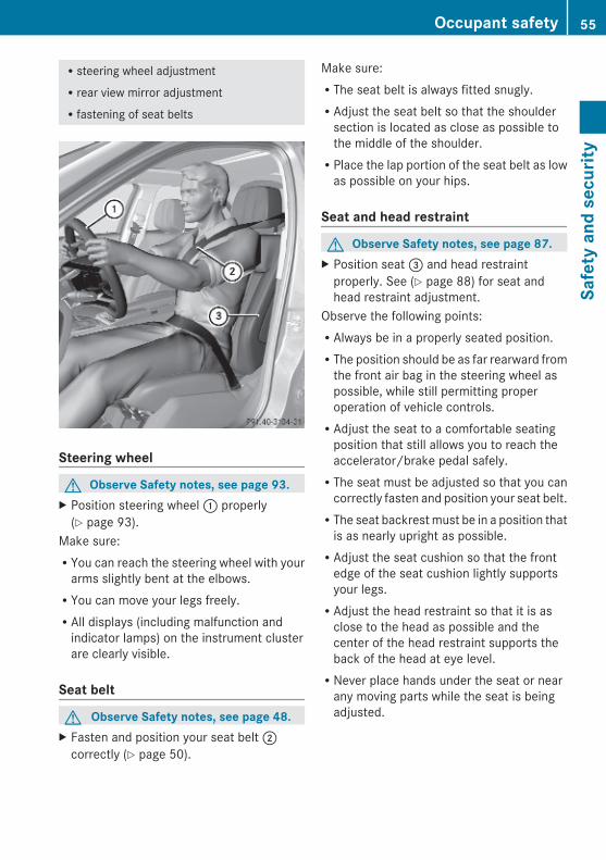
Rsteering wheel adjustmentRrear view mirror adjustmentRfastening of seat belts
Steering wheel
G Observe Safety notes, see page 93.X Position steering wheel : properly
(Y page 93).Make sure:RYou can reach the steering wheel with your
arms slightly bent at the elbows.RYou can move your legs freely.RAll displays (including malfunction and
indicator lamps) on the instrument clusterare clearly visible.
Seat belt
G Observe Safety notes, see page 48.X Fasten and position your seat belt ;
correctly (Y page 50).
Make sure:RThe seat belt is always fitted snugly.RAdjust the seat belt so that the shoulder
section is located as close as possible tothe middle of the shoulder.RPlace the lap portion of the seat belt as low
as possible on your hips.
Seat and head restraint
G Observe Safety notes, see page 87.X Position seat = and head restraint
properly. See (Y page 88) for seat andhead restraint adjustment.
Observe the following points:RAlways be in a properly seated position.RThe position should be as far rearward from
the front air bag in the steering wheel aspossible, while still permitting properoperation of vehicle controls.RAdjust the seat to a comfortable seating
position that still allows you to reach theaccelerator/brake pedal safely.RThe seat must be adjusted so that you can
correctly fasten and position your seat belt.RThe seat backrest must be in a position that
is as nearly upright as possible.RAdjust the seat cushion so that the front
edge of the seat cushion lightly supportsyour legs.RAdjust the head restraint so that it is as
close to the head as possible and thecenter of the head restraint supports theback of the head at eye level.RNever place hands under the seat or near
any moving parts while the seat is beingadjusted.
Occupant safety 55
Safe
ty a
nd s
ecur
ity
212_AKB; 2; 41, en-USd2ureepe, Version: 2.11.8.1
2009-07-17T09:14:21+02:00 - Seite 55
Z
Children in the vehicle
Safety notesIf an infant or child is traveling with you in thevehicle:X Secure the child using an infant or child
restraint appropriate to the age and size ofthe child.
X Make sure the infant or child is properlysecured at all times while the vehicle is inmotion.
G Warning!When leaving the vehicle, always remove theSmartKey from the starter switch. Alwaystake the SmartKey with you and lock thevehicle. Do not leave children unattended inthe vehicle, even if they are secured in a childrestraint system, or with access to anunlocked vehicle. A child’s unsupervisedaccess to a vehicle could result in an accidentand/or serious personal injury. The childrencouldRinjure themselves on parts of the vehicleRbe seriously or fatally injured through
excessive exposure to extreme heat or coldRinjure themselves or cause an accident with
vehicle equipment that can be operatedeven if the SmartKey is removed from thestarter switch or removed from the vehicle,such as seat adjustment, steering wheeladjustment, or the memory function
If children open a door, they could injure otherpersons or get out of the vehicle and injurethemselves or be injured by following traffic.Do not expose the child restraint system todirect sunlight. The child restraint system’smetal parts, for example, could become veryhot, and the child could be burned by theseparts.
G Warning!Do not carry heavy or hard objects in thepassenger compartment or trunk unless theyare firmly secured in place.
Unsecured or improperly positioned cargoincreases a child’s risk of injury in the eventofRstrong braking maneuversRsudden changes of directionRan accident
Infant and child restraint systems
G Observe Safety notes, see page 56.We recommend all infants and children beproperly restrained at all times while thevehicle is in motion.Canada only:Only use a BabySmart™ compatible childrestraint for the front passenger seat in thisvehicle.All lap/shoulder belts except the driver’s seatbelt have special seat belt retractors forsecure fastening of child restraints.To fasten a child restraint, follow the childrestraint manufacturer’s instructions formounting.To activate the special seat belt retractor:X Pull the shoulder belt out completely and
let it retract.During seat belt retraction, a ratchetingsound can be heard to indicate that thespecial seat belt retractor is activated.The seat belt is now locked.
X Push down on child restraint to take up anyslack.
To deactivate the special seat belt retractor:X Release the seat belt buckle and let the
seat belt retract completely.The seat belt can then again be used in theusual manner.
To deactivate the special seat belt retractorfor the front passenger seat, the frontpassenger seat must be in the most backwardposition.
56 Occupant safetySa
fety
and
sec
urity
212_AKB; 2; 41, en-USd2ureepe, Version: 2.11.8.1
2009-07-17T09:14:21+02:00 - Seite 56
G Warning!Never release the seat belt buckle while thevehicle is in motion, since the special seat beltretractor will be deactivated.
i Information on child seats with mountingfittings for tether anchorages(Y page 58).For information on LATCH-type (ISOFIX)child seat anchors (Y page 59).
The use of infant or child restraints is requiredby law in all 50 states, the District ofColumbia, the U.S. territories and allCanadian provinces.Infants and small children should be seatedin an appropriate infant or child restraintsystem. They must be properly secured inaccordance with the manufacturer’sinstructions for the child restraint. All infantor child restraint systems must comply withU.S. Federal Motor Vehicle Safety Standards213 and 225 and Canadian Motor VehicleSafety Standards 213 and 210.2.A statement by the child restraintmanufacturer of compliance with thesestandards can be found on the instructionlabel on the restraint and in the instructionmanual provided with the restraint.When using any infant restraint, toddlerrestraint, or booster seat, make sure tocarefully read and follow all manufacturer’sinstructions for installation and use.Please read and observe warning labelsaffixed to the inside of the vehicle and toinfant or child restraints.
G Warning!According to accident statistics, children aresafer when properly restrained in the rearseating positions than in the front seatingposition. Thus, we strongly recommend thatchildren be placed in the rear seats wheneverpossible. Regardless of seating position,children 12 years old and under must beseated and properly secured in an appropriate
infant restraint, toddler restraint, or boosterseat recommended for the size and weight ofthe child.The infant or child restraint must be properlysecured with the vehicle’s seat belt, the seatbelt and top tether strap, or lower anchors andtop tether strap, fully in accordance with thechild seat manufacturer’s instructions.Occupants, especially children, should alwayssit as upright as possible, wear the seat beltproperly and use an appropriately sized infantrestraint, toddler restraint, or booster seatrecommended for the size and weight of thechild.Children can be killed or seriously injured byan inflating air bag. Note the followingimportant information when circumstancesrequire you to place a child in the frontpassenger seat:RUSA only: Your vehicle is equipped with air
bag technology designed to deactivate thefront passenger front air bag in your vehiclewhen the system senses the weight of atypical 12-month-old child or less alongwith the weight of a standard appropriatechild restraint on the front passenger seat.RUSA only: For children larger than the
typical 12-month-old child, the frontpassenger front air bag may or may not beactivated. Always make sure the45 indicator lamp is illuminated,indicating that the front passenger front airbag is deactivated.RCanada only: Children 12 years old and
under must never ride in the front seat,except in a Mercedes-Benz authorizedBabySmart™ compatible child seat, whichoperates with the BabySmart™ systeminstalled in the vehicle to deactivate thefront passenger front air bag when it isinstalled properly. Otherwise they will bestruck by the air bag when it inflates in acrash. If this happens, serious or fatal injurywill result.
Occupant safety 57
Safe
ty a
nd s
ecur
ity
212_AKB; 2; 41, en-USd2ureepe, Version: 2.11.8.1
2009-07-17T09:14:21+02:00 - Seite 57
Z

RA child in a rear-facing child restraint on thefront passenger seat will be seriouslyinjured or even killed if the front passengerfront air bag inflates in a collision whichcould occur under some circumstances,even with the air bag technology installedin your vehicle. The only means tocompletely eliminate this risk is to neverplace a child in a rear-facing child restraintin the front seat. We therefore stronglyrecommend that you always place a childin a rear-facing child restraint in a backseat.RIf you must install a rear-facing child
restraint on the front passenger seatbecause circumstances require you to doso, make sure the 45 indicator lampis illuminated, indicating that the frontpassenger front air bag is deactivated.Should the 45 indicator lamp notilluminate or go out while the restraint isinstalled, please check installation.Periodically check the 45 indicatorlamp while driving to make sure the45 indicator lamp is illuminated. Ifthe 45 indicator lamp goes out orremains out, do not transport a child on thefront passenger seat until the system hasbeen repaired.A child in a rear-facing child restraint on thefront passenger seat will be seriouslyinjured or even killed if the front passengerfront air bag inflates.RIf you have to place a child in a forward-
facing child restraint on the front passengerseat, move the seat as far back as possible,use the proper child restraintrecommended for the age, size and weightof the child, and secure child restraint withthe vehicle’s seat belt according to the childseat manufacturer’s instructions.
G Warning!Infants and small children should never sharea seat belt with another occupant. During anaccident, they could be crushed between theoccupant and seat belt.
A child’s risk of serious or fatal injuries issignificantly increased if the child restraintsare not properly secured in the vehicle and/or the child is not properly secured in the childrestraint.Children too big for a toddler restraint mustride in seats using regular seat belts. Positionshoulder belt across chest and shoulder, notface or neck. A booster seat may benecessary to achieve proper seat beltpositioning for children over 41 lb (18 kg) untilthey reach a height where a lap/shoulder beltfits properly without a booster.When the child restraint is not in use, removeit from the vehicle or secure it with the seatbelt to prevent the child restraint frombecoming a projectile in the event of anaccident.
Installation of infant and child restraint systems
G Observe Safety notes, see page 56.
G Warning!Always lock the seat backrests in their uprightposition when the rear seats are occupied bypassengers. Lock the seat backrests in theirupright position before installing top tetherstraps or when the extended cargocompartment is not in use. Make sure thatseat backrests are secured properly bypushing and pulling on the seat backrests. Ifa seat backrest is not locked properly, theseat backrest could fold. The child seat wouldno longer be supported properly or positionedto provide its intended benefit. That couldcause serious or even fatal injuries.
This vehicle is equipped with tetheranchorages for a top tether strap at each ofthe rear seating positions.Top tether straps enable an additionalconnection to be made between childrestraint systems secured with LATCH-type(ISOFIX) anchors and rear seats. This canfurther reduce the risk of injury.
58 Occupant safetySa
fety
and
sec
urity
212_AKB; 2; 41, en-USd2ureepe, Version: 2.11.8.1
2009-07-17T09:14:21+02:00 - Seite 58
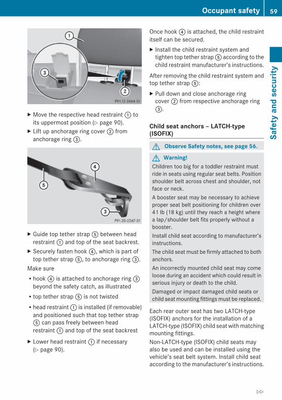
X Move the respective head restraint : toits uppermost position (Y page 90).
X Lift up anchorage ring cover ; fromanchorage ring =.
X Guide top tether strap A between headrestraint : and top of the seat backrest.
X Securely fasten hook ?, which is part oftop tether strap A, to anchorage ring =.
Make sureRhook ? is attached to anchorage ring =
beyond the safety catch, as illustratedRtop tether strap A is not twistedRhead restraint : is installed (if removable)
and positioned such that top tether strapA can pass freely between headrestraint : and top of the seat backrest
X Lower head restraint : if necessary(Y page 90).
Once hook ? is attached, the child restraintitself can be secured.X Install the child restraint system and
tighten top tether strap A according to thechild restraint manufacturer’s instructions.
After removing the child restraint system andtop tether strap A:X Pull down and close anchorage ring
cover ; from respective anchorage ring=.
Child seat anchors – LATCH-type (ISOFIX)
G Observe Safety notes, see page 56.
G Warning!Children too big for a toddler restraint mustride in seats using regular seat belts. Positionshoulder belt across chest and shoulder, notface or neck.A booster seat may be necessary to achieveproper seat belt positioning for children over41 lb (18 kg) until they reach a height wherea lap/shoulder belt fits properly without abooster.Install child seat according to manufacturer’sinstructions.The child seat must be firmly attached to bothanchors.An incorrectly mounted child seat may comeloose during an accident which could result inserious injury or death to the child.Damaged or impact damaged child seats orchild seat mounting fittings must be replaced.
Each rear outer seat has two LATCH-type(ISOFIX) anchors for the installation of aLATCH-type (ISOFIX) child seat with matchingmounting fittings.Non-LATCH-type (ISOFIX) child seats mayalso be used and can be installed using thevehicle’s seat belt system. Install child seataccording to the manufacturer’s instructions.
Occupant safety 59
Safe
ty a
nd s
ecur
ity
212_AKB; 2; 41, en-USd2ureepe, Version: 2.11.8.1
2009-07-17T09:14:21+02:00 - Seite 59
Z
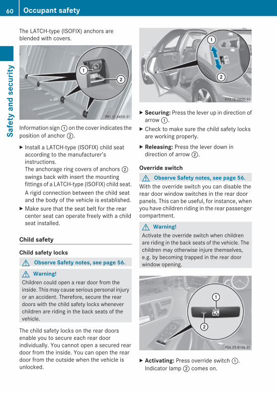
The LATCH-type (ISOFIX) anchors areblended with covers.
Information sign : on the cover indicates theposition of anchor ;.
X Install a LATCH-type (ISOFIX) child seataccording to the manufacturer’sinstructions.The anchorage ring covers of anchors ;swings back with insert the mountingfittings of a LATCH-type (ISOFIX) child seat.A rigid connection between the child seatand the body of the vehicle is established.
X Make sure that the seat belt for the rearcenter seat can operate freely with a childseat installed.
Child safety
Child safety locksG Observe Safety notes, see page 56.
G Warning!Children could open a rear door from theinside. This may cause serious personal injuryor an accident. Therefore, secure the reardoors with the child safety locks wheneverchildren are riding in the back seats of thevehicle.
The child safety locks on the rear doorsenable you to secure each rear doorindividually. You cannot open a secured reardoor from the inside. You can open the reardoor from the outside when the vehicle isunlocked.
X Securing: Press the lever up in direction ofarrow :.
X Check to make sure the child safety locksare working properly.
X Releasing: Press the lever down indirection of arrow ;.
Override switchG Observe Safety notes, see page 56.
With the override switch you can disable therear door window switches in the rear doorpanels. This can be useful, for instance, whenyou have children riding in the rear passengercompartment.
G Warning!Activate the override switch when childrenare riding in the back seats of the vehicle. Thechildren may otherwise injure themselves,e.g. by becoming trapped in the rear doorwindow opening.
X Activating: Press override switch :.Indicator lamp ; comes on.
60 Occupant safetySa
fety
and
sec
urity
212_AKB; 2; 41, en-USd2ureepe, Version: 2.11.8.1
2009-07-17T09:14:21+02:00 - Seite 60
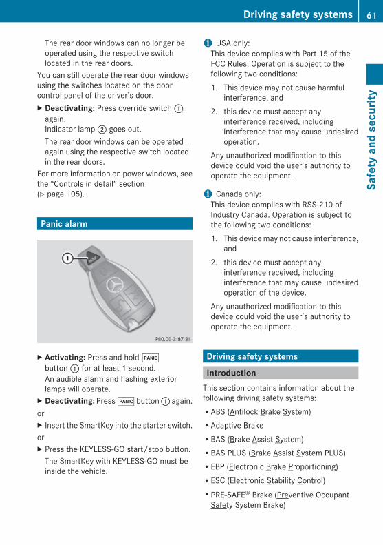
The rear door windows can no longer beoperated using the respective switchlocated in the rear doors.
You can still operate the rear door windowsusing the switches located on the doorcontrol panel of the driver’s door.X Deactivating: Press override switch :
again.Indicator lamp ; goes out.The rear door windows can be operatedagain using the respective switch locatedin the rear doors.
For more information on power windows, seethe “Controls in detail” section(Y page 105).
Panic alarm
X Activating: Press and hold !button : for at least 1 second.An audible alarm and flashing exteriorlamps will operate.
X Deactivating: Press ! button : again.orX Insert the SmartKey into the starter switch.orX Press the KEYLESS-GO start/stop button.
The SmartKey with KEYLESS-GO must beinside the vehicle.
i USA only:This device complies with Part 15 of theFCC Rules. Operation is subject to thefollowing two conditions:1. This device may not cause harmful
interference, and2. this device must accept any
interference received, includinginterference that may cause undesiredoperation.
Any unauthorized modification to thisdevice could void the user’s authority tooperate the equipment.
i Canada only:This device complies with RSS-210 ofIndustry Canada. Operation is subject tothe following two conditions:1. This device may not cause interference,
and2. this device must accept any
interference received, includinginterference that may cause undesiredoperation of the device.
Any unauthorized modification to thisdevice could void the user’s authority tooperate the equipment.
Driving safety systems
IntroductionThis section contains information about thefollowing driving safety systems:RABS (Antilock Brake System)RAdaptive BrakeRBAS (Brake Assist System)RBAS PLUS (Brake Assist System PLUS)REBP (Electronic Brake Proportioning)RESC (Electronic Stability Control)RPRE-SAFE® Brake (Preventive Occupant
Safety System Brake)
Driving safety systems 61
Safe
ty a
nd s
ecur
ity
212_AKB; 2; 41, en-USd2ureepe, Version: 2.11.8.1
2009-07-17T09:14:21+02:00 - Seite 61
Z
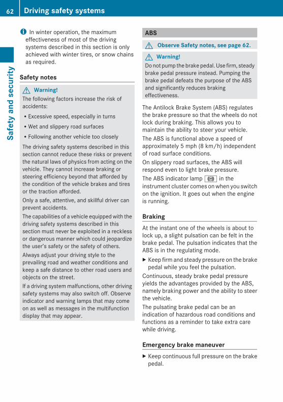
i In winter operation, the maximumeffectiveness of most of the drivingsystems described in this section is onlyachieved with winter tires, or snow chainsas required.
Safety notes
G Warning!The following factors increase the risk ofaccidents:RExcessive speed, especially in turnsRWet and slippery road surfacesRFollowing another vehicle too closely
The driving safety systems described in thissection cannot reduce these risks or preventthe natural laws of physics from acting on thevehicle. They cannot increase braking orsteering efficiency beyond that afforded bythe condition of the vehicle brakes and tiresor the traction afforded.Only a safe, attentive, and skillful driver canprevent accidents.The capabilities of a vehicle equipped with thedriving safety systems described in thissection must never be exploited in a recklessor dangerous manner which could jeopardizethe user’s safety or the safety of others.Always adjust your driving style to theprevailing road and weather conditions andkeep a safe distance to other road users andobjects on the street.If a driving system malfunctions, other drivingsafety systems may also switch off. Observeindicator and warning lamps that may comeon as well as messages in the multifunctiondisplay that may appear.
ABS
G Observe Safety notes, see page 62.
G Warning!Do not pump the brake pedal. Use firm, steadybrake pedal pressure instead. Pumping thebrake pedal defeats the purpose of the ABSand significantly reduces brakingeffectiveness.
The Antilock Brake System (ABS) regulatesthe brake pressure so that the wheels do notlock during braking. This allows you tomaintain the ability to steer your vehicle.The ABS is functional above a speed ofapproximately 5 mph (8 km/h) independentof road surface conditions.On slippery road surfaces, the ABS willrespond even to light brake pressure.The ABS indicator lamp ! in theinstrument cluster comes on when you switchon the ignition. It goes out when the engineis running.
BrakingAt the instant one of the wheels is about tolock up, a slight pulsation can be felt in thebrake pedal. The pulsation indicates that theABS is in the regulating mode.X Keep firm and steady pressure on the brake
pedal while you feel the pulsation.Continuous, steady brake pedal pressureyields the advantages provided by the ABS,namely braking power and the ability to steerthe vehicle.The pulsating brake pedal can be anindication of hazardous road conditions andfunctions as a reminder to take extra carewhile driving.
Emergency brake maneuverX Keep continuous full pressure on the brake
pedal.
62 Driving safety systemsSa
fety
and
sec
urity
212_AKB; 2; 41, en-USd2ureepe, Version: 2.11.8.1
2009-07-17T09:14:21+02:00 - Seite 62

G Warning!If the ABS malfunctions, other driving safetysystems such as the BAS or the ESC are alsoswitched off. Observe indicator and warninglamps that may come on as well as messagesin the multifunction display that may appear.If the ABS malfunctions, the wheels may lockduring hard braking, reducing steeringcapability and extending the braking distance.
BAS
G Observe Safety notes, see page 62.The Brake Assist System (BAS) operates inemergency situations. If you apply the brakesvery quickly, the BAS provides full brakeboost automatically, thereby potentiallyreducing the braking distance.X Apply continuous full braking pressure until
the emergency braking situation is over.The ABS will prevent the wheels fromlocking.
When you release the brake pedal, the brakesfunction again as normal. The BAS is thendeactivated.
G Warning!If the BAS malfunctions, the brake system stillfunctions, but without the additional brakeboost available that the BAS would normallyprovide in an emergency braking maneuver.Therefore, the braking distance may increase.
BAS PLUSThe Brake Assist System PLUS (BAS PLUS)operates in emergency braking situations anduses radar sensors to assess the trafficsituation. BAS PLUS assists you in braking atspeeds above approximately 20 mph(30 km/h).When traveling in Canada in a vehicle notregistered in Canada, you must switch off theradar sensor system (Y page 144). Canadianlaw does not permit the use of the radar
sensor system for vehicles from outside ofCanada.When you switch off the radar system, thefollowing functions are deactivated:RBAS PLUSRPRE-SAFE® Brake (Y page 69)RDISTRONIC PLUS (Y page 149)
G Warning!BAS PLUS is a convenience system designedto assist the driver during vehicle operation.The responsibility for the vehicle speed andthe distance to the vehicle ahead, includingmost importantly brake operation to assuresafe stopping distance, always remains withthe driver.Always pay attention to traffic conditionseven while BAS PLUS is switched on.Otherwise, you may not be able to recognizedangerous situations until it is too late andcould cause an accident. Personal or fatalinjury to you or others may be the result.
i This device has been approved by the FCCas a “Vehicular Radar System”. The radarsensor is intended for use in an automotiveradar system only. Removal, tampering, oraltering of the device will void anywarranties, and is not permitted by theFCC. Do not tamper with, alter, or use inany non-approved way.Any unauthorized modification to thisdevice could void the user’s authority tooperate the equipment.
BAS PLUS detects obstacles that are in yourdriving path for a sufficient period of time topermit the system to recognize theseobstacles. If you approach the detectedobstacle quickly, BAS PLUS calculates thelevel of brake power boost appropriate for thecircumstance to supply when the driverapplies the brakes.When you step quickly on the brake pedal inan emergency braking situation, BAS PLUSautomatically regulates the brake power
Driving safety systems 63
Safe
ty a
nd s
ecur
ity
212_AKB; 2; 41, en-USd2ureepe, Version: 2.11.8.1
2009-07-17T09:14:21+02:00 - Seite 63
Z
boost to a level that is suitable for the trafficsituation.If BAS PLUS requires a particularly high brakepower boost, PRE-SAFE® is activated at thesame time.X Keep constant pressure on the brake pedal
until the emergency braking situation isover.During this process, the ABS prevents thewheels from locking up.
The brakes will resume normal operationafterRthe brake pedal is releasedRno obstacles are detected in your pathRthe system no longer senses a risk of a
collisionBAS PLUS is then deactivated.BAS PLUS can react to stationary obstaclessuch as standing or parked vehicles at roadspeeds of up to approximately 40 mph(70 km/h).BAS PLUS can only assist you when the radarsensors are switched on and functional. Youcan check whether the sensors are active byswitching on DISTRONIC PLUS(Y page 149) or using the Radar sensorsfunction in the instrument cluster controlsystem.
G Warning!BAS PLUS will only respond with brakeassistance if it has clearly detected an object.Detection can be impeded byRdirty or covered sensorsRsnowfall or heavy rainRdisturbance from other radar sourcesRstrong radar reflection such as in parking
garages
BAS PLUS uses radar signals that are notreflected well by narrow objects andabsorptive materials. For this reason BASPLUS will not react to persons, animals, andapproaching traffic or cross-traffic.
BAS PLUS may not detect narrow vehiclesdriving in front of you, such as motorcyclesand vehicles driving offset from your vehiclecenter.
After a hard collision or damage to the frontof the vehicle from an accident, have theadjustment and operation of the radarsensors checked by an authorized Mercedes-Benz Center.If BAS PLUS is not available due to a radarsensor malfunction, the braking system willcontinue to function normally with full brakeboost and full standard BAS function.
Adaptive BrakeAdaptive Brake provides a high level ofbraking safety as well as increased brakingcomfort. Adaptive Brake takes driver andvehicle characteristics into consideration,thus achieving an optimal braking effect.In addiditon, Adaptive Brake provides theHOLD function (Y page 161) and the hill-startassist system (Y page 160).For more information on the brake system,see (Y page 254).
EBP
G Observe Safety notes, see page 62.The Electronic Brake Proportioning (EBP)enhances braking effectiveness by allowingthe rear brakes to supply a greater proportionof the braking effort in straight-line brakingwithout a loss of vehicle stability.
G Warning!If the EBP malfunctions, the brake system willstill function with full brake boost. However,the rear wheels could lock up duringemergency braking situations, for example.You could lose control of the vehicle andcause an accident.Adapt your driving style to the changeddriving characteristics.
64 Driving safety systemsSa
fety
and
sec
urity
212_AKB; 2; 41, en-USd2ureepe, Version: 2.11.8.1
2009-07-17T09:14:21+02:00 - Seite 64

ESC
G Observe Safety notes, see page 62.The Electronic Stability Control (ESC) isoperational as soon as the engine is running.It monitors the vehicle’s traction (force ofadhesive friction between the tires and theroad surface) and handling.The ESC recognizes that the vehicle deviatesfrom the direction of travel as intended by thedriver. By applying brakes to individualwheels and by limiting the engine output, theESC works to stabilize the vehicle. The ESC isespecially useful while driving off and on wetor slippery road surfaces. The ESC alsostabilizes the vehicle during braking andsteering maneuvers.The ESC warning lamp ä in the instrumentcluster comes on when you switch on theignition. It goes out when the engine isrunning.
G Warning!Never switch off the ESC when you see theESC warning lamp ä flashing in theinstrument cluster. In this case proceed asfollows:RWhen driving off, apply as little throttle as
possible.RWhile driving, ease up on the accelerator
pedal.RAdapt your speed and driving style to the
prevailing road conditions.
Failure to observe these guidelines couldcause the vehicle to skid. The ESC cannotprevent accidents resulting from excessivespeed.
! Vehicles with 4MATIC: Because the ESCoperates automatically, the engine andignition must be shut off (SmartKey instarter switch position 0 or 1 or KEYLESS-GO start/stop button in position 0 or 1)when the parking brake is being tested ona brake test dynamometer.
Active braking action through the ESC mayotherwise seriously damage the brakesystem which is not covered by theMercedes-Benz Limited Warranty.
! Vehicles without 4MATIC: Because theESC operates automatically, the engineand ignition must be shut off (SmartKey instarter switch position 0 or 1 or KEYLESS-GO start/stop button in position 0 or 1)when the parking brake is being tested ona brake test dynamometer or when thevehicle is being towed with one axle raised.Active braking action through the ESC mayotherwise seriously damage the brakesystem which is not covered by theMercedes-Benz Limited Warranty.
! The ESC will only function properly if youuse wheels of the recommended tire sizeas specified in the “Technical data” sectionof this Operator’s Manual.
i The DISTRONIC PLUS and cruise controlswitch off automatically when the ESCengages.
Electronic Traction System (ETS/4-ETS)
G Observe Safety notes, see page 62.The ETS (Electronic Traction System) and4-ETS (four-wheel Electronic TractionSystem, vehicles with 4MATIC only) arecomponents of the ESC. The ETS/4-ETSimproves the vehicle’s ability to utilizeavailable traction, especially under slipperyroad conditions by applying the brakes to aspinning wheel. Vehicles with 4MATIC alsotransfer more power to the wheel(s) withtraction.When you switch off the ESC, theETS/4-ETS is still enabled.
Driving safety systems 65
Safe
ty a
nd s
ecur
ity
212_AKB; 2; 41, en-USd2ureepe, Version: 2.11.8.1
2009-07-17T09:14:21+02:00 - Seite 65
Z

Switching the ESC off or on (except E 63 AMG)
G Warning!The ESC should not be switched off duringnormal driving other than in thecircumstances described below. Disablingthe system will reduce vehicle stability indriving maneuvers.Do not switch off the ESC when a spare wheelis mounted.
To improve the vehicle’s traction, switch offthe ESC. This allows the drive wheels to spinand thus cut into surfaces for better grip, forexampleRwhen driving with snow chainsRin deep snowRin sand or gravel
G Warning!Switch on the ESC immediately if theaforementioned circumstances do not applyanymore. Otherwise the ESC will not stabilizethe vehicle when it is starting to skid or awheel is spinning.
When you switch off the ESC,Rthe ESC does not stabilize the vehicleRthe engine output is not limited, which
allows the drive wheels to spin and thus cutinto surfaces for better gripRthe ETS/4-ETS will still apply the brakes to
a spinning wheelRthe ESC continues to operate when you are
brakingRthe cruise control or the DISTRONIC PLUS
cannot be activatedRthe cruise control or the DISTRONIC PLUS
switch off if activated
i When the ESC is switched off and one ormore drive wheels are spinning, the ESCwarning lamp ä in the instrument
cluster flashes. However, the ESC will thennot stabilize the vehicle.
X Switching off: With the engine running,press ESC switch : until the ESC OFFwarning lamp å in the instrumentcluster comes on.The ESC is switched off.
G Warning!When the ESC OFF warning lamp å is on,the ESC is switched off.When the ESC warning lamp ä and theESC OFF warning lamp å are oncontinuously, the ESC is not operational dueto a malfunction.When the ESC is switched off or notoperational, vehicle stability in standarddriving maneuvers is reduced.Adapt your speed and driving to the prevailingroad conditions and to the non-operatingstatus of the ESC.
! Avoid spinning of a drive wheel for anextended period with the ESC switched off.This may cause serious damage to thedrivetrain which is not covered by theMercedes-Benz Limited Warranty.
X Switching on: Press ESC switch : untilthe ESC OFF warning lamp å in theinstrument cluster goes out.You are now again in normal driving modewith the ESC switched on.
66 Driving safety systemsSa
fety
and
sec
urity
212_AKB; 2; 41, en-USd2ureepe, Version: 2.11.8.1
2009-07-17T09:14:21+02:00 - Seite 66

E 63 AMG
Switching ESC SPORT on or offG Warning!ESC SPORT should not be switched on duringnormal driving.Switching ESC SPORT on will result in thefollowing:Rno restriction to engine torqueRsystem-supported traction control is
limited
ESC SPORT is designed for driving on closedtracks when the vehicle’s natural oversteerand understeer characteristics are desiredand requires a highly skilled and experienceddriver able to handle these critical drivingsituations.You could lose control of your vehicle andcause an accident.Please be aware of these limits when youswitch on ESC SPORT.Do not switch on ESC SPORT when a sparewheel is mounted.
To improve the vehicle’s traction, switch onESC SPORT. This allows the drive wheels tospin and thus cut into surfaces for better grip,for exampleRwhen driving with snow chainsRin deep snowRin sand or gravel
G Warning!Switch off ESC SPORT and switch on the ESCimmediately if the aforementionedcircumstances do not apply anymore.Otherwise ESC will only stabilize the vehicleto a limited extent when it is starting to skidor a wheel is spinning.
When you switch on ESC SPORTRthe ESC stabilizes the vehicle only to a
limited extentRthe engine output is limited, but only to the
extent that allows the drive wheels to spinand thus cut into surfaces for better gripRthe ETS will still apply the brakes to a
spinning wheelRthe ESC continues to operate when you are
braking hardRthe cruise control or the DISTRONIC PLUS
cannot be activatedRthe cruise control or the DISTRONIC PLUS
switch off if activated
i When ESC SPORT is switched on and oneor more drive wheels are spinning, the ESCwarning lamp ä in the instrumentcluster flashes. However, the ESC will thenstabilize the vehicle only to a limited extent.
X Switching on: With the engine running,press ESC SPORT switch : briefly.The ESC SPORT warning lamp ì in theinstrument cluster comes on. The messageESC-SPORT appears in the multifunctiondisplay.
X Switching off: With the engine running,press ESC SPORT switch : briefly.The ESC SPORT warning lamp ì in theinstrument cluster goes out. The messageESC-ON appears in the multifunctiondisplay.
Driving safety systems 67
Safe
ty a
nd s
ecur
ity
212_AKB; 2; 41, en-USd2ureepe, Version: 2.11.8.1
2009-07-17T09:14:21+02:00 - Seite 67
Z
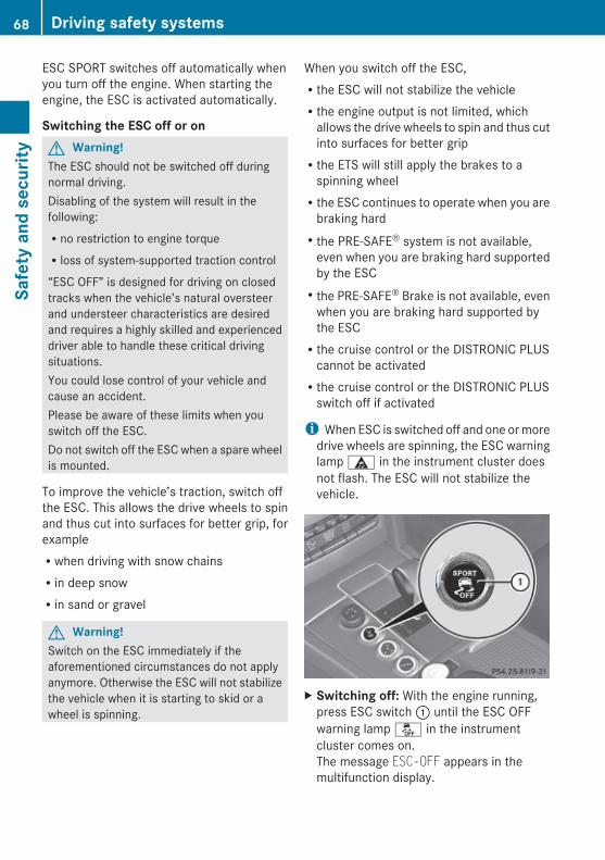
ESC SPORT switches off automatically whenyou turn off the engine. When starting theengine, the ESC is activated automatically.
Switching the ESC off or onG Warning!The ESC should not be switched off duringnormal driving.Disabling of the system will result in thefollowing:Rno restriction to engine torqueRloss of system-supported traction control
“ESC OFF” is designed for driving on closedtracks when the vehicle’s natural oversteerand understeer characteristics are desiredand requires a highly skilled and experienceddriver able to handle these critical drivingsituations.You could lose control of your vehicle andcause an accident.Please be aware of these limits when youswitch off the ESC.Do not switch off the ESC when a spare wheelis mounted.
To improve the vehicle’s traction, switch offthe ESC. This allows the drive wheels to spinand thus cut into surfaces for better grip, forexampleRwhen driving with snow chainsRin deep snowRin sand or gravel
G Warning!Switch on the ESC immediately if theaforementioned circumstances do not applyanymore. Otherwise the ESC will not stabilizethe vehicle when it is starting to skid or awheel is spinning.
When you switch off the ESC,Rthe ESC will not stabilize the vehicleRthe engine output is not limited, which
allows the drive wheels to spin and thus cutinto surfaces for better gripRthe ETS will still apply the brakes to a
spinning wheelRthe ESC continues to operate when you are
braking hardRthe PRE-SAFE® system is not available,
even when you are braking hard supportedby the ESCRthe PRE-SAFE® Brake is not available, even
when you are braking hard supported bythe ESCRthe cruise control or the DISTRONIC PLUS
cannot be activatedRthe cruise control or the DISTRONIC PLUS
switch off if activated
i When ESC is switched off and one or moredrive wheels are spinning, the ESC warninglamp ä in the instrument cluster doesnot flash. The ESC will not stabilize thevehicle.
X Switching off: With the engine running,press ESC switch : until the ESC OFFwarning lamp å in the instrumentcluster comes on.The message ESC-OFF appears in themultifunction display.
68 Driving safety systemsSa
fety
and
sec
urity
212_AKB; 2; 41, en-USd2ureepe, Version: 2.11.8.1
2009-07-17T09:14:21+02:00 - Seite 68
G Warning!When the ESC OFF warning lamp å is on,the ESC is switched off.When the ESC warning lamp ä and theESC OFF warning lamp å are oncontinuously, the ESC is not operational dueto a malfunction.When the ESC is switched off or notoperational, vehicle stability in standarddriving maneuvers is reduced.Adapt your speed and driving to the prevailingroad conditions and to the non-operatingstatus of the ESC.
! Avoid spinning of a drive wheel for anextended period with the ESC switched off.This may cause serious damage to thedrivetrain which is not covered by theMercedes-Benz Limited Warranty.
X Switching on: With the engine running,press ESC switch : briefly.The ESC OFF warning lamp å in theinstrument cluster goes out. The messageESC-ON appears in the multifunctiondisplay.
PRE-SAFE® BrakeThe PRE-SAFE® Brake is available in vehiclesequipped with DISTRONIC PLUS. The PRE-SAFE® Brake can assist you in minimizing therisk of a rear-end collision with a vehicle infront of you. The PRE-SAFE® Brake may alsoreduce the severity of an accident. At speedsabove approximately 20 mph (30 km/h) it willissue a warning when your vehicle isapproaching the preceding vehicle veryquickly. An intermittent acoustic warningsounds and the distance warning lamp ·in the instrument cluster comes on.Due to the system characteristics, warningscould be issued without cause in complexdriving situations.
When the driver and front passenger havefastened their seat belts, the PRE-SAFE®
Brake can alsoRbrake the vehicle within a speed range of
up to 124 mph (200 km/h) automaticallyRactivate preventative occupant safety
measures (PRE-SAFE®) (Y page 53)
G Warning!An intermittent warning sounds and thedistance warning lamp · in the instrumentcluster is illuminated if the PRE-SAFE® Brakecalculates that the distance to the vehicleahead and your vehicle’s current speedindicate that the PRE-SAFE® Brake will not becapable of slowing the vehicle sufficiently tomaintain the preset following distance, whichcreates a danger of a collision.Immediately brake your vehicle to increasethe distance between your vehicle and thevehicle driving in front of you. The warningsound is intended as a final caution that youhave not interceded with your own brakinginputs to avoid a potentially dangeroussituation. Do not wait for the operation of thewarning signal to intercede with your ownbraking, as that will result in potentiallydangerous emergency braking which will notalways result in an impact being avoided.Tailgating increases the risk of an accident.
G Warning!The PRE-SAFE® Brake is a conveniencesystem designed to assist the driver duringvehicle operation. The responsibility for thevehicle speed and the distance to the vehicleahead, including most importantly brakeoperation to assure safe stopping distance,always remains with the driver.Always pay attention to traffic conditionseven while the PRE-SAFE® Brake is switchedon. Otherwise, you may not be able torecognize dangerous situations until it is toolate and could cause an accident resulting inpersonal or fatal injury to you or others.
Driving safety systems 69
Safe
ty a
nd s
ecur
ity
212_AKB; 2; 41, en-USd2ureepe, Version: 2.11.8.1
2009-07-17T09:14:21+02:00 - Seite 69
Z
i USA only:This device has been approved by the FCCas a “Vehicular Radar System”. The radarsensor is intended for use in an automotiveradar system only. Removal, tampering, oraltering of the device will void anywarranties, and is not permitted by theFCC. Do not tamper with, alter, or use inany non-approved way.Any unauthorized modification to thisdevice could void the user’s authority tooperate the equipment.
i Canada only:This device complies with RSS-210 ofIndustry Canada. Operation is subject tothe following two conditions:1. This device may not cause interference,
and2. this device must accept any
interference received, includinginterference that may cause undesiredoperation of the device.
Removal, tampering, or altering of thedevice will void any warranties, and is notpermitted. Do not tamper with, alter, or usein any non-approved way.Any unauthorized modification to thisdevice could void the user’s authority tooperate the equipment.
Using the radar sensors, the PRE-SAFE®
Brake detects obstacles that are in yourdriving path for a sufficient period of time forthe system to recognize it. If you approach avehicle and the PRE-SAFE® Brake hasestablished that the distance to the vehicleahead at your current speed is so close thatthe PRE-SAFE® Brake will not be capable ofslowing the vehicle sufficiently, the systemwill initially warn you visually and acoustically.If you do not apply the brakes yourself ormaneuver around a sensed obstacle, thevehicle will brake lightly automatically. ThePRE-SAFE® system (Y page 53) is activatedwhen the distance to the vehicle ahead at
your current speed is so close that the PRE-SAFE® Brake will not be capable of slowingthe vehicle sufficiently.When the danger of a collision still persistsand you do not brake or acceleratesignificantly, the PRE-SAFE® Brake mayinitiate full application of the brakesautomatically.
G Warning!The PRE-SAFE® Brake will only respond withbrake assistance if it has clearly detected anobject. Detection can be impeded byRdirty or covered sensorsRsnowfall or heavy rainRdisturbance from other radar sourcesRstrong radar reflection such as in parking
garages
The PRE-SAFE® Brake uses radar signals thatare not reflected well by narrow objects andabsorptive materials. For this reason the PRE-SAFE® Brake will not react to persons,animals, and approaching traffic or cross-traffic.The PRE-SAFE® Brake may not detect narrowvehicles driving in front of you, such asmotorcycles and vehicles driving offset fromyour vehicle center.
G Warning!Depending on the vehicle speed, thePRE-SAFE® Brake brakes your vehicle with amaximum of 13 ft/s2 (4 m/s2) before apossible hard stop. This corresponds to about40% of the maximum deceleration ability ofyour vehicle. The driver must apply the brakesadditionally in order to prevent a collision. Theself-acting hard stop will be initiated when theimminent danger of a collision exists, e.g.when an evasive driving maneuver cannotavoid an accident.
70 Driving safety systemsSa
fety
and
sec
urity
212_AKB; 2; 41, en-USd2ureepe, Version: 2.11.8.1
2009-07-17T09:14:21+02:00 - Seite 70

To maintain the proper distance to the vehiclein front of you and thus prevent a rear-endcollision, you must apply the brakes yourself.X Brake the vehicle immediately to avoid a
collision.Under no circumstances should the driverawait the intermittent warning soundbefore braking. Observe the followingwarning note.The intermittent warning sound ceases andthe distance warning lamp · goes outwhen the necessary distance to the vehicleahead is again established.
The PRE-SAFE® Brake can react to stationaryobstacles such as standing or parked vehiclesat road speeds of up to approximately 40 mph(70 km/h).
G Warning!If you do not receive visual or acousticwarning signals, the PRE-SAFE® Brake mayRnot have recognized the collision riskRhave been deactivatedRbe malfunctioning
Apply the brakes yourself to avoid a collision.
The PRE-SAFE® Brake does not always clearlyinterpret complex traffic situations. If a visualand/or acoustic warning is issued in anuncritical driving situation, or if the vehiclebrakes lightly, you can interrupt the PRE-SAFE® Brake maneuver by pressing down allthe way on the accelerator pedal, usingkickdown, or releasing the brake pedal.The PRE-SAFE® Brake maneuver isterminated immediately whenRyou avoid the obstacle by evasive steeringRyou drive less than 9 mph (15 km/h)Ran obstacle can no longer be identified
ahead of youRthe system no longer senses the risk of a
collision
i The PRE-SAFE® Brake will remain passivewhile DISTRONIC PLUS is switched on(Y page 149).
After a hard collision or damage to the frontof the vehicle from an accident, have thesettings and operation of the radar sensorschecked by an authorized Mercedes-BenzCenter.X Activating and deactivating: Activate or
deactivate the PRE-SAFE® Brake using theinstrument cluster control system(Y page 137).After the function has been activated, thePRE-SAFE® Brake indicator Ä appearsin the instrument cluster. When the HOLDfunction is switched on, the PRE-SAFE®
Brake indicator Ä will not appear.In vehicles with Parking Guidance, theautomatic transmission must be in parkposition P for the PRE-SAFE® Brakeindicator Ä to be displayed.
The PRE-SAFE® Brake is deactivated whenthe radar system is switched off. When youswitch off the radar system, the followingfunctions are deactivated:RPRE-SAFE® BrakeRBAS PLUS (Y page 63)RDISTRONIC PLUS (Y page 149)RBlind Spot Assist (Y page 175)
Anti-theft systems
ImmobilizerThe immobilizer prevents unauthorizedpersons from starting your vehicle.When leaving the vehicle, always take theSmartKey with you and lock the vehicle. Theengine can be started by anyone with a validSmartKey that is left inside the vehicle.
Anti-theft systems 71
Safe
ty a
nd s
ecur
ity
212_AKB; 2; 41, en-USd2ureepe, Version: 2.11.8.1
2009-07-17T09:14:21+02:00 - Seite 71
Z
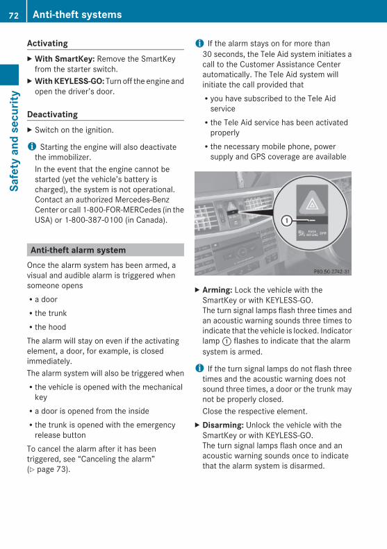
ActivatingX With SmartKey: Remove the SmartKey
from the starter switch.X With KEYLESS-GO: Turn off the engine and
open the driver’s door.
DeactivatingX Switch on the ignition.
i Starting the engine will also deactivatethe immobilizer.In the event that the engine cannot bestarted (yet the vehicle’s battery ischarged), the system is not operational.Contact an authorized Mercedes-BenzCenter or call 1-800-FOR-MERCedes (in theUSA) or 1-800-387-0100 (in Canada).
Anti-theft alarm systemOnce the alarm system has been armed, avisual and audible alarm is triggered whensomeone opensRa doorRthe trunkRthe hoodThe alarm will stay on even if the activatingelement, a door, for example, is closedimmediately.The alarm system will also be triggered whenRthe vehicle is opened with the mechanical
keyRa door is opened from the insideRthe trunk is opened with the emergency
release buttonTo cancel the alarm after it has beentriggered, see “Canceling the alarm”(Y page 73).
i If the alarm stays on for more than30 seconds, the Tele Aid system initiates acall to the Customer Assistance Centerautomatically. The Tele Aid system willinitiate the call provided thatRyou have subscribed to the Tele Aid
serviceRthe Tele Aid service has been activated
properlyRthe necessary mobile phone, power
supply and GPS coverage are available
X Arming: Lock the vehicle with theSmartKey or with KEYLESS-GO.The turn signal lamps flash three times andan acoustic warning sounds three times toindicate that the vehicle is locked. Indicatorlamp : flashes to indicate that the alarmsystem is armed.
i If the turn signal lamps do not flash threetimes and the acoustic warning does notsound three times, a door or the trunk maynot be properly closed.Close the respective element.
X Disarming: Unlock the vehicle with theSmartKey or with KEYLESS-GO.The turn signal lamps flash once and anacoustic warning sounds once to indicatethat the alarm system is disarmed.
72 Anti-theft systemsSa
fety
and
sec
urity
212_AKB; 2; 41, en-USd2ureepe, Version: 2.11.8.1
2009-07-17T09:14:21+02:00 - Seite 72

i Unless you open a door or the trunk withinapproximately 40 seconds after unlockingthe vehicle:RThe vehicle will be locked again.RThe anti-theft alarm system will be
rearmed.
Canceling the alarmTo cancel the alarm, do one of the following:X Insert the SmartKey into the starter switch.X Press button % or & on the
SmartKey.
In vehicles with KEYLESS-GO:X Grasp an outside door handle.
The SmartKey must be within 3 ft (1 m) ofthe vehicle.
X Press the KEYLESS-GO start/stop button.The SmartKey must be inside the vehicle.
Anti-theft systems 73
Safe
ty a
nd s
ecur
ity
212_AKB; 2; 41, en-USd2ureepe, Version: 2.11.8.1
2009-07-17T09:14:21+02:00 - Seite 73
Z

74
212_AKB; 2; 41, en-USd2ureepe, Version: 2.11.8.1
2009-07-17T09:14:21+02:00 - Seite 74

Vehicle equipment .............................. 76Locking and unlocking ....................... 76Starter switch positions ..................... 85Seats .................................................... 87Multifunction steering wheel ............. 93Mirrors ................................................. 94Memory function ................................. 96Lighting ................................................ 97Wipers ................................................ 104Power windows ................................. 105Driving and parking .......................... 109Automatic transmission ................... 114Transfer case .................................... 124Instrument cluster ............................ 125Control system .................................. 126Driving systems ................................ 146Climate control system .................... 180Rear window defroster ..................... 191Power tilt/sliding sunroof ............... 192Panorama roof with power tilt/sliding panel ...................................... 194Loading and storing .......................... 197Useful features ................................. 203
75
Cont
rols
in d
etai
l
212_AKB; 2; 41, en-USd2ureepe, Version: 2.11.8.1
2009-07-17T09:14:21+02:00 - Seite 75
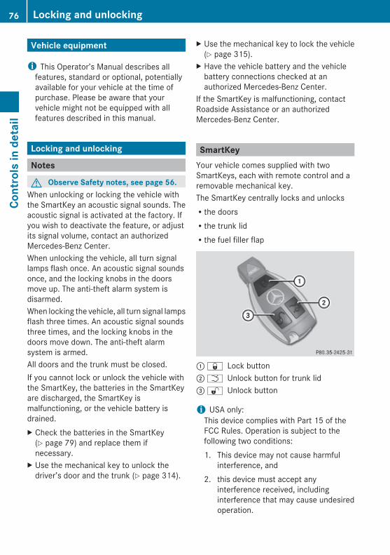
Vehicle equipment
i This Operator’s Manual describes allfeatures, standard or optional, potentiallyavailable for your vehicle at the time ofpurchase. Please be aware that yourvehicle might not be equipped with allfeatures described in this manual.
Locking and unlocking
Notes
G Observe Safety notes, see page 56.When unlocking or locking the vehicle withthe SmartKey an acoustic signal sounds. Theacoustic signal is activated at the factory. Ifyou wish to deactivate the feature, or adjustits signal volume, contact an authorizedMercedes-Benz Center.When unlocking the vehicle, all turn signallamps flash once. An acoustic signal soundsonce, and the locking knobs in the doorsmove up. The anti-theft alarm system isdisarmed.When locking the vehicle, all turn signal lampsflash three times. An acoustic signal soundsthree times, and the locking knobs in thedoors move down. The anti-theft alarmsystem is armed.All doors and the trunk must be closed.If you cannot lock or unlock the vehicle withthe SmartKey, the batteries in the SmartKeyare discharged, the SmartKey ismalfunctioning, or the vehicle battery isdrained.X Check the batteries in the SmartKey
(Y page 79) and replace them ifnecessary.
X Use the mechanical key to unlock thedriver’s door and the trunk (Y page 314).
X Use the mechanical key to lock the vehicle(Y page 315).
X Have the vehicle battery and the vehiclebattery connections checked at anauthorized Mercedes-Benz Center.
If the SmartKey is malfunctioning, contactRoadside Assistance or an authorizedMercedes-Benz Center.
SmartKeyYour vehicle comes supplied with twoSmartKeys, each with remote control and aremovable mechanical key.The SmartKey centrally locks and unlocksRthe doorsRthe trunk lidRthe fuel filler flap
: & Lock button; F Unlock button for trunk lid= % Unlock button
i USA only:This device complies with Part 15 of theFCC Rules. Operation is subject to thefollowing two conditions:1. This device may not cause harmful
interference, and2. this device must accept any
interference received, includinginterference that may cause undesiredoperation.
76 Locking and unlockingCo
ntro
ls in
det
ail
212_AKB; 2; 41, en-USd2ureepe, Version: 2.11.8.1
2009-07-17T09:14:21+02:00 - Seite 76
Any unauthorized modification to thisdevice could void the user’s authority tooperate the equipment.
i Canada only:This device complies with RSS-210 ofIndustry Canada. Operation is subject tothe following two conditions:1. This device may not cause interference,
and2. this device must accept any
interference received, includinginterference that may cause undesiredoperation of the device.
Any unauthorized modification to thisdevice could void the user’s authority tooperate the equipment.
Factory setting X Global unlocking: Press button %.Unless you open a door or the trunk withinapproximately 40 seconds after unlockingthe vehicle:RThe vehicle will be locked again.RThe anti-theft alarm system will be
rearmed.X Global locking: Press button &.
Selective setting If you frequently travel alone, you may wishto reprogramm the SmartKey. Pressingbutton % will then only unlock the driver’sdoor and the fuel filler flap.X Switching on/off: Press and hold buttons% and & simultaneously forapproximately 6 seconds until the batterycheck lamp (Y page 79) flashes twice.
The SmartKey will then function as follows:
X Unlocking driver’s door and fuel filler flap: Press button % once.
X Global unlocking: Press button %twice.
X Global locking: Press button &.
KEYLESS-GOVehicles equipped with KEYLESS-GO comewith two SmartKeys with KEYLESS-GO, eachwith remote control and a removablemechanical key.The KEYLESS-GO function is integrated intothe SmartKey. The validity of the SmartKey ischecked every time you grasp an outside doorhandle.When the SmartKey is valid, your vehicleunlocksRthe doorsRthe trunk lidRthe fuel filler flap
i USA only:This device complies with Part 15 of theFCC Rules. Operation is subject to thefollowing two conditions:1. This device may not cause harmful
interference, and2. this device must accept any
interference received, includinginterference that may cause undesiredoperation.
Any unauthorized modification to thisdevice could void the user’s authority tooperate the equipment.
Locking and unlocking 77
Cont
rols
in d
etai
l
212_AKB; 2; 41, en-USd2ureepe, Version: 2.11.8.1
2009-07-17T09:14:21+02:00 - Seite 77
Z
i Canada only:This device complies with RSS-210 ofIndustry Canada. Operation is subject tothe following two conditions:1. This device may not cause interference,
and2. this device must accept any
interference received, includinginterference that may cause undesiredoperation of the device.
Any unauthorized modification to thisdevice could void the user’s authority tooperate the equipment.
Important notes on using KEYLESS-GO RYou can also use the SmartKey with
KEYLESS-GO like a normal SmartKey(Y page 76).RYou can combine KEYLESS-GO functions
with normal SmartKey functions (e.g.unlocking with KEYLESS-GO and lockingwith button &).RAlways carry the SmartKey with you.RNever store the SmartKey together with
- electronic items such as a mobile phoneor another SmartKey
- metallic objects such as coins or metalfoil
Doing so could impair the function of theKEYLESS-GO system.RTo lock or unlock the vehicle, the SmartKey
must be located outside the vehicle withinapproximately 3 ft (1 m) of a door or thetrunk.RWhen the vehicle has been parked for more
than 72 hours, the KEYLESS-GO function isdeactivated. Pull an outside door handleand switch on the ignition once to activatethe KEYLESS-GO function.RIf the SmartKey is positioned farther away
from the vehicle, the system may no longerrecognize the SmartKey. The vehicle
cannot be locked or the engine started viathe KEYLESS-GO system.RIf the SmartKey is removed from the vehicle
(e.g. if a passenger exits the vehicle withthe SmartKey)- when pressing the KEYLESS-GO start/
stop button or trying to lock the vehiclewith the outside door handle themessage Key Not Detected appears inthe multifunction display
- with the engine running, the red messageKey Not Detected appears in themultifunction display while driving off
Find the SmartKey or change its presentlocation immediately (e.g. place it on thefront passenger seat or insert it in shirtpocket).RIf you have started the engine with the
KEYLESS-GO start/stop button, you canturn it off again by- pressing the KEYLESS-GO start/stop
button- inserting the SmartKey into the starter
switch when the vehicle is at a standstilland the automatic transmission is in parkposition P
RThe vehicle could be inadvertentlyunlocked if the SmartKey is within 3 ft (1 m)of the vehicle and- an outside door handle is splashed with
wateror
- you attempt to clean an outside doorhandle
RRemember that the engine can be startedby anyone with a SmartKey that is leftinside the vehicle.Possibility 1 (One SmartKey in the vehicle,one SmartKey outside the vehicle):If you leave the SmartKey behind whenexiting and locking the vehicle, no messageappears in the multifunction display.
78 Locking and unlockingCo
ntro
ls in
det
ail
212_AKB; 2; 41, en-USd2ureepe, Version: 2.11.8.1
2009-07-17T09:14:21+02:00 - Seite 78

Possibility 2 (One SmartKey in the vehicle,no SmartKey outside the vehicle):When exiting and trying to lock the vehicle,the message Key Detected in Vehicleappears in the multifunction display. Thevehicle will not be locked.
Factory setting X Global unlocking: Grasp an outside door
handle.Unless you open a door or the trunk withinapproximately 40 seconds after unlockingthe vehicle:RThe vehicle will be locked again.RThe anti-theft alarm system will be
rearmed.
X Global locking: Touch outside of a doorhandle :.
Selective setting If you frequently travel alone, you may wishto reprogram the SmartKey. Grasping thedriver’s outside door handle will then onlyunlock the driver’s door and the fuel filler flap.X Switching on/off: Press and hold buttons% and & simultaneously forapproximately 6 seconds until the batterycheck lamp (Y page 79) flashes twice.
KEYLESS-GO will then function as follows:
X Unlocking driver’s door and fuel filler flap: Grasp the driver’s outside doorhandle.
X Global unlocking: Grasp any outside doorhandle other than the driver’s outside doorhandle.
X Global locking: Touch outside of a doorhandle :.
Checking SmartKey batteries
X Press button & or % on theSmartKey.Battery check lamp : comes on briefly toindicate that the SmartKey batteries are inorder.
If the battery check lamp does not come onbriefly during check, the SmartKey batteriesare discharged.X Replace the batteries (Y page 317).
i You can obtain the required batteries atany authorized Mercedes-Benz Center.
i If the batteries are checked within signalrange of the vehicle, pressing button& or % will lock or unlock the vehicleaccordingly.
Loss of the SmartKeyIf you lose your SmartKey or mechanical key,you should do the following:
Locking and unlocking 79
Cont
rols
in d
etai
l
212_AKB; 2; 41, en-USd2ureepe, Version: 2.11.8.1
2009-07-17T09:14:21+02:00 - Seite 79
Z

X Have the SmartKey deactivated by anauthorized Mercedes-Benz Center.
X Report the loss of the SmartKey or themechanical key to your car insurancecompany immediately.
X Have the mechanical lock replaced ifnecessary.
Any authorized Mercedes-Benz Center will beglad to supply you with a replacement. Forinformation on replacing the SmartKey, see“Replacing the SmartKey” (Y page 80).
Replacing the SmartKeyOnly you, or someone authorized by you canorder a replacement key from any Mercedes-Benz Center. In order to do so, the Mercedes-Benz Center will require proof of identity andvehicle ownership with original documents,including the following:If you are the current owner of the vehicle:Rthe vehicle’s current state registrationRa current identity card, passport, or drivers
licenseIf you are an authorized person:Rthe vehicle’s current state registrationRa current identity card, passport, or drivers
license for the authorized individualRsigned and dated authorization from the
owner of the vehicle for which the key isbeing requested
i Duplicated or photocopieddocumentation will not be accepted.
Activating the keyOnce you, or an authorized person, hasprovided the appropriate documents, theMercedes-Benz Center will need tosynchronize the key to your vehicle before itcan be used. In order to do so, the Mercedes-Benz Center need access to your vehicle.
Opening the doors from the insideYou can open a door from the inside evenwhen it is locked unless it is secured with thechild safety lock (Y page 60).Open door only when conditions are safe todo so.
Example illustration driver’s door
If the vehicle has previously been locked withthe SmartKey or with KEYLESS-GO, openinga door from the inside will trigger the anti-theft alarm system.To cancel the alarm, see (Y page 73).X Front doors: Pull on inside door
handle ; on the respective front door.If the door was locked, locking knob : willmove up.
X Rear doors: Pull up locking knob on therespective rear door to unlock door.
Automatic central lockingThe doors and the trunk lock automaticallywhen the vehicle is set into motion.You can open a locked front door from theinside. Open door only when conditions aresafe to do so.The doors are designed to unlockautomatically after an accident if the force ofthe impact exceeds a preset threshold.The vehicle locks automatically when theignition is switched on and the wheels areturning at a vehicle speed of above 9 mph(15 km/h). You could therefore lock yourself
80 Locking and unlockingCo
ntro
ls in
det
ail
212_AKB; 2; 41, en-USd2ureepe, Version: 2.11.8.1
2009-07-17T09:14:21+02:00 - Seite 80

out when the vehicle is pushed or towed or ison a test stand.
X Switching off: Press and hold centralunlocking switch : until an acoustic signalsounds.
X Switching on: Press and hold centrallocking switch ; until an acoustic signalsounds.
i If you press and hold either switch and noacoustic signal sounds, the respectivesetting has already been selected.
i You can also switch on or off theautomatic central locking using the controlsystem (Y page 144).
Locking and unlocking from the inside
G Observe Safety notes, see page 56.You can lock or unlock the vehicle from theinside using the central locking or unlockingswitch. This can be useful, for example, if youwant to lock the vehicle before starting todrive.The central locking or unlocking switch doesnot lock or unlock the fuel filler flap.
X Locking: Press central locking switch ;.When all doors are closed, the vehiclelocks.
X Unlocking: Press central unlockingswitch :.
You can open a locked front door from theinside. Open door only when conditions aresafe to do so.If the vehicle was previously locked with thecentral locking switchRand the SmartKey is set to factory settings,
the complete vehicle is unlocked when afront door is opened from the insideRand the SmartKey is set to selective
settings, only the front door opened fromthe inside is unlocked
If the vehicle has been locked centrally withthe SmartKey or with KEYLESS-GO, it will notunlock using the central unlocking switch.
Opening the trunk
G Warning!Make sure the trunk is closed when the engineis running and while driving. Among otherdangers, deadly carbon monoxide (CO) gasesmay enter vehicle interior resulting inunconsciousness and death.
! When you open the trunk, the trunk lidswings open upwards. Always make surethere is sufficient overhead clearance.
Locking and unlocking 81
Cont
rols
in d
etai
l
212_AKB; 2; 41, en-USd2ureepe, Version: 2.11.8.1
2009-07-17T09:14:21+02:00 - Seite 81
Z

You can open the trunk when the vehicle isstationary.A minimum height clearance of 5.78 ft(1.76 m) is required to open the trunk lid.
Opening the trunk from the outside
X Press and hold button F (Y page 76) onthe SmartKey until the trunk unlocks andbegins to open.
orX Pull on handle :.
In vehicles without KEYLESS-GO: Thevehicle must be unlocked.
If the trunk does not open, it is still lockedseparately (Y page 85).
Opening the trunk from the inside
Example illustration: Vehicles with trunk opening/closing system
X Pull remote trunk opening switch : untilthe trunk begins to open.
If the trunk does not open, it is still lockedseparately (Y page 85).
Closing the trunk
G Warning!Make sure the trunk is closed when the engineis running and while driving. Among otherdangers, deadly carbon monoxide (CO) gasesmay enter vehicle interior resulting inunconsciousness and death.
G Warning!To prevent possible personal injury, alwayskeep hands and fingers away from the trunkopening when closing the trunk lid. Beespecially careful when small children arearound.
G Observe Safety notes, see page 56.Do not leave the SmartKey in the open trunk.You may lock yourself out.If the vehicle was previously locked centrallywith the SmartKey or KEYLESS-GO, the trunklid will lock automatically when closed. Allturn signal lamps flash three times and anacoustic signal sounds three times to confirmlocking.
Closing the trunk from the outside manually
X Lower trunk lid by pulling on handle : orhandle ; firmly.
X Close trunk with hands placed flat on trunklid.
82 Locking and unlockingCo
ntro
ls in
det
ail
212_AKB; 2; 41, en-USd2ureepe, Version: 2.11.8.1
2009-07-17T09:14:21+02:00 - Seite 82

Closing the trunk from the inside automatically
G Warning!Maintain sight of the area around the rear ofthe vehicle while operating the trunk lid withthe door mounted switch. Monitor the closingprocedure carefully to make sure no one is indanger of being injured.To interrupt the closing procedure, releasethe door mounted remote trunk opening/closing switch again.Even with the SmartKey removed from thestarter switch or the SmartKey with KEYLESS-GO removed from the vehicle, the remotetrunk opening/closing switch can beoperated. Therefore, do not leave childrenunattended in the vehicle, or with access toan unlocked vehicle. A child’s unsupervisedaccess to a vehicle could result in an accidentand/or serious personal injury.
In vehicles with trunk opening/closingsystem you can close the trunk from theinside using the remote trunk opening/closing switch.If the trunk lid comes into contact with anobject while closing, the closing procedure isstopped and the trunk lid reopens slightly.This will happen only while the trunk is in itsupper motion sequence. Check if luggage hasbeen piled too high, for example.
X Press and hold remote trunk opening/closing switch : until the trunk is closed.
X Interrupting the closing procedure:Release remote trunk opening/closingswitch :.
Closing the trunk from the outside automatically
G Warning!Monitor the closing procedure carefully tomake sure no one is in danger of beinginjured. To prevent possible personal injury,always keep hands and fingers away from thetrunk opening when closing the trunk lid. Beespecially careful when small children arearound. To stop the closing procedure, do oneof the following:RPress button F on the SmartKey.RPress the remote trunk opening/closing
switch (on the driver’s door).RPress the trunk closing switch.RPress the KEYLESS-GO locking/closing
switch.RPull the trunk lid handle.
Even with the SmartKey removed from thestarter switch or the SmartKey with KEYLESS-GO removed from the vehicle, the remotetrunk opening/closing switch can beoperated. Therefore, do not leave childrenunattended in the vehicle, or with access toan unlocked vehicle. A child’s unsupervisedaccess to a vehicle could result in an accidentand/or serious personal injury.
In vehicles with trunk opening/closingsystem you can close the trunk from theoutside using the trunk closing switch.
Locking and unlocking 83
Cont
rols
in d
etai
l
212_AKB; 2; 41, en-USd2ureepe, Version: 2.11.8.1
2009-07-17T09:14:21+02:00 - Seite 83
Z

Example: Vehicles with KEYLESS-GO
X Press trunk closing switch : briefly.If the trunk lid comes into contact with anobject while closing, the closing procedure isstopped and the trunk lid reopens slightly.This will happen only while the trunk is in itsupper motion sequence. Check if luggage hasbeen piled too high, for example.
Closing the trunk and locking vehicle from outsideThis section applies to vehicles with trunkopening/closing system and KEYLESS-GOonly. You can close the trunk and lock thevehicle simultaneously from the outside usingthe KEYLESS-GO locking/closing switch.
X Make sure you have the SmartKey withKEYLESS-GO with you.
X Press KEYLESS-GO locking/closingswitch : briefly.With all doors closed:
RThe locking knobs in the doors movedown.RThe trunk lid starts to close
automatically.RAll turn signal lamps flash three times to
confirm locking once the trunk hasclosed completely.RAn acoustic signal sounds three times.RThe anti-theft alarm system is armed.
If the trunk lid comes into contact with anobject while closing, the closing procedure isstopped and the trunk lid reopens slightly.This will happen only while the trunk is in itsupper motion sequence. Check if luggage hasbeen piled too high, for example.
Trunk lid emergency releaseThe trunk lid can be opened from inside thetrunk with the emergency release button.
X Briefly press emergency releasebutton :.The trunk lid unlocks and opens.
The emergency release button unlocks andopens the trunk while the vehicle is standingstill or in motion.Illumination of the emergency release button:RThe button flashes for 30 minutes after
opening the trunk.RThe button flashes for 60 minutes after
closing the trunk.
84 Locking and unlockingCo
ntro
ls in
det
ail
212_AKB; 2; 41, en-USd2ureepe, Version: 2.11.8.1
2009-07-17T09:14:21+02:00 - Seite 84

The emergency release button does not openthe trunk, if the vehicle battery is dischargedor disconnected.
Valet lockingYou can lock the trunk separately with themechanical key. This denies unauthorizedaccess to the trunk, e.g. when you valet parkthe vehicle.X Leave only the SmartKey less its
mechanical key with the vehicle.
X Valet locking: Close the trunk.X Remove the mechanical key from the
SmartKey (Y page 315).X Insert the mechanical key in the trunk lid
lock.X Turn the mechanical key clockwise to
position 2 and remove the mechanicalkey in that position to lock the trunk.
The trunk remains locked even when thevehicle is centrally unlocked.You can then only open the trunk with themechanical key.X Canceling: Insert the mechanical key in
the trunk lid lock.X Turn the mechanical key counterclockwise
to neutral position 1 and remove themechanical key in that position to unlockthe trunk.You can now open the trunk.
Starter switch positions
SmartKey
G Observe Safety notes, see page 56.
g For removing SmartKey (gear selectorlever must be in park position P)
1 Power supply for some electricalconsumers, e.g. wipers
2 Ignition (power supply for all electricalconsumers) and driving position
3 Starting position
When you switch on the ignition, all lamps inthe instrument cluster come on. The low-beam headlamp indicator lamp, high-beamheadlamp indicator lamp, turn signalindicator lamps, and the indicator lamps forthe fog lamps will only come on if activated.If a lamp in the instrument cluster fails tocome on when the ignition is switched on,have it checked and replaced if necessary. Ifa lamp in the instrument cluster remains onafter starting the engine or comes on whiledriving, refer to “Lamps in instrument cluster”(Y page 304).If the SmartKey is left in starter switchposition 0 for an extended period of time, itcan no longer be turned in the starter switch.In this case, the steering is locked. To unlock,remove SmartKey from the starter switch andreinsert.The steering is locked when the SmartKey isremoved from the starter switch.
Starter switch positions 85
Cont
rols
in d
etai
l
212_AKB; 2; 41, en-USd2ureepe, Version: 2.11.8.1
2009-07-17T09:14:21+02:00 - Seite 85
Z
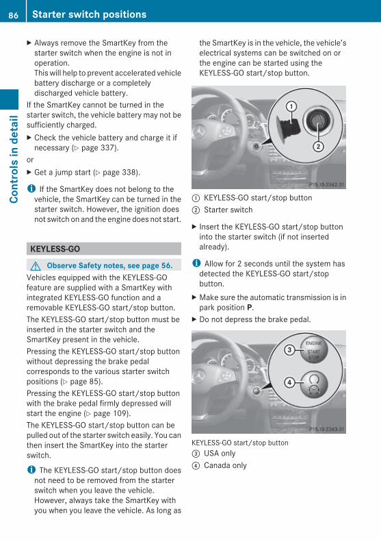
X Always remove the SmartKey from thestarter switch when the engine is not inoperation.This will help to prevent accelerated vehiclebattery discharge or a completelydischarged vehicle battery.
If the SmartKey cannot be turned in thestarter switch, the vehicle battery may not besufficiently charged.X Check the vehicle battery and charge it if
necessary (Y page 337).orX Get a jump start (Y page 338).
i If the SmartKey does not belong to thevehicle, the SmartKey can be turned in thestarter switch. However, the ignition doesnot switch on and the engine does not start.
KEYLESS-GO
G Observe Safety notes, see page 56.Vehicles equipped with the KEYLESS-GOfeature are supplied with a SmartKey withintegrated KEYLESS-GO function and aremovable KEYLESS-GO start/stop button.The KEYLESS-GO start/stop button must beinserted in the starter switch and theSmartKey present in the vehicle.Pressing the KEYLESS-GO start/stop buttonwithout depressing the brake pedalcorresponds to the various starter switchpositions (Y page 85).Pressing the KEYLESS-GO start/stop buttonwith the brake pedal firmly depressed willstart the engine (Y page 109).The KEYLESS-GO start/stop button can bepulled out of the starter switch easily. You canthen insert the SmartKey into the starterswitch.
i The KEYLESS-GO start/stop button doesnot need to be removed from the starterswitch when you leave the vehicle.However, always take the SmartKey withyou when you leave the vehicle. As long as
the SmartKey is in the vehicle, the vehicle’selectrical systems can be switched on orthe engine can be started using theKEYLESS-GO start/stop button.
: KEYLESS-GO start/stop button; Starter switch
X Insert the KEYLESS-GO start/stop buttoninto the starter switch (if not insertedalready).
i Allow for 2 seconds until the system hasdetected the KEYLESS-GO start/stopbutton.
X Make sure the automatic transmission is inpark position P.
X Do not depress the brake pedal.
KEYLESS-GO start/stop button= USA only? Canada only
86 Starter switch positionsCo
ntro
ls in
det
ail
212_AKB; 2; 41, en-USd2ureepe, Version: 2.11.8.1
2009-07-17T09:14:21+02:00 - Seite 86

Position 0Before you press the KEYLESS-GO start/stopbutton, the vehicle’s on-board electronicshave status 0 (as with SmartKey removed).
Position 1X Press the KEYLESS-GO start/stop button
once.This supplies power for some electricalconsumers, e.g. wipers.
i When you now open the driver’s door, thepower supply is switched off.
Ignition (or position 2) X Press the KEYLESS-GO start/stop button
twice.This supplies power for all electricalconsumers.When you switch on the ignition, all lampsin the instrument cluster come on. The low-beam headlamp indicator lamp, high-beamheadlamp indicator lamp, turn signalindicator lamps, and the indicator lamps forthe fog lamps will only come on if activated.If a lamp in the instrument cluster fails tocome on when the ignition is switched on,have it checked and replaced if necessary.If a lamp in the instrument cluster remainson after starting the engine or comes onwhile driving, refer to “Lamps in instrumentcluster” (Y page 304).
i When you now press the KEYLESS-GOstart/stop button once and the driver’sdoor is open, the power supply is switchedoff.
Seats
Safety notes
G Warning!In order to avoid possible loss of vehiclecontrol the following must be done before thevehicle is put into motion:Rseat adjustmentRhead restraint adjustmentRsteering wheel adjustmentRrear view mirror adjustmentRfastening of seat belts
G Warning!Do not adjust the driver’s seat while driving.Adjusting the seat while driving could causethe driver to lose control of the vehicle.Never ride in a moving vehicle with the seatbackrest in an excessively reclined position asthis can be dangerous. You could slide underthe seat belt in a collision. If you slide underit, the seat belt would apply force at theabdomen or neck. That could cause seriousor fatal injuries. The seat backrest and seatbelts provide the best restraint when thewearer is in a position that is as upright aspossible and seat belts are properlypositioned on the body.
G Warning!Your seat must be adjusted so that you cancorrectly fasten your seat belt.Observe the following points:RAdjust the seat backrest until your arms are
slightly angled when holding the steeringwheel.RAdjust the seat to a comfortable seating
position that still allows you to reach theaccelerator/brake pedal safely. Theposition should be as far back as possiblewith the driver still able to operate thecontrols properly.
Seats 87
Cont
rols
in d
etai
l
212_AKB; 2; 41, en-USd2ureepe, Version: 2.11.8.1
2009-07-17T09:14:21+02:00 - Seite 87
Z
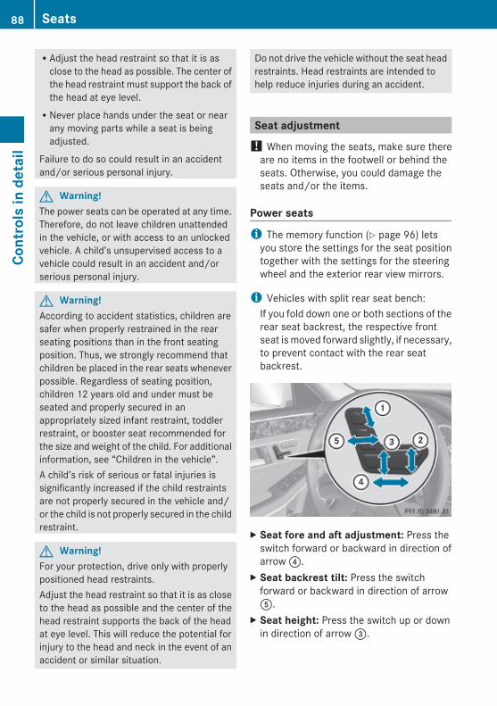
RAdjust the head restraint so that it is asclose to the head as possible. The center ofthe head restraint must support the back ofthe head at eye level.RNever place hands under the seat or near
any moving parts while a seat is beingadjusted.
Failure to do so could result in an accidentand/or serious personal injury.
G Warning!The power seats can be operated at any time.Therefore, do not leave children unattendedin the vehicle, or with access to an unlockedvehicle. A child’s unsupervised access to avehicle could result in an accident and/orserious personal injury.
G Warning!According to accident statistics, children aresafer when properly restrained in the rearseating positions than in the front seatingposition. Thus, we strongly recommend thatchildren be placed in the rear seats wheneverpossible. Regardless of seating position,children 12 years old and under must beseated and properly secured in anappropriately sized infant restraint, toddlerrestraint, or booster seat recommended forthe size and weight of the child. For additionalinformation, see “Children in the vehicle”.A child’s risk of serious or fatal injuries issignificantly increased if the child restraintsare not properly secured in the vehicle and/or the child is not properly secured in the childrestraint.
G Warning!For your protection, drive only with properlypositioned head restraints.Adjust the head restraint so that it is as closeto the head as possible and the center of thehead restraint supports the back of the headat eye level. This will reduce the potential forinjury to the head and neck in the event of anaccident or similar situation.
Do not drive the vehicle without the seat headrestraints. Head restraints are intended tohelp reduce injuries during an accident.
Seat adjustment! When moving the seats, make sure there
are no items in the footwell or behind theseats. Otherwise, you could damage theseats and/or the items.
Power seats i The memory function (Y page 96) lets
you store the settings for the seat positiontogether with the settings for the steeringwheel and the exterior rear view mirrors.
i Vehicles with split rear seat bench:If you fold down one or both sections of therear seat backrest, the respective frontseat is moved forward slightly, if necessary,to prevent contact with the rear seatbackrest.
X Seat fore and aft adjustment: Press theswitch forward or backward in direction ofarrow ?.
X Seat backrest tilt: Press the switchforward or backward in direction of arrowA.
X Seat height: Press the switch up or downin direction of arrow =.
88 SeatsCo
ntro
ls in
det
ail
212_AKB; 2; 41, en-USd2ureepe, Version: 2.11.8.1
2009-07-17T09:14:21+02:00 - Seite 88

X Seat cushion tilt: Press the switch up ordown in direction of arrow ; until yourupper legs are lightly supported.
X Head restraint height: Press the switchup or down in direction of arrow :.
Head restraint fore and aft adjustment
X Push or pull on the lower edge of the headrestraint cushion to the desired position.
Comfort head restraint G Warning!When folding back the side cushions, neverreach between the side cushion and themounting post. You could otherwise betrapped.
You can adjust the side cushions of the headrestraints individually.X Adjusting side cushions: Pull or push side
cushions : into desired position.X Adjusting forward or backward: Pull or
push head restraint in direction ofarrow ;.
Lumbar supportYou can adjust the contour of the front seat’slumbar support to help enhance support toyour spine.
X Curvature position: Use button : tomove the curvature up and button = tomove it down.
X Degree of curvature: Use button ; tolessen the curvature and button ? toincrease it.
Rear seat head restraints
G Warning!For safety reasons, always drive with the rearhead restraints in the upright position whenthe rear seats are occupied.Keep the area around head restraints clear ofarticles (e.g. clothing) to not obstruct thefolding operation of the head restraints.
G Warning!For your protection, drive only with properlypositioned head restraints.Adjust the head restraint in such a way that itis as close to the head as possible and thecenter of the head restraint supports the backof the head at eye level. This will reduce thepotential for injury to the head and neck in theevent of an accident or similar situation.With a rear seat occupied, make sure to movethe respective head restraint up from the
Seats 89
Cont
rols
in d
etai
l
212_AKB; 2; 41, en-USd2ureepe, Version: 2.11.8.1
2009-07-17T09:14:21+02:00 - Seite 89
Z

lowest non-use position and have theoccupant adjust the head restraint properly.Do not drive the vehicle without the seat headrestraints installed when the rear seats areoccupied. Head restraints are intended tohelp reduce injuries during an accident.
G Warning!Make sure the rear seat head restraintsengage when placing them upright manually.Otherwise their protective function cannot beensured.The back of the head will not be supported inthe event of a collision. That could causeserious or even fatal injuries. Rear seatoccupants can be seriously injured or killed.
Lowering rear seat head restraintsThe rear seat head restraints can be loweredfor increased visibility.
X Press button :.The rear seat head restraints are lowered.
Rear seat head restraint height adjustment
X Raising: Pull head restraint upward to thedesired position.
X Lowering: Press release button : andpush down on head restraint.
Rear seat head restraint fore and aft adjustment
X Adjust the head restraint to the desiredposition by pushing or pulling on the upperedge of the head restraint cushion.
Rear seat head restraints, removing and installing (vehicles with split foldable rear seat backrest)i The rear seat head restraints cannot be
removed on vehicles which do not have thesplit foldable rear seat backrest.
90 SeatsCo
ntro
ls in
det
ail
212_AKB; 2; 41, en-USd2ureepe, Version: 2.11.8.1
2009-07-17T09:14:21+02:00 - Seite 90
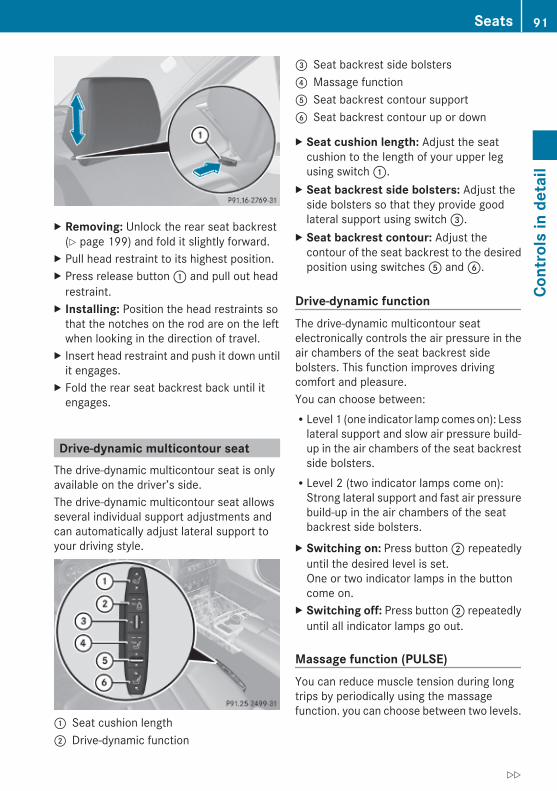
X Removing: Unlock the rear seat backrest(Y page 199) and fold it slightly forward.
X Pull head restraint to its highest position.X Press release button : and pull out head
restraint.X Installing: Position the head restraints so
that the notches on the rod are on the leftwhen looking in the direction of travel.
X Insert head restraint and push it down untilit engages.
X Fold the rear seat backrest back until itengages.
Drive-dynamic multicontour seatThe drive-dynamic multicontour seat is onlyavailable on the driver’s side.The drive-dynamic multicontour seat allowsseveral individual support adjustments andcan automatically adjust lateral support toyour driving style.
: Seat cushion length; Drive-dynamic function
= Seat backrest side bolsters? Massage functionA Seat backrest contour supportB Seat backrest contour up or down
X Seat cushion length: Adjust the seatcushion to the length of your upper legusing switch :.
X Seat backrest side bolsters: Adjust theside bolsters so that they provide goodlateral support using switch =.
X Seat backrest contour: Adjust thecontour of the seat backrest to the desiredposition using switches A and B.
Drive-dynamic functionThe drive-dynamic multicontour seatelectronically controls the air pressure in theair chambers of the seat backrest sidebolsters. This function improves drivingcomfort and pleasure.You can choose between:RLevel 1 (one indicator lamp comes on): Less
lateral support and slow air pressure build-up in the air chambers of the seat backrestside bolsters.RLevel 2 (two indicator lamps come on):
Strong lateral support and fast air pressurebuild-up in the air chambers of the seatbackrest side bolsters.
X Switching on: Press button ; repeatedlyuntil the desired level is set.One or two indicator lamps in the buttoncome on.
X Switching off: Press button ; repeatedlyuntil all indicator lamps go out.
Massage function (PULSE)You can reduce muscle tension during longtrips by periodically using the massagefunction. you can choose between two levels.
Seats 91
Cont
rols
in d
etai
l
212_AKB; 2; 41, en-USd2ureepe, Version: 2.11.8.1
2009-07-17T09:14:21+02:00 - Seite 91
Z
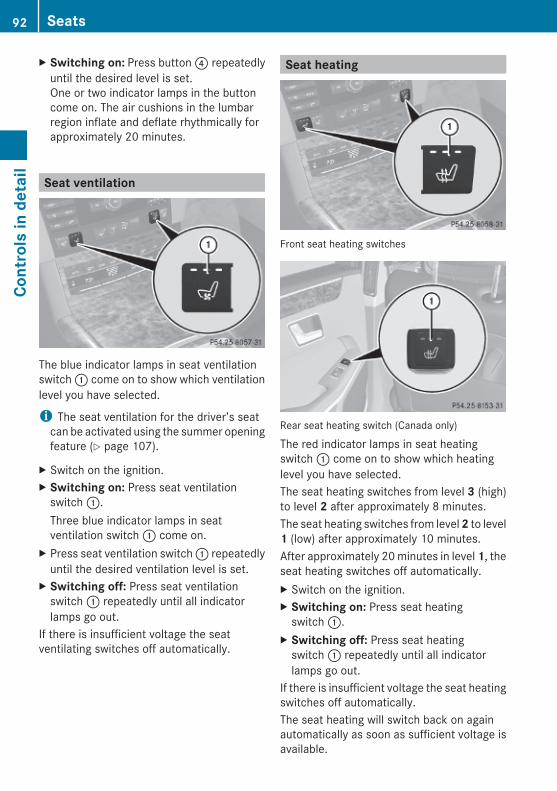
X Switching on: Press button ? repeatedlyuntil the desired level is set.One or two indicator lamps in the buttoncome on. The air cushions in the lumbarregion inflate and deflate rhythmically forapproximately 20 minutes.
Seat ventilation
The blue indicator lamps in seat ventilationswitch : come on to show which ventilationlevel you have selected.
i The seat ventilation for the driver’s seatcan be activated using the summer openingfeature (Y page 107).
X Switch on the ignition.X Switching on: Press seat ventilation
switch :.Three blue indicator lamps in seatventilation switch : come on.
X Press seat ventilation switch : repeatedlyuntil the desired ventilation level is set.
X Switching off: Press seat ventilationswitch : repeatedly until all indicatorlamps go out.
If there is insufficient voltage the seatventilating switches off automatically.
Seat heating
Front seat heating switches
Rear seat heating switch (Canada only)
The red indicator lamps in seat heatingswitch : come on to show which heatinglevel you have selected.The seat heating switches from level 3 (high)to level 2 after approximately 8 minutes.The seat heating switches from level 2 to level1 (low) after approximately 10 minutes.After approximately 20 minutes in level 1, theseat heating switches off automatically.X Switch on the ignition.X Switching on: Press seat heating
switch :.X Switching off: Press seat heating
switch : repeatedly until all indicatorlamps go out.
If there is insufficient voltage the seat heatingswitches off automatically.The seat heating will switch back on againautomatically as soon as sufficient voltage isavailable.
92 SeatsCo
ntro
ls in
det
ail
212_AKB; 2; 41, en-USd2ureepe, Version: 2.11.8.1
2009-07-17T09:14:21+02:00 - Seite 92
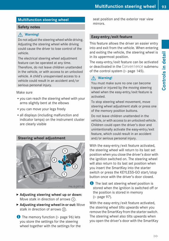
Multifunction steering wheel
Safety notes
G Warning!Do not adjust the steering wheel while driving.Adjusting the steering wheel while drivingcould cause the driver to lose control of thevehicle.The electrical steering wheel adjustmentfeature can be operated at any time.Therefore, do not leave children unattendedin the vehicle, or with access to an unlockedvehicle. A child’s unsupervised access to avehicle could result in an accident and/orserious personal injury.
Make sureRyou can reach the steering wheel with your
arms slightly bent at the elbowsRyou can move your legs freelyRall displays (including malfunction and
indicator lamps) on the instrument clusterare clearly visible
Steering wheel adjustment
X Adjusting steering wheel up or down:Move stalk in direction of arrows :.
X Adjusting steering wheel in or out: Movestalk in direction of arrows ;.
i The memory function (Y page 96) letsyou store the settings for the steeringwheel together with the settings for the
seat position and the exterior rear viewmirrors.
Easy-entry/exit featureThis feature allows the driver an easier entryinto and exit from the vehicle. When enteringand exiting the vehicle, the steering wheel isin its uppermost position.The easy-entry/exit feature can be activatedor deactivated in the Convenience submenuof the control system (Y page 145).
G Warning!You must make sure no one can becometrapped or injured by the moving steeringwheel when the easy-entry/exit feature isactivated.To stop steering wheel movement, movesteering wheel adjustment stalk or press oneof the memory position buttons.Do not leave children unattended in thevehicle, or with access to an unlocked vehicle.Children could open the driver’s door andunintentionally activate the easy-entry/exitfeature, which could result in an accidentand/or serious personal injury.
With the easy-entry/exit feature activated,the steering wheel will return to its last setposition when you close the driver’s door withthe ignition switched on. The steering wheelwill also return to its last set position whenyou insert the SmartKey into the starterswitch or press the KEYLESS-GO start/stopbutton once with the driver’s door closed.
i The last set steering wheel position isstored when the ignition is switched off orthe position is stored in memory(Y page 97).
With the easy-entry/exit feature activated,the steering wheel tilts upwards when youremove the SmartKey from the starter switch.The steering wheel also tilts upwards whenyou open the driver’s door with the SmartKey
Multifunction steering wheel 93
Cont
rols
in d
etai
l
212_AKB; 2; 41, en-USd2ureepe, Version: 2.11.8.1
2009-07-17T09:14:21+02:00 - Seite 93
Z

in starter switch position 0 or 1 or theKEYLESS-GO start/stop button in position 1.
i When the current position for the steeringwheel is in the uppermost tilt position, thesteering wheel will no longer be able tomove upward when the easy-entry/exitfeature is activated.The adjustment procedure is brieflyinterrupted when the engine is started.
G Warning!Let the system complete the adjustmentprocedure before setting the vehicle inmotion. All steering wheel adjustment mustbe completed before setting the vehicle inmotion. Driving off with the steering wheelstill adjusting could cause the driver to losecontrol of the vehicle.
Crash-responsive exit aidWhen you open the driver’s door after anaccident has occurred, the steering columnmoves up. The position of the SmartKey in thestarter switch is insignificant. This functionfacilitates exiting as well as rescue of vehicleoccupants.The crash-responsive exit aid can only betriggered when the easy-entry/exit feature isactivated via the control system.
Heated steering wheelThe steering wheel heating warms up theleather area of the steering wheel.
X Switch on the ignition.X Switching on: Turn switch at the tip of the
stalk in direction of arrow :.Indicator lamp = comes on.
i The steering wheel heating may besuspended temporarily. However, indicatorlamp = remains on. The steering wheelheating is suspended when thetemperature of the vehicle interior is above86‡ (30†). It is also suspended when thetemperature of the steering wheel is above95‡ (35†).
X Switching off: Turn switch at the tip ofstalk in direction of arrow ;.Indicator lamp = goes out.
i Indicator lamp = flashes or goes out incase of power surge or undervoltage or ifthe steering wheel heating malfunctions.
i The steering wheel heating switches offautomatically when you remove theSmartKey from the starter switch or, onvehicles with KEYLESS-GO, when youswitch off the ignition and open the driver’sdoor.
For more information on the steering wheel,see “Multifunction steering wheel”(Y page 126).
Mirrors
NotesAdjust the interior and exterior rear viewmirrors before driving so that you have a goodview of the road and traffic conditions.
Interior rear view mirrorX Adjust the interior rear view mirror
manually.
94 MirrorsCo
ntro
ls in
det
ail
212_AKB; 2; 41, en-USd2ureepe, Version: 2.11.8.1
2009-07-17T09:14:21+02:00 - Seite 94

Exterior rear view mirrors
G Warning!Exercise care when using the passenger-sideexterior rear view mirror. The mirror surfaceis convex (outwardly curved surface for awider field of view). Objects in mirror arecloser than they appear. Check your interiorrear view mirror and glance over yourshoulder before changing lanes.
i You can store the settings for the exteriorrear view mirror position with the memoryfunction (Y page 96).
X Switch on the ignition.X Press button : for the driver’s side
exterior rear view mirror or button ; forthe passenger-side exterior rear viewmirror.The indicator lamp in the respective buttoncomes on.If you do not make adjustments to theselected exterior rear view mirror within15 seconds, the indicator lamp goes out.You will then have to select the desiredexterior rear view mirror again beforeadjustments can be made. Adjustmentscan only be made with the indicator lampfor the respective exterior rear view mirrorbutton illuminated.
X Press adjustment button = up, down, leftor right according to the desired setting.
! If an exterior rear view mirror was forciblyhit from the front, manually snap it backinto place.
i At low ambient temperatures, the exteriorrear view mirrors will be heatedautomatically.
Auto-dimming rear view mirrorsThe exterior rear view mirror on the driver’sside and the interior rear view mirror willrespond automatically to glare when theignition is switched on and incoming lightfrom headlamps falls on the sensor in theinterior rear view mirror.The rear view mirrors will not react if theautomatic transmission is set to reverse gearR or the interior lighting is switched on.
G Warning!The auto dimming function does not react ifincoming light is not aimed directly at sensorsin the interior rear view mirror.The interior rear view mirror and the exteriorrear view mirror on the driver’s side do notreact, for example, if the rear windowsunshade is in raised position.Light hitting the mirror(s) at certain angles(incident light) could blind you. As a result,you may not be able to observe trafficconditions and could cause an accident.
Exterior rear view mirror parking position
To assist during parking maneuvers, you canset the passenger-side exterior rear viewmirror so that you can see the rear wheel andthe road curb.
Setting and storing the parking position
Mirrors 95
Cont
rols
in d
etai
l
212_AKB; 2; 41, en-USd2ureepe, Version: 2.11.8.1
2009-07-17T09:14:21+02:00 - Seite 95
Z

X Switch on the ignition.X Press button ;, to select the passenger-
side exterior rear view mirror.X Shift the automatic transmission into
reverse gear R.The passenger-side exterior rear viewmirror moves to the preset parkingposition.
X Adjust the passenger-side exterior rearview mirror with adjustment button = sothat you see the rear wheel and the roadcurb.The exterior rear view mirror parkingposition is stored.
You can also store the parking position usingthe memory button M ?:X Switch on the ignition.X Press button ;, to select the passenger-
side exterior rear view mirror.X Adjust the passenger-side exterior rear
view mirror with adjustment button = sothat you see the rear wheel and the roadcurb.
X Press memory button M ? and within3 seconds, press one of the arrows ofadjustment button =.The parking position is stored if the exteriorrear view mirror does not move.
i If the exterior rear view mirror does move,repeat the above steps. After the setting isstored, you can move the exterior rear viewmirror again.
Calling up the parking positionX Switch on the ignition.X Press button ;, to select the passenger-
side exterior rear view mirror.X Shift the automatic transmission into
reverse gear R.The passenger-side exterior rear viewmirror moves to the stored parkingposition.
The passenger-side exterior rear view mirrorreturns to its previously stored drivingpositionR10 seconds after you have put the gear
selector lever out of reverse gear RRimmediately once your vehicle exceeds a
speed of approximately 6 mph (10 km/h)Rimmediately when you press button : to
select the driver’s side exterior rear viewmirror
Memory function
NotesWith the memory function you can store upto three different configurations per frontseat.Each memory position button on the driver’sside can store all of the following settings:RSeat positionRDrive-dynamic multicontour seat: Drive-
dynamic function levelRSteering wheel positionRExterior rear view mirrors’ position
G Warning!Do not activate the memory function whiledriving. Activating the memory function whiledriving could cause the driver to lose controlof the vehicle.
Each memory position button on the frontpassenger side can store the setting of theseat position.
96 Memory functionCo
ntro
ls in
det
ail
212_AKB; 2; 41, en-USd2ureepe, Version: 2.11.8.1
2009-07-17T09:14:21+02:00 - Seite 96

Storing positions into memoryX Adjust the seats.X On the driver’s side, also adjust the
steering wheel and exterior rear viewmirrors to the desired positions.
X Press memory button M once and within3 seconds press memory position button1, 2 or 3.When the settings are stored to theselected position, an acknowledgementsignal sounds.
Recalling positions from memoryX Press and hold desired memory position
button 1, 2 or 3 until the seat has movedto the stored position completely. On thedriver’s side, also wait for the steeringwheel and exterior rear view mirrors tomove to the stored position.
i Releasing the memory position buttonstops movement to the stored positionsimmediately.
Lighting
Notesi If you drive in countries with left-hand
driving, you must have the headlamps
modified for symmetrical low beams.Relevant information can be obtained atany authorized Mercedes-Benz Center.
i Vehicles equipped with active Bi-Xenonheadlamps:The active Bi-Xenon headlamps increaseusable illumination over conventionalheadlamps because they follow thecurvature of the road ahead. The beams ofthe active Bi-Xenon headlamps shift toeither side according to the vehicle’ssteering angle and speed.
Exterior lamp switch
1 W Standing lamps, left2 X Standing lamps, right3 T Parking lamps5
Daytime running lamp mode4 c Automatic headlamp mode
Daytime running lamp mode5 L Low-beam headlamps or high-beam
headlampsB R Vehicles with front fog lamps: Rear
fog lampC N Vehicles with front fog lamps: Front
fog lamps
i The exterior lamps (except standinglamps or parking lamps) go outautomatically when you remove theSmartKey from the starter switch or open
5 When the parking lamps are on, the tail lamps, the license plate lamps, the side marker lamps, and theinstrument cluster illumination are also on.
Lighting 97
Cont
rols
in d
etai
l
212_AKB; 2; 41, en-USd2ureepe, Version: 2.11.8.1
2009-07-17T09:14:21+02:00 - Seite 97
Z

the driver’s door with the ignition switchedoff.When the parking lamps or the rear foglamp are switched on and you remove theSmartKey from the starter switch and openthe driver’s door, an acoustic signalsounds.In addition the message Switch Off Lights appears in the multifunctiondisplay.Switch off the parking lamps or the rear foglamp manually.
! Failure to switch off the parking lampswhen leaving the vehicle may result in adischarged battery.
i Vehicles without front fog lamps: Forbetter detection of the vehicle, the LEDdaytime running lamps are dimmed toparking lamp level when the low-beamheadlamps are switched on.
Low-beam headlamps The low-beam headlamps can be switched onand off with the exterior lamp switch.X Switch on the ignition.X Switching on: Turn the exterior lamp
switch to position L.The following lamps come on:RLow-beam headlampsRParking lamps5
RGreen indicator lamp L in theinstrument cluster
Automatic headlamp mode
G Warning!If the exterior lamp switch is set to c, theheadlamps will not automatically come onunder foggy conditions.
To minimize risk to you and to others, activateheadlamps by turning exterior lamp switch toL when driving or when traffic and/orambient lighting conditions require you to doso.In low ambient lighting conditions, only switchfrom position c to L with the vehicleat a standstill in a safe location. Switchingfrom c to L will briefly switch off theheadlamps. Doing so while driving in lowambient lighting conditions may result in anaccident.The automatic headlamp feature is only an aidto the driver. The driver is responsible for theoperation of the vehicle’s lights at all times.
X Switching on: Turn the exterior lampswitch to position c.
When ambient light is low: When theSmartKey is in starter switch position 1 orwhen the KEYLESS-GO start/stop button hasbeen pressed once, the parking lamps5 comeon automatically.When the engine is running, the low-beamheadlamps come on additionally.When ambient light is bright: When theSmartKey is in starter switch position 1 orwhen the KEYLESS-GO start/stop button hasbeen pressed once, all lamps are off.When the engine is running, the daytimerunning lamps6 come on automatically.When the low-beam headlamps are switchedon, the green indicator lamp L in theinstrument cluster comes on.Once the low-beam headlamps are on, thehigh-beam headlamps are also available.
Daytime running lamp mode In Canada, the daytime running lamp mode ismandatory and therefore in a constant mode.In the USA, the daytime running lamp modeis deactivated by default.
5 When the parking lamps are on, the tail lamps, the license plate lamps, the side marker lamps, and theinstrument cluster illumination are also on.
6 USA only: The daytime running lamp mode must be activated via the control system.
98 LightingCo
ntro
ls in
det
ail
212_AKB; 2; 41, en-USd2ureepe, Version: 2.11.8.1
2009-07-17T09:14:21+02:00 - Seite 98

X Activate the daytime running lamp modeusing the control system, see “Switchingdaytime running lamp mode on or off (USAonly)” (Y page 141).
X Turn the exterior lamp switch to positionc.When the engine is running and theambient light is bright, the daytime runninglamps come on.In low ambient lighting conditions, thefollowing lamps will come on additionally:RLow-beam headlampsRParking lamps5
Rgreen indicator lamp L in theinstrument cluster
You can only switch on the high-beamheadlamps when the low-beam headlampsare on.The high-beam flasher is available at all times.
Canada onlyWhen the engine is running, and youRshift from a driving position to park
position P with the vehicle at a standstill,the daytime running lamps or the low-beamheadlamps will go out with a delay of3 minutesRturn the exterior lamp switch to positionT, the daytime running lamps and theparking lamps5 come on in bright ambientlighting conditions.Rturn the exterior lamp switch to positionL, the manual headlamp mode haspriority over the daytime running lampmodeThe corresponding exterior lamps come on(Y page 97).
USA onlyWhen the engine is running, and you turn theexterior lamp switch to position T or
L, the manual headlamp mode haspriority over the daytime running lamp mode.The corresponding exterior lamps come on(Y page 97).
Fog lamps
G Warning!In low ambient lighting or foggy conditions,only switch from position c to L withthe vehicle at a standstill in a safe location.Switching from c to L will brieflyswitch off the headlamps. Doing so whiledriving in low ambient lighting conditions mayresult in an accident.
Front fog lamps will operate with the parkinglamps and/or the low-beam headlamps on.The rear fog lamp can only be switched onwith the exterior lamp switch in positionL. Fog lamps should only be used inconjunction with low-beam headlamps.Consult your State or Province Motor VehicleRegulations regarding permissible lampoperation.X Switch on the ignition.X Turn the exterior lamp switch to positionT, or L, or c (Y page 97).
Vehicles with front fog lampsX Switching on front fog lamps: Press
switch N (Y page 97).The green indicator lamp N in theinstrument cluster comes on.
X Switching off front fog lamps: Pressswitch N (Y page 97).The green indicator lamp N in theinstrument cluster goes out.
5 When the parking lamps are on, the tail lamps, the license plate lamps, the side marker lamps, and theinstrument cluster illumination are also on.
Lighting 99
Cont
rols
in d
etai
l
212_AKB; 2; 41, en-USd2ureepe, Version: 2.11.8.1
2009-07-17T09:14:21+02:00 - Seite 99
Z

X Switching on rear fog lamp: Press switchN (Y page 97).The rear fog lamp, the front fog lamps, thegreen N and the yellow indicator lampR in the instrument cluster come on.
X Switching off rear fog lamp: Press switchN (Y page 97).The rear fog lamp, the front fog lamps, thegreen N and the yellow indicator lampR in the instrument cluster goes out.
Vehicles without front fog lampsX Switching on rear fog lamp: Press switchR (Y page 97).The rear fog lamp and the yellow indicatorlamp R in the instrument cluster comeon.
X Switching off rear fog lamp: Press switchR (Y page 97).The rear fog lamp and the yellow indicatorlamp R in the instrument cluster goesout.
Locator lightingThe locator lighting is described in the“Control system” section, see “Switchinglocator lighting on or off” (Y page 142).
Combination switch
Turn signals X Press the combination switch in direction
of arrow ; or ?.The corresponding turn signal indicatorlamp ! or # in the instrumentcluster flashes.
The combination switch resets automaticallyafter major steering wheel movements.To signal minor directional changes:X Press the combination switch only to the
point of resistance in direction ofarrow ; or ? and release.The corresponding turn signal lamps willflash three times.
High beam X Turn the exterior lamp switch to positionL (Y page 97).
X Switching on: Push the combinationswitch in direction of arrow :.The high-beam headlamp indicator lampK in the instrument cluster comes on.
X Switching off: Pull the combination switchin direction of arrow = to its originalposition.
i Also note the information on high-beamheadlamps with activated automaticheadlamp mode (Y page 98) or the daytimerunning lamp mode (Y page 98).
Adaptive Highbeam Assist The Adaptive Highbeam Assist is onlyavailable in vehicles with Bi-Xenonheadlamps.Depending on the driving and traffic situation,low-beam leveling and the high-beamheadlamps are controlled via an opticalsensor. The sensor is located on the front ofthe overhead control panel. Glare for otherroad users is reduced and the illumination ofroad ahead is improved. The transitionsbetween low-beam and high-beamheadlamps take place without a suddenchange of light.
100 LightingCo
ntro
ls in
det
ail
212_AKB; 2; 41, en-USd2ureepe, Version: 2.11.8.1
2009-07-17T09:14:21+02:00 - Seite 100

G Warning!The Adaptive Highbeam Assist is only an aidintended to support you while driving. Thedriver is and remains responsible for propervehicle lighting in accordance with theprevailing light, sight and traffic conditions.The system may be impaired or unavailablewhenRvisibility is poor, e.g. due to snow, rain, fog,
or heavy sprayRthe optical sensor area of the windshield is
dirty, fogged up, or covered by a sticker forexample
The system cannot recognize the followingroad users:RRoad users without a lighting system of
their own, e.g. pedestriansRRoad users with dim lighting of their own,
e.g. cyclistsRRoad users whose lighting is obstructed,
e.g. road users behind a guardrailRIn some seldom cases, even road users with
a lighting system of their own may berecognized too late or not at all.
The automatic high-beam headlamps will thennot be deactivated or it will be activated inspite of preceding or oncoming road users.This could endanger you and/or others andcause an accident. Always pay close attentionto the traffic situation and switch off the highbeam manually if necessary.
X Activating: Enable the Adaptive Highbeam Assist via the control system(Y page 142).
X Turn the exterior lamp switch to positionc.
X Press the combination switch in directionof arrow :.The Adaptive Highbeam Assistindicator _ in the multifunction displaycomes on when switching on the low-beamheadlamps.
When driving faster than approximately34 mph (55 km/h) and no other road usersare recognized, the high-beam headlampsare switched on automatically. The high-beam headlamp indicator lamp K in theinstrument cluster comes on additionally.When driving slower than approximately28 mph (45 km/h), other road users arerecognized, or the road is illuminatedsufficiently, the high-beam headlamps areswitched off automatically. The indicatorlamp K in the instrument cluster goesout. The Adaptive Highbeam Assistindicator _ in the multifunction displayremains on.Adaptive control of the headlamp levelingtakes place at a speed of approximately25 mph (40 km/h).
X Deactivating: Pull the combination switchback to its initial position.The Adaptive Highbeam Assistindicator _ in the multifunction displaygoes out.
High-beam flasher X Switching on: Pull the combination switch
briefly in direction of arrow =.
Hazard warning flasherThe hazard warning flasher can be switchedon at all times, even with the SmartKeyremoved from the starter switch.The hazard warning flasher comes onautomatically when an air bag deploys.
Lighting 101
Cont
rols
in d
etai
l
212_AKB; 2; 41, en-USd2ureepe, Version: 2.11.8.1
2009-07-17T09:14:21+02:00 - Seite 101
Z

X Switching on: Press hazard warningflasher switch :.All turn signal lamps are flashing.
i With the hazard warning flasher activatedand the combination switch set for eitherleft or right turn, only the respective left orright turn signals will operate when theignition is switched on.
X Switching off: Press hazard warningflasher switch : again.
i If the hazard warning flasher has beenactivated automatically, press hazardwarning flasher switch : to switch it off.
Headlamp cleaning systemThe headlamps will be cleaned with a high-pressure water jet automatically when theengine is running and you haveRswitched on the headlamps
andRthe windshield wipers have wiped the
windshield with washer fluid for the firsttime
The headlamps are cleaned every tenth timethe windshield is washed with washer fluid.The counter resets when you switch off theignition.For information on filling up the washerreservoir, see “Washer system and headlampcleaning system” (Y page 227).
Corner-illuminating lampsThe corner-illuminating lamps improveillumination of the area in the direction intowhich you are turning.The corner-illuminating lamps will onlyoperate in low ambient lighting conditions.If you are driving faster than 25 mph(40 km/h) the corner-illuminating function isnot available.
Switching onX Make sure the engine is running.X Turn the exterior lamp switch to positionL or c (Y page 97).
orX Activate the daytime running lamp mode
(Y page 98).X Switch on the left or right turn signal,
depending on whether you are turning leftor right.The respective corner-illuminating lampcomes on. If you have switched on the turnsignal for one side but turn the steeringwheel in the other direction, the corner-illuminating lamp comes on on the side ofthe turn signal.
orX Turn steering wheel in desired direction.
Driving forward: The corner-illuminatinglamp on the side of your steering directioncomes on.Driving in reverse: The corner-illuminatinglamp opposite to your steering directioncomes on.
The corner-illuminating lamps will come onautomatically depending on the steeringangle, even if you did not switch on either turnsignal. If the corner-illuminating lamps cameon automatically, they will also go outautomatically depending on the steeringangle and vehicle speed.The corner-illuminating lamps temporarilycome on on both sides of the vehicle if youturn the steering wheel in one direction and
102 LightingCo
ntro
ls in
det
ail
212_AKB; 2; 41, en-USd2ureepe, Version: 2.11.8.1
2009-07-17T09:14:21+02:00 - Seite 102

then again in the other direction shortlythereafter.The corner-illuminating lamp remains lit for ashort time only. It then goes outautomatically.
Switching offX Switch off the left or right turn signal.orX Steer straight ahead.
The corner-illuminating lamp goes out.
i There may be a brief delay before thecorner-illuminating lamps go out.
Interior lighting in the front
: v Rear interior lighting on/off; ~ Automatic control on/off= p Right front reading lamp on/off ? c Front interior lighting on/off A p Left front reading lamp on/off
Automatic control X Activating: Press button ~.
Button ~ disengages and sits flush withthe other buttons.The interior lighting comes, when youRunlock the vehicleRremove the SmartKey from the starter
switch (Interior Lighting Delay:must be enabled (Y page 143))Ropen a door
The interior lighting goes out after a shorttime.
i If a door remains open, the interior lampsgo out automatically after approximately5 minutes.
X Deactivating: Press button ~.Button ~ engages.
Manual control ! An interior lamp switched on manually
does not go out automatically.Leaving an interior lamp switched on for anextended period of time with the engineturned off could result in a dischargedbattery.
X Switching front interior lighting on/off: Press switch c.
X Switching rear interior lighting on/off:Press switch v.
X Switching front reading lamps on/off:Press respective button p.
Ambient lightingThe brightness of the ambient lighting isadjusted via the “Control system”(Y page 143).
Emergency lighting When the interior lighting is set to automaticmode, the interior lighting comes onautomatically if the vehicle is involved in anaccident.Switching off: X Press hazard warning flasher switch
(Y page 101).orX Unlock the vehicle with the SmartKey.
Lighting 103
Cont
rols
in d
etai
l
212_AKB; 2; 41, en-USd2ureepe, Version: 2.11.8.1
2009-07-17T09:14:21+02:00 - Seite 103
Z
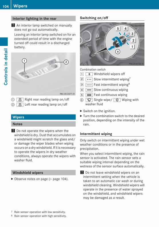
Interior lighting in the rear! An interior lamp switched on manually
does not go out automatically.Leaving an interior lamp switched on for anextended period of time with the engineturned off could result in a dischargedbattery.
: p Right rear reading lamp on/off; p Left rear reading lamp on/off
Wipers
Notes! Do not operate the wipers when the
windshield is dry. Dust that accumulates ona windshield might scratch the glass and/or damage the wiper blades when wipingoccurs on a dry windshield. If it is necessaryto operate the wipers in dry weatherconditions, always operate the wipers withwasher fluid.
Windshield wipersX Observe notes on page (Y page 104).
Switching on/off
Combination switch1 $ Windshield wipers off2Ä Slow intermittent wiping7
3Å Fast intermittent wiping8
4 ° Slow continuous wiping5 ¯ Fast continuous wipingB í Single wipe/ î Wiping with
washer fluid
X Switch on the ignition.X Turn the combination switch to the desired
position, depending on the intensity of therain.
Intermittent wiping Only switch on intermittent wiping under wetweather conditions or in the presence ofprecipitation.When you select intermittent wiping, the rainsensor is activated. The rain sensor sets asuitable wiping interval depending on thewetness of the sensor surface automatically.
! Do not leave windshield wipers on anintermittent setting when the vehicle istaken to an automatic car wash or duringwindshield cleaning. Windshield wipers willoperate in the presence of water sprayedon the windshield, and windshield wipersmay be damaged as a result.
7 Rain sensor operation with low sensitivity.8 Rain sensor operation with high sensitivity.
104 WipersCo
ntro
ls in
det
ail
212_AKB; 2; 41, en-USd2ureepe, Version: 2.11.8.1
2009-07-17T09:14:21+02:00 - Seite 104

! If you have set intermittent wiping, dirt onthe surface of the rain sensor or opticaleffects may cause the windshield wipers towipe in an undesired fashion. This couldthen damage the windshield wiper bladesor scratch the windshield. You shouldtherefore switch off the windshield wiperswhen weather conditions are dry.
X Turn the combination switch to positionÄ or Å.After the initial wipe, pauses betweenwipes are controlled by the rain sensorautomatically.
Intermittent wiping is interrupted when thevehicle is at a standstill and a front door isopened. This protects persons getting into orout of the vehicle from being sprayed.Intermittent wiping will be continued when alldoors are closed andRthe automatic transmission is in drive
position D or reverse gear RorRthe wiper setting is changed using the
combination switch
Single wipeX Press the combination switch briefly in
direction of arrow B to the resistancepoint.The windshield wipers wipe one timewithout washer fluid.
Wiping with washer fluidX Press the combination switch in direction
of arrow B past the resistance point.The windshield wipers operate with washerfluid.
i To prevent smears on the windshield ornoisy/chattering wiper blades, wipe withwasher fluid every now and then even whenit is raining.
For information on filling up the washerreservoir, see “Washer system and headlampcleaning system” (Y page 227).For information on cleaning the headlampswith washer fluid, see “Headlamp cleaningsystem” (Y page 102).
Problems with wipers! If anything blocks the windshield wipers
(leaves, snow, etc.), switch them offimmediately.For safety reasons, do the following beforeattempting to remove any blockage:RStop the vehicle in a safe location.RRemove the SmartKey from the starter
switch.orRTurn off the engine by pressing the
KEYLESS-GO start/stop button andopen the driver’s door (with the driver’sdoor open, starter switch is in position0, same as with SmartKey removed fromstarter switch).REngage the parking brake.RRemove blockage.RTurn the windshield wipers on again.If the windshield wipers fail to function atall with the combination switch in positionÄ or Å,Rset the combination switch to the next
higher wiper speedRhave the windshield wipers checked at
the nearest authorized Mercedes-BenzCenter
Power windows
Opening and closingThe door windows are opened and closedelectrically. The switches for all door windowsare located on the driver’s door control panel.
Power windows 105
Cont
rols
in d
etai
l
212_AKB; 2; 41, en-USd2ureepe, Version: 2.11.8.1
2009-07-17T09:14:21+02:00 - Seite 105
Z
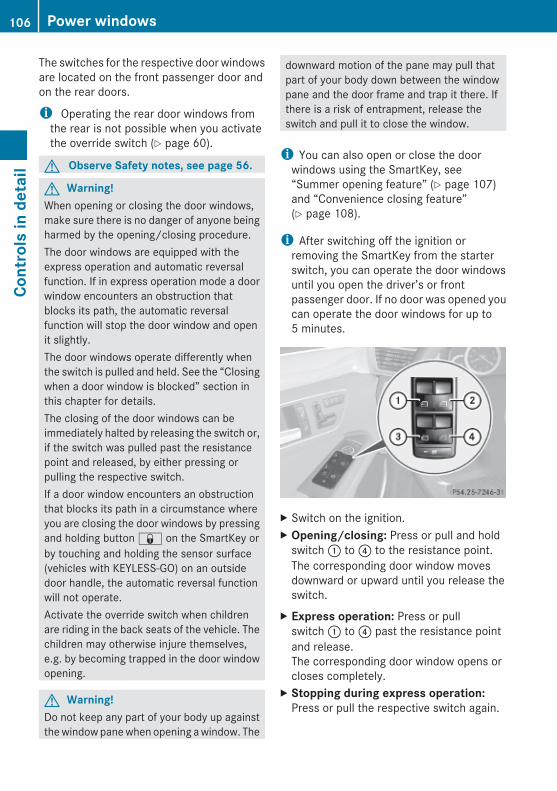
The switches for the respective door windowsare located on the front passenger door andon the rear doors.
i Operating the rear door windows fromthe rear is not possible when you activatethe override switch (Y page 60).
G Observe Safety notes, see page 56.
G Warning!When opening or closing the door windows,make sure there is no danger of anyone beingharmed by the opening/closing procedure.The door windows are equipped with theexpress operation and automatic reversalfunction. If in express operation mode a doorwindow encounters an obstruction thatblocks its path, the automatic reversalfunction will stop the door window and openit slightly.The door windows operate differently whenthe switch is pulled and held. See the “Closingwhen a door window is blocked” section inthis chapter for details.The closing of the door windows can beimmediately halted by releasing the switch or,if the switch was pulled past the resistancepoint and released, by either pressing orpulling the respective switch.If a door window encounters an obstructionthat blocks its path in a circumstance whereyou are closing the door windows by pressingand holding button & on the SmartKey orby touching and holding the sensor surface(vehicles with KEYLESS-GO) on an outsidedoor handle, the automatic reversal functionwill not operate.Activate the override switch when childrenare riding in the back seats of the vehicle. Thechildren may otherwise injure themselves,e.g. by becoming trapped in the door windowopening.
G Warning!Do not keep any part of your body up againstthe window pane when opening a window. The
downward motion of the pane may pull thatpart of your body down between the windowpane and the door frame and trap it there. Ifthere is a risk of entrapment, release theswitch and pull it to close the window.
i You can also open or close the doorwindows using the SmartKey, see“Summer opening feature” (Y page 107)and “Convenience closing feature”(Y page 108).
i After switching off the ignition orremoving the SmartKey from the starterswitch, you can operate the door windowsuntil you open the driver’s or frontpassenger door. If no door was opened youcan operate the door windows for up to5 minutes.
X Switch on the ignition.X Opening/closing: Press or pull and hold
switch : to ? to the resistance point.The corresponding door window movesdownward or upward until you release theswitch.
X Express operation: Press or pullswitch : to ? past the resistance pointand release.The corresponding door window opens orcloses completely.
X Stopping during express operation:Press or pull the respective switch again.
106 Power windowsCo
ntro
ls in
det
ail
212_AKB; 2; 41, en-USd2ureepe, Version: 2.11.8.1
2009-07-17T09:14:21+02:00 - Seite 106

Closing when a door window is blocked
G Warning!Make sure that nobody can become trappedand be seriously or even fatally injured whenclosing a door window with greater force orwithout automatic reversal function.
If the upward movement of a door window isblocked during the closing procedure, thedoor window will stop and open slightly.X Immediately after the door window has
stopped because it was blocked, pull andhold the respective switch upward until thedoor window is fully closed.The door window closes with greater force.
If the door window is blocked again and opensslightly:X Immediately after the door window was
blocked, pull and hold the respectiveswitch upward until the door window is fullyclosed.The door window closes without automaticreversal function.
G Warning!Pulling and holding the switch to close thedoor window immediately after it had beenblocked two times will cause the door windowto close without any reversal function for aslong as you hold the switch.
Synchronizing door windowsThe door windows must be synchronized ifthey cannot be fully closed (expressoperation).Each door window must be synchronizedseparately.X Close all doors.X Switch on the ignition.X Pull and hold switch :, ;, = or ?
(Y page 106) until the respective doorwindow is closed.The door window opens again slightly.
X Pull and hold the respective switch oncemore immediately until the door window isclosed completely.
X Hold the respective switch forapproximately 1 second.The door window is synchronized.
Summer opening featureWhen the weather is warm, you can ventilatethe vehicle before driving off bysimultaneouslyRopening the door windowsRopening the tilt/sliding sunroofRopening the panorama roof with power tilt/
sliding panel and roller sunblindsRswitching on the seat ventilation for the
driver’s seatThe summer opening feature can only beactivated via the remote control of theSmartKey. The SmartKey must be in closeproximity to the driver’s outside door handle.X Aim the transmitter eye of the SmartKey at
the driver’s outside door handle.X Press button % on the SmartKey to
unlock the vehicle.Keep button % pressed until the doorwindows and the tilt/sliding panel of thepanorama roof or the tilt/sliding sunroofhave reached the desired position.Vehicles with panorama roof with power tilt/sliding panel: When the rollersunblinds of the panorama roof with powertilt/sliding panel are closed, the rollersunblinds will open first.
X Press button % once more until the tilt/sliding panel of the panorama roof hasreached the desired position.
X Release button % on the SmartKey tointerrupt the opening procedure.
Power windows 107
Cont
rols
in d
etai
l
212_AKB; 2; 41, en-USd2ureepe, Version: 2.11.8.1
2009-07-17T09:14:21+02:00 - Seite 107
Z

Convenience closing featureWhen locking the vehicle, you cansimultaneously closeRthe door windowsRthe tilt/sliding sunroofRthe panorama roof with power tilt/sliding
panelAfterward, you can extend the rollersunblinds of the panorama roof with powertilt/sliding panel.
G Warning!When closing the door windows and the tilt/sliding sunroof or panorama roof with powertilt/sliding panel, make sure there is nodanger of anyone being harmed by the closingprocedure.If potential danger exists, proceed as follows:RRelease button & to stop the closing
procedure. To open, press and hold button%. To continue the closing procedureafter making sure that there is no danger ofanyone being harmed by the closingprocedure, press and hold button &.
Vehicles with KEYLESS-GO:RRelease the sensor surface on the outside
door handle to stop the closing procedure.RImmediately pull on the same outside door
handle and hold firmly. The door windowsand the tilt/sliding sunroof or panoramaroof with power tilt/sliding panel will openfor as long as the door handle is held butthe door not opened.
With SmartKeyThe SmartKey must be in close proximity tothe driver’s outside door handle.X Aim transmitter eye of the SmartKey at the
driver’s outside door handle.X Press and hold button & on the
SmartKey until the door windows and thetilt/sliding sunroof or panorama roof with
power tilt/sliding panel are closedcompletely.
X Release button & on the SmartKey tointerrupt the closing procedure.
X Vehicles with panorama roof with power tilt/sliding panel: Press and holdbutton & on the SmartKey once more.The roller sunblinds extend.
X Release button & on the SmartKey tointerrupt the extending procedure.
With KEYLESS-GO
The SmartKey with KEYLESS-GO must belocated outside the vehicle withinapproximately 3 ft (1 m) of a door.X Close all doors.X Touch and hold sensor surface : on an
outside door handle (Y page 79) until thedoor windows and the tilt/sliding sunroofor panorama roof with power tilt/slidingpanel are closed completely.
i Make sure you are only touching sensorsurface :.
X Release sensor surface : on the outsidedoor handle to interrupt the closingprocedure.
X Vehicles with panorama roof with power tilt/sliding panel: Touch and hold
108 Power windowsCo
ntro
ls in
det
ail
212_AKB; 2; 41, en-USd2ureepe, Version: 2.11.8.1
2009-07-17T09:14:21+02:00 - Seite 108
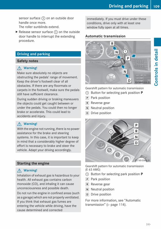
sensor surface : on an outside doorhandle once more.The roller sunblinds extend.
X Release sensor surface : on the outsidedoor handle to interrupt the extendingprocedure.
Driving and parking
Safety notes
G Warning!Make sure absolutely no objects areobstructing the pedals’ range of movement.Keep the driver’s footwell clear of allobstacles. If there are any floormats orcarpets in the footwell, make sure the pedalsstill have sufficient clearance.During sudden driving or braking maneuversthe objects could get caught between orunder the pedals. You could then no longerbrake or accelerate. This could lead toaccidents and injury.
G Warning!With the engine not running, there is no powerassistance for the brake and steeringsystems. In this case, it is important to keepin mind that a considerably higher degree ofeffort is necessary to brake and steer thevehicle. Adapt your driving accordingly.
Starting the engine
G Warning!Inhalation of exhaust gas is hazardous to yourhealth. All exhaust gas contains carbonmonoxide (CO), and inhaling it can causeunconsciousness and possible death.Do not run the engine in confined areas (suchas a garage) which are not properly ventilated.If you think that exhaust gas fumes areentering the vehicle while driving, have thecause determined and corrected
immediately. If you must drive under theseconditions, drive only with at least onewindow fully open at all times.
Automatic transmission
Gearshift pattern for automatic transmission: Button for selecting park position Pj Park positionk Reverse geari Neutral positionh Drive position
Gearshift pattern for automatic transmission(E 63 AMG): Button for selecting park position Pj Park positionk Reverse geari Neutral positionh Drive position
For more information, see “Automatictransmission” (Y page 114).
Driving and parking 109
Cont
rols
in d
etai
l
212_AKB; 2; 41, en-USd2ureepe, Version: 2.11.8.1
2009-07-17T09:14:21+02:00 - Seite 109
Z

X Make sure the automatic transmission is inpark position P.The transmission position indicator in themultifunction display should be on P(Y page 118).
With SmartKey X Do not depress the accelerator pedal.X Gasoline engine: Turn the SmartKey in the
starter switch to position 3 (Y page 85) andrelease it.The engine starts automatically.
X Diesel engine: Turn the SmartKey in thestarter switch to position 2 (Y page 85).Preglow indicator lamp % in theinstrument cluster comes on.
X As soon as preglow indicator lamp %goes out, turn the SmartKey in the starterswitch to position 3 and release it.The engine starts automatically.
i If the engine is at operating temperature,preglow indicator lamp % may not stayon and you can start the engine withoutpreglowing.
With KEYLESS-GO
G Warning!As long as the SmartKey is in your vehicle, thevehicle can be started. Therefore, never leavechildren unattended in the vehicle, as theycould otherwise accidentally start the engine.When leaving the vehicle, always take theSmartKey with you and lock the vehicle. Donot leave children unattended in the vehicle,or with access to an unlocked vehicle. Achild’s unsupervised access to a vehicle couldresult in an accident and/or serious personalinjury.
You can start your vehicle without theSmartKey in the starter switch using theKEYLESS-GO start/stop button.The SmartKey must be located in the vehicle.
KEYLESS-GO start/stop button: USA only; Canada only
X Make sure the KEYLESS-GO start/stopbutton is inserted in the starter switch(Y page 86).
i To start the engine with the SmartKeyinstead of the KEYLESS-GO function,remove the KEYLESS-GO start/stop buttonfrom the starter switch. Proceed asdescribed in “With SmartKey”(Y page 110).
X Depress the brake pedal during the startingprocedure.
X Do not depress the accelerator pedal.X Gasoline engine: Press the KEYLESS-GO
start/stop button once.The engine starts automatically.
X Diesel engine: Press the KEYLESS-GOstart/stop button once.The engine preglows and startsautomatically.
i If the engine is at operating temperature,the time the engine needs to preglow isreduced.
Starting difficulties ! Remember that extended starting
attempts can drain the battery.
110 Driving and parkingCo
ntro
ls in
det
ail
212_AKB; 2; 41, en-USd2ureepe, Version: 2.11.8.1
2009-07-17T09:14:21+02:00 - Seite 110

The engine does not start. You can hear the starter.There could be a malfunction in the engineelectronics or in the fuel supply system.Carry out the following steps:X If you are starting the engine with the
SmartKey: Turn the SmartKey in the starterswitch to position 0 and repeat the startingprocedure.
X If you are starting the engine with KEYLESS-GO: Close any doors that may be open toallow for better detection of the SmartKey.
orX Remove the KEYLESS-GO start/stop
button from the starter switch.X Start the engine with the SmartKey as radio
signals from another source may beinterfering with the KEYLESS-GO function.
X Repeat the starting procedure.
If the engine does not start after severalstarting attempts:X Contact an authorized Mercedes-Benz
Center or call Roadside Assistance.
The engine does not start. You cannot hear the starter.The battery may not be charged sufficiently.X Get a jump start (Y page 338).
If the engine will not start despite a jumpstart:X Contact an authorized Mercedes-Benz
Center or call Roadside Assistance.The starter has been exposed to excessivetemperatures.X Let the starter cool for about 2 minutes.X Repeat the starting procedure.
If the engine does not start after severalstarting attempts:X Contact an authorized Mercedes-Benz
Center or call Roadside Assistance.
Driving off
G Warning!On slippery road surfaces, never downshift inorder to obtain braking action. This couldresult in drive wheel slip and reduced vehiclecontrol. Your vehicle’s ABS will not preventthis type of loss of control.
! Do not run a cold engine at high enginespeeds. Running a cold engine at highengine speeds may shorten the service lifeof the engine. This is not covered by theMercedes-Benz Limited Warranty.E 63 AMG: At engine temperatures below68‡ (20†), the engine’s maximum speedis restricted in order to protect it fromdamage. Avoid driving your vehicle at fullspeed when the engine is cold to preventpremature engine wear and/or diminishedcomfort.
! If an acoustic warning sounds and themessage Release Parking Brakeappears in the multifunction display whendriving off, you have forgotten to releasethe parking brake.Release the parking brake.
! Avoid spinning of a drive wheel. This maycause serious damage to the drivetrainwhich is not covered by the Mercedes-BenzLimited Warranty.
! Simultaneously depressing theaccelerator pedal and applying the brakesreduces engine performance and causespremature brake and drivetrain wear whichis not covered by the Mercedes-BenzLimited Warranty.
i Once the vehicle is in motion, theautomatic central locking function engagesand the locking knobs in the doors movedown.
Driving and parking 111
Cont
rols
in d
etai
l
212_AKB; 2; 41, en-USd2ureepe, Version: 2.11.8.1
2009-07-17T09:14:21+02:00 - Seite 111
Z
The automatic central locking function canbe switched off (Y page 144).
Automatic transmission
G Warning!It is dangerous to shift the automatictransmission out of park position P or neutralposition N if the engine speed is higher thanidle speed. If your foot is not firmly on thebrake pedal, the vehicle could acceleratequickly forward or in reverse. You could losecontrol of the vehicle and hit someone orsomething. Only shift into gear when theengine is idling normally and when your rightfoot is firmly on the brake pedal.
! Only shift the automatic transmission intoreverse gear R or park position P when thevehicle is stopped. Otherwise theautomatic transmission could be damaged.
X Depress the brake pedal.The gear selector lever can now be used.
X Shift the automatic transmission into driveposition D or reverse gear R.
i Shifting the automatic transmission out ofpark position P is only possible with thebrake pedal depressed.Without the brake pedal depressed, thegear selector lever can be moved up ordown. However, the parking pawl remainsengaged, not allowing shifting to occur.
X Wait for the gear selection process tocomplete before setting the vehicle inmotion.
X If engaged, release the parking brake.X Release the brake pedal.X Carefully depress the accelerator pedal.After a cold start, the automatic transmissionshifts at a higher engine speed. This allowsthe catalytic converter (gasoline engine) orthe oxidation catalyst (diesel engine) to reachits operating temperature earlier.
For more information on driving, see “Drivinginstructions” (Y page 254).
Problems while driving
The engine runs erratically and misfiresRGasoline engine: An ignition cable may be
damaged.RThe engine electronics may not be
operating properly.RGasoline engine: Unburned gasoline may
have entered the catalytic converter anddamaged it.
X Give very little gas.X Have the problem checked at an authorized
Mercedes-Benz Center as soon as possible.
The coolant temperature is above 248‡ (120†)The coolant is too hot and is no longer coolingthe engine.X Stop the vehicle in a safe location as soon
as possible.X Turn off the engine immediately.X Allow the engine and coolant to cool off.X Check the coolant level and add coolant if
necessary (Y page 226).
In case of accident If the vehicle is leaking fuel:X Do not start the engine under any
circumstances.X Exit the vehicle at a safe distance from the
roadway.X Notify local fire and/or police authorities.
If the extent of the damage cannot bedetermined:X Contact an authorized Mercedes-Benz
Center or call Roadside Assistance.
112 Driving and parkingCo
ntro
ls in
det
ail
212_AKB; 2; 41, en-USd2ureepe, Version: 2.11.8.1
2009-07-17T09:14:21+02:00 - Seite 112

If no damage on major assemblies, fuelsystem, and engine mount can bedetermined:X Start the engine in the usual manner.
Parking
G Warning!Do not park this vehicle in areas wherecombustible materials such as grass, hay orleaves can come into contact with the hotexhaust system. These materials could beignited and cause a vehicle fire.Vehicle movement may result in seriouspersonal injury or damage to the vehicle orvehicle drivetrain. Therefore, always do thefollowing before turning off the engine andleaving the vehicle:RKeep right foot on the brake pedal.REngage the parking brake.RShift the automatic transmission into park
position P.RSlowly release the brake pedal.RWhen parked on an incline, always turn the
front wheels towards the road curb.RTurn the SmartKey in the starter switch to
position 0 and remove the SmartKey fromthe starter switch, or press the KEYLESS-GO start/stop button.RTake the SmartKey with you and lock the
vehicle when leaving.
Parking brake
G Warning!Engaging the parking brake while the vehicleis in motion can cause the rear wheels to lockup. You could lose control of the vehicle andcause an accident. In addition, the vehicle’sbrake lights do not light up when the parkingbrake is engaged.
G Warning!When leaving the vehicle, always remove theSmartKey from the starter switch, take it withyou, and lock the vehicle. Do not leavechildren unattended in the vehicle, or withaccess to an unlocked vehicle. Children couldrelease the parking brake and/or shift theautomatic transmission out of park positionP, either of which could result in an accidentand/or serious personal injury.
X Releasing: Pull on release handle :.When the ignition is switched on or theengine is running, the brake warning lamp$ (USA only) or J (Canada only) inthe instrument cluster goes out.
X Engaging: Step on parking brakepedal ; firmly.When the engine is running, the brakewarning lamp $ (USA only) or J(Canada only) in the instrument clustercomes on.
Turning off the engine
G Warning!Do not turn off the engine before the vehiclehas come to a complete stop. With the enginenot running, there is no power assistance forthe brake and steering systems. In this case,it is important to keep in mind that aconsiderably higher degree of effort isnecessary to brake and steer the vehicle.
Driving and parking 113
Cont
rols
in d
etai
l
212_AKB; 2; 41, en-USd2ureepe, Version: 2.11.8.1
2009-07-17T09:14:21+02:00 - Seite 113
Z

X Shift the automatic transmission into parkposition P (Y page 116).
X Engage the parking brake.
i Always engage the parking brake inaddition to shifting the automatictransmission into park position P.
i Observe instructions if you want theautomatic transmission to remain inneutral position N, see “Remaining inneutral position N” (Y page 115).
With SmartKey X Turn the SmartKey in the starter switch to
position 0.X Remove the SmartKey from the starter
switch.When you turn off the engine using theSmartKey, and remove the SmartKey fromthe starter switch or open a front door, theautomatic transmission will shift into parkposition P automatically.
G Warning!Keep in mind that turning off the engine aloneonly will shift the automatic transmission intoneutral position N automatically.Always shift the automatic transmission intopark position P before turning off the engine.Otherwise the vehicle could roll away whichcould result in an accident and/or seriouspersonal injury.
With KEYLESS-GOX Press the KEYLESS-GO start/stop button.
With the driver’s door closed, the starterswitch is now in position 1. With the driver’sdoor opened, the starter switch is set toposition 0, same as the SmartKey removedfrom the starter switch (Y page 85).
When you turn off the engine using theKEYLESS-GO start/stop button and open afront door, the automatic transmission willshift into park position P automatically.
G Warning!Keep in mind that turning off the engine aloneonly will shift the automatic transmission intoneutral position N automatically.Always shift the automatic transmission intopark position P before turning off the engine.Otherwise the vehicle could roll away whichcould result in an accident and/or seriouspersonal injury.
i In an emergency you can turn off theengine while driving by pressing andholding the KEYLESS-GO start/stop buttonfor approximately 3 seconds.
If you have started the engine with theKEYLESS-GO start/stop button and cannotturn it off as described above:X Remove the KEYLESS-GO start/stop
button from the starter switch.X Insert the SmartKey into the starter switch.
The engine turns off. The starter switch isin position 0 (Y page 85).
Automatic transmission
IntroductionFor information on driving with an automatictransmission, see “Driving and parking”(Y page 109).
G Warning!Make sure absolutely no objects areobstructing the pedals’ range of movement.Keep the driver’s footwell clear of allobstacles. If there are any floormats orcarpets in the footwell, make sure the pedalsstill have sufficient clearance.During sudden driving or braking maneuversthe objects could get caught between orunder the pedals. You could then no longerbrake or accelerate. This could lead toaccidents and injury.
114 Automatic transmissionCo
ntro
ls in
det
ail
212_AKB; 2; 41, en-USd2ureepe, Version: 2.11.8.1
2009-07-17T09:14:21+02:00 - Seite 114
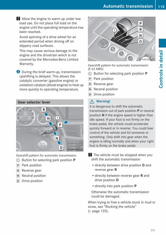
! Allow the engine to warm up under lowload use. Do not place full load on theengine until the operating temperature hasbeen reached.Avoid spinning of a drive wheel for anextended period when driving off onslippery road surfaces.This may cause serious damage to theengine and the drivetrain which is notcovered by the Mercedes-Benz LimitedWarranty.
i During the brief warm-up, transmissionupshifting is delayed. This allows thecatalytic converter (gasoline engine) oroxidation catalyst (diesel engine) to heat upmore quickly to operating temperature.
Gear selector lever
Gearshift pattern for automatic transmission: Button for selecting park position Pj Park positionk Reverse geari Neutral positionh Drive position
Gearshift pattern for automatic transmission(E 63 AMG): Button for selecting park position Pj Park positionk Reverse geari Neutral positionh Drive position
G Warning!It is dangerous to shift the automatictransmission out of park position P or neutralposition N if the engine speed is higher thanidle speed. If your foot is not firmly on thebrake pedal, the vehicle could acceleratequickly forward or in reverse. You could losecontrol of the vehicle and hit someone orsomething. Only shift into gear when theengine is idling normally and when your rightfoot is firmly on the brake pedal.
! The vehicle must be stopped when youshift the automatic transmissionRdirectly between drive position D and
reverse gear RRdirectly between reverse gear R and
drive position DRdirectly into park position POtherwise the automatic transmissioncould be damaged.
When trying to free a vehicle stuck in mud orsnow, see “Rocking the vehicle”(Y page 120).
Automatic transmission 115
Cont
rols
in d
etai
l
212_AKB; 2; 41, en-USd2ureepe, Version: 2.11.8.1
2009-07-17T09:14:21+02:00 - Seite 115
Z
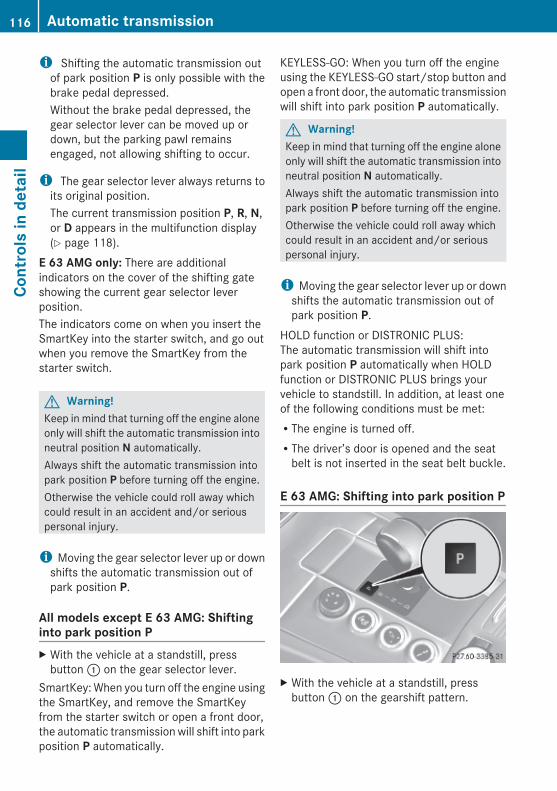
i Shifting the automatic transmission outof park position P is only possible with thebrake pedal depressed.Without the brake pedal depressed, thegear selector lever can be moved up ordown, but the parking pawl remainsengaged, not allowing shifting to occur.
i The gear selector lever always returns toits original position.The current transmission position P, R, N,or D appears in the multifunction display(Y page 118).
E 63 AMG only: There are additionalindicators on the cover of the shifting gateshowing the current gear selector leverposition.The indicators come on when you insert theSmartKey into the starter switch, and go outwhen you remove the SmartKey from thestarter switch.
G Warning!Keep in mind that turning off the engine aloneonly will shift the automatic transmission intoneutral position N automatically.Always shift the automatic transmission intopark position P before turning off the engine.Otherwise the vehicle could roll away whichcould result in an accident and/or seriouspersonal injury.
i Moving the gear selector lever up or downshifts the automatic transmission out ofpark position P.
All models except E 63 AMG: Shifting into park position PX With the vehicle at a standstill, press
button : on the gear selector lever.SmartKey: When you turn off the engine usingthe SmartKey, and remove the SmartKeyfrom the starter switch or open a front door,the automatic transmission will shift into parkposition P automatically.
KEYLESS-GO: When you turn off the engineusing the KEYLESS-GO start/stop button andopen a front door, the automatic transmissionwill shift into park position P automatically.
G Warning!Keep in mind that turning off the engine aloneonly will shift the automatic transmission intoneutral position N automatically.Always shift the automatic transmission intopark position P before turning off the engine.Otherwise the vehicle could roll away whichcould result in an accident and/or seriouspersonal injury.
i Moving the gear selector lever up or downshifts the automatic transmission out ofpark position P.
HOLD function or DISTRONIC PLUS:The automatic transmission will shift intopark position P automatically when HOLDfunction or DISTRONIC PLUS brings yourvehicle to standstill. In addition, at least oneof the following conditions must be met:RThe engine is turned off.RThe driver’s door is opened and the seat
belt is not inserted in the seat belt buckle.
E 63 AMG: Shifting into park position P
X With the vehicle at a standstill, pressbutton : on the gearshift pattern.
116 Automatic transmissionCo
ntro
ls in
det
ail
212_AKB; 2; 41, en-USd2ureepe, Version: 2.11.8.1
2009-07-17T09:14:21+02:00 - Seite 116

G Warning!Keep in mind that turning off the engine aloneonly will shift the automatic transmission intoneutral position N automatically.Always shift the automatic transmission intopark position P before turning off the engine.Otherwise the vehicle could roll away whichcould result in an accident and/or seriouspersonal injury.
Shifting into neutral position NX With the vehicle at a standstill, depress the
brake pedal.X Move the gear selector lever up or down to
the resistance point to select neutralposition N.
When you turn off the engine, the automatictransmission will shift into neutral positionN automatically.SmartKey: Removing the SmartKey from thestarter switch or opening a front door afterturning off the engine will shift the automatictransmission into park position Pautomatically.KEYLESS-GO: Opening a front door afterturning off the engine will shift the automatictransmission into park position Pautomatically.
Remaining in neutral position NIf you want the automatic transmission toremain in neutral position N, e.g. when takingthe vehicle through an automatic conveyor-type car wash, observe the followinginstructions.
G Warning!When leaving the SmartKey in the starterswitch, do not leave children unattended inthe vehicle. It is possible for children to switchon the ignition which could result inunsupervised use of vehicle equipment.Unsupervised use of vehicle equipment couldresult in an accident and/or serious personalinjury.
With SmartKey:X Make sure the ignition is switched on.X With the vehicle at a standstill, depress the
brake pedal and keep it pressed.X Shift the automatic transmission into
neutral position N.X Release the brake pedal.X If engaged, release the parking brake.X Switch off the ignition and leave the
SmartKey in the starter switch.
With KEYLESS-GO:X Make sure the ignition is switched on.X With the vehicle at a standstill, depress the
brake pedal and keep it pressed.X Shift the automatic transmission into park
position P.X Release the brake pedal.X Remove the KEYLESS-GO start/stop
button from the starter switch.X Insert the SmartKey into the starter switch.X Switch on the ignition.X Depress the brake pedal and keep it
pressed.X Shift the automatic transmission into
neutral position N.X Release the brake pedal.X If engaged, release the parking brake.X Switch off the ignition and leave the
SmartKey in the starter switch.
Shifting into reverse gear RX With the vehicle at a standstill, depress the
brake pedal.X Move the gear selector lever up past the
resistance point.
Shifting into drive position DX With the vehicle at a standstill, depress the
brake pedal.X Move the gear selector lever down past the
resistance point.
Automatic transmission 117
Cont
rols
in d
etai
l
212_AKB; 2; 41, en-USd2ureepe, Version: 2.11.8.1
2009-07-17T09:14:21+02:00 - Seite 117
Z
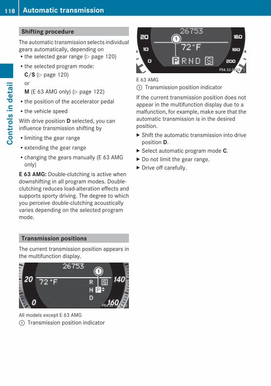
Shifting procedureThe automatic transmission selects individualgears automatically, depending onRthe selected gear range (Y page 120)Rthe selected program mode:
C/S (Y page 120)orM (E 63 AMG only) (Y page 122)Rthe position of the accelerator pedalRthe vehicle speedWith drive position D selected, you caninfluence transmission shifting byRlimiting the gear rangeRextending the gear rangeRchanging the gears manually (E 63 AMG
only)E 63 AMG: Double-clutching is active whendownshifting in all program modes. Double-clutching reduces load-alteration effects andsupports sporty driving. The degree to whichyou perceive double-clutching acousticallyvaries depending on the selected programmode.
Transmission positionsThe current transmission position appears inthe multifunction display.
All models except E 63 AMG: Transmission position indicator
E 63 AMG: Transmission position indicator
If the current transmission position does notappear in the multifunction display due to amalfunction, for example, make sure that theautomatic transmission is in the desiredposition.X Shift the automatic transmission into drive
position D.X Select automatic program mode C.X Do not limit the gear range.X Drive off carefully.
118 Automatic transmissionCo
ntro
ls in
det
ail
212_AKB; 2; 41, en-USd2ureepe, Version: 2.11.8.1
2009-07-17T09:14:21+02:00 - Seite 118

Effect
B Park positionShift the automatic transmissioninto park position P only when thevehicle is stopped. The parkposition is not intended to serve asa brake when the vehicle is parked.Rather, the driver should alwaysengage the parking brake inaddition to shifting the automatictransmission into park position P tosecure the vehicle.The SmartKey can only be removedfrom the starter switch with thegear selector lever in park positionP. With the SmartKey removed fromthe starter switch, the gear selectorlever is locked in park position P.If the vehicle’s electrical system ismalfunctioning, the automatictransmission could remain lockedin park position P.X Have the vehicle’s electrical
system checked at an authorizedMercedes-Benz Center as soonas possible.
C Reverse gearShift the automatic transmissioninto reverse gear R only when thevehicle is stopped.
Effect
A Neutral positionNo power is transmitted from theengine to the drive axle. When thebrakes are released, the vehicle canbe moved freely (pushed or towed).To avoid damage to thetransmission, never shift theautomatic transmission into neutralposition N while driving.Exception: If the ESC is switched offor malfunctioning, shift theautomatic transmission into neutralposition N if the vehicle is in dangerof skidding.
! Coasting the vehicle, or drivingfor any other reason with theautomatic transmission inneutral position N can result intransmission damage that is notcovered by the Mercedes-BenzLimited Warranty.
7 Drive positionThe automatic transmission shiftsautomatically. All forward gears areavailable.
Driving tips
Kickdown Use the kickdown when you want maximumacceleration.X U.S. vehicles except AMG vehicles:
Fully depress the accelerator pedal.Depending on the engine speed theautomatic transmission shifts into a lowergear.
X Canada vehicles and AMG vehicles:Depress the accelerator pedal past thepoint of resistance.Depending on the engine speed theautomatic transmission shifts into a lowergear.
Automatic transmission 119
Cont
rols
in d
etai
l
212_AKB; 2; 41, en-USd2ureepe, Version: 2.11.8.1
2009-07-17T09:14:21+02:00 - Seite 119
Z

Rocking the vehicleRocking the vehicle by shifting the automatictransmission directly between drive positionD and reverse gear R can help free a vehiclestuck in mud or snow. The engine controlsystem of this vehicle electronically limitsdirectly shifting the automatic transmissionbetween drive position D and reverse gear Rto very low speeds, i.e. approximately 5 mph(9 km/h). To shift the automatic transmissiondirectly between drive position D and reversegear R, move the gear selector lever up ordown past the resistance point.
Working on the vehicle
G Warning!When working on the vehicle, engage theparking brake and shift the automatictransmission into park position P. Otherwisethe vehicle could roll away which could resultin an accident and/or serious personal injury.
Gear rangesWith the automatic transmission in driveposition D, you can limit or extend the gearrange, see “One-touch gearshifting”(Y page 121).The current gear range appears in themultifunction display.
All models except E 63 AMG: Gear range indicator
The current gear range appears in themultifunction display.
E 63 AMG: Gear range indicator
Effect
= With this selection you can use thebraking effect of the engine.
5 Allows the use of the engine’sbraking effect when drivingRon steep downgradesRin mountainous regionsRunder extreme operating
conditions
4 For maximum use of the engine’sbraking effect on very steep orlengthy downgrades.
Automatic shift program
Program mode selector switch on all modelsexcept E 63 AMG
C Comfort For comfort driving
S Sport For sporty driving
120 Automatic transmissionCo
ntro
ls in
det
ail
212_AKB; 2; 41, en-USd2ureepe, Version: 2.11.8.1
2009-07-17T09:14:21+02:00 - Seite 120

Program mode selector dial on E 63 AMG
C Comfort For standard driving
S Sport For sporty driving
S+ Sport Plus For sporty driving withshorter shift times
M Manual For manual gearshifting(Y page 122)
RS RACE START For optimumacceleration from astanding start
i Program mode RS cannot be selectedwhile driving. For more information, see“RACE START (E 63 AMG)” (Y page 159).
The current program mode appears in themultifunction display.
E 63 AMG: Program mode indicator
i E 63 AMG: In addition, the currentlyselected program mode is indicated in redon the program mode selector dial.
You should only change the program modewhen the automatic transmission is in parkposition P.
Automatic program mode S will not be stored.When the engine is turned off with theautomatic program mode S selected, theautomatic transmission will go to theautomatic program mode C when the engineis restarted.E 63 AMG: Automatic program mode S+ willnot be stored. When the engine is turned offwith automatic program mode S+ selected,the automatic transmission will go toautomatic program mode C when the engineis restarted.X All models except E 63 AMG: Press the
program mode selector switch repeatedlyuntil the letter of the desired program modeappears in the right multifunction display.
X E 63 AMG: Turn the program modeselector dial until the letter of the desiredprogram mode appears in the rightmultifunction display.
Selecting program mode C means:RThe vehicle starts out more gentle, both
forward and reverse, except when drivingoff with full throttle.RTraction and driving stability are improved
on icy roads.RUpshifts occur earlier even when you give
more gas. The engine then operates atlower revolutions and the wheels are lesslikely to spin.
Selecting program mode S means thatupshifts occur later.
One-touch gearshiftingWith the automatic transmission in driveposition D, you can limit or extend the gearrange using the steering wheel gearshiftcontrol.E 63 AMG: You only can limit or extend thegear range when driving in automaticprogram mode C, S,or S+. For information onusing the steering wheel gearshift control in
Automatic transmission 121
Cont
rols
in d
etai
l
212_AKB; 2; 41, en-USd2ureepe, Version: 2.11.8.1
2009-07-17T09:14:21+02:00 - Seite 121
Z
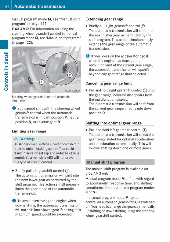
manual program mode M, see “Manual shiftprogram” (Y page 122).E 63 AMG: For information on using thesteering wheel gearshift control in manualprogram mode M, see “Manual shift program”(Y page 122).
Steering wheel gearshift control (exampleillustration)
i You cannot shift with the steering wheelgearshift control when the automatictransmission is in park position P, neutralposition N, or reverse gear R.
Limiting gear range
G Warning!On slippery road surfaces, never downshift inorder to obtain braking action. This couldresult in drive wheel slip and reduced vehiclecontrol. Your vehicle’s ABS will not preventthis type of loss of control.
X Briefly pull left gearshift control :.The automatic transmission will shift intothe next lower gear as permitted by theshift program. This action simultaneouslylimits the gear range of the automatictransmission.
i To avoid overrevving the engine whendownshifting, the automatic transmissionwill not shift into a lower gear if the engine’smaximum speed would be exceeded.
Extending gear rangeX Briefly pull right gearshift control ;.
The automatic transmission will shift intothe next higher gear as permitted by theshift program. This action simultaneouslyextends the gear range of the automatictransmission.
i If you press on the accelerator pedalwhen the engine has reached therevolution limit of the current gear range,the automatic transmission will upshiftbeyond any gear range limit selected.
Canceling gear range limitX Pull and hold right gearshift control ; until
the gear range indicator disappears fromthe multifunction display.The automatic transmission will shift fromthe current gear range directly into driveposition D.
Shifting into optimal gear range X Pull and hold left gearshift control :.
The automatic transmission will select thegear range suited for optimal accelerationand deceleration automatically. This willinvolve shifting down one or more gears.
Manual shift programThe manual shift program is available onE 63 AMG only.Manual program mode M differs with regardto spontaneity, response time, and shiftingsmoothness from automatic program modesS or S+.In manual program mode M, system-controlled automatic gearshifting is switchedoff. You need to change the gears by manuallyupshifting or downshifting using the steeringwheel gearshift control.
122 Automatic transmissionCo
ntro
ls in
det
ail
212_AKB; 2; 41, en-USd2ureepe, Version: 2.11.8.1
2009-07-17T09:14:21+02:00 - Seite 122

Program mode selector dial on E 63 AMG
C Comfort For standard driving
S Sport For sporty driving
S+ Sport Plus For sporty driving withshorter shift times
M Manual For manual gearshifting
RS RACE START For optimumacceleration from astanding start
i Program mode RS cannot be selectedwhile driving. For more information, see“RACE START (E 63 AMG)” (Y page 159).
The current program mode appears in themultifunction display (Y page 121).For information on automatic program mode(C or S), see “Automatic shift program”(Y page 120) and “One-touch gearshifting”(Y page 121).
Activating manual shift programX Turn the program mode selector dial untilM appears in the multifunction display.The automatic transmission switches tomanual program mode M. Automaticshifting is switched off. The gear range isnot limited.
You can change the gears manually with driveposition D selected. You can upshift ordownshift through the gears in succession.
i Manual program mode M will not bestored. When the engine is turned off withmanual program mode M selected, theautomatic transmission will go toautomatic program mode C when theengine is restarted.
Upshifting! In manual program mode M, the
automatic transmission will not upshift,even if the engine has reached itsoverrevving range. Shift up into the nextgear before the engine has reached itsoverrevving range. Make absolutely certainthat the engine speed does not reach thered marking on the tachometer. Otherwisethe engine could be damaged which is notcovered by the Mercedes-Benz LimitedWarranty.
X Briefly pull right gearshift control ;(Y page 122).The automatic transmission shifts into thenext higher gear.
Upshift indicator
In manual program mode M, upshiftindicator ; in the multifunction displayadvises you to upshift before the enginereaches the overspeed range. Thus you candrive at the maximum engine speed for eachgear without overrevving the engine.X Shift the automatic transmission from
current gear : into the next higher gear.The fuel supply will otherwise beinterrupted to prevent the engine fromoverrevving.
Automatic transmission 123
Cont
rols
in d
etai
l
212_AKB; 2; 41, en-USd2ureepe, Version: 2.11.8.1
2009-07-17T09:14:21+02:00 - Seite 123
Z

Downshifting
G Warning!On slippery road surfaces, never downshift inorder to obtain braking action. This couldresult in drive wheel slip and reduced vehiclecontrol. Your vehicle’s ABS will not preventthis type of loss of control.
X Briefly pull left gearshift control :(Y page 122).The automatic transmission shifts into thenext lower gear.
i When you brake or stop, the automatictransmission shifts down into a gear fromwhich you can easily accelerate or take off.
Kickdown Using the kickdown while driving in manualprogram mode M is not possible.
Deactivating manual shift programX Turn the program mode selector dial untilC or S appears in the multifunction display.
orX Restart the engine.
The automatic transmission will go toautomatic program mode C.
Manual program mode M is not stored.
Emergency operation (limp-home mode)
If vehicle acceleration becomes lessresponsive or sluggish or the automatictransmission no longer shifts, the automatictransmission is most likely operating in limp-home (emergency operation) mode. In thismode only second gear and reverse gear Rcan be selected.X Stop the vehicle in a safe location.X Shift the automatic transmission into park
position P.X Turn off the engine.
X Wait at least 10 seconds before restarting.X Restart the engine.X Shift the automatic transmission into drive
position D (for second gear) or reverse gearR.
X Have the automatic transmission checkedat an authorized Mercedes-Benz Center assoon as possible.
Transfer case
This section applies to vehicles equipped withall-wheel drive (4MATIC) only. Both the frontand rear axles are powered at all times whenthe vehicle is being operated.
! Only conduct operational or performancetests on a two-axle dynamometer. If suchtests are necessary, contact an authorizedMercedes-Benz Center. You couldotherwise seriously damage the brakesystem or the transfer case which is notcovered by the Mercedes-Benz LimitedWarranty.
! Because the ESC operates automatically,the engine and ignition must be shut off(SmartKey in starter switch position 0, or1, or KEYLESS-GO start/stop button inposition 0, or 1) whenRthe parking brake is being tested on a
brake test dynamometerRtowing the vehicle with the front or rear
axle raised (not permissible for vehicleswith 4MATIC)
Active braking action through the ESC mayotherwise seriously damage the brakesystem which is not covered by theMercedes-Benz Limited Warranty.
124 Transfer caseCo
ntro
ls in
det
ail
212_AKB; 2; 41, en-USd2ureepe, Version: 2.11.8.1
2009-07-17T09:14:21+02:00 - Seite 124
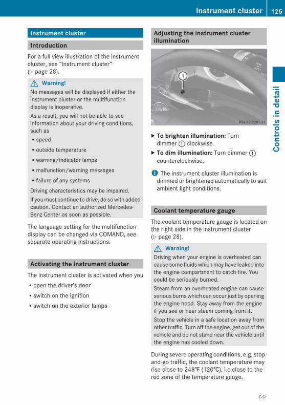
Instrument cluster
IntroductionFor a full view illustration of the instrumentcluster, see “Instrument cluster”(Y page 28).
G Warning!No messages will be displayed if either theinstrument cluster or the multifunctiondisplay is inoperative.As a result, you will not be able to seeinformation about your driving conditions,such asRspeedRoutside temperatureRwarning/indicator lampsRmalfunction/warning messagesRfailure of any systems
Driving characteristics may be impaired.If you must continue to drive, do so with addedcaution. Contact an authorized Mercedes-Benz Center as soon as possible.
The language setting for the multifunctiondisplay can be changed via COMAND, seeseparate operating instructions.
Activating the instrument clusterThe instrument cluster is activated when youRopen the driver’s doorRswitch on the ignitionRswitch on the exterior lamps
Adjusting the instrument cluster illumination
X To brighten illumination: Turndimmer : clockwise.
X To dim illumination: Turn dimmer :counterclockwise.
i The instrument cluster illumination isdimmed or brightened automatically to suitambient light conditions.
Coolant temperature gaugeThe coolant temperature gauge is located onthe right side in the instrument cluster(Y page 28).
G Warning!Driving when your engine is overheated cancause some fluids which may have leaked intothe engine compartment to catch fire. Youcould be seriously burned.Steam from an overheated engine can causeserious burns which can occur just by openingthe engine hood. Stay away from the engineif you see or hear steam coming from it.Stop the vehicle in a safe location away fromother traffic. Turn off the engine, get out of thevehicle and do not stand near the vehicle untilthe engine has cooled down.
During severe operating conditions, e.g. stop-and-go traffic, the coolant temperature mayrise close to 248‡ (120†), i.e close to thered zone of the temperature gauge.
Instrument cluster 125
Cont
rols
in d
etai
l
212_AKB; 2; 41, en-USd2ureepe, Version: 2.11.8.1
2009-07-17T09:14:21+02:00 - Seite 125
Z

! Excessive coolant temperature triggers awarning in the multifunction display.The engine should not be operated with acoolant temperature above 248‡ (120†),i.e. in the red zone of the coolanttemperature gauge. Doing so may causeserious engine damage which is notcovered by the Mercedes-Benz LimitedWarranty.
TachometerThe red marking on the tachometer(Y page 28) denotes excessive engine speed.
! Avoid driving at excessive engine speeds,as it may result in serious engine damagethat is not covered by the Mercedes-BenzLimited Warranty.
To help protect the engine, the fuel supply isinterrupted if the engine is operated withinthe red marking.
Outside temperature indicatorThe outside temperature indicator isdisplayed in the multifunction display(Y page 128).
G Warning!The outside temperature indicator is notdesigned to serve as an ice-warning deviceand is therefore unsuitable for that purpose.Indicated temperatures just above thefreezing point do not guarantee that the roadsurface is free of ice. The road may still be icy,especially in wooded areas or on bridges.
Fuel gaugeThe fuel gauge is on the left-hand side of theinstrument cluster (Y page 28). Once the fuellevel has fallen below the reserve mark, theyellow fuel tank reserve warning lamp 8for the fuel reserve comes on.
Control system
IntroductionThe control system is activated as soon as thestarter switch is in position 2.The control system enables you to call upinformation about your vehicle and to changevehicle settings.For example, you can use the control systemto find out when your vehicle is next due formaintenance service, to call up statisticaldata on your vehicle, and much more.
G Warning!A driver’s attention to the road and trafficconditions must always be his/her primaryfocus when driving.For your safety and the safety of others,selecting features through the multifunctionsteering wheel should only be done by thedriver when traffic and road conditions permitit to be done safely.Bear in mind that at a speed of just 30 mph(approximately 50 km/h), your vehicle iscovering a distance of 44 feet (approximately14 m) every second.
The control system relays information to themultifunction display.
Multifunction steering wheelThe displays in the multifunction display andthe settings in the control system arecontrolled by using the buttons on themultifunction steering wheel.
126 Control systemCo
ntro
ls in
det
ail
212_AKB; 2; 41, en-USd2ureepe, Version: 2.11.8.1
2009-07-17T09:14:21+02:00 - Seite 126

: Multifunction display
; Press button~ to end a call
to reject an incoming call6 to answer a call
to dial9
to redial98 to mute
Press buttonWX
to set the volumeto operate the RACETIMER10
= Press button? to activate the Voice Control
System11
? Press button briefly% to cancel the Voice Control
System11
to go backto confirm messages
Press and hold button% to select the standard display
A Press button;=
to call up line for menus and toselect menus
Press button briefly9:
to select submenu or scrollthrough listswithin Audio menu to selectprevious or next track, scene orstored stationwithin Tel menu to switch tothe phone book and select aname or number
Press and hold button9:
within Audio menu to select atrack or scene with quicksearch or to select previous ornext station in station list orwave bandwithin Tel menu to start thequick search in the phone book
Press buttona to confirm selection or
messages
Depending on the selected menu, pressingthe buttons on the multifunction steeringwheel will alter what appears in themultifunction display.The information available in the multifunctiondisplay is arranged in menus andaccompanying functions and submenus.The individual functions are then found withinthe relevant menu (radio or CD operationsunder Audio, for example). These functions
9 Function only available in telephone menu.10 AMG vehicles only.11 Function only available in vehicles with Voice Control System.
Control system 127
Cont
rols
in d
etai
l
212_AKB; 2; 41, en-USd2ureepe, Version: 2.11.8.1
2009-07-17T09:14:21+02:00 - Seite 127
Z

serve to call up relevant information or tocustomize the settings for your vehicle.It is helpful to think of the menus, and thefunctions within each menu, as beingarranged in a circular pattern.In the Sett. menu, instead of functions, youwill find a number of submenus for calling upand changing settings. For instructions onusing these submenus, see “Settings menu”(Y page 139).The number of menus available in the systemdepends on which optional equipment isinstalled in your vehicle.
Using the control systemX To select a menu: Press button =
or ;.X To select a submenu: Press button :
or 9.X To go to the next higher menu level:
Press button %.X To select the standard display: Press
button % repeatedly until the standarddisplay featuring the odometer andspeedometer appears.
orX Press and hold button % until the
standard display featuring the tripodometer and the main odometer appears.
X To confirm selection: Press button a.X To confirm display message: Press
button a or %.The control system saves certain displaymessages. Calling up display messages(Y page 139).
For information about warning andmalfunction messages appearing in themultifunction display (Y page 272).
Multifunction display
: Text field; Line for main menus= Automatic transmission program mode
indicator? Transmission position/gear range
indicatorA Outside temperature indicator/additional
speedometerSettings, functions, submenus as well as anymalfunctions appear in the text field.For more information on menus displayed inthe multifunction display, see “Menus andsubmenus” (Y page 129).
i E 63 AMG: The lower part of themultifunction display will vary from the themultifunction display shown. For moreinformation, see (Y page 118).
128 Control systemCo
ntro
ls in
det
ail
212_AKB; 2; 41, en-USd2ureepe, Version: 2.11.8.1
2009-07-17T09:14:21+02:00 - Seite 128
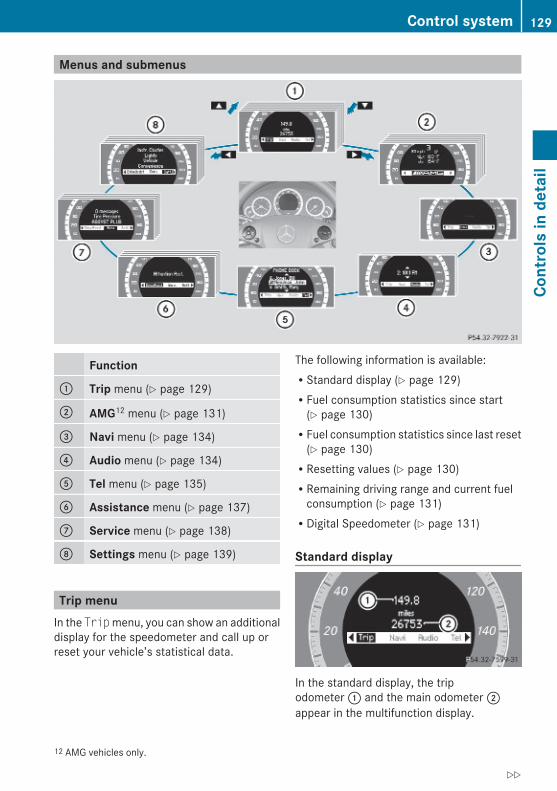
Menus and submenus
Function
: Trip menu (Y page 129)
; AMG12 menu (Y page 131)
= Navi menu (Y page 134)
? Audio menu (Y page 134)
A Tel menu (Y page 135)
B Assistance menu (Y page 137)
C Service menu (Y page 138)
D Settings menu (Y page 139)
Trip menuIn the Trip menu, you can show an additionaldisplay for the speedometer and call up orreset your vehicle’s statistical data.
The following information is available:RStandard display (Y page 129)RFuel consumption statistics since start
(Y page 130)RFuel consumption statistics since last reset
(Y page 130)RResetting values (Y page 130)RRemaining driving range and current fuel
consumption (Y page 131)RDigital Speedometer (Y page 131)
Standard display
In the standard display, the tripodometer : and the main odometer ;appear in the multifunction display.
12 AMG vehicles only.
Control system 129
Cont
rols
in d
etai
l
212_AKB; 2; 41, en-USd2ureepe, Version: 2.11.8.1
2009-07-17T09:14:21+02:00 - Seite 129
Z

If another display appears instead of thestandard display:X Press button = or ; to select theTrip menu.
orX Press button % repeatedly until the
standard display appears.orX Press and hold button % until the
standard display appears.
Fuel consumption statistics since start X Press button = or ; to select theTrip menu.
X Press button : or 9 to select From Start.
: Distance driven since start; Time elapsed since start= Average speed since start? Average fuel consumption since start
All statistics stored since the last engine startwill be reset approximately 4 hours after theSmartKey in the starter switch is turned toposition 0 or removed from the starter switch.Resetting will not occur if you turn theSmartKey back to position 1 or 2 within thistime period.The fuel consumption statistics since startreset automatically to 0 after 9 999 miles or999 hours, whichever occurs first.
Fuel consumption statistics since last resetX Press button = or ; to select theTrip menu.
X Press button : or 9 to select From Reset.
: Distance driven since last reset; Time elapsed since last reset= Average speed since last reset? Average fuel consumption since last reset
The fuel consumption statistics since lastreset reset automatically to 0 after99 999 miles or 9 999 hours, whicheveroccurs first.
Resetting valuesYou can reset the values for the followingfunctions:RTrip odometerRFuel consumption statistics since startRFuel consumption statistics since last resetX Press button = or ; to select theTrip menu.
X Press button : or 9 to select thefunction you wish to reset.
X Press button a.
Example illustration: Reset fuel consumptionstatistics since start
130 Control systemCo
ntro
ls in
det
ail
212_AKB; 2; 41, en-USd2ureepe, Version: 2.11.8.1
2009-07-17T09:14:21+02:00 - Seite 130

X Press button : to select Yes.X Press button a to confirm.
Remaining driving range and current fuel consumptionX Press button = or ; to select theTrip menu.
X Press button : or 9 to select theestimated remaining driving range andcurrent fuel consumption display.Note that the values are calculated basedon the current fuel tank level and thecurrent driving style. Make sure to refuel intime.If only very little fuel is left in the tank, avehicle at the fuel pump C appearsinstead of the estimated remaining drivingrange.
: Current fuel consumption13
; Estimated remaining driving range
Digital speedometerX Press button = or ; to select theTrip menu.
X Press button : or 9 to select thedigital speedometer.
AMG menuThis function is only available in AMGvehicles.X Press button = or ; to select theAMG menu.
: Digital speedometer; Gear indicator= Upshift indicator? Engine oil temperature indicatorA Coolant temperature indicator
The engine oil temperature flashes if theengine oil temperature has not yet reached176‡ (80†). During this time, avoid drivingat full engine speed.The upshift indicator = indicates that theengine has reached the overrevving range.The upshift indicator = blocks othermessages in the multifunction display untilyou have shifted up.Use buttons : or 9 to select thefollowing functions in the AMG menu:RSETUP (Y page 132)RRACETIMER (Y page 132)ROverall analysis (Y page 133)RLap analysis (Y page 133)
13 Not available on AMG vehicles.
Control system 131
Cont
rols
in d
etai
l
212_AKB; 2; 41, en-USd2ureepe, Version: 2.11.8.1
2009-07-17T09:14:21+02:00 - Seite 131
Z

SETUPX Press button = or ; to select theAMG menu.
X Press button 9 to select SETUP.orX Tap the AMG button on the center console
(Y page 165).
i You can store and call up automatictransmission program mode andsuspension style settings with the AMGbutton on the center console. For moreinformation, see (Y page 165).
: Automatic transmission program modeindicator
; ESC mode indicator= Suspension style indicator
RACETIMER
G Warning!The RACETIMER feature is only for use onroads and in conditions where high speeddriving is permitted. Racing on public roads isprohibited under all circumstances. The driveris and must always remain responsible forfollowing posted speed limits.
The RACETIMER allows you to time and savedriving stretches.X Press button = or ; to select theAMG menu.
X Press button 9 repeatedly until theRACETIMER appears in the multifunctiondisplay.
: RACETIMER; Lap number
You can start the RACETIMER when theengine is running or the starter switch is inposition 2 (Y page 85).While the RACETIMER is being displayed, youcannot adjust the audio volume using buttonsW or X.X Starting: Press button W.X Displaying intermediate time: Press
button X while the timer is running.The intermediate time is shown for5 seconds.
X Stopping: Press button W.When you stop the vehicle and turn theSmartKey to position 1 (Y page 85) or, invehicles with KEYLESS-GO, turn off theengine and do not open the driver’s door, theRACETIMER stops timing. Timing is resumedwhen you press button W after switchingthe ignition back on or restarting the engine.
Saving lap time and starting a new lapYou can save up to 16 laps.X Press button X while the timer is
running.The intermediate time will be shown for5 seconds.
X Press button X within 5 seconds.The intermediate time shown will be savedas a lap time.The RACETIMER begins timing the new lap.The new lap begins to be timed as soon asthe intermediate time is called up.
132 Control systemCo
ntro
ls in
det
ail
212_AKB; 2; 41, en-USd2ureepe, Version: 2.11.8.1
2009-07-17T09:14:21+02:00 - Seite 132
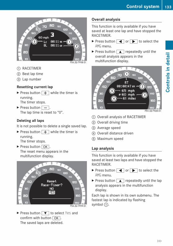
: RACETIMER; Best lap time= Lap number
Resetting current lapX Press button W while the timer is
running.The timer stops.
X Press button X.The lap time is reset to “0”.
Deleting all lapsIt is not possible to delete a single saved lap.X Press button W while the timer is
running.The timer stops.
X Press button a.The reset menu appears in themultifunction display.
X Press button : to select Yes andconfirm with button a.The saved laps are deleted.
Overall analysisThis function is only available if you havesaved at least one lap and have stopped theRACETIMER.X Press button = or ; to select theAMG menu.
X Press button 9 repeatedly until theoverall analysis appears in themultifunction display.
: Overall analysis of RACETIMER; Overall driving time= Average speed? Overall distance drivenA Maximum speed
Lap analysisThis function is only available if you havesaved at least two laps and have stopped theRACETIMER.X Press button = or ; to select theAMG menu.
X Press button 9 repeatedly until the lapanalysis appears in the multifunctiondisplay.
Each lap is shown in its own submenu. Thefastest lap is indicated by flashingsymbol :.
Control system 133
Cont
rols
in d
etai
l
212_AKB; 2; 41, en-USd2ureepe, Version: 2.11.8.1
2009-07-17T09:14:21+02:00 - Seite 133
Z
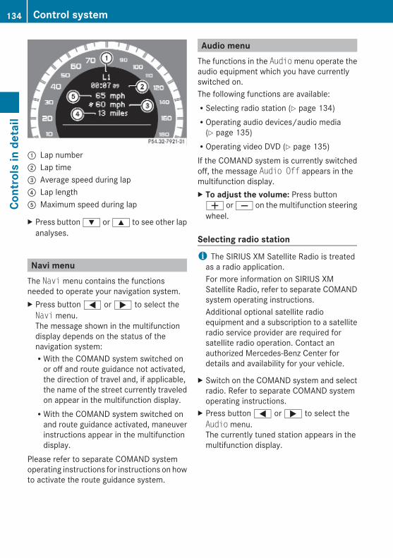
: Lap number; Lap time= Average speed during lap? Lap lengthA Maximum speed during lap
X Press button : or 9 to see other lapanalyses.
Navi menuThe Navi menu contains the functionsneeded to operate your navigation system.X Press button = or ; to select theNavi menu.The message shown in the multifunctiondisplay depends on the status of thenavigation system:RWith the COMAND system switched on
or off and route guidance not activated,the direction of travel and, if applicable,the name of the street currently traveledon appear in the multifunction display.RWith the COMAND system switched on
and route guidance activated, maneuverinstructions appear in the multifunctiondisplay.
Please refer to separate COMAND systemoperating instructions for instructions on howto activate the route guidance system.
Audio menuThe functions in the Audio menu operate theaudio equipment which you have currentlyswitched on.The following functions are available:RSelecting radio station (Y page 134)ROperating audio devices/audio media
(Y page 135)ROperating video DVD (Y page 135)If the COMAND system is currently switchedoff, the message Audio Off appears in themultifunction display.X To adjust the volume: Press buttonW or X on the multifunction steeringwheel.
Selecting radio station i The SIRIUS XM Satellite Radio is treated
as a radio application.For more information on SIRIUS XMSatellite Radio, refer to separate COMANDsystem operating instructions.Additional optional satellite radioequipment and a subscription to a satelliteradio service provider are required forsatellite radio operation. Contact anauthorized Mercedes-Benz Center fordetails and availability for your vehicle.
X Switch on the COMAND system and selectradio. Refer to separate COMAND systemoperating instructions.
X Press button = or ; to select theAudio menu.The currently tuned station appears in themultifunction display.
134 Control systemCo
ntro
ls in
det
ail
212_AKB; 2; 41, en-USd2ureepe, Version: 2.11.8.1
2009-07-17T09:14:21+02:00 - Seite 134

Example illustration for FM radio: Stored memory position; Station frequency= Wave band setting
X Selecting next or previous stored station: Press button : or 9 brieflyto select a stored station.
X Selecting next or previous station in wave band: Press and hold button : or9 to select a station.
You can only store new stations using thecorresponding feature on the radio. Refer toseparate COMAND system operatinginstructions.You can also operate the radio in the usualmanner.
Operating audio devices/audio mediaX Switch on the COMAND system and select
the audio device or audio media. Refer toseparate COMAND system operatinginstructions.
X Press button = or ; to select theAudio menu. The settings for the currentlybeing played audio device/audio mediaappear in the multifunction display.
Example illustration: Disc number; Current track
X Selecting next or previous track: Pressbutton : or 9 briefly.
X Selecting a track from the track list (quick search): Press and holdbutton : or 9.
The current track does not appear duringAudio AUX mode operation.
Operating video DVDX Switch on the COMAND system and select
DVD-Video. Refer to separate COMANDsystem operating instructions.
X Press button = or ; to select theAudio menu.
: Disc number; Current scene
X Selecting next or previous scene: Pressbutton : or 9 briefly.
X Selecting a scene from the scene list (quick search): Press and holdbutton : or 9.
Tel menu
G Warning!A driver’s attention to the road must alwaysbe his/her primary focus when driving. Foryour safety and the safety of others, werecommend that you pull over to a safelocation and stop before placing or taking atelephone call. If you choose to use thetelephone while driving, please use the hands-free device and only use the telephone whenweather, road and traffic conditions permit.
Control system 135
Cont
rols
in d
etai
l
212_AKB; 2; 41, en-USd2ureepe, Version: 2.11.8.1
2009-07-17T09:14:21+02:00 - Seite 135
Z

Some jurisdictions prohibit the driver fromusing a mobile phone while driving a vehicle.Bear in mind that at a speed of just 30 mph(approximately 50 km/h), your vehicle iscovering a distance of 44 feet (approximately14 m) every second.
You can connect your telephone to theCOMAND system via Bluetooth®, seeseparate COMAND system operatinginstructions.X Switch on the COMAND system.
Refer to separate COMAND systemoperating instructions.
X Press button = or ; to select theTel menu.One of the following messages will appearin the multifunction display:RNo Service: No network is available.RReady for Bluetooth Telephony...:
The telephone has not been connectedto the COMAND system via Bluetooth®
yet.X Connect the telephone to the
COMAND system via Bluetooth®.
RPhone READY or name of the networkprovider (if available): The telephone hasfound a network and is ready for use. Youcan operate it using the control system.
Answering a call When your telephone is ready to receive calls,you can answer a call at any time. In themultifunction display you will then see thefollowing message:
Example illustration
X Press button 6.You have answered the call.
The caller’s number appears only if it istransmitted.The caller’s name appears only if the numberand the name are stored in the phone book.
Ending a call or rejecting an incoming callX Press button ~.
Dialing a number from the phone book When your telephone is ready to receive calls,you may select and dial a number from thephone book at any time.
i To use the phone book of the COMANDsystem you can import business cards(vCards) from external Bluetooth® phonesinto your COMAND system’s phone book,see separate COMAND operatinginstructions.
X Press button = or ; to select theTel menu.
X Press button : or 9 or a toswitch to the phone book.The stored names are displayed inascending alphabetical order.
X Press button : or 9 to select thedesired entry.If you press and hold button : or9 the system scrolls rapidly through thelist of names (quick search). After holdingbutton : or 9 for a short while thescrolling speed increases. Release thebutton to stop the quick search. The searchstops automatically at the end of the list.
136 Control systemCo
ntro
ls in
det
ail
212_AKB; 2; 41, en-USd2ureepe, Version: 2.11.8.1
2009-07-17T09:14:21+02:00 - Seite 136
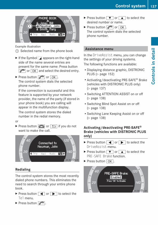
Example illustration: Selected name from the phone book
X If the Symbol G appears on the right-handside of the name several entries arepresent for the same name: Press button6 or a and select the desired entry.
X Press button 6 or a.The control system dials the selectedphone number.If the connection is successful and thisfeature is supported by your networkprovider, the name of the party (if stored inyour phone book) you are calling willappear in the multifunction display.The control system stores the dialednumber in the redial memory.
orX Press button ~ or % if you do not
want to make the call.
Redialing The control system stores the most recentlydialed phone numbers. This eliminates theneed to search through your entire phonebook.X Press button = or ; to select theTel menu.
X Press button 6.
X Press button : or 9 to select thedesired number or name.
X Press button 6 or a.The control system dials the selectedphone number.
Assistance menuIn the DriveAssist menu, you can changethe settings of your driving systems.The following functions are available:RDisplaying distance graphic, DISTRONIC
PLUS (Y page 152)RActivating/deactivating PRE-SAFE® Brake
(vehicles with DISTRONIC PLUS only)(Y page 137)RSwitching ATTENTION ASSIST on or off
(Y page 138)RSwitching Blind Spot Assist on or off
(Y page 138)RSwitching Lane Keeping Assist on or off
(Y page 138)
Activating/deactivating PRE-SAFE® Brake (vehicles with DISTRONIC PLUS only) X Press button = or ; to select theDriveAssist menu.
X Press button : or 9 to select thePRE-SAFE Brake function.
X Press button a.
Control system 137
Cont
rols
in d
etai
l
212_AKB; 2; 41, en-USd2ureepe, Version: 2.11.8.1
2009-07-17T09:14:21+02:00 - Seite 137
Z

X Press button a again if you would liketo change the current status.After the function has been activated, thePRE-SAFE® Brake indicator Ä appearsin the lower part of the multifunctiondisplay. When the HOLD function isswitched on, the PRE-SAFE® Brakeindicator Ä will not appear.
For more information on PRE-SAFE® Brake,see (Y page 69).
Switching ATTENTION ASSIST on or off X Press button = or ; to select theDriveAssist menu.
X Press button : or 9 to select theAttention Asst. function
X Press button a.
X Press button a again if you would liketo change the current status.After the function has been activated, theATTENTION ASSIST indicator À appearson the left-hand side of the multifunctiondisplay.
For more information on ATTENTION ASSIST,see (Y page 178).
Switching Blind Spot Assist on or off X Press button = or ; to select theDriveAssist menu.
X Press button : or 9 to select theBlind Spot Asst. function
X Press button a.
X Press button a again if you would liketo change the current status.Depending on the previous status, Blind Spot Assist: will be Enabled orDisabled.
For more information on Blind Spot Assist,see (Y page 175).
Switching Lane Keeping Assist on or off X Press button = or ; to select theDriveAssist menu.
X Press button : or 9 to select theLane Keep. Asst. function
X Press button a.
X Press button a again if you would liketo change the current status.After the function has been activated, theLane Keeping Assist indicator Ãappears in the lower part of themultifunction display.
For more information on Lane KeepingAssistance, see (Y page 177).
Service menuIn the Serv. menu the following functions areavailable:
138 Control systemCo
ntro
ls in
det
ail
212_AKB; 2; 41, en-USd2ureepe, Version: 2.11.8.1
2009-07-17T09:14:21+02:00 - Seite 138

RVehicle status message memory(Y page 139)RRestarting the tire pressure loss warning
system (Canada only) (Y page 233)RChecking tire inflation pressure
electronically with the Advanced TPMS(Y page 233)RCalling up the maintenance service
indicator display (Y page 259)
Vehicle status message memory Use the vehicle status message memoryfunction to scan malfunction and warningmessages that may be stored in the system.Such messages appear in the multifunctiondisplay and are based on conditions orsystem status the vehicle’s system hasrecorded.
G Warning!Malfunction and warning messages are onlyindicated for certain systems and areintentionally not very detailed. Themalfunction and warning messages aresimply a reminder with respect to theoperation of certain systems. They do notreplace the owner’s and/or driver’sresponsibility to maintain the vehicle’soperating safety. Have all requiredmaintenance and safety checks performed onthe vehicle. Bring the vehicle to an authorizedMercedes-Benz Center to address themalfunction and warning messages.
X Press button = or ; to select theServ. menu.If conditions have occurred causing statusmessages to be recorded, the number ofmessages appears in the multifunctiondisplay:
X Press button : or 9 to select themessages function.
X Press button a to confirm.The stored messages will now be displayedin the order in which they have occurred.For malfunction and warning messages,see “Vehicle status messages in themultifunction display” (Y page 272).
X Use button : or 9 to scroll throughthe messages.
If you turn the SmartKey in the starter switchto position 0 and then back to position 2, allmessages will be deleted from the messagememory.
Settings menu
IntroductionIn the Sett. menu there are two functions:The function Factory Setting(Y page 139), with which you can reset thesettings to the original factory settings and acollection of submenus (Y page 140) withwhich you can make individual settings foryour vehicle.
Resetting to factory settingsYou can reset most of the settings of thesubmenus to the factory settings.For safety reasons, the function Daytime Running Lamps in the Lights submenucannot be reset while driving.X Press button = or ; to select theSett. menu.
Control system 139
Cont
rols
in d
etai
l
212_AKB; 2; 41, en-USd2ureepe, Version: 2.11.8.1
2009-07-17T09:14:21+02:00 - Seite 139
Z

X Press button : or 9 to select theFactory Setting function.
X Press button a.The function Reset All Settings?appears in the multifunction display.
X Press button : or 9 to select Yes orNo. Select Yes if you want to reset tofactory settings.
X Press button a to confirm.The confirmation message appears in themultifunction display.
Submenus in the Settings menuX Press button = or ; to select theSett. menu.
X Press button : or 9 to select asubmenu.
Scroll down with button :, scroll up withbutton 9.With the selection marker on the desiredsubmenu, use the button a to access theindividual functions within that submenu.Once within the submenu, you can use button9 to move to the next function orbutton : to move to the previous functionwithin that submenu.The following lists show what settings can bechanged within the various menus. Detailed
instructions on making individual settings canbe found on the following pages.
Instrument cluster submenuRSelecting speedometer display mode
(Y page 141)RPermanent display (speed display or
outside temperature) (Y page 141)
Lights submenuRSwitching daytime running lamp mode on
or off (USA only) (Y page 141)RSwitching Adaptive Highbeam Assist on or
off (Y page 142)RSwitching locator lighting on or off
(Y page 142)RSetting ambient lighting (Y page 143)RSwitching interior lighting delayed shut-off
on or off (Y page 143)
Vehicle submenuRSwitching automatic central locking on or
off (Y page 144)RSwitching the radar sensors on or off
(Y page 144)
Convenience submenuRActivating easy-entry/exit feature
(Y page 145)RActivating/deactivating seat belt
adjustment function (Y page 145)
Instrument cluster submenuAccess the Instr. Cluster submenu viathe Sett. menu. Use the Instr. Clustersubmenu to change the instrument clusterdisplay settings.The following functions are available:RSelecting speedometer display mode
(Y page 141)RPermanent display (speed display or
outside temperature) (Y page 141)
140 Control systemCo
ntro
ls in
det
ail
212_AKB; 2; 41, en-USd2ureepe, Version: 2.11.8.1
2009-07-17T09:14:21+02:00 - Seite 140

Selecting speedometer display mode X Press = or ; to select the Sett.
menu.X Press button : or 9 to select theInstr. Cluster submenu.
X Press button a.X Press button : or 9 to select theDisplay Unit Speed-/Odometer:function.The current setting is shown.
X Press button a to change the setting.Depending on the previous setting theDisplay Unit Speed-/Odometer: will beset to miles or km.
The selected display unit is valid for:ROdometer and trip odometerRTrip computerRDigital speedometer in the trip menuRCruise controlRNavigation displays
Permanent displayYou can use the Permanent Display:function to choose to display either theoutside temperature or the speed inkilometers (USA) or miles (Canada)permanently.X Press button = or ; to select theSett. menu.
X Press button : or 9 to select theInstr. Cluster submenu.
X Press button a.X Press button : or 9 to select thePermanent Display: function.The current setting is shown.
X Press button a to change the currentstatus.Depending on the previous status, thePermanent Display: will be switchedbetween Outside temperature orSpeedometer (km/h) (USA)/Speedometer (miles) (Canada).
Lights submenuAccess the Lights submenu via the Sett.menu. Use the submenu to change the lampand lighting settings on your vehicle.The following functions are available:RSwitching daytime running lamp mode on
or off (USA only) (Y page 141)RSwitching Adaptive Highbeam Assist on or
off (Y page 142)RSetting ambient lighting (Y page 143)RSwitching locator lighting function on or off
(Y page 142)RSwitching interior lighting delayed shut-off
on or off (Y page 143)
Switching daytime running lamp mode on or off (USA only) X Press button = or ; to select theSett. menu.
X Press button : or 9 to select theLights submenu.
X Press button a.X Press button : or 9 to select theDaytime Running Lamps: function.The current setting Enabled or Disabledis shown.
Control system 141
Cont
rols
in d
etai
l
212_AKB; 2; 41, en-USd2ureepe, Version: 2.11.8.1
2009-07-17T09:14:21+02:00 - Seite 141
Z
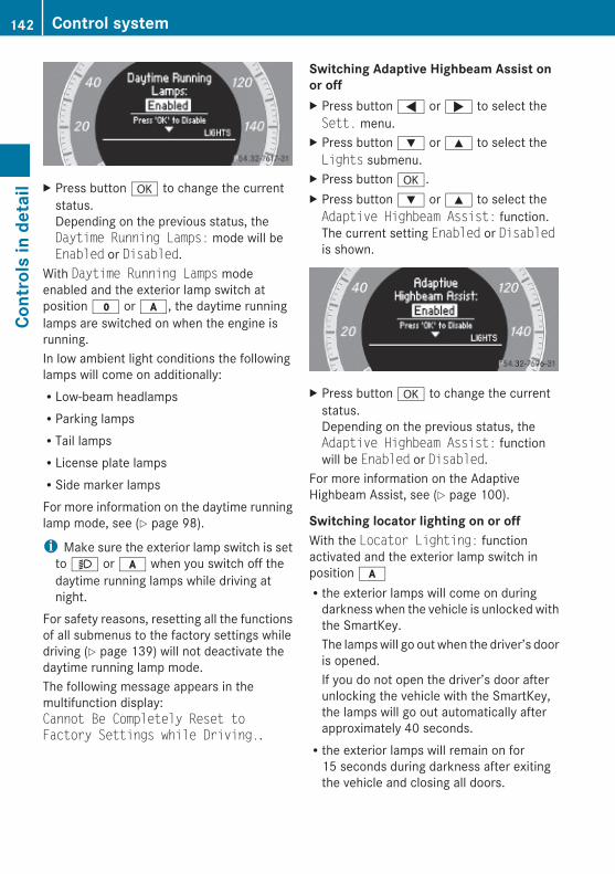
X Press button a to change the currentstatus.Depending on the previous status, theDaytime Running Lamps: mode will beEnabled or Disabled.
With Daytime Running Lamps modeenabled and the exterior lamp switch atposition $ or c, the daytime runninglamps are switched on when the engine isrunning.In low ambient light conditions the followinglamps will come on additionally:RLow-beam headlampsRParking lampsRTail lampsRLicense plate lampsRSide marker lampsFor more information on the daytime runninglamp mode, see (Y page 98).
i Make sure the exterior lamp switch is setto M or c when you switch off thedaytime running lamps while driving atnight.
For safety reasons, resetting all the functionsof all submenus to the factory settings whiledriving (Y page 139) will not deactivate thedaytime running lamp mode.The following message appears in themultifunction display:Cannot Be Completely Reset to Factory Settings while Driving..
Switching Adaptive Highbeam Assist on or off X Press button = or ; to select theSett. menu.
X Press button : or 9 to select theLights submenu.
X Press button a.X Press button : or 9 to select theAdaptive Highbeam Assist: function.The current setting Enabled or Disabledis shown.
X Press button a to change the currentstatus.Depending on the previous status, theAdaptive Highbeam Assist: functionwill be Enabled or Disabled.
For more information on the AdaptiveHighbeam Assist, see (Y page 100).
Switching locator lighting on or off With the Locator Lighting: functionactivated and the exterior lamp switch inposition cRthe exterior lamps will come on during
darkness when the vehicle is unlocked withthe SmartKey.The lamps will go out when the driver’s dooris opened.If you do not open the driver’s door afterunlocking the vehicle with the SmartKey,the lamps will go out automatically afterapproximately 40 seconds.Rthe exterior lamps will remain on for
15 seconds during darkness after exitingthe vehicle and closing all doors.
142 Control systemCo
ntro
ls in
det
ail
212_AKB; 2; 41, en-USd2ureepe, Version: 2.11.8.1
2009-07-17T09:14:21+02:00 - Seite 142
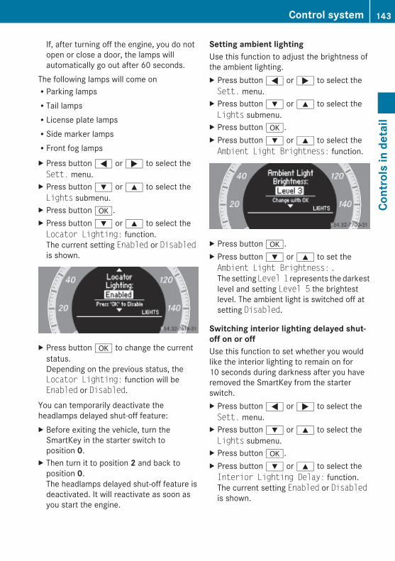
If, after turning off the engine, you do notopen or close a door, the lamps willautomatically go out after 60 seconds.
The following lamps will come onRParking lampsRTail lampsRLicense plate lampsRSide marker lampsRFront fog lampsX Press button = or ; to select theSett. menu.
X Press button : or 9 to select theLights submenu.
X Press button a.X Press button : or 9 to select theLocator Lighting: function.The current setting Enabled or Disabledis shown.
X Press button a to change the currentstatus.Depending on the previous status, theLocator Lighting: function will beEnabled or Disabled.
You can temporarily deactivate theheadlamps delayed shut-off feature:X Before exiting the vehicle, turn the
SmartKey in the starter switch toposition 0.
X Then turn it to position 2 and back toposition 0.The headlamps delayed shut-off feature isdeactivated. It will reactivate as soon asyou start the engine.
Setting ambient lightingUse this function to adjust the brightness ofthe ambient lighting.X Press button = or ; to select theSett. menu.
X Press button : or 9 to select theLights submenu.
X Press button a.X Press button : or 9 to select theAmbient Light Brightness: function.
X Press button a.X Press button : or 9 to set theAmbient Light Brightness: .The setting Level 1 represents the darkestlevel and setting Level 5 the brightestlevel. The ambient light is switched off atsetting Disabled.
Switching interior lighting delayed shut-off on or off Use this function to set whether you wouldlike the interior lighting to remain on for10 seconds during darkness after you haveremoved the SmartKey from the starterswitch.X Press button = or ; to select theSett. menu.
X Press button : or 9 to select theLights submenu.
X Press button a.X Press button : or 9 to select theInterior Lighting Delay: function.The current setting Enabled or Disabledis shown.
Control system 143
Cont
rols
in d
etai
l
212_AKB; 2; 41, en-USd2ureepe, Version: 2.11.8.1
2009-07-17T09:14:21+02:00 - Seite 143
Z
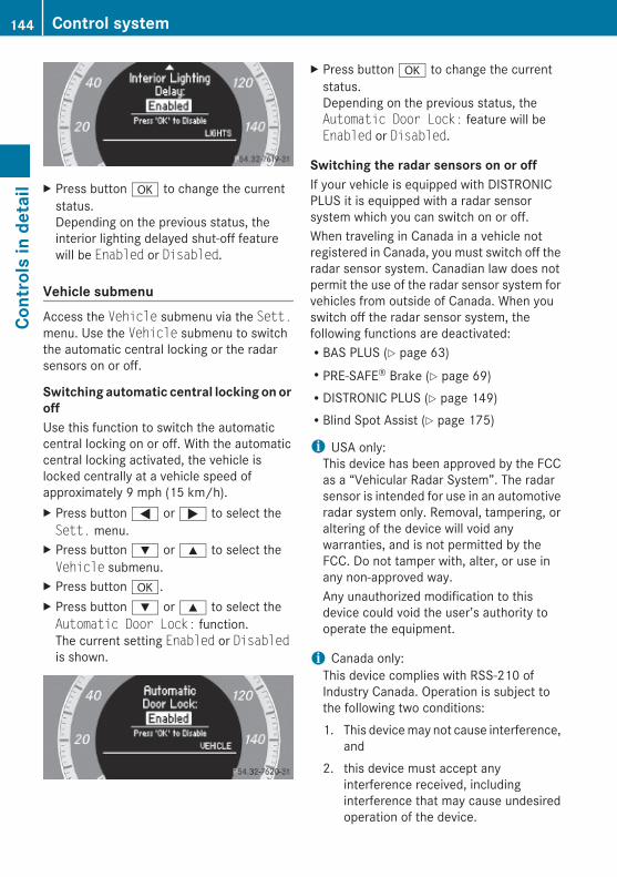
X Press button a to change the currentstatus.Depending on the previous status, theinterior lighting delayed shut-off featurewill be Enabled or Disabled.
Vehicle submenuAccess the Vehicle submenu via the Sett.menu. Use the Vehicle submenu to switchthe automatic central locking or the radarsensors on or off.
Switching automatic central locking on or off Use this function to switch the automaticcentral locking on or off. With the automaticcentral locking activated, the vehicle islocked centrally at a vehicle speed ofapproximately 9 mph (15 km/h).X Press button = or ; to select theSett. menu.
X Press button : or 9 to select theVehicle submenu.
X Press button a.X Press button : or 9 to select theAutomatic Door Lock: function.The current setting Enabled or Disabledis shown.
X Press button a to change the currentstatus.Depending on the previous status, theAutomatic Door Lock: feature will beEnabled or Disabled.
Switching the radar sensors on or off If your vehicle is equipped with DISTRONICPLUS it is equipped with a radar sensorsystem which you can switch on or off.When traveling in Canada in a vehicle notregistered in Canada, you must switch off theradar sensor system. Canadian law does notpermit the use of the radar sensor system forvehicles from outside of Canada. When youswitch off the radar sensor system, thefollowing functions are deactivated:RBAS PLUS (Y page 63)RPRE-SAFE® Brake (Y page 69)RDISTRONIC PLUS (Y page 149)RBlind Spot Assist (Y page 175)
i USA only:This device has been approved by the FCCas a “Vehicular Radar System”. The radarsensor is intended for use in an automotiveradar system only. Removal, tampering, oraltering of the device will void anywarranties, and is not permitted by theFCC. Do not tamper with, alter, or use inany non-approved way.Any unauthorized modification to thisdevice could void the user’s authority tooperate the equipment.
i Canada only:This device complies with RSS-210 ofIndustry Canada. Operation is subject tothe following two conditions:1. This device may not cause interference,
and2. this device must accept any
interference received, includinginterference that may cause undesiredoperation of the device.
144 Control systemCo
ntro
ls in
det
ail
212_AKB; 2; 41, en-USd2ureepe, Version: 2.11.8.1
2009-07-17T09:14:21+02:00 - Seite 144

Removal, tampering, or altering of thedevice will void any warranties, and is notpermitted. Do not tamper with, alter, or usein any non-approved way.Any unauthorized modification to thisdevice could void the user’s authority tooperate the equipment.
X Press button = or ; to select theSett. menu.
X Press button : or 9 to select theVehicle submenu.
X Press button a.X Press button : or 9 to select theRadar Sensor (See Oper. Manual):function.The current setting Enabled or Disabledis shown.
X Press button a again if you would liketo change the current status.Depending on the previous status, theradar sensors will be switched on(Enabled) or off (Disabled).
i The selected status of the radar sensorsremains stored in memory even if theengine is turned off and restarted.
Convenience submenuAccess the Convenience submenu via theSett. menu. Use the Convenience submenuto activate the easy-entry/exit feature(Y page 145) or to activate the seat beltadjustment feature (Y page 145).
Activating easy-entry/exit feature Use this function to activate and deactivatethe easy-entry/exit feature (Y page 93).
G Warning!You must make sure no one can becometrapped or injured by the moving steeringwheel when the easy-entry/exit feature isactivated.To stop steering wheel movement, movesteering wheel adjustment stalk or press oneof the memory position buttons.Do not leave children unattended in thevehicle, or with access to an unlocked vehicle.Children could open the driver’s door andunintentionally activate the easy-entry/exitfeature, which could result in an accidentand/or serious personal injury.
X Press button = or ; to select theSett. menu.
X Press button : or 9 to select theConvenience submenu.
X Press button a.X Press button : or 9 to select theEasy Entry/Exit: function.The current setting Enabled or Disabledis shown.
X Press button a to change the currentstatus.Depending on the previous status, theEasy Entry/Exit: feature will beEnabled or Disabled.
Activating/deactivating seat belt adjustment functionUse this function to set the seat belts to beadjusted automatically with the driver’s orfront passenger seat belt fastened and thestarter switch in position 2.For more information on the seat beltadjustment function, see (Y page 51).
Control system 145
Cont
rols
in d
etai
l
212_AKB; 2; 41, en-USd2ureepe, Version: 2.11.8.1
2009-07-17T09:14:21+02:00 - Seite 145
Z

X Press button = or ; to select theSett. menu.
X Press button : or 9 to select theConvenience submenu.
X Press a.X Press button : or 9 to select theBelt Adjustment: function.The current setting Enabled or Disabledis shown.
X Press button a to change the currentstatus.Depending on the previous status, theBelt Adjustment: function will beEnabled or Disabled.
Driving systems
IntroductionRCruise controlRDISTRONIC PLUSRHill-start assist systemRHOLD functionRAIRMATIC (E 550 and E 550 4MATIC)RAll-wheel drive (4MATIC)RParktronic system with Parking GuidanceRRear view cameraRNight View Assist PlusRATTENTION ASSISTRBlind Spot AssistRLane Keeping Assist
RRACE START (E 63 AMG)RAMG adaptive sport suspension system
(E 63 AMG)The driving safety systems ABS, AdaptiveBrake, BAS, BAS PLUS, EBP, ESC and PRE-SAFE® Brake are described in the “Safety andsecurity” section (Y page 61).
Cruise controlThe cruise control maintains the speed youset for your vehicle automatically.The use of the cruise control is recommendedfor driving at a constant speed for extendedperiods of time.The currently set speed or last set speed(“Resume” function) appears in themultifunction display for approximately5 seconds. The corresponding cruise controlspeed segments from the selected speed tothe vehicle maximum speed in themultifunction display are illuminated.
G Warning!The cruise control is a convenience systemdesigned to assist the driver during vehicleoperation. The driver is and must alwaysremain responsible for the vehicle’s speedand for safe brake operation.Only use the cruise control if the road, traffic,and weather conditions make it advisable totravel at a constant speed.RThe use of the cruise control can be
dangerous on winding roads or in heavytraffic because conditions do not allow safedriving at a constant speed.RThe use of the cruise control can be
dangerous on slippery roads. Rapidchanges in tire traction can result in wheelspin and loss of control.RDeactivate the cruise control when driving
in fog.
The “Resume” function should only beoperated if the driver is fully aware of the
146 Driving systemsCo
ntro
ls in
det
ail
212_AKB; 2; 41, en-USd2ureepe, Version: 2.11.8.1
2009-07-17T09:14:21+02:00 - Seite 146
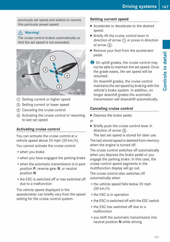
previously set speed and wishes to resumethis particular preset speed.
G Warning!The cruise control brakes automatically sothat the set speed is not exceeded.
: Setting current or higher speed ; Setting current or lower speed= Canceling the cruise control? Activating the cruise control or resuming
to last set speed
Activating cruise control You can activate the cruise control at avehicle speed above 20 mph (30 km/h).You cannot activate the cruise controlRwhen you brakeRwhen you have engaged the parking brakeRwhen the automatic transmission is in park
position P, reverse gear R, or neutralposition NRthe ESC is switched off or has switched off
due to a malfunctionThe vehicle speed displayed in thespeedometer can briefly vary from the speedsetting for the cruise control system.
Setting current speed X Accelerate or decelerate to the desired
speed.X Briefly lift the cruise control lever in
direction of arrow : or press in directionof arrow ;.
X Remove your foot from the acceleratorpedal.
i On uphill grades, the cruise control maynot be able to maintain the set speed. Oncethe grade eases, the set speed will beresumed.On downhill grades, the cruise controlmaintains the set speed by braking with thevehicle’s brake system. In addition, onlonger downhill grades the automatictransmission will downshift automatically.
Canceling cruise control X Depress the brake pedal.orX Briefly push the cruise control lever in
direction of arrow =.The last set speed is stored for later use.
The last stored speed is deleted from memorywhen the engine is turned off.The cruise control switches off automaticallywhen you depress the brake pedal or youengage the parking brake. In this case, thecruise control speed segments in themultifunction display will go out.The cruise control also switches offautomatically whenRthe vehicle speed falls below 20 mph
(30 km/h)Rthe ESC is in operationRthe ESC is switched off with the ESC switchRthe ESC has switched off due to a
malfunctionRyou shift the automatic transmission into
neutral position N while driving
Driving systems 147
Cont
rols
in d
etai
l
212_AKB; 2; 41, en-USd2ureepe, Version: 2.11.8.1
2009-07-17T09:14:21+02:00 - Seite 147
Z

The cruise control speed segments in themultifunction display goes out and anacoustic warning will sound. Observeadditional messages in the multifunctiondisplay that may appear.Depressing the accelerator pedal does notdeactivate the cruise control. After a briefacceleration (e.g. for passing), the cruisecontrol will resume the last set speed.
Changing the set speed
G Warning!Keep in mind that it may take a brief momentuntil the vehicle has made the necessaryadjustments.Increase or decrease the set vehicle speed toa value that the prevailing road conditions andlegal speed limits permit. Otherwise, suddenand unexpected acceleration or decelerationof the vehicle could cause an accident and/or serious injury to you and others.
You can increase or decrease the set speedin 1 mph (Canada: 1 km/h) increments or in5 mph (Canada: 10 km/h) increments.When you use the cruise control lever todecelerate, the brake system will brake thevehicle automatically if the engine’s brakingpower does not brake the vehicle sufficiently.
Adjustment in 1 mph (Canada: 1 km/h) incrementsi The set speed value is increased or
decreased in 1 mph (Canada: 1 km/h)increments each time you lift or press thecruise control lever up or down to theresistance point.
X Increasing: Briefly lift the cruise controllever up to the resistance point in directionof arrow :.
X Decreasing: Briefly press the cruisecontrol lever down to the resistance pointin direction of arrow ;.
X Release the cruise control lever.The new speed is set and the vehicle willaccelerate or decelerate.
Adjustment in 5 mph (Canada: 10 km/h) incrementsi The set speed value is increased or
decreased in 5 mph (Canada: 10 km/h)increments each time you lift or press thecruise control lever up or down past theresistance point.
X Increasing: Briefly lift the cruise controllever up past the resistance point indirection of arrow :.
X Decreasing: Briefly press the cruisecontrol lever down past the resistancepoint in direction of arrow ;.
X Release the cruise control lever.The new speed is set and the vehicle willaccelerate or decelerate. Keep in mind thatit may take a brief moment until the vehiclehas reached the set speed.
Setting stored speed (Resume function)
G Warning!The set speed stored in memory should onlybe set again if prevailing road conditions andlegal speed limits permit. Possibleacceleration or deceleration differencesarising from returning to the preset speedcould cause an accident and/or serious injuryto you and others.
148 Driving systemsCo
ntro
ls in
det
ail
212_AKB; 2; 41, en-USd2ureepe, Version: 2.11.8.1
2009-07-17T09:14:21+02:00 - Seite 148

X Briefly pull the cruise control lever indirection of arrow ?.If no speed is stored, the current speed isset and stored.
X Remove your foot from the acceleratorpedal.
The last stored speed is deleted from memorywhen the engine is turned off.
DISTRONIC PLUS
Safety notesWhen activated, the DISTRONIC PLUSadaptive cruise control system increases thedriving convenience afforded by the cruisecontrol while traveling on expressways andother major roadways.RIf the DISTRONIC PLUS distance sensor
detects a slower moving vehicle directlyahead, your vehicle speed will be reducedso that you follow that vehicle at yourpreset following distance.RIf there is no vehicle directly ahead of you,
the DISTRONIC PLUS will function in thesame way as standard cruise control(Y page 146).
G Warning!The DISTRONIC PLUS requires familiarity withits operational characteristics. We stronglyrecommend that you review the followinginformation carefully before operating thesystem.
G Warning!The DISTRONIC PLUS is a conveniencesystem. Its speed adjustment reductioncapability is intended to make cruise controlmore effective and usable when traffic speedsvary. It is not however, intended to, nor doesit, replace the need for extreme care.The responsibility for the vehicle’s speed,distance to the preceding vehicle and, mostimportantly, brake operation to ensure a safe
stopping distance, always remains with thedriver.The DISTRONIC PLUS cannot take street andtraffic conditions into account.Complex driving situations are not alwaysfully recognized by the DISTRONIC PLUS. Thiscould result in wrong or missing distancewarnings.
G Warning!The DISTRONIC PLUS adaptive cruise controlis not a substitute for active drivinginvolvement. It does not react to pedestriansor on stationary objects, nor does it recognizeor predict the curvature and lane layout or themovement of preceding vehicles. TheDISTRONIC PLUS can only apply a maximumof 40% of the vehicle’s braking power.The DISTRONIC PLUS may not detect narrowvehicles possibly driving in front of you, suchas motorcycles and vehicles driving in anoffset formation.It is the driver’s responsibility at all times tobe attentive to the road, weather and trafficconditions. Additionally, the driver mustprovide the steering, braking and other drivinginputs necessary to remain in control of thevehicle.High-frequency sources such as toll stations,speed measuring systems etc. can cause theDISTRONIC PLUS system to temporarilycease functioning.
G Warning!The DISTRONIC PLUS cannot take road andtraffic conditions into account. Only use theDISTRONIC PLUS if the road, weather andtraffic conditions make it advisable to travelat a constant speed.
G Warning!Use of the DISTRONIC PLUS can bedangerous on slippery roads. Rapid changesin tire traction can result in wheel spin andloss of control.
Driving systems 149
Cont
rols
in d
etai
l
212_AKB; 2; 41, en-USd2ureepe, Version: 2.11.8.1
2009-07-17T09:14:21+02:00 - Seite 149
Z
The DISTRONIC PLUS does not function inadverse sight and distance conditions. Do notuse the DISTRONIC PLUS during conditions offog, heavy rain, snow or sleet.
G Warning!The DISTRONIC PLUS cannot take weatherconditions into account. Switch off theDISTRONIC PLUS or do not switch it on if:Rroads are slippery or covered with snow or
ice. The wheels could lose traction whilebraking or accelerating, and the vehiclecould skid.Rthe DISTRONIC PLUS system sensor covers
are dirty or visibility is diminished due tosnow, rain or fog, for example. The distancecontrol system functionality could beimpaired.
Always pay attention to surrounding trafficconditions even while the DISTRONIC PLUS isswitched on. Otherwise, you may not be ableto recognize dangerous situations until it istoo late. This could cause an accident in whichyou and/or others could be injured.
G Warning!The “Resume” function should only beoperated if the driver is fully aware of thepreviously set speed and wishes to resumethis particular preset speed.
G Warning!Close attention to road and traffic conditionsis imperative at all times, regardless ofwhether or not the DISTRONIC PLUS isactivated.Use of the DISTRONIC PLUS can bedangerous on winding roads or in heavy trafficbecause conditions do not allow safe drivingat a constant speed.The DISTRONIC PLUS will not react tostationary objects in the roadway (e.g. astopped vehicle in a traffic jam or a disabledvehicle). The DISTRONIC PLUS will also notrespond to oncoming vehicles.
Switch off the DISTRONIC PLUS:Rwhen changing from the left to the right
lane if vehicles are moving more slowly inthe left laneRwhen entering a turn lane or highway off
rampRin complex driving situations, such as in
highway construction zones
In these situations, the DISTRONIC PLUS willcontinue to maintain the set speed unlessdeactivated.The DISTRONIC PLUS is designed andintended only to maintain a set speed andkeep a set distance from moving objects infront of it.
The DISTRONIC PLUS functions in a speedrange of 0 to 120 mph(Canada: 0 to 200 km/h) if a precedingvehicle is detected. If no preceding vehicle isdetected the DISTRONIC PLUS functions in aspeed range of 20 to 120 mph(Canada: 30 to 200 km/h).Always obey applicable speed limits.Do not use the DISTRONIC PLUS if you aredriving on a road with steep uphill or downhillslopes.When traveling in Canada in a vehicle notregistered in Canada, you must switch off theradar sensor system (Y page 144). Canadianlaw does not permit the use of the radarsensor system for vehicles from outside ofCanada. When you switch off the radar sensorsystem, the following functions aredeactivated:RDISTRONIC PLUSRBAS PLUS (Y page 63)RPRE-SAFE® Brake (Y page 69)RBlind Spot Assist (Y page 175)
i Due to its radar-emitting natureDISTRONIC PLUS may have an appearancesimilar to a radar detector to lawenforcement officials. You may want to
150 Driving systemsCo
ntro
ls in
det
ail
212_AKB; 2; 41, en-USd2ureepe, Version: 2.11.8.1
2009-07-17T09:14:21+02:00 - Seite 150

refer to this section of your Operator’sManual when asked.
i USA only:This device has been approved by the FCCas a “Vehicular Radar System”. The radarsensor is intended for use in an automotiveradar system only. Removal, tampering, oraltering of the device will void anywarranties, and is not permitted by theFCC. Do not tamper with, alter, or use inany non-approved way.Any unauthorized modification to thisdevice could void the user’s authority tooperate the equipment.
i Canada only:This device complies with RSS-210 ofIndustry Canada. Operation is subject tothe following two conditions:1. This device may not cause interference,
and2. this device must accept any
interference received, includinginterference that may cause undesiredoperation of the device.
Removal, tampering, or altering of thedevice will void any warranties, and is notpermitted. Do not tamper with, alter, or usein any non-approved way.Any unauthorized modification to thisdevice could void the user’s authority tooperate the equipment.
DISTRONIC PLUS displays in multifunction display
Example illustration
If the DISTRONIC PLUS is activated, one ortwo segments ; around set speed = areilluminated.The vehicle speed displayed on thespeedometer can briefly vary from the speedsetting on the DISTRONIC PLUS system.If the DISTRONIC PLUS detects a vehicledirectly ahead, segments ; in themultifunction display comes on between thespeed of the vehicle ahead : and the setspeed =.If the DISTRONIC PLUS calculates that thereis a danger of collision, the distance warninglamp · in the instrument cluster comeson and an intermittent warning sounds.X Immediately apply the brake to avoid a
collision.Under no circumstances should the driverawait the intermittent warning soundbefore braking. See the following warningnote.The intermittent warning sound ceases andthe distance warning lamp · goes outwhen the necessary distance to the vehicleahead is again established.
G Warning!An intermittent warning sounds and thedistance warning lamp · in the instrumentcluster is illuminated if the DISTRONIC PLUSsystem calculates that the distance to the
Driving systems 151
Cont
rols
in d
etai
l
212_AKB; 2; 41, en-USd2ureepe, Version: 2.11.8.1
2009-07-17T09:14:21+02:00 - Seite 151
Z
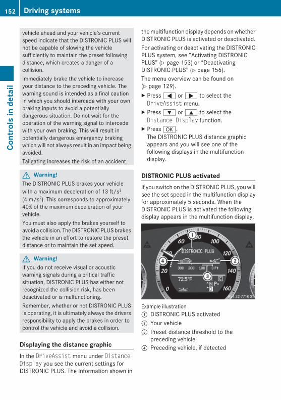
vehicle ahead and your vehicle’s currentspeed indicate that the DISTRONIC PLUS willnot be capable of slowing the vehiclesufficiently to maintain the preset followingdistance, which creates a danger of acollision.Immediately brake the vehicle to increaseyour distance to the preceding vehicle. Thewarning sound is intended as a final cautionin which you should intercede with your ownbraking inputs to avoid a potentiallydangerous situation. Do not wait for theoperation of the warning signal to intercedewith your own braking. This will result inpotentially dangerous emergency brakingwhich will not always result in an impact beingavoided.Tailgating increases the risk of an accident.
G Warning!The DISTRONIC PLUS brakes your vehiclewith a maximum deceleration of 13 ft/s2
(4 m/s2). This corresponds to approximately40% of the maximum deceleration of yourvehicle.You must also apply the brakes yourself toavoid a collision. The DISTRONIC PLUS brakesthe vehicle in an effort to restore the presetdistance or to maintain the set speed.
G Warning!If you do not receive visual or acousticwarning signals during a critical trafficsituation, DISTRONIC PLUS has either notrecognized the collision risk, has beendeactivated or is malfunctioning.Remember, whether or not DISTRONIC PLUSis operating, it is ultimately always the driversresponsibility to apply the brakes in order tocontrol the vehicle and avoid a collision.
Displaying the distance graphicIn the DriveAssist menu under Distance Display you see the current settings forDISTRONIC PLUS. The Information shown in
the multifunction display depends on whetherDISTRONIC PLUS is activated or deactivated.For activating or deactivating the DISTRONICPLUS system, see “Activating DISTRONICPLUS” (Y page 153) or “DeactivatingDISTRONIC PLUS” (Y page 156).The menu overview can be found on(Y page 129).X Press = or ; to select theDriveAssist menu.
X Press : or 9 to select theDistance Display function.
X Press a.The DISTRONIC PLUS distance graphicappears and you will see one of thefollowing displays in the multifunctiondisplay.
DISTRONIC PLUS activatedIf you switch on the DISTRONIC PLUS, you willsee the set speed in the multifunction displayfor approximately 5 seconds. When theDISTRONIC PLUS is activated the followingdisplay appears in the multifunction display.
Example illustration: DISTRONIC PLUS activated; Your vehicle= Preset distance threshold to the
preceding vehicle? Preceding vehicle, if detected
152 Driving systemsCo
ntro
ls in
det
ail
212_AKB; 2; 41, en-USd2ureepe, Version: 2.11.8.1
2009-07-17T09:14:21+02:00 - Seite 152

DISTRONIC PLUS deactivatedWhen the DISTRONIC PLUS is deactivated,you will see the following display in themultifunction display.
Example illustration: Preceding vehicle, if detected; Actual distance to the preceding vehicle= Preset distance threshold to the
preceding vehicle? Your vehicleA PRE-SAFE® Brake activated
DISTRONIC PLUS lever
: Setting current or higher speed; Setting current or lower speed= Deactivating the DISTRONIC PLUS? Activating the DISTRONIC PLUS or
resuming to the last set speedA Setting following distance
Activating DISTRONIC PLUS
G Warning!When the DISTRONIC PLUS is switched on,the vehicle can be braked. You shouldtherefore switch off the DISTRONIC PLUS ifthe vehicle must be towed.
You can activate the DISTRONIC PLUS whenthe vehicle speed is above 20 mph(30 km/h).It is also possible to activate the DISTRONICPLUS when the vehicle speed is below20 mph (30 km/h) and the DISTRONIC PLUShas detected a preceding vehicle.If the DISTRONIC PLUS is activated, one ortwo segments ; (Y page 151) around setspeed = (Y page 151) in the multifunctiondisplay are illuminated.The maximum vehicle speed you can set is120 mph (Canada: 200 km/h).If the DISTRONIC PLUS is not activated afterthe DISTRONIC PLUS lever is pulled indirection of arrow ? (Y page 153), you willsee the message: DISTRONIC PLUS --- mph in the multifunction display.In the following cases you cannot activate theDISTRONIC PLUS:Rwithin 2 minutes after driving off, following
an engine startRif the vehicle is secured with the parking
brakeRif the ESC is switched off or has switched
off due to a malfunctionRwhen the automatic transmission is in park
position P, reverse gear R, or neutralposition NRif the hood is openRif the driver’s door is open and the driver
has not fastened his or her seat beltRif the front passenger or a rear passenger
door is openRif the radar sensors are switched off
(Y page 144)
Driving systems 153
Cont
rols
in d
etai
l
212_AKB; 2; 41, en-USd2ureepe, Version: 2.11.8.1
2009-07-17T09:14:21+02:00 - Seite 153
Z

Switching on while drivingYou can switch on the DISTRONIC PLUS whenthe vehicle speed is above 20 mph(30 km/h).Below 20 mph (30 km/h), you can only switchon the DISTRONIC PLUS if the precedingvehicle has been detected and is shown in themultifunction display. If you no longer see thepreceding vehicle in the multifunction displayand if it is no longer detected because it haschanged lanes, for example, the DISTRONICPLUS switches off and a signal sounds.X Pull the DISTRONIC PLUS lever briefly in
direction of arrow ? to call up the last setspeed, or if no speed is stored, to set andstore the current speed.The DISTRONIC PLUS is switched on.
orX Tap the DISTRONIC PLUS lever up : or
down ; until desired speed is set.The DISTRONIC PLUS is switched on.
X Remove your foot from the acceleratorpedal.Your vehicle adapts its speed to thepreceding vehicle, observing the set speedas a maximum value.
If you do not completely remove your footfrom the accelerator pedal, the messageDISTRONIC PLUS Override appears in themultifunction display. The distance to aslower-driving vehicle will not be set. You willdrive at the speed you dictate by pressing theaccelerator pedal.
Switching on when approaching a stationary vehicleIt is helpful to switch on the DISTRONIC PLUSdisplay in the multifunction display to see thata preceding vehicle is detected(Y page 152). You can only switch on theDISTRONIC PLUS below a speed of 20 mph(30 km/h) when a preceding vehicle isdetected.
If the preceding vehicle is stationary, you canonly switch on the DISTRONIC PLUS if yourvehicle is also at a standstill.X Pull the DISTRONIC PLUS lever briefly in
direction of arrow ?.The DISTRONIC PLUS is switched on.
X Tap the DISTRONIC PLUS lever up : ordown ; until desired speed is set.
You can adjust the set speed using theDISTRONIC PLUS lever and the targetdistance using the distance setting switch onthe DISTRONIC PLUS lever (Y page 157).
i If the DISTRONIC PLUS is switched off,the PRE-SAFE® Brake (Y page 69) will warnof an impending collision if this function hasbeen activated with the instrument clustercontrol system (Y page 137).
Starting offWhen the preceding vehicle starts off:X Remove your foot from the brake pedal.X Pull the DISTRONIC PLUS lever briefly in
direction of arrow ?.orX Briefly step on the accelerator pedal.Your vehicle starts off and adapts its speedto the preceding vehicle.
DrivingIf there is no preceding vehicle, theDISTRONIC PLUS functions like the cruisecontrol (Y page 146).When the DISTRONIC PLUS detects that thepreceding vehicle is driving more slowly, itbrakes the vehicle in order to keep thedistance specified by you.When the DISTRONIC PLUS detects that thepreceding vehicle is driving faster, itaccelerates the vehicle up to the set speed.
G Warning!When you step on the brake pedal, you switchoff the DISTRONIC PLUS except when thevehicle is at a standstill. The DISTRONIC PLUS
154 Driving systemsCo
ntro
ls in
det
ail
212_AKB; 2; 41, en-USd2ureepe, Version: 2.11.8.1
2009-07-17T09:14:21+02:00 - Seite 154

will no longer brake your vehicle. You arealways responsible for maintaining a distancefrom other vehicles, observing road speedsand braking well in advance.
Stopping
G Warning!The braking effect of the DISTRONIC PLUS iscanceled and the vehicle can start to roll ifRthe DISTRONIC PLUS is switched off using
the DISTRONIC PLUS leverRyou accelerateRthe DISTRONIC PLUS system or the power
supply is malfunctioning, e.g. due to batteryfailureRthe electrical components in the engine
compartment or the fuses have beenmanipulatedRthe battery is disconnected
G Warning!Never get out of the vehicle while theDISTRONIC PLUS is switched on!The DISTRONIC PLUS must never be operatedor switched off by passengers or from outsidethe vehicle.The DISTRONIC PLUS is not a substitute forthe parking brake. It must not be used tosecure the vehicle when parking.When you get out of the vehicle or switch offthe engine, deactivate the DISTRONIC PLUSand secure the vehicle from rolling away byengaging the parking brake.
When the DISTRONIC PLUS detects that thepreceding vehicle is stopping, the vehiclebrakes until it also stops. Once the vehicle isat a standstill, it remains stationary, withoutdepressing the brake pedal.Depending on the following distance setusing the distance setting switch on theDISTRONIC PLUS lever (Y page 157), thevehicle will stop adequate away from thepreceding vehicle.
When the DISTRONIC PLUS is activated andthe vehicle is at a standstill, the automatictransmission shifts into park position Pautomatically whenRopening the driver’s door and releasing the
seat beltRturning off the engineRopening the hoodRa system malfunction occursRthe on-board voltage is insufficientThe DISTRONIC PLUS is deactivated.
Setting the current speedX Accelerate or decelerate to the desired
speed.X Briefly lift the DISTRONIC PLUS lever in
direction of arrow : or depress indirection of arrow ; (Y page 153).The current speed is set.
X Remove your foot from the acceleratorpedal.
i If you do not take your foot off of theaccelerator pedal and continue toaccelerate past the set speed, the followingmessage will appear in the multifunctiondisplay:DISTRONIC PLUS OverrideThe distance to a slower moving vehicle infront of you will not be set. Your vehiclespeed will then be determined only by theaccelerator pedal position.
Changing the set speed
G Warning!Keep in mind that it may take a brief momentuntil the vehicle has made the necessaryadjustments.Increase or decrease the set vehicle speed toa value that the prevailing road conditions andlegal speed limits permit. Otherwise, suddenand unexpected acceleration or deceleration
Driving systems 155
Cont
rols
in d
etai
l
212_AKB; 2; 41, en-USd2ureepe, Version: 2.11.8.1
2009-07-17T09:14:21+02:00 - Seite 155
Z
of the vehicle could cause an accident and/or serious injury to you and others.
You can increase or decrease the set speedin 1 mph (Canada: 1 km/h) increments or in5 mph (Canada: 10 km/h) increments.When you use the DISTRONIC PLUS lever todecelerate, the brake system will brake thevehicle automatically if the engine’s brakingpower does not brake the vehicle sufficiently.
Adjustment in 1 mph (Canada: 1 km/h) incrementsi The set speed value is increased or
decreased in 1 mph (Canada: 1 km/h)increments each time you lift or press theDISTRONIC PLUS lever up or down to theresistance point.
X Increasing: Briefly lift the DISTRONICPLUS lever up to the resistance point indirection of arrow :.
X Decreasing: Briefly press the DISTRONICPLUS lever down to the resistance point indirection of arrow ;.
X Release the DISTRONIC PLUS lever.The new speed is set and the vehicle willaccelerate or decelerate.
Adjustment in 5 mph (Canada: 10 km/h) incrementsi The set speed value is increased or
decreased in 5 mph (Canada: 10 km/h)increments each time you lift or press theDISTRONIC PLUS lever up or down past theresistance point.
X Increasing: Briefly lift the DISTRONICPLUS lever up past the resistance point indirection of arrow :.
X Decreasing: Briefly press the DISTRONICPLUS lever down past the resistance pointin direction of arrow ;.
X Release the DISTRONIC PLUS lever.The new speed is set and the vehicle willaccelerate or decelerate. Keep in mind that
it may take a brief moment until the vehiclehas reached the set speed.
Setting stored speed (Resume function)
G Warning!The set speed stored in memory should onlybe set again if prevailing road conditions andlegal speed limits permit. Possibleacceleration or deceleration differencesarising from returning to the preset speedcould cause an accident and/or serious injuryto you and others.
X Briefly pull the DISTRONIC PLUS lever indirection of arrow ? (Y page 153).The DISTRONIC PLUS is activated andresumes to the last set speed or, if nospeed is stored, it will set and store thecurrent speed.
X Remove your foot from the acceleratorpedal.
Deactivating DISTRONIC PLUSX Depress the brake pedal (only possible if
the vehicle is in motion).orX Briefly push the DISTRONIC PLUS lever in
direction of arrow = (Y page 153).The last set speed is stored for later use.
The last stored speed is deleted from memorywhen the engine is turned off.The DISTRONIC PLUS switches offautomatically whenRthe vehicle is secured with the parking
brakeRthe vehicle speed falls below 15 mph
(25 km/h) and no preceding vehicle isdetectedRthe ESC is in operation, or switched off with
the ESC switch (Y page 66), or the ESC hasswitched off due to a malfunction
156 Driving systemsCo
ntro
ls in
det
ail
212_AKB; 2; 41, en-USd2ureepe, Version: 2.11.8.1
2009-07-17T09:14:21+02:00 - Seite 156

Ryou shift the automatic transmission intopark position P, reverse gear R, or neutralposition N while drivingRthe radar sensors are switched offRyou pull the DISTRONIC PLUS lever in
direction of arrow ? (Y page 153) fordriving off and the passenger door is open
The segments indicating the set speed in themultifunction display go out, an acousticsignal sounds, and the message DISTRONIC PLUS Off appears in the multifunctiondisplay for approximately 5 seconds.
G Warning!The DISTRONIC PLUS switches off andreleases the brakes when the vehicledecelerates below the minimum speed of20 mph (30 km/h) by operation of the systemunless the DISTRONIC PLUS detects a vehicledirectly ahead of you. At that time the drivermust apply the brakes in order to reducevehicle speed further or bring it to a stop.
Depressing the accelerator pedal does notdeactivate the DISTRONIC PLUS. After a briefacceleration (e.g. for passing), theDISTRONIC PLUS will resume the last setspeed.
Setting the following distance in DISTRONIC PLUSYou can set the specified following distancefor the DISTRONIC PLUS by varying the timesetting between 1.0 and 2.0 seconds. Usingthis time setting and the current speed ofyour vehicle, the DISTRONIC PLUS calculatesand sets the required following distance tothe preceding vehicle.The set distance will be shown in themultifunction display.
G Warning!It is up to the driver to exercise discretion toselect the appropriate setting given roadconditions, traffic, driver’s preferred driving
style and applicable laws and drivingrecommendations for safe following distance.
X Increasing distance: Turn distancesetting switch : in direction of arrow ;.Increasing the distance setting tells theDISTRONIC PLUS to maintain a greaterfollowing distance to the preceding vehicle.
X Decreasing distance: Turn distancesetting switch : in direction of arrow =.Decreasing the distance setting tells theDISTRONIC PLUS to maintain a shorterfollowing distance to the preceding vehicle.
Driving with DISTRONIC PLUSThis section describes a number of drivingsituations where special precaution isrequired on the part of the driver. Be preparedto brake in such situations. Braking willdeactivate the DISTRONIC PLUS system.
G Warning!The DISTRONIC PLUS works to maintain thespeed selected by the driver unless a movingobstacle proceeding directly ahead of it in thesame travel direction is detected (e.g.following another vehicle ahead of you at yourset distance).This means that:RYour vehicle can pass another vehicle after
you have changed lanes.RWhile in a sharp turn or if the preceding
vehicle is in a sharp turn, the DISTRONIC
Driving systems 157
Cont
rols
in d
etai
l
212_AKB; 2; 41, en-USd2ureepe, Version: 2.11.8.1
2009-07-17T09:14:21+02:00 - Seite 157
Z

PLUS could lose sight of the precedingvehicle. Your vehicle could then accelerateto the previously selected speed.
The DISTRONIC PLUS regulates only thedistance between your vehicle and thosedirectly ahead of it. It may not registerstationary objects in the road, e.g.:Ra stopped vehicle in a traffic jamRa disabled vehicleRan oncoming vehicle
The driver must always be alert, observe alltraffic and intercede as required by means ofsteering or braking the vehicle.
G Warning!The DISTRONIC PLUS should not be used insnowy or icy road conditions.
The most likely cause for a malfunctioningsystem is a dirty sensor (located in the hoodgrille and in the bumper), especially at timesof snow and ice or heavy rain.In such a case, the DISTRONIC PLUS willswitch off, and the message DISTRONIC PLUS Currently Unavailable See Operator's Manual appears in themultifunction display.For cleaning and care of the sensors, see(Y page 263).
i If the message DISTRONIC PLUS Currently Unavailable See Operator's Manual disappears duringdriving and the last speed stored flashes forapproximately 5 seconds, the dirt (e.g.slush) has dissolved; the DISTRONIC PLUSis available again.
Another cause might be that the radarsensors have been manually switched off inthe instrument cluster control system. Pleaseverify that the radar sensors are switched on(Y page 144).
Turns and bends
In turns or bends, the DISTRONIC PLUS maynot detect a preceding vehicle, or it maydetect one too soon. This may cause yourvehicle to brake late or unexpectedly.
Offset driving
A vehicle traveling in your lane but offset fromyour direct line of travel may not be detectedby the DISTRONIC PLUS. There will beinsufficient distance to the preceding vehicle.
Lane changing
158 Driving systemsCo
ntro
ls in
det
ail
212_AKB; 2; 41, en-USd2ureepe, Version: 2.11.8.1
2009-07-17T09:14:21+02:00 - Seite 158

The DISTRONIC PLUS has not yet detectedthe vehicle changing lanes. There will beinsufficient distance to the lane-changingvehicle.
Narrow vehicles
Because of their narrow profile, the vehiclestraveling near the outer edges of the lanehave not yet been detected by the DISTRONICPLUS. There will be insufficient distance tothe preceding vehicles.
Obstacles and stationary vehicles
The DISTRONIC PLUS does not brake forobstacles or stationary vehicles. If, forexample, the vehicle detected in front of youchanges lanes to bypass an obstacle orstationary vehicle in front of it, theDISTRONIC PLUS will not brake for theobstacle or stationary vehicle.
Cross-traffic
The DISTRONIC PLUS may inadvertentlydetect crossing vehicles. If you switch on theDISTRONIC PLUS, for example, at a trafficlight with cross traffic, the vehicle maysuddenly start to drive off.
RACE START (E 63 AMG)RACE START enables optimum accelerationfrom a standing start with suitable high-griproad surface conditions.
G Warning!RACE START is only available when the ESCSPORT mode is switched on. ESC SPORTstabilizes the vehicle only to a limited extentif the vehicle starts to skid or when a wheel isspinning.RACE START should be used only on closedtracks. Always adapt your speed and drivingto the prevailing road and weather conditions.
Conditions for activationRACE START can be activated whenRthe doors are closedRthe engine is running and has reached its
operating temperature of approximately80†. This is the case when the engine oiltemperature indicator in the multifunctiondisplay stops flashing.RESC SPORT is switched on (Y page 67)Rthe multifunction steering wheel is in the
straight-ahead position
Driving systems 159
Cont
rols
in d
etai
l
212_AKB; 2; 41, en-USd2ureepe, Version: 2.11.8.1
2009-07-17T09:14:21+02:00 - Seite 159
Z
Rthe vehicle is standing still and the brakepedal is depressed (left foot)Rthe automatic transmission is in drive
position D
Activating RACE STARTX Depress the brake pedal with your left foot
and keep it depressed.X Turn the program mode selector dial
clockwise (Y page 121) until the RS lampon the dial comes on.The message RACE START Confirm: Paddle UP Cancel: Paddle DOWNappears in the multifunction display.
i When the activation conditions are notfulfilled anymore, RACE START is canceled.The message RACE START Canceledappears in the multifunction display.
X To cancel: Pull left steering wheel gearshiftcontrol (Y page 122).
orX To confirm: Pull right steering wheel
gearshift control (Y page 122).The message RACE START Available Depress gas pedal. appears in themultifunction display.
i If you do not depress the acceleratorpedal within 2 seconds, RACE START iscanceled. The message RACE START Not Possible See Operator’s Manualappears in the multifunction display.
X Depress the accelerator pedal fully.The engine speed rises to approximately4000 rpm.The message RACE START Release brake to start appears in themultifunction display.
i If you do not release the brake pedalwithin 7 seconds, RACE START is canceled.
The message RACE START Canceledappears in the multifunction display.
X Take your foot off the brake pedal whilekeeping the accelerator pedal depressed.The vehicle pulls away at maximumacceleration.The message RACE START Active appearsin the multifunction display.
RACE START deactivates at a vehicle speedof approximately 30 mph(Canada: 50 km/h). The automatictransmission switches to program mode S+.ESC SPORT remains switched on.RACE START is canceled immediately if yourelease the accelerator pedal while RACESTART is active or when the activationconditions are not fulfilled anymore. Themessage RACE START Not Possible See Operator’s Manual appears in themultifunction display.
i If RACE START is used repeatedly in ashort period of time, it is only availableagain after having driven the vehicle acertain distance.
Hill-start assist systemOn uphill grades, the hill-start assist systemmaintains the pressure in the brake systemfor approximately 1 second after you havereleased the brake pedal. Therefore, you canstart off smoothly without the vehicle movingimmediately after releasing the brake pedal.
G Warning!The hill-start assist system is not designed tofunction as a parking brake. It does notprevent the vehicle from moving when parkedon an incline.Always engage the parking brake in additionto shifting the automatic transmission intopark position P.
X Depress the brake pedal.X Shift the automatic transmission into drive
position D or reverse gear R.
160 Driving systemsCo
ntro
ls in
det
ail
212_AKB; 2; 41, en-USd2ureepe, Version: 2.11.8.1
2009-07-17T09:14:21+02:00 - Seite 160
X Release the brake pedal.X Carefully depress the accelerator pedal.The hill-start assist system is inactiveRwhen starting off on a level road or downhill
gradesRwith the automatic transmission in neutral
position NRwith the parking brake engagedRif the ESC has switched off due to a
malfunction
All-wheel drive (4MATIC)In vehicles with all-wheel drive (4MATIC),both axles are powered at all times when thevehicle is being operated. The 4MATICimproves traction in conjunction with the ESC(Y page 65) and the Electronic TractionSystem (ETS/4-ETS) (Y page 65).
G Warning!If a drive wheel is spinning due to insufficienttraction:RWhile driving off, apply as little throttle as
possible.RWhile driving, ease up on the accelerator
pedal.RAdapt your speed and driving style to the
prevailing road conditions.
Failure to observe these guidelines couldcause the vehicle to skid.The 4MATIC cannot prevent accidentsresulting from excessive speed.
! Do not tow with one axle raised. Doing socould damage the transfer case, which isnot covered by the Mercedes-Benz LimitedWarranty. All wheels must be on or off theground. Observe instructions for towing thevehicle with all wheels on the ground.
! Only conduct operational or performancetests on a two-axle dynamometer. If such
tests are necessary, contact an authorizedMercedes-Benz Center. You couldotherwise seriously damage the brakesystem and/or the transfer case which isnot covered by the Mercedes-Benz LimitedWarranty.
i In winter operation, the maximumeffectiveness of the 4MATIC is onlyachieved with winter tires (Y page 252) orsnow chains as required.
HOLD functionThe HOLD function can assist youRwhen driving off, especially on steep slopesRwhen maneuvering on steep slopesRwhen waiting in trafficThe vehicle is kept stationary without thedriver having to depress the brake pedal.Upon depressing the accelerator pedal, thebraking effect is canceled and the HOLDfunction is deactivated.
Activation conditionsYou can activate the HOLD function whenRthe vehicle is stationaryRthe engine is runningRyour seat belt is fastened or the driver’s
door is closedRthe parking brake is releasedRthe hood is closedRthe automatic transmission is in neutral
position N, drive position D, or reverse gearRRthe DISTRONIC PLUS is deactivated
(Y page 156)
Driving systems 161
Cont
rols
in d
etai
l
212_AKB; 2; 41, en-USd2ureepe, Version: 2.11.8.1
2009-07-17T09:14:21+02:00 - Seite 161
Z
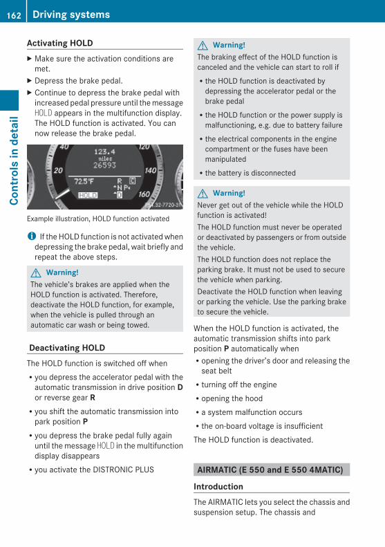
Activating HOLD X Make sure the activation conditions are
met.X Depress the brake pedal.X Continue to depress the brake pedal with
increased pedal pressure until the messageHOLD appears in the multifunction display.The HOLD function is activated. You cannow release the brake pedal.
Example illustration, HOLD function activated
i If the HOLD function is not activated whendepressing the brake pedal, wait briefly andrepeat the above steps.
G Warning!The vehicle’s brakes are applied when theHOLD function is activated. Therefore,deactivate the HOLD function, for example,when the vehicle is pulled through anautomatic car wash or being towed.
Deactivating HOLDThe HOLD function is switched off whenRyou depress the accelerator pedal with the
automatic transmission in drive position Dor reverse gear RRyou shift the automatic transmission into
park position PRyou depress the brake pedal fully again
until the message HOLD in the multifunctiondisplay disappearsRyou activate the DISTRONIC PLUS
G Warning!The braking effect of the HOLD function iscanceled and the vehicle can start to roll ifRthe HOLD function is deactivated by
depressing the accelerator pedal or thebrake pedalRthe HOLD function or the power supply is
malfunctioning, e.g. due to battery failureRthe electrical components in the engine
compartment or the fuses have beenmanipulatedRthe battery is disconnected
G Warning!Never get out of the vehicle while the HOLDfunction is activated!The HOLD function must never be operatedor deactivated by passengers or from outsidethe vehicle.The HOLD function does not replace theparking brake. It must not be used to securethe vehicle when parking.Deactivate the HOLD function when leavingor parking the vehicle. Use the parking braketo secure the vehicle.
When the HOLD function is activated, theautomatic transmission shifts into parkposition P automatically whenRopening the driver’s door and releasing the
seat beltRturning off the engineRopening the hoodRa system malfunction occursRthe on-board voltage is insufficientThe HOLD function is deactivated.
AIRMATIC (E 550 and E 550 4MATIC)
IntroductionThe AIRMATIC lets you select the chassis andsuspension setup. The chassis and
162 Driving systemsCo
ntro
ls in
det
ail
212_AKB; 2; 41, en-USd2ureepe, Version: 2.11.8.1
2009-07-17T09:14:21+02:00 - Seite 162
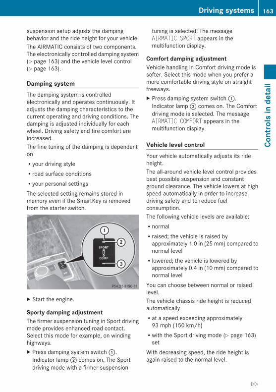
suspension setup adjusts the dampingbehavior and the ride height for your vehicle.The AIRMATIC consists of two components.The electronically controlled damping system(Y page 163) and the vehicle level control(Y page 163).
Damping systemThe damping system is controlledelectronically and operates continuously. Itadjusts the damping characteristics to thecurrent operating and driving conditions. Thedamping is adjusted individually for eachwheel. Driving safety and tire comfort areincreased.The fine tuning of the damping is dependentonRyour driving styleRroad surface conditionsRyour personal settingsThe selected setting remains stored inmemory even if the SmartKey is removedfrom the starter switch.
X Start the engine.
Sporty damping adjustmentThe firmer suspension tuning in Sport drivingmode provides enhanced road contact.Select this mode for example, on windinghighways.X Press damping system switch :.
Indicator lamp ; comes on. The Sportdriving mode with a firmer suspension
tuning is selected. The messageAIRMATIC SPORT appears in themultifunction display.
Comfort damping adjustmentVehicle handling in Comfort driving mode issofter. Select this mode when you prefer amore comfortable driving style on straightfreeways.X Press damping system switch :.
Indicator lamp = comes on. The Comfortdriving mode is selected. The messageAIRMATIC COMFORT appears in themultifunction display.
Vehicle level controlYour vehicle automatically adjusts its rideheight.The all-around vehicle level control providesbest possible suspension and constantground clearance. The vehicle lowers at highspeed automatically in order to increasedriving safety and to reduce fuelconsumption.The following vehicle levels are available:RnormalRraised; the vehicle is raised by
approximately 1.0 in (25 mm) compared tonormal levelRlowered; the vehicle is lowered by
approximately 0.4 in (10 mm) compared tonormal level
You can choose between normal or raisedlevel.The vehicle chassis ride height is reducedautomaticallyRat a speed exceeding approximately
93 mph (150 km/h)Rwith the Sport driving mode (Y page 163)
setWith decreasing speed, the ride height isagain raised to the normal level.
Driving systems 163
Cont
rols
in d
etai
l
212_AKB; 2; 41, en-USd2ureepe, Version: 2.11.8.1
2009-07-17T09:14:21+02:00 - Seite 163
Z
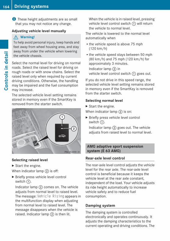
i These height adjustments are so smallthat you may not notice any change.
Adjusting vehicle level manuallyG Warning!To help avoid personal injury, keep hands andfeet away from wheel housing area, and stayaway from under the vehicle when loweringthe vehicle chassis.
Select the normal level for driving on normalroads. Select the raised level for driving onrough roads or with snow chains. Select theraised level only when required by currentdriving conditions. Otherwise, the handlingmay be impaired and the fuel consumptionmay increase.The selected vehicle level setting remainsstored in memory even if the SmartKey isremoved from the starter switch.
Selecting raised levelX Start the engine.When indicator lamp ; is off:X Briefly press vehicle level control
switch :.Indicator lamp ; comes on. The vehicleadjusts from normal level to raised level.The message: Vehicle Rising appears inthe multifunction display when adjustingfrom normal level to raised level. Themessage disappears when the vehicle israised. Indicator lamp ; is then lit.
When the vehicle is in raised level, pressingvehicle level control switch : will returnthe vehicle to normal level.
The vehicle is lowered to the normal levelautomatically whenRthe vehicle speed is above 75 mph
(120 km/h)Rthe vehicle speed stays between 50 mph
(80 km/h) and 75 mph (120 km/h) forapproximately 3 minutes.Indicator lamp ; invehicle level control switch : goes out.
If you do not drive in this speed range, theselected vehicle level setting remains storedin memory even if the SmartKey is removedfrom the starter switch.
Selecting normal levelX Start the engine.When indicator lamp ; is on:X Briefly press vehicle level control
switch :.Indicator lamp ; goes out. The vehicleadjusts from raised level to normal level.
AMG adaptive sport suspension system (E 63 AMG)
Rear-axle level controlThe rear-axle level control adjusts the vehiclelevel for the rear axle. The rear-axle levelcontrol is beneficial because it keeps thevehicle level at the rear axle constant,independent of the load. Your vehicle adjustsits ride height automatically to increasevehicle safety and to reduce fuelconsumption.
Damping systemThe damping system is controlledelectronically and operates continuously. Itadjusts the damping characteristics to thecurrent operating and driving conditions. The
164 Driving systemsCo
ntro
ls in
det
ail
212_AKB; 2; 41, en-USd2ureepe, Version: 2.11.8.1
2009-07-17T09:14:21+02:00 - Seite 164
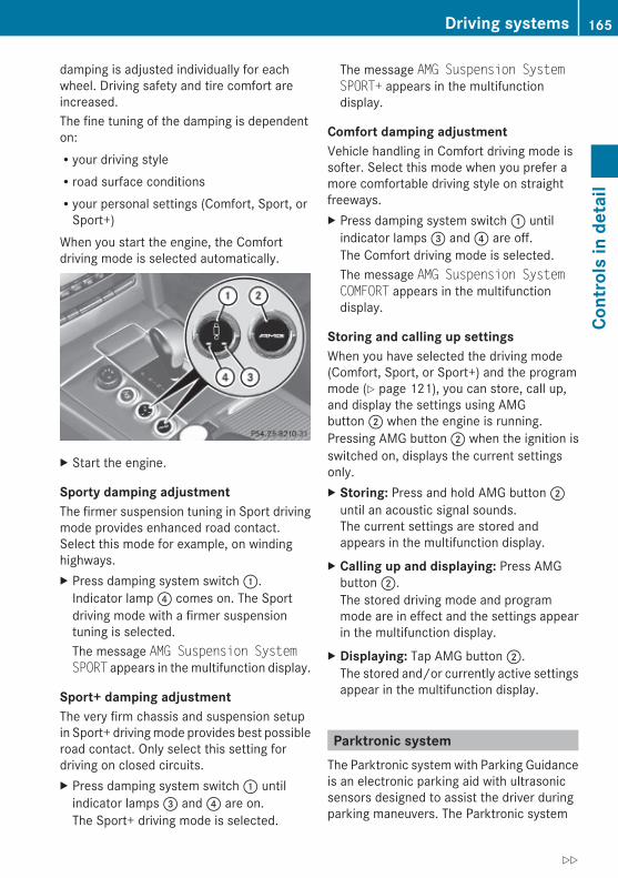
damping is adjusted individually for eachwheel. Driving safety and tire comfort areincreased.The fine tuning of the damping is dependenton:Ryour driving styleRroad surface conditionsRyour personal settings (Comfort, Sport, or
Sport+)When you start the engine, the Comfortdriving mode is selected automatically.
X Start the engine.
Sporty damping adjustmentThe firmer suspension tuning in Sport drivingmode provides enhanced road contact.Select this mode for example, on windinghighways.X Press damping system switch :.
Indicator lamp ? comes on. The Sportdriving mode with a firmer suspensiontuning is selected.The message AMG Suspension System SPORT appears in the multifunction display.
Sport+ damping adjustmentThe very firm chassis and suspension setupin Sport+ driving mode provides best possibleroad contact. Only select this setting fordriving on closed circuits.X Press damping system switch : until
indicator lamps = and ? are on.The Sport+ driving mode is selected.
The message AMG Suspension System SPORT+ appears in the multifunctiondisplay.
Comfort damping adjustmentVehicle handling in Comfort driving mode issofter. Select this mode when you prefer amore comfortable driving style on straightfreeways.X Press damping system switch : until
indicator lamps = and ? are off.The Comfort driving mode is selected.The message AMG Suspension System COMFORT appears in the multifunctiondisplay.
Storing and calling up settingsWhen you have selected the driving mode(Comfort, Sport, or Sport+) and the programmode (Y page 121), you can store, call up,and display the settings using AMGbutton ; when the engine is running.Pressing AMG button ; when the ignition isswitched on, displays the current settingsonly.X Storing: Press and hold AMG button ;
until an acoustic signal sounds.The current settings are stored andappears in the multifunction display.
X Calling up and displaying: Press AMGbutton ;.The stored driving mode and programmode are in effect and the settings appearin the multifunction display.
X Displaying: Tap AMG button ;.The stored and/or currently active settingsappear in the multifunction display.
Parktronic systemThe Parktronic system with Parking Guidanceis an electronic parking aid with ultrasonicsensors designed to assist the driver duringparking maneuvers. The Parktronic system
Driving systems 165
Cont
rols
in d
etai
l
212_AKB; 2; 41, en-USd2ureepe, Version: 2.11.8.1
2009-07-17T09:14:21+02:00 - Seite 165
Z

indicates the relative distance between thevehicle and an obstacle visually and audibly.The Parktronic system is activatedautomatically whenRyou switch on the ignition
andRyou release the parking brake
andRthe automatic transmission is in drive
position D, reverse gear R, or neutralposition N
The Parktronic system deactivates at speedsabove approximately 11 mph (18 km/h). Atlower speeds, the Parktronic systemactivates again.The Parktronic system also deactivates whenyou shift the automatic transmission intopark position P or engage the parking brake.The Parktronic system monitors thesurroundings of your vehicle with six sensorsin the front bumper and four sensors in therear bumper.
Example illustration, sensors in the front bumper
To function properly, sensors : must be freeof dirt, ice, snow and slush. Cleansensors : regularly. Be careful not toscratch or damage sensors :, see “Cleaningthe driving systems sensors” (Y page 263).
G Warning!The Parktronic is a supplemental system. It isnot intended to, nor does it replace, the needfor extreme care. The responsibility during
parking and other critical maneuvers alwaysremains with the driver.
G Warning!Make sure no persons or animals are in ornear the area in which you are parking/maneuvering. Otherwise, they could beinjured.
! Special attention must be paid to objectswith smooth surfaces or low silhouettes(e.g. trailer couplings, painted posts,elevated crossbars or road curbs). Suchobjects may not be detected by the systemand can damage the vehicle.During parking maneuvers, pay specialattention to objects located above or belowthe height of the sensors (e.g. street curbs,painted posts, or trailer hitches etc.). TheParktronic system will not detect suchobjects at close range and damage to yourvehicle or the object may result.
! Ultrasonic signals from outside sources(e.g. truck air brakes, car wash, orjackhammers) may impair the operation ofthe Parktronic system.
Range of the sensors
166 Driving systemsCo
ntro
ls in
det
ail
212_AKB; 2; 41, en-USd2ureepe, Version: 2.11.8.1
2009-07-17T09:14:21+02:00 - Seite 166

Front sensors
Center approx. 40 in (100 cm)
Corners approx. 24 in (60 cm)
Rear sensors
Center approx. 48 in (120 cm)
Corners approx. 32 in (80 cm)
Minimum distance
Center approx. 8 in (20 cm)
Corners approx. 6 in (15 cm)
If the Parktronic system detects an obstaclein this range, all the distance warningsegments illuminate and you hear a warningsignal. If the obstacle is closer than theminimum distance, the actual distance mayno longer be indicated by the Parktronicsystem.
Warning indicators Visual signals indicate the relative distancebetween the sensors and an obstacle.
Front area warning indicators
Rear area warning indicators
Each warning indicator is divided into fiveyellow and two red distance segments for leftside : and right side ; of the vehicle. TheParktronic system is ready to measure whenthe yellow readiness indicators = areilluminated.The current transmission position determineswhich warning indicator will be activated.
Currenttransmissionposition
Warning indicator
D Front area activated
R or N Front and rear areaactivated
As your vehicle approaches an object, one ormore distance segments will illuminate,depending on the distance. When the seventhdistance segment illuminates, you havereached the minimum distance.
Driving systems 167
Cont
rols
in d
etai
l
212_AKB; 2; 41, en-USd2ureepe, Version: 2.11.8.1
2009-07-17T09:14:21+02:00 - Seite 167
Z

RFront area: An intermittent acousticwarning will sound as the first red distancesegment illuminates and a constantacoustic warning lasting a maximum of2 seconds will sound for the second reddistance segment. The signal is canceledwhen the automatic transmission is shiftedinto park position P or the parking brake isengaged.RRear area: An intermittent acoustic
warning will sound as the first red distancesegment illuminates and a constantacoustic warning lasting a maximum of2 seconds will sound for the second reddistance segment. The signal is canceledwhen the automatic transmission is shiftedinto drive position D, or park position P, orthe parking brake is engaged.
Switching the Parktronic system on/off The Parktronic system switches onautomatically when the ignition is switchedon.
X Switching off: Press Parktronicswitch :.Indicator lamp ; comes on.
X Switching on: Press Parktronic switch :again.
i When you switch the Parktronic systemon or off the Parking Guidance(Y page 168) is also switched on or off.
Parktronic system malfunction There is a malfunction in the Parktronicsystem, if only the red distance segmentsilluminate and an acoustic warning sounds.The Parktronic system will switch offautomatically after 20 seconds and indicatorlamp ; in Parktronic switch : comes on.X Have the Parktronic system checked at an
authorized Mercedes-Benz Center as soonas possible.
If only the red distance segments illuminateand no acoustic warning sounds, theParktronic system sensors are dirty (e.g. dirt,ice, snow and slush). Another cause could beinterference from other radio or ultrasonicsignals (e.g. truck air brakes, car wash, orjackhammers). The Parktronic system willswitch off automatically after 20 seconds andindicator lamp ; in Parktronic switch :comes on.X Switch off the ignition.X Clean the Parktronic system sensors
(Y page 263).X Switch on the ignition.
orX Check the Parktronic system operation at
another location to rule out interferencefrom outside radio or ultrasonic signals.
Parking GuidanceThe Parking Guidance is part of the Parktronicsystem. With the Parktronic system switchedon (Y page 168), the Parking Guidance is alsoavailable.The Parking Guidance is an electronic parkingaid equipped with ultrasonic sensors. Theultrasonic sensors scan the area on bothsides of vehicle. When a suitable parkingspace is found, it is indicated by a parkingspace symbol in the multifunction display.You will receive steering instructions forparking in that space.
168 Driving systemsCo
ntro
ls in
det
ail
212_AKB; 2; 41, en-USd2ureepe, Version: 2.11.8.1
2009-07-17T09:14:21+02:00 - Seite 168

G Warning!The Parking Guidance is only an aid and maydisplay parking spaces that are not suitablefor parking such asRno-parking zonesRparking space with unsuitable road/ground
surfaceRdrivewaysRentrances/exits
The Parking Guidance scans for and measurespotential parking spaces when driving past.Subsequent changes to the parking space arenot taken into account. This may be the caseif the position of the vehicle parked in front orbehind the space changes or obstacles in theparking space are moved.The Parking Guidance does not relieve you ofthe responsibility to pay attention. If you onlyrely on the Parking Guidance, you may causean accident and injure yourself and others.You are always responsible for safety andmust continue to pay attention to yourimmediate surroundings when parking andmaneuvering.
G Warning!The system cannot detect objects locatedabove the area that the sensors scan. Theseobjects, e.g. protruding load, overhang, ortruck tail lifts, will be ignored when computingthe parking procedure. The Parking Guidancemight therefore provide untimely steeringinstructions. This could cause a collision.Thus, do not use the Parking Guidance in suchsituations.
G Warning!Make sure no persons or animals are in thearea in which you are maneuvering. You couldotherwise injure them.
! Special attention must be paid to objectswith smooth surfaces or low silhouettes(e.g. trailer couplings, painted posts,elevated crossbars or road curbs). Such
objects may not be detected by the systemand can damage the vehicle.
Use the Parking Guidance for parking spacesthat areRparallel to the direction of travelRlocated on straight streets, i.e. not in
curvesRon the same level as the street, i.e. not on
sidewalks, for example.Parking instructions:ROn narrow streets, drive by the parking
space as close as possible.RParking spaces that are dirty, overgrown or
located in front of trailers may not bedetected correctly.RSnowfall or heavy rain may cause imprecise
measurement of the parking space.RAlso observe the Parktronic system
warning indicator (Y page 167) while theParking Guidance is active.RYou may not use the Parking Guidance
when transporting cargo that protrudes thevehicle.RDo not use the Parking Guidance when
driving with snow chains or when a sparewheel is mounted.RHow well your vehicle will be parked after
completion of the Parking Guidancedepends on the position and shape of thevehicles parked in front of and behind theparking space as well as the conditions ofthe immediate surroundings. In certaincases, the Parking Guidance may guide youtoo far into the parking space or not farenough. If this is the case, cancel theparking procedure with the ParkingGuidance and correct the vehicle positionyourself.
Detecting a parking spaceThe Parking Guidance is active when drivingforward. The system operates at a vehicle
Driving systems 169
Cont
rols
in d
etai
l
212_AKB; 2; 41, en-USd2ureepe, Version: 2.11.8.1
2009-07-17T09:14:21+02:00 - Seite 169
Z

speed of up to 22 mph (35 km/h). It scansautomatically for and measures potentialparking spaces on both sides of the vehicle.
Example illustration: Detected parking space on the left; Parking space symbol= Detected parking space on the right
At a vehicle speed of below 19 mph(30 km/h), you see parking spacesymbol ; as a system display in themultifunction display.When a parking space has been detected, anadditional arrow to the right = or to theleft : appears.In order to be detected by the ParkingGuidance, a parking space must beRparallel to the direction of travelRat least 5 ft (1.5 m) wideRat least 4.3 ft (1.3 m) longer than your
vehicle isA parking space is shown in the multifunctiondisplay when driving by until you havereached a distance of 50 ft (15 m) from thespace. The Parking Guidance only showsparking spaces on the passenger side of thevehicle unless you activate the driver’s side(left) turn signal. If you would like to park onthe driver’s side, the left turn signal mustremain on until the reverse gear is engaged.
Parking
G Warning!The Parking Guidance is only an aid and maynot detect all obstacles. The ParkingGuidance does not relieve you of theresponsibility to pay attention. You are always
responsible for safety and must continue topay attention to your immediate surroundingswhen parking and maneuvering. Otherwise,you could endanger yourself and others.
X Bring the vehicle to a standstill as long asthe desired parking space is displayed bythe parking space symbol in themultifunction display.
X Shift the automatic transmission intoreverse gear R.The message Check Vehicle Surroundings Press ’OK’ to Confirmappears in the multifunction display.
X Press a on the multifunction steeringwheel to confirm.The display in the multifunction displaychanges to the Parking Guidance.The message Please Drive Backwardappears in the multifunction display,depending on the distance to the parkingspace.
Example illustration
X If applicable, drive straight backward alittle.An arrow pointing toward you indicates thebackward direction.
X Drive straight backward until an acousticsignal sounds. Stop the vehicle. You havereached the stop position. The arrow iscompletely white.The message Please Steer Wheel to the Right or Please Steer Wheel to the Left appears in the multifunctiondisplay.
170 Driving systemsCo
ntro
ls in
det
ail
212_AKB; 2; 41, en-USd2ureepe, Version: 2.11.8.1
2009-07-17T09:14:21+02:00 - Seite 170
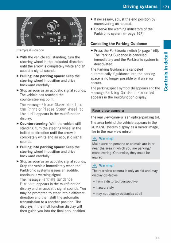
Example illustration
X With the vehicle still standing, turn thesteering wheel in the indicated directionuntil the arrow is completely white and anacoustic signal sounds.
X Pulling into parking space: Keep thesteering wheel in position and drivebackward carefully.
X Stop as soon as an acoustic signal sounds.The vehicle has reached thecountersteering point.The message Please Steer Wheel to the Right or Please Steer Wheel to the Left appears in the multifunctiondisplay.
X Countersteering: With the vehicle stillstanding, turn the steering wheel in theindicated direction until the arrow iscompletely white and an acoustic signalsounds.
X Pulling into parking space: Keep thesteering wheel in position and drivebackward carefully.
X Stop as soon as an acoustic signal sounds.Stop the vehicle immediately when theParktronic systems issues an audible,continuous warning signal.The message Parking Guidance Finished appears in the multifunctiondisplay and an acoustic signal sounds. Youmay be prompted to steer into a differentdirection and then shift the automatictransmission to a another position. Thedisplays in the multifunction display willthen guide you into the final park position.
X If necessary, adjust the end position bymaneuvering as needed.
X Observe the warning indicators of theParktronic system (Y page 167).
Canceling the Parking Guidance X Press the Parktronic switch (Y page 168).
The Parking Guidance is canceledimmediately and the Parktronic system isdeactivated.
The Parking Guidance is canceledautomatically if guidance into the parkingspace is no longer possible or if an erroroccurs.The parking space symbol disappears and themessage Parking Guidance Canceledappears in the multifunction display.
Rear view cameraThe rear view camera is an optical parking aid.The area behind the vehicle appears in theCOMAND system display as a mirror image,like in the rear view mirror.
G Warning!Make sure no persons or animals are in ornear the area in which you are parking/maneuvering. Otherwise, they could beinjured.
G Warning!The rear view camera is only an aid and maydisplay obstaclesRfrom a distorted perspectiveRinaccuratelyRmay not display obstacles at all
Driving systems 171
Cont
rols
in d
etai
l
212_AKB; 2; 41, en-USd2ureepe, Version: 2.11.8.1
2009-07-17T09:14:21+02:00 - Seite 171
Z
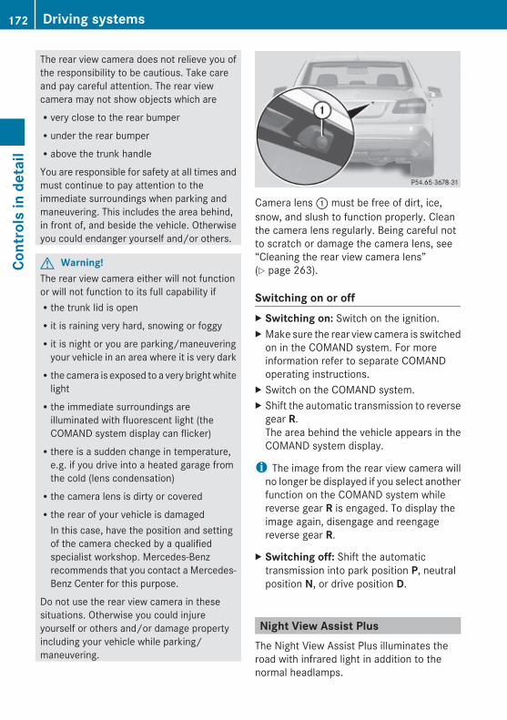
The rear view camera does not relieve you ofthe responsibility to be cautious. Take careand pay careful attention. The rear viewcamera may not show objects which areRvery close to the rear bumperRunder the rear bumperRabove the trunk handle
You are responsible for safety at all times andmust continue to pay attention to theimmediate surroundings when parking andmaneuvering. This includes the area behind,in front of, and beside the vehicle. Otherwiseyou could endanger yourself and/or others.
G Warning!The rear view camera either will not functionor will not function to its full capability ifRthe trunk lid is openRit is raining very hard, snowing or foggyRit is night or you are parking/maneuvering
your vehicle in an area where it is very darkRthe camera is exposed to a very bright white
lightRthe immediate surroundings are
illuminated with fluorescent light (theCOMAND system display can flicker)Rthere is a sudden change in temperature,
e.g. if you drive into a heated garage fromthe cold (lens condensation)Rthe camera lens is dirty or coveredRthe rear of your vehicle is damaged
In this case, have the position and settingof the camera checked by a qualifiedspecialist workshop. Mercedes-Benzrecommends that you contact a Mercedes-Benz Center for this purpose.
Do not use the rear view camera in thesesituations. Otherwise you could injureyourself or others and/or damage propertyincluding your vehicle while parking/maneuvering.
Camera lens : must be free of dirt, ice,snow, and slush to function properly. Cleanthe camera lens regularly. Being careful notto scratch or damage the camera lens, see“Cleaning the rear view camera lens”(Y page 263).
Switching on or offX Switching on: Switch on the ignition.X Make sure the rear view camera is switched
on in the COMAND system. For moreinformation refer to separate COMANDoperating instructions.
X Switch on the COMAND system.X Shift the automatic transmission to reverse
gear R.The area behind the vehicle appears in theCOMAND system display.
i The image from the rear view camera willno longer be displayed if you select anotherfunction on the COMAND system whilereverse gear R is engaged. To display theimage again, disengage and reengagereverse gear R.
X Switching off: Shift the automatictransmission into park position P, neutralposition N, or drive position D.
Night View Assist PlusThe Night View Assist Plus illuminates theroad with infrared light in addition to thenormal headlamps.
172 Driving systemsCo
ntro
ls in
det
ail
212_AKB; 2; 41, en-USd2ureepe, Version: 2.11.8.1
2009-07-17T09:14:21+02:00 - Seite 172

A camera at the top of the windshieldmeasures the infrared light and shows ablack-and-white image in the COMANDsystem display. The image in the COMANDsystem display corresponds to a road lit upby high-beam headlamps.
G Warning!The Night View Assist Plus is only an aid tosupport you while driving and cannotsubstitute your careful attention. Do not relyon the display of the Night View Assist Plus;instead, continue to look through thewindshield. You are always responsible forsafety and must drive in accordance withtraffic conditions. Otherwise, you couldendanger yourself and others.The system may be impaired or unavailablewhenRvisibility is poor, e.g. due to snow, rain, fog,
or heavy sprayRthe camera area of the windshield is dirty,
fogged up or covered by a sticker forexampleRdriving through curves or on inclines or
declines
G Warning!The Night View Assist Plus cannot recordobjects immediately in front of or next to thevehicle. When maneuvering, continue to lookthrough the windshield. Make sure nopersons or animals are in the area in whichyou are maneuvering. You could otherwiseinjure them.
The Night View Assist Plus image in theCOMAND system display is not impaired bythe headlamps of approaching vehicles.As a result, you can better follow the courseof the road and detect obstacles earlier on.
i Infrared light is invisible to the human eyeand thus does not blind. The Night ViewAssist Plus can remain switched onpermanently even with oncoming trafficpresent.
The Night View Assist Plus monitors the areain front of your vehicle via camera :.
Switching on or offYou can only switch on the Night View AssistPlus ifRthe SmartKey in the starter switch is set to
position 2Rit is darkRthe exterior lamp switch is set to c orL
Rthe automatic transmission is not inreverse gear R
X Switch on the COMAND system.X Press button :.
The Night View Assist Plus image appearsin the COMAND system display.
For information on how to adjust thebrightness of the COMAND system display,refer to the separate COMAND systemoperating instructions.
Driving systems 173
Cont
rols
in d
etai
l
212_AKB; 2; 41, en-USd2ureepe, Version: 2.11.8.1
2009-07-17T09:14:21+02:00 - Seite 173
Z

i The infrared headlamps only come onabove a speed of approximately 6 mph(10 km/h). Therefore, when you are at astandstill, you do not have a complete viewand cannot check the function of the NightView Assist Plus.
Pedestrian detectionThe Night View Assist Plus detectspedestrians by means of specificcharacteristics, e.g. a human silhouette.Pedestrian detection is activated whenRthe Night View Assist Plus is switched onRthe vehicle speed is above approximately
6 mph (10 km/h)Rdriving in darkness, e.g. on highways
without road lighting
: Night View Assist Plus image; Detected pedestrian= Frame? Symbol for active pedestrian detection
When pedestrian detection is active,symbol ? appears in the Night View AssistPlus image. Once a pedestrian is detected,that pedestrian is highlighted by frame =.When you have been made aware of apedestrian, assess the situation by lookingthrough the windshield. The actual distancebetween your vehicle and objects orpedestrians cannot be assessed properly viaa screen display.Other objects apart from pedestrians mayalso be highlighted.
G Warning!The pedestrian detection may be impaired orunavailable whenRpedestrians are obstructed fully or in part
by other objects such as parking vehiclesRthe silhouette in the Night View Assist Plus
image is displayed incomplete orinterrupted, e.g. by significant lightreflectionRa pedestrian’s silhouette is not rich enough
in contrast compared to the backgroundRpedestrians are not in erected position but,
for example, sit, crouch down, or lie
i Animals cannot be detected.
Dirty or fogged-up windshieldThe Night View Assist Plus image isdiminished when the windshield in front of thecamera isRdirtyRfogged up on the outsideRfogged up on the inside
G Warning!Please do not forget that your primaryresponsibility is to drive the vehicle. A driver’sattention to the road must always be his/herprimary focus when driving. For your safetyand the safety of others, stop before trying toremove window fogging or cleaning thewindshield in front of the Night View AssistPlus camera.Bear in mind that at a speed of just 30 mph(approximately 50 km/h), your vehicle iscovering a distance of 44 feet(approximately 14 m) every second.
X Removing condensation: Check settingsof the climate control and change them, ifnecessary (Y page 181).
X Swing the camera cover downward(Y page 263).
174 Driving systemsCo
ntro
ls in
det
ail
212_AKB; 2; 41, en-USd2ureepe, Version: 2.11.8.1
2009-07-17T09:14:21+02:00 - Seite 174

X Cleaning inside of windshield: Use a soft,non-scratching cloth (Y page 263).
Blind Spot AssistThe Blind Spot Assist uses radar sensors tomonitor the area on both sides of yourvehicle. It will assist you when you changelanes driving at speeds of above 20 mph(30 km/h). A red warning lamp will come onin the exterior rear view mirror as soon asanother vehicle is detected. If you thenactivate the corresponding turn signals tochange lanes, the red warning lamp flashesand warning sounds (collision warning). TheBlind Spot Assist operates using sensors inthe rear bumper.
G Warning!The Blind Spot Assist is only a driving aid andmay not detect all vehicles.The Blind Spot Assist may not be able todetect narrow vehicles such as motorcyclesor bicycles, or it may not detect them until itis too late.The monitoring function may be impaired ifyour sensors are dirty, subject to heavy spray,or if visibility is poor due to e.g. snow, rain, orfog. This can result in vehicles not beingdetected or being detected too late.The Blind Spot Assist cannot detect road,traffic and weather conditions.It is the driver’s responsibility at all times tobe attentive to road, weather and trafficconditions and to provide the steering,braking and other driving inputs necessary toretain control of the vehicle. Failure to do socould result in recognizing dangers too late,possibly resulting in an accident and seriousinjury to yourself and others.
In order for the Blind Spot Assist to function,the radar sensors must be switched on andoperational.When traveling in Canada in a vehicle notregistered in Canada, you must switch off theradar sensor system (Y page 144). Canadian
law does not permit the use of the radarsensor system for vehicles from outside ofCanada. When you switch off the radar sensorsystem, the following functions aredeactivated:RBlind Spot AssistRBAS PLUS (Y page 63)RPRE-SAFE® Brake (Y page 69)RDISTRONIC PLUS (Y page 149)
i USA only:This device has been approved by the FCCas a “Vehicular Radar System”. The radarsensor is intended for use in an automotiveradar system only. Removal, tampering, oraltering of the device will void anywarranties, and is not permitted by theFCC. Do not tamper with, alter, or use inany non-approved way.Any unauthorized modification to thisdevice could void the user’s authority tooperate the equipment.
i Canada only:This device complies with RSS-210 ofIndustry Canada. Operation is subject tothe following two conditions:1. This device may not cause interference,
and2. this device must accept any
interference received, includinginterference that may cause undesiredoperation of the device.
Removal, tampering, or altering of thedevice will void any warranties, and is notpermitted. Do not tamper with, alter, or usein any non-approved way.Any unauthorized modification to thisdevice could void the user’s authority tooperate the equipment.
Sensor monitoring rangeThe Blind Spot Assist is able to monitor arange up to 10 ft (3 m) to the rear and bothsides of the vehicle.
Driving systems 175
Cont
rols
in d
etai
l
212_AKB; 2; 41, en-USd2ureepe, Version: 2.11.8.1
2009-07-17T09:14:21+02:00 - Seite 175
Z

G Warning!The Blind Spot Assist monitors certain areasin the immediate vicinity of your vehicle.Vehicles approaching and passing at speedsthat exceed the speed of your vehiclesignificantly will not be detected. There will beno warning display and no audible warning.When driving in a very wide lane, the sensorsmay not be able to cover the entire width ofthe neighboring lane. Vehicles driving on theoutside of the neighboring lane may not bedetected.It is the driver’s responsibility at all times tobe attentive to road, weather and trafficconditions and to provide the steering,braking and other driving inputs necessary toretain control of the vehicle. Failure to do socould result in recognizing dangers too late,possibly resulting in an accident and seriousinjury to yourself and others.When driving in a very narrow lane, thesensors may detect and display vehicles in thesecond lane over. This will be the case if thereare vehicles driving on the inside edge of theirlane.The system may issue causeless warnings inthe area of guardrails or similar structuralboundaries.
The two Blind Spot Assist sensors are builtinto the rear bumper. Make sure that the area
of the bumper around the sensors is free ofdirt, ice and snow. The radar sensors must notbe obstructed, for example, by bicyclecarriers or overhanging luggage.
! In the event of a significant impact ordamage affecting the bumpers, have theradar sensors checked by a qualifiedspecialist workshop such as a Mercedes-Benz Center. Failure to do this can result inBlind Spot Assist not functioning correctly.
Indicator and warning lamps
Exterior rear view mirror, driver’s side
X Make sure that the radar sensors(Y page 144) and Blind Spot Assist(Y page 138) are switched on.
X Switch on the ignition.Red warning lamps : in the exterior rearview mirrors come on.
X Start the engine.Yellow indicator lamps : in the exteriorrear view mirrors come on up to a speed of20 mph (30 km/h).
Above a speed of 20 mph (30 km/h), yellowindicator lamps : go out and the Blind SpotAssist is active. If the Blind Spot Assistdetects a vehicle in its range, red warninglamp : on the corresponding side of thevehicle comes on. The warning is issued eachtime a vehicle enters the area monitored bythe Blind Spot Assist from behind or from theside. When you pass another vehicle, thewarning is issued only when the speeddifferential is less than 7 mph (12 km/h).
176 Driving systemsCo
ntro
ls in
det
ail
212_AKB; 2; 41, en-USd2ureepe, Version: 2.11.8.1
2009-07-17T09:14:21+02:00 - Seite 176

When you shift the automatic transmission inreverse gear R, yellow indicator lamps : inthe exterior rear view mirrors goes out afterapproximately 3 seconds. The Blind SpotAssist is then not active.The brightness of indicator lamps/warninglamps : is controlled automaticallydepending on the brightness of the ambientlight.
G Warning!The Blind Spot Assist is not active at speedsbelow approximately 20 mph (30 km/h). Theyellow indicator lamps in the exterior rearview mirrors are illuminated. You will not bealerted to the presence of vehicles in themonitored area at these speeds.It is the driver’s responsibility at all times tobe attentive to road, weather and trafficconditions and to provide the steering,braking and other driving inputs necessary toretain control of the vehicle. Failure to do socould result in recognizing dangers too late,possibly resulting in an accident and seriousinjury to yourself and others.
Collision warningIf a vehicle is detected in the Blind Spot Assistrange and you activate the turn signal, a two-tone warning will sound once. Red warninglamp : on the corresponding side of thevehicle will flash.
G Warning!Do not change lanes or make turns, while redwarning lamp : is flashing. Doing so couldresult in an accident and serious injury toyourself and others.
X Remain on the lane that you are currentlyon until traffic conditions permit to change.
If the turn signal remains on, red warninglamp : will flash to indicate that vehicleshave been detected. No further audiblewarnings will sound.
Lane Keeping AssistThe Lane Keeping Assist supports you at avehicle speed of above 40 mph when youhave set the display unit to miles in theDisplay Unit Speed-/Odometer: menu inthe control system (Y page 141). When youhave set the display unit to km, the systemsupports you at a vehicle speed of above60 km/h. When the Lane Keeping Assistdetects lane markings, the system isdesigned to alert you in case you leave yourlane unintentionally. A warning is usuallyissued when a front wheel is on the lanemarking. An interval vibration in the steeringwheel that lasts for up to 1.5 seconds willthen alert you.
The Lane Keeping Assist monitors the area infront of your vehicle via camera :.The system can distinguish variousconditions in order to alert you early enoughand to avoid unnecessary warnings whencrossing lane markings.The warning is issued sooner whenRcutting a curve on the outside of the turnRdriving on very wide lanes such as highway
lanesRthe system recognizes dividing lines
because crossing them is often crucial dueto soft shoulders or guardrails behind forexample
The warning is issued later however whenRdriving on narrow lanesRcutting a curve on the inside of the turn
Driving systems 177
Cont
rols
in d
etai
l
212_AKB; 2; 41, en-USd2ureepe, Version: 2.11.8.1
2009-07-17T09:14:21+02:00 - Seite 177
Z

The system does not issue a warning whenRsteering, braking, or accelerating in a
clearly active manner, e.g. when changinglanes, passing, exiting a highwayRcutting a narrow curveRmaking a very sharp turnRa driving safety system such as the ABS,
the BAS, or the ESC has been activatedWhen setting the turn signal in eitherdirection, the warning will be suppressed. Thesystem will issue a warning if a turn signal hasbeen on for an extended period of time.
G Warning!The Lane Keeping Assist does not keep thevehicle in the lane. The Lane Keeping Assistis only an aid to the driver and may not alwaysrecognize lane markings properly or fail torecognize them at all.The system may be impaired or unavailablewhenRvisibility is poor, e.g. due to snow, rain, fog,
or heavy sprayRoncoming traffic, sun glare or reflection
from other vehiclesRthe camera area of the windshield is dirty,
foggy, or otherwise obstructedRlane markings are not presentRlane markings are worn, dark, or covered
e.g. by snow or dirtRthe distance to the preceding vehicle is too
shortRwhen lane markings are ambiguous, for
example in road work sectionsRlane markings change rapidly, e.g. on
highway exits or turn-off lanesRlanes are narrow and winding
The Lane Keeping Assist cannot take road andtraffic conditions into account. It is thedriver’s responsibility at all times to beattentive to road, weather and traffic
conditions and to provide the steering,braking and other driving inputs necessary toretain control of the vehicle. Failure to do socould result in recognizing dangers too late,possibly resulting in an accident and seriousinjury to yourself and others.
Switching on or off
Example illustration
X Switch on or off the Lane Keeping Assist viathe control system (Y page 138).Lane Keeping Assist indicator : appearsin the multifunction display.
ATTENTION ASSISTThe ATTENTION ASSIST supports you duringlong, monotonous rides, e.g. on freeways andhighways. The ATTENTION ASSIST is active ata vehicle speed of between 50 mph(80 km/h) and 112 mph (180 km/h). Alwaysobey applicable speed limits. TheATTENTION ASSIST suggests to take a restwhen recognizing fatigue or increasinginattentiveness of the driver.
G Warning!The ATTENTION ASSIST is only an aid to thedriver. It might not recognize fatigue orincreasing inattentiveness in time or fail torecognize them at all. The system cannotsubstitute a rested and attentive driver.Fatigue can cause you to recognize dangerstoo late, to misjudge potential dangers, or toreact slower. Therefore, make sure to berested before and during your trip. Take restsearly enough and regularly, especially duringlong trips. Failure to do so could cause you to
178 Driving systemsCo
ntro
ls in
det
ail
212_AKB; 2; 41, en-USd2ureepe, Version: 2.11.8.1
2009-07-17T09:14:21+02:00 - Seite 178
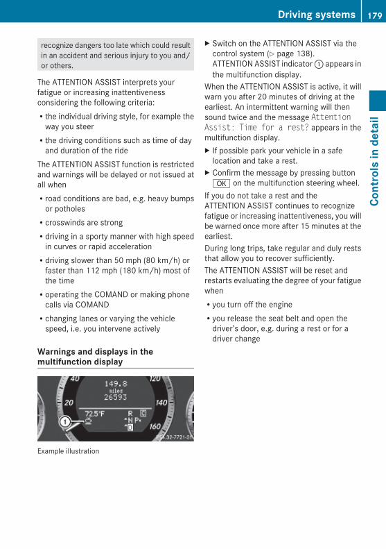
recognize dangers too late which could resultin an accident and serious injury to you and/or others.
The ATTENTION ASSIST interprets yourfatigue or increasing inattentivenessconsidering the following criteria:Rthe individual driving style, for example the
way you steerRthe driving conditions such as time of day
and duration of the rideThe ATTENTION ASSIST function is restrictedand warnings will be delayed or not issued atall whenRroad conditions are bad, e.g. heavy bumps
or potholesRcrosswinds are strongRdriving in a sporty manner with high speed
in curves or rapid accelerationRdriving slower than 50 mph (80 km/h) or
faster than 112 mph (180 km/h) most ofthe timeRoperating the COMAND or making phone
calls via COMANDRchanging lanes or varying the vehicle
speed, i.e. you intervene actively
Warnings and displays in the multifunction display
Example illustration
X Switch on the ATTENTION ASSIST via thecontrol system (Y page 138).ATTENTION ASSIST indicator : appears inthe multifunction display.
When the ATTENTION ASSIST is active, it willwarn you after 20 minutes of driving at theearliest. An intermittent warning will thensound twice and the message Attention Assist: Time for a rest? appears in themultifunction display.X If possible park your vehicle in a safe
location and take a rest.X Confirm the message by pressing buttona on the multifunction steering wheel.
If you do not take a rest and theATTENTION ASSIST continues to recognizefatigue or increasing inattentiveness, you willbe warned once more after 15 minutes at theearliest.During long trips, take regular and duly reststhat allow you to recover sufficiently.The ATTENTION ASSIST will be reset andrestarts evaluating the degree of your fatiguewhenRyou turn off the engineRyou release the seat belt and open the
driver’s door, e.g. during a rest or for adriver change
Driving systems 179
Cont
rols
in d
etai
l
212_AKB; 2; 41, en-USd2ureepe, Version: 2.11.8.1
2009-07-17T09:14:21+02:00 - Seite 179
Z

Climate control system
Overview of climate control system functionsYour vehicle is equipped with either of the following climate control systems:
Dual-zone automatic climate control
USA only
Canada only
3-zone automatic climate control
Canada only
The dual-zone automatic climate controlcombines an automatic heating andventilation system with a cooling system.You can adjust the dual-zone automaticclimate control separately for the driver’sand passenger side.
The 3-zone automatic climate controlcombines an automatic heating andventilation system with a cooling system.You can adjust the 3-zone automatic climatecontrol separately for each zone in thevehicle.
Rear climate control
Canada only
The rear climate control allows separate climate settings for the rear compartment.
180 Climate control systemCo
ntro
ls in
det
ail
212_AKB; 2; 41, en-USd2ureepe, Version: 2.11.8.1
2009-07-17T09:14:21+02:00 - Seite 180

Control panels
Dual-zone automatic climate control
USA only
Function Recommendation/Notes
: Air distribution andair volume(automatic mode)
i Switch on the automatic mode. Theindicator lamp above button à comeson.
(Y page 186)
; Front defroster i Keep this setting selected only until thewindshield and the front door windows areclear again.
(Y page 189)
= ZONE-function on/off
(Y page 191)
? Air recirculation i Only use this function for a short time,e.g. in a tunnel. Otherwise, the windowscan fog up due to lack of fresh air.
(Y page 190)
A MAX COOL functionon/off
(Y page 190)
B A/C cooling on/off i Switch on/off the air conditioning. (Y page 185)
C Rear windowdefroster
(Y page 191)
D Climate control on/off
i Switch on/off the climate controlsystem.
(Y page 185)
E Temperaturecontrol, passengerside
i Set the temperature to 72‡ (22†). (Y page 186)
F Air distribution (Y page 189)
G Air volume (Y page 189)
Climate control system 181
Cont
rols
in d
etai
l
212_AKB; 2; 41, en-USd2ureepe, Version: 2.11.8.1
2009-07-17T09:14:21+02:00 - Seite 181
Z

Function Recommendation/Notes
H Temperaturecontrol, driver’s side
i Set the temperature to 72‡ (22†). (Y page 186)
I Display
Canada only
Function Recommendation/Notes
: Air recirculation i Only use this function for a short time,e.g. in a tunnel. Otherwise, the windowscan fog up due to lack of fresh air.
(Y page 190)
; Front defroster i Keep this setting selected only until thewindshield and the front door windows areclear again.
(Y page 189)
= ZONE-function on/off
(Y page 191)
? Display
A Air distribution andair volume(automatic mode)
i Switch on the automatic mode. Theindicator lamp above button à comeson.
(Y page 186)
B A/C cooling on/off i Switch on/off the air conditioning. (Y page 185)
C Rear windowdefroster
(Y page 191)
D Climate control on/off
i Switch on/off the climate controlsystem.
(Y page 185)
E Temperaturecontrol, passengerside
i Set the temperature to 72‡ (22†). (Y page 186)
F Air distribution (Y page 189)
182 Climate control systemCo
ntro
ls in
det
ail
212_AKB; 2; 41, en-USd2ureepe, Version: 2.11.8.1
2009-07-17T09:14:21+02:00 - Seite 182

Function Recommendation/Notes
G Air volume (Y page 189)
H Temperaturecontrol, driver’s side
i Set the temperature to 72‡ (22†). (Y page 186)
3-zone automatic climate control
Canada only
Function Recommendation/Notes
Front climate control panel
: Air distribution andair volume(automatic mode)
i Switch on the automatic mode. Theindicator lamp in button à comes on.
(Y page 186)
; Front defroster i Keep this setting selected only until thewindshield and the front side windows areclear again.
(Y page 189)
= ZONE-function on/off
(Y page 191)
? Display
A Air recirculation i Only use this function for a short time,e.g. in a tunnel. Otherwise, the windowscan fog up due to lack of fresh air.
(Y page 190)
Climate control system 183
Cont
rols
in d
etai
l
212_AKB; 2; 41, en-USd2ureepe, Version: 2.11.8.1
2009-07-17T09:14:21+02:00 - Seite 183
Z
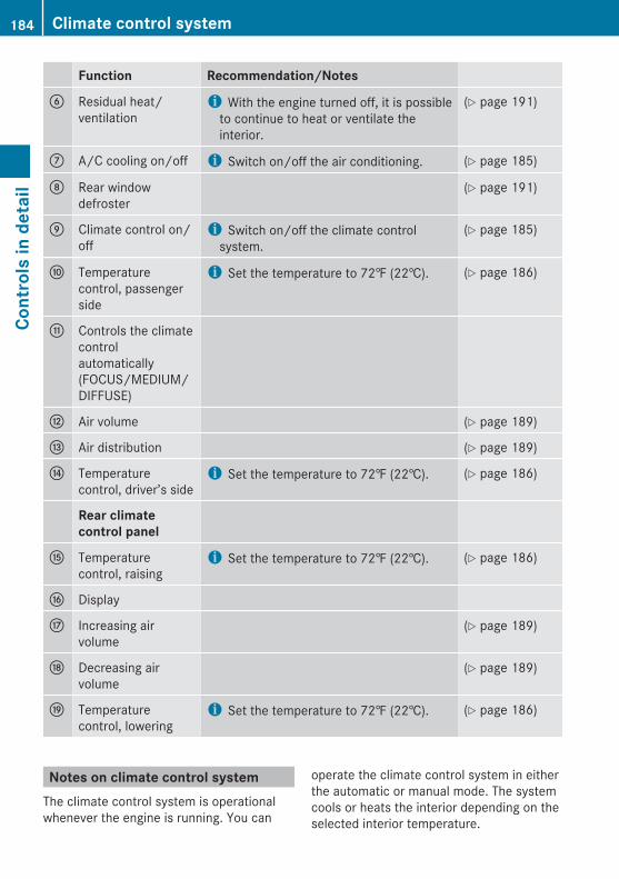
Function Recommendation/Notes
B Residual heat/ventilation
i With the engine turned off, it is possibleto continue to heat or ventilate theinterior.
(Y page 191)
C A/C cooling on/off i Switch on/off the air conditioning. (Y page 185)
D Rear windowdefroster
(Y page 191)
E Climate control on/off
i Switch on/off the climate controlsystem.
(Y page 185)
F Temperaturecontrol, passengerside
i Set the temperature to 72‡ (22†). (Y page 186)
G Controls the climatecontrolautomatically(FOCUS/MEDIUM/DIFFUSE)
H Air volume (Y page 189)
I Air distribution (Y page 189)
J Temperaturecontrol, driver’s side
i Set the temperature to 72‡ (22†). (Y page 186)
Rear climate control panel
K Temperaturecontrol, raising
i Set the temperature to 72‡ (22†). (Y page 186)
L Display
M Increasing airvolume
(Y page 189)
N Decreasing airvolume
(Y page 189)
O Temperaturecontrol, lowering
i Set the temperature to 72‡ (22†). (Y page 186)
Notes on climate control systemThe climate control system is operationalwhenever the engine is running. You can
operate the climate control system in eitherthe automatic or manual mode. The systemcools or heats the interior depending on theselected interior temperature.
184 Climate control systemCo
ntro
ls in
det
ail
212_AKB; 2; 41, en-USd2ureepe, Version: 2.11.8.1
2009-07-17T09:14:21+02:00 - Seite 184

It can only function optimally when you aredriving with the windows, the tilt/slidingsunroof or tilt/sliding panel closed.Nearly all dust particles, pollutants and odorsare filtered out before outside air enters thepassenger compartment through the airdistribution system.
G Warning!Severe conditions (e.g. strong air pollution)may require replacement of the filter beforeits scheduled replacement interval. A cloggedfilter will reduce the air volume to the interiorand the windows could fog up, impairingvisibility and endangering you and others.Have a clogged filter replaced as soon aspossible at an authorized Mercedes-BenzCenter.
The air conditioning will not engage (nocooling) if the A/C mode (Y page 185) isdeactivated.
G Warning!Follow the recommended settings for heatingand cooling given on the following pages.Otherwise the windows could fog up,impairing visibility and endangering you andothers.
X Keep the air intake grille in front of thewindshield free of snow and debris.
Do not obstruct air flow by placing objects onthe air flow-through exhaust slots below therear window.
i If the vehicle interior is hot, ventilate theinterior before driving off, see “Summeropening feature” (Y page 107). The climatecontrol will then adjust the interiortemperature to the set value much faster.
Deactivating the climate control system
G Warning!When the climate control system isdeactivated, the outside air supply andcirculation are also deactivated. Only choosethis setting for a short time. Otherwise thewindows could fog up, impairing visibility andendangering you and others.
X Deactivating: Press button ^.The indicator lamp above the button comeson.
X Reactivating: Press button ^.The indicator lamp above the button goesout. The previous settings are once againin effect.
orX Press button Ã.
The indicator lamp above the button comeson. Air volume and air distribution areadjusted automatically.
Air conditioningThe air conditioning is operational while theengine is running and cools the interior air tothe temperature set by the operator. Inaddition, the air conditioning dehumidifiesthe interior air and helps prevent windowfogging.
G Warning!If you deactivate the air conditioning, thevehicle will not be cooled when weatherconditions are warm. The windows can fog upmore quickly. Window fogging may impairvisibility and endanger you and others.
i Condensated water may drip out fromunderneath the vehicle. This is normal andnot an indication of a malfunction.
Climate control system 185
Cont
rols
in d
etai
l
212_AKB; 2; 41, en-USd2ureepe, Version: 2.11.8.1
2009-07-17T09:14:21+02:00 - Seite 185
Z
The air conditioning uses the refrigerantR134a. This refrigerant is free of CFCs whichare harmful to the ozone layer.
DeactivatingIt is possible to deactivate the airconditioning. The interior air will then nolonger be cooled or dehumidified.X Press button ¿.
The indicator lamp above the button goesout.The cooling function switches off after ashort delay.
ActivatingMoist air can fog up the windows. You candehumidify the interior air with the airconditioning.X Press button ¿.
The indicator lamp above the button comeson.
Automatic modeWhen operating the climate control system inautomatic mode, the interior air temperature,air volume and air distribution are adjustedautomatically.In automatic mode, cooling withdehumidification is switched on. This functioncan be switched off if necessary.
G Warning!If you deactivate the air conditioning, thevehicle will not be cooled when weatherconditions are warm. The windows can fog upmore quickly. Window fogging may impairvisibility and endanger you and others.
Dual-zone automatic climate controlX Set the desired temperature
(Y page 186).X Activating: Press button Ã.
The indicator lamp above the button comeson. The air volume and air distribution areadjusted automatically.
X Deactivating: Press rocker switch F orG (Y page 181).
orX Press button ¬ or button Ù (USA
only)The indicator lamp above button à goesout.
3-zone automatic climate controlX Set the desired temperature
(Y page 186).X Activating: Press button Ã.
The indicator lamp above the button comeson. The air volume and air distribution areadjusted automatically.
X Press rocker switch G (Y page 183) up ordown and select the desired level.
The automatic air conditioning settings:FOCUS Air flow high/air distribution via
the center and side air ventsMEDIUM Air flow medium/air distribution
via the center and side air ventsDIFFUSE Air flow low/air distribution via the
center, side and defroster air ventsX Deactivating: Press rocker switch H orI (Y page 183).The indicator lamp above button à goesout.
Setting temperature
Dual-zone automatic climate controlYou can adjust the air temperature on eachside of the passenger compartment. Youshould raise or lower the temperature setting
186 Climate control systemCo
ntro
ls in
det
ail
212_AKB; 2; 41, en-USd2ureepe, Version: 2.11.8.1
2009-07-17T09:14:21+02:00 - Seite 186

in small increments, preferably starting at72‡ (22†).X Increasing/decreasing: Press rocker
switch E or H (Y page 181) up or down.
3-zone automatic climate controlYou can set the air temperature for each ofthe 3 zones separately. You should raise orlower the temperature setting in smallincrements, preferably starting at 72‡(22†).
Front zonesX Increasing/decreasing: Press rocker
switch F or J (Y page 183) up or down.
Rear zonesX Increasing/decreasing: Press rocker
switch F or J (Y page 183) up or down.
Rear climate controlX Increasing/decreasing: Press button K
or O (Y page 183).
Adjusting air vents
G Warning!When operating the climate control, the airthat enters the passenger compartmentthrough the air vents can be very hot or verycold (depending on the set temperature). Thismay cause burns or frostbite to unprotectedskin in the immediate area of the air vents.
Always keep sufficient distance betweenunprotected parts of the body and the airvents. If necessary, use the air distributionadjustment to direct the air to air vents in thevehicle interior that are not in the immediatearea of unprotected skin.
For best possible performance of the climatecontrol:X Keep the air intake grille in front of the
windshield free of snow, leaves, sticks, andany other debris.
X Always keep all air vents and grilles in thepassenger compartment free fromobstruction.
i For draft-free ventilation, move theadjustable center and side air vents to themiddle position.
Center air vents
: Left center air vent, adjustable; Right center air vent, adjustable= Thumbwheel for air volume control for
adjustable right center air vent? Thumbwheel for air volume control for
adjustable left center air vent
X Opening/closing: Turn thumbwheels =and ? upward or downward.
Climate control system 187
Cont
rols
in d
etai
l
212_AKB; 2; 41, en-USd2ureepe, Version: 2.11.8.1
2009-07-17T09:14:21+02:00 - Seite 187
Z

Side air vents
Example illustration driver’s side: Left side defroster air vent, fixed; Left side air vent, adjustable= Thumbwheel for air volume control for
adjustable left side air vent
X Opening/closing: Turn thumbwheel =upward or downward.
Ventilated glove boxThe glove box can be ventilated, for instanceto cool its contents, when the climate controlsystem is activated. The level of airflow to theglove box depends on the airflow and airdistribution settings. The temperature of theair is approximately the same as that of theair flowing from the center air vents.
! Close the glove box air vent when heatingthe vehicle interior. Activate the airconditioning (cooling function) when theoutside temperature is high. Otherwise,temperature-sensitive items stored in theglove box could be damaged.
: Thumbwheel; Air vent
X Opening/closing: Turn thumbwheel :clockwise or counterclockwise.
Rear center console air vents
: Thumbwheel for air volume control forrear center air vents
; Right rear center air vent, adjustable= Rear climate control panel (3-zone
automatic climate control, Canada only)? Left rear center air vent, adjustable
X Opening/closing: Turn thumbwheel :upward or downward.
188 Climate control systemCo
ntro
ls in
det
ail
212_AKB; 2; 41, en-USd2ureepe, Version: 2.11.8.1
2009-07-17T09:14:21+02:00 - Seite 188

B-pillar air vents
Vehicles with 3-zone automatic climate control,Canada only: Side air vent, adjustable; Thumbwheel for air volume control for
side air vent
X Opening/closing: Turn thumbwheel ; tothe left or to the right.
Adjusting air distributionUSA only: The symbols shown in display I(Y page 181) on the climate control panelrepresent the following functions:Canada only: The symbols shown indisplay ? (Y page 181) or (Y page 183) onthe climate control panel represent thefollowing functions:
Symbol Function
¯ Directs air through thedefroster air vents to thewindshield and door windows
P Directs air through the centerand side air vents
S Directs air through the centerand side air vents and to thefootwells, USA only
b Directs air through the center,side and defroster air vents tothe windshield and doorwindows, Canada only
Symbol Function
O Directs air to the footwells
a Directs air through thedefroster air vents to thewindshield and door windowsand to the footwells
X USA only: Press rocker switch F(Y page 181) up or down until you haveselect the desired setting and thecorresponding symbol is shown in displayI.
X Canada only: Press rocker switch F(Y page 181) or I (Y page 183) up or downuntil you have select the desired settingand the corresponding symbol is shown indisplay ?.
Adjusting air volume
Dual-zone automatic climate controlX Decreasing/increasing: Press rocker
switch G (Y page 181) up or down.
3-zone automatic climate controlX Decreasing/increasing: Press rocker
switch H (Y page 183) up or down.
Rear air volume control with the rear climate control panelX Decreasing/increasing: Press button M
or N (Y page 183).
Front defrosterYou can use this setting to defrost thewindshield, for example if it is iced up.You can also defog the windshield and thefront door windows.
Climate control system 189
Cont
rols
in d
etai
l
212_AKB; 2; 41, en-USd2ureepe, Version: 2.11.8.1
2009-07-17T09:14:21+02:00 - Seite 189
Z

i Keep this setting selected only until thewindshield or the front door windows areclear again.
X Activating: Press button ¬.The indicator lamp above the button comeson.
The climate control switches to the followingfunctions automatically:Rcooling on to dehumidifyRmost efficient blower speed and heating
power, depending on outside temperatureRair flows onto the windshield and the front
door windowsRthe air recirculation mode is switched off
i You can adjust the air volume when thefront defroster is switched on.
X Deactivating: Press button ¬.The indicator lamp above the button goesout. The previous settings are once againin effect. The cooling remains switched on.The air recirculation remains switched off.
orX Press button Ã.
The indicator lamp above button ¬ goesout. Air volume and air distribution areadjusted automatically.
orX Dual-zone automatic climate control:
Press rocker switch E or H(Y page 181) up or down.3-zone automatic climate control: Pressrocker switch F or J (Y page 183) up ordown.
Maximum cooling MAX COOLMAX COOL is only available in U.S. vehicles.MAX COOL is only operational when theengine is running.You can use this setting to provide the fastestpossible cooling of the vehicle interior (when
windows and tilt/sliding sunroof or tilt/sliding panel are closed).X Activating: Press button Ù.
The indicator lamp above the button comeson.
The climate control switches automatically tothe following functions:Rmaximum coolingRmaximum blowing powerRthe air recirculation mode is switched onX Deactivating: Press button Ù again.
The indicator lamp above the button goesout. The previous settings are once againin effect.
Air recirculation modeSwitch to air recirculation mode to preventunpleasant odors from entering the vehiclefrom the outside (e. g. before driving througha tunnel). This setting cuts off the intake ofoutside air and recirculates the air in thepassenger compartment.
G Warning!Fogged windows impair visibility,endangering you and others. If the windowsbegin to fog on the inside, switching off theair recirculation mode immediately shouldclear interior window fogging. If interiorwindow fogging persists, make sure the airconditioning is activated, or press button¬.
X Activating: Press button g.The indicator lamp above the button comeson.
i The air recirculation mode is activatedautomatically at high outsidetemperatures.The indicator lamp in button g is not litwhen the air recirculation mode is switchedon automatically.
190 Climate control systemCo
ntro
ls in
det
ail
212_AKB; 2; 41, en-USd2ureepe, Version: 2.11.8.1
2009-07-17T09:14:21+02:00 - Seite 190
A quantity of outside air is added afterapproximately 30 minutes.
X Deactivating: Press button g again.The indicator lamp above the button goesout.
i The manually selected air recirculationmode is deactivated automatically:Rafter 5 minutes if the outside
temperature is below approximately41‡ (5†)Rafter 5 minutes if the air conditioning is
turned offRafter 30 minutes if the outside
temperature is above approximately41‡ (5†)
Residual heat and ventilationThis feature is only available in Canadavehicles with 3-zone automatic climatecontrol.With the engine turned off, it is possible tocontinue to heat or ventilate the interior forup to 30 minutes. This feature makes use ofthe residual heat produced by the engine.
i If you switch on the residual heat functionwhen outside temperatures are high, onlythe ventilation will be switched on.
X Activating: Switch off the ignition.X Press button Ì.
The indicator lamp above the button comeson.
X Deactivating: Press button Ì.The indicator lamp above the button goesout.
The residual heat is deactivatedautomatically:Rwhen the ignition is switched onRafter approximately 30 minutesRif the battery voltage drops
ZONE functionThe temperature can be adjusted for eachzone individually.
Dual-zone automatic climate controlX Activating: Press button á, rocker
switch E (Y page 181) or rocker switchF (Y page 183).The indicator lamp above button ácomes on.The temperature can be adjusted for eachzone individually.
X Deactivating: Press button á.The indicator lamp above the button goesout.The temperature can be adjusted for allzones via the driver’s-side settings.
3-zone automatic climate controlX Activating: Press button á.
The indicator lamp above the button comeson.The temperature can be adjusted for eachzone individually.
X Deactivating: Press button á.The indicator lamp above the button goesout.The temperature can be adjusted for allzones via the driver’s-side settings.
Rear window defroster
G Warning!Any accumulation of snow and ice should beremoved from the rear window before driving.Visibility could otherwise be impaired,endangering you and others.
The rear window defroster uses a largeamount of power. To keep the battery drainto a minimum, switch off the defroster assoon as the rear window is clear. Thedefroster is switched off automatically after
Rear window defroster 191
Cont
rols
in d
etai
l
212_AKB; 2; 41, en-USd2ureepe, Version: 2.11.8.1
2009-07-17T09:14:21+02:00 - Seite 191
Z
some time of operation depending on theoutside temperature.X Switch on the ignition.X Switching on: Press button ¤.
The indicator lamp above the button comeson.
X Switching off: Press button ¤ again.The rear window defroster switches off whenthe battery voltage is too low. Too manyelectrical consumers may be operatingsimultaneously.X Switch off consumers that are currently not
needed if required.
Power tilt/sliding sunroof
Opening and closing
G Observe Safety notes, see page 56.
G Warning!When opening or closing the tilt/slidingsunroof, make sure there is no danger ofanyone being harmed by the opening/closingprocedure.The tilt/sliding sunroof is equipped with theexpress operation and automatic reversalfunction. If the movement of the tilt/slidingsunroof is blocked during the closingprocedure, the tilt/sliding sunroof will stopand open slightly.The tilt/sliding sunroof operates differentlywhen the sunroof switch is pressed and held.See the “Closing when the tilt/sliding sunroofis blocked” section for details.The opening/closing procedure of the tilt/sliding sunroof can be immediately halted byreleasing the sunroof switch or, if the sunroofswitch was moved past the resistance pointand released, by moving the sunroof switch inany direction.
G Warning!The tilt/sliding sunroof is made out of glass.In the event of an accident, the glass may
shatter. This may result in an opening in theroof.In a vehicle rollover, occupants not wearingtheir seat belts or not wearing them properlymay be thrown out of the opening. Such anopening also presents a potential for injury foroccupants wearing their seat belts properly asentire body parts or portions of them mayprotrude from the passenger compartment.
! To avoid damaging the seals, do nottransport any objects with sharp edgeswhich can stick out of the tilt/slidingsunroof.Do not open the tilt/sliding sunroof if thereis snow or ice on the roof, as this couldresult in malfunctions.If you cannot open or close the tilt/slidingsunroof due to a malfunction contactRoadside Assistance or an authorizedMercedes-Benz Center.
! Please keep in mind that weatherconditions can sometimes change rapidly.Make sure to close the tilt/sliding sunroofwhen leaving the vehicle. If water entersthe vehicle interior, vehicle electronicscould be damaged which is not covered bythe Mercedes-Benz Limited Warranty.
i You can also open or close the tilt/slidingsunroof using the SmartKey or theKEYLESS-GO function, see “Summeropening feature” (Y page 107) and“Convenience closing feature”(Y page 108).
i After switching off the ignition orremoving the SmartKey from the starterswitch, you can operate the tilt/slidingsunroof until you open the driver’s or frontpassenger door. If no door was opened youcan operate the tilt/sliding sunroof for upto 5 minutes.
192 Power tilt/sliding sunroofCo
ntro
ls in
det
ail
212_AKB; 2; 41, en-USd2ureepe, Version: 2.11.8.1
2009-07-17T09:14:21+02:00 - Seite 192
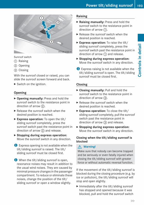
Sunroof switch: Raising; Opening= Closing
With the sunroof closed or raised, you canslide the sunroof screen forward and back.X Switch on the ignition.
OpeningX Opening manually: Press and hold the
sunroof switch to the resistance point indirection of arrow ;.
X Release the sunroof switch when thedesired position is reached.
X Express operation: To open the tilt/sliding sunroof completely, press thesunroof switch past the resistance point indirection of arrow ; and release.
X Stopping during express operation:Move the sunroof switch in any direction.
i Express opening is not available when thetilt/sliding sunroof is raised. The tilt/sliding sunroof must be closed first.
i When the tilt/sliding sunroof is open,resonance noises may result in addition tothe usual wind noises. They are caused byminimal pressure changes in the passengercompartment. To reduce or eliminate thesenoises, change the position of the tilt/sliding sunroof or open a window slightly.
RaisingX Raising manually: Press and hold the
sunroof switch to the resistance point indirection of arrow :.
X Release the sunroof switch when thedesired position is reached.
X Express operation: To raise the tilt/sliding sunroof completely, press thesunroof switch past the resistance point indirection of arrow : and release.
X Stopping during express operation:Move the sunroof switch in any direction.
i Express raising is not available when thetilt/sliding sunroof is open. The tilt/slidingsunroof must be closed first.
ClosingX Closing manually: Pull and hold the
sunroof switch to the resistance point indirection of arrow =.
X Release the sunroof switch when thedesired position is reached.
X Express operation: To close the tilt/sliding sunroof completely, pull the sunroofswitch past the resistance point indirection of arrow = and release.
X Stopping during express operation:Move the sunroof switch in any direction.
Closing when the tilt/sliding sunroof is blockedG Warning!Make sure that nobody can become trappedand be seriously or even fatally injured whenclosing the tilt/sliding sunroof with greaterforce or without automatic reversal function.
If the movement of the tilt/sliding sunroof isblocked during the closing procedure (e.g. byice or pollution), the tilt/sliding sunroof willstop and open slightly.X Immediately after the tilt/sliding sunroof
has stopped and opened because it wasblocked, pull and hold the sunroof switch
Power tilt/sliding sunroof 193
Cont
rols
in d
etai
l
212_AKB; 2; 41, en-USd2ureepe, Version: 2.11.8.1
2009-07-17T09:14:21+02:00 - Seite 193
Z

in direction of arrow = until the tilt/slidingsunroof is fully closed.The tilt/sliding sunroof closes with greaterforce.
If the tilt/sliding sunroof is blocked again andopens slightly:X Immediately after the tilt/sliding sunroof
was blocked and has opened, pull and holdthe sunroof switch in direction of arrow= until the tilt/sliding sunroof is fullyclosed.The tilt/sliding sunroof closes withoutautomatic reversal function.
G Warning!Pulling and holding the sunroof switch toclose the tilt/sliding sunroof immediatelyafter it had been blocked two times will causethe tilt/sliding sunroof to close without anyreversal function for as long as you hold thesunroof switch.
SynchronizingThe tilt/sliding sunroof must be synchronizedafter a malfunction or if it does not opensmoothly.
! If the tilt/sliding sunroof cannot be closedor synchronized, contact an authorizedMercedes-Benz Center or call RoadsideAssistance.
X Switch on the ignition.X Press and hold the sunroof switch in
direction of arrow : (Y page 193) until thetilt/sliding sunroof is fully raised at therear.
X Keep holding the sunroof switch indirection of arrow : for approximately1 second.
X Check the express operation feature(Y page 193).If the tilt/sliding sunroof opens and closescompletely, the roof is synchronized.Otherwise repeat the above steps.
Panorama roof with power tilt/sliding panel
Extending and retracting the roller sunblinds
The roller sunblinds only operate with the tilt/sliding panel closed. The front and rear rollersunblind cannot be operated individually.
G Warning!When extending the roller sunblinds, makesure no one is in danger of being injured bythe extending procedure.The roller sunblinds are equipped with theexpress operation and automatic reversalfunction. If the movement of the rollersunblinds is blocked during the extendingprocedure, the roller sunblinds will stop andretract slightly.The extending of the roller sunblinds can beimmediately halted by releasing the roof panelswitch or, if the roof panel switch was movedpast the resistance point and released, bymoving the roof panel switch in any direction.
Roof panel switch: Retracting; Retracting= Extending
X Switch on the ignition.X Retracting/Extending: Move the roof
panel switch to the resistance point in therequired direction of arrow :, ; or =
194 Panorama roof with power tilt/sliding panelCo
ntro
ls in
det
ail
212_AKB; 2; 41, en-USd2ureepe, Version: 2.11.8.1
2009-07-17T09:14:21+02:00 - Seite 194

until the roller sunblinds have reached theirdesired position.
X Express operation: Move the roof panelswitch past the resistance point indirection of arrow :, ; or = and release.The roller sunblinds retract/extendcompletely.
X Stopping during express operation:Move the roof panel switch in any direction.
Opening and closing the panorama roof with power tilt/sliding panel
G Observe Safety notes, see page 56.
G Warning!When opening or closing the tilt/sliding panel,make sure there is no danger of anyone beingharmed by the opening/closing procedure.The tilt/sliding panel is equipped with theexpress operation and automatic reversalfunction. If the movement of the tilt/slidingpanel is blocked during the closing procedure,the tilt/sliding panel will stop and openslightly.The tilt/sliding panel operates differentlywhen the roof panel switch is pressed andheld. See the “Closing when the tilt/slidingpanel is blocked” section in this chapter fordetails.The opening/closing procedure of the tilt/sliding panel can be immediately halted byreleasing the roof panel switch or, if the roofpanel switch was moved past the resistancepoint and released, by moving the roof panelswitch in any direction.
G Warning!The panorama roof with tilt/sliding panel ismade out of glass. In the event of an accident,the glass may shatter. This may result in anopening in the roof.In a vehicle rollover, occupants not wearingtheir seat belts or not wearing them properlymay be thrown out of the opening. Such an
opening also presents a potential for injury foroccupants wearing their seat belts properly asentire body parts or portions of them mayprotrude from the passenger compartment.
! To avoid damaging the seals, do nottransport any objects with sharp edgeswhich can stick out of the tilt/sliding panel.Do not open the tilt/sliding panel if there issnow or ice on the roof, as this could resultin malfunctions.
! Please keep in mind that weatherconditions can sometimes change rapidly.Make sure to close the tilt/sliding panelwhen leaving the vehicle. If water entersthe vehicle interior, vehicle electronicscould be damaged which is not covered bythe Mercedes-Benz Limited Warranty.
Roof panel switch: Raising; Opening= Closing
The tilt/sliding panel only operates with theroller sunblinds retracted.
i You can also open or close the tilt/slidingpanel using the SmartKey, see “Summeropening feature” (Y page 107) or see“Convenience closing feature”(Y page 108).
X Switch on the ignition.
Panorama roof with power tilt/sliding panel 195
Cont
rols
in d
etai
l
212_AKB; 2; 41, en-USd2ureepe, Version: 2.11.8.1
2009-07-17T09:14:21+02:00 - Seite 195
Z

OpeningX Opening manually: Press and hold the
roof panel switch to the resistance point indirection of arrow ;.
X Release the roof panel switch when thedesired position is reached.
X Express operation: To open the tilt/sliding panel completely, press the roofpanel switch past the resistance point indirection of arrow ; and release.
X Stopping during express operation:Move the roof panel switch in any direction.
i When the tilt/sliding panel is open,resonance noises may result in addition tothe usual wind noises. They are caused byminimal pressure changes in the passengercompartment. To reduce or eliminate thesenoises, change the position of the tilt/sliding panel or open a window slightly.
RaisingX Raising manually: Press and hold the roof
panel switch to the resistance point indirection of arrow :.
X Release the roof panel switch when thedesired position is reached.
X Express operation: To raise the tilt/sliding panel completely, press the roofpanel switch past the resistance point indirection of arrow : and release.
X Stopping during express operation:Move the roof panel switch in any direction.
i Express raising is not available when thetilt/sliding panel is open. The tilt/slidingpanel must be closed first.
ClosingX Closing manually: Pull and hold the roof
panel switch to the resistance point indirection of arrow =.
X Release the roof panel switch when thedesired position is reached.
X Express operation: To close the tilt/sliding panel completely, pull the roof panelswitch past the resistance point indirection of arrow = and release.
X Stopping during express operation:Move the roof panel switch in any direction.
Closing when the tilt/sliding panel is blockedG Warning!Make sure that nobody can become trappedand be seriously or even fatally injured whenclosing the tilt/sliding panel withoutautomatic reversal function.
If the movement of the tilt/sliding panel isblocked during the closing procedure (e.g. byice or pollution), the tilt/sliding panel will stopand open slightly.X Immediately after the tilt/sliding panel has
stopped and opened because it wasblocked, pull and hold the roof panel switchin direction of arrow = until the tilt/slidingpanel is fully closed.
If the tilt/sliding panel is blocked again andopens slightly:X Immediately after the tilt/sliding panel was
blocked and has opened, pull and hold theroof panel switch in direction of arrow =until the tilt/sliding panel is fully closed.The tilt sliding panel closes withoutautomatic reversal function.
G Warning!Pulling and holding the roof panel switch toclose the tilt/sliding panel immediately afterit had been blocked two times will cause thetilt/sliding panel to close without any reversalfunction for as long as you hold the roof panelswitch.
SynchronizingThe tilt/sliding panel and roller sunblindsmust be synchronized after a malfunction or
196 Panorama roof with power tilt/sliding panelCo
ntro
ls in
det
ail
212_AKB; 2; 41, en-USd2ureepe, Version: 2.11.8.1
2009-07-17T09:14:21+02:00 - Seite 196

if the tilt/sliding panel does not opensmoothly.
! Do not attempt to open the tilt/slidingpanel before the tilt/sliding panel isproperly synchronized. The tilt/slidingpanel could otherwise lock-up in the openposition.If the tilt/sliding panel cannot be closed orsynchronized, contact an authorizedMercedes-Benz Center or call RoadsideAssistance.
X Switch on the ignition.X Pull the roof panel switch repeatedly in
direction of arrow = to the resistancepoint until the tilt/sliding panel is closedcompletely.
X Pull and hold the roof panel switch indirection of arrow = for 1 more second.
X Pull the roof panel switch repeatedly indirection of arrow = to the resistancepoint until the roller sunblinds are closedcompletely.
X Pull and hold the roof panel switch indirection of arrow = for 1 more second.
X Check whether the tilt/sliding panel andthe roller sunblinds can be openedcompletely (Y page 195).
Loading and storing
Loading instructions
G Warning!Always fasten items being carried as securelyas possible. Use cargo tie-down rings andfastening materials appropriate for the weightand size of the load.In an accident, during hard braking or suddenmaneuvers, loose items will be thrown aroundinside the vehicle. This can cause injury tovehicle occupants unless the items aresecurely fastened in the vehicle.
To help avoid personal injury during a collisionor sudden maneuver, exercise care whentransporting cargo. Do not pile luggage orcargo higher than the seat backrests.The trunk is the preferred place to carryobjects.Never drive a vehicle with the trunk open.Deadly carbon monoxide (CO) gases mayenter vehicle interior resulting inunconsciousness and death.
Load distribution
The total load weight including vehicleoccupants and luggage/cargo should notexceed the total load limit indicated on thecorresponding Tire and Loading Informationplacard located on the driver’s door B-pillar(Y page 238).The handling characteristics of a fully loadedvehicle depend greatly on the loaddistribution. It is therefore recommended toload the vehicle according to the illustrationshown. The heaviest items are to be placedtowards the front of the vehicle.Please pay attention to and comply with thefollowing instructions when loading thevehicle and transporting cargo:RAlways place items being carried against
front or rear seat backrests, and fastenthem as securely as possible.RThe heaviest portion of the cargo should
always be kept as low as possible againstfront or rear seat backrests.
Loading and storing 197
Cont
rols
in d
etai
l
212_AKB; 2; 41, en-USd2ureepe, Version: 2.11.8.1
2009-07-17T09:14:21+02:00 - Seite 197
Z

Roof rackFor information about further roof rackequipment, contact an authorized Mercedes-Benz Center.
G Warning!Only use roof racks approved by Mercedes-Benz for your vehicle model to avoid damageto the vehicle.Follow the manufacturer’s installationinstructions. Otherwise, an improperlyattached roof rack system or its load couldbecome detached from the vehicle.Do not exceed the maximum roof load of220 lb (100 kg).Take into consideration that when the roofrack is loaded, the handling characteristicsare different from those when operating thevehicle without the roof rack loaded.
Make sureRyou can raise the power tilt/sliding sunroof
or the panorama roof with tilt/sliding panelcompletelyRyou can open the trunk completely
Vehicles with power tilt/sliding sunroof
Vehicles with panorama roof with power tilt/sliding panel
X Flip trim covers : open.X Only attach the roof rack to the anchorage
points under trim covers :.X Observe manufacturer’s instructions for
installation.
Through-loading feature
G Warning!Do not transport any unsecured items in thethrough-loading area.
X Fold the rear armrest down.X Opening through-loading area: Open the
trunk.
X Press release button :.The cover opens.
X Closing through-loading area: Swingcover in trunk back until it engages.
198 Loading and storingCo
ntro
ls in
det
ail
212_AKB; 2; 41, en-USd2ureepe, Version: 2.11.8.1
2009-07-17T09:14:21+02:00 - Seite 198
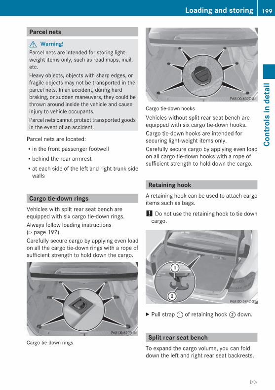
Parcel nets
G Warning!Parcel nets are intended for storing light-weight items only, such as road maps, mail,etc.Heavy objects, objects with sharp edges, orfragile objects may not be transported in theparcel nets. In an accident, during hardbraking, or sudden maneuvers, they could bethrown around inside the vehicle and causeinjury to vehicle occupants.Parcel nets cannot protect transported goodsin the event of an accident.
Parcel nets are located:Rin the front passenger footwellRbehind the rear armrestRat each side of the left and right trunk side
walls
Cargo tie-down ringsVehicles with split rear seat bench areequipped with six cargo tie-down rings.Always follow loading instructions(Y page 197).Carefully secure cargo by applying even loadon all the cargo tie-down rings with a rope ofsufficient strength to hold down the cargo.
Cargo tie-down rings
Cargo tie-down hooks
Vehicles without split rear seat bench areequipped with six cargo tie-down hooks.Cargo tie-down hooks are intended forsecuring light-weight items only.Carefully secure cargo by applying even loadon all cargo tie-down hooks with a rope ofsufficient strength to hold down the cargo.
Retaining hookA retaining hook can be used to attach cargoitems such as bags.
! Do not use the retaining hook to tie downcargo.
X Pull strap : of retaining hook ; down.
Split rear seat benchTo expand the cargo volume, you can folddown the left and right rear seat backrests.
Loading and storing 199
Cont
rols
in d
etai
l
212_AKB; 2; 41, en-USd2ureepe, Version: 2.11.8.1
2009-07-17T09:14:21+02:00 - Seite 199
Z

The two sections can be folded downseparately.
G Warning!When expanding the cargo volume, alwaysfold the seat backrests fully forward.Unless you are transporting cargo, the seatbackrests must remain properly locked in theupright position.In an accident, during hard braking or suddenmaneuvers, loose items will be thrown aroundinside the vehicle. This can cause injury tovehicle occupants unless the items aresecurely fastened in the vehicle.Always use the cargo tie-down rings.
Folding seat backrest forwardX Open the trunk.
X Pull on left and/or right release handle :.The driver’s and/or front passenger seatmoves forward automatically.
X Fold seat backrests ; forward.X Adjust front seats to desired position
(Y page 88).
Setting up seat backrest
X Fold seat backrest : rearward until itengages.
! Make sure that the seat belt is notpinched.
X Check for secure locking by pushing andpulling on the seat backrest.
X Adjust head restraints, if necessary(Y page 90).
X Adjust front seats to desired position(Y page 88).
G Warning!Always lock the seat backrest in its uprightposition when the rear seat bench isoccupied, or the extended cargo volume is notin use.Check for secure locking by pushing andpulling on the seat backrest.In an accident, during hard braking or suddenmaneuvers, loose items will be thrown aroundinside the vehicle. This can cause injury tovehicle occupants unless the items aresecurely fastened in the vehicle.To help avoid personal injury during a collisionor sudden maneuver, exercise care whentransporting cargo.
200 Loading and storingCo
ntro
ls in
det
ail
212_AKB; 2; 41, en-USd2ureepe, Version: 2.11.8.1
2009-07-17T09:14:21+02:00 - Seite 200
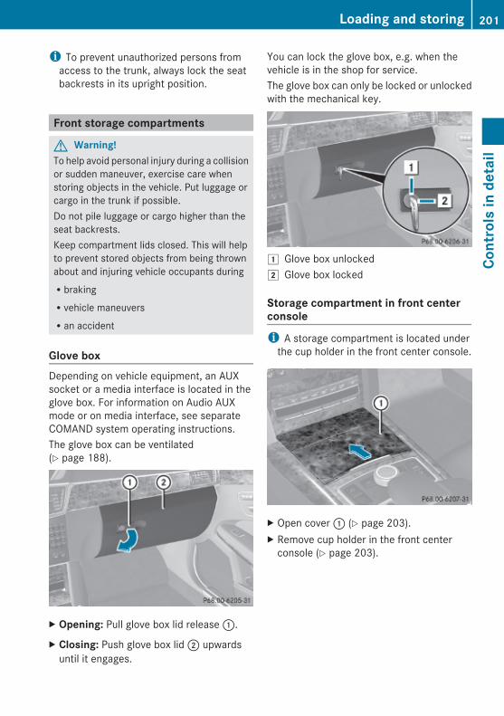
i To prevent unauthorized persons fromaccess to the trunk, always lock the seatbackrests in its upright position.
Front storage compartments
G Warning!To help avoid personal injury during a collisionor sudden maneuver, exercise care whenstoring objects in the vehicle. Put luggage orcargo in the trunk if possible.Do not pile luggage or cargo higher than theseat backrests.Keep compartment lids closed. This will helpto prevent stored objects from being thrownabout and injuring vehicle occupants duringRbrakingRvehicle maneuversRan accident
Glove box Depending on vehicle equipment, an AUXsocket or a media interface is located in theglove box. For information on Audio AUXmode or on media interface, see separateCOMAND system operating instructions.The glove box can be ventilated(Y page 188).
X Opening: Pull glove box lid release :.
X Closing: Push glove box lid ; upwardsuntil it engages.
You can lock the glove box, e.g. when thevehicle is in the shop for service.The glove box can only be locked or unlockedwith the mechanical key.
1 Glove box unlocked2 Glove box locked
Storage compartment in front center consolei A storage compartment is located under
the cup holder in the front center console.
X Open cover : (Y page 203).X Remove cup holder in the front center
console (Y page 203).
Loading and storing 201
Cont
rols
in d
etai
l
212_AKB; 2; 41, en-USd2ureepe, Version: 2.11.8.1
2009-07-17T09:14:21+02:00 - Seite 201
Z
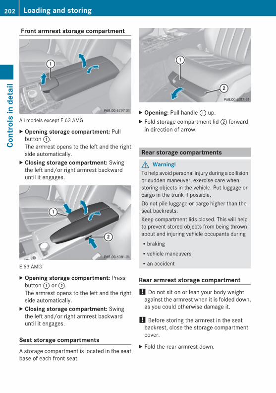
Front armrest storage compartment
All models except E 63 AMG
X Opening storage compartment: Pullbutton :.The armrest opens to the left and the rightside automatically.
X Closing storage compartment: Swingthe left and/or right armrest backwarduntil it engages.
E 63 AMG
X Opening storage compartment: Pressbutton : or ;.The armrest opens to the left and the rightside automatically.
X Closing storage compartment: Swingthe left and/or right armrest backwarduntil it engages.
Seat storage compartmentsA storage compartment is located in the seatbase of each front seat.
X Opening: Pull handle : up.X Fold storage compartment lid ; forward
in direction of arrow.
Rear storage compartments
G Warning!To help avoid personal injury during a collisionor sudden maneuver, exercise care whenstoring objects in the vehicle. Put luggage orcargo in the trunk if possible.Do not pile luggage or cargo higher than theseat backrests.Keep compartment lids closed. This will helpto prevent stored objects from being thrownabout and injuring vehicle occupants duringRbrakingRvehicle maneuversRan accident
Rear armrest storage compartment ! Do not sit on or lean your body weight
against the armrest when it is folded down,as you could otherwise damage it.
! Before storing the armrest in the seatbackrest, close the storage compartmentcover.
X Fold the rear armrest down.
202 Loading and storingCo
ntro
ls in
det
ail
212_AKB; 2; 41, en-USd2ureepe, Version: 2.11.8.1
2009-07-17T09:14:21+02:00 - Seite 202
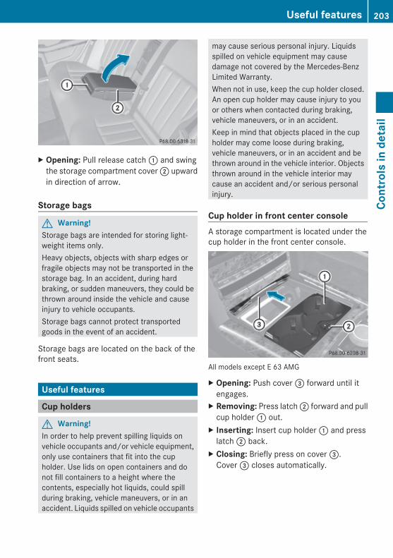
X Opening: Pull release catch : and swingthe storage compartment cover ; upwardin direction of arrow.
Storage bags
G Warning!Storage bags are intended for storing light-weight items only.Heavy objects, objects with sharp edges orfragile objects may not be transported in thestorage bag. In an accident, during hardbraking, or sudden maneuvers, they could bethrown around inside the vehicle and causeinjury to vehicle occupants.Storage bags cannot protect transportedgoods in the event of an accident.
Storage bags are located on the back of thefront seats.
Useful features
Cup holders
G Warning!In order to help prevent spilling liquids onvehicle occupants and/or vehicle equipment,only use containers that fit into the cupholder. Use lids on open containers and donot fill containers to a height where thecontents, especially hot liquids, could spillduring braking, vehicle maneuvers, or in anaccident. Liquids spilled on vehicle occupants
may cause serious personal injury. Liquidsspilled on vehicle equipment may causedamage not covered by the Mercedes-BenzLimited Warranty.When not in use, keep the cup holder closed.An open cup holder may cause injury to youor others when contacted during braking,vehicle maneuvers, or in an accident.Keep in mind that objects placed in the cupholder may come loose during braking,vehicle maneuvers, or in an accident and bethrown around in the vehicle interior. Objectsthrown around in the vehicle interior maycause an accident and/or serious personalinjury.
Cup holder in front center consoleA storage compartment is located under thecup holder in the front center console.
All models except E 63 AMG
X Opening: Push cover = forward until itengages.
X Removing: Press latch ; forward and pullcup holder : out.
X Inserting: Insert cup holder : and presslatch ; back.
X Closing: Briefly press on cover =.Cover = closes automatically.
Useful features 203
Cont
rols
in d
etai
l
212_AKB; 2; 41, en-USd2ureepe, Version: 2.11.8.1
2009-07-17T09:14:21+02:00 - Seite 203
Z
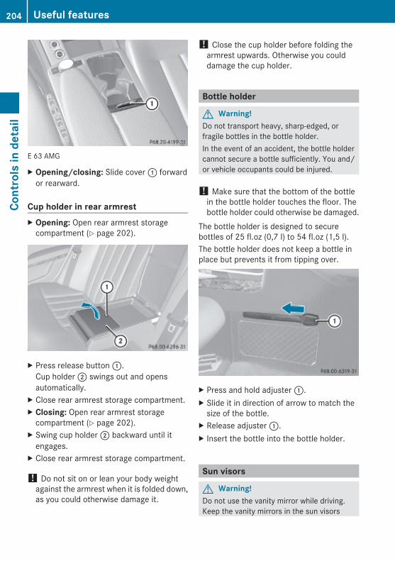
E 63 AMG
X Opening/closing: Slide cover : forwardor rearward.
Cup holder in rear armrest X Opening: Open rear armrest storage
compartment (Y page 202).
X Press release button :.Cup holder ; swings out and opensautomatically.
X Close rear armrest storage compartment.X Closing: Open rear armrest storage
compartment (Y page 202).X Swing cup holder ; backward until it
engages.X Close rear armrest storage compartment.
! Do not sit on or lean your body weightagainst the armrest when it is folded down,as you could otherwise damage it.
! Close the cup holder before folding thearmrest upwards. Otherwise you coulddamage the cup holder.
Bottle holder
G Warning!Do not transport heavy, sharp-edged, orfragile bottles in the bottle holder.In the event of an accident, the bottle holdercannot secure a bottle sufficiently. You and/or vehicle occupants could be injured.
! Make sure that the bottom of the bottlein the bottle holder touches the floor. Thebottle holder could otherwise be damaged.
The bottle holder is designed to securebottles of 25 fl.oz (0,7 l) to 54 fl.oz (1,5 l).The bottle holder does not keep a bottle inplace but prevents it from tipping over.
X Press and hold adjuster :.X Slide it in direction of arrow to match the
size of the bottle.X Release adjuster :.X Insert the bottle into the bottle holder.
Sun visors
G Warning!Do not use the vanity mirror while driving.Keep the vanity mirrors in the sun visors
204 Useful featuresCo
ntro
ls in
det
ail
212_AKB; 2; 41, en-USd2ureepe, Version: 2.11.8.1
2009-07-17T09:14:21+02:00 - Seite 204

closed while vehicle is in motion. Reflectedglare can endanger you and others.
: Sun visor; Additional sun visor= Mounting? Holder, e.g. for gas cardsA Vanity mirrorB Vanity mirror cover
Glare through the windshieldX Flip sun visor : down when you
experience glare.
Glare through a door windowX Close vanity mirror cover B if opened.X Disengage sun visor : from mounting =.X Pivot sun visor to the side.
X Adjust sun visor : by pushing or pulling indirection of arrows.
X Flip down additional sun visor ; when youexperience additional glare through thewindshield.
Vanity mirrorThe vanity mirror lamp only functions whenthe sun visor : is engaged in mounting =.X Flip sun visor : down.X Lift up vanity mirror cover B.
Vanity mirror lamp comes on.
Rear window sunshade
G Warning!When operating the rear window sunshademake sure there is no danger of anyone beingharmed by the extending or retractingprocedure.The extending or retracting procedure can beimmediately halted by briefly pressing rearwindow sunshade switch. To reverse directionof movement, press rear window sunshadeswitch again.
G Observe Safety notes, see page 56.
X Switch on the ignition.X Extending/Retracting: Press rear
window sunshade switch : briefly.
Useful features 205
Cont
rols
in d
etai
l
212_AKB; 2; 41, en-USd2ureepe, Version: 2.11.8.1
2009-07-17T09:14:21+02:00 - Seite 205
Z
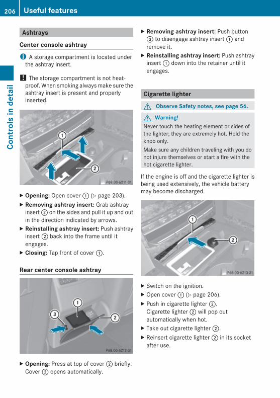
Ashtrays
Center console ashtray i A storage compartment is located under
the ashtray insert.
! The storage compartment is not heat-proof. When smoking always make sure theashtray insert is present and properlyinserted.
X Opening: Open cover : (Y page 203).X Removing ashtray insert: Grab ashtray
insert ; on the sides and pull it up and outin the direction indicated by arrows.
X Reinstalling ashtray insert: Push ashtrayinsert ; back into the frame until itengages.
X Closing: Tap front of cover :.
Rear center console ashtray
X Opening: Press at top of cover ; briefly.Cover ; opens automatically.
X Removing ashtray insert: Push button= to disengage ashtray insert : andremove it.
X Reinstalling ashtray insert: Push ashtrayinsert : down into the retainer until itengages.
Cigarette lighter
G Observe Safety notes, see page 56.
G Warning!Never touch the heating element or sides ofthe lighter; they are extremely hot. Hold theknob only.Make sure any children traveling with you donot injure themselves or start a fire with thehot cigarette lighter.
If the engine is off and the cigarette lighter isbeing used extensively, the vehicle batterymay become discharged.
X Switch on the ignition.X Open cover : (Y page 206).X Push in cigarette lighter ;.
Cigarette lighter ; will pop outautomatically when hot.
X Take out cigarette lighter ;.X Reinsert cigarette lighter ; in its socket
after use.
206 Useful featuresCo
ntro
ls in
det
ail
212_AKB; 2; 41, en-USd2ureepe, Version: 2.11.8.1
2009-07-17T09:14:21+02:00 - Seite 206

Power outletsThe power outlets can be used toaccommodate 12V DC electrical accessories(e.g. auxiliary lamps, mobile phone chargers)up to a maximum of 15 A (180 W).If the engine is off and the power outlets arebeing used extensively, the vehicle batterymay become discharged.
Power outlet in glove boxX Open the glove box (Y page 201).
Power outlet in rear passenger compartment
X Briefly press top of cover :.Cover : opens automatically.
Power outlet in trunk
Tele Aid! In order to activate the Tele Aid system, a
subscriber agreement must be completed.To ensure your system is activated andoperational, please press Informationbutton ï to perform the acquaintancecall. Failure to complete either of thesesteps may result in a system that is notactivated.If you have any questions regardingactivation, please call the CustomerAssistance Center at1-800-FOR-MERCedes (1-800-367-6372)(USA only) or 1-888-923-8367 (Canadaonly).
Shortly after the completion of your Tele Aidacquaintance call, you will receive a user IDand password in the mail. You may use thispassword to access the Tele Aid section in“Owner’s Online” at www.mbusa.com (USAonly). The “My Tele Aid” section will give youaccess to account information, remote doorunlock and more.The Tele Aid system is available ifRit has been activated and is operational.
Activation requires a subscription formonitoring services, connection andcellular air timeRvehicle battery power is availableRthe relevant cellular phone network and
GPS signals are available and pass the
Useful features 207
Cont
rols
in d
etai
l
212_AKB; 2; 41, en-USd2ureepe, Version: 2.11.8.1
2009-07-17T09:14:21+02:00 - Seite 207
Z
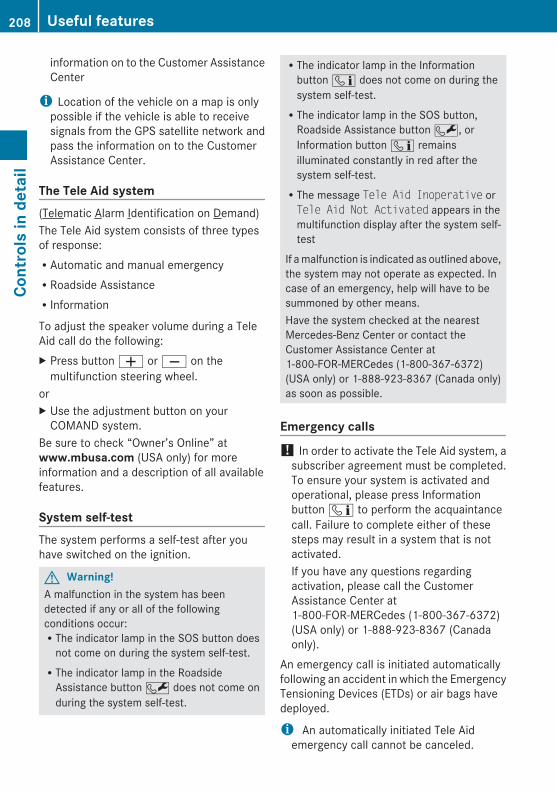
information on to the Customer AssistanceCenter
i Location of the vehicle on a map is onlypossible if the vehicle is able to receivesignals from the GPS satellite network andpass the information on to the CustomerAssistance Center.
The Tele Aid system(Telematic Alarm Identification on Demand)The Tele Aid system consists of three typesof response:RAutomatic and manual emergencyRRoadside AssistanceRInformation
To adjust the speaker volume during a TeleAid call do the following:X Press button W or X on the
multifunction steering wheel.orX Use the adjustment button on your
COMAND system.Be sure to check “Owner’s Online” atwww.mbusa.com (USA only) for moreinformation and a description of all availablefeatures.
System self-test The system performs a self-test after youhave switched on the ignition.
G Warning!A malfunction in the system has beendetected if any or all of the followingconditions occur:RThe indicator lamp in the SOS button does
not come on during the system self-test.RThe indicator lamp in the Roadside
Assistance button F does not come onduring the system self-test.
RThe indicator lamp in the Informationbutton ï does not come on during thesystem self-test.RThe indicator lamp in the SOS button,
Roadside Assistance button F, orInformation button ï remainsilluminated constantly in red after thesystem self-test.RThe message Tele Aid Inoperative orTele Aid Not Activated appears in themultifunction display after the system self-test
If a malfunction is indicated as outlined above,the system may not operate as expected. Incase of an emergency, help will have to besummoned by other means.Have the system checked at the nearestMercedes-Benz Center or contact theCustomer Assistance Center at1-800-FOR-MERCedes (1-800-367-6372)(USA only) or 1-888-923-8367 (Canada only)as soon as possible.
Emergency calls ! In order to activate the Tele Aid system, a
subscriber agreement must be completed.To ensure your system is activated andoperational, please press Informationbutton ï to perform the acquaintancecall. Failure to complete either of thesesteps may result in a system that is notactivated.If you have any questions regardingactivation, please call the CustomerAssistance Center at1-800-FOR-MERCedes (1-800-367-6372)(USA only) or 1-888-923-8367 (Canadaonly).
An emergency call is initiated automaticallyfollowing an accident in which the EmergencyTensioning Devices (ETDs) or air bags havedeployed.
i An automatically initiated Tele Aidemergency call cannot be canceled.
208 Useful featuresCo
ntro
ls in
det
ail
212_AKB; 2; 41, en-USd2ureepe, Version: 2.11.8.1
2009-07-17T09:14:21+02:00 - Seite 208
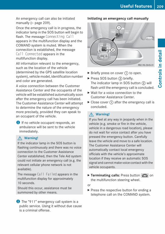
An emergency call can also be initiatedmanually (Y page 209).Once the emergency call is in progress, theindicator lamp in the SOS button will begin toflash. The message Connecting Callappears in the multifunction display and theCOMAND system is muted. When theconnection is established, the messageCall Connected appears in themultifunction display.All information relevant to the emergency,such as the location of the vehicle(determined by the GPS satellite locationsystem), vehicle model, identification numberand color are generated.A voice connection between the CustomerAssistance Center and the occupants of thevehicle will be established automatically soonafter the emergency call has been initiated.The Customer Assistance Center will attemptto determine the nature of the emergencymore precisely, provided they can speak toan occupant of the vehicle.
i If no vehicle occupant responds, anambulance will be sent to the vehicleimmediately.
G Warning!If the indicator lamp in the SOS button isflashing continuously and there was no voiceconnection to the Customer AssistanceCenter established, then the Tele Aid systemcould not initiate an emergency call (e.g. therelevant cellular phone network is notavailable).The message Call Failed appears in themultifunction display for approximately10 seconds.Should this occur, assistance must besummoned by other means.
i The “911” emergency call system is apublic service. Using it without due causeis a criminal offense.
Initiating an emergency call manually
X Briefly press on cover : to open.X Press SOS button ; briefly.
The indicator lamp in SOS button ; willflash until the emergency call is concluded.
X Wait for a voice connection to theCustomer Assistance Center.
X Close cover : after the emergency call isconcluded.
G Warning!If you feel at any way in jeopardy when in thevehicle (e.g. smoke or fire in the vehicle,vehicle in a dangerous road location), pleasedo not wait for voice contact after you havepressed the emergency button. Carefullyleave the vehicle and move to a safe location.The Customer Assistance Center willautomatically contact local emergencyofficials with the vehicle’s approximatelocation if they receive an automatic SOSsignal and cannot make voice contact with thevehicle occupants.
X Terminating calls: Press button ~ onthe multifunction steering wheel.
orX Press the respective button for ending a
telephone call on the COMAND system.
Useful features 209
Cont
rols
in d
etai
l
212_AKB; 2; 41, en-USd2ureepe, Version: 2.11.8.1
2009-07-17T09:14:21+02:00 - Seite 209
Z
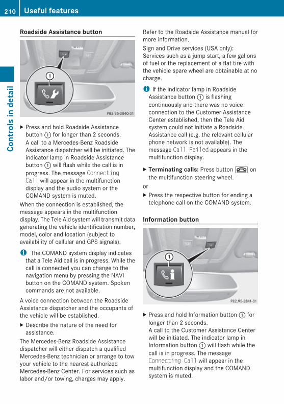
Roadside Assistance button
X Press and hold Roadside Assistancebutton : for longer than 2 seconds.A call to a Mercedes-Benz RoadsideAssistance dispatcher will be initiated. Theindicator lamp in Roadside Assistancebutton : will flash while the call is inprogress. The message Connecting Call will appear in the multifunctiondisplay and the audio system or theCOMAND system is muted.
When the connection is established, themessage appears in the multifunctiondisplay. The Tele Aid system will transmit datagenerating the vehicle identification number,model, color and location (subject toavailability of cellular and GPS signals).
i The COMAND system display indicatesthat a Tele Aid call is in progress. While thecall is connected you can change to thenavigation menu by pressing the NAVIbutton on the COMAND system. Spokencommands are not available.
A voice connection between the RoadsideAssistance dispatcher and the occupants ofthe vehicle will be established.X Describe the nature of the need for
assistance.The Mercedes-Benz Roadside Assistancedispatcher will either dispatch a qualifiedMercedes-Benz technician or arrange to towyour vehicle to the nearest authorizedMercedes-Benz Center. For services such aslabor and/or towing, charges may apply.
Refer to the Roadside Assistance manual formore information.Sign and Drive services (USA only):Services such as a jump start, a few gallonsof fuel or the replacement of a flat tire withthe vehicle spare wheel are obtainable at nocharge.
i If the indicator lamp in RoadsideAssistance button : is flashingcontinuously and there was no voiceconnection to the Customer AssistanceCenter established, then the Tele Aidsystem could not initiate a RoadsideAssistance call (e.g. the relevant cellularphone network is not available). Themessage Call Failed appears in themultifunction display.
X Terminating calls: Press button ~ onthe multifunction steering wheel.
orX Press the respective button for ending a
telephone call on the COMAND system.
Information button
X Press and hold Information button : forlonger than 2 seconds.A call to the Customer Assistance Centerwill be initiated. The indicator lamp inInformation button : will flash while thecall is in progress. The messageConnecting Call will appear in themultifunction display and the COMANDsystem is muted.
210 Useful featuresCo
ntro
ls in
det
ail
212_AKB; 2; 41, en-USd2ureepe, Version: 2.11.8.1
2009-07-17T09:14:21+02:00 - Seite 210

When the connection is established, themessage Call Connected appears in themultifunction display. The Tele Aid system willtransmit data generating the vehicleidentification number, model, color andlocation (subject to availability of cellular andGPS signals).
i The COMAND system display indicatesthat a Tele Aid call is in progress. While thecall is connected you can change to thenavigation menu by pressing the NAVIbutton on the COMAND system. Spokencommands are not available.
A voice connection between the CustomerAssistance Center representative and theoccupants of the vehicle will be established.Information regarding the operation of yourvehicle, the nearest authorized Mercedes-Benz Center or Mercedes-Benz USA productsand services is available to you.For more details concerning the Tele Aidsystem, please visit www.mbusa.com (USAonly), log in to “Owner’s Online” and visit the“My Tele Aid” section to learn more.
i If the indicator lamp in Informationbutton : is flashing continuously andthere was no voice connection to theCustomer Assistance Center established,then the Tele Aid system could not initiatean Information call (e.g. the relevantcellular phone network is not available).The message Call Failed appears in themultifunction display.
X Terminating calls: Press button ~ onthe multifunction steering wheel.
orX Press the respective button for ending a
telephone call on the COMAND system.
Call priorityIf other service calls such as a RoadsideAssistance call or Information call are active,an emergency call is still possible. In this
case, the emergency call will take priority andoverride all other active calls.The indicator lamp in the respective buttonflashes until the call is concluded. Automaticinitiated emergency calls can only beterminated by a Customer Assistance Centerrepresentative. All other calls can beterminated by pressing button ~ on themultifunction steering wheel or therespective button for ending a telephone callon the COMAND system.
i When a Tele Aid call has been initiated,the COMAND system audio is muted. Themobile phone is no longer connected to theCOMAND system. If you must use thisphone, we recommend that you use it onlywith the vehicle at a standstill in a safelocation.
Search & Send “Search & Send” is a navigation destinationaddress entry service. For more informationon “Search & Send”, refer to separateCOMAND system operating instructions.
Remote door unlock In case you have locked your vehicleunintentionally (e.g. SmartKey inside vehicle),and the reserve SmartKey is not available:X Contact the Customer Assistance Center
at 1-800-FOR-MERCedes(1-800-367-6372) (USA only) or1-888-923-8367 (Canada only).You will be asked to provide your password.
X Then return to your vehicle at the timearranged with the Customer AssistanceCenter and pull the trunk lid handle for aminimum of 20 seconds until the indicatorlamp in the SOS button is flashing.The message Connecting Call appears inthe multifunction display.
As an alternative, you may unlock the vehiclevia Internet in the “My Tele Aid” section of“Owner’s Online”, using your ID and password(USA only).
Useful features 211
Cont
rols
in d
etai
l
212_AKB; 2; 41, en-USd2ureepe, Version: 2.11.8.1
2009-07-17T09:14:21+02:00 - Seite 211
Z

i The remote door unlock feature isavailable if the relevant cellular phonenetwork is available.The SOS button will flash and the messageConnecting Call will appear in themultifunction display to indicate receipt ofthe door unlock command.If the trunk lid handle was pulled for morethan 20 seconds before door unlockauthorization was received, you must wait15 minutes before pulling the trunk lidhandle again.
Remote door lock If you have forgotten to lock your vehicle andare no longer near it, you can have it lockedremotely through the Customer AssistanceCenter.The vehicle can be remotely locked withinfour days after the ignition has been switchedoff.X Contact the Customer Assistance Center
at 1-800-FOR-MERCedes(1-800-367-6372) (USA only) or1-888-923-8367 (Canada only).You will be asked to provide your password.
When you are inside your vehicle the nexttime and switch on the ignition, the messageTele Aid Doors locked by remote control will appear on the multifunctiondisplay.
i The remote door lock feature is availableif the relevant cellular phone network isavailable and data connection is possible.
Stolen Vehicle Recovery Services In the event your vehicle was stolen:X Report the incident to the police.
The police will issue a numbered incidentreport.
X Pass this number on to the CustomerAssistance Center along with yourpassword.The Customer Assistance Center will thenattempt to covertly contact the vehicle’sTele Aid system. Once the vehicle islocated, the Customer Assistance Centerwill contact the local law enforcement andyou. The vehicle’s location will only beprovided to law enforcement.
i If the anti-theft alarm stays on for morethan 30 seconds, the Tele Aid system willnotify the Customer Assistance Centerautomatically.
Garage door openerThe integrated remote control can operate upto three separately controlled devicescompatible with HomeLink® or some othersystems.
G Warning!Before programming the integrated remotecontrol to a garage door opener or gateoperator, make sure people and objects areout of the way of the device to preventpotential harm or damage. Whenprogramming a garage door opener, the doormoves up or down. When programming a gateoperator, the gate opens or closes.Do not use the integrated remote control withany garage door opener that lacks safety stopand reverse features as required by U.S.federal safety standards (this includes anygarage door opener model manufacturedbefore April 1, 1982). A garage door thatcannot detect an object - signaling the doorto stop and reverse - does not meet currentU.S. federal safety standards.
212 Useful featuresCo
ntro
ls in
det
ail
212_AKB; 2; 41, en-USd2ureepe, Version: 2.11.8.1
2009-07-17T09:14:21+02:00 - Seite 212

When programming a garage door opener,park vehicle outside the garage.Do not run the engine while programming theintegrated remote control. Inhalation ofexhaust gas is hazardous to your health. Allexhaust gas contains carbon monoxide (CO),and inhaling it can cause unconsciousnessand possible death.
Interior rear view mirror with integrated remotecontrol
Hand-held remote control A is not part of thevehicle equipment.
Programming the integrated remote controlX Step 1: Switch on the ignition.X Step 2: If you have previously programmed
a signal transmitter button and wish toretain its programming, proceed to step 3.
orX If you are programming the integrated
remote control for the first time, press andhold the two outer signal transmitterbuttons ; and ? and release them whenindicator lamp : begins to flash afterapproximately 20 seconds.Do not hold the buttons for longer than30 seconds.This procedure erases any previoussettings for all three channels andinitializes the memory. If you later wish toprogram a second and/or third hand-heldtransmitter to the remaining two signal
transmitter buttons, do not repeat this stepand begin directly with step 3.
X Step 3: Hold the end of hand-held remotecontrol A of the device you wish to trainapproximately 2 to 12 in (5 to 30 cm) awayfrom the signal transmitter button (;, =or ?) to be programmed, while keepingindicator lamp : in view.
X Step 4: Using both hands, simultaneouslypress hand-held remote control button Band the desired signal transmitter button(;, = or ?). Do not release the buttonsuntil step 5 is completed.Indicator lamp : will flash, first slowly andthen rapidly.
i Indicator lamp : flashes immediatelythe first time the signal transmitter buttonis programmed. If this button has alreadybeen programmed, the indicator lamp willstart flashing after 20 seconds.
X Step 5: After indicator lamp : changesfrom a slow to a rapidly flashing light,release the hand-held remote controlbutton and the signal transmitter button.
X Step 6: Press and hold the just-trainedsignal transmitter button (;, = or ?) andobserve indicator lamp :.If indicator lamp : stays on constantly,programming is complete and your deviceshould activate when the respective signaltransmitter button (;, = or ?) is pressedand released.
i If indicator lamp : flashes rapidly forapproximately 2 seconds and then turns toa constant light, continue withprogramming steps 8 through 12 as yourgarage door opener may be equipped withthe “rolling code” feature.
X Step 7: To program the remaining twosignal transmitter buttons, repeat the stepsabove starting with step 3.
Useful features 213
Cont
rols
in d
etai
l
212_AKB; 2; 41, en-USd2ureepe, Version: 2.11.8.1
2009-07-17T09:14:21+02:00 - Seite 213
Z

Rolling code programmingTo train a garage door opener (or other rollingcode devices) with the rolling code feature,follow these instructions after completing the“Programming” portion (steps 1 through 6) ofthis text. For your convenience and tocomplete the procedure faster, you mightwant to have someone assist you.X Step 8: Locate the “training” button on the
garage door opener motor head unit.
i Exact location and color of the button mayvary by garage door opener brand.Depending on manufacturer, the “training”button may also be referred to as “learn” or“smart” button. If there is difficulty locatingthe transmitting button, refer to the garagedoor opener Operator’s Manual.
X Step 9: Press the “training” button on thegarage door opener motor head unit.The “training light” is activated.You have 30 seconds to initiate thefollowing two steps.
X Step 10: Return to the vehicle and firmlypress, hold for 2 seconds and release theprogrammed signal transmitter button (;,= or ?).
X Step 11: Press, hold for 2 seconds andrelease same signal transmitter button asecond time to complete the trainingprocess.
i Some garage door openers (or otherrolling code equipped devices) may requireyou to press, hold for 2 seconds andrelease the same signal transmitter buttona third time to complete the trainingprocess.
X Step 12: Confirm the garage dooroperation by pressing the programmedsignal transmitter button (;, = or ?).
X Step 13: To program the remaining twosignal transmitter buttons, repeat the stepsabove starting with step 3.
Gate operator/Canadian programmingCanadian radio-frequency laws requiretransmitter signals to “time-out” (or quit)after several seconds of transmission whichmay not be long enough for the integratedsignal transmitter to pick up the signal duringprogramming. Similar to this Canadian law,some U.S. gate operators are designed to“time-out” in the same manner.If you live in Canada or if you are havingdifficulties programming a gate operator(regardless of where you live) by using theprogramming procedures, replace step 4 withthe following:X Step 4: Press and hold the signal
transmitter button (;, = or ?). Do notrelease this button until it has beensuccessfully trained.
X While still holding down the signaltransmitter button (;, = or ?), “cycle”your hand-held remote control button Bas follows: Press and hold button B for2 seconds, then release it for 2 seconds,and again press and hold it for 2 seconds.Repeat this sequence on the hand-heldremote control until the frequency signalhas been learned.Upon successful training, indicatorlamp : will flash slowly and then rapidlyafter several seconds.
X Proceed with programming step 5 andstep 6 to complete.
i Upon completion of programming theintegrated remote control, make sure youretain the hand-held remote control thatcame with the garage door opener, gateoperator or other device. You may need itfor use in other vehicles, for futureprogramming of an integrated remotecontrol, or simply for continued use as ahand-held remote control to operate therespective device in other situations.
214 Useful featuresCo
ntro
ls in
det
ail
212_AKB; 2; 41, en-USd2ureepe, Version: 2.11.8.1
2009-07-17T09:14:21+02:00 - Seite 214
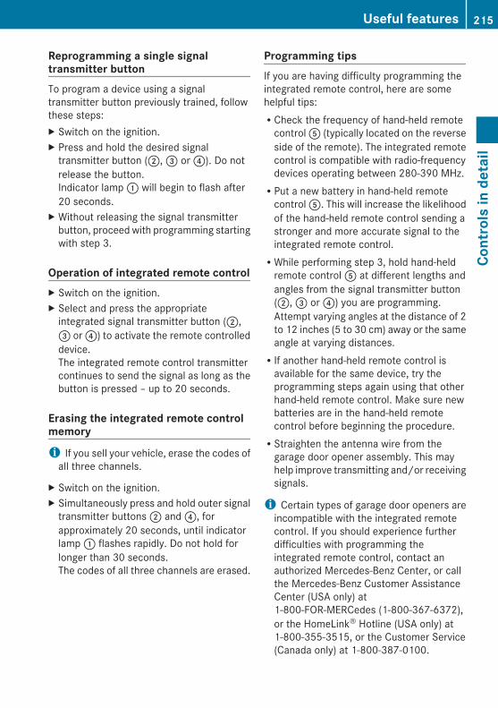
Reprogramming a single signal transmitter buttonTo program a device using a signaltransmitter button previously trained, followthese steps:X Switch on the ignition.X Press and hold the desired signal
transmitter button (;, = or ?). Do notrelease the button.Indicator lamp : will begin to flash after20 seconds.
X Without releasing the signal transmitterbutton, proceed with programming startingwith step 3.
Operation of integrated remote controlX Switch on the ignition.X Select and press the appropriate
integrated signal transmitter button (;,= or ?) to activate the remote controlleddevice.The integrated remote control transmittercontinues to send the signal as long as thebutton is pressed – up to 20 seconds.
Erasing the integrated remote control memoryi If you sell your vehicle, erase the codes of
all three channels.
X Switch on the ignition.X Simultaneously press and hold outer signal
transmitter buttons ; and ?, forapproximately 20 seconds, until indicatorlamp : flashes rapidly. Do not hold forlonger than 30 seconds.The codes of all three channels are erased.
Programming tipsIf you are having difficulty programming theintegrated remote control, here are somehelpful tips:RCheck the frequency of hand-held remote
control A (typically located on the reverseside of the remote). The integrated remotecontrol is compatible with radio-frequencydevices operating between 280-390 MHz.RPut a new battery in hand-held remote
control A. This will increase the likelihoodof the hand-held remote control sending astronger and more accurate signal to theintegrated remote control.RWhile performing step 3, hold hand-held
remote control A at different lengths andangles from the signal transmitter button(;, = or ?) you are programming.Attempt varying angles at the distance of 2to 12 inches (5 to 30 cm) away or the sameangle at varying distances.RIf another hand-held remote control is
available for the same device, try theprogramming steps again using that otherhand-held remote control. Make sure newbatteries are in the hand-held remotecontrol before beginning the procedure.RStraighten the antenna wire from the
garage door opener assembly. This mayhelp improve transmitting and/or receivingsignals.
i Certain types of garage door openers areincompatible with the integrated remotecontrol. If you should experience furtherdifficulties with programming theintegrated remote control, contact anauthorized Mercedes-Benz Center, or callthe Mercedes-Benz Customer AssistanceCenter (USA only) at1-800-FOR-MERCedes (1-800-367-6372),or the HomeLink® Hotline (USA only) at1-800-355-3515, or the Customer Service(Canada only) at 1-800-387-0100.
Useful features 215
Cont
rols
in d
etai
l
212_AKB; 2; 41, en-USd2ureepe, Version: 2.11.8.1
2009-07-17T09:14:21+02:00 - Seite 215
Z

i USA only:This device complies with Part 15 of theFCC Rules. Operation is subject to thefollowing two conditions:1. This device may not cause harmful
interference, and2. this device must accept any
interference received, includinginterference that may cause undesiredoperation.
Any unauthorized modification to thisdevice could void the user’s authority tooperate the equipment.
i Canada only:This device complies with RSS-210 ofIndustry Canada. Operation is subject tothe following two conditions:1. This device may not cause interference,
and2. this device must accept any
interference received, includinginterference that may cause undesiredoperation of the device.
Any unauthorized modification to thisdevice could void the user’s authority tooperate the equipment.
Compass
i In order to receive an accurate reading inthe interior rear view mirror :, the
compass must be calibrated and themagnetic field zone set.
X Calling up the compass: Press button= briefly.The compass displays the direction intowhich the vehicle is currently traveling: N,NE, E, SE, S, SW, W, or NW.
X Compass adjustment: Determine yourlocation on the basis of the following zonemaps.
Zone map North America
Zone map South America
216 Useful featuresCo
ntro
ls in
det
ail
212_AKB; 2; 41, en-USd2ureepe, Version: 2.11.8.1
2009-07-17T09:14:21+02:00 - Seite 216
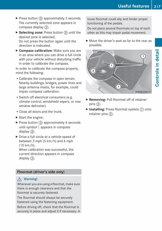
X Press button = approximately 3 seconds.The currently selected zone appears incompass display ;.
X Selecting zone: Press button = until thedesired zone is selected.Do not press the button again until thedirection is indicated.
X Compass calibration: Make sure you arein an area where you can drive a full circlewith your vehicle without disturbing trafficin order to calibrate the compass.
In order to calibrate the compass properly,mind the following:RCalibrate the compass in open terrain.
Nearby buildings, bridges, power lines andlarge antenna masts, for example, couldimpair compass calibration.RSwitch off electrical consumers (e.g.
climate control, windshield wipers, or rearwindow defroster).RClose all doors and the trunk.X Start the engine.X Press button = approximately 6 seconds
until symbol C appears in compassdisplay ;.
X Drive a full circle at a vehicle speed ofbetween 3 mph (5 km/h) and 6 mph(10 km/h).When calibration was successful, thecurrent direction appears in compassdisplay ;.
Floormat (driver’s side only)
G Warning!Whenever you are using a floormat, make surethere is enough clearance and that thefloormat is securely fastened.The floormat should always be securelyfastened using the fastening equipment.Before driving off, check that the floormat issecurely in place and adjust it if necessary. A
loose floormat could slip and hinder properfunctioning of the pedals.Do not place several floormats on top of eachother as this may impair pedal movement.
X Move the driver’s seat as far to the rear aspossible.
X Removing: Pull floormat off of retainerpins ;.
X Installing: Press floormat eyelets : ontoretainer pins ;.
Useful features 217
Cont
rols
in d
etai
l
212_AKB; 2; 41, en-USd2ureepe, Version: 2.11.8.1
2009-07-17T09:14:21+02:00 - Seite 217
Z

218
212_AKB; 2; 41, en-USd2ureepe, Version: 2.11.8.1
2009-07-17T09:14:21+02:00 - Seite 218
Vehicle equipment ............................ 220The first 1000 miles (1500 km) ....... 220At the gas station ............................. 220Engine compartment ........................ 223Tires and wheels ............................... 228Winter driving ................................... 252Driving instructions .......................... 254Maintenance ...................................... 258Vehicle care ....................................... 260
219
Oper
atio
n
212_AKB; 2; 41, en-USd2ureepe, Version: 2.11.8.1
2009-07-17T09:14:21+02:00 - Seite 219
Vehicle equipment
i This Operator’s Manual describes allfeatures, standard or optional, potentiallyavailable for your vehicle at the time ofpurchase. Please be aware that yourvehicle might not be equipped with allfeatures described in this manual.
The first 1000 miles (1500 km)
The more cautiously you treat your vehicleduring the break-in period, the more satisfiedyou will be with its performance later on.RDrive your vehicle during the first
1 000 miles (1 500 km) at varying butmoderate vehicle and engine speeds.RDuring this period, avoid heavy loads (full
throttle driving) and excessive enginespeeds (no more than 2/3 of maximum rpmin each gear).RAvoid accelerating by kickdown.RSelect gear ranges 3, 2 or 1 (Y page 120)
only when driving at moderate speeds (forhill driving).
After 1 000 miles (1 500 km) you maygradually increase vehicle and engine speedsto the permissible maximum.
! Additional instructions for AMG vehicles:RDuring the first 1 000 miles (1 500 km),
do not exceed a speed of 85 mph(140 km/h).RDuring this period, avoid engine speeds
above 4 500 rpm in each gear.RShift gears in a timely manner.
All of the above instructions, as may apply toyour vehicle type, also apply when driving thefirst 1 000 miles (1 500 km) after the engineor the rear differential has been replaced.
i Always obey applicable speed limits.
Notes on breaking-in the rear differential (AMG vehicles only)
The vehicle is equipped with a self-lockingrear differential. For increased protection ofthe rear differential, carry out an oil changeafter a break-in phase of 2 000 miles(3 000 km). This oil change will extend theuseful life of the differential. Have the oilchange carried out at a qualified specialistworkshop. Mercedes-Benz recommends youhave this work done at a authorizedMercedes-Benz Center.
At the gas station
Refueling
G Warning!Gasoline and diesel fuels are highly flammableand poisonous. They burn violently and cancause serious injury.Never allow sparks, flames or smokingmaterials near gasoline or diesel fuel!Turn off the engine before refueling.Whenever you are around gasoline or dieselfuel, avoid inhaling fumes and any skin orclothing contact. Extinguish all smokingmaterials.Direct skin contact with fuels and theinhalation of fuel vapors are damaging yourhealth.
G Warning!Overfilling of the fuel tank may createpressure in the system which could cause agas discharge. This could cause the gas tospray back out when removing the fuel pumpnozzle, which could cause personal injury.
G Warning!Do not fill diesel tanks with gasoline. Do notmix diesel fuel with gasoline. Otherwise thefuel system and engine could be damaged. Inaddition, the vehicle could catch fire.
220 At the gas stationOp
erat
ion
212_AKB; 2; 41, en-USd2ureepe, Version: 2.11.8.1
2009-07-17T09:14:21+02:00 - Seite 220
! Never refuel vehicles with gasoline enginewith diesel fuel. Never refuel vehicles withdiesel engine with gasoline. Even smallamounts of incorrect fuel will damage thefuel system and engine. Damage resultingfrom the use of non-approved fuels or fueladditives or resulting from mixing gasolinewith diesel fuel or vice versa is not coveredby the Mercedes-Benz Limited Warranty.
! If you have accidentally filled the tankwith incorrect or non-approved fuel, do notswitch on the ignition. Otherwise theincorrect or non-approved fuel will get intothe fuel lines. The fuel system must bedrained completely. Contact an authorizedMercedes-Benz Center to have the fuelsystem drained completely.
! Gasoline engine:To prevent damage to the catalyticconverters, only use premium unleadedgasoline in this vehicle.Any noticeable irregularities in engineoperation should be repaired promptly.Otherwise, excessive unburned fuel mayreach the catalytic converter, causing it tooverheat and potentially start a fire.
! Diesel engine:When filling the diesel fuel tank using fuelcontainers, place a filling filter, a suedecloth or a clean flannel cloth as a filter.Otherwise, particles from the fuel containercould clog the fuel lines and/or the dieselinjection system.
! Diesel engine:The engine is more susceptible to wear anddamage if you useRmarine diesel fuelRheating oilRadditivesThe exhaust aftertreatment device will beseriously damaged if you use any otherdiesel fuel than ULTRA-LOW SULFUR
HIGHWAY DIESEL FUEL (ULSD, 15 ppmSULFUR MAXIMUM).The use of such non-approved fuels and/orspecial additives is not covered by theMercedes-Benz Limited Warranty.
i Gasoline engine:Only use premium unleaded gasoline witha minimum Posted Octane Rating of 91(average of 96 RON/86 MON).Information on gasoline quality cannormally be found on the fuel pump. Pleasecontact gas station personnel in caselabels on the pump cannot be found.For more information on gasoline, see“Premium unleaded gasoline (gasolineengine)” (Y page 362), see “Fuelrequirements” (Y page 363), or contact anauthorized Mercedes-Benz Center, or visitwww.mbusa.com (USA only).
i Diesel engine:Only use commercially available vehicularULTRA-LOW SULFUR HIGHWAY DIESELFUEL (ULSD, 15 ppm SULFUR MAXIMUM).Information on diesel quality can normallybe found on the fuel pump. Please contactgas station personnel in case labels on thepump cannot be found.For more information on diesel fuels, see“Fuel requirements” (Y page 363), orcontact an authorized Mercedes-BenzCenter, or visit www.mbusa.com (USAonly).
i Diesel engine:If you have driven the vehicle until the tankis empty, the fuel system needs to be bled(Y page 333).
Locking/unlocking the vehicle with theSmartKey or KEYLESS-GO automaticallylocks/unlocks the fuel filler flap.
i In case the central locking system doesnot release the fuel filler flap, see “Fuel fillerflap” (Y page 316).
At the gas station 221
Oper
atio
n
212_AKB; 2; 41, en-USd2ureepe, Version: 2.11.8.1
2009-07-17T09:14:21+02:00 - Seite 221
Z

The fuel filler flap is located on the right-handside of the vehicle towards the rear.
X Turn off the engine.
i Leaving the engine running and the fuelfiller cap open can cause the yellow enginemalfunction indicator lamp ; toilluminate.For more information, see also “Practicalhints” (Y page 310).
X Remove the SmartKey from the starterswitch.KEYLESS-GO: Open the driver’s door. Thisputs the starter switch in position 0, sameas with the SmartKey removed from thestarter switch. The driver’s door then canbe closed again.
X Opening: Press fuel filler flap : at thepoint indicated by the arrow.
X Turn fuel filler cap ; counterclockwise.X Take off fuel filler cap ;.
! The fuel filler cap is tethered to the fuelfiller neck. Do not drop the cap. It coulddamage the vehicle paint finish.
X Place fuel filler cap ; in direction of arrowinto holder =.
X Fully insert filler nozzle unit and refuel.X Only fill your tank until the filler nozzle unit
cuts out – do not top off or overfill.
X Closing: Turn fuel filler cap ; clockwiseuntil it audibly engages.
i Close the fuel filler flap before locking thevehicle. Otherwise the flap locking pin willprevent closing the fuel filler flap.
X Close fuel filler flap :.
Low outside temperatures (diesel engine)! Do not fill the tank with gasoline. Do not
blend diesel fuel with gasoline or kerosene.The fuel system and engine will otherwisebe damaged, which is not covered by theMercedes-Benz Limited Warranty.
To prevent malfunctions, diesel fuel withimproved cold flow characteristics is offeredin the winter months. Check with your fuelretailer.
Check regularly and before a long tripFor information on quantities andrequirements of operating agents, see “Fuels,coolants, lubricants, etc.” (Y page 359).Check the following:REngine oil level (Y page 224)RTire inflation pressure (Y page 231)RCoolant level (Y page 226)RVehicle lighting (Y page 318)RWasher system and headlamp cleaning
system (Y page 227)RBrake fluid (Y page 227)
222 At the gas stationOp
erat
ion
212_AKB; 2; 41, en-USd2ureepe, Version: 2.11.8.1
2009-07-17T09:14:21+02:00 - Seite 222

Engine compartment
Hood
G Warning!Do not pull the release lever while the vehicleis in motion. Otherwise the hood could beforced open by passing air flow.This could cause the hood to come loose andinjure you and/or others.
Opening
G Warning!Do not open the hood when the engine isoverheated. You could be seriously injured.Observe the coolant temperature gauge todetermine whether the engine may beoverheated. If you see flames or smokecoming from the engine compartment, moveaway from the vehicle. Wait until the enginehas cooled. If necessary, call the firedepartment.
G Warning!You could be injured when the hood is open –even when the engine is turned off.Parts of the engine can become very hot. Toprevent burns, let the engine cool completelybefore touching any components on thevehicle. Comply with all relevant safetyprecautions.
G Warning!To help prevent personal injury, stay clear ofmoving parts when the hood is open and theengine is running.The radiator fan may continue to run forapproximately 30 seconds or may evenrestart after the engine has been turned off.Stay clear of fan blades.
G Warning!Vehicles with gasoline engine:The engine is equipped with a transistorizedignition system. Because of the high voltageit is dangerous to touch any components(ignition coils, spark plug sockets, diagnosticsocket) of the ignition systemRwith the engine runningRwhile starting the engineRwhen the ignition is switched on and the
engine is turned manually
G Warning!Vehicles with diesel engine:The engine is equipped with a high-voltageelectronic control unit for the injectionsystem. Because of the high voltage it isdangerous to touch any components of theinjection system (injectors, electrical wires)Rwith the engine runningRwhile starting the engineRwhen the ignition is switched on
X Pull hood lock release lever :.The hood is unlocked.
! Never open the hood if the wiper arms arefolded forward away from the windshield.Otherwise the windshield wipers or thehood could be damaged.
Engine compartment 223
Oper
atio
n
212_AKB; 2; 41, en-USd2ureepe, Version: 2.11.8.1
2009-07-17T09:14:21+02:00 - Seite 223
Z

X Push handle ; under the hood upwards.X Pull up on the hood and then release it.
The hood will be held open at shoulderheight by gas-filled struts automatically.
Closing
G Warning!When closing the hood, use extreme cautionnot to catch hands or fingers. Be careful thatyou do not close the hood on anyone.Make sure the hood is securely engagedbefore driving off. Do not continue driving ifthe hood can no longer engage after anaccident, for example. The hood couldotherwise come loose while the vehicle is inmotion and injure you and/or others.
X Let the hood drop from a height ofapproximately 8 in (20 cm).
X Check to make sure the hood is fullyclosed.If you can raise the hood at a point abovethe headlamps, then it is not properlyclosed. Open it again and let it drop withsomewhat greater force.
Radiatori Vehicles with diesel engine:
Do not cover the radiator, for example witha winter front or bug cover. Otherwise thereadings of the on-board diagnostic systemmay be inaccurate. Some of theses
readings are required by law and must beaccurate at all times.
Engine oilThe amount of oil your engine consumes willdepend on a number of factors, includingdriving style. Increased oil consumption canoccur when the vehicle is new or the vehicleis driven frequently at higher engine speeds.Engine oil consumption checks should onlybe made after the vehicle break-in period.
! Do not use any special lubricant additives,as these may damage the drive assemblies.Using special additives not approved byMercedes-Benz may cause damage notcovered by the Mercedes-Benz LimitedWarranty.For further information contact anauthorized Mercedes-Benz Center.
Notes on checking engine oil levelWhen checking the oil levelRthe vehicle must be parked on level groundRwith the engine at operating temperature,
the vehicle must have been stationary forat least 5 minutes with the engine turnedoffRwith the engine not at operating
temperature, the vehicle must have beenstationary for at least 30 minutes with theengine turned off
Checking engine oil level X Open the hood (Y page 223).
224 Engine compartmentOp
erat
ion
212_AKB; 2; 41, en-USd2ureepe, Version: 2.11.8.1
2009-07-17T09:14:21+02:00 - Seite 224
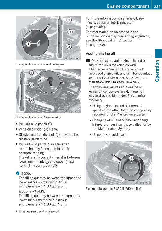
Example illustration: Gasoline engine
Example illustration: Diesel engine
X Pull out oil dipstick :.X Wipe oil dipstick : clean.X Slowly insert oil dipstick : fully into the
dipstick guide tube.X Pull out oil dipstick : again after
approximately 3 seconds to obtainaccurate reading.The oil level is correct when it is betweenlower (min) mark = and upper (max)mark ; of oil dipstick :.
i E 350:The filling quantity between the upper andlower marks on the oil dipstick isapproximately 2.1 US qt. (2.0 l).E 550, E 63 AMG:The filling quantity between the upper andlower marks on the oil dipstick isapproximately 1.6 US qt. (1.5 l).
X If necessary, add engine oil.
For more information on engine oil, see“Fuels, coolants, lubricants etc.”(Y page 359).For information on messages in themultifunction display concerning engine oil,see the “Practical hints” section(Y page 298).
Adding engine oil ! Only use approved engine oils and oil
filters required for vehicles withMaintenance System. For a listing ofapproved engine oils and oil filters, contactan authorized Mercedes-Benz Center orvisit www.mbusa.com (USA only).The following will result in engine oremission control system damage notcovered by the Mercedes-Benz LimitedWarranty:RUsing engine oils and oil filters of
specification other than those expresslyrequired for the Maintenance System.RChanging of oil and oil filter at change
intervals longer than those called for bythe Maintenance System.RUsing any oil additives.
Example illustration: E 350 (E 550 similar)
Engine compartment 225
Oper
atio
n
212_AKB; 2; 41, en-USd2ureepe, Version: 2.11.8.1
2009-07-17T09:14:21+02:00 - Seite 225
Z
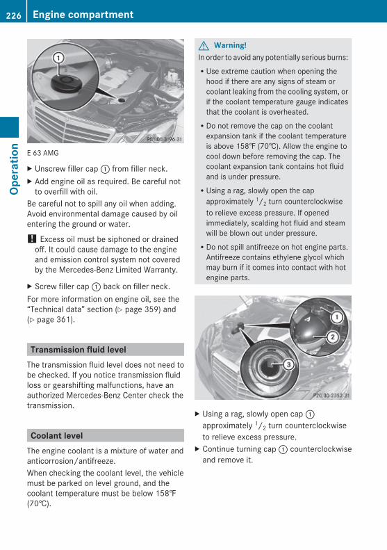
E 63 AMG
X Unscrew filler cap : from filler neck.X Add engine oil as required. Be careful not
to overfill with oil.Be careful not to spill any oil when adding.Avoid environmental damage caused by oilentering the ground or water.
! Excess oil must be siphoned or drainedoff. It could cause damage to the engineand emission control system not coveredby the Mercedes-Benz Limited Warranty.
X Screw filler cap : back on filler neck.For more information on engine oil, see the“Technical data” section (Y page 359) and(Y page 361).
Transmission fluid levelThe transmission fluid level does not need tobe checked. If you notice transmission fluidloss or gearshifting malfunctions, have anauthorized Mercedes-Benz Center check thetransmission.
Coolant levelThe engine coolant is a mixture of water andanticorrosion/antifreeze.When checking the coolant level, the vehiclemust be parked on level ground, and thecoolant temperature must be below 158‡(70†).
G Warning!In order to avoid any potentially serious burns:RUse extreme caution when opening the
hood if there are any signs of steam orcoolant leaking from the cooling system, orif the coolant temperature gauge indicatesthat the coolant is overheated.RDo not remove the cap on the coolant
expansion tank if the coolant temperatureis above 158‡ (70†). Allow the engine tocool down before removing the cap. Thecoolant expansion tank contains hot fluidand is under pressure.RUsing a rag, slowly open the cap
approximately 1/2 turn counterclockwiseto relieve excess pressure. If openedimmediately, scalding hot fluid and steamwill be blown out under pressure.RDo not spill antifreeze on hot engine parts.
Antifreeze contains ethylene glycol whichmay burn if it comes into contact with hotengine parts.
X Using a rag, slowly open cap :approximately 1/2 turn counterclockwiseto relieve excess pressure.
X Continue turning cap : counterclockwiseand remove it.
226 Engine compartmentOp
erat
ion
212_AKB; 2; 41, en-USd2ureepe, Version: 2.11.8.1
2009-07-17T09:14:21+02:00 - Seite 226

The coolant level is correct if the levelRfor cold coolant: reaches marking bar= in coolant expansion tank ;Rfor warm coolant: is approximately 0.6 in
(1.5 cm) higherX Add coolant as required.X Screw cap : back on and tighten it.For more information on coolant, see the“Technical data” section (Y page 361) and(Y page 365).
Washer system and headlamp cleaning system
G Warning!Washer solvent/antifreeze is highlyflammable. Do not spill washer solvent/antifreeze on hot engine parts, because it mayignite and burn. You could be seriouslyburned.
! Always use washer solvent/antifreezewhere temperatures may fall belowfreezing point. Failure to do so could resultin damage to the washer system/fluidreservoir.
! Only use washer fluid which is suitable forplastic lenses. Improper washer fluid candamage the plastic lenses of theheadlamps.
! Do not use distilled or deionized water inthe washer fluid reservoir. Otherwise, thewasher fluid level sensor could bedamaged.
Fluid for the washer system and the headlampcleaning system is supplied from the washerfluid reservoir.During all seasons, use MB WindshieldWasher Concentrate “MB SummerFit”. Mix itwith water or premixed washer solvent/antifreeze depending on the ambienttemperature (Y page 367).
X Opening washer fluid reservoir: Pull tabof cap : upwards.
X Refill the washer fluid reservoir.X Closing washer fluid reservoir: Press
cap : onto filler hole until it engages.For more information, see “Washer systemand headlamp cleaning system”(Y page 361).
Brake fluid level! If you find that the brake fluid in the brake
fluid reservoir has fallen to the minimummark or below, have the brake systemchecked for brake pad thickness and leaksimmediately. Contact an authorizedMercedes-Benz Center immediately. Donot add brake fluid as this will not solve theproblem. For more information, see“Practical hints”.
When checking the brake fluid level, thevehicle must be parked on level ground.
Engine compartment 227
Oper
atio
n
212_AKB; 2; 41, en-USd2ureepe, Version: 2.11.8.1
2009-07-17T09:14:21+02:00 - Seite 227
Z

The brake fluid level is correct when it isbetween lower mark (MIN) ; and uppermark (MAX) : of the brake fluid reservoir.
Tires and wheels
Safety notesContact an authorized Mercedes-Benz Centerfor information on tested and recommendedrims and tires for summer and winteroperation. They can also offer adviceconcerning tire service and purchase.
G Warning!Replace rims or tires with the samedesignation, manufacturer and type as shownon the original part. For further informationcontact an authorized Mercedes-Benz Center.If incorrectly sized rims and tires aremounted, the wheel brakes or suspensioncomponents can be damaged. Also, theoperating clearance of the wheels and thetires may no longer be correct.
G Warning!Worn, old tires can cause accidents. If the tiretread is worn to minimum tread depth, or ifthe tires have sustained damage, replacethem.When replacing rims, only use genuineMercedes-Benz wheel bolts specified for theparticular rim type. Failure to do so can resultin the bolts loosening and possibly anaccident.Retreaded tires are not tested orrecommended by Mercedes-Benz, sinceprevious damage cannot always berecognized on retreads. The operating safetyof the vehicle cannot be assured when suchtires are used.
G Warning!If you feel a sudden significant vibration orride disturbance, or you suspect that possibledamage to your vehicle has occurred, you
should turn on the hazard warning flashers,carefully slow down, and drive with caution toan area which is a safe distance from the road.Inspect the tires and the vehicle underbodyfor possible damage. If the vehicle or tiresappear unsafe, have the vehicle towed to thenearest authorized Mercedes-Benz Center ortire dealer for repairs.
G Warning!Do not drive with a flat tire. A flat tire affectsthe ability to steer or brake the vehicle. Youcould lose control of the vehicle. Continueddriving with a flat tire or driving at high speedwith a flat tire will cause excessive heat build-up and possibly a fire.
Important guidelinesROnly use sets of tires and rims of the same
type and make.RTires must be of the correct size for the rim.RBreak in new tires for approximately
60 miles (100 km) at moderate speeds.RRegularly check the tires and rims for
damage. Dented or bent rims can cause tireinflation pressure loss and damage to thetire beads.RIf the vehicle is heavily loaded, check tire
inflation pressure and correct as required.RDo not allow your tires to wear down too
far. Adhesion properties on wet roads aresharply reduced at tread depths of lessthan 1/8 in (3 mm).RWhen replacing individual tires, you should
mount new tires on the front wheels first(on vehicles with same-sized wheels allaround).
228 Tires and wheelsOp
erat
ion
212_AKB; 2; 41, en-USd2ureepe, Version: 2.11.8.1
2009-07-17T09:14:21+02:00 - Seite 228

Recommended tire inflation pressure
G Warning!Follow recommended tire inflation pressures.Do not underinflate tires. Underinflated tireswear excessively and/or unevenly, adverselyaffect handling and fuel economy, and aremore likely to fail from being overheated.Do not overinflate tires. Overinflated tires canadversely affect handling and ride comfort,wear unevenly, increase stopping distance,and result in sudden deflation (blowout)because they are more likely to becomepunctured or damaged by road debris,potholes etc.Do not overload the tires by exceeding thespecified load limit as indicated on the Tireand Loading Information placard on thedriver’s door B-pillar. Overloading the tirescan overheat them, possibly causing ablowout. Overloading the tires can also resultin handling or steering problems, or brakefailure.
Your vehicle is equipped with the Tire andLoading Information placard located on thedriver’s door B-pillar (Y page 237).The tire inflation pressure should be checkedregularly. Only adjust the tire inflationpressure on cold tires. The tires can beconsidered cold if the vehicle has beenparked for at least 3 hours or driven less than1 mile (1.6 km). Depending on the ambienttemperature, the driving speed and the tireload, the tire temperature changes. When thetire temperature changes by 18‡ (10†), thetire inflation pressure will change byapproximately 1.5 psi (0.1 bar). Keep this inmind when checking tire inflation pressure onwarm tires and adjust the tire pressure onlyif the tire inflation pressure is too low for thecurrent operating conditions. If you check thetire inflation pressure when the tires arewarm, the reading will be higher than the coldreading. This is normal. Do not let air out tomatch the specified cold tire inflation
pressure. Otherwise, the tire will beunderinflated.Follow recommended cold tire inflationpressures listed on Tire and LoadingInformation placard on the driver’s doorB-pillar.Keeping the tires properly inflated providesthe best handling, tread life and ridingcomfort.In addition to the Tire and LoadingInformation placard on the driver’s doorB-pillar, also consult the tire inflationpressure label on the inside of the filler flapfor any additional information pertaining tospecial driving situations. For moreinformation, see “Important notes on tireinflation pressure” (Y page 230).
i Data shown on Tire and LoadingInformation placard example are forillustration purposes only. Tire data arespecific to each vehicle and may vary fromdata shown in the following illustration.Refer to Tire and Loading Informationplacard on vehicle for actual data specificto your vehicle.
The Tire and Loading Information placard liststhe recommended cold tire inflationpressures : for maximum loaded vehicleweight. The tire inflation pressures listedapply to the tires installed as originalequipment.
Tires and wheels 229
Oper
atio
n
212_AKB; 2; 41, en-USd2ureepe, Version: 2.11.8.1
2009-07-17T09:14:21+02:00 - Seite 229
Z
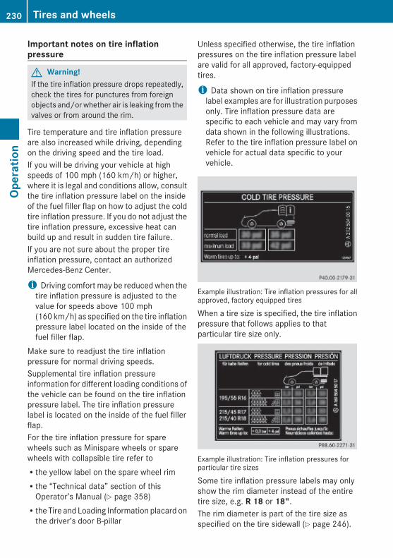
Important notes on tire inflation pressure
G Warning!If the tire inflation pressure drops repeatedly,check the tires for punctures from foreignobjects and/or whether air is leaking from thevalves or from around the rim.
Tire temperature and tire inflation pressureare also increased while driving, dependingon the driving speed and the tire load.If you will be driving your vehicle at highspeeds of 100 mph (160 km/h) or higher,where it is legal and conditions allow, consultthe tire inflation pressure label on the insideof the fuel filler flap on how to adjust the coldtire inflation pressure. If you do not adjust thetire inflation pressure, excessive heat canbuild up and result in sudden tire failure.If you are not sure about the proper tireinflation pressure, contact an authorizedMercedes-Benz Center.
i Driving comfort may be reduced when thetire inflation pressure is adjusted to thevalue for speeds above 100 mph(160 km/h) as specified on the tire inflationpressure label located on the inside of thefuel filler flap.
Make sure to readjust the tire inflationpressure for normal driving speeds.Supplemental tire inflation pressureinformation for different loading conditions ofthe vehicle can be found on the tire inflationpressure label. The tire inflation pressurelabel is located on the inside of the fuel fillerflap.For the tire inflation pressure for sparewheels such as Minispare wheels or sparewheels with collapsible tire refer toRthe yellow label on the spare wheel rimRthe “Technical data” section of this
Operator’s Manual (Y page 358)Rthe Tire and Loading Information placard on
the driver’s door B-pillar
Unless specified otherwise, the tire inflationpressures on the tire inflation pressure labelare valid for all approved, factory-equippedtires.
i Data shown on tire inflation pressurelabel examples are for illustration purposesonly. Tire inflation pressure data arespecific to each vehicle and may vary fromdata shown in the following illustrations.Refer to the tire inflation pressure label onvehicle for actual data specific to yourvehicle.
Example illustration: Tire inflation pressures for allapproved, factory equipped tires
When a tire size is specified, the tire inflationpressure that follows applies to thatparticular tire size only.
Example illustration: Tire inflation pressures forparticular tire sizes
Some tire inflation pressure labels may onlyshow the rim diameter instead of the entiretire size, e.g. R 18 or 18".The rim diameter is part of the tire size asspecified on the tire sidewall (Y page 246).
230 Tires and wheelsOp
erat
ion
212_AKB; 2; 41, en-USd2ureepe, Version: 2.11.8.1
2009-07-17T09:14:21+02:00 - Seite 230
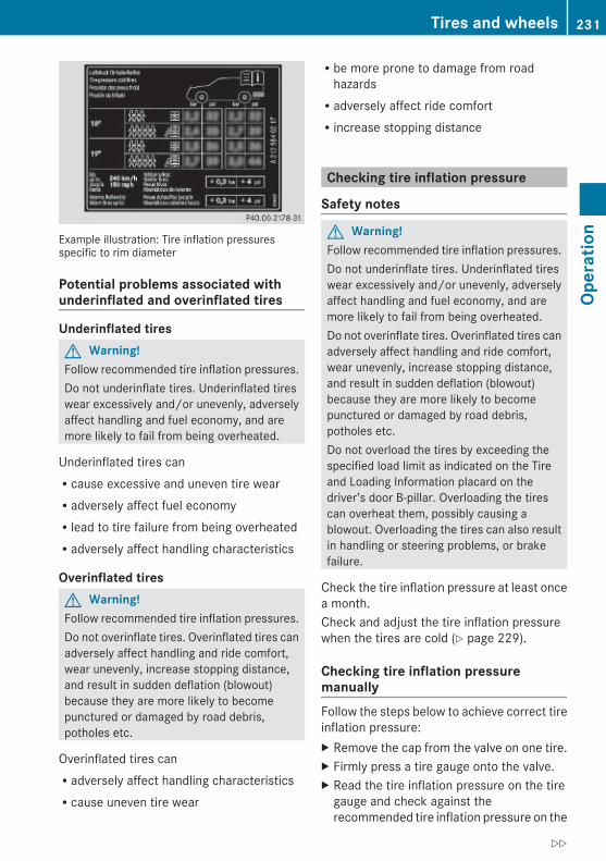
Example illustration: Tire inflation pressuresspecific to rim diameter
Potential problems associated with underinflated and overinflated tires
Underinflated tiresG Warning!Follow recommended tire inflation pressures.Do not underinflate tires. Underinflated tireswear excessively and/or unevenly, adverselyaffect handling and fuel economy, and aremore likely to fail from being overheated.
Underinflated tires canRcause excessive and uneven tire wearRadversely affect fuel economyRlead to tire failure from being overheatedRadversely affect handling characteristics
Overinflated tiresG Warning!Follow recommended tire inflation pressures.Do not overinflate tires. Overinflated tires canadversely affect handling and ride comfort,wear unevenly, increase stopping distance,and result in sudden deflation (blowout)because they are more likely to becomepunctured or damaged by road debris,potholes etc.
Overinflated tires canRadversely affect handling characteristicsRcause uneven tire wear
Rbe more prone to damage from roadhazardsRadversely affect ride comfortRincrease stopping distance
Checking tire inflation pressure
Safety notes
G Warning!Follow recommended tire inflation pressures.Do not underinflate tires. Underinflated tireswear excessively and/or unevenly, adverselyaffect handling and fuel economy, and aremore likely to fail from being overheated.Do not overinflate tires. Overinflated tires canadversely affect handling and ride comfort,wear unevenly, increase stopping distance,and result in sudden deflation (blowout)because they are more likely to becomepunctured or damaged by road debris,potholes etc.Do not overload the tires by exceeding thespecified load limit as indicated on the Tireand Loading Information placard on thedriver’s door B-pillar. Overloading the tirescan overheat them, possibly causing ablowout. Overloading the tires can also resultin handling or steering problems, or brakefailure.
Check the tire inflation pressure at least oncea month.Check and adjust the tire inflation pressurewhen the tires are cold (Y page 229).
Checking tire inflation pressure manuallyFollow the steps below to achieve correct tireinflation pressure:X Remove the cap from the valve on one tire.X Firmly press a tire gauge onto the valve.X Read the tire inflation pressure on the tire
gauge and check against therecommended tire inflation pressure on the
Tires and wheels 231
Oper
atio
n
212_AKB; 2; 41, en-USd2ureepe, Version: 2.11.8.1
2009-07-17T09:14:21+02:00 - Seite 231
Z

Tire and Loading Information placard on thedriver’s door B-pillar (Y page 237). Ifnecessary, add air to achieve therecommended tire inflation pressure.
X If you have overfilled the tire, release tireinflation pressure by pushing the metalstem of the valve with e.g. a tip of a pen.Then recheck the tire inflation pressurewith the tire gauge.
X Install the valve cap.X Repeat this procedure for each tire.
Tire pressure loss warning system (Canada only)While the vehicle is being driven, the tirepressure loss warning system monitors theset tire inflation pressures by evaluating eachwheel’s rotational speed. This allows thesystem to detect a significant loss of pressurein a tire. If a wheel’s rotational speed changesdue to falling tire inflation pressure, you willsee a corresponding warning message in themultifunction display.The tire pressure loss warning system mayfunction in a restricted manner or with a delayRwhen snow chains are mounted to the
vehicleRin the presence of ice and snowRwhen you are driving on a loose surface
(e.g. sand or gravel)Rwhen you are driving in a very sporty
manner (involving rapid acceleration orhigh speeds in curves)
G Warning!When the multifunction display shows themessage Check Tire Pressure Soon, oneor more of your tires are significantlyunderinflated. You should stop and checkyour tires as soon as possible, and inflatethem to the proper tire inflation pressure asindicated on the vehicle’s Tire and LoadingInformation placard or, if available, on the tireinflation pressure label.
Driving on a significantly underinflated tirecauses the tire to overheat and can lead totire failure. Underinflation also reduces fuelefficiency and tire tread life, and may affectthe vehicle’s handling and stopping ability.Each tire, including the spare, should bechecked at least once a month when cold.Inflate the tires to the recommended tireinflation pressure as specified onRthe Tire and Loading Information placard on
the driver’s door B-pillarorRthe tire inflation pressure label located on
the inside of the fuel filler flap
i The recommended tire inflation pressuresfor your vehicle can be found onRthe Tire and Loading Information placard
located on the driver’s door B-pillar(Y page 237)Rthe tire inflation pressure label on the
inside of the fuel filler flapThe tire inflation pressures are not listed inthe Operator’s Manual.
G Warning!The tire pressure loss warning system doesnot provide a warning for wrongly selected tireinflation pressures. Always adjust tireinflation pressure according to the Tire andLoading Information placard on the driver’sdoor B-pillar or on the tire inflation pressurelabel located on the inside of the fuel filler flap.The tire pressure loss warning system doesnot replace regular checks of the tire inflationpressures since a gradual pressure loss inmore than one tire cannot be detected by thetire pressure loss warning system.The tire pressure loss warning system is notable to issue a warning due to a suddendramatic loss of tire inflation pressure (e.g.tire blowout caused by a foreign object). Inthis case bring the vehicle to a halt by carefully
232 Tires and wheelsOp
erat
ion
212_AKB; 2; 41, en-USd2ureepe, Version: 2.11.8.1
2009-07-17T09:14:21+02:00 - Seite 232
applying the brakes and avoiding abruptsteering maneuvers.
Restarting the tire pressure loss warning systemThe tire pressure loss warning system mustbe restarted in the following situations:Rafter you have changed the tire inflation
pressureRafter you have replaced the wheels or tiresRafter you have installed new wheels or tiresX Using the Tire and Loading Information
placard on the driver’s door B-pillar or, ifavailable, the tire inflation pressure label onthe inside of the fuel filler flap, make surethe tire inflation pressure of all four tires iscorrect.
G Warning!The tire pressure loss warning system canonly warn you in a reliable manner if you haveset the correct tire inflation pressures foreach tire.If an incorrect tire inflation pressure was set,the system will monitor the pressureaccording to the incorrect value.
X Switch on the ignition.X Press button = or ; on the
multifunction steering wheel to select theServ. menu (Y page 138).
X Press button 9 or : on themultifunction steering wheel to selectTire Pressure.
X Press button a on the multifunctionsteering wheel to confirm.The following message appears in themultifunction display:Run Flat IndicatorActivePress 'OK' to Restart
X Press button a.The following message will appear in themultifunction display:Tire Pressure
Now OK?CancelYes
X If you wish to confirm: Press button9 or : to select Yes.
X Press button a.The following message will appear in themultifunction display:Run FlatIndicatorRestartedAfter a certain “learning phase”, the tirepressure loss warning system checks theset pressure values for all four tires.
X If you wish to cancel: Press button 9or : to select Cancel.
X Press button a to confirm.The previous settings remain unchanged.
Advanced Tire Pressure Monitoring System (Advanced TPMS)Your vehicle is equipped with the AdvancedTire Pressure Monitoring System (AdvancedTPMS). It measures the tire inflation pressurein the vehicle’s tires and issues warnings incase of pressure loss in one or more of thetires.The TPMS is equipped with a combination lowtire pressure/TPMS malfunction telltale(USA) or a low tire pressure telltale (Canada)in the instrument cluster. Depending on howthe telltale illuminates, it indicates a low tirepressure condition or a malfunction in theTPMS system itself:RIf the telltale illuminates continuously, one
or more of your tires is significantlyunderinflated. There is no malfunction inthe TPMS.RUSA only: If the telltale flashes for 60
seconds and then stays illuminated, theTPMS system itself is not operatingproperly.
The TPMS only functions on wheels that areequipped with the proper electronic sensors.
Tires and wheels 233
Oper
atio
n
212_AKB; 2; 41, en-USd2ureepe, Version: 2.11.8.1
2009-07-17T09:14:21+02:00 - Seite 233
Z

G Warning!The TPMS does not indicate a warning forwrongly selected inflation pressures. Alwaysadjust tire inflation pressure according to theTire and Loading Information placard or thesupplemental tire inflation pressureinformation on the inside of the fuel filler flap.The TPMS is not able to issue a warning dueto a sudden dramatic loss of pressure (e.g. tireblowout caused by a foreign object). In thiscase bring the vehicle to a halt by carefullyapplying the brakes and avoiding abruptsteering maneuvers.
G Warning!Each tire, including the spare (if provided),should be checked at least once a monthwhen cold and inflated to the inflationpressure recommended by the vehiclemanufacturer on the Tire and LoadingInformation placard on the driver’s door B-pillar or the tire inflation pressure label on theinside of the fuel filler flap. If your vehicle hastires of a different size than the size indicatedon the Tire and Loading Information placardor the tire inflation pressure label, you shoulddetermine the proper tire inflation pressurefor those tires.As an added safety feature, your vehicle hasbeen equipped with a tire pressure monitoringsystem (TPMS) that illuminates a low tirepressure telltale when one or more of yourtires are significantly underinflated.Accordingly, when the low tire pressuretelltale illuminates, you should stop and checkyour tires as soon as possible, and inflatethem to the proper pressure. Driving on asignificantly underinflated tire causes the tireto overheat and can lead to tire failure.Underinflation also reduces fuel efficiencyand tire tread life, and may affect the vehicle’shandling and stopping ability. Please note thatthe TPMS is not a substitute for proper tiremaintenance, and it is the driver’sresponsibility to maintain correct tirepressure, even if underinflation has not
reached the level to trigger illumination of theTPMS low tire pressure telltale.USA only:Your vehicle has also been equipped with aTPMS malfunction indicator to indicate whenthe system is not operating properly. TheTPMS malfunction indicator is combined withthe low tire pressure telltale. When thesystem detects a malfunction, the telltale willflash for approximately 1 minute and thenremain continuously illuminated. Thissequence will continue upon subsequentvehicle start-ups as long as the malfunctionexists. When the malfunction indicator isilluminated, the system may not be able todetect or signal low tire pressure as intended.TPMS malfunctions may occur for a variety ofreasons, including the installation ofincompatible replacement or alternate tiresor wheels on the vehicle that prevent theTPMS from functioning properly. Alwayscheck the TPMS malfunction telltale afterreplacing one or more tires or wheels on yourvehicle to ensure that the replacement oralternate tires and wheels allow the TPMS tocontinue to function properly.
i USA only:If a condition causing the TPMS tomalfunction develops, it may take up to10 minutes for the system to signal amalfunction using the TPMS telltaleflashing and illumination sequence.The telltale extinguishes after a fewminutes driving if the malfunction has beencorrected.
Tire pressure inquiries are made using themultifunction display. The current tireinflation pressure for each tire appears in themultifunction display after a few minutes ofdriving.
i Possible differences between thereadings of a tire pressure gauge of an airhose, e.g. gas station equipment, and thevehicle’s control system can occur. The tire
234 Tires and wheelsOp
erat
ion
212_AKB; 2; 41, en-USd2ureepe, Version: 2.11.8.1
2009-07-17T09:14:21+02:00 - Seite 234

pressure displayed by the control systemapply to sea level. In high-altitudelocations, the reading on a tire pressuregauge will be higher than the reading issuedby the vehicle’s control system. Do notreduce the tire inflation pressure undersuch circumstances.
X Switch on the ignition.X Press button = or ; on the
multifunction steering wheel to select theServ. menu (Y page 138).
X Press button 9 or : to select Tire Pressure.
X Press button a.The current inflation pressure for each tireappears in the multifunction display.
Example illustration
When the vehicle has been parked for longerthan 20 minutes, the message Tire pressures will be displayed after driving a few minutes appears in themultifunction display.The TPMS recognizes new wheels or sensorsautomatically after the learn-in phase. As longas the tire inflation pressure values cannot beallocated to the individual wheels, themessage Tire Pressure Monitor Activeappears. Despite this message, the tireinflation pressure values are monitoredalready.
i With a spare wheel mounted, the systemmay still indicate the tire inflation pressureof the removed road wheel for someminutes. If this happens, keep in mind thatthe indicated value where the spare wheelis mounted does not reflect the actualspare tire inflation pressure.
i Operating radio transmission equipment(e.g. wireless headsets, two-way radios) inor near the vehicle could cause the TPMSto malfunction.
i USA only:This device complies with Part 15 of theFCC Rules. Operation is subject to thefollowing two conditions:1. This device may not cause harmful
interference, and2. this device must accept any
interference received, includinginterference that may cause undesired.
Any unauthorized modification to thisdevice could void the user’s authority tooperate the equipment.
i Canada only:This device complies with RSS-210 ofIndustry Canada. Operation is subject tothe following two conditions:1. This device may not cause interference,
and2. this device must accept any
interference received, includinginterference that may cause undesiredoperation of the device.
Any unauthorized modification to thisdevice could void the user’s authority tooperate the equipment.
Tire inflation pressure warningsIf the system detects a significant loss of tireinflation pressure in one or more than onetire, a message appears in the multifunctiondisplay. In addition, an acoustic warningsounds and the low tire pressure telltale in theinstrument cluster comes on.
Tires and wheels 235
Oper
atio
n
212_AKB; 2; 41, en-USd2ureepe, Version: 2.11.8.1
2009-07-17T09:14:21+02:00 - Seite 235
Z

Example illustration
The respective tire is indicated by a redrectangle.
Restarting Advanced TPMSG Warning!It is the driver’s responsibility to set the tireinflation pressure to the recommended coldtire inflation pressure. Underinflated tiresaffect the ability to steer or brake the vehicle.You might lose control over the vehicle.
When you restart the TPMS, the system setsnew reference values for each tire.The TPMS must be restarted when you haveadjusted the tire inflation pressure to a newlevel (e.g. because of different load or drivingconditions). The TPMS is then recalibrated tothe current tire inflation pressures.
i Canada only:The TPMS usually recognizes tire pressureadjustments and sets new reference valuesautomatically. You can, however, restartthe TPMS manually as described.
Restart the TPMS after adjusting the tireinflation pressure to the inflation pressurerecommended for the vehicle operatingcondition. Tire inflation pressure should onlybe adjusted on cold tires. Observe therecommended tire inflation pressure on theTire and Loading Information placard on thedriver’s door B-pillar. Some vehicles may havesupplemental tire inflation pressureinformation for driving at high speeds or forvehicle loads less than the maximum loadedvehicle condition. If such information isprovided, it can be found on the inside of thefuel filler flap.
X Using the Tire and Loading Informationplacard on the driver’s door B-pillar(Y page 237) or the supplemental tireinflation pressure information on the insideof the fuel filler flap, make sure the tireinflation pressure of all four tires is correct.
X Switch on the ignition.X Press button = or ; on the
multifunction steering wheel to select theServ. menu.
X Press button 9 or : on themultifunction steering wheel to selectTire Pressure.
X Press button a.The current inflation pressure for each tireappears in the multifunction display or thefollowing message appears in themultifunction display:Tire pressureswill be displayedafter drivinga few minutes
X Press button :.The following message appears in themultifunction display:Use CurrentPressures As NewReference ValuesPress 'OK' to Confirm
X Press button a.The following message appears in themultifunction display:Tire Press. MonitorRestartedAfter driving a few minutes the systemverifies that the current tire inflationpressures are within the system’s specifiedrange. Afterwards the current tire inflationpressures are accepted as reference valuesand then monitored.
X If you wish to cancel: Press button %.orX Press button 9 to exit the menu screen.
i When the wheel positions have beenchanged, the inflation pressure of a tire
236 Tires and wheelsOp
erat
ion
212_AKB; 2; 41, en-USd2ureepe, Version: 2.11.8.1
2009-07-17T09:14:21+02:00 - Seite 236

may be displayed for the wrong positiontemporarily. After driving for a few minutes,the inflation pressure will be shown for thecorrect position.
Maximum tire inflation pressure
G Warning!Never exceed the maximum tire inflationpressure. Follow recommended tire inflationpressures.Do not underinflate tires. Underinflated tireswear excessively and/or unevenly, adverselyaffect handling and fuel economy, and aremore likely to fail from being overheated.Do not overinflate tires. Overinflated tires canadversely affect handling and ride comfort,wear unevenly, increase stopping distance,and result in sudden deflation (blowout)because they are more likely to becomepunctured or damaged by road debris,potholes etc.
i For illustration purposes only. Actual dataon tires are specific to each vehicle andmay vary from data shown in aboveillustration.
This is the maximum permissible tire inflationpressure : for the tire.Always follow the recommended tire inflationpressure (Y page 229) for proper tireinflation.
Loading the vehicleTwo labels on your vehicle show how muchweight it may properly carry.(1) The Tire and Loading Information placard
can be found on the driver’s doorB-pillar. This placard tells you importantinformation about the number of peoplethat can be in the vehicle and the totalweight that can be carried in the vehicle.It also contains information on the propersize and recommended tire inflationpressures for the original equipment tireson your vehicle.
(2) The certification label, also found on thedriver’s door B-pillar. It tells you about thegross weight capacity of your vehicle,called the Gross Vehicle Weight Rating(GVWR). The GVWR includes the weightof the vehicle, all occupants, fuel andcargo. The certification label also tellsyou about the front and rear axle weightcapacity, called the Gross Axle WeightRating (GAWR).The GAWR is the total allowable weightthat can be carried by a single axle (frontor rear). Never exceed the GVWR orGAWR for either the front axle or rearaxle.
: Driver’s door B-pillar
Following is a discussion on how to work withthe information contained on the Tire andLoading Information placard with regards toloading your vehicle.
Tires and wheels 237
Oper
atio
n
212_AKB; 2; 41, en-USd2ureepe, Version: 2.11.8.1
2009-07-17T09:14:21+02:00 - Seite 237
Z

Tire and Loading Information
G Warning!Do not overload the tires by exceeding thespecified load limit as indicated on the Tireand Loading Information placard on thedriver’s door B-pillar. Overloading the tirescan overheat them, possibly causing ablowout. Overloading the tires can also resultin handling or steering problems, or brakefailure.
Tire and Loading Information placardi Data shown on Tire and Loading
Information placard example are forillustration purposes only. Load limit dataare specific to each vehicle and may varyfrom data shown in the followingillustration. Refer to Tire and LoadingInformation placard on vehicle for actualdata specific to your vehicle.
The Tire and Loading Information placardshowing load limit information : is locatedon the driver’s door B-pillar (Y page 237).X Locate the statement “The combined
weight of occupants and cargo shouldnever exceed XXX kilograms or XXX lbs.”on the Tire and Loading Informationplacard.
The combined weight of all occupants,cargo/luggage and trailer tongue load (ifapplicable) should never exceed the weightreferenced in that statement.
Seating capacity i Data shown on Tire and Loading
Information placard example are forillustration purposes only. Seating capacitydata are specific to each vehicle and mayvary from data shown in the followingillustration. Refer to Tire and LoadingInformation placard on vehicle for actualdata specific to your vehicle.
The seating capacity gives you importantinformation on the number of occupants thatcan be in the vehicle. Observe front and rearseating capacity. The Tire and LoadingInformation placard showing seatingcapacity : is located on the driver’s doorB-pillar (Y page 237).
Steps for determining correct load limit The following steps have been developed asrequired of all manufacturers under Title 49,Code of U.S. Federal Regulations, Part 575pursuant to the “National Traffic and MotorVehicle Safety Act of 1966”.X Step 1: Locate the statement “The
combined weight of occupants and cargoshould never exceed XXX kg or XXX lbs.”on your vehicle’s Tire and LoadingInformation placard.
X Step 2: Determine the combined weight ofthe driver and passengers that will be ridingin your vehicle.
X Step 3: Subtract the combined weight ofthe driver and passengers fromXXX kilograms or XXX lbs.
238 Tires and wheelsOp
erat
ion
212_AKB; 2; 41, en-USd2ureepe, Version: 2.11.8.1
2009-07-17T09:14:21+02:00 - Seite 238

X Step 4: The resulting figure equals theavailable amount of cargo and luggage loadcapacity. For example, if the “XXX” amountequals 1 400 lbs and there will be five150 lbs passengers in your vehicle, theamount of available cargo and luggage loadcapacity is 650 lbs(1 400 - 750 (5 x 150) = 650 lbs).
X Step 5: Determine the combined weight ofluggage and cargo being loaded on thevehicle. That weight may not safely exceedthe available cargo and luggage loadcapacity calculated in step 4.
X Step 6 (if applicable): If your vehicle willbe towing a trailer, load from your trailerwill be transferred to your vehicle. Consultthis manual to determine how this reducesthe available cargo and luggage loadcapacity of your vehicle (Y page 241).
The following table shows examples on howto calculate total and cargo load capacitieswith varying seating configurations andnumber and size of occupants. The followingexamples use a load limit of 1 500 lbs. This is for illustration purposes only. Make sureyou are using the actual load limit for yourvehicle stated on the vehicle’s Tire andLoading Information placard (Y page 238).
Tires and wheels 239
Oper
atio
n
212_AKB; 2; 41, en-USd2ureepe, Version: 2.11.8.1
2009-07-17T09:14:21+02:00 - Seite 239
Z

Example 1 Example 2 Example 3
Step 1 Combined weight limit of occupants and cargo from Tire and Loading Information placard
1 500 lbs 1 500 lbs 1 500 lbs
Example 1 Example 2 Example 3
Step 2 Number of occupants (driver and passengers)
5 3 1
Seating configuration front: 2rear: 3
front: 1rear: 2
front: 1
Occupants weight Occupant 1:150 lbsOccupant 2:180 lbsOccupant 3:160 lbsOccupant 4:140 lbsOccupant 5:120 lbs
Occupant 1:200 lbsOccupant 2:190 lbsOccupant 3:150 lbs
Occupant 1:150 lbs
Combined weight of all occupants
750 lbs 540 lbs 150 lbs
Example 1 Example 2 Example 3
Step 3 Available cargo/luggage and trailer tongue weight (total load limit from Tire and Loading Information placard minus combined weight of all occupants)
1 500 lbs -750 lbs =750 lbs
1 500 lbs -540 lbs =960 lbs
1 500 lbs -150 lbs =1 350 lbs
The higher the weight of all occupants, theless cargo and luggage load capacity isavailable.For more information, see “Trailer tongueload” (Y page 241).
Certification labelEven after careful determination of thecombined weight of all occupants, cargo andthe trailer tongue load (if applicable)(Y page 241) as to not exceed thepermissible load limit, you must make sureyour vehicle never exceeds the Gross Vehicle
240 Tires and wheelsOp
erat
ion
212_AKB; 2; 41, en-USd2ureepe, Version: 2.11.8.1
2009-07-17T09:14:21+02:00 - Seite 240

Weight Rating (GVWR) and the Gross AxleWeight Rating (GAWR) for either the front orrear axle. You can obtain the GVWR andGAWR from the certification label. Thecertification label can be found on the driver’sdoor B-pillar, see the “Technical data” section(Y page 346).Gross Vehicle Weight Rating (GVWR): Thetotal weight of the vehicle, all occupants, allcargo, and the trailer tongue load (ifapplicable) must never exceed the GVWR.Gross Axle Weight Rating (GAWR): The totalallowable weight that can be carried by asingle axle (front or rear).To assure that your vehicle does not exceedthe maximum permissible weight limits(GVWR and GAWR for front and rear axle),have the loaded vehicle (including driver,passengers and all cargo and, if applicable,trailer fully loaded) weighed on a suitablecommercial scale.
Trailer tongue loadThe tongue load of any trailer is an importantweight to measure because it affects the loadyou can carry in your vehicle. If a trailer istowed, the tongue load must be added to theweight of all occupants riding and any cargoyou are carrying in the vehicle. The tongueload typically is 10% of the trailer weight andeverything loaded in it.Your Mercedes-Benz has been designedprimarily to carry passengers and their cargo.Mercedes-Benz does not recommend trailertowing with your vehicle.
Maximum tire load
G Warning!Do not overload the tires by exceeding thespecified load limit as indicated on the Tireand Loading Information placard on thedriver’s door B-pillar. Overloading the tirescan overheat them, possibly causing ablowout. Overloading the tires can also result
in handling or steering problems, or brakefailure.
i For illustration purposes only. Actual dataon tires are specific to each vehicle andmay vary from data shown in aboveillustration.
The maximum tire load rating : is themaximum weight the tires are designed tosupport.For more information on tire load rating, see(Y page 246).For information on calculating total and cargoload capacities, see (Y page 238).
Direction of rotationUnidirectional tires offer added advantages,such as better hydroplaning performance. Tobenefit, however, you must make sure thetires rotate in the direction specified.An arrow on the sidewall indicates theintended direction of rotation of the tire.Spare wheels may be mounted against thedirection of rotation (spinning) even with aunidirectional tire for temporary use only untilthe regular drive wheel has been repaired orreplaced. Always observe and followapplicable temporary use restrictions andspeed limitations indicated on the sparewheel.
Tires and wheels 241
Oper
atio
n
212_AKB; 2; 41, en-USd2ureepe, Version: 2.11.8.1
2009-07-17T09:14:21+02:00 - Seite 241
Z

MOExtended systemThe MOExtended system allows you tocontinue driving your vehicle even if there isa total loss of pressure in one or more tires.You may only use the MOExtended system inconjunction with the tire pressure losswarning system (Y page 232) or theAdvanced TPMS (Y page 233).
i Vehicles with MOExtended system arenot factory-equipped with a TIREFIT kit.When retrofitting with tires that do not haverun-flat characteristics, e.g. winter tires,you should also equip your vehicle with aTIREFIT kit. TIREFIT kits are available at anyauthorized Mercedes-Benz Center.
For information on driving in case of pressureloss in one or more tires (emergency mode),see the “Practical hints” section(Y page 329).
Tire care and maintenance
G Warning!Regularly check the tires for damage.Damaged tires can cause tire inflationpressure loss. As a result, you could losecontrol of your vehicle.Worn, old tires can cause accidents. If the tiretread is worn to minimum tread depth, or ifthe tires have sustained damage, replacethem.
Check the tire inflation pressure at least oncea month. For more information on checkingtire inflation pressure, see “Recommendedtire inflation pressure” (Y page 229).
Tire inspection Every time you check the tire inflationpressure, you should also inspect your tiresfor the following:Rexcessive treadwear (Y page 242)Rcord or fabric showing through the tire’s
rubberRbumps, bulges, cuts, cracks or splits in the
tread or side of the tireReplace the tire if you find any of the aboveconditions.Make sure you also inspect the spare tireperiodically for condition and inflation. Sparetires will age and become worn over time evenif never used, and thus should be inspectedand replaced when necessary.
Life of tire
G Warning!Tires and spare tire should be replaced after6 years, regardless of the remaining tread.
The service life of a tire is dependent uponvarying factors including but not limited to:RDriving styleRTire inflation pressureRDistance driven
Tread depth
G Warning!Although the applicable federal motor vehiclesafety laws consider a tire to be worn whenthe treadwear indicators (TWI) become visibleat approximately 1/16 in (1.6 mm), werecommend that you do not allow your tiresto wear down to that level. As tread depthapproaches 1/8 in (3 mm), the adhesionproperties on a wet road are sharply reduced.Depending upon the weather and/or roadsurface (conditions), the tire traction varieswidely.
242 Tires and wheelsOp
erat
ion
212_AKB; 2; 41, en-USd2ureepe, Version: 2.11.8.1
2009-07-17T09:14:21+02:00 - Seite 242
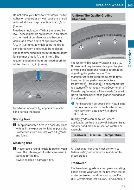
Do not allow your tires to wear down too far.Adhesion properties on wet roads are sharplyreduced at tread depths of less than 1/8 in(3 mm).Treadwear indicators (TWI) are required bylaw. These indicators are located in six placeson the tread circumference and becomevisible at a tread depth of approximately1/16 in (1.6 mm), at which point the tire isconsidered worn and should be replaced.The recommended minimum tire tread depthfor summer tires is 1/8 in (3 mm). Therecommended minimum tire tread depth forwinter tires is 1/6 in (4 mm).
Treadwear indicator : appears as a solidband across the tread.
Storing tires ! Keep unmounted tires in a cool, dry place
with as little exposure to light as possible.Protect tires from contact with oil, greaseand fuels.
Cleaning tires ! Never use a round nozzle to power wash
tires. The intense jet of water can result indamage to the tire.Always replace a damaged tire.
Uniform Tire Quality Grading Standards
The Uniform Tire Quality Grading is a U.S.Government requirement designed to givedrivers consistent and reliable informationregarding tire performance. Tiremanufacturers are required to grade tiresbased on three performance factors:treadwear :, traction ;, and temperatureresistance =. Although not a Government ofCanada requirement, all tires made for sale inNorth America have these grades branded onthe sidewall.
i For illustration purposes only. Actual dataon tires are specific to each vehicle andmay vary from data shown in aboveillustration.
Quality grades can be found, whereapplicable, on the tire sidewall between treadshoulder and maximum section width. Forexample:
Treadwear Traction Temperature
200 AA A
All passenger car tires must conform tofederal safety requirements in addition tothese grades.
Treadwear The treadwear grade is a comparative ratingbased on the wear rate of the tire when testedunder controlled conditions on a specifiedU.S. Government test course. For example, a
Tires and wheels 243
Oper
atio
n
212_AKB; 2; 41, en-USd2ureepe, Version: 2.11.8.1
2009-07-17T09:14:21+02:00 - Seite 243
Z

tire graded 150 would wear one and one-half(1 1/2) times as well on the governmentcourse as a tire graded 100.The relative performance of tires dependsupon the actual conditions of their use,however, and may depart significantly fromthe norm due to variations in driving habits,service practices and differences in roadcharacteristics and climate.
Traction
G Warning!The traction grade assigned to this tire isbased on straight-ahead braking tractiontests, and does not include acceleration,cornering, hydroplaning, or peak tractioncharacteristics.
The traction grades, from highest to lowest,are AA, A, B, and C. Those grades representthe tire’s ability to stop on wet pavement asmeasured under controlled conditions onspecified government test surfaces of asphaltand concrete. A tire marked C may have poortraction performance.
G Warning!If ice has formed on the road, tire traction willbe substantially reduced. Under such weatherconditions, drive, steer and brake withextreme caution.
The safe speed on a wet, snow covered or icyroad is always lower than on a dry road.You should pay particular attention to thecondition of the road whenever the outsidetemperature is close to the freezing point.Mercedes-Benz recommends winter tires(Y page 252) with a minimum tread depth ofapproximately 1/6 in (4 mm) on all four wheelsfor the winter season to ensure normalbalanced handling characteristics. Onpacked snow, they can reduce your stoppingdistance compared to summer tires.Stopping distance, however, is stillconsiderably greater than when the road is
not covered with snow or ice. Exerciseappropriate caution.
! Avoid spinning of a drive wheel. This maycause serious damage to the drivetrainwhich is not covered by the Mercedes-BenzLimited Warranty.
Temperature
G Warning!The temperature grade for this tire isestablished for a tire that is properly inflatedand not overloaded. Excessive speed,underinflation, or excessive loading, eitherseparately or in combination, can causeexcessive heat build-up and possible tirefailure.
The temperature grades are A (the highest),B, and C, representing the tire’s resistance tothe generation of heat and its ability todissipate heat when tested under controlledconditions on a specified indoor laboratorytest wheel. Sustained high temperature cancause the material of the tire to degenerateand reduce tire life, and excessivetemperature can lead to sudden tire failure.The grade C corresponds to a level ofperformance which all passenger car tiresmust meet under the Federal Motor VehicleSafety Standard No. 109. Grades B and Arepresent higher levels of performance on thelaboratory test wheel than the minimumrequired by law.
Rotating tires
G Warning!Rotate front and rear wheels only if the tiresare of the same dimension.If your vehicle is equipped with mixed-sizetires (different tire dimensions front vs. rear),tire rotation is not possible.
244 Tires and wheelsOp
erat
ion
212_AKB; 2; 41, en-USd2ureepe, Version: 2.11.8.1
2009-07-17T09:14:21+02:00 - Seite 244

G Warning!Have the tightening torque checked afterchanging a wheel. Wheels could becomeloose if not tightened with a torque of96 lb-ft (130 Nm).Only use genuine Mercedes-Benz wheel boltsspecified for your vehicle’s rims.
Tire rotation can be performed on vehicleswith tires of the same dimension all around.If your vehicle is equipped with tires of thesame dimension all around, tires can berotated, observing a front-to-rear rotationpattern that will maintain the intendedrotation (spinning) direction of the tire(Y page 241).In some cases, such as when your vehicle isequipped with mixed-size tires (different tiredimension front vs. rear), tire rotation is notpossible.If applicable to your vehicle’s tireconfiguration, tires can be rotated accordingto the tire manufacturer’s recommendedintervals in the tire manufacturer’s warrantypamphlet located in your vehicle literatureportfolio. If none is available, tires should berotated every 3 000 to 6 000 miles (5 000 to10 000 km), or sooner if necessary, accordingto the degree of tire wear. The same rotation(spinning) direction must be maintained.Rotate tires before the characteristic tirewear pattern becomes visible (shoulder wearon front tires and tread center wear on reartires).Thoroughly clean the mounting face of wheelsand brake disks, i.e. the inner side of thewheels/tires, during each rotation. Check forand ensure proper tire inflation pressure.For information on wheel change, see “Flattire” (Y page 323).
Tire labelingBesides tire name (sales designation) andmanufacturer name, a number of markingscan be found on a tire.
Following are some explanations for themarkings on your vehicle’s tires:
: Uniform Tire Quality Grading Standards(Y page 243)
; DOT, Tire Identification Number(Y page 248)
= Maximum tire load (Y page 241)? Maximum tire inflation pressure
(Y page 237)A ManufacturerB Tire ply material (Y page 249)C Tire size designation, load and speed
rating (Y page 246)D Load identification (Y page 248)E Tire name
i For illustration purposes only. Actual dataon tires are specific to each vehicle andmay vary from data shown in aboveillustration.For more information, see “Rims and tires”(Y page 353).
Tires and wheels 245
Oper
atio
n
212_AKB; 2; 41, en-USd2ureepe, Version: 2.11.8.1
2009-07-17T09:14:21+02:00 - Seite 245
Z
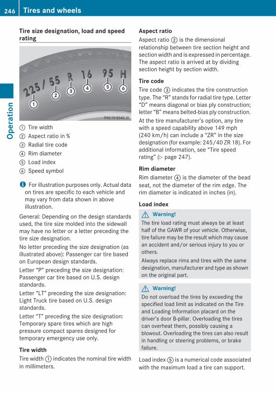
Tire size designation, load and speed rating
: Tire width; Aspect ratio in %= Radial tire code? Rim diameterA Load index B Speed symbol
i For illustration purposes only. Actual dataon tires are specific to each vehicle andmay vary from data shown in aboveillustration.
General: Depending on the design standardsused, the tire size molded into the sidewallmay have no letter or a letter preceding thetire size designation.No letter preceding the size designation (asillustrated above): Passenger car tire basedon European design standards.Letter “P” preceding the size designation:Passenger car tire based on U.S. designstandards.Letter “LT” preceding the size designation:Light Truck tire based on U.S. designstandards.Letter “T” preceding the size designation:Temporary spare tires which are highpressure compact spares designed fortemporary emergency use only.
Tire widthTire width : indicates the nominal tire widthin millimeters.
Aspect ratioAspect ratio ; is the dimensionalrelationship between tire section height andsection width and is expressed in percentage.The aspect ratio is arrived at by dividingsection height by section width.
Tire codeTire code = indicates the tire constructiontype. The “R” stands for radial tire type. Letter“D” means diagonal or bias ply construction;letter “B” means belted-bias ply construction.At the tire manufacturer’s option, any tirewith a speed capability above 149 mph(240 km/h) can include a “ZR” in the sizedesignation (for example: 245/40 ZR 18). Foradditional information, see “Tire speedrating” (Y page 247).
Rim diameterRim diameter ? is the diameter of the beadseat, not the diameter of the rim edge. Therim diameter is indicated in inches (in).
Load indexG Warning!The tire load rating must always be at leasthalf of the GAWR of your vehicle. Otherwise,tire failure may be the result which may causean accident and/or serious injury to you orothers.Always replace rims and tires with the samedesignation, manufacturer and type as shownon the original part.
G Warning!Do not overload the tires by exceeding thespecified load limit as indicated on the Tireand Loading Information placard on thedriver’s door B-pillar. Overloading the tirescan overheat them, possibly causing ablowout. Overloading the tires can also resultin handling or steering problems, or brakefailure.
Load index A is a numerical code associatedwith the maximum load a tire can support.
246 Tires and wheelsOp
erat
ion
212_AKB; 2; 41, en-USd2ureepe, Version: 2.11.8.1
2009-07-17T09:14:21+02:00 - Seite 246

For example, a load rating of 91 correspondsto a maximum load of 1356 lb (615 kg) thetire is designed to support. See also“Maximum tire load” (Y page 241) where themaximum load associated with the load indexis indicated in kilograms and lbs.For additional information on the load index,see “Load identification” (Y page 248).
Speed symbol G Warning!Even when permitted by law, never operate avehicle at speeds greater than the maximumspeed rating of the tires.Exceeding the maximum speed for which tiresare rated can lead to sudden tire failure,causing loss of vehicle control and possiblyresulting in an accident and/or seriouspersonal injury and possible death, for youand for others.
Regardless of the tire speed rating, localspeed limits should be obeyed. Use prudentdriving speeds appropriate to prevailingconditions.Speed symbol B indicates the approvedmaximum speed (tire speed rating) for thetire.Summer tires
Index Speed rating
Q up to 100 mph (160 km/h)
R up to 106 mph (170 km/h)
S up to 112 mph (180 km/h)
T up to 118 mph (190 km/h)
H up to 130 mph (210 km/h)
V up to 149 mph (240 km/h)
W up to 168 mph (270 km/h)
Y up to 186 mph (300 km/h)
ZR...Y up to 186 mph (300 km/h)
Index Speed rating
ZR...(..Y) above 186 mph (300 km/h)
ZR above 149 mph (240 km/h)
RAt the tire manufacturer’s option, any tirewith a speed capability above 149 mph(240 km/h) can include a “ZR” in the sizedesignation (for example: 245/40 ZR18).To determine the maximum speedcapability of the tire, the servicedescription for the tire must be referred to.The service description is comprised ofload index A and speed symbol B.If your tire includes “ZR” in the sizedesignation and no service description isgiven, the tire manufacturer must beconsulted for the maximum speedcapability.If a service description is given, the speedcapability is limited by the speed symbol inthe service description. Example:245/40 ZR18 97Y. In this example, “97Y”is the service description. The letter “Y”designates the speed rating and the speedcapability of the tire is limited to 186 mph(300 km/h).RAny tire with a speed capability above
186 mph (300 km/h) must include a “ZR”in the size designation AND the servicedescription must be placed in parenthesis.Example: 275/40 ZR 18 (99Y). The “(Y)”speed symbol in parenthesis designatesthe maximum speed capability of the tireas being above 186 mph (300 km/h).Consult the tire manufacturer for the actualmaximum permissible speed of the tire.
All-season and winter tires
Index Speed rating
Q M+S14 up to 100 mph (160 km/h)
T M+S14 up to 118 mph (190 km/h)
14 or M+Sifor winter tires
Tires and wheels 247
Oper
atio
n
212_AKB; 2; 41, en-USd2ureepe, Version: 2.11.8.1
2009-07-17T09:14:21+02:00 - Seite 247
Z

Index Speed rating
H M+S14 up to 130 mph (210 km/h)
V M+S14 up to 149 mph (240 km/h)
i Not all M+S rated tires provide specialwinter performance. Make sure the tiresyou use show M+S and the mountain/snowflakeimarking on the tiresidewall. These tires meet specific snowtraction performance requirements of theRubber Manufacturers Association (RMA)and the Rubber Association of Canada(RAC) and have been designed specificallyfor use in snow conditions.
An electronic speed limiter prevents yourvehicle from exceeding a speed of:RAll models except AMG vehicles:
130 mph (210 km/h)RE 63 AMG:
155 mph (250 km/h)RE 63 AMG (Performance Package):
186 mph (300 km/h)The factory equipped tires on your vehiclemay have a tire speed rating above themaximum speed permitted by the electronicspeed limiter.Make sure your tires have the required tirespeed rating as specified for your vehicle inthe “Technical data” section (Y page 353),for example when purchasing new tires.If you are uncertain about the correct readingof the information given on a tire’s sidewall,any authorized Mercedes-Benz Center will beglad to assist you.
Load identification
i For illustration purposes only. Actual dataon tires are specific to each vehicle andmay vary from data shown in aboveillustration.
In addition to the load index, special loadidentification : may be molded into the tiresidewall following the letter designating thespeed symbol B (Y page 246).RNo specification given: absence of any text
(like in above example) indicates astandard load (SL) tire.RXL or Extra Load: designates an extra load
(or reinforced) tire.RLight Load: designates a light load tire.RC, D, E: designates load range associated
with the maximum load a tire can carry ata specified pressure.
DOT, Tire Identification Number (TIN)U.S. tire regulations require each new tiremanufacturer or tire retreader to mold a TINinto or onto a sidewall of each tire produced.
14 or M+Sifor winter tires
248 Tires and wheelsOp
erat
ion
212_AKB; 2; 41, en-USd2ureepe, Version: 2.11.8.1
2009-07-17T09:14:21+02:00 - Seite 248

The TIN is a unique identifier. The TINfacilitates efforts by tire manufactures tonotify purchasers in recall situations or othersafety matters concerning tires. It givespurchasers the means to easily identify suchtires.The TIN is comprised of “Manufacturer’sidentification mark” ;, “Tire size” =, “Tiretype code” ? and “Date of manufacture”A.
i For illustration purposes only. Actual dataon tires are specific to each vehicle andmay vary from data shown in aboveillustration.
DOT (Department of Transportation)Tire branding symbol : denotes that the tiremeets requirements of the U.S. Departmentof Transportation.
Manufacturer’s identification markManufacturer’s identification mark ;denotes the tire manufacturer.New tires have a mark with two symbols.Retreaded tires have a mark with foursymbols. For more information on retreadedtires, see (Y page 228).
Tire sizeCode = indicates the tire size.
Tire type codeTire type code ? may, at the option of themanufacturer, be used as a descriptive codefor identifying significant characteristics ofthe tire.
Date of manufactureThe date of manufacture A identifies theweek and year of manufacture.The first two figures identify the week,starting with “01” to represent the first fullweek of the calendar year. The second twofigures represent the year.For example, “3208” represents the 32ndweek of 2008.
Tire ply material
i For illustration purposes only. Actual dataon tires are specific to each vehicle andmay vary from data shown in aboveillustration.
This marking tells you about the type of cordand number of plies in the sidewall : andunder the tread ;.
Tire and loading terminology
Accessory weight The combined weight (in excess of thosestandard items which may be replaced) ofautomatic transmission, power steering,power brakes, power windows, power seats,
Tires and wheels 249
Oper
atio
n
212_AKB; 2; 41, en-USd2ureepe, Version: 2.11.8.1
2009-07-17T09:14:21+02:00 - Seite 249
Z

radio, and heater, to the extent that theseitems are available as factory-installedequipment (whether installed or not).
Air pressure The amount of air inside the tire pressingoutward on each square inch of the tire. Airpressure is expressed in pounds per squareinch (psi), kilopascal (kPa), or bar.
Aspect ratio Dimensional relationship between tiresection height and section width expressedin percentage.
Bar Metric unit for air pressure. There are14.5038 pounds per square inch (psi) to1 bar; there are 100 kilopascals (kPa) to 1 bar.
Bead The tire bead contains steel wires wrapped bysteel cords that hold the tire onto the rim.
Cold tire inflation pressure Tire inflation pressure when your vehicle hasbeen sitting for at least 3 hours or driven nomore than 1 mile (1.6 km).
Curb weight The weight of a motor vehicle with standardequipment including the maximum capacityof fuel, oil, and coolant, and, if so equipped,air conditioning and additional optionalequipment, but without passengers andcargo.
DOT (Department of Transportation) A tire branding symbol which denotes the tiremeets requirements of the U.S. Departmentof Transportation.
GAWR (Gross Axle Weight Rating) The GAWR is the maximum permissible axleweight. The gross vehicle weight on each axlemust never exceed the GAWR for the frontand rear axle indicated on the certificationlabel located on the driver’s door B-pillar.
GVW (Gross Vehicle Weight) The GVW comprises the weight of the vehicleincluding fuel, tools, spare wheel, installedaccessories, passengers and cargo and, ifapplicable, trailer tongue load. The GVW mustnever exceed the GVWR indicated on thecertification label located on the driver’s doorB-pillar.
GVWR (Gross Vehicle Weight Rating) This is the maximum permissible vehicleweight of the fully loaded vehicle (weight ofthe vehicle including all options, passengers,fuel, and cargo and, if applicable, trailertongue load). It is indicated on thecertification label located on the driver’s doorB-pillar.
Kilopascal (kPa) Metric unit for air pressure. There are 6.9 kPato 1 psi; another metric unit for air pressureis bar. There are 100 kilopascals (kPa) to1 bar.
Load index Numerical code associated with themaximum load a tire can support.
Maximum load rating The maximum load in kilograms and poundsthat can be carried by the tire.
Maximum loaded vehicle weight The sum of curb weight, accessory weight,total load limit, and production optionsweight.
250 Tires and wheelsOp
erat
ion
212_AKB; 2; 41, en-USd2ureepe, Version: 2.11.8.1
2009-07-17T09:14:21+02:00 - Seite 250
Maximum permissible tire inflation pressure This number is the greatest amount of airpressure that should ever be put in the tire.
Normal occupant weight The number of occupants the vehicle isdesigned to seat, multiplied by 68 kilograms(150 lb).
Occupant distribution The distribution of occupants in a vehicle attheir designated seating positions.
Production options weight The combined weight of those installedregular production options weighing over5 lbs (2.3 kilograms) in excess of thosestandard items which they replace, notpreviously considered in curb weight oraccessory weight, including heavy dutybrakes, ride levelers, roof rack, heavy dutybattery, and special trim.
PSI (Pounds per square inch) A standard unit of measure for air pressure.
Recommended tire inflation pressure The recommended tire inflation pressure fornormal driving conditions is listed on the Tireand Loading Information placard located onthe driver’s door B-pillar. It provides besthandling, tread life and riding comfort.Supplemental information pertaining tospecial driving situations can be found on thetire inflation pressure label on the inside ofthe fuel filler flap.
Rim A metal support for a tire or a tire and tubeassembly upon which the tire beads areseated.
Sidewall The portion of a tire between the tread andthe bead.
TIN (Tire Identification Number) Unique identifier which facilitates efforts bytire manufacturers to notify purchasers inrecall situations or other safety mattersconcerning tires and gives purchasers themeans to easily identify such tires. The TIN iscomprised of “Manufacturer’s identificationmark”, “Tire size”, “Tire type code” and “Dateof manufacture”.
Tire ply composition and material used This indicates the number of plies or thenumber of layers of rubber-coated fabric inthe tire tread and sidewall. Tiremanufacturers also must indicate the plymaterials in the tire and sidewall, whichinclude steel, nylon, polyester, and others.
Tire speed rating Part of tire designation (speed symbol);indicates the speed range for which a tire isapproved.
Total load limit Rated cargo and luggage load plus68 kilograms (150 lb) times the vehicle’sdesignated seating capacity.
Traction The adhesive friction of a tire on a surface onwhich it moves. The amount of grip provided.
Tread The portion of a tire that comes into contactwith the road.
Tires and wheels 251
Oper
atio
n
212_AKB; 2; 41, en-USd2ureepe, Version: 2.11.8.1
2009-07-17T09:14:21+02:00 - Seite 251
Z
Treadwear indicators Narrow bands, sometimes called “wear bars”that show across the tread of a tire when only1/16 in (1.6 mm) of tread remains.
Uniform Tire Quality Grading Standards A tire information system that providesconsumers with ratings for a tire’s traction,temperature and treadwear. Ratings aredetermined by tire manufacturers using U.S.government testing procedures. The ratingsare molded into the sidewall of the tire.
Vehicle maximum load on the tire Load on an individual tire that is determinedby distributing to each axle its share of themaximum loaded vehicle weight and dividingit by two.
Winter driving
General informationHave your vehicle winterized at an authorizedMercedes-Benz Center.
i Vehicles with diesel engine:Do not cover the radiator, for example witha winter front. Otherwise the readings ofthe on-board diagnostic system may beinaccurate. Some of theses readings arerequired by law and must be accurate at alltimes.
Winter tires
G Warning!Winter tires with a tread depth of less than1/6 in (4 mm) must be replaced. They are nolonger suitable for winter operation.
G Warning!If you use your spare wheel when winter tiresare fitted on the other wheels, be aware that
the difference in tire characteristics may verywell impair turning stability and that overalldriving stability may be reduced. Adapt yourdriving style accordingly.Have the spare wheel replaced by a regularroad wheel with a winter tire at the nearestauthorized Mercedes-Benz Center.
Always use winter tires at temperaturesbelow 45‡ (7†) and whenever wintry roadconditions prevail. Not all M+S rated tiresprovide special winter performance. Makesure the tires you use show the mountain/snowflakeimarking on the tire sidewall.These tires meet specific snow tractionperformance requirements of the RubberManufacturers Association (RMA) and theRubber Association of Canada (RAC) andhave been designed specifically for use insnow conditions. Use of winter tires is theonly way to achieve the maximumeffectiveness of your vehicle’s driving safetysystems such as the ABS and the ESC inwinter operation.For safe handling, make sure all mountedwinter tires are of the same make and havethe same tread design.For information on winter tires for yourvehicle model, see the “Technical data”section (Y page 353).Always observe the speed rating of the wintertires installed on your vehicle.After installing winter tires:X Check the tire inflation pressure and adjust
it if necessary (Y page 231).X Restart the tire pressure loss warning
system (Y page 232) or the Advanced TirePressure Monitoring System (Y page 233).
Snow chains! Vehicles with AIRMAITC:
When driving with snow chains, alwaysselect the raised level of the vehicle level
252 Winter drivingOp
erat
ion
212_AKB; 2; 41, en-USd2ureepe, Version: 2.11.8.1
2009-07-17T09:14:21+02:00 - Seite 252
control. Other settings may result indamage to your vehicle.
! Some tire sizes do not leave adequateclearance for snow chains. To help avoidserious damage to your vehicle or tires,make sure the use of snow chains ispermissible as specified in the “Technicaldata” section of this Operator’s Manual.
Snow chains should only be driven on snow-covered roads at speeds not to exceed30 mph (50 km/h). Remove chains as soonas possible when driving on roads withoutsnow.Observe the following guidelines when usingsnow chains:RUse of snow chains is not permissible with
all wheel/tire combinations (Y page 353).RUse snow chains in pairs and on rear
wheels only. Follow the manufacturer’smounting instructions.
! If snow chains are mounted to the frontwheels, they may scrape against the bodyor axle components. The tires or the vehiclecould be damaged as a result.ROnly use snow chains that are approved by
Mercedes-Benz. Any authorized Mercedes-Benz Center will be glad to advise you onthis subject.RUse of snow chains may be prohibited
depending on location. Always check localand state laws before installing snowchains.RDo not use snow chains on the spare wheel.
i When driving with snow chains, you maywish to switch off the ESC (Y page 66)before setting the vehicle in motion. Thiswill improve the vehicle’s traction.
Winter driving instructions
G Warning!If the vehicle becomes stuck in snow, makesure snow is kept clear of the exhaust pipeand from around the vehicle with the enginerunning. Otherwise, deadly carbon monoxide(CO) gases may enter vehicle interiorresulting in unconsciousness and death.To assure sufficient fresh air ventilation, opena window slightly on the side of the vehiclenot facing the wind.
G Warning!The outside temperature indicator is notdesigned to serve as an ice-warning deviceand is therefore unsuitable for that purpose.Indicated temperatures just above thefreezing point do not guarantee that the roadsurface is free of ice. The road may still be icy,especially in wooded areas or on bridges.
G Warning!On slippery road surfaces, never downshift inorder to obtain braking action. This couldresult in drive wheel slip and reduced vehiclecontrol. Your vehicle’s ABS will not preventthis type of loss of control.
The most important rule for slippery or icyroads is to drive sensibly and to avoid abruptacceleration, braking and steeringmaneuvers. Do not use the cruise control orDISTRONIC PLUS system under suchconditions.When the vehicle is in danger of skidding, shiftthe automatic transmission to neutralposition N. Try to keep the vehicle undercontrol by corrective steering action.
i For information on driving with snowchains, see “Snow chains” (Y page 252).
Road salts and chemicals can adverselyaffect braking efficiency. Increased pedalforce may become necessary to produce thenormal brake effect.
Winter driving 253
Oper
atio
n
212_AKB; 2; 41, en-USd2ureepe, Version: 2.11.8.1
2009-07-17T09:14:21+02:00 - Seite 253
Z
Depressing the brake pedal periodically whentraveling at length on salt-strewn roads canbring road-salt-impaired braking efficiencyback to normal.If the vehicle is parked after being driven onsalt-treated roads, the braking efficiencyshould be tested as soon as possible afterdriving is resumed.
G Warning!Make sure not to endanger any other roadusers when carrying out these brakingmaneuvers.
Driving instructions
Drive sensibly – save fuelTo save fuel you should:RKeep tires at the recommended inflation
pressures.RRemove unnecessary loads.RRemove roof rack when not in use.RAllow engine to warm up under low load
use.RAvoid frequent acceleration and
deceleration.RHave all maintenance work performed at
the intervals specified in the MaintenanceBooklet and as required by theMaintenance system. Contact anauthorized Mercedes-Benz Center.
Fuel consumption is also increased by drivingin cold weather, in stop-and-go traffic, onshort trips and in mountainous areas.
Drinking and driving
G Warning!Drinking and driving and/or taking drugs anddriving are very dangerous combinations.Even a small amount of alcohol or drugs canaffect your reflexes, perceptions andjudgment.
The possibility of a serious or even fatalaccident are greatly increased when you drinkor take drugs and drive.Do not drink or take drugs and drive or allowanyone to drive who has been drinking ortaking drugs.
Pedals
G Warning!Make sure absolutely no objects areobstructing the pedals’ range of movement.Keep the driver’s footwell clear of allobstacles. If there are any floormats orcarpets in the footwell, make sure that thepedals still have sufficient clearance.During sudden driving or braking maneuvers,the objects could get caught between thepedals. You could then no longer brake oraccelerate. This could lead to accidents andinjury.
Power assistance
G Warning!There is no power assistance for the steeringand the brake when the engine is not running.Steering and braking requires significantlymore effort and you could lose control of thevehicle and cause an accident as a result.Do not turn off the engine while the vehicle isin motion.
Brakes
Downhill grades! When driving down long and steep
grades, relieve the load on the brakes byshifting into a lower gear to use theengine’s braking power. This helps preventoverheating of the brakes and reduceswear.
254 Driving instructionsOp
erat
ion
212_AKB; 2; 41, en-USd2ureepe, Version: 2.11.8.1
2009-07-17T09:14:21+02:00 - Seite 254
When using the engine’s braking power, adrive wheel may not spin for an extendedperiod of time, e.g. on slippery roadsurfaces. This may cause serious damageto the drivetrain which is not covered by theMercedes-Benz Limited Warranty.
Continuous or hard braking
G Warning!Resting your foot on the brake pedal willcause excessive and premature wear of thebrake pads.It can also result in the brakes overheating,thereby significantly reducing theireffectiveness. It may not be possible to stopthe vehicle in sufficient time to avoid anaccident.
After hard braking, it is advisable to drive onfor some time, rather than immediately park,so that the air stream will cool down thebrakes faster.
Wet roads
G Warning!After driving in heavy rain for some timewithout applying the brakes or through waterdeep enough to wet brake components, thefirst braking action may be somewhatreduced and increased pedal pressure may benecessary to obtain expected brake effect.Maintain a safe distance from vehicles infront.
To help prevent brake disk corrosion afterdriving on wet or salt-covered roads, it isadvisable to brake the vehicle withconsiderable force prior to parking. The heatgenerated serves to dry the brakes.
Salt-covered roads
G Warning!A layer of salt on the brake discs and the brakelinings may cause a delay in the brakingeffect, resulting in a significantly increased
braking distance, which could lead to anaccident.To avoid this danger, you should:Roccasionally brake carefully when you are
driving on salt-covered roads, so that anylayer of salt that may have built up on thebrake discs and the brake linings isremoved without putting other road usersat riskRmaintain a greater distance to the vehicle
ahead and drive with particular careRcarefully apply the brakes at the end of a
trip and immediately after commencing anew trip, so that salt residues are removedfrom the brake disc
Brake service! The brake fluid level in the reservoir may
be too low if the red brake warning lamp inthe instrument cluster comes on while theengine is running and an acoustic warningsounds. Observe additional messages inthe multifunction display that may appear.Brake pad wear or a leak in the system maybe the reason for low brake fluid in thereservoir.Have the brake system inspectedimmediately. Contact an authorizedMercedes-Benz Center.
All checks and service work on the brakesystem should be carried out by qualifiedtechnicians only. Contact an authorizedMercedes-Benz Center.Only install brake pads and use brake fluidrecommended by Mercedes-Benz.
G Warning!If other than recommended brake pads areinstalled, or other than recommended brakefluid is used, the braking properties of thevehicle can be degraded to an extent that safebraking is substantially impaired. This couldresult in an accident.
Driving instructions 255
Oper
atio
n
212_AKB; 2; 41, en-USd2ureepe, Version: 2.11.8.1
2009-07-17T09:14:21+02:00 - Seite 255
Z
! Vehicles with 4MATIC:Only conduct operational or performancetests on a two-axle dynamometer. If suchtests are necessary, contact an authorizedMercedes-Benz Center. You couldotherwise seriously damage the brakesystem or the transfer case which is notcovered by the Mercedes-Benz LimitedWarranty.
! Vehicles with 4MATIC:Because the ESC operates automatically,the engine and ignition must be shut off(SmartKey in starter switch position 0 or1 or KEYLESS-GO start/stop button inposition 0 or 1) when the electronic parkingbrake is being tested on a brake testdynamometer.Active braking action through the ESC mayotherwise seriously damage the brakesystem which is not covered by theMercedes-Benz Limited Warranty.
! Vehicles without 4MATIC:Because the ESC operates automatically,the engine and ignition must be shut off(SmartKey in starter switch position 0 or1 or KEYLESS-GO start/stop button inposition 0 or 1) when the electronic parkingbrake is being tested on a brake testdynamometer or when the vehicle is beingtowed with one axle raised.Active braking action through the ESC mayotherwise seriously damage the brakesystem which is not covered by theMercedes-Benz Limited Warranty.
If your brake system is only subjected tomoderate loads, you should occasionally testthe effectiveness of the brakes by applyingabove-normal braking pressure at higherspeeds. This will also enhance the grip of thebrake pads.
G Warning!Make sure not to endanger any other roadusers when carrying out these brakingmaneuvers.
Refer to the description of the Brake AssistSystem (BAS) (Y page 63) or BAS PLUS(Y page 63).
High-performance brake system and ceramic brake system The high-performance brake system andceramic brake system is only available onE 63 AMG.
G Warning!New vehicle brake pads and disks, andreplacement brake pads and disks may takeseveral hundred miles of driving until theyprovide optimum braking efficiency. Until thattime, you may need to use increased brakepedal pressure while braking. Please be awareof this and adjust your driving and brakingaccordingly during this break-in period.Excessive high-demand braking will causecorrespondingly high brake wear. Please beattentive to the brake warning lamp in theinstrument cluster and brake conditionmessages in the multifunction display.Especially for high performance driving, it isimportant to maintain and have the brakesystem checked regularly.
The high-performance brake system isdesigned to operate under the extremely highoperating demands required toaccommodate the performance capabilitiesof the vehicle.The brakes may produce a squeaking-typenoise depending on theRvehicle speedRbrake force appliedRambient conditions, e.g. temperature and
humidityAs with any brake system, the wear ofindividual brake system components such asbrake pads or disks strongly depends on yourdriving style and the conditions under whichyou operate the vehicle. Thus, a driving stylecalling for high-demand braking will causeyour vehicle’s brakes to wear more quickly.
256 Driving instructionsOp
erat
ion
212_AKB; 2; 41, en-USd2ureepe, Version: 2.11.8.1
2009-07-17T09:14:21+02:00 - Seite 256
Driving offWarm up the engine smoothly. Do not placefull load on the engine until the operatingtemperature has been reached.
! When driving off on a slippery surface, donot allow a drive wheel to spin for anextended period with the ESC switched off.Doing so may cause serious damage to thedrivetrain which is not covered by theMercedes-Benz Limited Warranty.
! Simultaneously depressing theaccelerator pedal and applying the brakesreduces engine performance and causespremature brake and drivetrain wear whichis not covered by the Mercedes-BenzLimited Warranty.
HydroplaningDepending on the depth of the water layer onthe road, hydroplaning may occur, even at lowspeeds and with new tires. In heavy rain orwhen conditions indicate possiblehydroplaning:X Reduce vehicle speed.X Avoid track grooves in the road.X Apply brakes cautiously.
Standing water! Do not drive through flooded areas.
Before driving through water, determine itsdepth.If you must drive through standing water,drive slowly to prevent water from enteringthe passenger compartment or the enginecompartment. Water in these areas couldcause damage to electrical components orwiring of the engine or transmission, orcould result in water being ingested by theengine through the air intake causingsevere internal engine damage. Any such
damage is not covered by the Mercedes-Benz Limited Warranty.
Driving abroadIf you plan to drive the vehicle outside the U.S.or Canada, you should request dealernetwork information for your destination fromany authorized Mercedes-Benz Center.
Control and operation of radio transmitters
Safety notes
G Warning!Please do not forget that your primaryresponsibility is to drive the vehicle. A driver’sattention to the road must always be his/herprimary focus when driving. For your safetyand the safety of others, we recommend thatyou pull over to a safe location and stopbefore placing or taking a telephone call.If you choose to use the telephone15 whiledriving, please use the hands-free device andonly use the telephone when road, weatherand traffic conditions permit. Somejurisdictions prohibit the driver from using amobile telephone while driving a vehicle.Only operate the audio system orCOMAND15 (Cockpit Management and DataSystem) if road, weather and trafficconditions permit. Otherwise, you may not beable to observe traffic conditions and couldendanger yourself and others.Bear in mind that at a speed of just 30 mph(approximately 50 km/h), your vehicle iscovering a distance of 44 feet (approximately14 m) every second.
15 Observe all legal requirements.
Driving instructions 257
Oper
atio
n
212_AKB; 2; 41, en-USd2ureepe, Version: 2.11.8.1
2009-07-17T09:14:21+02:00 - Seite 257
Z
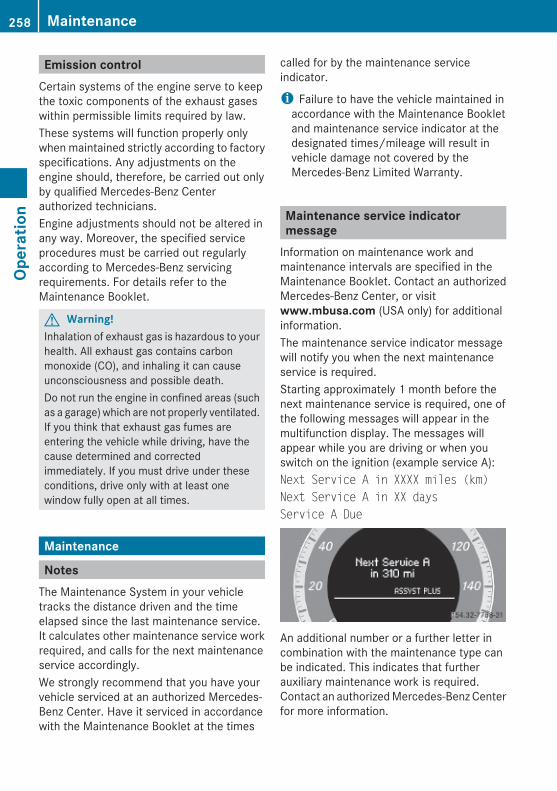
Emission controlCertain systems of the engine serve to keepthe toxic components of the exhaust gaseswithin permissible limits required by law.These systems will function properly onlywhen maintained strictly according to factoryspecifications. Any adjustments on theengine should, therefore, be carried out onlyby qualified Mercedes-Benz Centerauthorized technicians.Engine adjustments should not be altered inany way. Moreover, the specified serviceprocedures must be carried out regularlyaccording to Mercedes-Benz servicingrequirements. For details refer to theMaintenance Booklet.
G Warning!Inhalation of exhaust gas is hazardous to yourhealth. All exhaust gas contains carbonmonoxide (CO), and inhaling it can causeunconsciousness and possible death.Do not run the engine in confined areas (suchas a garage) which are not properly ventilated.If you think that exhaust gas fumes areentering the vehicle while driving, have thecause determined and correctedimmediately. If you must drive under theseconditions, drive only with at least onewindow fully open at all times.
Maintenance
NotesThe Maintenance System in your vehicletracks the distance driven and the timeelapsed since the last maintenance service.It calculates other maintenance service workrequired, and calls for the next maintenanceservice accordingly.We strongly recommend that you have yourvehicle serviced at an authorized Mercedes-Benz Center. Have it serviced in accordancewith the Maintenance Booklet at the times
called for by the maintenance serviceindicator.
i Failure to have the vehicle maintained inaccordance with the Maintenance Bookletand maintenance service indicator at thedesignated times/mileage will result invehicle damage not covered by theMercedes-Benz Limited Warranty.
Maintenance service indicator message
Information on maintenance work andmaintenance intervals are specified in theMaintenance Booklet. Contact an authorizedMercedes-Benz Center, or visitwww.mbusa.com (USA only) for additionalinformation.The maintenance service indicator messagewill notify you when the next maintenanceservice is required.Starting approximately 1 month before thenext maintenance service is required, one ofthe following messages will appear in themultifunction display. The messages willappear while you are driving or when youswitch on the ignition (example service A):Next Service A in XXXX miles (km)Next Service A in XX daysService A Due
An additional number or a further letter incombination with the maintenance type canbe indicated. This indicates that furtherauxiliary maintenance work is required.Contact an authorized Mercedes-Benz Centerfor more information.
258 MaintenanceOp
erat
ion
212_AKB; 2; 41, en-USd2ureepe, Version: 2.11.8.1
2009-07-17T09:14:21+02:00 - Seite 258
Clearing the maintenance service indicator messageThe maintenance service indicator messageis cleared automaticallyRafter approximately 10 seconds when you
switch on the ignitionRafter approximately 10 seconds when
reaching the service threshold while drivingRafter approximately 30 seconds, once the
suggested maintenance service term haspassed
X Clearing the maintenance service indicator message manually: Pressbutton % or button a on themultifunction steering wheel.The standard display appears in themultifunction display.
Maintenance service term exceeded If you have exceeded the suggestedmaintenance service term, you will see thefollowing message in the multifunctiondisplay:Service A Exceeded by XXXXX miles (km)Service A Exceeded by XXX daysIn addition, a signal sounds when themessage appears.Any authorized Mercedes-Benz Center willreset the maintenance service indicatorfollowing a completed maintenance service.
Calling up the maintenance service indicator display
i The menu overview can be found on(Y page 129).
You can call up the maintenance serviceindicator display at any time to check whenthe next maintenance service is required.
X Switch on the ignition.The standard display of the control systemappears (Y page 129).
X Press button = or ; on themultifunction steering wheel to select theServ. menu.
X Press button : or 9 to selectASSYST PLUS.
X Press button a on the multifunctionsteering wheel to confirm.The maintenance service indicator displaywith the maintenance service deadlineappears in the multifunction display.
i If the battery was disconnected, the daysof disconnection will not be included in thecount shown by the maintenance serviceindicator. To arrive at the true maintenanceservice deadline, you will need to subtractthese days from the days shown in themaintenance service indicator message ormaintenance service indicator display.
Resetting the maintenance service indicator
In the event that the maintenance service onyour vehicle is not carried out at an authorizedMercedes-Benz Center, you can have themaintenance service indicator reset.The automotive maintenance facility carryingout the maintenance service will find theinformation for resetting the maintenanceservice indicator in the maintenance-relevantliterature for your vehicle.Such literature is available at any authorizedMercedes-Benz Center or directly fromMercedes-Benz.
! If the maintenance service indicator wasreset inadvertently, have an authorizedMercedes-Benz Center correct it.Only reset the maintenance serviceindicator if the proper maintenance servicehas been performed. Not following theproper maintenance service as describedin the Maintenance Booklet will result in
Maintenance 259
Oper
atio
n
212_AKB; 2; 41, en-USd2ureepe, Version: 2.11.8.1
2009-07-17T09:14:21+02:00 - Seite 259
Z
engine damage and/or other vehicledamage not covered by the Mercedes-BenzLimited Warranty.
Vehicle care
Cleaning and care of the vehicle
NotesRegular and proper care will help to maintainthe value of your vehicle.
G Warning!Many cleaning products can be hazardous.Some are poisonous, others are flammable.Always follow the instructions on theparticular container. Always open yourvehicle’s doors or windows when cleaning theinside.Never use fluids or solvents that are notdesigned for cleaning your vehicle.Always lock away cleaning products and keepthem out of reach of children.
! When cleaning the vehicle, do not usescouring agents. Never apply strong forceand only use a soft, wet cloth or sponge.Otherwise you may scratch or damage thesurface to be cleaned.
While in operation, even while parked, yourvehicle is subjected to varying externalinfluences which, if gone unchecked, canattack the paintwork as well as the vehicleunderbody and cause lasting damage.Such damage is caused not only by extremeand varying climatic conditions, but also by:RAir pollutionRRoad saltRTarRGravel and stone chipping
To avoid paint damage, you shouldimmediately remove:RGrease and oilRFuelRCoolantRBrake fluidRBird droppingsRInsectsRTree resins etc.Frequent washing reduces and/or eliminatesthe aggressiveness and potency of the aboveadverse influences.More frequent washings are necessary todeal with unfavorable conditions:Rnear the oceanRin industrial areas (smoke, exhaust
emissions)Rduring winter operationYou should check your vehicle from time totime for stone chipping or other damage. Anydamage should be repaired as soon aspossible to prevent corrosion.In doing so, do not neglect the underbody ofthe vehicle. A prerequisite for a thoroughcheck is a washing of the underbody followedby a thorough inspection. Damaged areasneed to be re-undercoated.Your vehicle has been treated at the factorywith a wax-base rustproofing in the bodycavities which will last for the lifetime of thevehicle. Post-production treatment is neithernecessary nor recommended by Mercedes-Benz because of the possibility ofincompatibility between materials used in theproduction process and others applied later.We have selected vehicle-care products andcompiled recommendations which arespecially matched to our vehicles and whichalways reflect the latest technology. You canobtain Mercedes-Benz approved vehicle-careproducts at an authorized Mercedes-BenzCenter.
260 Vehicle careOp
erat
ion
212_AKB; 2; 41, en-USd2ureepe, Version: 2.11.8.1
2009-07-17T09:14:21+02:00 - Seite 260
Scratches, corrosive deposits, corrosion ordamage due to negligent or incorrect carecannot always be removed or repaired withthe vehicle-care products recommendedhere. In such cases it is best to seek aid at anauthorized Mercedes-Benz Center.The following topics deal with the cleaningand care of your vehicle and give important“how-to” information as well as references toMercedes-Benz approved vehicle-careproducts.
Power washer! Follow the instructions provided by the
power washer manufacturer onmaintaining a distance between the vehicleand the nozzle of the power washer.Never use a round nozzle to power-washtires. The intense jet of water can result indamage to the tire.Always replace a damaged tire.Always keep the jet of water moving acrossthe surface. Do not aim directly at electricalparts, electrical connectors, seals, or otherrubber parts.
i Vehicles with KEYLESS-GO:If a door handle is hit by a strong jet ofwater, and a SmartKey is withinapproximately 3 ft (1 m) of the vehicle, itcould be inadvertently locked or unlocked.
Tar stainsQuickly remove tar stains before they dry andbecome more difficult to remove. A tarremover is recommended.
Paintwork, painted body components! Affixing stickers, magnets, adhesive tape
or similar materials to painted bodycomponents may damage the paintwork.
Mercedes-Benz approved Paint Care shouldbe applied when water drops on the paintsurface do not “bead up”. This should
normally be done every 3 to 5 months,depending on the climate and washingdetergent used.Mercedes-Benz approved Paint Cleanershould be applied if the paint surface showssigns of embedded dirt (i.e. loss of gloss).Do not apply any of these products or wax ifyour vehicle is parked in the sun or if the hoodis still hot.X Use the appropriate MB-Touch-Up Stick for
quick and provisional repairs of minor paintdamage (i.e. chips from stones, vehicledoors, etc.).
Engine cleaningPrior to cleaning the engine compartment,make sure to protect electrical componentsand connectors from contact with water andcleaning agents.Corrosion protection, such as MBAnticorrosion Wax should be applied to theengine compartment after every enginecleaning. Before applying, all control linkagebushings and joints should be lubricated. Thepoly-V-belt and all pulleys should beprotected from any wax.
Vehicle washingIn the winter, thoroughly remove all traces ofroad salt as soon as possible.When washing the vehicle underbody, do notforget to clean the inner sides of the wheels.
i Vehicles with KEYLESS-GO:If a door handle is hit by a strong jet ofwater, and a SmartKey is withinapproximately 3 ft (1 m) of the vehicle, itcould be inadvertently locked or unlocked.
Hand-washX Do not use hot water or wash your vehicle
in direct sunlight.X Only use a soft, wet cloth or sponge to
clean the vehicle.
Vehicle care 261
Oper
atio
n
212_AKB; 2; 41, en-USd2ureepe, Version: 2.11.8.1
2009-07-17T09:14:21+02:00 - Seite 261
Z

X Only use a mild vehicle wash detergent,such as Mercedes-Benz approved CarShampoo.
X Thoroughly spray the vehicle with adiffused jet of water.
X Do not spray directly towards theventilation intake.
X Use plenty of water and rinse the spongeand chamois frequently.
X Rinse with clean water and dry with achamois thoroughly.Do not allow cleaning agents to dry on thefinish.
Automatic car washG Warning!The vehicle is braked when the HOLD functionor DISTRONIC PLUS is activated. Therefore,deactivate the HOLD function or DISTRONICPLUS before the vehicle is washed in anautomatic car wash.
You can have your vehicle washed in anautomatic car wash from the start. Brushlesscar washes are preferable.X To protect the filter system, activate the air
recirculation mode using button g onthe climate control panel.
! Do not clean your vehicle in an automatictouchless car wash which uses causticspray. Caustic spray will damage the paintor ornamental moldings.
If the vehicle is very dirty, prewash it beforerunning it through the automatic car wash.
! Make sure the combination switch is setto wiper setting $. Otherwise, the rainsensor could activate and cause the wipersto move unintentionally. This may lead tovehicle damage.Due to the width of the vehicle, fold inexterior rear view mirrors prior to runningthe vehicle through an automatic car washto prevent damage to the mirrors.
X When taking the vehicle through an automatic conveyor-type car wash:Make sure the automatic transmissionremains in neutral position N. Observeinstructions, see “Remaining in neutralposition N” (Y page 117).
When leaving the automatic car wash, makesure the mirrors are folded out.After running the vehicle through anautomatic car wash, wipe any wax off of thewindshield and the wiper blade inserts. Thiswill prevent smears and reduce wiping noisewhich can be caused by residual wax on thewindshield.
Ornamental moldingsX For regular cleaning and care of ornamental
moldings, use a damp cloth.
! Do not use chrome cleaner on ornamentalmoldings. Although ornamental moldingsmay have chrome appearance, they couldbe made of anodized aluminum that will bedamaged when cleaned with chromecleaner. Instead, use a damp cloth to cleanthose ornamental moldings.For very dirty ornamental moldings ofwhich you are sure are chrome-plated, usea chrome cleaner. If in doubt whether anornamental molding is chrome-plated,contact an authorized Mercedes-BenzCenter.
Headlamps, brake lamps, tail lamps, side markers, turn signal lensesX Use a mild vehicle wash detergent, such as
Mercedes-Benz approved Car Shampoo,with plenty of water.
! Only use window cleaning solutions thatare suitable for plastic lamp lenses.Window cleaning solutions which are notsuitable may damage the plastic lamplenses of the headlamps. Therefore, do notuse abrasives, solvents or cleaners thatcontain solvents.
262 Vehicle careOp
erat
ion
212_AKB; 2; 41, en-USd2ureepe, Version: 2.11.8.1
2009-07-17T09:14:21+02:00 - Seite 262

Cleaning the driving systems sensors
X Switch off the ignition.X Clean DISTRONIC PLUS/PRE-SAFE® Brake
system sensor cover : by hand.To clean DISTRONIC PLUS/PRE-SAFE® Brakesystem sensor cover : and the bumper areanear sensors ; observe the following:RUse a mild vehicle wash detergent, such as
Mercedes-Benz approved Car Shampoo,with plenty of water.RUse a soft, non-scratching cloth.
! If you use a power washer to clean thesensor covers, observe the following:RFollow the instructions provided by the
power washer manufacturer.RMaintain a distance between the sensor
covers and the nozzle of the powerwasher.
Cleaning the rear view camera lens
X Only use clean water and a soft, non-scratching cloth to clean rear view cameralens :.
Be careful not to apply wax to rear viewcamera lens : when waxing the vehicle. Ifnecessary, remove the wax using theMercedes-Benz approved Car Shampoo withplenty of water.
! Do not clean the camera and the areaaround the cameraRwith a high-pressure cleanerRwith a dry cloth and strong pressureRwith aggressive cleaning agentsYou could otherwise damage the camera.
Cleaning the windshield in front of the Night View Assist Plus cameraThe Night View Assist Plus camera is locatedin front of the interior rear view mirror.
G Warning!Please do not forget that your primaryresponsibility is to drive the vehicle. A driver’sattention to the road must always be his/herprimary focus when driving. For your safetyand the safety of others, stop before trying toremove window fogging or cleaning thewindow in front of the Night View Assist Pluscamera.Bear in mind that at a speed of just 30 mph(approximately 50 km/h), your vehicle is
Vehicle care 263
Oper
atio
n
212_AKB; 2; 41, en-USd2ureepe, Version: 2.11.8.1
2009-07-17T09:14:21+02:00 - Seite 263
Z

covering a distance of 44 feet (approximately14 m) every second.
! Do not clean the lens of the Night ViewAssist Plus camera. If the camera lens isdirty, please contact an authorizedMercedes-Benz Center.
X Use recessed handle : of camera cover toswing camera cover downward.
X Clean inside of windshield in front ofcamera ; with a soft, non-scratchingcloth.
! If you use a windshield cleaning product,make sure that none of the cleaningproduct comes into contact with the lensof the Night View Assist Plus camera.
X Use recessed handle : of camera cover toswing camera cover up.
Cleaning the windows and the wiper blades! Never open the hood when the wiper arms
are folded forward.
G Warning!For safety reasons, switch off wipers andremove SmartKey from starter switch beforecleaning the windshield and/or the wiperblades. Vehicles with KEYLESS-GO: Makesure the vehicle’s on-board electronics havestatus 0. Otherwise, the wiper motor couldsuddenly turn on and cause injury.
! Do not pull on the wiper blade inserts.They could tear.
X Fold the wiper arms forward until they snapinto place.
X Clean the windshield and the wiper bladeinserts with a clean cloth and milddetergent solution.
X Use a soft, clean cloth and a mild windowcleaning solution on all outside and insideglass surfaces.An automotive glass cleaner isrecommended.
! Fold the windshield wiper arms back ontothe windshield before turning the SmartKeyin the starter switch or pressing theKEYLESS-GO start/stop button.Hold on to the wiper when folding the wiperarm back. If released, the force of theimpact from the tensioning spring couldcrack the windshield.
! To clean the window interior, do not usea dry cloth, abrasives, solvents or cleanerscontaining solvents. Do not touch theinside of the windows with hard objectssuch as an ice scraper or ring. Doing so maydamage the windows.
264 Vehicle careOp
erat
ion
212_AKB; 2; 41, en-USd2ureepe, Version: 2.11.8.1
2009-07-17T09:14:21+02:00 - Seite 264

Cleaning the panorama roofThe rear part of the tilt/sliding panel has aprotective layer on the inside.X Use a soft, clean cloth and a mild window
cleaning solution.An automotive glass cleaner isrecommended.
! Do not use a dry cloth, abrasives, solventsor cleaners containing solvents. Do nottouch the protective layer with hard objectssuch as an ice scraper or ring. Never applystrong force and only use a soft, non-scratching cloth when cleaning the rearpart of the tilt/sliding panel.Otherwise you may scratch or damage theprotective layer.
Light alloy wheelsIf possible, clean wheels once a week.X Use Mercedes-Benz approved Wheel Care,
a soft bristle brush and a strong spray ofwater for cleaning the light alloy wheels.
! Only use acid-free cleaning materials.Acid may cause corrosion or damage theclear coat.
! The vehicle should not be parked for anextended period of time immediately afterit has been cleaned. This applies especiallyafter the wheel rims have been cleanedwith wheel rim cleaner. Wheel rim cleanerscan lead to increased corrosion of thebrake disks and brake pads. Non-approvedwheel cleaners may also damage the wheelpaint if the vehicle is not driven aftercleaning.Therefore, the vehicle’s brake systemshould always be warmed-up before it isparked after cleaning. Drive your vehicle forseveral minutes to allow the brakes to dry.When applying Mercedes-Benz approvedTire Care and Mercedes-Benz approvedWheel Care products, take care not tospray them on the brake disks.
Plastic and rubber partsX Use a gentle dishwashing detergent or mild
detergent for delicate fabrics as a washingsolution.
X Wipe with a cloth moistened in a lukewarmsolution.The surface may temporarily change color.If this is the case, wait for it to dry.
G Warning!Do not use cleaners or cockpit care sprayscontaining solvents to clean the cockpit or thesteering wheel. Cleaners containing solventswill make the surface porous and vehicleoccupants could suffer serious injuries fromplastic parts coming loose in the event of airbag deployment.
! Do not use oil, wax or scouring agents.Otherwise you may scratch or damage thesurface.
Hard plastic trim items X Use Mercedes-Benz approved Interior Care
on a soft, lint-free cloth and apply with lightpressure.
COMAND display! You must switch off the COMAND display
and allow it to cool prior to cleaning.
! Do not use any liquids or cleaning agents.These can damage or even destroy theCOMAND display screen.
X Use a standard microfiber cloth and applywith light pressure.
Steering wheel and gear selector leverX Wipe with a damp cloth and dry thoroughly
or clean with Mercedes-Benz approvedLeather Care.
Vehicle care 265
Oper
atio
n
212_AKB; 2; 41, en-USd2ureepe, Version: 2.11.8.1
2009-07-17T09:14:21+02:00 - Seite 265
Z
CarpetsX Use Mercedes-Benz approved Carpet and
Fabric Care for cleaning the carpets.
Headliner and shelf below rear windowX Use a soft bristle brush or a dry-shampoo
cleaner in case of excessive dirt.
Seat beltsX Only use clear, lukewarm water and soap.
! The seat belts must not be treated withchemical cleaning agents. Do not dry theseat belts at temperatures above 176‡(80†) or in direct sunlight.
G Warning!Do not bleach or dye seat belts as this mayseverely weaken them. In a crash they maynot be able to provide adequate protection.
UpholsteryUsing aftermarket seat covers or wearingclothing that have the tendency to give offcoloring (e.g. when wet, etc.) may cause theupholstery to become permanentlydiscolored. By lining the seats with a properintermediate cover, contact-discoloration willbe prevented.
G Warning!Only use seat or head restraint covers whichhave been tested and approved by Mercedes-Benz for your vehicle model.Using other seat or head restraint covers mayinterfere with or preventRdeployment of the front side impact air
bagsRdeployment of the rear side impact air bagsRdeployment of the pelvis air bagsRactivation of the NECK-PRO active front
head restraints
Contact an authorized Mercedes-Benz Centerfor availability.
Leather upholsteryPlease note that leather upholstery is anatural product and is therefore subject to anatural aging process. Leather upholsterymay also react to certain ambient influencessuch as high humidity or high temperature byshowing wrinkles for example.X Wipe leather upholstery with a damp cloth
and dry thoroughly or clean with Mercedes-Benz approved Leather Care.
! To avoid damage to leather upholstery:RWipe with light pressure only.RDo not clean with abrasive cleaning
agents such as scouring milk or powder.RDo not soak the leather upholstery.
As leather is a natural product, it couldotherwise harden or become porous.RExercise particular care when cleaning
perforated leather as its undersideshould not become wet.
Wood trimsX Only use water and a damp cloth to clean
wood trims in your vehicle.
! Do not use solvents like tar remover orwheel cleaner nor polishes or waxes asthese may be abrasive.
Chrome-plated exhaust tipRegular cleaning and care of chrome-platedexhaust tips will help to maintain their shineand the classy appearance.X Use Mercedes-Benz approved Chrome
Polishing Paste each time the vehicle hasbeen washed, especially during the winter.
! Do not use alkaline cleaners such aswheel cleaners as they could causecorrosion.
266 Vehicle careOp
erat
ion
212_AKB; 2; 41, en-USd2ureepe, Version: 2.11.8.1
2009-07-17T09:14:21+02:00 - Seite 266

Vehicle equipment ............................ 268Where will I find ...? .......................... 268Vehicle status messages in themultifunction display ....................... 272What to do if … .................................. 304Unlocking/locking manually ........... 314Resetting activated NECK-PROactive front head restraints ............. 316Replacing SmartKey batteries ......... 317Replacing bulbs ................................. 318Replacing wiper blades .................... 322Flat tire .............................................. 323Bleeding the fuel system (dieselengine only) ....................................... 333AdBlue® (diesel engine only) ........... 333Battery ............................................... 336Jump starting .................................... 338Towing the vehicle ............................ 340Fuses .................................................. 343
267
Prac
tical
hin
ts
212_AKB; 2; 41, en-USd2ureepe, Version: 2.11.8.1
2009-07-17T09:14:21+02:00 - Seite 267

Vehicle equipment
i This Operator’s Manual describes allfeatures, standard or optional, potentiallyavailable for your vehicle at the time ofpurchase. Please be aware that yourvehicle might not be equipped with allfeatures described in this manual.
Where will I find ...?
First aid kiti Check expiration dates and contents for
completeness at least once a year andreplace missing/expired items.
The first-aid kit is located in the trunk on theright-hand side behind the cover.
X Turn the lock clockwise and fold down thecover.
X Loosen tensioning strap :.First aid kit ; can be removed.
Vehicle tool kitThe vehicle tool kit is located in the spaceunderneath the trunk floor.
i Vehicles without spare wheel are notfactory-equipped with the tools required fora wheel change such as a jack or a wheel
wrench. Some tools required for a wheelchange are specific to your vehicle.Contact an authorized Mercedes-BenzCenter to obtain the tools approved foryour vehicle.
The vehicle tool kit includes:RCollapsible wheel chock16
RElectric air pump17,18
RFuse chartRJack16
RPair of gloves16
RProtective wrap17
RTIREFIT kit18
RTowing eye boltRWheel wrench16
X Open the trunk (Y page 81).
X Lift the trunk floor using floor handle :.
16 Vehicles with spare wheel only.17 E 63 AMG18 E 350 BlueTEC (if so equipped)
268 Where will I find ...?Pr
actic
al h
ints
212_AKB; 2; 41, en-USd2ureepe, Version: 2.11.8.1
2009-07-17T09:14:21+02:00 - Seite 268

X Engage floor handle = on upper trunklip ;.
Vehicles without spare wheeli Vehicles without spare wheel are not
factory-equipped with the tools required fora wheel change such as a jack or a wheelwrench. Some tools required for a wheelchange are specific to your vehicle.Contact an authorized Mercedes-BenzCenter to obtain the tools approved foryour vehicle. The illustration shows thevehicle retrofitted with the necessary toolsfor a wheel change.
i USA only: Vehicles with MOExtendedsystem are not factory-equipped with aTIREFIT kit. When retrofitting with tires thatdo not have run-flat characteristics, youshould also equip your vehicle with aTIREFIT kit. TIREFIT kits are available at anyauthorized Mercedes-Benz Center.
E 350 BlueTEC: TIREFIT kit; Electric air pump= Jack? Towing eye boltA Wheel wrenchB Fuse chartC Collapsible wheel chockD Alignment bolt
Vehicles with spare wheel
All models except E 63 AMG
: Tab; Removing vehicle tool kit box= Vehicle tool kit box coverA Opening vehicle tool kit box coverB TabC Vehicle tool kitD Vehicle tool kit boxE Luggage bowl
Where will I find ...? 269
Prac
tical
hin
ts
212_AKB; 2; 41, en-USd2ureepe, Version: 2.11.8.1
2009-07-17T09:14:21+02:00 - Seite 269
Z
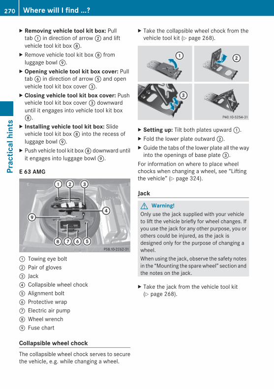
X Removing vehicle tool kit box: Pulltab : in direction of arrow ; and liftvehicle tool kit box D.
X Remove vehicle tool kit box D fromluggage bowl E.
X Opening vehicle tool kit box cover: Pulltab B in direction of arrow A and openvehicle tool kit box cover =.
X Closing vehicle tool kit box cover: Pushvehicle tool kit box cover = downwarduntil it engages into vehicle tool kit boxD.
X Installing vehicle tool kit box: Slidevehicle tool kit box D into the recess ofluggage bowl E.
X Push vehicle tool kit box D downward untilit engages into luggage bowl E.
E 63 AMG
: Towing eye bolt; Pair of gloves= Jack? Collapsible wheel chockA Alignment boltB Protective wrapC Electric air pumpD Wheel wrenchE Fuse chart
Collapsible wheel chock The collapsible wheel chock serves to securethe vehicle, e.g. while changing a wheel.
X Take the collapsible wheel chock from thevehicle tool kit (Y page 268).
X Setting up: Tilt both plates upward :.X Fold the lower plate outward ;.X Guide the tabs of the lower plate all the way
into the openings of base plate =.For information on where to place wheelchocks when changing a wheel, see “Liftingthe vehicle” (Y page 324).
Jack
G Warning!Only use the jack supplied with your vehicleto lift the vehicle briefly for wheel changes. Ifyou use the jack for any other purpose, you orothers could be injured, as the jack isdesigned only for the purpose of changing awheel.When using the jack, observe the safety notesin the “Mounting the spare wheel” section andthe notes on the jack.
X Take the jack from the vehicle tool kit(Y page 268).
270 Where will I find ...?Pr
actic
al h
ints
212_AKB; 2; 41, en-USd2ureepe, Version: 2.11.8.1
2009-07-17T09:14:21+02:00 - Seite 270

Storage position
X Turn the crank handle in the direction ofarrow as far as it will go.
Operational position
X Turn the crank handle clockwise.
Before placing the jack back into the vehicletool kit:X Fully collapse the jack.X Fold in the crank handle (storage position).
Spare wheel
G Observe Safety notes, see page 323.
i The E 350 BlueTEC does not have a sparewheel.
The spare wheel is located in the spaceunderneath the trunk floor.X Removing: Open the trunk (Y page 81).X Lift the trunk floor and secure it on the
upper trunk lip (Y page 268).
! To prevent damage, always disengage thefloor handle from the upper trunk lip andlower the trunk floor before closing thetrunk.
All models except E 63 AMG
X Removing: Remove luggage bowl ; byturning it counterclockwise.
X Remove spare wheel :.
Storing the spare wheel after useX Place spare wheel : into the spare wheel
well.X Secure spare wheel : by turning luggage
bowl ; clockwise.
E 63 AMG
X Removing: Reach into recess : ofstorage well casing to pull it up and removeit.
X Remove spare wheel ;.
Where will I find ...? 271
Prac
tical
hin
ts
212_AKB; 2; 41, en-USd2ureepe, Version: 2.11.8.1
2009-07-17T09:14:21+02:00 - Seite 271
Z
Storing the spare wheel after useIf you wish to store the spare wheel after use,carry out the following steps. Otherwise, thespare wheel may not fit into the spare wheelwell.
! Make sure the spare wheel is dry beforestoring it.
X Unscrew the valve cap from the valve of thecollapsible tire.
X Unscrew the valve insert from the valveusing the valve extractor integrated in thevalve cap.
X Allow the air to escape.
i It may take a few minutes for thecollapsible tire to deflate completely.
X Screw the valve insert back into the valve.X Screw the valve cap back onto the valve.X Take the protective wrap from the vehicle
tool kit (Y page 268).X Pull the protective wrap over the spare
wheel.X Place the spare wheel into the spare wheel
well.
Vehicle status messages in the multifunction display
NotesWarning and malfunction messages appear inthe multifunction display located in theinstrument cluster.Certain warning and malfunction messagesare accompanied by an audible signal.Address these messages accordingly andfollow the additional instructions given in thisOperator’s Manual.High-priority messages appear in themultifunction display in red color.Certain messages of high priority cannot becleared from the multifunction display usinga or % on the multifunction steeringwheel (Y page 126).
Other messages of high priority andmessages of less immediate priority can becleared from the multifunction display usinga or %. They are then stored in thevehicle status message memory(Y page 139). Remember that clearing amessage will only make the messagedisappear. Clearing a message will notcorrect the condition that caused themessage to appear.
G Warning!All categories of messages contain importantinformation which should be taken note ofand, where a malfunction is indicated,addressed as soon as possible at anauthorized Mercedes-Benz Center.Failure to repair the condition noted maycause damage not covered by the Mercedes-Benz Limited Warranty, or result in propertydamage or personal injury.
G Warning!No messages will be displayed if either theinstrument cluster or the multifunctiondisplay is inoperative.As a result, you will not be able to seeinformation about your driving conditions,such asRspeedRoutside temperatureRwarning/indicator lampsRmalfunction/warning messagesRfailure of any systems
Driving characteristics may be impaired.If you must continue to drive, do so with addedcaution. Contact an authorized Mercedes-Benz Center as soon as possible.
Read and observe the notes on the HOLDfunction (Y page 161) and parking(Y page 113) when you park the vehicle.On the pages that follow, you will find acompilation of the most important warningand malfunction messages that may appear.
272 Vehicle status messages in the multifunction displayPr
actic
al h
ints
212_AKB; 2; 41, en-USd2ureepe, Version: 2.11.8.1
2009-07-17T09:14:21+02:00 - Seite 272

For your convenience the messages aredivided into text messages (Y page 274) andsymbol messages (Y page 287).
Vehicle status messages in the multifunction display 273
Prac
tical
hin
ts
212_AKB; 2; 41, en-USd2ureepe, Version: 2.11.8.1
2009-07-17T09:14:21+02:00 - Seite 273
Z

Text messages
Safety systems
Display messages Possible causes/consequences and M Solutions
PRE-SAFE Inoperative See Operator's Manual
The PRE-SAFE® system has failed. All other occupant safetysystems, such as the air bags, are still available.X Contact an authorized Mercedes-Benz Center as soon as
possible.
PRE-SAFE Functions Currently Limited See Operator's Manual
The PRE-SAFE® Brake is temporarily unavailable.The PRE-SAFE® Brake is deactivated because:Rthe DISTRONIC PLUS cover in the radiator grille is dirtyRthe area around the sensors in the front or the rear bumper
is dirtyRits function is impaired as a result of heavy precipitationRthe radar sensor system is temporarily inoperative due to
electromagnetic interference near television and radiotransmitter stations, toll stations, speed measuringsystems, etc.Rthe system is out of the operating temperature rangeRthe battery voltage is insufficientRE 63 AMG only: The ESC has been switched off.
The PRE-SAFE® Brake becomes operational again and themessage in the multifunction display disappears when:Rdirt on the radiator grille has fallen off while driving (e.g.
slush or snow)Rthe system recognizes full sensor availability (due to
lessening rain or the road surface drying)Rthe system is within the operating temperature rangeRE 63 AMG only: The ESC is switched back on.If the message in the multifunction display does notdisappear:X Clean the DISTRONIC PLUS cover in the radiator grille
(Y page 263).X Clean the front and the rear bumper (Y page 263).X Restart the vehicle.X Wait until the battery recovers.
274 Vehicle status messages in the multifunction displayPr
actic
al h
ints
212_AKB; 2; 41, en-USd2ureepe, Version: 2.11.8.1
2009-07-17T09:14:21+02:00 - Seite 274
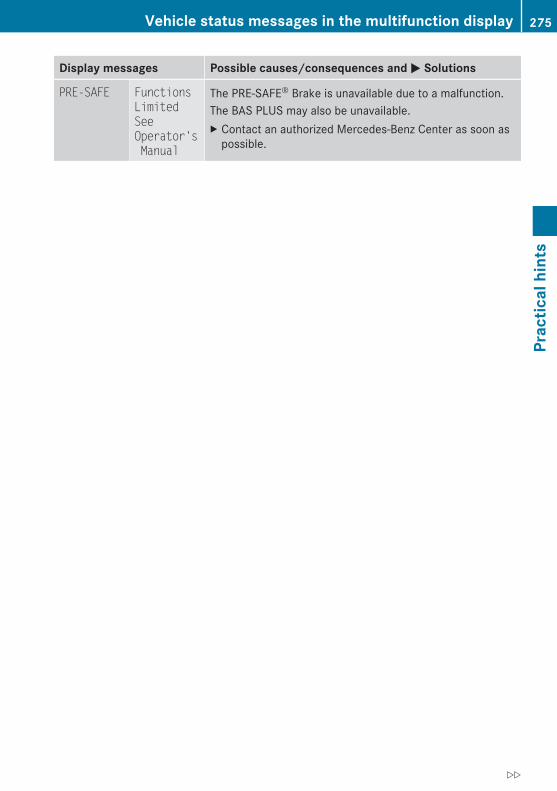
Display messages Possible causes/consequences and M Solutions
PRE-SAFE Functions Limited See Operator's Manual
The PRE-SAFE® Brake is unavailable due to a malfunction.The BAS PLUS may also be unavailable.X Contact an authorized Mercedes-Benz Center as soon as
possible.
Vehicle status messages in the multifunction display 275
Prac
tical
hin
ts
212_AKB; 2; 41, en-USd2ureepe, Version: 2.11.8.1
2009-07-17T09:14:21+02:00 - Seite 275
Z

Display messages Possible causes/consequences and M Solutions
Front Passenger Airbag Enabled See Operator’s Manual
USA only:The front passenger front air bag is activated while drivingeven though a child, small individual, or object below thesystem’s weight threshold is on the front passenger seat, orthe front passenger seat is empty. Objects on the seat orforces acting on the seat may make the system sensesupplemental weight.X Stop the vehicle in a safe location as soon as possible.X Engage the parking brake.X Switch off the ignition.X Open the front passenger door.X Remove child and child restraint from front passenger seat
and properly secure the child in rear seat employing thechild restraint if necessary.
X Make sure no objects which apply supplemental weight tothe seat are present. The system may recognize suchsupplemental weight and sense that an occupant on thefront passenger seat is of a greater weight than actuallypresent.
X Keep the seat unoccupied, close the front passenger doorand switch on the ignition.
Monitor the 45 indicator lamp in the center console(Y page 45) and the multifunction display in the instrumentcluster (Y page 28) for the following:With the seat unoccupied and the ignition switched on,Rthe 45 indicator lamp in the center console should
illuminate and remain illuminated, indicating that the OCS(Y page 43) has deactivated the front passenger front airbag.Rthe message Front Passenger Airbag Enabled See Operator’s Manual or the message Front Passenger Airbag Disabled See Operator’s Manual should notappear in the multifunction display at any time the seat isunoccupied. Wait at least 60 seconds for the system tocomplete the necessary check cycles and to make sureneither message appears in the multifunction display.
If above conditions are met, you can occupy the frontpassenger seat again. Depending on the front passengerclassification sensed by the OCS, the 45 indicatorlamp will remain illuminated or go out.
276 Vehicle status messages in the multifunction displayPr
actic
al h
ints
212_AKB; 2; 41, en-USd2ureepe, Version: 2.11.8.1
2009-07-17T09:14:21+02:00 - Seite 276

Display messages Possible causes/consequences and M SolutionsIf above conditions are not met, the system is not workingproperly. Have the system checked at an authorizedMercedes-Benz Center as soon as possible.
G Warning!If the 45 indicator lamp remains out even after performing the above corrective steps,do not have any children 12 years old and under and other small individuals use the passengerseat until the system has been repaired.
Vehicle status messages in the multifunction display 277
Prac
tical
hin
ts
212_AKB; 2; 41, en-USd2ureepe, Version: 2.11.8.1
2009-07-17T09:14:21+02:00 - Seite 277
Z
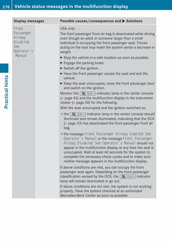
Display messages Possible causes/consequences and M Solutions
Front Passenger Airbag Disabled See Operator’s Manual
USA only:The front passenger front air bag is deactivated while drivingeven though an adult or someone larger than a smallindividual is occupying the front passenger seat. Forcesacting on the seat may make the system sense a decrease inweight.X Stop the vehicle in a safe location as soon as possible.X Engage the parking brake.X Switch off the ignition.X Have the front passenger vacate the seat and exit the
vehicle.X Keep the seat unoccupied, close the front passenger door
and switch on the ignition.Monitor the 45 indicator lamp in the center console(Y page 45) and the multifunction display in the instrumentcluster (Y page 28) for the following:With the seat unoccupied and the ignition switched on,Rthe 45 indicator lamp in the center console should
illuminate and remain illuminated, indicating that the OCS(Y page 43) has deactivated the front passenger front airbag.Rthe message Front Passenger Airbag Enabled See Operator’s Manual or the message Front Passenger Airbag Disabled See Operator’s Manual should notappear in the multifunction display at any time the seat isunoccupied. Wait at least 60 seconds for the system tocomplete the necessary check cycles and to make sureneither message appears in the multifunction display.
If above conditions are met, you can occupy the frontpassenger seat again. Depending on the front passengerclassification sensed by the OCS, the 45 indicatorlamp will remain illuminated or go out.If above conditions are not met, the system is not workingproperly. Have the system checked at an authorizedMercedes-Benz Center as soon as possible.
278 Vehicle status messages in the multifunction displayPr
actic
al h
ints
212_AKB; 2; 41, en-USd2ureepe, Version: 2.11.8.1
2009-07-17T09:14:21+02:00 - Seite 278
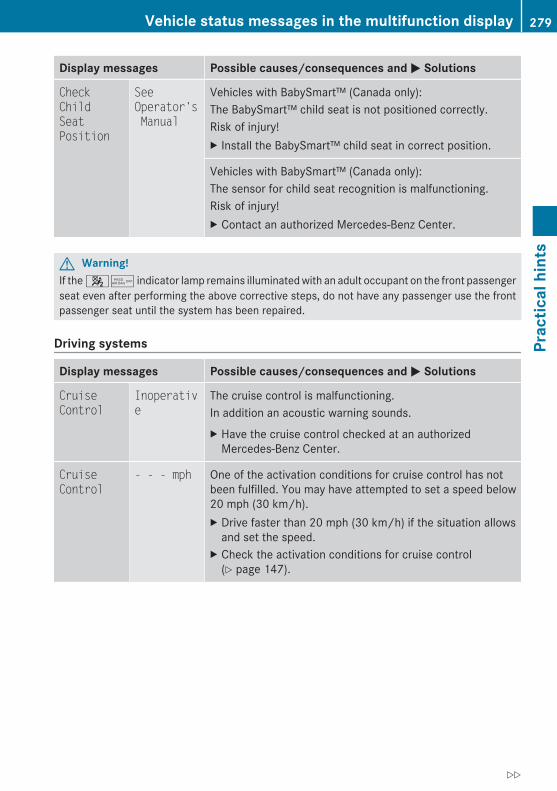
Display messages Possible causes/consequences and M Solutions
Check Child Seat Position
See Operator's Manual
Vehicles with BabySmart™ (Canada only):The BabySmart™ child seat is not positioned correctly.Risk of injury!X Install the BabySmart™ child seat in correct position.
Vehicles with BabySmart™ (Canada only):The sensor for child seat recognition is malfunctioning.Risk of injury!X Contact an authorized Mercedes-Benz Center.
G Warning!If the 45 indicator lamp remains illuminated with an adult occupant on the front passengerseat even after performing the above corrective steps, do not have any passenger use the frontpassenger seat until the system has been repaired.
Driving systems
Display messages Possible causes/consequences and M Solutions
Cruise Control
Inoperative
The cruise control is malfunctioning.In addition an acoustic warning sounds.X Have the cruise control checked at an authorized
Mercedes-Benz Center.
Cruise Control
- - - mph One of the activation conditions for cruise control has notbeen fulfilled. You may have attempted to set a speed below20 mph (30 km/h).X Drive faster than 20 mph (30 km/h) if the situation allows
and set the speed.X Check the activation conditions for cruise control
(Y page 147).
Vehicle status messages in the multifunction display 279
Prac
tical
hin
ts
212_AKB; 2; 41, en-USd2ureepe, Version: 2.11.8.1
2009-07-17T09:14:21+02:00 - Seite 279
Z

Display messages Possible causes/consequences and M Solutions
DISTRONIC PLUS
Currently Unavailable See Operator's Manual
The DISTRONIC PLUS is temporarily unavailable.The DISTRONIC PLUS is deactivated because:Rthe DISTRONIC PLUS cover in the radiator grille is dirtyRits function is impaired as a result of heavy precipitationRthe radar sensor system is temporarily inoperative due to
electromagnetic interference near television and radiotransmitter stations, toll stations, speed measuringsystems, etc.Rthe radar sensors do not sense any other vehicles or
objects, i.e. road sign or similar to this, for a long timeRthe system is out of the operating temperature rangeRthe battery voltage is insufficientX If necessary, clean the DISTRONIC PLUS cover in the
radiator grille (Y page 263).X Restart the vehicle.X Try activating the DISTRONIC PLUS again later.X Wait until the system is within the operating temperature
range or the battery recovers.The DISTRONIC PLUS becomes operational again without theengine being restarted when:Rdirt on the radiator grille has fallen off while driving (e.g.
slush or snow)Rthe system recognizes full sensor availability (due to
lessening rain or the road surface drying)Rthe message in the multifunction display disappears
DISTRONIC PLUS
Inoperative
The DISTRONIC PLUS is malfunctioning.The BAS PLUS and the PRE-SAFE® Brake are also notavailable.X Contact an authorized Mercedes-Benz Center as soon as
possible.
DISTRONIC PLUS
Override You have accelerated. The DISTRONIC PLUS has switched off.X Stop accelerating.
280 Vehicle status messages in the multifunction displayPr
actic
al h
ints
212_AKB; 2; 41, en-USd2ureepe, Version: 2.11.8.1
2009-07-17T09:14:21+02:00 - Seite 280

Display messages Possible causes/consequences and M Solutions
DISTRONIC PLUS
- - - mph One of the activation conditions for the DISTRONIC PLUS hasnot been fulfilled. You may have attempted to set a speedbelow 20 mph (30 km/h).X Drive faster than 20 mph (30 km/h) if the situation allows
and set the speed.X Check the activation conditions for the DISTRONIC PLUS
(Y page 153).
HOLD Off The HOLD function switched off because the vehicle wassliding, for example on a slippery surface.X Activate the HOLD function later.
Blind Spot Assist
Currently Unavailable See Operator's Manual
The Blind Spot Assist is deactivated because the area aroundthe sensors in the front or the rear bumper is dirty.X Clean the front and rear bumper (Y page 263).
The Blind Spot Assist is deactivated because the batteryvoltage is insufficient.X Have the battery checked at an authorized Mercedes-Benz
Center.
The Blind Spot Assist is switched off because the radar sensorsystem is temporarily inoperative due to electromagneticinterference near television and radio transmitter stations,toll stations, speed measuring systems, etc.X Wait until the message in the multifunction display
disappears.
Blind Spot Assist
Inoperative
The Blind Spot Assist is malfunctioning.X Contact an authorized Mercedes-Benz Center as soon as
possible.
Parking Guidance
Inoperative
The Parktronic system is malfunctioning.X Have the system checked at an authorized Mercedes-Benz
Center as soon as possible.
Vehicle status messages in the multifunction display 281
Prac
tical
hin
ts
212_AKB; 2; 41, en-USd2ureepe, Version: 2.11.8.1
2009-07-17T09:14:21+02:00 - Seite 281
Z
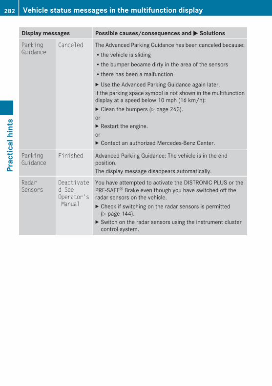
Display messages Possible causes/consequences and M Solutions
Parking Guidance
Canceled The Advanced Parking Guidance has been canceled because:Rthe vehicle is slidingRthe bumper became dirty in the area of the sensorsRthere has been a malfunctionX Use the Advanced Parking Guidance again later.If the parking space symbol is not shown in the multifunctiondisplay at a speed below 10 mph (16 km/h):X Clean the bumpers (Y page 263).orX Restart the engine.orX Contact an authorized Mercedes-Benz Center.
Parking Guidance
Finished Advanced Parking Guidance: The vehicle is in the endposition.The display message disappears automatically.
Radar Sensors
Deactivated See Operator's Manual
You have attempted to activate the DISTRONIC PLUS or thePRE-SAFE® Brake even though you have switched off theradar sensors on the vehicle.X Check if switching on the radar sensors is permitted
(Y page 144).X Switch on the radar sensors using the instrument cluster
control system.
282 Vehicle status messages in the multifunction displayPr
actic
al h
ints
212_AKB; 2; 41, en-USd2ureepe, Version: 2.11.8.1
2009-07-17T09:14:21+02:00 - Seite 282

Display messages Possible causes/consequences and M Solutions
Lane Keeping Assist
Currently Unavailable See Operator's Manual
The Lane Keeping Assist is temporarily unavailable.The Lane Keeping Assist is deactivated because:Rthe windshield in front of the camera is dirtyRits function is impaired as a result of heavy precipitation or
fogRlane markings are not present for an extended period of
timeRlane markings are worn, dark, or covered by dirt or snow
for exampleThe Lane Keeping Assist becomes operational again and themessage in the multifunction display disappears when:Rdirt on the windshield has fallen off while driving (e.g. slush
or snow)Rthe system recognizes full camera availabilityX If necessary, clean the windshield in front of the camera
(Y page 264).
Lane Keeping Assist
Inoperative
The Lane Keeping Assist is malfunctioning.X Contact an authorized Mercedes-Benz Center.
Vehicle
Display messages Possible causes/consequences and M Solutions
Apply Brake
to Shift from 'P'
You have attempted to shift the automatic transmission intodrive position D, reverse gear R or neutral position N withoutdepressing the brake pedal.X Depress the brake pedal.
Door Open Vehicle Not in 'P'
In addition an acoustic warning sounds.You have opened the driver’s door and the automatictransmission is still in drive position D, reverse gear R orneutral position N.X Before you leave the vehicle, make sure the automatic
transmission is in park position P and the parking brake isengaged.
Vehicle status messages in the multifunction display 283
Prac
tical
hin
ts
212_AKB; 2; 41, en-USd2ureepe, Version: 2.11.8.1
2009-07-17T09:14:21+02:00 - Seite 283
Z
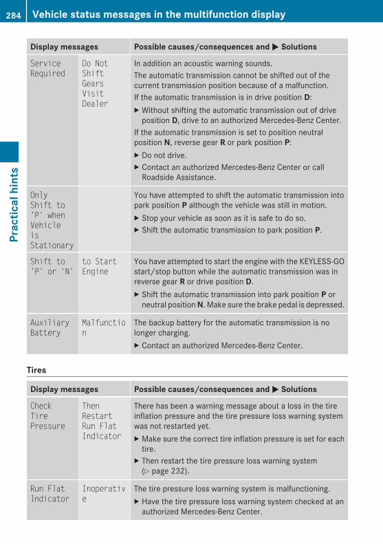
Display messages Possible causes/consequences and M Solutions
Service Required
Do Not Shift Gears Visit Dealer
In addition an acoustic warning sounds.The automatic transmission cannot be shifted out of thecurrent transmission position because of a malfunction.If the automatic transmission is in drive position D:X Without shifting the automatic transmission out of drive
position D, drive to an authorized Mercedes-Benz Center.If the automatic transmission is set to position neutralposition N, reverse gear R or park position P:X Do not drive.X Contact an authorized Mercedes-Benz Center or call
Roadside Assistance.
Only Shift to 'P' when Vehicle is Stationary
You have attempted to shift the automatic transmission intopark position P although the vehicle was still in motion.X Stop your vehicle as soon as it is safe to do so.X Shift the automatic transmission to park position P.
Shift to 'P' or 'N'
to Start Engine
You have attempted to start the engine with the KEYLESS-GOstart/stop button while the automatic transmission was inreverse gear R or drive position D.X Shift the automatic transmission into park position P or
neutral position N. Make sure the brake pedal is depressed.
Auxiliary Battery
Malfunction
The backup battery for the automatic transmission is nolonger charging.X Contact an authorized Mercedes-Benz Center.
Tires
Display messages Possible causes/consequences and M Solutions
Check Tire Pressure
Then Restart Run Flat Indicator
There has been a warning message about a loss in the tireinflation pressure and the tire pressure loss warning systemwas not restarted yet.X Make sure the correct tire inflation pressure is set for each
tire.X Then restart the tire pressure loss warning system
(Y page 232).
Run Flat Indicator
Inoperative
The tire pressure loss warning system is malfunctioning.X Have the tire pressure loss warning system checked at an
authorized Mercedes-Benz Center.
284 Vehicle status messages in the multifunction displayPr
actic
al h
ints
212_AKB; 2; 41, en-USd2ureepe, Version: 2.11.8.1
2009-07-17T09:14:21+02:00 - Seite 284

Display messages Possible causes/consequences and M Solutions
Check Tire Pressure Soon
The tire pressure loss warning system indicates that the tireinflation pressure is too low in at least one tire.X Carefully bring the vehicle to a halt, avoiding abrupt
steering and braking maneuvers. Observe the trafficsituation around you.
X Check the tires and, if necessary, change the wheel(Y page 323).
X Check and adjust tire inflation pressure as required(Y page 231).
X Restart the tire pressure loss warning system afteradjusting the tire inflation pressure values (Y page 232).
Tire pressures will be displayed
after driving a few minutes
The tire inflation pressure is being checked by the AdvancedTPMS.X Drive the vehicle for a few minutes.
Tire Press. Monitor
Inoperative
The Advanced TPMS is malfunctioning.X Have the Advanced TPMS checked at an authorized
Mercedes-Benz Center.
Tire Pressure Monitor
Inoperative No Wheel Sensors
There are wheels without appropriate wheel sensors mounted(e.g. winter tires).X Have the Advanced TPMS checked at an authorized
Mercedes-Benz Center.X Have the appropriate wheel sensors installed at an
authorized Mercedes-Benz Center.
TirePress. Sensor(s)Missing
At least one sensor is defect (e.g. battery is empty).The respective tire is indicated by – – instead of the tireinflation pressure in the multifunction display.X Have the Advanced TPMS checked at an authorized
Mercedes-Benz Center.X Have the wheel sensors installed at an authorized
Mercedes-Benz Center.
At least one wheel without appropriate wheel sensors ismounted (e.g. spare wheel).The respective tire is indicated by – – instead of the tireinflation pressure in the multifunction display.X Have the Advanced TPMS checked at an authorized
Mercedes-Benz Center.X Have the wheel sensors installed at an authorized
Mercedes-Benz Center.
Vehicle status messages in the multifunction display 285
Prac
tical
hin
ts
212_AKB; 2; 41, en-USd2ureepe, Version: 2.11.8.1
2009-07-17T09:14:21+02:00 - Seite 285
Z
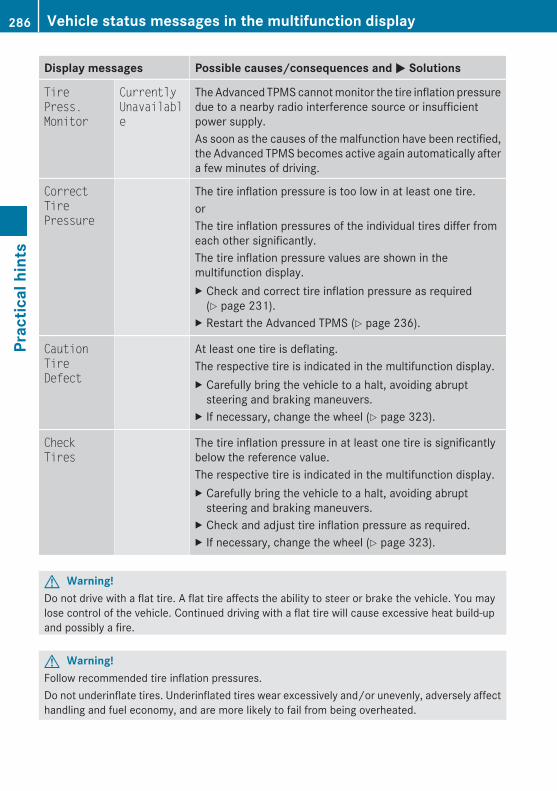
Display messages Possible causes/consequences and M Solutions
Tire Press. Monitor
Currently Unavailable
The Advanced TPMS cannot monitor the tire inflation pressuredue to a nearby radio interference source or insufficientpower supply.As soon as the causes of the malfunction have been rectified,the Advanced TPMS becomes active again automatically aftera few minutes of driving.
Correct Tire Pressure
The tire inflation pressure is too low in at least one tire.orThe tire inflation pressures of the individual tires differ fromeach other significantly.The tire inflation pressure values are shown in themultifunction display.X Check and correct tire inflation pressure as required
(Y page 231).X Restart the Advanced TPMS (Y page 236).
Caution Tire Defect
At least one tire is deflating.The respective tire is indicated in the multifunction display.X Carefully bring the vehicle to a halt, avoiding abrupt
steering and braking maneuvers.X If necessary, change the wheel (Y page 323).
Check Tires
The tire inflation pressure in at least one tire is significantlybelow the reference value.The respective tire is indicated in the multifunction display.X Carefully bring the vehicle to a halt, avoiding abrupt
steering and braking maneuvers.X Check and adjust tire inflation pressure as required.X If necessary, change the wheel (Y page 323).
G Warning!Do not drive with a flat tire. A flat tire affects the ability to steer or brake the vehicle. You maylose control of the vehicle. Continued driving with a flat tire will cause excessive heat build-upand possibly a fire.
G Warning!Follow recommended tire inflation pressures.Do not underinflate tires. Underinflated tires wear excessively and/or unevenly, adversely affecthandling and fuel economy, and are more likely to fail from being overheated.
286 Vehicle status messages in the multifunction displayPr
actic
al h
ints
212_AKB; 2; 41, en-USd2ureepe, Version: 2.11.8.1
2009-07-17T09:14:21+02:00 - Seite 286

Do not overinflate tires. Overinflated tires can adversely affect handling and ride comfort, wearunevenly, increase stopping distance, and result in sudden deflation (blowout) because they aremore likely to become punctured or damaged by road debris, potholes etc.
Symbol messages
Brake
Display messages Possible causes/consequences and M Solutions
# Check Brake Pad Wear
The brake pads have reached their wear limit.X Have the brake pads replaced as soon as possible at an
authorized Mercedes-Benz Center.
! Brake pad thickness must be visually inspected by a qualified technician at the intervalsspecified in the Maintenance Booklet.
Vehicle status messages in the multifunction display 287
Prac
tical
hin
ts
212_AKB; 2; 41, en-USd2ureepe, Version: 2.11.8.1
2009-07-17T09:14:21+02:00 - Seite 287
Z

Display messages Possible causes/consequences and M Solutions
$(USA only)J(Canadaonly)
ABS and ESC Inoperative See Operator’s Manual
In addition, the yellow ESC warning lamp ä, the yellowESC OFF warning lamp å, and the yellow ABS indicatorlamp ! come on.The brake system is still functioning normally but due to amalfunction, the ABS, the BAS, the BAS PLUS, the ESC, thehill-start assist system, the HOLD function, the PRE-SAFE®
system, and the PRE-SAFE® Brake are unavailable.The ATTENTION ASSIST is disabled.X Continue driving with added caution. Wheels may lock
during hard braking, reducing steering capability.X Adjust driving to be consistent with reduced braking
responsiveness.X Have the system checked at an authorized Mercedes-Benz
Center as soon as possible.Failure to follow these instructions increases the risk of anaccident.
$(USA only)J(Canadaonly)
ABS and ESC Currently Unavailable See Operator’s Manual
In addition, the yellow ESC warning lamp ä, the yellowESC OFF warning lamp å, and the yellow ABS indicatorlamp ! come on.The brake system still functions normally but due toinsufficient power supply, the ABS, the BAS, the BAS PLUS,the ESC, the hill-start assist system, the HOLD function, thePRE-SAFE® system, and the PRE-SAFE® Brake areunavailable.The ATTENTION ASSIST is disabled.X Continue driving with added caution. Wheels may lock
during hard braking, reducing steering capability.X Adjust driving to be consistent with reduced braking
responsiveness.When the voltage is above the required value again, the ABS,the BAS, the BAS PLUS, the ESC, the hill-start assist system,the HOLD function, the PRE-SAFE® system, and thePRE-SAFE® Brake are operational again and the messageshould disappear.If the message does not disappear:X Have the alternator and the battery checked.Failure to follow these instructions increases the risk of anaccident.
288 Vehicle status messages in the multifunction displayPr
actic
al h
ints
212_AKB; 2; 41, en-USd2ureepe, Version: 2.11.8.1
2009-07-17T09:14:21+02:00 - Seite 288
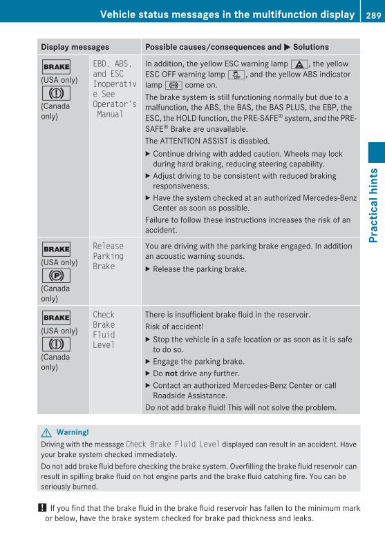
Display messages Possible causes/consequences and M Solutions
$(USA only)J(Canadaonly)
EBD, ABS, and ESC Inoperative See Operator's Manual
In addition, the yellow ESC warning lamp ä, the yellowESC OFF warning lamp å, and the yellow ABS indicatorlamp ! come on.The brake system is still functioning normally but due to amalfunction, the ABS, the BAS, the BAS PLUS, the EBP, theESC, the HOLD function, the PRE-SAFE® system, and the PRE-SAFE® Brake are unavailable.The ATTENTION ASSIST is disabled.X Continue driving with added caution. Wheels may lock
during hard braking, reducing steering capability.X Adjust driving to be consistent with reduced braking
responsiveness.X Have the system checked at an authorized Mercedes-Benz
Center as soon as possible.Failure to follow these instructions increases the risk of anaccident.
$(USA only)!(Canadaonly)
Release Parking Brake
You are driving with the parking brake engaged. In additionan acoustic warning sounds.X Release the parking brake.
$(USA only)J(Canadaonly)
Check Brake Fluid Level
There is insufficient brake fluid in the reservoir.Risk of accident!X Stop the vehicle in a safe location or as soon as it is safe
to do so.X Engage the parking brake.X Do not drive any further.X Contact an authorized Mercedes-Benz Center or call
Roadside Assistance.Do not add brake fluid! This will not solve the problem.
G Warning!Driving with the message Check Brake Fluid Level displayed can result in an accident. Haveyour brake system checked immediately.Do not add brake fluid before checking the brake system. Overfilling the brake fluid reservoir canresult in spilling brake fluid on hot engine parts and the brake fluid catching fire. You can beseriously burned.
! If you find that the brake fluid in the brake fluid reservoir has fallen to the minimum markor below, have the brake system checked for brake pad thickness and leaks.
Vehicle status messages in the multifunction display 289
Prac
tical
hin
ts
212_AKB; 2; 41, en-USd2ureepe, Version: 2.11.8.1
2009-07-17T09:14:21+02:00 - Seite 289
Z
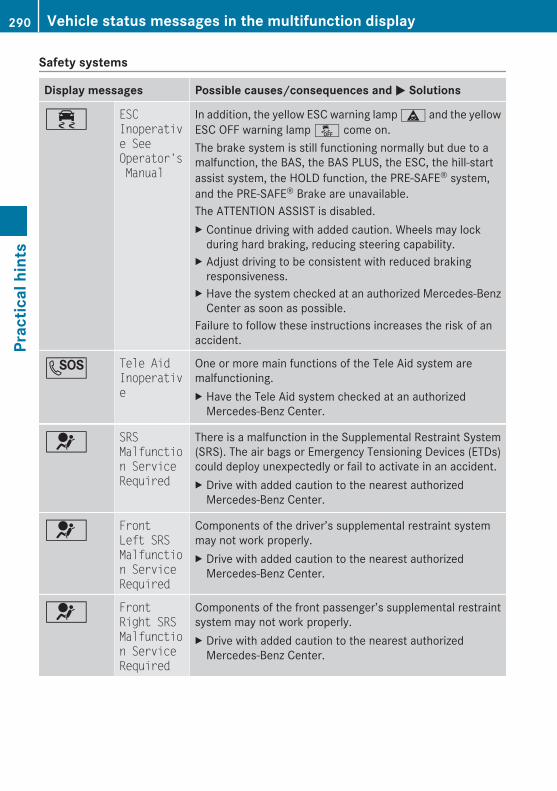
Safety systems
Display messages Possible causes/consequences and M Solutions
÷ ESC Inoperative See Operator's Manual
In addition, the yellow ESC warning lamp ä and the yellowESC OFF warning lamp å come on.The brake system is still functioning normally but due to amalfunction, the BAS, the BAS PLUS, the ESC, the hill-startassist system, the HOLD function, the PRE-SAFE® system,and the PRE-SAFE® Brake are unavailable.The ATTENTION ASSIST is disabled.X Continue driving with added caution. Wheels may lock
during hard braking, reducing steering capability.X Adjust driving to be consistent with reduced braking
responsiveness.X Have the system checked at an authorized Mercedes-Benz
Center as soon as possible.Failure to follow these instructions increases the risk of anaccident.
G Tele Aid Inoperative
One or more main functions of the Tele Aid system aremalfunctioning.X Have the Tele Aid system checked at an authorized
Mercedes-Benz Center.
6 SRS Malfunction Service Required
There is a malfunction in the Supplemental Restraint System(SRS). The air bags or Emergency Tensioning Devices (ETDs)could deploy unexpectedly or fail to activate in an accident.X Drive with added caution to the nearest authorized
Mercedes-Benz Center.
6 Front Left SRS Malfunction Service Required
Components of the driver’s supplemental restraint systemmay not work properly.X Drive with added caution to the nearest authorized
Mercedes-Benz Center.
6 Front Right SRS Malfunction Service Required
Components of the front passenger’s supplemental restraintsystem may not work properly.X Drive with added caution to the nearest authorized
Mercedes-Benz Center.
290 Vehicle status messages in the multifunction displayPr
actic
al h
ints
212_AKB; 2; 41, en-USd2ureepe, Version: 2.11.8.1
2009-07-17T09:14:21+02:00 - Seite 290

Display messages Possible causes/consequences and M Solutions
6 Rear Left SRS Malfunction Service Required
Components of the left rear passenger’s supplementalrestraint system may not work properly.X Drive with added caution to the nearest authorized
Mercedes-Benz Center.
6 Rear Center SRS Malfunction Service Required
Components of the center rear passenger’s supplementalrestraint system may not work properly.X Drive with added caution to the nearest authorized
Mercedes-Benz Center.
6 Rear Right SRS Malfunction Service Required
Components of the right rear passenger’s supplementalrestraint system may not work properly.X Drive with added caution to the nearest authorized
Mercedes-Benz Center.
6 Left Side Curtain Airbag Malfunction Service Required
The left window curtain air bag may not work properly.X Drive with added caution to the nearest authorized
Mercedes-Benz Center.
6 Right Side Curtain Airbag Malfunction Service Required
The right window curtain air bag may not work properly.X Drive with added caution to the nearest authorized
Mercedes-Benz Center.
G Warning!In the event a malfunction of the SRS isindicated as outlined above, the SRS may notbe operational.For your safety, we strongly recommend thatyou contact an authorized Mercedes-Benz
Center immediately to have the systemchecked. Otherwise the SRS may not beactivated when needed in an accident, whichcould result in serious or fatal injury, or itmight deploy unexpectedly and unnecessarilywhich could also result in injury.
Vehicle status messages in the multifunction display 291
Prac
tical
hin
ts
212_AKB; 2; 41, en-USd2ureepe, Version: 2.11.8.1
2009-07-17T09:14:21+02:00 - Seite 291
Z
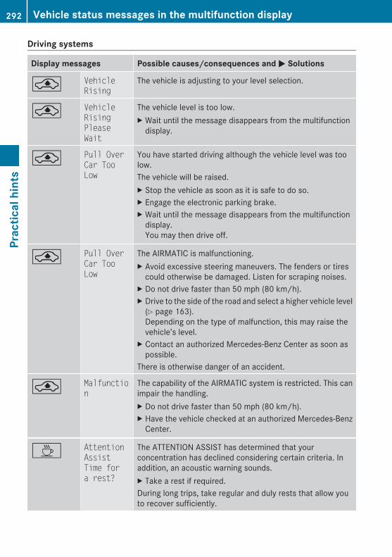
Driving systems
Display messages Possible causes/consequences and M Solutions
¨ Vehicle Rising
The vehicle is adjusting to your level selection.
¨ Vehicle Rising Please Wait
The vehicle level is too low.X Wait until the message disappears from the multifunction
display.
¨ Pull Over Car Too Low
You have started driving although the vehicle level was toolow.The vehicle will be raised.X Stop the vehicle as soon as it is safe to do so.X Engage the electronic parking brake.X Wait until the message disappears from the multifunction
display.You may then drive off.
¨ Pull Over Car Too Low
The AIRMATIC is malfunctioning.X Avoid excessive steering maneuvers. The fenders or tires
could otherwise be damaged. Listen for scraping noises.X Do not drive faster than 50 mph (80 km/h).X Drive to the side of the road and select a higher vehicle level
(Y page 163).Depending on the type of malfunction, this may raise thevehicle’s level.
X Contact an authorized Mercedes-Benz Center as soon aspossible.
There is otherwise danger of an accident.
¨ Malfunction
The capability of the AIRMATIC system is restricted. This canimpair the handling.X Do not drive faster than 50 mph (80 km/h).X Have the vehicle checked at an authorized Mercedes-Benz
Center.
À Attention Assist Time for a rest?
The ATTENTION ASSIST has determined that yourconcentration has declined considering certain criteria. Inaddition, an acoustic warning sounds.X Take a rest if required.During long trips, take regular and duly rests that allow youto recover sufficiently.
292 Vehicle status messages in the multifunction displayPr
actic
al h
ints
212_AKB; 2; 41, en-USd2ureepe, Version: 2.11.8.1
2009-07-17T09:14:21+02:00 - Seite 292
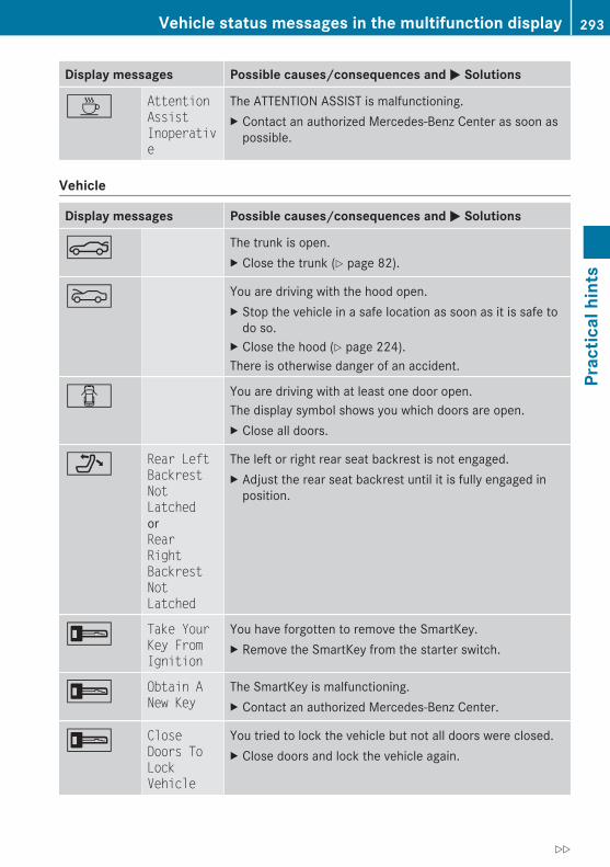
Display messages Possible causes/consequences and M Solutions
À Attention Assist Inoperative
The ATTENTION ASSIST is malfunctioning.X Contact an authorized Mercedes-Benz Center as soon as
possible.
Vehicle
Display messages Possible causes/consequences and M Solutions
N The trunk is open.X Close the trunk (Y page 82).
M You are driving with the hood open.X Stop the vehicle in a safe location as soon as it is safe to
do so.X Close the hood (Y page 224).There is otherwise danger of an accident.
C You are driving with at least one door open.The display symbol shows you which doors are open.X Close all doors.
_ Rear Left Backrest Not LatchedorRear Right Backrest Not Latched
The left or right rear seat backrest is not engaged.X Adjust the rear seat backrest until it is fully engaged in
position.
+ Take Your Key From Ignition
You have forgotten to remove the SmartKey.X Remove the SmartKey from the starter switch.
+ Obtain A New Key
The SmartKey is malfunctioning.X Contact an authorized Mercedes-Benz Center.
+ Close Doors To Lock Vehicle
You tried to lock the vehicle but not all doors were closed.X Close doors and lock the vehicle again.
Vehicle status messages in the multifunction display 293
Prac
tical
hin
ts
212_AKB; 2; 41, en-USd2ureepe, Version: 2.11.8.1
2009-07-17T09:14:21+02:00 - Seite 293
Z

Display messages Possible causes/consequences and M Solutions
+ Key Does Not Belong to Vehicle
The SmartKey in the starter switch does not belong to thevehicle.X Remove the SmartKey from the starter switch.
+ Replace Key Battery
The batteries in the SmartKey with KEYLESS-GO aredischarged.X Replace the batteries (Y page 317).
+ Key Not Detected(messageappears inred)
The SmartKey with KEYLESS-GO is not detected while theengine is running because the SmartKey is not in the vehicle.X Stop the vehicle as soon as it is safe to do so.X Engage the parking brake.X Search for the SmartKey.
The vehicle cannot be locked centrally nor can the enginebe started again after the engine is stopped.
+ Key Not Detected(messageappears inred)
The SmartKey with KEYLESS-GO is not detected while theengine is running because there is strong radio-frequencyinterference.X Stop the vehicle as soon as it is safe to do so.X Engage the parking brake.X Remove the KEYLESS-GO button from the starter switch
(Y page 86).X Operate the vehicle with the SmartKey in the starter switch.
+ Key Not Detected(messageappears inwhite)
The SmartKey with KEYLESS-GO is momentarily not detected.X Change the position of the SmartKey in the vehicle.X If necessary, remove the KEYLESS-GO button from the
starter switch (Y page 86).
+ Remove 'Start' Button and Insert Key
The KEYLESS-GO system is malfunctioning.X Remove the KEYLESS-GO button from the starter switch
(Y page 86).X Operate the vehicle with the SmartKey in the starter switch.
¥ Check Washer Fluid
The washer fluid in the washer fluid reservoir has fallen belowthe minimum level.X Add washer fluid (Y page 227).
294 Vehicle status messages in the multifunction displayPr
actic
al h
ints
212_AKB; 2; 41, en-USd2ureepe, Version: 2.11.8.1
2009-07-17T09:14:21+02:00 - Seite 294
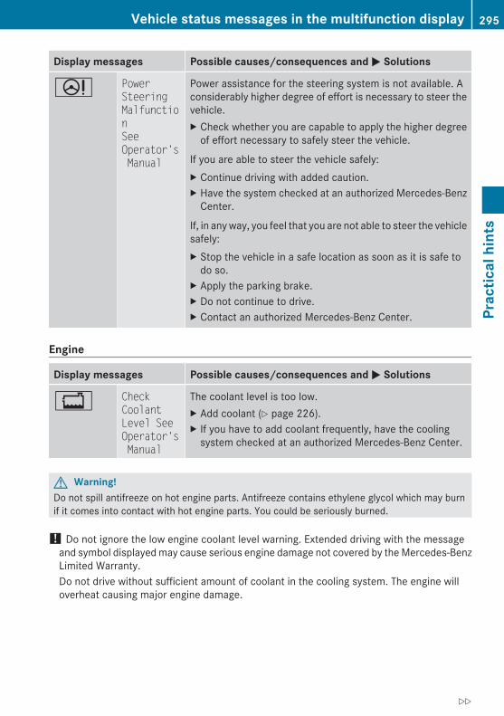
Display messages Possible causes/consequences and M Solutions
D Power SteeringMalfunctionSee Operator's Manual
Power assistance for the steering system is not available. Aconsiderably higher degree of effort is necessary to steer thevehicle.X Check whether you are capable to apply the higher degree
of effort necessary to safely steer the vehicle.
If you are able to steer the vehicle safely:X Continue driving with added caution.X Have the system checked at an authorized Mercedes-Benz
Center.
If, in any way, you feel that you are not able to steer the vehiclesafely:X Stop the vehicle in a safe location as soon as it is safe to
do so.X Apply the parking brake.X Do not continue to drive.X Contact an authorized Mercedes-Benz Center.
Engine
Display messages Possible causes/consequences and M Solutions
+ Check Coolant Level See Operator's Manual
The coolant level is too low.X Add coolant (Y page 226).X If you have to add coolant frequently, have the cooling
system checked at an authorized Mercedes-Benz Center.
G Warning!Do not spill antifreeze on hot engine parts. Antifreeze contains ethylene glycol which may burnif it comes into contact with hot engine parts. You could be seriously burned.
! Do not ignore the low engine coolant level warning. Extended driving with the messageand symbol displayed may cause serious engine damage not covered by the Mercedes-BenzLimited Warranty.Do not drive without sufficient amount of coolant in the cooling system. The engine willoverheat causing major engine damage.
Vehicle status messages in the multifunction display 295
Prac
tical
hin
ts
212_AKB; 2; 41, en-USd2ureepe, Version: 2.11.8.1
2009-07-17T09:14:21+02:00 - Seite 295
Z

Display messages Possible causes/consequences and M Solutions
? Coolant Low Stop Vehicle! Turn Engine Off
The coolant is too hot.X Stop the vehicle immediately as soon as it is safe to do so.X Turn off the engine immediately.X Engage the parking brake.X Only start the engine again after the message disappears.
You could otherwise damage the engine.X Observe the coolant temperature gauge in the instrument
cluster.X If the temperature rises again: Contact an authorized
Mercedes-Benz Center immediately.During severe operation conditions and stop-and-go citytraffic, the coolant temperature may rise close to 248‡(120†).
G Warning!Driving when your engine is overheated can cause some fluids which may have leaked into theengine compartment to catch fire. You could be seriously burned.Steam from an overheated engine can cause serious burns which can occur just by opening theengine hood. Stay away from the engine if you see or hear steam coming from it.Stop the vehicle in a safe location away from other traffic. Turn off the engine, get out of thevehicle and do not stand near the vehicle until the engine has cooled down.
! The engine should not be operated with the coolant temperature above 248‡ (120†).Doing so may cause serious damage which is not covered by the Mercedes-Benz LimitedWarranty.
296 Vehicle status messages in the multifunction displayPr
actic
al h
ints
212_AKB; 2; 41, en-USd2ureepe, Version: 2.11.8.1
2009-07-17T09:14:21+02:00 - Seite 296
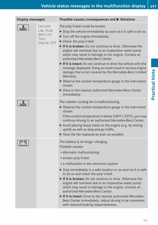
Display messages Possible causes/consequences and M Solutions
? Coolant Low Stop Vehicle! Turn Engine Off
The poly-V-belt could be broken.X Stop the vehicle immediately as soon as it is safe to do so.X Turn off the engine immediately.X Check the poly-V-belt.X If it is broken: Do not continue to drive. Otherwise the
engine will overheat due to an inoperative water pumpwhich may result in damage to the engine. Contact anauthorized Mercedes-Benz Center.
X If it is intact: Do not continue to drive the vehicle with thismessage displayed. Doing so could result in serious enginedamage that is not covered by the Mercedes-Benz LimitedWarranty.
X Observe the coolant temperature gauge in the instrumentcluster.
X Drive to the nearest authorized Mercedes-Benz Centerimmediately.
? The radiator cooling fan is malfunctioning.X Observe the coolant temperature gauge in the instrument
cluster.If the coolant temperature is below 248‡ (120†), you maycontinue driving to an authorized Mercedes-Benz Center.
X Avoid placing heavy loads on the engine (e.g. by drivinguphill) as well as stop-and-go traffic.
X Have the fan replaced as soon as possible.
# The battery is no longer charging.Possible causes:Ralternator malfunctioningRbroken poly-V-beltRa malfunction in the electronic systemX Stop immediately in a safe location or as soon as it is safe
to do so and check the poly-V-belt.X If it is broken: Do not continue to drive. Otherwise the
engine will overheat due to an inoperative water pumpwhich may result in damage to the engine. Contact anauthorized Mercedes-Benz Center.
X If it is intact: Drive to the nearest authorized Mercedes-Benz Center immediately. Adjust driving to be consistentwith reduced braking responsiveness.
Vehicle status messages in the multifunction display 297
Prac
tical
hin
ts
212_AKB; 2; 41, en-USd2ureepe, Version: 2.11.8.1
2009-07-17T09:14:21+02:00 - Seite 297
Z
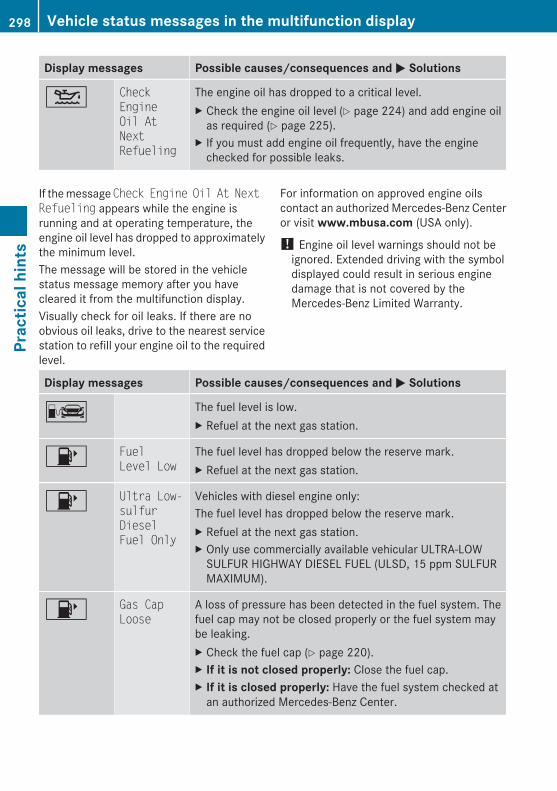
Display messages Possible causes/consequences and M Solutions
4 Check Engine Oil At Next Refueling
The engine oil has dropped to a critical level.X Check the engine oil level (Y page 224) and add engine oil
as required (Y page 225).X If you must add engine oil frequently, have the engine
checked for possible leaks.
If the message Check Engine Oil At Next Refueling appears while the engine isrunning and at operating temperature, theengine oil level has dropped to approximatelythe minimum level.The message will be stored in the vehiclestatus message memory after you havecleared it from the multifunction display.Visually check for oil leaks. If there are noobvious oil leaks, drive to the nearest servicestation to refill your engine oil to the requiredlevel.
For information on approved engine oilscontact an authorized Mercedes-Benz Centeror visit www.mbusa.com (USA only).
! Engine oil level warnings should not beignored. Extended driving with the symboldisplayed could result in serious enginedamage that is not covered by theMercedes-Benz Limited Warranty.
Display messages Possible causes/consequences and M Solutions
C The fuel level is low.X Refuel at the next gas station.
8 Fuel Level Low
The fuel level has dropped below the reserve mark.X Refuel at the next gas station.
8 Ultra Low-sulfur Diesel Fuel Only
Vehicles with diesel engine only:The fuel level has dropped below the reserve mark.X Refuel at the next gas station.X Only use commercially available vehicular ULTRA-LOW
SULFUR HIGHWAY DIESEL FUEL (ULSD, 15 ppm SULFURMAXIMUM).
8 Gas Cap Loose
A loss of pressure has been detected in the fuel system. Thefuel cap may not be closed properly or the fuel system maybe leaking.X Check the fuel cap (Y page 220).X If it is not closed properly: Close the fuel cap.X If it is closed properly: Have the fuel system checked at
an authorized Mercedes-Benz Center.
298 Vehicle status messages in the multifunction displayPr
actic
al h
ints
212_AKB; 2; 41, en-USd2ureepe, Version: 2.11.8.1
2009-07-17T09:14:21+02:00 - Seite 298
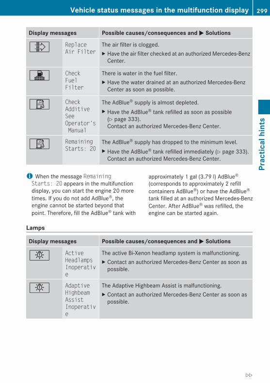
Display messages Possible causes/consequences and M Solutions
¸ Replace Air Filter
The air filter is clogged.X Have the air filter checked at an authorized Mercedes-Benz
Center.
! Check Fuel Filter
There is water in the fuel filter.X Have the water drained at an authorized Mercedes-Benz
Center as soon as possible.
Ø Check Additive See Operator's Manual
The AdBlue® supply is almost depleted.X Have the AdBlue® tank refilled as soon as possible
(Y page 333).Contact an authorized Mercedes-Benz Center.
Ø Remaining Starts: 20
The AdBlue® supply has dropped to the minimum level.X Have the AdBlue® tank refilled immediately (Y page 333).
Contact an authorized Mercedes-Benz Center.
i When the message Remaining Starts: 20 appears in the multifunctiondisplay, you can start the engine 20 moretimes. If you do not add AdBlue®, theengine cannot be started beyond thatpoint. Therefore, fill the AdBlue® tank with
approximately 1 gal (3.79 l) AdBlue®
(corresponds to approximately 2 refillcontainers AdBlue®) or have the AdBlue®
tank filled at an authorized Mercedes-BenzCenter. After AdBlue® was refilled, theengine can be started again.
Lamps
Display messages Possible causes/consequences and M Solutions
b Active Headlamps Inoperative
The active Bi-Xenon headlamp system is malfunctioning.X Contact an authorized Mercedes-Benz Center as soon as
possible.
b Adaptive Highbeam Assist Inoperative
The Adaptive Highbeam Assist is malfunctioning.X Contact an authorized Mercedes-Benz Center as soon as
possible.
Vehicle status messages in the multifunction display 299
Prac
tical
hin
ts
212_AKB; 2; 41, en-USd2ureepe, Version: 2.11.8.1
2009-07-17T09:14:21+02:00 - Seite 299
Z

Display messages Possible causes/consequences and M Solutions
b Check Left Daytime Running LightorCheck Right Daytime Running Light
The left or right daytime running lamps are malfunctioning.X Contact an authorized Mercedes-Benz Center as soon as
possible.
b Check Left Reverse LamporCheck Right Reverse Lamp
The left or right backup lamp is malfunctioning.X Contact an authorized Mercedes-Benz Center as soon as
possible.
b Check Center Brake Lamp
The high-mounted brake lamp is malfunctioning. Thismessage will only appear if all LEDs have stopped working.X Contact an authorized Mercedes-Benz Center as soon as
possible.
b Check Left Fog LamporCheck Right Fog Lamp
The left or right front fog lamp is malfunctioning. This messagewill only appear if all LEDs have stopped working.X Contact an authorized Mercedes-Benz Center as soon as
possible.
b Check Front Left Sidemarker LamporCheck Front Right Sidemarker Lamp
The front left side or right side marker lamp is malfunctioning.X Contact an authorized Mercedes-Benz Center as soon as
possible.
300 Vehicle status messages in the multifunction displayPr
actic
al h
ints
212_AKB; 2; 41, en-USd2ureepe, Version: 2.11.8.1
2009-07-17T09:14:21+02:00 - Seite 300
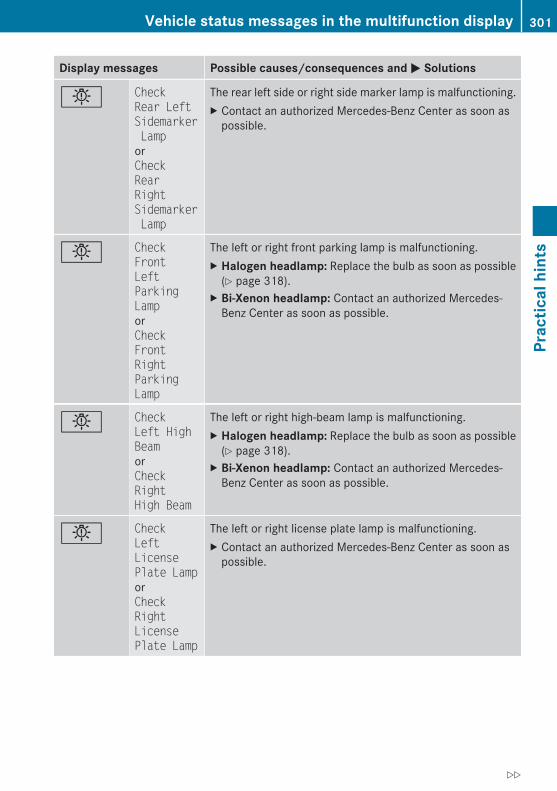
Display messages Possible causes/consequences and M Solutions
b Check Rear Left Sidemarker LamporCheck Rear Right Sidemarker Lamp
The rear left side or right side marker lamp is malfunctioning.X Contact an authorized Mercedes-Benz Center as soon as
possible.
b Check Front Left Parking LamporCheck Front Right Parking Lamp
The left or right front parking lamp is malfunctioning.X Halogen headlamp: Replace the bulb as soon as possible
(Y page 318).X Bi-Xenon headlamp: Contact an authorized Mercedes-
Benz Center as soon as possible.
b Check Left High BeamorCheck Right High Beam
The left or right high-beam lamp is malfunctioning.X Halogen headlamp: Replace the bulb as soon as possible
(Y page 318).X Bi-Xenon headlamp: Contact an authorized Mercedes-
Benz Center as soon as possible.
b Check Left License Plate LamporCheck Right License Plate Lamp
The left or right license plate lamp is malfunctioning.X Contact an authorized Mercedes-Benz Center as soon as
possible.
Vehicle status messages in the multifunction display 301
Prac
tical
hin
ts
212_AKB; 2; 41, en-USd2ureepe, Version: 2.11.8.1
2009-07-17T09:14:21+02:00 - Seite 301
Z

Display messages Possible causes/consequences and M Solutions
b Auto Lamp Function Inoperative
The light sensor is malfunctioning. The headlamps come onautomatically.X Contact an authorized Mercedes-Benz Center as soon as
possible.
To switch off the headlamps (U.S. vehicles only):X Switch off the daytime running lamp mode in the control
system (Y page 141).X Switch off the headlamps using the exterior lamp switch
(Y page 97).
b Check Left Low BeamorCheck Right Low Beam
The left or right low-beam lamp is malfunctioning.X Halogen headlamp: Replace the bulb as soon as possible
(Y page 318).X Bi-Xenon headlamp: Contact an authorized Mercedes-
Benz Center as soon as possible.
b Check Rear Left Fog Lamp
The rear fog lamp is malfunctioning. This message will onlyappear if all LEDs have stopped working.X Contact an authorized Mercedes-Benz Center as soon as
possible.
b Switch Off Lights
You have removed the SmartKey from the starter switch,opened the driver’s door and left the headlamps on orremoved the SmartKey with KEYLESS-GO from the vehicleand left the headlamps on.X Turn the exterior lamp switch to $ or c
(Y page 97).orX With the fog lamps switched on: Push in the exterior
lamp switch to its stop.
b Check Left Tail and Brake LampsorCheck Right Tail and Brake Lamps
The left or right tail lamp/brake lamp is malfunctioning. Thismessage will only appear if all LEDs have stopped working.X Contact an authorized Mercedes-Benz Center as soon as
possible.
302 Vehicle status messages in the multifunction displayPr
actic
al h
ints
212_AKB; 2; 41, en-USd2ureepe, Version: 2.11.8.1
2009-07-17T09:14:21+02:00 - Seite 302
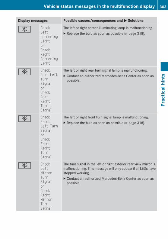
Display messages Possible causes/consequences and M Solutions
b Check Left Cornering LightorCheck Right Cornering Light
The left or right corner-illuminating lamp is malfunctioning.X Replace the bulb as soon as possible (Y page 318).
b Check Rear Left Turn SignalorCheck Rear Right Turn Signal
The left or right rear turn signal lamp is malfunctioning.X Contact an authorized Mercedes-Benz Center as soon as
possible.
b Check Front Left Turn SignalorCheck Front Right Turn Signal
The left or right front turn signal lamp is malfunctioning.X Replace the bulb as soon as possible (Y page 318).
b Check Left Mirror Turn SignalorCheck Right Mirror Turn Signal
The turn signal in the left or right exterior rear view mirror ismalfunctioning. This message will only appear if all LEDs havestopped working.X Contact an authorized Mercedes-Benz Center as soon as
possible.
Vehicle status messages in the multifunction display 303
Prac
tical
hin
ts
212_AKB; 2; 41, en-USd2ureepe, Version: 2.11.8.1
2009-07-17T09:14:21+02:00 - Seite 303
Z
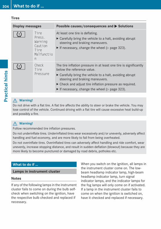
Tires
Display messages Possible causes/consequences and M Solutions
h Tire Press. Warning Caution Tire Malfunction
At least one tire is deflating.X Carefully bring the vehicle to a halt, avoiding abrupt
steering and braking maneuvers.X If necessary, change the wheel (Y page 323).
h Check Tire Pressure
The tire inflation pressure in at least one tire is significantlybelow the reference value.X Carefully bring the vehicle to a halt, avoiding abrupt
steering and braking maneuvers.X Check and adjust tire inflation pressure as required.X If necessary, change the wheel (Y page 323).
G Warning!Do not drive with a flat tire. A flat tire affects the ability to steer or brake the vehicle. You maylose control of the vehicle. Continued driving with a flat tire will cause excessive heat build-upand possibly a fire.
G Warning!Follow recommended tire inflation pressures.Do not underinflate tires. Underinflated tires wear excessively and/or unevenly, adversely affecthandling and fuel economy, and are more likely to fail from being overheated.Do not overinflate tires. Overinflated tires can adversely affect handling and ride comfort, wearunevenly, increase stopping distance, and result in sudden deflation (blowout) because they aremore likely to become punctured or damaged by road debris, potholes etc.
What to do if …
Lamps in instrument cluster
NotesIf any of the following lamps in the instrumentcluster fails to come on during the bulb self-check when switching on the ignition, havethe respective bulb checked and replaced ifnecessary.
When you switch on the ignition, all lamps inthe instrument cluster come on. The low-beam headlamp indicator lamp, high-beamheadlamp indicator lamp, turn signalindicator lamps, and the indicator lamps forthe fog lamps will only come on if activated.If a lamp in the instrument cluster fails tocome on when the ignition is switched on,have it checked and replaced if necessary.
304 What to do if …Pr
actic
al h
ints
212_AKB; 2; 41, en-USd2ureepe, Version: 2.11.8.1
2009-07-17T09:14:21+02:00 - Seite 304
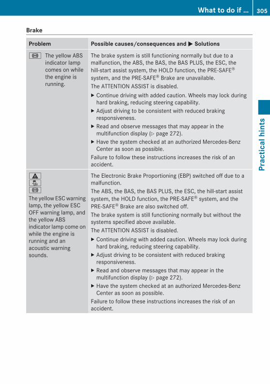
Brake
Problem Possible causes/consequences and M Solutions
! The yellow ABSindicator lampcomes on whilethe engine isrunning.
The brake system is still functioning normally but due to amalfunction, the ABS, the BAS, the BAS PLUS, the ESC, thehill-start assist system, the HOLD function, the PRE-SAFE®
system, and the PRE-SAFE® Brake are unavailable.The ATTENTION ASSIST is disabled.X Continue driving with added caution. Wheels may lock during
hard braking, reducing steering capability.X Adjust driving to be consistent with reduced braking
responsiveness.X Read and observe messages that may appear in the
multifunction display (Y page 272).X Have the system checked at an authorized Mercedes-Benz
Center as soon as possible.Failure to follow these instructions increases the risk of anaccident.
äå!
The yellow ESC warninglamp, the yellow ESCOFF warning lamp, andthe yellow ABSindicator lamp come onwhile the engine isrunning and anacoustic warningsounds.
The Electronic Brake Proportioning (EBP) switched off due to amalfunction.The ABS, the BAS, the BAS PLUS, the ESC, the hill-start assistsystem, the HOLD function, the PRE-SAFE® system, and thePRE-SAFE® Brake are also switched off.The brake system is still functioning normally but without thesystems specified above available.The ATTENTION ASSIST is disabled.X Continue driving with added caution. Wheels may lock during
hard braking, reducing steering capability.X Adjust driving to be consistent with reduced braking
responsiveness.X Read and observe messages that may appear in the
multifunction display (Y page 272).X Have the system checked at an authorized Mercedes-Benz
Center as soon as possible.Failure to follow these instructions increases the risk of anaccident.
What to do if … 305
Prac
tical
hin
ts
212_AKB; 2; 41, en-USd2ureepe, Version: 2.11.8.1
2009-07-17T09:14:21+02:00 - Seite 305
Z
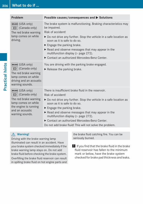
Problem Possible causes/consequences and M Solutions
$ (USA only)J (Canada only)The red brake warninglamp comes on whiledriving.
The brake system is malfunctioning. Braking characteristics maybe impaired.Risk of accident!X Do not drive any further. Stop the vehicle in a safe location as
soon as it is safe to do so.X Engage the parking brake.X Read and observe messages that may appear in the
multifunction display (Y page 272).X Contact an authorized Mercedes-Benz Center.
$ (USA only)J (Canada only)The red brake warninglamp comes on whiledriving and an acousticwarning sounds.
You are driving with the parking brake engaged.X Release the parking brake.
$ (USA only)J (Canada only)The red brake warninglamp comes on whilethe engine is runningand an acousticwarning sounds.
There is insufficient brake fluid in the reservoir.Risk of accident!X Do not drive any further. Stop the vehicle in a safe location as
soon as it is safe to do so.X Engage the parking brake.X Read and observe messages that may appear in the
multifunction display (Y page 272).X Contact an authorized Mercedes-Benz Center.Do not add brake fluid! This will not solve the problem.
G Warning!Driving with the brake warning lampilluminated can result in an accident. Haveyour brake system checked immediately if thebrake warning lamp stays on. Do not addbrake fluid before checking the brake system.Overfilling the brake fluid reservoir can resultin spilling brake fluid on hot engine parts and
the brake fluid catching fire. You can beseriously burned.
! If you find that the brake fluid in the brakefluid reservoir has fallen to the minimummark or below, have the brake systemchecked for brake pad thickness and leaks.
306 What to do if …Pr
actic
al h
ints
212_AKB; 2; 41, en-USd2ureepe, Version: 2.11.8.1
2009-07-17T09:14:21+02:00 - Seite 306
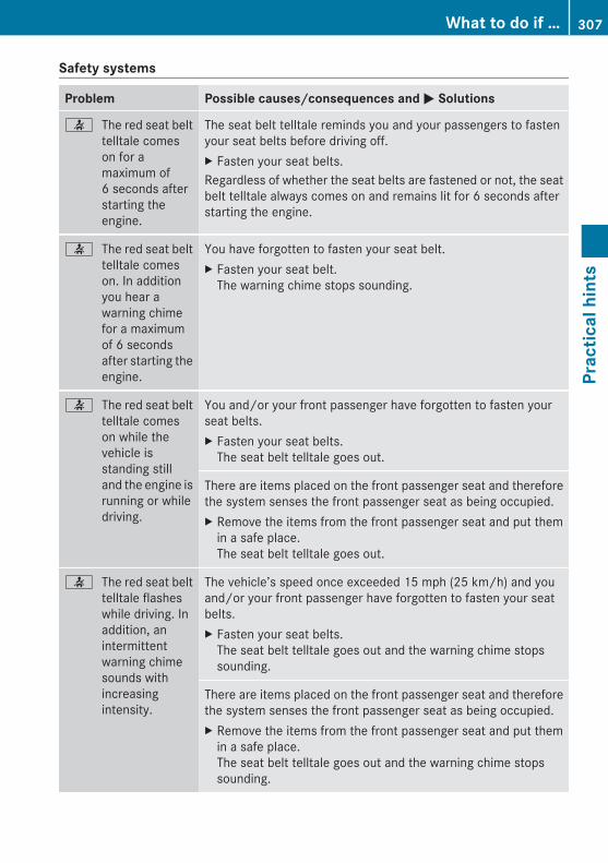
Safety systems
Problem Possible causes/consequences and M Solutions
7 The red seat belttelltale comeson for amaximum of6 seconds afterstarting theengine.
The seat belt telltale reminds you and your passengers to fastenyour seat belts before driving off.X Fasten your seat belts.Regardless of whether the seat belts are fastened or not, the seatbelt telltale always comes on and remains lit for 6 seconds afterstarting the engine.
7 The red seat belttelltale comeson. In additionyou hear awarning chimefor a maximumof 6 secondsafter starting theengine.
You have forgotten to fasten your seat belt.X Fasten your seat belt.
The warning chime stops sounding.
7 The red seat belttelltale comeson while thevehicle isstanding stilland the engine isrunning or whiledriving.
You and/or your front passenger have forgotten to fasten yourseat belts.X Fasten your seat belts.
The seat belt telltale goes out.
There are items placed on the front passenger seat and thereforethe system senses the front passenger seat as being occupied.X Remove the items from the front passenger seat and put them
in a safe place.The seat belt telltale goes out.
7 The red seat belttelltale flasheswhile driving. Inaddition, anintermittentwarning chimesounds withincreasingintensity.
The vehicle’s speed once exceeded 15 mph (25 km/h) and youand/or your front passenger have forgotten to fasten your seatbelts.X Fasten your seat belts.
The seat belt telltale goes out and the warning chime stopssounding.
There are items placed on the front passenger seat and thereforethe system senses the front passenger seat as being occupied.X Remove the items from the front passenger seat and put them
in a safe place.The seat belt telltale goes out and the warning chime stopssounding.
What to do if … 307
Prac
tical
hin
ts
212_AKB; 2; 41, en-USd2ureepe, Version: 2.11.8.1
2009-07-17T09:14:21+02:00 - Seite 307
Z
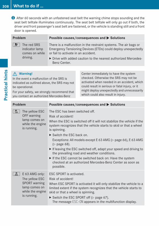
i After 60 seconds with an unfastened seat belt the warning chime stops sounding and theseat belt telltale illuminates continuously. The seat belt telltale will only go out if both, thedriver and front passenger’s seat belt are fastened, or the vehicle is standing still and a frontdoor is opened.
Problem Possible causes/consequences and M Solutions
6 The red SRSindicator lampcomes on whiledriving.
There is a malfunction in the restraint systems. The air bags orEmergency Tensioning Devices (ETDs) could deploy unexpectedlyor fail to activate in an accident.X Drive with added caution to the nearest authorized Mercedes-
Benz Center.
G Warning!In the event a malfunction of the SRS isindicated as outlined above, the SRS may notbe operational.For your safety, we strongly recommend thatyou contact an authorized Mercedes-Benz
Center immediately to have the systemchecked. Otherwise the SRS may not beactivated when needed in an accident, whichcould result in serious or fatal injury, or itmight deploy unexpectedly and unnecessarilywhich could also result in injury.
Problem Possible causes/consequences and M Solutions
å The yellow ESCOFF warninglamp comes onwhile the engineis running.
The ESC has been switched off.Risk of accident!When the ESC is switched off it will not stabilize the vehicle if thesystem recognizes that the vehicle starts to skid or that a wheelis spinning.X Switch the ESC back on.
Exceptions: All models except E 63 AMG (Y page 66), E 63 AMG(Y page 68).
X If leaving the ESC switched off, adapt your speed and driving tothe prevailing road and weather conditions.
X If the ESC cannot be switched back on: Have the systemchecked at an authorized Mercedes-Benz Center as soon aspossible.
ì E 63 AMG only:The yellow ESCSPORT warninglamp comes onwhile the engineis running.
ESC SPORT is activated.Risk of accident!When ESC SPORT is activated it will only stabilize the vehicle to alimited extent if the system recognizes that the vehicle starts toskid or that a wheel is spinning.X Switch the ESC SPORT off (Y page 67).
The message ESC-ON appears in the multifunction display.
308 What to do if …Pr
actic
al h
ints
212_AKB; 2; 41, en-USd2ureepe, Version: 2.11.8.1
2009-07-17T09:14:21+02:00 - Seite 308
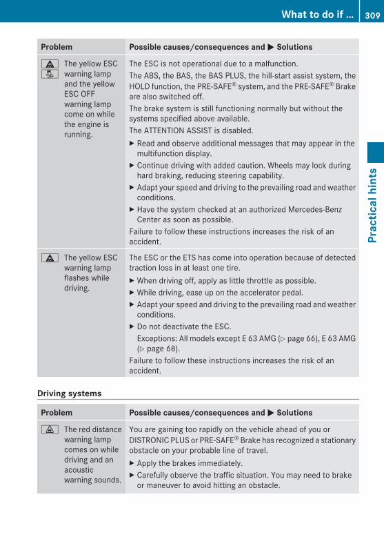
Problem Possible causes/consequences and M Solutions
äå
The yellow ESCwarning lampand the yellowESC OFFwarning lampcome on whilethe engine isrunning.
The ESC is not operational due to a malfunction.The ABS, the BAS, the BAS PLUS, the hill-start assist system, theHOLD function, the PRE-SAFE® system, and the PRE-SAFE® Brakeare also switched off.The brake system is still functioning normally but without thesystems specified above available.The ATTENTION ASSIST is disabled.X Read and observe additional messages that may appear in the
multifunction display.X Continue driving with added caution. Wheels may lock during
hard braking, reducing steering capability.X Adapt your speed and driving to the prevailing road and weather
conditions.X Have the system checked at an authorized Mercedes-Benz
Center as soon as possible.Failure to follow these instructions increases the risk of anaccident.
ä The yellow ESCwarning lampflashes whiledriving.
The ESC or the ETS has come into operation because of detectedtraction loss in at least one tire.X When driving off, apply as little throttle as possible.X While driving, ease up on the accelerator pedal.X Adapt your speed and driving to the prevailing road and weather
conditions.X Do not deactivate the ESC.
Exceptions: All models except E 63 AMG (Y page 66), E 63 AMG(Y page 68).
Failure to follow these instructions increases the risk of anaccident.
Driving systems
Problem Possible causes/consequences and M Solutions
· The red distancewarning lampcomes on whiledriving and anacousticwarning sounds.
You are gaining too rapidly on the vehicle ahead of you orDISTRONIC PLUS or PRE-SAFE® Brake has recognized a stationaryobstacle on your probable line of travel.X Apply the brakes immediately.X Carefully observe the traffic situation. You may need to brake
or maneuver to avoid hitting an obstacle.
What to do if … 309
Prac
tical
hin
ts
212_AKB; 2; 41, en-USd2ureepe, Version: 2.11.8.1
2009-07-17T09:14:21+02:00 - Seite 309
Z
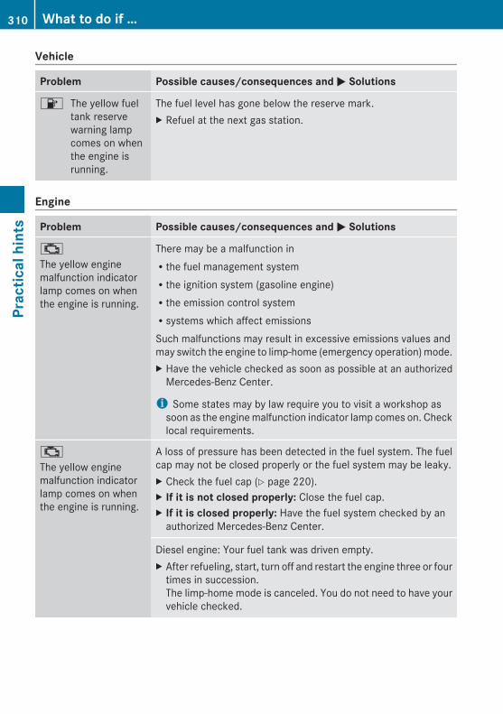
Vehicle
Problem Possible causes/consequences and M Solutions
8 The yellow fueltank reservewarning lampcomes on whenthe engine isrunning.
The fuel level has gone below the reserve mark.X Refuel at the next gas station.
Engine
Problem Possible causes/consequences and M Solutions
;
The yellow enginemalfunction indicatorlamp comes on whenthe engine is running.
There may be a malfunction inRthe fuel management systemRthe ignition system (gasoline engine)Rthe emission control systemRsystems which affect emissionsSuch malfunctions may result in excessive emissions values andmay switch the engine to limp-home (emergency operation) mode.X Have the vehicle checked as soon as possible at an authorized
Mercedes-Benz Center.
i Some states may by law require you to visit a workshop assoon as the engine malfunction indicator lamp comes on. Checklocal requirements.
;
The yellow enginemalfunction indicatorlamp comes on whenthe engine is running.
A loss of pressure has been detected in the fuel system. The fuelcap may not be closed properly or the fuel system may be leaky.X Check the fuel cap (Y page 220).X If it is not closed properly: Close the fuel cap.X If it is closed properly: Have the fuel system checked by an
authorized Mercedes-Benz Center.
Diesel engine: Your fuel tank was driven empty.X After refueling, start, turn off and restart the engine three or four
times in succession.The limp-home mode is canceled. You do not need to have yourvehicle checked.
310 What to do if …Pr
actic
al h
ints
212_AKB; 2; 41, en-USd2ureepe, Version: 2.11.8.1
2009-07-17T09:14:21+02:00 - Seite 310

Problem Possible causes/consequences and M Solutions
? The red coolanttemperaturewarning lampcomes on whenthe engine isrunning.
There is insufficient coolant in the reservoir.If this warning lamp comes on frequently, there is a leak in thecooling system.If the coolant level is correct, the electric radiator fan may bebroken.X Immediately add coolant to prevent engine from overheating
(Y page 226).X Have the cooling system checked.X If the coolant temperature is below 248‡ (120†), you can
continue driving to the nearest authorized Mercedes-BenzCenter.
X Avoid high engine loads (e.g. driving uphill) and stop-and-godriving.
? The red coolanttemperaturewarning lampcomes on whenthe engine isrunning and anacousticwarning sounds.
The coolant temperature has exceeded 248‡ (120†).X Stop in a safe location as soon as possible and allow the engine
and coolant to cool down.
G Warning!Driving when your engine is overheated cancause some fluids which may have leaked intothe engine compartment to catch fire. Youcould be seriously burned.Steam from an overheated engine can causeserious burns which can occur just by openingthe engine hood. Stay away from the engineif you see or hear steam coming from it.
Stop the vehicle in a safe location away fromother traffic. Turn off the engine, get out of thevehicle and do not stand near the vehicle untilthe engine has cooled down.
! The engine should not be operated withthe coolant temperature above 248‡(120†). Doing so may cause seriousdamage which is not covered by theMercedes-Benz Limited Warranty.
What to do if … 311
Prac
tical
hin
ts
212_AKB; 2; 41, en-USd2ureepe, Version: 2.11.8.1
2009-07-17T09:14:21+02:00 - Seite 311
Z
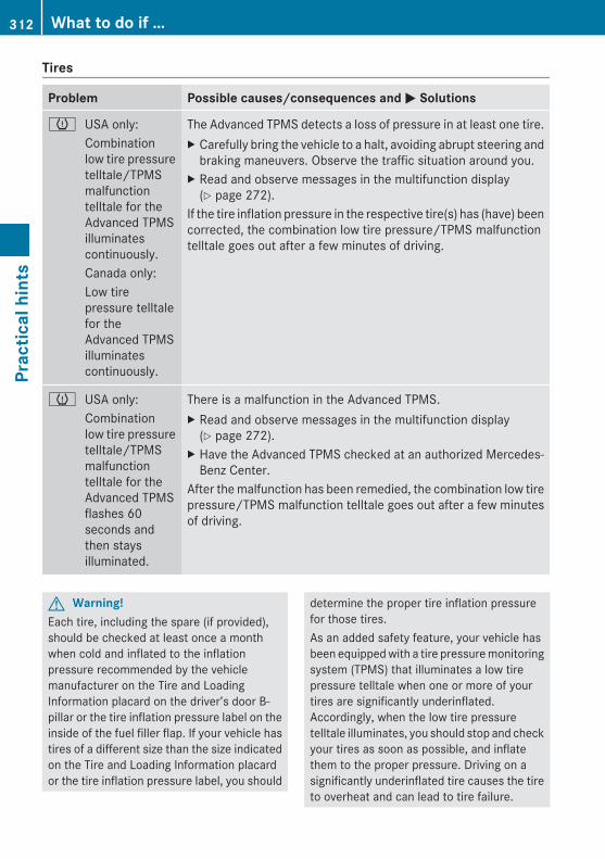
Tires
Problem Possible causes/consequences and M Solutions
h USA only:Combinationlow tire pressuretelltale/TPMSmalfunctiontelltale for theAdvanced TPMSilluminatescontinuously.Canada only:Low tirepressure telltalefor theAdvanced TPMSilluminatescontinuously.
The Advanced TPMS detects a loss of pressure in at least one tire.X Carefully bring the vehicle to a halt, avoiding abrupt steering and
braking maneuvers. Observe the traffic situation around you.X Read and observe messages in the multifunction display
(Y page 272).If the tire inflation pressure in the respective tire(s) has (have) beencorrected, the combination low tire pressure/TPMS malfunctiontelltale goes out after a few minutes of driving.
h USA only:Combinationlow tire pressuretelltale/TPMSmalfunctiontelltale for theAdvanced TPMSflashes 60seconds andthen staysilluminated.
There is a malfunction in the Advanced TPMS.X Read and observe messages in the multifunction display
(Y page 272).X Have the Advanced TPMS checked at an authorized Mercedes-
Benz Center.After the malfunction has been remedied, the combination low tirepressure/TPMS malfunction telltale goes out after a few minutesof driving.
G Warning!Each tire, including the spare (if provided),should be checked at least once a monthwhen cold and inflated to the inflationpressure recommended by the vehiclemanufacturer on the Tire and LoadingInformation placard on the driver’s door B-pillar or the tire inflation pressure label on theinside of the fuel filler flap. If your vehicle hastires of a different size than the size indicatedon the Tire and Loading Information placardor the tire inflation pressure label, you should
determine the proper tire inflation pressurefor those tires.As an added safety feature, your vehicle hasbeen equipped with a tire pressure monitoringsystem (TPMS) that illuminates a low tirepressure telltale when one or more of yourtires are significantly underinflated.Accordingly, when the low tire pressuretelltale illuminates, you should stop and checkyour tires as soon as possible, and inflatethem to the proper pressure. Driving on asignificantly underinflated tire causes the tireto overheat and can lead to tire failure.
312 What to do if …Pr
actic
al h
ints
212_AKB; 2; 41, en-USd2ureepe, Version: 2.11.8.1
2009-07-17T09:14:21+02:00 - Seite 312
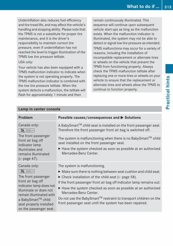
Underinflation also reduces fuel efficiencyand tire tread life, and may affect the vehicle’shandling and stopping ability. Please note thatthe TPMS is not a substitute for proper tiremaintenance, and it is the driver’sresponsibility to maintain correct tirepressure, even if underinflation has notreached the level to trigger illumination of theTPMS low tire pressure telltale.USA only:Your vehicle has also been equipped with aTPMS malfunction indicator to indicate whenthe system is not operating properly. TheTPMS malfunction indicator is combined withthe low tire pressure telltale. When thesystem detects a malfunction, the telltale willflash for approximately 1 minute and then
remain continuously illuminated. Thissequence will continue upon subsequentvehicle start-ups as long as the malfunctionexists. When the malfunction indicator isilluminated, the system may not be able todetect or signal low tire pressure as intended.TPMS malfunctions may occur for a variety ofreasons, including the installation ofincompatible replacement or alternate tiresor wheels on the vehicle that prevent theTPMS from functioning properly. Alwayscheck the TPMS malfunction telltale afterreplacing one or more tires or wheels on yourvehicle to ensure that the replacement oralternate tires and wheels allow the TPMS tocontinue to function properly.
Lamp in center console
Problem Possible causes/consequences and M Solutions
Canada only:45
The front passengerfront air bag offindicator lampilluminates andremains illuminated(Y page 47).
A BabySmartTM child seat is installed on the front passenger seat.Therefore the front passenger front air bag is switched off.
The system is malfunctioning when there is no BabySmartTM childseat installed on the front passenger seat.X Have the system checked as soon as possible at an authorized
Mercedes-Benz Center.
Canada only:45
The front passengerfront air bag offindicator lamp does notilluminate or does notremain illuminated witha BabySmartTM childseat properly installedon the passenger seat.
The system is malfunctioning.X Make sure there is nothing between seat cushion and child seat.X Check installation of the child seat (Y page 58).If the front passenger front air bag off indicator lamp remains out:X Have the system checked as soon as possible at an authorized
Mercedes-Benz Center.Do not use the BabySmartTM restraint to transport children on thefront passenger seat until the system has been repaired.
What to do if … 313
Prac
tical
hin
ts
212_AKB; 2; 41, en-USd2ureepe, Version: 2.11.8.1
2009-07-17T09:14:21+02:00 - Seite 313
Z

Problem Possible causes/consequences and M Solutions
USA only:45
The front passengerfront air bag offindicator lampilluminates andremains illuminatedwith the weight of atypical adult orsomeone larger than asmall individual on thefront passenger seat.
The system is malfunctioning.X Have the system checked as soon as possible at an authorized
Mercedes-Benz Center.X Read and observe messages in the multifunction display and
follow corrective steps (Y page 272).
G Warning!If the 45 indicator lamp illuminatesand remains illuminated with the weight of atypical adult or someone larger than a small
individual on the front passenger seat, do nothave any passenger use the front passengerseat until the system has been repaired.
Problem Possible causes/consequences and M Solutions
USA only:45
The front passengerfront air bag offindicator lamp does notilluminate and/or doesnot remain illuminatedwith the weight of atypical 12-month-oldchild in a standard childrestraint or less on thefront passenger seat.
The system is malfunctioning.X Make sure there is nothing between seat cushion and child seat
and check installation of the child seat.X Make sure no objects applying supplemental weight onto the
seat are present.X If the front passenger front air bag off indicator lamp remains
out, have the system checked as soon as possible at anauthorized Mercedes-Benz Center. Do not transport a child onthe front passenger seat until the system has been repaired.
X Read and observe messages in the multifunction display andfollow corrective steps (Y page 272).
G Warning!If the 45 indicator lamp does notilluminate or remains out with the weight of atypical 12-month-old child in a standard childrestraint or less on the front passenger seat,do not transport a child on the frontpassenger seat until the system has beenrepaired.
Unlocking/locking manually
Unlocking the vehicleIf you cannot unlock the vehicle with theSmartKey or with KEYLESS-GO, unlock thedriver’s door and the trunk using themechanical key.
314 Unlocking/locking manuallyPr
actic
al h
ints
212_AKB; 2; 41, en-USd2ureepe, Version: 2.11.8.1
2009-07-17T09:14:21+02:00 - Seite 314

The anti-theft alarm system will trigger whenyouRunlock the driver’s door or the trunk with
the mechanical keyandRopen the driver’s door or the trunkTo cancel the alarm, insert the SmartKey intothe starter switch.
Removing the mechanical key
X Move locking tab : in the direction ofarrow.
X Slide mechanical key ; out of the housing.
Unlocking the driver’s door
X Insert mechanical key ; into the driver’sdoor lock.
X Turn mechanical key ; counterclockwiseto position 1.
X Pull the door handle to open the driver’sdoor.
X Turn mechanical key ; back and removeit from the driver’s door lock.
Unlocking the trunk A minimum height clearance of 5.78 ft(1.76 m) is required to open the trunk lid.
X Insert mechanical key ; into the trunk lidlock.
X Turn mechanical key ; counterclockwiseto position 1.
! When you open the trunk, the trunk lidswings open upwards. Always make surethere is sufficient overhead clearance.
X Turn mechanical key ; back and removeit from the trunk lid lock.
Locking the vehicleIf you cannot lock the vehicle with theSmartKey or with KEYLESS-GO, lock it asfollows:X Open the driver’s door.X Close the front passenger door, the rear
doors, and the trunk.X Press the central locking switch
(Y page 81).The locking knobs of the front passengerdoor and the rear doors move down.
X If the vehicle battery is disconnected or drained: Press down the locking knobs on
Unlocking/locking manually 315
Prac
tical
hin
ts
212_AKB; 2; 41, en-USd2ureepe, Version: 2.11.8.1
2009-07-17T09:14:21+02:00 - Seite 315
Z

the front passenger door and the reardoors.
X Exit the vehicle.X Close the driver’s door.
X Remove mechanical key ; from theSmartKey (Y page 315).
X Insert mechanical key ; into the driver’sdoor lock.
X Turn mechanical key ; clockwise toposition 1.The vehicle is locked.
X Turn mechanical key ; back and removeit from the driver’s door lock.
X Check whether the doors and the trunk arelocked.
X If necessary, lock the trunk with themechanical key (Y page 85).
i This procedure does not arm the anti-theft alarm system, nor does it lock the fuelfiller flap.
Fuel filler flap
G Warning!Avoid contact with the vehicle walls as theymay contain sharp edges. Otherwise, youcould injure yourself while releasing the fuelfiller flap.
In case the central locking system does notrelease the fuel filler flap, you can open itmanually.
The fuel filler flap release is located on thepassenger side in the trunk behind the cover.X Open the trunk (Y page 81).X Push the parcel net down.X Open the cover (Y page 268).
X Remove fuel filler flap release ; fromholder :.
X Pull fuel filler flap release ; in direction ofthe arrow.
X Open the fuel filler flap (Y page 220).X Close the cover.X Close the trunk.
Resetting activated NECK-PRO active front head restraints
If the NECK-PRO active front head restraintshave been triggered in a rear-end collision,they must be reset.You can tell that the NECK-PRO active fronthead restraints have been triggered whenthey have been moved forward and cannot beadjusted.
G Warning!For safety reasons, have the NECK-PRO activefront head restraints checked at anauthorized Mercedes-Benz Center after arear-end collision.
316 Resetting activated NECK-PRO active front head restraintsPr
actic
al h
ints
212_AKB; 2; 41, en-USd2ureepe, Version: 2.11.8.1
2009-07-17T09:14:21+02:00 - Seite 316

G Warning!When pushing back the head restraintcushion, make sure your fingers do notbecome caught between the head restraintcushion and the cover. Failing to do so maylead to injury.
X Pull the top of the head restraint cushion indirection of arrow : as far as it will go.
X Adjust the head restraint cushiondownward in direction of arrow ; as far asit will go.
X Firmly press the top of the head restraintcushion towards the head restraint cover indirection of arrow = until it engages.
X Repeat this procedure on the NECK-PROactive front head restraint for the secondfront seat.
For information on NECK-PRO active fronthead restraints, see “NECK-PRO active fronthead restraints” (Y page 54).
Replacing SmartKey batteries
If the batteries in the SmartKey aredischarged, the vehicle can no longer belocked or unlocked. It is recommended tohave the batteries replaced at an authorizedMercedes-Benz Center.
G Warning!Batteries contain poisonous and corrosivesubstances. Therefore, keep the batteries outof reach of children.If a battery is swallowed, seek medical helpimmediately.
G Warning!SmartKey batteries contain perchloratematerial, which may require special handlingand regard for the environment. Check withyour local government’s disposal guidelines.California residents, see www.dtsc.ca.gov/HazardousWaste/Perchlorate/index.cfm.
Batteries contain materials that can harm theenvironment if disposed of improperly.Recycling of batteries is the preferred methodof disposal. Many states (USA only) orprovinces (Canada only) require sellers ofbatteries to accept old batteries for recycling.When inserting the batteries, make sure theyare clean and free of lint.When replacing batteries, always replaceboth batteries.
i The required replacement batteries areavailable at any authorized Mercedes-BenzCenter.
Replacement batteries: Lithium, typeCR 2025 or equivalent.X Remove the mechanical key from the
SmartKey (Y page 315).
Replacing SmartKey batteries 317
Prac
tical
hin
ts
212_AKB; 2; 41, en-USd2ureepe, Version: 2.11.8.1
2009-07-17T09:14:21+02:00 - Seite 317
Z

X Press mechanical key ; into the SmartKeyopening until battery compartmentcover : opens. Do not keep the covershut.
X Remove the battery compartment cover.X Pat the SmartKey against the palm of your
hand until battery = falls out.X Insert the new battery with the positive
terminal (+) facing up. Use a lint-free cloth.X Insert the tabs of the battery compartment
cover into the housing and press the coverclosed.
X Check the operation of the SmartKey aswell as the KEYLESS-GO function.
Replacing bulbs
Safety notesSafe vehicle operation depends on properexterior lighting and signaling to a largedegree.
Correct headlamp adjustment is extremelyimportant. Have headlamps checked andreadjusted at regular intervals and when abulb has been replaced. Contact anauthorized Mercedes-Benz Center forheadlamp adjustment.
G Warning!Bulbs and bulb sockets can be very hot. Allowthe lamp to cool down before changing a bulb.Keep bulbs out of reach of children.Halogen lamps contain pressurized gas. Abulb can explode if youRtouch or move it when hotRdrop the bulbRscratch the bulb
Wear eye and hand protection.Because of high voltage in Xenon lamps, it isdangerous to replace the bulb or repair thelamp and its components. We recommendthat you have such work done by a qualifiedtechnician.
i Since replacing bulbs is a technicallyhighly demanding process, we recommendto have them replaced at an authorizedMercedes-Benz Center.
i If the headlamps or front fog lamps arefogged up on the inside as a result of highhumidity, driving the vehicle a distance withthe lights on should clear up the fogging.
318 Replacing bulbsPr
actic
al h
ints
212_AKB; 2; 41, en-USd2ureepe, Version: 2.11.8.1
2009-07-17T09:14:21+02:00 - Seite 318
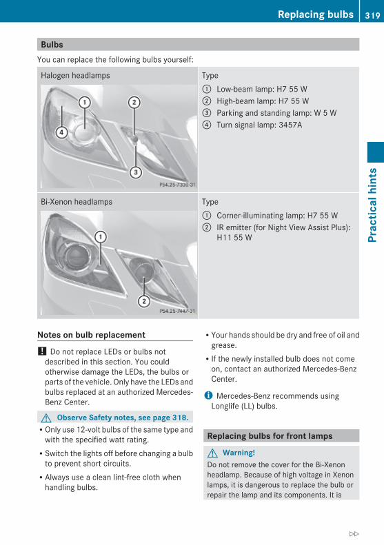
BulbsYou can replace the following bulbs yourself:
Halogen headlamps Type: Low-beam lamp: H7 55 W; High-beam lamp: H7 55 W= Parking and standing lamp: W 5 W? Turn signal lamp: 3457A
Bi-Xenon headlamps Type: Corner-illuminating lamp: H7 55 W; IR emitter (for Night View Assist Plus):
H11 55 W
Notes on bulb replacement! Do not replace LEDs or bulbs not
described in this section. You couldotherwise damage the LEDs, the bulbs orparts of the vehicle. Only have the LEDs andbulbs replaced at an authorized Mercedes-Benz Center.
G Observe Safety notes, see page 318.ROnly use 12-volt bulbs of the same type and
with the specified watt rating.RSwitch the lights off before changing a bulb
to prevent short circuits.RAlways use a clean lint-free cloth when
handling bulbs.
RYour hands should be dry and free of oil andgrease.RIf the newly installed bulb does not come
on, contact an authorized Mercedes-BenzCenter.
i Mercedes-Benz recommends usingLonglife (LL) bulbs.
Replacing bulbs for front lamps
G Warning!Do not remove the cover for the Bi-Xenonheadlamp. Because of high voltage in Xenonlamps, it is dangerous to replace the bulb orrepair the lamp and its components. It is
Replacing bulbs 319
Prac
tical
hin
ts
212_AKB; 2; 41, en-USd2ureepe, Version: 2.11.8.1
2009-07-17T09:14:21+02:00 - Seite 319
Z

recommended to have such work done by aqualified technician.
Before you start to replace a bulb for a frontlamp, do the following:X Switch off the ignition.X Turn the exterior lamp switch to position$.
X Open the hood (Y page 223).
Releasing/fixing the washer fluid reservoirTo replace bulbs of the driver’s sideheadlamp, the washer fluid reservoir in theengine compartment must be released.
X Releasing: Turn screw ;counterclockwise and remove it.
X Tilt washer fluid reservoir : to the side asfar as necessary to access the headlampbulbs.
X Fixing: Tilt washer fluid reservoir : backinto fixing position.
X Fasten screw ; by turning it clockwise.
Low beam (halogen headlamps only)
X Driver’s side only: Release the washer fluidreservoir (Y page 320).
X Turn housing cover : counterclockwiseand remove it.
X Turn bulb socket ; counterclockwise andpull it out.
X Pull the bulb out of bulb socket ;.X Insert the new bulb into bulb socket ;.X Insert bulb socket ; into the housing and
turn it clockwise.X Align housing cover : and turn it
clockwise.X Driver’s side only: Fix the washer fluid
reservoir (Y page 320).
High beam (halogen headlamps only) or Corner-illuminating lamp (Bi-Xenon headlamps only)
320 Replacing bulbsPr
actic
al h
ints
212_AKB; 2; 41, en-USd2ureepe, Version: 2.11.8.1
2009-07-17T09:14:21+02:00 - Seite 320

X Driver’s side only: Release the washer fluidreservoir (Y page 320).
X Turn housing cover : counterclockwiseand remove it.
X Turn bulb socket ; counterclockwise andpull it out.
X Pull the bulb out of bulb socket ;.X Insert the new bulb into bulb socket ;.X Insert bulb socket ; into the housing and
turn it clockwise.X Align housing cover : and turn it
clockwise.X Driver’s side only: Fix the washer fluid
reservoir (Y page 320).
Parking and standing lamp bulb (halogen headlamps only)
X Driver’s side only: Release the washer fluidreservoir (Y page 320).
X Turn housing cover : counterclockwiseand remove it.
X Pull out bulb socket ;.X Pull the bulb out of bulb socket ;.X Insert the new bulb into bulb socket ;.X Insert bulb socket ;.X Align housing cover : and turn it
clockwise.X Driver’s side only: Fix the washer fluid
reservoir (Y page 320).
IR emitter lamp bulb (Night View Assist Plus)
X Driver’s side only: Release the washer fluidreservoir (Y page 320).
X Turn housing cover : counterclockwiseand remove it.
X Turn bulb ; counterclockwise and pull itout.
X Insert bulb ; into the housing and turn itclockwise.
X Align housing cover : and turn itclockwise.
X Driver’s side only: Fix the washer fluidreservoir (Y page 320).
Front turn signal lamp bulb (halogen headlamps only)
X Driver’s side only: Release the washer fluidreservoir (Y page 320).
X Turn bulb socket : counterclockwise andpull it out.
Replacing bulbs 321
Prac
tical
hin
ts
212_AKB; 2; 41, en-USd2ureepe, Version: 2.11.8.1
2009-07-17T09:14:21+02:00 - Seite 321
Z
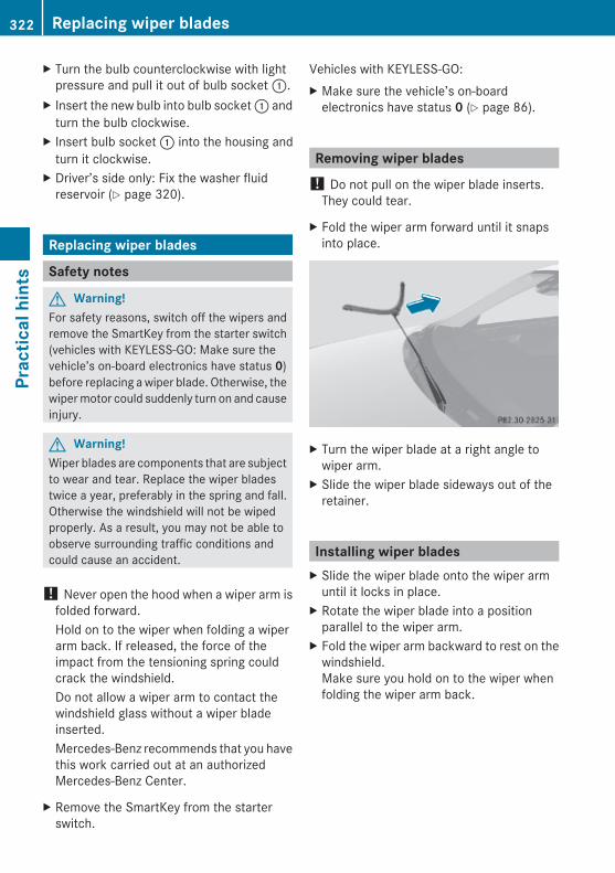
X Turn the bulb counterclockwise with lightpressure and pull it out of bulb socket :.
X Insert the new bulb into bulb socket : andturn the bulb clockwise.
X Insert bulb socket : into the housing andturn it clockwise.
X Driver’s side only: Fix the washer fluidreservoir (Y page 320).
Replacing wiper blades
Safety notes
G Warning!For safety reasons, switch off the wipers andremove the SmartKey from the starter switch(vehicles with KEYLESS-GO: Make sure thevehicle’s on-board electronics have status 0)before replacing a wiper blade. Otherwise, thewiper motor could suddenly turn on and causeinjury.
G Warning!Wiper blades are components that are subjectto wear and tear. Replace the wiper bladestwice a year, preferably in the spring and fall.Otherwise the windshield will not be wipedproperly. As a result, you may not be able toobserve surrounding traffic conditions andcould cause an accident.
! Never open the hood when a wiper arm isfolded forward.Hold on to the wiper when folding a wiperarm back. If released, the force of theimpact from the tensioning spring couldcrack the windshield.Do not allow a wiper arm to contact thewindshield glass without a wiper bladeinserted.Mercedes-Benz recommends that you havethis work carried out at an authorizedMercedes-Benz Center.
X Remove the SmartKey from the starterswitch.
Vehicles with KEYLESS-GO:X Make sure the vehicle’s on-board
electronics have status 0 (Y page 86).
Removing wiper blades! Do not pull on the wiper blade inserts.
They could tear.
X Fold the wiper arm forward until it snapsinto place.
X Turn the wiper blade at a right angle towiper arm.
X Slide the wiper blade sideways out of theretainer.
Installing wiper bladesX Slide the wiper blade onto the wiper arm
until it locks in place.X Rotate the wiper blade into a position
parallel to the wiper arm.X Fold the wiper arm backward to rest on the
windshield.Make sure you hold on to the wiper whenfolding the wiper arm back.
322 Replacing wiper bladesPr
actic
al h
ints
212_AKB; 2; 41, en-USd2ureepe, Version: 2.11.8.1
2009-07-17T09:14:21+02:00 - Seite 322

Flat tire
Safety notesYour vehicle may be equipped with:Ra Minispare wheelRa spare wheel with collapsible tireRan MOExtended system (your vehicle does
not have a spare wheel or a TIREFIT kit)Ra TIREFIT kit19 (your vehicle does not have
a spare wheel)
G Warning!The dimensions of the spare wheel aredifferent from those of the road wheels. As aresult, the vehicle handling characteristicschange when driving with a spare wheelmounted. Adapt your driving styleaccordingly.The spare wheel is for temporary use only.When driving with a spare wheel mounted,ensure proper tire inflation pressure and donot exceed a vehicle speed of 50 mph(80 km/h).Contact the nearest authorized Mercedes-Benz Center as soon as possible to have thespare wheel replaced with a regular roadwheel.Never operate the vehicle with more than onespare wheel mounted.Do not switch off the ESC when a spare wheelis mounted.
Preparing the vehicleX Vehicles with AIRMATIC:
Make sure the vehicle level is set to normallevel (Y page 163).
X Whenever possible, park the vehicle in asafe distance from moving traffic on a hard,flat surface.
X Turn on the hazard warning flasher.
X Turn the steering wheel so that the frontwheels are in a straight-ahead position.
X Engage the parking brake.X Shift the automatic transmission into park
position P.X Turn off the engine.X Remove the SmartKey from the starter
switch.orX Vehicles with KEYLESS-GO: Open the
driver’s door (this puts the starter switch inposition 0, same as with the SmartKeyremoved from the starter switch). Thedriver’s door can then be closed again.Open doors only when conditions are safeto do so.
X Vehicles with KEYLESS-GO: Remove theKEYLESS-GO start/stop button from thestarter switch.
X Have any passenger exit the vehicle at asafe distance from the roadway. Opendoors only when conditions are safe to doso.
Mounting the spare wheel
IntroductionX Prepare the vehicle as described
(Y page 323).X Take the following out of the vehicle:Rspare wheelRjackRvehicle tool kitRcollapsible wheel chockRelectric air pump (required for vehicles
with spare wheel with collapsible tireonly)
For information on where to find therespective items, see “Where will I find ...?”(Y page 268) and (Y page 271).
19 Canada only.
Flat tire 323
Prac
tical
hin
ts
212_AKB; 2; 41, en-USd2ureepe, Version: 2.11.8.1
2009-07-17T09:14:21+02:00 - Seite 323
Z

i Vehicles without spare wheel are notfactory-equipped with the tools required fora wheel change such as a jack or a wheelwrench. Some tools required for a wheelchange are specific to your vehicle.Contact an authorized Mercedes-BenzCenter to obtain the tools approved foryour vehicle. This section describes thewheel change using the tools approved andrecommended for your vehicle.
Lifting the vehicle
G Warning!When jacking up the vehicle, only use the jackwhich has been specifically approved byMercedes-Benz for your vehicle.The jack is designed exclusively for jacking upthe vehicle at the jack take-up brackets builtinto both sides of the vehicle. Make sure thejack arm is fully seated in the jack take-upbracket. The jack must always be verticalwhen in use, especially on inclines ordeclines.The jack is intended only for lifting the vehiclebriefly for wheel changes. It is not suited forperforming maintenance work under thevehicle. To help avoid personal injury, use thejack only to lift the vehicle during a wheelchange.Never get beneath the vehicle while it issupported by the jack. Keep hands and feetaway from the area under the lifted vehicle.Always lower the vehicle onto sufficientcapacity jackstands before working under thevehicle.Always engage the parking brake firmly andblock the wheels with wheel chocks or othersizeable objects before raising the vehiclewith the jack. Do not disengage the parkingbrake while the vehicle is raised.Make sure that the ground on which thevehicle is standing and where you place thejack is solid, level and not slippery. Ifnecessary, use a large underlay. On slippery
surfaces, such as tiled floors, you should usea non-slip underlay, for example a rubber mat.Do not use wooden blocks or similar objectsto support the jack. Otherwise the jack maynot be able to achieve its load-bearingcapacity if it is not at its full height.Never start the engine when the vehicle israised.Also observe the notes on the jack.
X Prevent the vehicle from rolling away byblocking wheels with wheel chocks or othersizeable objects.When your vehicle is equipped with a wheelchock, it is included with the vehicle tool kit(Y page 268). For information on setting upthe collapsible wheel chock, see(Y page 270).
When changing a wheel on a level surface:X Place a wheel chock or other sizeable
object in front of and another wheel chockor other sizeable object behind the wheelthat is diagonally opposite to the wheelbeing changed.
Always try lifting the vehicle using the jack ona level surface. However, shouldcircumstances require you to do so on a hill:X Place wheel chocks or other sizeable
objects on the downhill side in front of bothwheels on the side opposite to the side onwhich the wheel is to be changed.
G Warning!Only jack up the vehicle on level ground or onslight inclines/declines. Otherwise, thevehicle could fall off the jack and injure you orothers.
324 Flat tirePr
actic
al h
ints
212_AKB; 2; 41, en-USd2ureepe, Version: 2.11.8.1
2009-07-17T09:14:21+02:00 - Seite 324

X On the wheel to be changed, loosen but donot yet remove the wheel bolts(approximately one full turn with wheelwrench :).
The jack take-up brackets are located directlybehind the front wheel housings and in frontof the rear wheel housings.E 63 AMG and vehicles with AMG bodystyling: The respective cover in thedoor-sill trim must be removed to access thejack take-up brackets.
Example illustration: Vehicles with AMGbodystyling
X E 63 AMG and vehicles with AMG bodystyling: Remove cover ; in directionof arrow.
G Warning!The jack is designed exclusively for jacking upthe vehicle at the jack take-up brackets. Makesure the jack arm is fully seated in the jacktake-up bracket.If you do not position the jack correctly in thejack take-up bracket, the vehicle can fall off
the jack and seriously or fatally injure you orothers.
! Do not position the jack on the body ofthe vehicle, as this may cause damage tothe vehicle.
X Place jack ? on firm ground.X Position jack ? under take-up bracket= so that it is always vertical as seen fromthe side, even if the vehicle is parked on anincline.
X Turn crank A clockwise until jack ? isfully seated in take-up bracket = and thejack base evenly meets the ground.
X Jack up the vehicle until the wheel is amaximum of 1.2 in (3 cm) from the ground.
Flat tire 325
Prac
tical
hin
ts
212_AKB; 2; 41, en-USd2ureepe, Version: 2.11.8.1
2009-07-17T09:14:21+02:00 - Seite 325
Z

Removing the wheel
! E 63 AMG with ceramic composite brake disk: The rim could strike theceramic composite brake disk whenremoving and attaching the spare wheel.The ceramic composite brake disk could bedamaged. Exercise appropriate care andhave a second person assist you if possibleor use a second alignment bolt.
X Unscrew the uppermost wheel bolt andremove it.
X Replace this wheel bolt with alignmentbolt :.
X Remove the remaining bolts.
! Do not place wheel bolts in sand or dirt.This could result in damage to the wheelbolts and wheel hub threads.
X Remove the wheel.
Attaching the spare wheel
G Warning!Vehicles with spare wheel with collapsible tireonly: Inflate collapsible tire only after thewheel is properly attached.Inflate the collapsible tire using the electricair pump before lowering the vehicle.
G Warning!Always replace wheel bolts that are damagedor rusted.Never apply oil or grease to wheel bolts.
Damaged wheel hub threads should berepaired immediately. Do not continue todrive under these circumstances! Contact anauthorized Mercedes-Benz Center or callRoadside Assistance.Incorrect wheel bolts or improperly tightenedwheel bolts can cause the wheel to come off.This could cause an accident. Make sure touse the correct wheel bolts.
G Warning!Only use genuine Mercedes-Benz wheel bolts.Other wheel bolts may come loose.Do not tighten the wheel bolts when thevehicle is raised. Otherwise the vehicle couldfall off the jack.
X Clean contact surfaces of wheel and wheelhub.
! To avoid paint damage, place wheel flatagainst hub and hold it there whileinstalling first wheel bolt.
! E 63 AMG with ceramic composite brake disk: The rim could strike theceramic composite brake disk whenremoving and attaching the spare wheel.The ceramic composite brake disk could bedamaged. Exercise appropriate care andhave a second person assist you if possibleor use a second alignment bolt.
Example illustration: All models except E 63 AMG.
326 Flat tirePr
actic
al h
ints
212_AKB; 2; 41, en-USd2ureepe, Version: 2.11.8.1
2009-07-17T09:14:21+02:00 - Seite 326
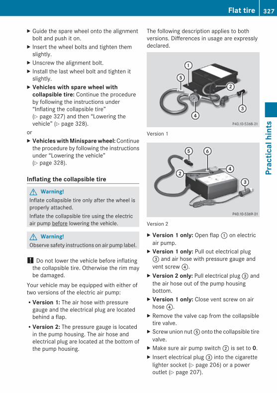
X Guide the spare wheel onto the alignmentbolt and push it on.
X Insert the wheel bolts and tighten themslightly.
X Unscrew the alignment bolt.X Install the last wheel bolt and tighten it
slightly.X Vehicles with spare wheel with
collapsible tire: Continue the procedureby following the instructions under“Inflating the collapsible tire”(Y page 327) and then “Lowering thevehicle” (Y page 328).
orX Vehicles with Minispare wheel: Continue
the procedure by following the instructionsunder “Lowering the vehicle”(Y page 328).
Inflating the collapsible tire
G Warning!Inflate collapsible tire only after the wheel isproperly attached.Inflate the collapsible tire using the electricair pump before lowering the vehicle.
G Warning!Observe safety instructions on air pump label.
! Do not lower the vehicle before inflatingthe collapsible tire. Otherwise the rim maybe damaged.
Your vehicle may be equipped with either oftwo versions of the electric air pump:RVersion 1: The air hose with pressure
gauge and the electrical plug are locatedbehind a flap.RVersion 2: The pressure gauge is located
in the pump housing. The air hose andelectrical plug are located at the bottom ofthe pump housing.
The following description applies to bothversions. Differences in usage are expresslydeclared.
Version 1
Version 2
X Version 1 only: Open flap : on electricair pump.
X Version 1 only: Pull out electrical plug= and air hose with pressure gauge andvent screw ?.
X Version 2 only: Pull electrical plug = andthe air hose out of the pump housingbottom.
X Version 1 only: Close vent screw on airhose ?.
X Remove the valve cap from the collapsibletire valve.
X Screw union nut A onto the collapsible tirevalve.
X Make sure air pump switch ; is set to 0.X Insert electrical plug = into the cigarette
lighter socket (Y page 206) or a poweroutlet (Y page 207).
Flat tire 327
Prac
tical
hin
ts
212_AKB; 2; 41, en-USd2ureepe, Version: 2.11.8.1
2009-07-17T09:14:21+02:00 - Seite 327
Z

X Turn the SmartKey in the starter switch toposition 1.
orX Vehicles with KEYLESS-GO: Press the
KEYLESS-GO start/stop button once. Donot depress the brake pedal.
X Press I on electric air pump switch ;.The electric air pump switches on andinflates the collapsible tire.
X Inflate the collapsible tire to therecommended tire inflation pressure asspecified for your vehicle (Y page 358).This should take approximately 5 minutes.
G Warning!The air hose and the union nut can becomehot during inflation. Exercise proper cautionto avoid burning yourself when using theequipment.
! Do not operate the electric air pumplonger than 8 minutes without interruption.Otherwise it may overheat.You may operate the air pump again afterit has cooled off.
! Compare the recommended tire inflationpressure for your vehicle with the tireinflation pressure on the yellow labellocated on the spare wheel rim.If the tire inflation pressure on the yellowlabel on the spare wheel rim differs fromthe values given in this Operator’s Manual,inflate the tire to the recommended tireinflation pressure given on the yellow labelon the spare wheel rim.
X Press 0 on electric air pump switch ;.X Turn the SmartKey in the starter switch to
position 0.orX Vehicles with KEYLESS-GO: Press the
KEYLESS-GO start/stop button twice. Donot depress the brake pedal.
X Version 1 only: If the tire inflation pressureis above the recommended tire inflation
pressure as specified for your vehicle(Y page 358), decrease tire pressure usingthe vent screw on air hose ?.
X Version 2 only: If the tire inflation pressureis above the recommended tire inflationpressure as specified for your vehicle(Y page 358), decrease tire pressure usingdeflate button B.
G Observe Safety notes, see page 231.X Detach the electric air pump.X Reinstall collapsible tire valve cap.X Version 1 only: Store electrical plug =
and air hose ? behind flap :.X Version 2 only: Store electrical plug =
and the air hose back into the pumphousing bottom.
X Place the electric air pump back in itsdesignated storage space.
X Lower the vehicle.
Lowering the vehicleX Lower the vehicle by turning the crank
counterclockwise until the vehicle isresting fully on its own weight.
X Remove the jack.
X Tighten the five wheel bolts evenly,following the diagonal sequence illustrated(: to A), until all bolts are tight. Observea tightening torque of 96 lb-ft (130 Nm).
328 Flat tirePr
actic
al h
ints
212_AKB; 2; 41, en-USd2ureepe, Version: 2.11.8.1
2009-07-17T09:14:21+02:00 - Seite 328
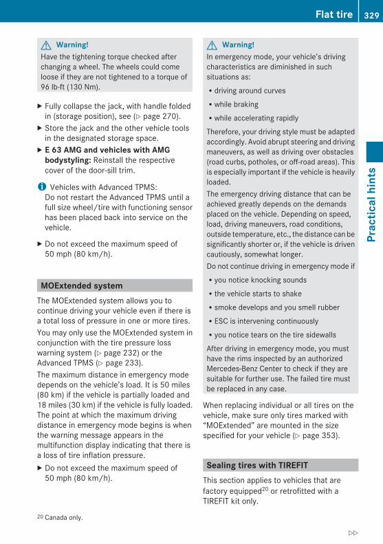
G Warning!Have the tightening torque checked afterchanging a wheel. The wheels could comeloose if they are not tightened to a torque of96 lb-ft (130 Nm).
X Fully collapse the jack, with handle foldedin (storage position), see (Y page 270).
X Store the jack and the other vehicle toolsin the designated storage space.
X E 63 AMG and vehicles with AMG bodystyling: Reinstall the respectivecover of the door-sill trim.
i Vehicles with Advanced TPMS:Do not restart the Advanced TPMS until afull size wheel/tire with functioning sensorhas been placed back into service on thevehicle.
X Do not exceed the maximum speed of50 mph (80 km/h).
MOExtended systemThe MOExtended system allows you tocontinue driving your vehicle even if there isa total loss of pressure in one or more tires.You may only use the MOExtended system inconjunction with the tire pressure losswarning system (Y page 232) or theAdvanced TPMS (Y page 233).The maximum distance in emergency modedepends on the vehicle’s load. It is 50 miles(80 km) if the vehicle is partially loaded and18 miles (30 km) if the vehicle is fully loaded.The point at which the maximum drivingdistance in emergency mode begins is whenthe warning message appears in themultifunction display indicating that there isa loss of tire inflation pressure.X Do not exceed the maximum speed of
50 mph (80 km/h).
G Warning!In emergency mode, your vehicle’s drivingcharacteristics are diminished in suchsituations as:Rdriving around curvesRwhile brakingRwhile accelerating rapidly
Therefore, your driving style must be adaptedaccordingly. Avoid abrupt steering and drivingmaneuvers, as well as driving over obstacles(road curbs, potholes, or off-road areas). Thisis especially important if the vehicle is heavilyloaded.The emergency driving distance that can beachieved greatly depends on the demandsplaced on the vehicle. Depending on speed,load, driving maneuvers, road conditions,outside temperature, etc., the distance can besignificantly shorter or, if the vehicle is drivencautiously, somewhat longer.Do not continue driving in emergency mode ifRyou notice knocking soundsRthe vehicle starts to shakeRsmoke develops and you smell rubberRESC is intervening continuouslyRyou notice tears on the tire sidewalls
After driving in emergency mode, you musthave the rims inspected by an authorizedMercedes-Benz Center to check if they aresuitable for further use. The failed tire mustbe replaced in any case.
When replacing individual or all tires on thevehicle, make sure only tires marked with“MOExtended” are mounted in the sizespecified for your vehicle (Y page 353).
Sealing tires with TIREFITThis section applies to vehicles that arefactory equipped20 or retrofitted with aTIREFIT kit only.
20 Canada only.
Flat tire 329
Prac
tical
hin
ts
212_AKB; 2; 41, en-USd2ureepe, Version: 2.11.8.1
2009-07-17T09:14:21+02:00 - Seite 329
Z

Small tire punctures, particularly those in thetread, can be sealed with TIREFIT.TIREFIT can be used in ambient temperaturesdown to -4‡ (-20†).
G Warning!TIREFIT is a limited repair device. TIREFITcannot be used for cuts or punctures largerthan approximately 0.16 in (4 mm) and tiredamage caused by driving with extremely lowtire inflation pressure, or on a flat tire, or adamaged wheel.Do not drive the vehicle under suchcircumstances.Contact the nearest authorized Mercedes-Benz Center for assistance or call RoadsideAssistance.
X Foreign objects (e.g. screws or nails)should not be removed from the tire.
X Take the TIREFIT kit, the sticker, and theelectric air pump out of the vehicle.
Two-part stickerX Attach upper part : of the sticker where
it will be easily seen by the driver on theinstrument cluster.
X Attach lower part ; of the sticker to thedamaged tire (close to the tire valve).
G Warning!Take care not to allow the contents of TIREFITto come in contact with hair, eyes or clothing.TIREFIT is harmful if inhaled, swallowed orabsorbed through the skin - causes skin, eyeand respiratory irritation.
Any contact with eyes or skin should beflushed immediately with plenty of water.If clothing comes in contact with TIREFIT,change clothing as soon as possible.In case of allergic reaction or rash, consult aphysician immediately.
G Warning!Keep TIREFIT out of reach of children. Ifswallowed, rinse mouth immediately withplenty of water and drink plenty of water.Do not induce vomiting!Consult a physician immediately.
i If sealant has leaked out, let it dry. Youcan then peel it off.If clothing has come in contact withTIREFIT, have it dry-cleaned withperchloroethylene as soon as possible.
G Warning!Observe safety instructions on air pump label.
Your vehicle may be equipped with either oftwo versions of the electric air pump:RVersion 1: The air hose with pressure
gauge and the electrical plug are locatedbehind a flap.RVersion 2: The pressure gauge is located
in the pump housing. The air hose andelectrical plug are located at the bottom ofthe pump housing.
The following description applies to bothversions. Differences in usage are expresslydeclared.
330 Flat tirePr
actic
al h
ints
212_AKB; 2; 41, en-USd2ureepe, Version: 2.11.8.1
2009-07-17T09:14:21+02:00 - Seite 330

Version 1
Version 2
X Version 1 only: Open flap C on theelectric air pump.
X Pull plug ? and air hose A out of the pumphousing.
X Screw the air pump’s air hose A ontoflange B of TIREFIT container :.
X Stick TIREFIT container : upside downinto notch ; of the electric air pump.
X Unscrew the valve cap of the damaged tirefrom tire valve E.
Version 1X Version 1 only: Close vent screw F on
pressure gauge G.X Screw filler hose D onto tire valve E.X Insert electrical plug ? into the cigarette
lighter socket (Y page 206) or a poweroutlet (Y page 207).
X Turn the SmartKey in the starter switch toposition 1.
orX Vehicles with KEYLESS-GO: Press the
KEYLESS-GO start/stop button once. Donot depress the brake pedal.
X Press I on electric air pump switch =.The electric air pump is switched on andinflates the tire.
i First, the sealing is pumped into the tire.The pressure may briefly rise to up to 73 psi(5 bar). This is normal and not an indicationof a malfunction. Do not switch off the electric air pump.
X Let the electric air pump inflate the tire forapproximately 5 minutes.The pressure gauge must display at least26 psi (1.8 bar).
G Warning!The air hose can become hot during inflation.Please exercise appropriate caution.
! Do not operate the electric air pumplonger than 8 minutes without interruption.Otherwise it may overheat.
Flat tire 331
Prac
tical
hin
ts
212_AKB; 2; 41, en-USd2ureepe, Version: 2.11.8.1
2009-07-17T09:14:21+02:00 - Seite 331
Z
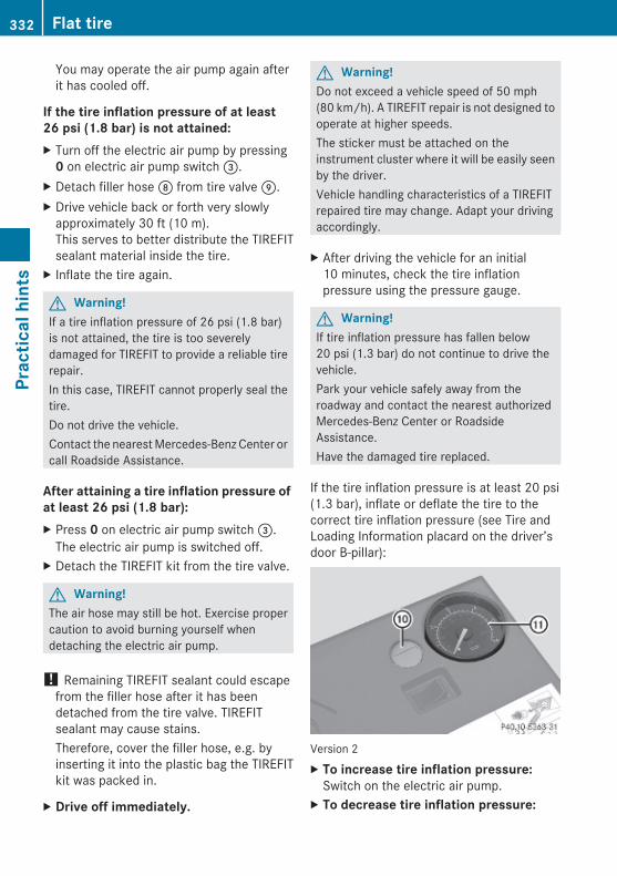
You may operate the air pump again afterit has cooled off.
If the tire inflation pressure of at least 26 psi (1.8 bar) is not attained:X Turn off the electric air pump by pressing
0 on electric air pump switch =.X Detach filler hose D from tire valve E.X Drive vehicle back or forth very slowly
approximately 30 ft (10 m).This serves to better distribute the TIREFITsealant material inside the tire.
X Inflate the tire again.
G Warning!If a tire inflation pressure of 26 psi (1.8 bar)is not attained, the tire is too severelydamaged for TIREFIT to provide a reliable tirerepair.In this case, TIREFIT cannot properly seal thetire.Do not drive the vehicle.Contact the nearest Mercedes-Benz Center orcall Roadside Assistance.
After attaining a tire inflation pressure of at least 26 psi (1.8 bar):X Press 0 on electric air pump switch =.
The electric air pump is switched off.X Detach the TIREFIT kit from the tire valve.
G Warning!The air hose may still be hot. Exercise propercaution to avoid burning yourself whendetaching the electric air pump.
! Remaining TIREFIT sealant could escapefrom the filler hose after it has beendetached from the tire valve. TIREFITsealant may cause stains.Therefore, cover the filler hose, e.g. byinserting it into the plastic bag the TIREFITkit was packed in.
X Drive off immediately.
G Warning!Do not exceed a vehicle speed of 50 mph(80 km/h). A TIREFIT repair is not designed tooperate at higher speeds.The sticker must be attached on theinstrument cluster where it will be easily seenby the driver.Vehicle handling characteristics of a TIREFITrepaired tire may change. Adapt your drivingaccordingly.
X After driving the vehicle for an initial10 minutes, check the tire inflationpressure using the pressure gauge.
G Warning!If tire inflation pressure has fallen below20 psi (1.3 bar) do not continue to drive thevehicle.Park your vehicle safely away from theroadway and contact the nearest authorizedMercedes-Benz Center or RoadsideAssistance.Have the damaged tire replaced.
If the tire inflation pressure is at least 20 psi(1.3 bar), inflate or deflate the tire to thecorrect tire inflation pressure (see Tire andLoading Information placard on the driver’sdoor B-pillar):
Version 2X To increase tire inflation pressure:
Switch on the electric air pump.X To decrease tire inflation pressure:
332 Flat tirePr
actic
al h
ints
212_AKB; 2; 41, en-USd2ureepe, Version: 2.11.8.1
2009-07-17T09:14:21+02:00 - Seite 332
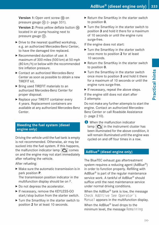
Version 1: Open vent screw F onpressure gauge G (Y page 331).Version 2: Press yellow deflate button alocated in air pump housing next topressure gauge G.
X Drive to the nearest qualified workshop,e.g. an authorized Mercedes-Benz Center,to have the damaged tire replaced.
X Recommended duration of use: Amaximum of 300 miles (500 km) at 50 mph(80 km/h) or below with the recommendedtire inflation pressure.
X Contact an authorized Mercedes-BenzCenter as soon as possible to obtain a newTIREFIT kit.
X Bring used TIREFIT materials to anauthorized Mercedes-Benz Center forproper disposal.
X Replace your TIREFIT container every4 years. Replacement containers areavailable at any authorized Mercedes-BenzCenter.
Bleeding the fuel system (diesel engine only)
Driving the vehicle until the fuel tank is emptyis not recommended. Otherwise, air may besucked into the fuel system. If this happens,the malfunction indicator lamp ; comeson and the engine may not start immediatelyafter refueling the vehicle.After refueling:X Make sure the automatic transmission is in
park position P.The transmission position indicator in themultifunction display should be on P.
X Do not depress the accelerator.X If necessary, remove the KEYLESS-GO
start/stop button from the starter switch.X Turn the SmartKey in the starter switch to
position 2 for at least 10 seconds.
X Return the SmartKey in the starter switchto position 0.
X Turn the SmartKey in the starter switch toposition 3 and hold it there for a maximumof 10 seconds or until the engine runssurge-free.
If the engine does not start:X Turn the SmartKey in the starter switch
once more to position 2 for at least10 seconds.
X Return the SmartKey in the starter switchto position 0.
X Turn the SmartKey in the starter switchonce more to position 3 and hold it therefor a maximum of 10 seconds or until theengine runs surge-free.
X If necessary, repeat the above steps.If the engine still does not start after3 attempts:Do not make any further attempts to start theengine. Contact an authorized Mercedes-Benz Center or call Roadside Assistance(Y page 210).
i When the malfunction indicatorlamp ; in the instrument cluster hasbeen illuminated for the above condition, itwill remain illuminated until the engine wascycled on and off four times in a row.
AdBlue® (diesel engine only)
The BlueTEC exhaust gas aftertreatmentsystem requires a reducing agent (AdBlue®)in order to function properly. Refilling withAdBlue® is part of the regular maintenanceservice work. A tankful of AdBlue® shouldsuffice until the next maintenance serviceunder normal driving conditions.When the AdBlue® tank is low, the messageCheck Additive See Operator’s Manual appears in the multifunction display.When the AdBlue® level drops to theminimum level, the message Remaining
AdBlue® (diesel engine only) 333
Prac
tical
hin
ts
212_AKB; 2; 41, en-USd2ureepe, Version: 2.11.8.1
2009-07-17T09:14:21+02:00 - Seite 333
Z

Starts: 20 appears in the multifunctiondisplay.
i When the message Remaining Starts: 20 appears in the multifunction display, youcan start the engine 20 more times. If youdo not add AdBlue®, the engine cannot bestarted beyond that point. Fill theAdBlue® tank with approximately 1 gal(3.79 l) AdBlue® (corresponds toapproximately 2 AdBlue® refill containers)or have the AdBlue® tank filled by anauthorized Mercedes-Benz Center.
i For refilling outside the maintenanceservice intervals, refill the AdBlue® tankwith approximately 1 gal (3.79 l) AdBlue®
(corresponds to approximately 2 AdBlue®
refill containers).
Always use the particular AdBlue® refillcontainers for refilling outside themaintenance service interval. Contact anauthorized Mercedes-Benz Center or callRoadside Assistance if necessary(Y page 210).Additional information on BlueTEC exhaustgas aftertreatment and AdBlue® is availableat any authorized Mercedes-Benz Center.
Refilling with AdBlue®
G Warning!Make sureRAdBlue® does not come into contact with
skin, eyes, or clothingRto keep AdBlue® out of the reach of children
If you and/or others have come into contactwith AdBlue®:RIf AdBlue® has gotten into contact with
eyes, flush with plenty of water immediatelyand seek medical help.RClean affected skin immediately with plenty
of water.RIf AdBlue® was swallowed, rinse mouth
immediately with plenty of water and drinkplenty of water. Consult a physician.
G Warning!When opening the filler cap of the AdBlue®
tank ammonia gas vapors may escape. RefillAdBlue® in a well ventilated area only.Ammonia gas vapors have a pungent odor andare particularly irritating for your skin,mucous membranes, and eyes. Inhalingammonia gas vapors will cause burning eyes,nose, and throat, as well as coughing andwatering eyes.
! Only use AdBlue® complying withISO 22241. Do not add additives toAdBlue® and do not dilute AdBlue® withwater. Otherwise, the BlueTEC exhaust gasaftertreatment system could be damaged.Damage caused by using additives ordiluting with water are not covered by theMercedes-Benz Limited Warranty.
! Rinse surfaces that have come intocontact with AdBlue®, or remove AdBlue®
with a moist cloth and cold waterimmediately. If AdBlue® has crystallizedalready, use cold water and a sponge.AdBlue® residues will crystallize and soilthe affected surfaces.
! AdBlue® is not a fuel additive and mustnot be added to the diesel fuel tank. IfAdBlue® reaches the diesel fuel tank, theengine could be damaged which is notcovered by the Mercedes-Benz LimitedWarranty.
334 AdBlue® (diesel engine only)Pr
actic
al h
ints
212_AKB; 2; 41, en-USd2ureepe, Version: 2.11.8.1
2009-07-17T09:14:21+02:00 - Seite 334

For more information on AdBlue®, see(Y page 364).The AdBlue® filler neck is located in the spaceunderneath the trunk floor.X Switch off the ignition.X Open the trunk (Y page 81).X Lift the trunk floor (Y page 268).
X Turn AdBlue® filler cap cover :counterclockwise and remove it.
X Turn AdBlue® filler cap ;counterclockwise and open it.Filler cap ; is tethered with a plastic strap.
X Unscrew the dust cap from AdBlue® refillcontainer =.
X Place AdBlue® refill container = on thefiller neck as illustrated and tighten itmoderately (hand-tight) by turning itclockwise.
! Make sure to tighten the AdBlue® refillcontainer only moderately, i.e. hand-tight,as you could otherwise damage it.
X Push AdBlue® refill container = down.The AdBlue® tank is filled. This may take upto 1 minute.
i When you stop pushing the AdBlue® refillcontainer down, the filling process isstopped and you can remove the refillcontainer.
X Release AdBlue® refill container =.X Turn AdBlue® refill container =
counterclockwise and remove it.X Place AdBlue® filler cap ; on filler neck
and turn it clockwise.
AdBlue® (diesel engine only) 335
Prac
tical
hin
ts
212_AKB; 2; 41, en-USd2ureepe, Version: 2.11.8.1
2009-07-17T09:14:21+02:00 - Seite 335
Z
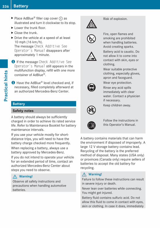
X Place AdBlue® filler cap cover : asillustrated and turn it clockwise to its stop.
X Lower the trunk floor.X Close the trunk.X Drive the vehicle at a speed of at least
10 mph (16 km/h).The message Check Additive See Operator’s Manual disappears afterapproximately 1 minute.
i If the message Check Additive See Operator’s Manual still appears in themultifunction display, refill with one morecontainer of AdBlue®.
i Have the AdBlue® level checked and, ifnecessary, filled completely afterward atan authorized Mercedes-Benz Center.
Battery
Safety notesA battery should always be sufficientlycharged in order to achieve its rated servicelife. Refer to Maintenance Booklet for batterymaintenance intervals.If you use your vehicle mostly for short-distance trips, you will need to have thebattery charge checked more frequently.When replacing a battery, always use abattery approved by Mercedes-Benz.If you do not intend to operate your vehiclefor an extended period of time, contact anauthorized Mercedes-Benz Center aboutsteps you need to observe.
G Warning!Observe all safety instructions andprecautions when handling automotivebatteries.
Risk of explosion.
Fire, open flames andsmoking are prohibitedwhen handling batteries.Avoid creating sparks.Battery acid is caustic. Donot allow it to come intocontact with skin, eyes orclothing.Wear suitable protectiveclothing, especially gloves,apron and faceguard.Wear eye protection.Rinse any acid spillsimmediately with clearwater. Contact a physicianif necessary.Keep children away.
Follow the instructions inthis Operator’s Manual.
A battery contains materials that can harmthe environment if disposed of improperly. Alarge 12 V storage battery contains lead.Recycling of the battery is the preferredmethod of disposal. Many states (USA only)or provinces (Canada only) require sellers ofbatteries to accept the old battery forrecycling.
G Warning!Failure to follow these instructions can resultin severe injury or death.Never lean over batteries while connecting.You might get injured.Battery fluid contains sulfuric acid. Do notallow this fluid to come in contact with eyes,skin or clothing. In case it does, immediately
336 BatteryPr
actic
al h
ints
212_AKB; 2; 41, en-USd2ureepe, Version: 2.11.8.1
2009-07-17T09:14:21+02:00 - Seite 336
flush affected area with water and seekmedical help if necessary.A battery will also produce hydrogen gas,which is flammable and explosive. Keepflames or sparks away from battery, avoidimproper connection of jumper cables,smoking etc.
G Warning!Do not place metal objects on the battery asthis could result in a short circuit.Use leak-proof batteries only to avoid the riskof acid burns in the event of an accident.Take care that you do not become staticallycharged, e.g. by wearing synthetic clothing orrubbing against textiles. For this reason, youalso should not pull or push the battery overcarpets or other synthetic materials.Never touch the battery first. First touch theoutside body of the vehicle in order to releaseany possible electrostatic charges.Do not rub the battery with rags or cloths. Thebattery could explode if touched due toelectrostatic charge or due to sparkformation.
! The battery is a Valve-Regulated LeadAcid (VRLA) battery, also referred to as“fleece” battery.Such batteries do not require topping-up ofthe electrolyte level. VRLA batteriestherefore do not have cell caps and thebattery cover is non-removable. Do notattempt to open the battery as otherwisethe battery will be damaged.VRLA batteries do not require topping-up ofthe electrolyte level. They cannot beopened to check the electrolyte level.However, the battery condition must bechecked periodically by performing abattery conductance test. Refer toMaintenance Booklet for battery conditiontesting intervals.
The factory-equipped battery may only bereplaced with a battery thatRhas the same security featuresRis of identical sizeRis of identical voltageRis of identical capacity
! As any other battery, the battery maydischarge if you do not operate the vehiclefor an extended period of time. Have thebattery disconnected at a qualifiedworkshop or an authorized Mercedes-BenzCenter in such a case. You may alsoconnect an accessory battery charge unitexpressly approved by Mercedes-Benz foryour vehicle model to maintain the batterycharge. Contact an authorized Mercedes-Benz Center for further information.The battery, the battery ventilation hoseand the lateral plug must always besecurely installed when the vehicle is inoperation.
! Never loosen or detach battery terminalclamps while the engine is running or theSmartKey is in the starter switch orKEYLESS-GO button is in position 1.Otherwise the alternator and otherelectronic components could be severelydamaged.Have the battery checked regularly at anauthorized Mercedes-Benz Center.Refer to Maintenance Booklet formaintenance intervals or contact anauthorized Mercedes-Benz Center forfurther information.
Charging the battery
G Warning!Never charge a battery while still installed inthe vehicle unless the accessory batterycharge unit approved by Mercedes-Benz isbeing used. Gases may escape during
Battery 337
Prac
tical
hin
ts
212_AKB; 2; 41, en-USd2ureepe, Version: 2.11.8.1
2009-07-17T09:14:21+02:00 - Seite 337
Z

charging and could cause an explosion thatmay result in personal injury, paint damage orcorrosion.An accessory battery charge unit speciallyadapted for Mercedes-Benz vehicles andtested and approved by Mercedes-Benz isavailable. It permits the charging of thebattery in its installed position. Contact anauthorized Mercedes-Benz Center forinformation and availability.Charge battery in accordance with theseparate instructions for the accessorybattery charger.
Have the battery charged at an authorizedMercedes-Benz Center. If you charge thebattery yourself, follow the operatinginstructions for your charging device.Only use a battery charge unit with amaximum charging voltage of 14.8 V.X Charge battery in accordance with the
instructions of the battery chargermanufacturer.
Jump starting
G Warning!Failure to follow these directions will causedamage to the electronic components, andcan lead to a battery explosion and severeinjury or death.Never lean over batteries while connecting orjump starting. You might get injured.Battery fluid contains sulfuric acid. Do notallow this fluid to come in contact with eyes,skin or clothing. In case it does, immediatelyflush affected area with water, and seekmedical help if necessary.A battery will also produce hydrogen gas,which is flammable and explosive. Keepflames or sparks away from battery, avoid
improper connection of jumper cables,smoking, etc.Attempting to jump start a frozen battery canresult in it exploding, causing personal injury.Read all instructions before proceeding.
! Do not tow-start the vehicle. You couldotherwise seriously damage the automatictransmission which is not covered by theMercedes-Benz Limited Warranty.
! Jump starting should only be performedusing the jump-start terminals located inthe engine compartment.Avoid repeated and lengthy startingattempts.Do not attempt to start the engine using abattery quick-charge unit.If the engine does not run after severalunsuccessful starting attempts, have itchecked at the nearest authorizedMercedes-Benz Center.Excessive unburned fuel generated byrepeated failed starting attempts maydamage the catalytic converter21 and maypresent a fire risk.Make sure the jumper cables do not haveloose or missing insulation.Make sure the cable clamps do not touchany other metal part while the other end isstill attached to a battery.
If the battery is discharged, the engine can bestarted with jumper cables and the fullycharged battery of another vehicle or anequivalent starter pack. Observe thefollowing:RAccess to the battery is not possible on all
vehicles. If you cannot access the batteryof the other vehicle, provide jump start
21 Vehicles with gasoline engine only.
338 Jump startingPr
actic
al h
ints
212_AKB; 2; 41, en-USd2ureepe, Version: 2.11.8.1
2009-07-17T09:14:21+02:00 - Seite 338
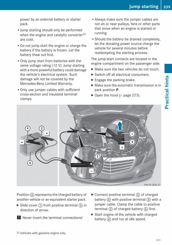
power by an external battery or starterpack.RJump starting should only be performed
when the engine and catalytic converter22
are cold.RDo not jump start the engine or charge the
battery if the battery is frozen. Let thebattery thaw out first.ROnly jump start from batteries with the
same voltage rating (12 V). Jump startingwith a more powerful battery could damagethe vehicle’s electrical system. Suchdamage will not be covered by theMercedes-Benz Limited Warranty.ROnly use jumper cables with sufficient
cross-section and insulated terminalclamps.
RAlways make sure the jumper cables arenot on or near pulleys, fans or other partsthat move when an engine is started orrunning.RShould the battery be drained completely,
let the donating power source charge thevehicle for several minutes beforereattempting the starting process.
The jump-start contacts are located in theengine compartment on the passenger side.X Make sure the two vehicles do not touch.X Switch off all electrical consumers.X Engage the parking brake.X Make sure the automatic transmission is in
park position P.X Open the hood (Y page 223).
Position B represents the charged battery ofanother vehicle or an equivalent starter pack.X Slide cover : from positive terminal = in
direction of arrow.
! Never invert the terminal connections!
X Connect positive terminal ; of chargedbattery B with positive terminal = with ajumper cable. Clamp the cable to positiveterminal ; of charged battery B first.
X Start engine of the vehicle with chargedbattery B and run at idle speed.
22 Vehicles with gasoline engine only.
Jump starting 339
Prac
tical
hin
ts
212_AKB; 2; 41, en-USd2ureepe, Version: 2.11.8.1
2009-07-17T09:14:21+02:00 - Seite 339
Z

X Connect negative terminal ? of chargedbattery B with negative terminal A witha jumper cable. Clamp the cable tonegative terminal ? of charged batteryB first.
X Start engine of the vehicle with thedischarged battery and run at idle speed.You can now turn on the electricalconsumers. Do not switch on theheadlamps under any circumstances.
X Remove the jumper cables from negativeterminals ? and A first.
X Remove the jumper cables from positiveterminals ; and =.You can now switch on the headlamps.
X Slide cover : from positive terminal =back.
X Have the battery checked at the nearestauthorized Mercedes-Benz Center.
Towing the vehicle
Safety notes
G Warning!The vehicle is braked when the HOLD functionor DISTRONIC PLUS is activated. Therefore,deactivate the HOLD function or DISTRONICPLUS if the vehicle is to be towed.
Mercedes-Benz recommends that the vehiclebe transported with all wheels off the groundusing flatbed or appropriate wheel lift/dollyequipment. This method is preferable to othertypes of towing.
! To prevent damage during transport, donot tie down vehicle by its chassis orsuspension parts.
If circumstances do not permit therecommended towing methods, the vehiclemay be towed with all wheels on the groundor front axle raised (except vehicles with4MATIC) only so far as necessary to have thevehicle moved to a safe location where the
recommended towing methods can beemployed.
! Before towing the vehicle observe thefollowing instructions:RDo not tow-start the vehicle. You could
otherwise seriously damage theautomatic transmission which is notcovered by the Mercedes-Benz LimitedWarranty.RDo not tow with sling-type equipment.
Towing with sling-type equipment overbumpy roads will damage radiator andsupports.RTowing of the vehicle should only be
done using the properly installed towingeye bolt. Never attach a tow cable, towrope or tow rod to the vehicle chassis,frame or suspension parts.
G Warning!With the engine not running, there is no powerassistance for the brake and steeringsystems. In this case, it is important to keepin mind that a considerably higher degree ofeffort is necessary to brake and steer thevehicle. Adapt your driving accordingly.
! Avoid pulling the vehicle abruptly ordiagonally, since it could result in damageto the chassis alignment.
! Do not use the towing eye bolt forrecovery, as this could damage the vehicle.If in doubt, recover the vehicle with a crane.
i If the battery is disconnected ordischargedRthe SmartKey will not turn in the starter
switchRthe automatic transmission will remain in
park position PFor more information see “Battery”(Y page 336) or “Jump starting”(Y page 338).
340 Towing the vehiclePr
actic
al h
ints
212_AKB; 2; 41, en-USd2ureepe, Version: 2.11.8.1
2009-07-17T09:14:21+02:00 - Seite 340

Installing towing eye boltDepending on whether you are towing avehicle or you are being towed, the towing eyebolt can be screwed into threaded holeswhich are located behind covers on eachbumper.The towing eye bolt is supplied with thevehicle tool kit, located underneath the trunkfloor (Y page 268).X Take the vehicle tool kit out of the trunk.
Removing cover in front bumper
X Press mark on cover : as indicated by thearrow.
X Lift cover : off to reveal the threaded holefor the towing eye bolt.
Removing cover in rear bumper
G Warning!In order to avoid possible serious burns orinjury, use extreme caution when removingthe rear cover, because the rear exhaust pipeis extremely hot.
X Press mark on cover : as indicated by thearrow.
X Lift cover : off to reveal the threaded holefor the towing eye bolt.
Fixing towing eye bolt
Example illustration front bumper
X Take the towing eye bolt and, if soequipped, the wheel wrench from thevehicle tool kit (Y page 268).
X Screw towing eye bolt ; clockwise intothreaded hole to its stop.
X Insert wheel wrench into towing eye andtighten towing eye bolt ; by turning itclockwise.
orX If your vehicle is not equipped with a wheel
wrench, use a suitable object to turn thetowing eye bolt.
Towing the vehicle 341
Prac
tical
hin
ts
212_AKB; 2; 41, en-USd2ureepe, Version: 2.11.8.1
2009-07-17T09:14:21+02:00 - Seite 341
Z
Removing towing eye boltX Loosen towing eye bolt ; by turning it
counterclockwise.X Unscrew towing eye bolt ;.X Reinstalling cover: Fit cover :
(Y page 341) and snap it into place.X Store the towing eye bolt ; and wheel
wrench back into the vehicle tool kit.
Towing with one axle raised! The vehicle may be towed only for
distances up to 30 miles (50 km) and at aspeed not to exceed 30 mph (50 km/h).
! Vehicles with 4MATIC: Do not tow withone axle raised. Doing so could damage thetransfer case, which is not covered by theMercedes-Benz Limited Warranty.All wheels must be on or off the ground.Observe instructions for towing the vehiclewith all wheels on the ground.
X Make sure the ignition is switched on.X With the vehicle at a standstill, depress the
brake pedal and keep it pressed.X Release the brake pedal.X If engaged, release the parking brake.X Switch off the automatic central locking
(Y page 144).X Switch off the ignition and leave the
SmartKey in the starter switch.X Switch on the hazard warning flasher
(Y page 101).
! Because the ESC operates automatically,the engine and ignition must be shut off(SmartKey in starter switch position 0 or1 or KEYLESS-GO start/stop button inposition 0 or 1) when the vehicle is beingtowed with one axle raised.Active braking action through the ESC mayotherwise seriously damage the brakesystem which is not covered by theMercedes-Benz Limited Warranty.
Towing with all wheels on the ground
G Warning!If circumstances require towing the vehiclewith all wheels on the ground, always tow witha tow bar if:Rthe engine will not runRthere is a malfunction in the brake systemRthere is a malfunction in the power supply
or in the vehicle’s electrical system
This is necessary to adequately control thetowed vehicle.Prior to towing the vehicle with all wheels onthe ground, make sure the SmartKey is instarter switch position 2.If the SmartKey is left in the starter switchposition 0 for an extended period of time, itcan no longer be turned in the switch. In thiscase, the steering is locked. To unlock,remove SmartKey from starter switch andreinsert.
G Warning!With the engine not running, there is no powerassistance for the brake and steeringsystems. In this case, it is important to keepin mind that a considerably higher degree ofeffort is necessary to brake and steer thevehicle. Adapt your driving accordingly.
X Make sure the ignition is switched on.X With the vehicle at a standstill, depress the
brake pedal and keep it pressed.X Shift the automatic transmission into
neutral position N.X Release the brake pedal.X If engaged, release the parking brake.X Switch on the hazard warning flasher
(Y page 101).
! The vehicle may be towed only fordistances up to 30 miles (50 km) and at aspeed not to exceed 30 mph (50 km/h).
342 Towing the vehiclePr
actic
al h
ints
212_AKB; 2; 41, en-USd2ureepe, Version: 2.11.8.1
2009-07-17T09:14:21+02:00 - Seite 342

i While being towed with the hazardwarning flasher in use, use the combinationswitch in the usual manner to signal turns.Only the selected turn signal will operate.Upon canceling the turn signal, the hazardwarning flasher will operate again.
Fuses
IntroductionThe electrical fuses in your vehicle serve toswitch off malfunctioning power circuits.If a fuse is blown, the components andsystems secured by that fuse will stopoperating.
G Warning!Only use fuses approved by Mercedes-Benzwith the specified amperage for the system inquestion and do not attempt to repair orbridge a blown fuse. Using other thanapproved fuses or using repaired or bridgedfuses may cause an overload leading to a fire,and/or cause damage to electricalcomponents and/or systems. Have the causedetermined and remedied by an authorizedMercedes-Benz Center.
A blown fuse must be replaced by anappropriate spare fuse (recognizable by itscolor or the fuse rating given on the fuse) ofthe amperage recommended in the fusechart. Any Mercedes-Benz Center will be gladto advise you on this subject.
i In case of a blown fuse contact RoadsideAssistance or an authorized Mercedes-Benz Center.
If a newly inserted fuse blows again, have thecause determined and rectified by anauthorized Mercedes-Benz Center.The fuse chart is located in the trunk with thevehicle tool kit (Y page 268). The fuse chartexplains the fuse allocation and fuseamperages.
Before replacing fusesX Engage the parking brake.X Make sure the automatic transmission is in
park position P.The transmission position indicator in themultifunction display should be on P.
X Switch off all electrical consumers.X Turn off the engine.X Remove the SmartKey from the starter
switch.X Vehicles with KEYLESS-GO: Open the
driver’s door (this puts the starter switch inposition 0, same as with the SmartKeyremoved from the starter switch). Thedriver’s door then can be closed again.
Fuse box in trunk
X Open the trunk.X Opening: Insert flat, blunt object as a lever
into the upper edge of cover : and pullcover : downward in direction of arrow.
X Closing: Install cover :.
Fuse box in engine compartmentX Open the hood.
Fuses 343
Prac
tical
hin
ts
212_AKB; 2; 41, en-USd2ureepe, Version: 2.11.8.1
2009-07-17T09:14:21+02:00 - Seite 343
Z
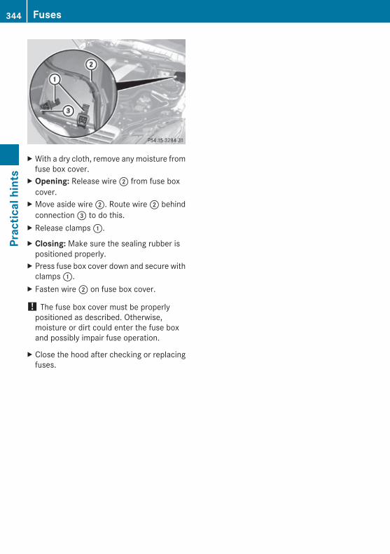
X With a dry cloth, remove any moisture fromfuse box cover.
X Opening: Release wire ; from fuse boxcover.
X Move aside wire ;. Route wire ; behindconnection = to do this.
X Release clamps :.
X Closing: Make sure the sealing rubber ispositioned properly.
X Press fuse box cover down and secure withclamps :.
X Fasten wire ; on fuse box cover.
! The fuse box cover must be properlypositioned as described. Otherwise,moisture or dirt could enter the fuse boxand possibly impair fuse operation.
X Close the hood after checking or replacingfuses.
344 FusesPr
actic
al h
ints
212_AKB; 2; 41, en-USd2ureepe, Version: 2.11.8.1
2009-07-17T09:14:21+02:00 - Seite 344

Vehicle equipment ............................ 346Parts service ..................................... 346Warranty coverage ........................... 346Identification labels .......................... 346Vehicle specification E 350(212.056) ........................................... 348Vehicle specification E 350 Blue-TEC (212.024) ................................... 348Vehicle specification E 3504MATIC (212.087) ............................. 349Vehicle specification E 550(212.072) ........................................... 350Vehicle specification E 5504MATIC (212.090) ............................. 351Vehicle specification E 63 AMG(212.077) ........................................... 352Rims and tires ................................... 353Fuels, coolants, lubricants, etc. ...... 359
345
Tech
nica
l dat
a
212_AKB; 2; 41, en-USd2ureepe, Version: 2.11.8.1
2009-07-17T09:14:21+02:00 - Seite 345
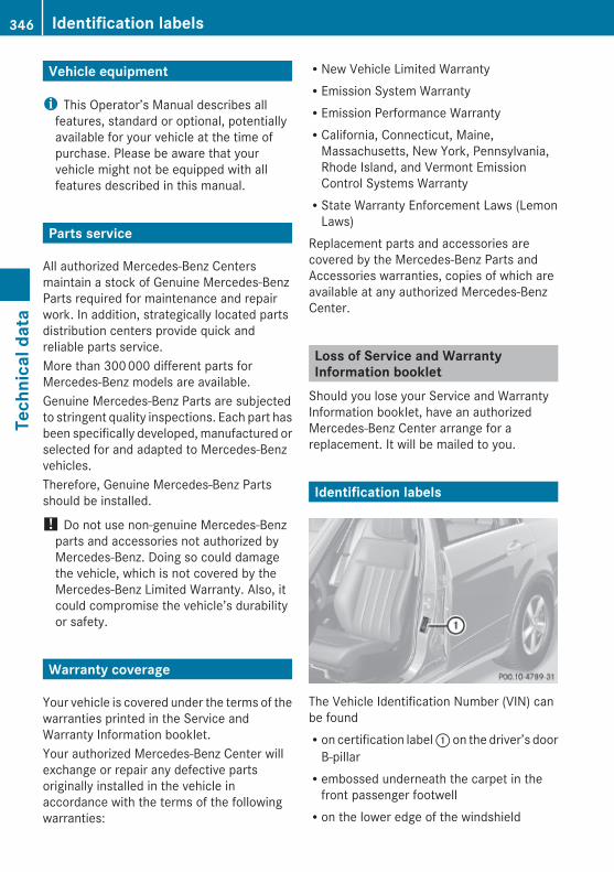
Vehicle equipment
i This Operator’s Manual describes allfeatures, standard or optional, potentiallyavailable for your vehicle at the time ofpurchase. Please be aware that yourvehicle might not be equipped with allfeatures described in this manual.
Parts service
All authorized Mercedes-Benz Centersmaintain a stock of Genuine Mercedes-BenzParts required for maintenance and repairwork. In addition, strategically located partsdistribution centers provide quick andreliable parts service.More than 300 000 different parts forMercedes-Benz models are available.Genuine Mercedes-Benz Parts are subjectedto stringent quality inspections. Each part hasbeen specifically developed, manufactured orselected for and adapted to Mercedes-Benzvehicles.Therefore, Genuine Mercedes-Benz Partsshould be installed.
! Do not use non-genuine Mercedes-Benzparts and accessories not authorized byMercedes-Benz. Doing so could damagethe vehicle, which is not covered by theMercedes-Benz Limited Warranty. Also, itcould compromise the vehicle’s durabilityor safety.
Warranty coverage
Your vehicle is covered under the terms of thewarranties printed in the Service andWarranty Information booklet.Your authorized Mercedes-Benz Center willexchange or repair any defective partsoriginally installed in the vehicle inaccordance with the terms of the followingwarranties:
RNew Vehicle Limited WarrantyREmission System WarrantyREmission Performance WarrantyRCalifornia, Connecticut, Maine,
Massachusetts, New York, Pennsylvania,Rhode Island, and Vermont EmissionControl Systems WarrantyRState Warranty Enforcement Laws (Lemon
Laws)Replacement parts and accessories arecovered by the Mercedes-Benz Parts andAccessories warranties, copies of which areavailable at any authorized Mercedes-BenzCenter.
Loss of Service and Warranty Information booklet
Should you lose your Service and WarrantyInformation booklet, have an authorizedMercedes-Benz Center arrange for areplacement. It will be mailed to you.
Identification labels
The Vehicle Identification Number (VIN) canbe foundRon certification label : on the driver’s door
B-pillarRembossed underneath the carpet in the
front passenger footwellRon the lower edge of the windshield
346 Identification labelsTe
chni
cal d
ata
212_AKB; 2; 41, en-USd2ureepe, Version: 2.11.8.1
2009-07-17T09:14:21+02:00 - Seite 346

Example certification label (U.S. vehicles); VIN= Paintwork code
Example certification label (Canada vehicles); VIN= Paintwork code
i Data shown on certification label are forillustration purposes only. These data arespecific to each vehicle and may vary fromdata shown in the illustration. Refer tocertification label on vehicle for actual dataspecific to your vehicle.
X Move the front passenger seat backwardas far as possible (Y page 88).
X Fold carpet ? backward.VIN A is now visible.
B Emission control information label,includes both federal and Californiacertification exhaust emission standards
C VIN (on lower edge of windshield)D Engine number (engraved on engine)
i When ordering parts, please specifyvehicle identification and engine number.
Identification labels 347
Tech
nica
l dat
a
212_AKB; 2; 41, en-USd2ureepe, Version: 2.11.8.1
2009-07-17T09:14:21+02:00 - Seite 347
Z

Vehicle specification E 350 (212.056)
The quoted data apply only to the standardvehicle. Contact an authorized Mercedes-Benz Center for the corresponding data of allspecial bodies and special equipment.
Engine E 350
Engine, type 272
Mode of operation 4-stroke engine,gasoline injection
No. of cylinders 6
Bore 3.66 in (92.90 mm)
Stroke 3.39 in (86.00 mm)
Total piston displacement
213.5 cu in(3 498 cm3)
Compression ratio
10.7:1
Output acc. to SAE J 134923
268 hp/6 000 rpm(200 kW/6 000 rpm)
Maximum torque acc. to SAE J 1349
258 lb-ft/2 400 - 5 000 rpm
(350 Nm/2 400 - 5 000 rpm)
Maximum engine speed
6 500 rpm
Firing order 1-4-3-6-2-5
Poly-V-belt 2 392 mm
Electrical system E 350
Alternator 14 V/180 A
Starter motor 12 V/1.4 kW
Battery 12 V/70 Ah
Spark plugs, type Bosch Y 7 MPP33
Electrical system E 350
Spark plugs, electrode gap
0.031 in (0.8 mm)
Spark plugs, tightening torque
15 - 18 lb-ft(20 - 25 Nm)
Main dimensions E 350
Overall vehicle length
191.9 in (4 874 mm)
Overall vehicle width24
81.5 in (2 071 mm)
Overall vehicle height
57.8 in (1 467 mm)
Wheelbase 113.1 in (2 874 mm)
Track, front 62.2 in (1 580 mm)
Track, rear 63.0 in (1 599 mm)
Ground clearance 4.1 in (104 mm)
Turning circle 36.9 ft (11.3 m)
Weights E 350
Roof load max. 220 lb (100 kg)
Trunk load max. 220 lb (100 kg)
Vehicle specification E 350 BlueTEC (212.024)
The quoted data apply only to the standardvehicle. Contact an authorized Mercedes-Benz Center for the corresponding data of allspecial bodies and special equipment.
23 Premium fuel required. Performance may vary with fuel octane rating.24 Exterior rear view mirrors folded out.
348 Vehicle specification E 350 BlueTEC (212.024)Te
chni
cal d
ata
212_AKB; 2; 41, en-USd2ureepe, Version: 2.11.8.1
2009-07-17T09:14:21+02:00 - Seite 348
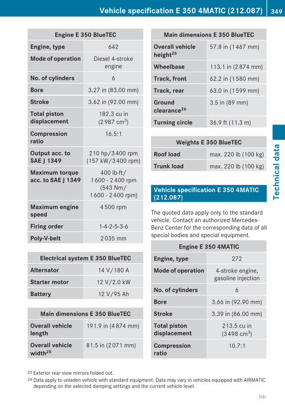
Engine E 350 BlueTEC
Engine, type 642
Mode of operation Diesel 4-strokeengine
No. of cylinders 6
Bore 3.27 in (83.00 mm)
Stroke 3.62 in (92.00 mm)
Total piston displacement
182.3 cu in(2 987 cm3)
Compression ratio
16.5:1
Output acc. to SAE J 1349
210 hp/3 400 rpm(157 kW/3 400 rpm)
Maximum torque acc. to SAE J 1349
400 lb-ft/1 600 - 2 400 rpm
(543 Nm/1 600 - 2 400 rpm)
Maximum engine speed
4 500 rpm
Firing order 1-4-2-5-3-6
Poly-V-belt 2 035 mm
Electrical system E 350 BlueTEC
Alternator 14 V/180 A
Starter motor 12 V/2.0 kW
Battery 12 V/95 Ah
Main dimensions E 350 BlueTEC
Overall vehicle length
191.9 in (4 874 mm)
Overall vehicle width25
81.5 in (2 071 mm)
Main dimensions E 350 BlueTEC
Overall vehicle height26
57.8 in (1 467 mm)
Wheelbase 113.1 in (2 874 mm)
Track, front 62.2 in (1 580 mm)
Track, rear 63.0 in (1 599 mm)
Ground clearance26
3.5 in (89 mm)
Turning circle 36.9 ft (11.3 m)
Weights E 350 BlueTEC
Roof load max. 220 lb (100 kg)
Trunk load max. 220 lb (100 kg)
Vehicle specification E 350 4MATIC (212.087)
The quoted data apply only to the standardvehicle. Contact an authorized Mercedes-Benz Center for the corresponding data of allspecial bodies and special equipment.
Engine E 350 4MATIC
Engine, type 272
Mode of operation 4-stroke engine,gasoline injection
No. of cylinders 6
Bore 3.66 in (92.90 mm)
Stroke 3.39 in (86.00 mm)
Total piston displacement
213.5 cu in(3 498 cm3)
Compression ratio
10.7:1
25 Exterior rear view mirrors folded out.26 Data apply to unladen vehicle with standard equipment. Data may vary in vehicles equipped with AIRMATIC
depending on the selected damping settings and the current vehicle level.
Vehicle specification E 350 4MATIC (212.087) 349
Tech
nica
l dat
a
212_AKB; 2; 41, en-USd2ureepe, Version: 2.11.8.1
2009-07-17T09:14:21+02:00 - Seite 349
Z

Engine E 350 4MATIC
Output acc. to SAE J 134927
268 hp/6 000 rpm(200 kW/6 000 rpm)
Maximum torque acc. to SAE J 1349
258 lb-ft/2 400 - 5 000 rpm
(350 Nm/2 400 - 5 000 rpm)
Maximum engine speed
6 500 rpm
Firing order 1-4-3-6-2-5
Poly-V-belt 2 392 mm
Electrical system E 350 4MATIC
Alternator 14 V/180 A
Starter motor 12 V/1.4 kW
Battery 12 V/70 Ah
Spark plugs, type Bosch Y 7 MPP33
Spark plugs, electrode gap
0.031 in (0.8 mm)
Spark plugs, tightening torque
15 - 18 lb-ft(20 - 25 Nm)
Main dimensions E 350 4MATIC
Overall vehicle length
191.9 in (4 874 mm)
Overall vehicle width28
81.5 in (2 071 mm)
Overall vehicle height
57.8 in (1 467 mm)
Wheelbase 113.1 in (2 874 mm)
Track, front 62.2 in (1 580 mm)
Track, rear 63.0 in (1 599 mm)
Main dimensions E 350 4MATIC
Ground clearance 4.1 in (104 mm)
Turning circle 36.9 ft (11.3 m)
Weights E 350 4MATIC
Roof load max. 220 lb (100 kg)
Trunk load max. 220 lb (100 kg)
Vehicle specification E 550 (212.072)
The quoted data apply only to the standardvehicle. Contact an authorized Mercedes-Benz Center for the corresponding data of allspecial bodies and special equipment.
Engine E 550
Engine, type 273
Mode of operation 4-stroke engine,gasoline injection
No. of cylinders 8
Bore 3.86 in (98.00 mm)
Stroke 3.56 in (90.50 mm)
Total piston displacement
333.2 cu in(5 461 cm3)
Compression ratio
10.7:1
Output acc. to SAE J 134929
382 hp/6 000 rpm(285 kW/6 000 rpm)
Maximum torque acc. to SAE J 1349
391 lb-ft/2 800 - 4 800 rpm
(530 Nm/2 800 - 4 800 rpm)
Maximum engine speed
6 500 rpm
27 Premium fuel required. Performance may vary with fuel octane rating.28 Exterior rear view mirrors folded out.29 Premium fuel required. Performance may vary with fuel octane rating.
350 Vehicle specification E 550 (212.072)Te
chni
cal d
ata
212_AKB; 2; 41, en-USd2ureepe, Version: 2.11.8.1
2009-07-17T09:14:21+02:00 - Seite 350
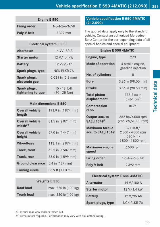
Engine E 550
Firing order 1-5-4-2-6-3-7-8
Poly-V-belt 2 392 mm
Electrical system E 550
Alternator 14 V/180 A
Starter motor 12 V/1.4 kW
Battery 12 V/95 Ah
Spark plugs, type NGK PLKR 7A
Spark plugs, electrode gap
0.031 in (0.8 mm)
Spark plugs, tightening torque
15 - 18 lb-ft(20 - 25 Nm)
Main dimensions E 550
Overall vehicle length
191.9 in (4 874 mm)
Overall vehicle width30
81.5 in (2 071 mm)
Overall vehicle height
57.0 in (1 447 mm)
Wheelbase 113.1 in (2 874 mm)
Track, front 62.5 in (1 587 mm)
Track, rear 63.0 in (1 599 mm)
Ground clearance 5.4 in (137 mm)
Turning circle 36.9 ft (11.3 m)
Weights E 550
Roof load max. 220 lb (100 kg)
Trunk load max. 220 lb (100 kg)
Vehicle specification E 550 4MATIC (212.090)
The quoted data apply only to the standardvehicle. Contact an authorized Mercedes-Benz Center for the corresponding data of allspecial bodies and special equipment.
Engine E 550 4MATIC
Engine, type 273
Mode of operation 4-stroke engine,gasoline injection
No. of cylinders 8
Bore 3.86 in (98.00 mm)
Stroke 3.56 in (90.50 mm)
Total piston displacement
333.2 cu in(5 461 cm3)
Compression ratio
10.7:1
Output acc. to SAE J 134931
382 hp/6 000 rpm(285 kW/6 000 rpm)
Maximum torque acc. to SAE J 1349
391 lb-ft/2 800 - 4 800 rpm
(530 Nm/2 800 - 4 800 rpm)
Maximum engine speed
6 500 rpm
Firing order 1-5-4-2-6-3-7-8
Poly-V-belt 2 392 mm
Electrical system E 550 4MATIC
Alternator 14 V/180 A
Starter motor 12 V/1.4 kW
Battery 12 V/95 Ah
Spark plugs, type NGK PLKR 7A
30 Exterior rear view mirrors folded out.31 Premium fuel required. Performance may vary with fuel octane rating.
Vehicle specification E 550 4MATIC (212.090) 351
Tech
nica
l dat
a
212_AKB; 2; 41, en-USd2ureepe, Version: 2.11.8.1
2009-07-17T09:14:21+02:00 - Seite 351
Z
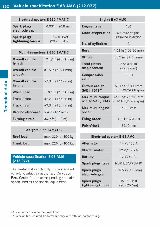
Electrical system E 550 4MATIC
Spark plugs, electrode gap
0.031 in (0.8 mm)
Spark plugs, tightening torque
15 - 18 lb-ft(20 - 25 Nm)
Main dimensions E 550 4MATIC
Overall vehicle length
191.9 in (4 874 mm)
Overall vehicle width32
81.5 in (2 071 mm)
Overall vehicle height
57.0 in (1 447 mm)
Wheelbase 113.1 in (2 874 mm)
Track, front 62.2 in (1 580 mm)
Track, rear 63.0 in (1 599 mm)
Ground clearance 5.4 in (137 mm)
Turning circle 36.9 ft (11.3 m)
Weights E 550 4MATIC
Roof load max. 220 lb (100 kg)
Trunk load max. 220 lb (100 kg)
Vehicle specification E 63 AMG (212.077)
The quoted data apply only to the standardvehicle. Contact an authorized Mercedes-Benz Center for the corresponding data of allspecial bodies and special equipment.
Engine E 63 AMG
Engine, type 156
Mode of operation 4-stroke engine,gasoline injection
No. of cylinders 8
Bore 4.02 in (102.20 mm)
Stroke 3.72 in (94.60 mm)
Total piston displacement
378.8 cu in(6 208 cm3)
Compression ratio
11.3:1
Output acc. to SAE J 134933
518 hp/6 800 rpm(386 kW/6 800 rpm)
Maximum torque acc. to SAE J 1349
465 lb-ft/5 200 rpm(630 Nm/5 200 rpm)
Maximum engine speed
7 200 rpm
Firing order 1-5-4-2-6-3-7-8
Poly-V-belt 2 360 mm
Electrical system E 63 AMG
Alternator 14 V/180 A
Starter motor 12 V/1.7 kW
Battery 12 V/80 Ah
Spark plugs, type NGK ILZKAR 7A10
Spark plugs, electrode gap
0.039 in (1.0 mm)
Spark plugs, tightening torque
15 - 18 lb-ft(20 - 25 Nm)
32 Exterior rear view mirrors folded out.33 Premium fuel required. Performance may vary with fuel octane rating.
352 Vehicle specification E 63 AMG (212.077)Te
chni
cal d
ata
212_AKB; 2; 41, en-USd2ureepe, Version: 2.11.8.1
2009-07-17T09:14:21+02:00 - Seite 352

Main dimensions E 63 AMG
Overall vehicle length
192.6 in (4 891 mm)
Overall vehicle width34
81.5 in (2 071 mm)
Overall vehicle height
56.8 in (1 442 mm)
Wheelbase 113.1 in (2 874 mm)
Track, front 64.0 in (1 625 mm)
Track, rear 62.8 in (1 594 mm)
Ground clearance 4.5 in (114 mm)
Turning circle 37.1 ft (11.30 m)
E 63 AMG
Roof load max. 220 lb (100 kg)
Trunk load max. 220 lb (100 kg)
Rims and tires
Notes! Only use tires which have been tested and
approved by Mercedes-Benz. Tiresapproved by Mercedes-Benz are developedto provide best possible performance inconjunction with the driving safety systemson your vehicle such as the ABS or the ESC.Tires specially developed for your vehicleand tested and approved by Mercedes-Benz can be identified by finding thefollowing on the tire’s sidewall:RMO = Mercedes-Benz Original
equipment tiresRMO1 = Mercedes-Benz Original
equipment tires (applicable to selectedtire sizes only)RMOE = Mercedes-Benz Original Extended
(tires with limited run-flatcharacteristics) original equipment tires
Using tires other than those approved byMercedes-Benz may result in damage thatis not covered by the Mercedes-BenzLimited Warranty.
For information on driving with MOExtendedtires, see the “Practical hints” section(Y page 329).
i USA only: Vehicles with MOExtendedsystem are not factory-equipped with aTIREFIT kit. When retrofitting with tires thatdo not have run-flat characteristics, youshould also equip your vehicle with aTIREFIT kit. TIREFIT kits are available at anyauthorized Mercedes-Benz Center.
! Using tires other than those approved byMercedes-Benz can have detrimentaleffects, such asRpoor handling characteristicsRincreased noiseRincreased fuel consumption
34 Exterior rear view mirrors folded out.
Rims and tires 353
Tech
nica
l dat
a
212_AKB; 2; 41, en-USd2ureepe, Version: 2.11.8.1
2009-07-17T09:14:21+02:00 - Seite 353
Z

Moreover, tires and rims not approved byMercedes-Benz may, under load, exhibitdimensional variations and different tiredeformation characteristics that couldcause them to come into contact with thevehicle body or axle parts. Damage to thetires or the vehicle may be the result.
i Further information on tires and rims isavailable at any authorized Mercedes-BenzCenter. The Tire and Loading Informationplacard with the recommended tireinflation pressures for cold tires is locatedon the driver’s door B-pillar. Supplementaltire inflation pressure information fordriving at high speeds or for vehicle loadsless than the maximum loaded vehiclecondition can be found on the tire inflationpressure label. The tire inflation pressurelabel is located on the inside of the fuel fillerflap. The tire inflation pressure should bechecked regularly and should only beadjusted on cold tires. Follow tiremanufacturer’s maintenancerecommendation included with the vehicle.
For information on recommended tireinflation pressure and supplemental tire
inflation pressure information for specialdriving situations, see (Y page 229).
i Please keep in mind that the vehicle mustbe equippedRwith wheels of identical dimensions on
each axle (left and right)Rwith tires of identical characteristics all
around, i.e. summer tires, winter tires,all-season tires, or MOExtended tires etc.
i The following pages also list the approvedrim and tire sizes for equipping your vehiclewith winter tires. Winter tires are notavailable as standard or optional factoryequipment, but can be purchased from anauthorized Mercedes-Benz Center.Equipping your vehicle with winter tiresapproved for your vehicle model mayrequire the purchase of rims of therecommended size for use with thesewinter tires. This depends on vehicle modeland the standard or optional factory-equipped wheel rim/tire configuration onyour vehicle. For more information contactan authorized Mercedes-Benz Center.
354 Rims and tiresTe
chni
cal d
ata
212_AKB; 2; 41, en-USd2ureepe, Version: 2.11.8.1
2009-07-17T09:14:21+02:00 - Seite 354

Same size tires
E 350 Luxury BlueTEC35 E 350 BlueTEC36
17" wheels
Rims (light alloy)Wheel offset
8.0 J x 17 H21.89 in (48 mm)
8.0 J x 17 H21.89 in (48 mm)
All-season tires37 245/45 R17 95H M+SMOExtended38
245/45 R17 99H XL(Extra Load) M+S
Winter tires37,39 245/45 R17 99V XL(Extra Load) M+SiMOExtended38
245/45 R17 99H XL(Extra Load) M+Si
E 350 Sport BlueTEC35 E 350 BlueTEC36
17" wheels
Rims (light alloy)Wheel offset
8.5 J x 17 H21.89 in (48 mm)
8.5 J x 17 H21.89 in (48 mm)
All-season tires37 245/45 R17 95H M+SMOExtended38
245/45 R17 99H XL(Extra Load) M+S
Winter tires37,39 245/45 R17 99V XL(Extra Load) M+SiMOExtended38
245/45 R17 99H XL(Extra Load) M+Si
E 350 Luxury35
E 550 Luxury35
17" wheels
Rims (light alloy)Wheel offset
8.0 J x 17 H21.89 in (48 mm)
All-season tires37 245/45 R17 99H XL (Extra Load) M+S
Winter tires37,39 245/45 R17 99H XL (Extra Load) M+Si
35 USA only.36 Canada only.37 Radial-ply tires.38 Must be used in conjunction with tire pressure loss warning system or Advanced Tire Pressure Monitoring
System only.39 Not available as factory equipment.
Rims and tires 355
Tech
nica
l dat
a
212_AKB; 2; 41, en-USd2ureepe, Version: 2.11.8.1
2009-07-17T09:14:21+02:00 - Seite 355
Z
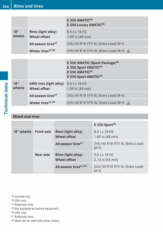
E 350 4MATIC36
E 350 Luxury 4MATIC35
18" wheels
Rims (light alloy)Wheel offset
8.5 J x 18 H21.89 in (48 mm)
All-season tires37 245/40 R18 97V XL (Extra Load) M+S
Winter tires37,39 245/40 R18 97H XL (Extra Load) M+Si
E 350 4MATIC (Sport Package)36
E 350 Sport 4MATIC35
E 550 4MATIC36
E 550 Sport 4MATIC35
18" wheels
AMG rims (light alloy)Wheel offset
8.5 J x 18 H21.89 in (48 mm)
All-season tires37 245/40 R18 97V XL (Extra Load) M+S
Winter tires37,39 245/40 R18 97H XL (Extra Load) M+Si
Mixed size tires
E 350 Sport40
18" wheels Front axle Rims (light alloy)Wheel offset
8.5 J x 18 H21.89 in (48 mm)
All-season tires41 245/40 R18 97V XL (Extra Load)M+S
Rear axle Rims (light alloy)Wheel offset
9.0 J x 18 H22.13 in (54 mm)
All-season tires41,42 265/35 R18 97V XL (Extra Load)M+S
36 Canada only.35 USA only.37 Radial-ply tires.39 Not available as factory equipment.40 USA only.41 Radial-ply tires.42 Must not be used with snow chains.
356 Rims and tiresTe
chni
cal d
ata
212_AKB; 2; 41, en-USd2ureepe, Version: 2.11.8.1
2009-07-17T09:14:21+02:00 - Seite 356
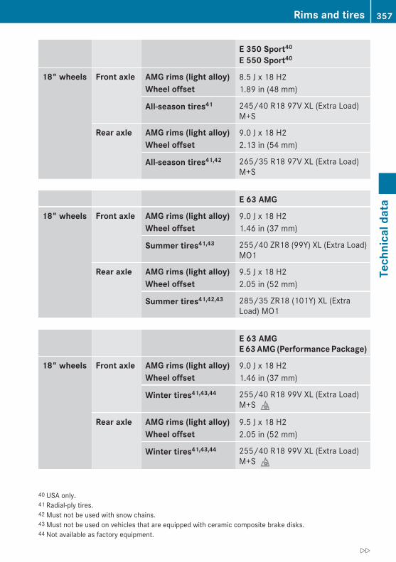
E 350 Sport40
E 550 Sport40
18" wheels Front axle AMG rims (light alloy)Wheel offset
8.5 J x 18 H21.89 in (48 mm)
All-season tires41 245/40 R18 97V XL (Extra Load)M+S
Rear axle AMG rims (light alloy)Wheel offset
9.0 J x 18 H22.13 in (54 mm)
All-season tires41,42 265/35 R18 97V XL (Extra Load)M+S
E 63 AMG
18" wheels Front axle AMG rims (light alloy)Wheel offset
9.0 J x 18 H21.46 in (37 mm)
Summer tires41,43 255/40 ZR18 (99Y) XL (Extra Load)MO1
Rear axle AMG rims (light alloy)Wheel offset
9.5 J x 18 H22.05 in (52 mm)
Summer tires41,42,43 285/35 ZR18 (101Y) XL (ExtraLoad) MO1
E 63 AMGE 63 AMG (Performance Package)
18" wheels Front axle AMG rims (light alloy)Wheel offset
9.0 J x 18 H21.46 in (37 mm)
Winter tires41,43,44 255/40 R18 99V XL (Extra Load)M+Si
Rear axle AMG rims (light alloy)Wheel offset
9.5 J x 18 H22.05 in (52 mm)
Winter tires41,43,44 255/40 R18 99V XL (Extra Load)M+Si
40 USA only.41 Radial-ply tires.42 Must not be used with snow chains.43 Must not be used on vehicles that are equipped with ceramic composite brake disks.44 Not available as factory equipment.
Rims and tires 357
Tech
nica
l dat
a
212_AKB; 2; 41, en-USd2ureepe, Version: 2.11.8.1
2009-07-17T09:14:21+02:00 - Seite 357
Z
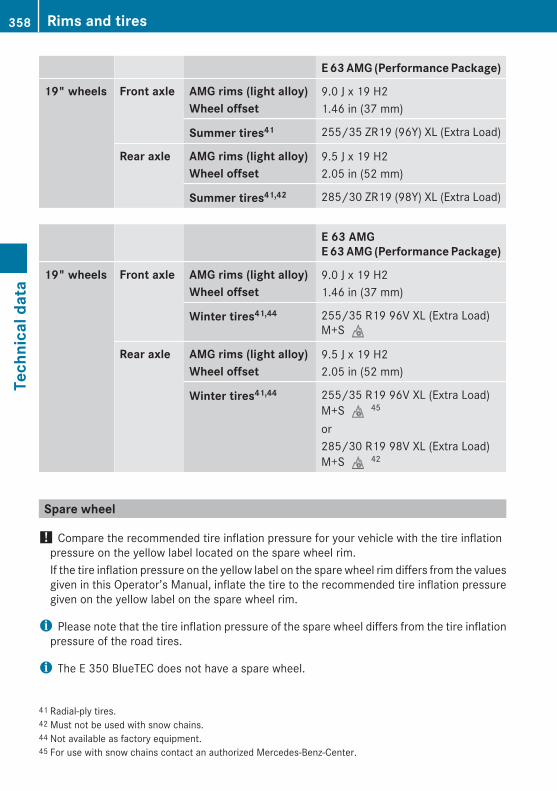
E 63 AMG (Performance Package)
19" wheels Front axle AMG rims (light alloy)Wheel offset
9.0 J x 19 H21.46 in (37 mm)
Summer tires41 255/35 ZR19 (96Y) XL (Extra Load)
Rear axle AMG rims (light alloy)Wheel offset
9.5 J x 19 H22.05 in (52 mm)
Summer tires41,42 285/30 ZR19 (98Y) XL (Extra Load)
E 63 AMGE 63 AMG (Performance Package)
19" wheels Front axle AMG rims (light alloy)Wheel offset
9.0 J x 19 H21.46 in (37 mm)
Winter tires41,44 255/35 R19 96V XL (Extra Load)M+Si
Rear axle AMG rims (light alloy)Wheel offset
9.5 J x 19 H22.05 in (52 mm)
Winter tires41,44 255/35 R19 96V XL (Extra Load)M+Si45
or285/30 R19 98V XL (Extra Load)M+Si42
Spare wheel
! Compare the recommended tire inflation pressure for your vehicle with the tire inflationpressure on the yellow label located on the spare wheel rim.If the tire inflation pressure on the yellow label on the spare wheel rim differs from the valuesgiven in this Operator’s Manual, inflate the tire to the recommended tire inflation pressuregiven on the yellow label on the spare wheel rim.
i Please note that the tire inflation pressure of the spare wheel differs from the tire inflationpressure of the road tires.
i The E 350 BlueTEC does not have a spare wheel.
41 Radial-ply tires.42 Must not be used with snow chains.44 Not available as factory equipment.45 For use with snow chains contact an authorized Mercedes-Benz-Center.
358 Rims and tiresTe
chni
cal d
ata
212_AKB; 2; 41, en-USd2ureepe, Version: 2.11.8.1
2009-07-17T09:14:21+02:00 - Seite 358
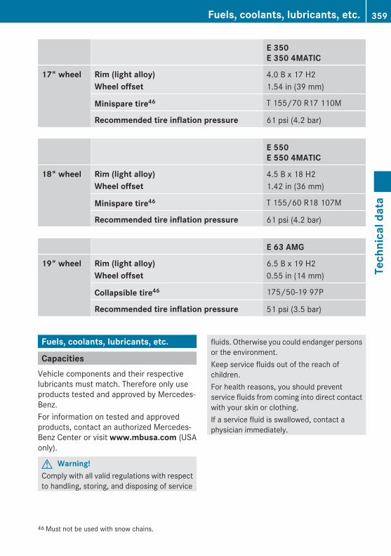
E 350E 350 4MATIC
17" wheel Rim (light alloy)Wheel offset
4.0 B x 17 H21.54 in (39 mm)
Minispare tire46 T 155/70 R17 110M
Recommended tire inflation pressure 61 psi (4.2 bar)
E 550E 550 4MATIC
18" wheel Rim (light alloy)Wheel offset
4.5 B x 18 H21.42 in (36 mm)
Minispare tire46 T 155/60 R18 107M
Recommended tire inflation pressure 61 psi (4.2 bar)
E 63 AMG
19" wheel Rim (light alloy)Wheel offset
6.5 B x 19 H20.55 in (14 mm)
Collapsible tire46 175/50-19 97P
Recommended tire inflation pressure 51 psi (3.5 bar)
Fuels, coolants, lubricants, etc.
CapacitiesVehicle components and their respectivelubricants must match. Therefore only useproducts tested and approved by Mercedes-Benz.For information on tested and approvedproducts, contact an authorized Mercedes-Benz Center or visit www.mbusa.com (USAonly).
G Warning!Comply with all valid regulations with respectto handling, storing, and disposing of service
fluids. Otherwise you could endanger personsor the environment.Keep service fluids out of the reach ofchildren.For health reasons, you should preventservice fluids from coming into direct contactwith your skin or clothing.If a service fluid is swallowed, contact aphysician immediately.
46 Must not be used with snow chains.
Fuels, coolants, lubricants, etc. 359
Tech
nica
l dat
a
212_AKB; 2; 41, en-USd2ureepe, Version: 2.11.8.1
2009-07-17T09:14:21+02:00 - Seite 359
Z

Model Capacity Fuels, coolants, lubricants, etc.
Engine with oil filter
E 350E 350 BlueTECE 350 4MATIC
8.5 US qt (8.0 l) Approved engineoils
E 550E 550 4MATIC
9.0 US qt (8.5 l)
E 63 AMG47 9.3 US qt (8.8 l)
Automatic transmission
E 350E 350 BlueTECE 550
9.5 US qt (9.0 l) MB AutomaticTransmission Fluid
E 350 4MATICE 550 4MATIC
10.5 US qt (9.9 l)
E 63 AMG 48 9.3 US qt (8.8 l)
Front axle E 350 4MATICE 550 4MATIC
0.63 US qt (0.6 l) Hypoid gear oil
Rear axle E 350 1.2 US qt (1.1 l) Hypoid gear oil
E 350 BlueTECE 550
1.3 US qt (1.2 l)
E 350 4MATICE 550 4MATIC
1.1 US qt (1.0 l)
E 63 AMG 1.3 US qt (1.2 l) Fuchs TitanEG 5010 D
Castrol SAF-XJ49
Transfer case E 350 4MATICE 550 4MATIC
0.74 US qt (0.7 l) MB AutomaticTransmission Fluid
Power steering All models,except E 63 AMG
approx. 0.95 US qt (0.9 l) MB Power SteeringFluid or approvedDexron III ATF
E 63 AMG 1.3 US qt (1.2 l) Chevron TexacoCHF 9109
47 Engine with oil cooler.48 Automatic transmission with oil cooler.49 AMG vehicles with differential lock.
360 Fuels, coolants, lubricants, etc.Te
chni
cal d
ata
212_AKB; 2; 41, en-USd2ureepe, Version: 2.11.8.1
2009-07-17T09:14:21+02:00 - Seite 360
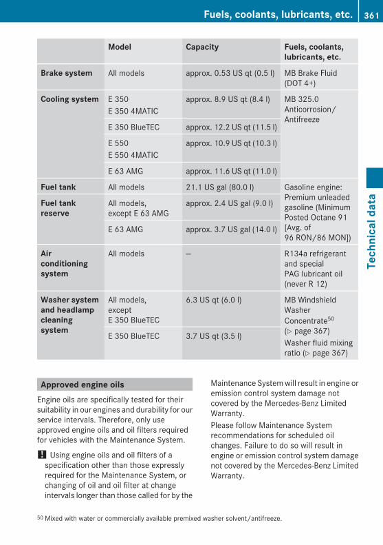
Model Capacity Fuels, coolants, lubricants, etc.
Brake system All models approx. 0.53 US qt (0.5 l) MB Brake Fluid(DOT 4+)
Cooling system E 350E 350 4MATIC
approx. 8.9 US qt (8.4 l) MB 325.0Anticorrosion/Antifreeze
E 350 BlueTEC approx. 12.2 US qt (11.5 l)
E 550E 550 4MATIC
approx. 10.9 US qt (10.3 l)
E 63 AMG approx. 11.6 US qt (11.0 l)
Fuel tank All models 21.1 US gal (80.0 l) Gasoline engine:Premium unleadedgasoline (MinimumPosted Octane 91[Avg. of96 RON/86 MON])
Fuel tank reserve
All models,except E 63 AMG
approx. 2.4 US gal (9.0 l)
E 63 AMG approx. 3.7 US gal (14.0 l)
Air conditioning system
All models — R134a refrigerantand specialPAG lubricant oil(never R 12)
Washer system and headlamp cleaning system
All models,exceptE 350 BlueTEC
6.3 US qt (6.0 l) MB WindshieldWasherConcentrate50
(Y page 367)Washer fluid mixingratio (Y page 367)
E 350 BlueTEC 3.7 US qt (3.5 l)
Approved engine oilsEngine oils are specifically tested for theirsuitability in our engines and durability for ourservice intervals. Therefore, only useapproved engine oils and oil filters requiredfor vehicles with the Maintenance System.
! Using engine oils and oil filters of aspecification other than those expresslyrequired for the Maintenance System, orchanging of oil and oil filter at changeintervals longer than those called for by the
Maintenance System will result in engine oremission control system damage notcovered by the Mercedes-Benz LimitedWarranty.Please follow Maintenance Systemrecommendations for scheduled oilchanges. Failure to do so will result inengine or emission control system damagenot covered by the Mercedes-Benz LimitedWarranty.
50 Mixed with water or commercially available premixed washer solvent/antifreeze.
Fuels, coolants, lubricants, etc. 361
Tech
nica
l dat
a
212_AKB; 2; 41, en-USd2ureepe, Version: 2.11.8.1
2009-07-17T09:14:21+02:00 - Seite 361
Z

Use the table below to determine theMB sheet number.
Model Engine,type
MB sheetnumber
E 350E 350 4MATIC
272 229.5
E 350 BlueTEC 642 229.51
E 550E 550 4MATIC
273 229.5
E 63 AMG 156 229.551
i MB sheet numbers are printed on theoutside of oil containers.
Viscosity grades for engine oilsUsing the chart below, select oil viscosityaccording to the lowest air temperatureexpected before the next oil change.
Engine oil additives! Do not blend oil additives with engine oil.
They may damage the engine. Damage ormalfunctions resulting from blending oiladditives are not covered by the Mercedes-Benz Limited Warranty.
Air conditioning refrigerantR134a (HFC) refrigerant and special PAGlubricating oil are used in the air conditioningsystem.
! Never use R 12 (CFC) or mineral-basedlubricating oil. Otherwise damage to thesystem will occur.
Brake fluid
G Warning!During vehicle operation, the boiling point ofthe brake fluid is continuously reducedthrough the absorption of moisture from theatmosphere.Under extremely strenuous operatingconditions, this moisture content can lead tothe formation of bubbles in the system, thusreducing the system’s efficiency.Therefore, the brake fluid must be replacedregularly. Refer to your vehicle’s MaintenanceBooklet for replacement interval.
Only brake fluid approved by Mercedes-Benzis recommended. Any authorized Mercedes-Benz Center will provide you with additionalinformation.
Premium unleaded gasoline
G Warning!Gasoline is highly flammable and poisonous.It burns violently and can cause seriouspersonal injury.Never allow sparks, flames or smokingmaterials near gasoline!Turn off the engine before refueling.Whenever you are around gasoline, avoidinhaling fumes and any skin or clothingcontact. Extinguish all smoking materials.
51 Restriction: Only SAE 0W-40/SAE 5W-40 engine oils may be used.
362 Fuels, coolants, lubricants, etc.Te
chni
cal d
ata
212_AKB; 2; 41, en-USd2ureepe, Version: 2.11.8.1
2009-07-17T09:14:21+02:00 - Seite 362
Direct skin contact with fuels and theinhalation of fuel vapors are damaging yourhealth.
! To maintain the engine’s durability andperformance, premium unleaded gasolinemust be used.If premium unleaded gasoline is notavailable and low octane gasoline is used,follow these precautions:RHave the fuel tank only partially filled
with unleaded regular gasoline and fill upwith premium unleaded gasoline as soonas possible.RAvoid full throttle driving and abrupt
acceleration.RDo not exceed an engine speed of
3 000 rpm if the vehicle is loaded with alight load such as two persons and noluggage.RDo not exceed 2/3 of maximum
accelerator pedal position if the vehicleis fully loaded or operating inmountainous terrain.
Fuel requirementsOnly use premium unleaded gasoline. Theoctane number (posted at the pump) must be91 min. It is an average of both the ResearchOctane Number (RON) and the Motor OctaneNumber (MON): (RON+MON)/2. This is alsoknown as the ANTI-KNOCK INDEX.Reformulated gasolines (RFG) and/orunleaded gasoline containing oxygenatessuch as ethanol, TAME, ETBE, IPA, IBA, andTBA can be used provided the ratio of any oneof these oxygenates to gasoline does notexceed 10%; MTBE must not exceed 15%.The ratio of methanol to gasoline must notexceed 3% plus additional cosolvents.Using mixtures of ethanol and methanol is notallowed. Gasohol, which contains 10%
ethanol and 90% unleaded gasoline, can beused.These blends must also meet all other fuelrequirements, such as resistance to sparkknock, boiling range, vapor pressure, etc.
Diesel engine Only use commercially available vehicularULTRA-LOW SULFUR HIGHWAY DIESEL FUEL(ULSD, 15 ppm SULFUR MAXIMUM) thatmeets the ASTM D975 standard. Failure touse ULTRA-LOW SULFUR HIGHWAY DIESELFUEL (ULSD) can severely damage thevehicle’s exhaust after-treatment device.To prevent malfunctions, diesel fuel withimproved cold flow characteristics is offeredin the winter months. Check with your fuelretailer.
! Do not fill the tank with gasoline. Do notblend diesel fuel with gasoline or kerosene.The fuel system and engine will otherwisebe damaged, which is not covered by theMercedes-Benz Limited Warranty.
For further information on diesel fuel pumplabeling, contact an authorized Mercedes-Benz Center or visit www.mbusa.com (USAonly).
Biodiesel (FAME = Fatty Acid Methyl Ester) containing fuelsMercedes-Benz USA approves the use of B5(standard ULSD which may contain amaximum of 5% biodiesel) in all Common-railinjection (CDI) and BlueTEC diesel engines.Diesel fuels containing a higher percentage ofbiodiesel, e.g. B20, as well as straightbiodiesel may cause severe damage to yourengine/fuel system and are not approved.Please ask your service station personnel forfurther information. If the B5 biodiesel blendis not sufficiently labeled to clearly indicatethat it meets the ULSD standard, please donot use it.The Mercedes-Benz Limited Warranty doesnot cover damages caused by the use of fuels
Fuels, coolants, lubricants, etc. 363
Tech
nica
l dat
a
212_AKB; 2; 41, en-USd2ureepe, Version: 2.11.8.1
2009-07-17T09:14:21+02:00 - Seite 363
Z
not meeting Mercedes-Benz approved fuelstandards.
Gasoline additivesA major concern among enginemanufacturers is carbon build-up caused bygasoline. Mercedes-Benz recommends onlythe use of quality gasoline containingadditives that prevent the build-up of carbondeposits.After an extended period of using fuelswithout such additives carbon deposits canbuild up, especially on the intake valves andin the combustion area, leading to engineperformance problems such as:RWarm-up hesitationRUnstable idleRKnocking/pingingRMisfireRPower lossIn areas where carbon deposits may beencountered due to lack of availability ofgasoline which contains these additives, theuse of Mercedes-Benz approved additives isrecommended.Contact an authorized Mercedes-Benz Centeror visit www.mbusa.com (USA only) for alisting of approved products. Followdirections on the product label.Do not blend other fuel additives with fuel.This only results in unnecessary cost and maybe harmful to the engine operation.
! Damage or malfunction resulting frompoor fuel quality or from blending additionalfuel additives other than those tested andapproved by us for use on Mercedes-Benzvehicles are not covered by the Mercedes-Benz Limited Warranty or by any pre-ownedor Extended Limited Warranties.
AdBlue®
AdBlue® is a non-flammable, non-toxic,colorless and odorless, water-soluble liquid.
! Only use AdBlue® complying withISO 22241. Do not blend with additives.
! Rinse surfaces that have come intocontact with AdBlue®, or remove AdBlue®
with a moist cloth and cold waterimmediately. If AdBlue® has crystallizedalready, use cold water and a sponge.AdBlue® residues will crystallize and soilthe affected surfaces.
High ambient temperaturesIf AdBlue® in the reservoir heats up to above122‡ (50†) for a long period of time, forexample due to direct sunlight, ammonia gasvapors may escape when opening theAdBlue® tank.
G Warning!When opening the filler cap of the AdBlue®
tank ammonia gas vapors may escape. RefillAdBlue® in a well ventilated area only.Ammonia gas vapors have a pungent odor andare particularly irritating for your skin,mucous membranes, and eyes. Inhalingammonia gas vapors will cause burning eyes,nose, and throat, as well as coughing andwatering eyes.
Low ambient temperaturesAdBlue® freezes at a temperature ofapproximately 12‡ (-11†). Your vehicle isfactory equipped with an AdBlue® preheatingsystem. The vehicle can thus be operated attemperatures below 12‡ (-11†).
Special additives
! Only use AdBlue® complying withISO 22241. Do not add additives toAdBlue® and do not dilute AdBlue® with
364 Fuels, coolants, lubricants, etc.Te
chni
cal d
ata
212_AKB; 2; 41, en-USd2ureepe, Version: 2.11.8.1
2009-07-17T09:14:21+02:00 - Seite 364

water. Otherwise, the BlueTEC exhaust gasaftertreatment system could be damaged.Damage caused by using additives ordiluting with water are not covered by theMercedes-Benz Limited Warranty.
PurityThe purity of AdBlue® is of particularimportance for avoiding malfunctions in theexhaust gas aftertreatment.If AdBlue® is pumped out of the tank, e.g.during repair work, the same liquid must notbe used to refill the tank as its purity is nolonger guaranteed.
! Impurities caused for example by otherservice products, cleaning agents, and dustresult in increased emissions,malfunctions, catalyst damage, or enginedamage.
CoolantsThe engine coolant is a mixture of water andanticorrosion/antifreeze, which provides:RCorrosion protectionRFreeze protectionRBoiling protection (by increasing the boiling
point)The cooling system was filled at the factorywith a coolant providing freeze protection toapproximately -35‡ (-37†) and corrosionprotection.
! Add premixed coolant solution only.Adding water and MB 325.0 Anticorrosion/Antifreeze separately from each other,could cause engine damage not covered bythe Mercedes-Benz Limited Warranty.
If the antifreeze mixture is effective to -35‡(-37†), the boiling point of the coolant in thepressurized cooling system is reached atapproximately 266‡ (130†).The coolant solution must be used year roundto provide the necessary corrosion protection
and increase boil-over protection. Refer tothe Maintenance Booklet for replacementinterval.Coolant system design and coolant useddetermine the replacement interval. Thereplacement interval published in theMaintenance Booklet is only applicable ifMB 325.0 Anticorrosion/Antifreeze solutionor other Mercedes-Benz approved productsof equal specification are used to renew thecoolant concentration or bring it back up tothe proper level.For information on other Mercedes-Benzapproved products of equal specification,contact an authorized Mercedes-Benz Centeror visit www.mbusa.com (USA only).To provide important corrosion protection,the solution must be at least 50%anticorrosion/antifreeze (equivalent tofreeze protection to approximately -35‡[-37†]).If you use a solution that is more than 55%anticorrosion/antifreeze (freeze protectionto approximately -49‡ [-45†]), the enginetemperature will increase due to the lowerheat transfer capability of the solution.Therefore, do not use more than this amountof anticorrosion/antifreeze.If the coolant level is low, water and MB 325.0Anticorrosion/Antifreeze should be used tobring it up to the proper level (have coolingsystem checked for signs of leakage). Pleasemake sure the mixture is in accordance withlabel instructions.The water in the cooling system must meetminimum requirements, which are usuallysatisfied by normal drinking water.If you are not sure about the water quality,contact an authorized Mercedes-BenzCenter.
Anticorrosion/antifreeze Your vehicle contains a number of aluminumparts. The use of aluminum components inmotor vehicle engines necessitates thatanticorrosion/antifreeze coolant used in
Fuels, coolants, lubricants, etc. 365
Tech
nica
l dat
a
212_AKB; 2; 41, en-USd2ureepe, Version: 2.11.8.1
2009-07-17T09:14:21+02:00 - Seite 365
Z

such engines be specifically formulated toprotect the aluminum parts. Failure to usesuch anticorrosion/antifreeze coolant willresult in a significantly shortened service life.Therefore, the following product is stronglyrecommended for use in your vehicle:MB 325.0 Anticorrosion/Antifreeze agent.
Before the start of the winter season (or oncea year in hot southern regions), you shouldhave the anticorrosion/antifreezeconcentration checked.The coolant is also regularly checked eachtime you bring your vehicle to an authorizedMercedes-Benz Center for service.
Model Approximate freeze protection
-35‡ (-37†) -49‡ (-45†)
Cooling system E 350E 350 4MATIC
4.4 US qt (4.2 l) 4.9 US qt (4.6 l)
E 350 BlueTEC 6.1 US qt (5.8 l) 6.7 US qt (6.3 l)
E 550E 550 4MATIC
5.5 US qt (5.2 l) 6.0 US qt (5.7 l)
E 63 AMG 5.8 US qt (5.5 l) 6.3 US qt (6.0 l)
366 Fuels, coolants, lubricants, etc.Te
chni
cal d
ata
212_AKB; 2; 41, en-USd2ureepe, Version: 2.11.8.1
2009-07-17T09:14:21+02:00 - Seite 366
Washer system and headlamp cleaning system
G Warning!Washer solvent/antifreeze is highlyflammable. Do not spill washer solvent/antifreeze on hot engine parts, because it mayignite and burn. You could be seriouslyburned.
X Use MB Windshield Washer Concentrate“MB SummerFit”.
X Mix with water for temperatures abovefreezing point.
X Mix with commercially available premixedwasher solvent/antifreeze fortemperatures below freezing point.
Washer fluid mixing ratio For temperatures above the freezing point:1 part “MB SummerFit” to 100 parts water(1.34 fl oz [40 ml] “MB SummerFit” to 1 gal[4.0 l] water)For temperatures below freezing point:1 part “MB SummerFit” to 100 parts solvent(1.34 fl oz [40 ml] “MB SummerFit” to 1 gal[4.0 l] solvent)
Fuels, coolants, lubricants, etc. 367
Tech
nica
l dat
a
212_AKB; 2; 41, en-USd2ureepe, Version: 2.11.8.1
2009-07-17T09:14:21+02:00 - Seite 367
Z

368
212_AKB; 2; 41, en-USd2ureepe, Version: 2.11.8.1
2009-07-17T09:14:21+02:00 - Seite 368
Service and LiteratureYour authorized Mercedes-Benz Center hastrained technicians and Genuine Mercedes-Benz Parts to service your vehicle properly.For expert advice and quality service, contactan authorized Mercedes-Benz Center.If you are interested in obtaining serviceliterature for your vehicle, please contact anauthorized Mercedes-Benz Center.We consider this the best way for you toobtain accurate information for your vehicle.For further information you can find us on theMercedes-Benz web site www.mbusa.com(USA only) or www.mercedes-benz.ca(Canada only).
G Warning!To help avoid personal injury, be extremelycareful when performing any service work orrepairs. Improper or incomplete service or theuse of incorrect or inappropriate parts ormaterials may damage the vehicle or itsequipment, which may in turn result inpersonal injury.If you have any questions about carrying outany type of service, turn to the advice of anauthorized Mercedes-Benz Center.
We reserve the right to make changes indesign and equipment.Therefore, information, illustrations anddescriptions in this Operator’s Manual mightdiffer from your vehicle.Reprinting, translation and copying, even ofexcerpts, is not permitted without our priorauthorization in writing.Press time July 17, 2009GSP/OISPrinted in U. S. A.
212_AKB; 2; 41, en-USd2ureepe, Version: 2.11.8.1
2009-07-17T09:14:21+02:00 - Seite 369

Order no. 6515 3473 13 Part no. 212 584 58 81 Edition B 2010
É21258458817ËÍ2125845881
212_AKB; 2; 41, en-USd2ureepe, Version: 2.11.8.1
2009-07-17T09:14:21+02:00 - Seite 370