e-series and ef-series 3040 40u cabinet installation guide
TRANSCRIPT


Contents
Deciding whether to use this guide ............................................................. 4Specifications of the model 3040 40U cabinet ............................................ 5
Power requirements and heat dissipation .................................................................... 7
Maximum number of trays .......................................................................................... 8
Installing the cabinet .................................................................................... 9Gathering the required tools and equipment ............................................................... 9
Preparing to move the cabinet ................................................................................... 10
Estimating the cabinet weight ....................................................................... 10
Acclimating the cabinet ................................................................................. 11
Removing the packing material ..................................................................... 11
Checking the shipping contents ..................................................................... 12
Removing the components ............................................................................ 12
Moving the cabinet .................................................................................................... 12
Completing the installation ........................................................................ 14Lowering the leveling feet and the stability foot ....................................................... 14
Reinstalling the trays ................................................................................................. 15
Installing the cable spools and the tie wraps ............................................................. 16
Installing other components ...................................................................................... 16
Installing additional mounting rails ......................................................... 18Turning on the power with 72A PDUs ...................................................... 21Copyright information ............................................................................... 23Trademark information ............................................................................. 24How to send comments about documentation and receive update
notifications ............................................................................................ 25
Table of Contents | 3

Deciding whether to use this guide
This guide includes instructions and related information for installing a 3040 40U cabinet.
What products are covered in this guide
This guide provides the power requirements and maximum weights for the following E-Series andEF-Series controller-drive trays and expansion drive trays.
• E2612, E2624, and E2660 controller-drive trays
• E2712, E2724, and E2760 controller-drive trays
• E5412, E5424, and E5460 controller-drive trays
• E5512, E5524, and E5560 controller-drive trays
• E5612, E5624, and E5660 controller-drive trays
• EF540, EF550, and EF560 flash arrays
• DE1600, DE5600, and DE6600 drive trays
This guide does not provide specifications for the following controller shelves and drive shelves,which can also be installed in the cabinet.
• E2812 and E2824 controller shelves
• DE212C and DE224C drive shelves
For specifications for the SAS-3 controller shelves and drive shelves listed above, refer to the E-Series and EF-Series Site Preparation Guide.
Where to find the latest information about the product
You can find information about the latest version of the product, including new features and fixedissues, and a link to the latest documentation at the following address: mysupport.netapp.com.
4

Specifications of the model 3040 40U cabinet
The model 3040 40U cabinet has these standard features:
• A rear door that can be latched and locked
• Standard Electronic Industry Association (EIA) support rails that provide mounting holes forinstalling devices into a standard 48.3-cm (19-in.) wide cabinet
• Four roller casters and four adjustable leveling feet that are located beneath the cabinet formoving the cabinet and then leveling the cabinet in its final location
• A stability foot that stabilizes the cabinet after it is installed in its permanent location
• Access openings for interface cables
• Two AC power distribution units (PDUs) that provide integrated power connection and powerhandling capacity
Warning: Risk of bodily injury – If the bottom half of the cabinet is empty, do not installcomponents in the top half of the cabinet. If the top half of the cabinet is too heavy for the bottomhalf, the cabinet might fall and cause bodily injury. Always install a component in the lowestavailable position in the cabinet.
Warning: Risk of bodily injury – Only move a populated cabinet with a forklift or adequate helpfrom other persons. Always push the cabinet from the front to prevent it from falling over. A fullypopulated cabinet can weigh more than 2000 lb (909 kg). The cabinet is difficult to move, even ona flat surface. If you must move the cabinet along an inclined surface, remove the componentsfrom the top half of the cabinet, and make sure that you have adequate help.
Note: If you are loading DE6600 trays into a 3040 cabinet, a fully populated cabinet can weighmore than 2756 lb (1250.1 kg).
The following figures show a front view (left) and a rear view (right) of the cabinet.
5
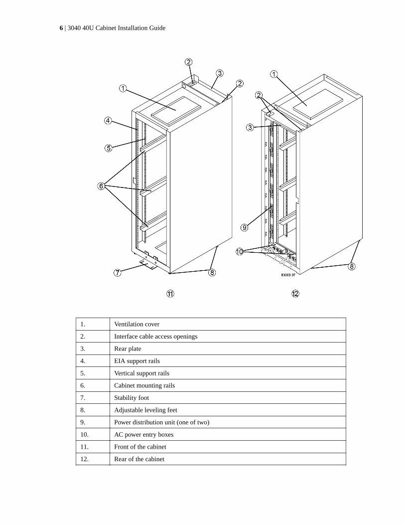
1. Ventilation cover
2. Interface cable access openings
3. Rear plate
4. EIA support rails
5. Vertical support rails
6. Cabinet mounting rails
7. Stability foot
8. Adjustable leveling feet
9. Power distribution unit (one of two)
10. AC power entry boxes
11. Front of the cabinet
12. Rear of the cabinet
6 | 3040 40U Cabinet Installation Guide

Power requirements and heat dissipationThe 3040 40U cabinet is rated at 200 VAC to 240 VAC at 50 Hz to 60 Hz, and it operates to ±10percent of that range. The cabinet includes two identical AC power distribution units (PDUs), witheach PDU providing up to 72A of usable power. The PDUs are mounted vertically at the back of thecabinet, and each PDU includes six 12A power banks. Each power bank contains four IEC 60320-C19 power outlets and a 15A circuit breaker. Each PDU has a total of 24 outlets and 6 circuitbreakers.
Each of the two PDUs has three power entry boxes, which are located at the bottom of the cabinet.Each power entry box provides power to eight of the power outlets, as follows:
• Power entry box 1, which has power cord C1, supplies power to the bottom eight outlets
• Power entry box 2, which has power cord C2, supplies power to the middle eight outlets
• Power entry box 3, which has power cord C3, supplies power to the top eight outlets
The power entry boxes are labeled C1, C2, and C3 where the power cords connect to the modules.
Table 1: Power calculations and heat calculations for the cabinet
Component kVA Watts BTU/Hr
Cabinet PDU (72A PDUs) 14.4 14400 49176
Cabinet PDU/12A bank (72A PDUs) 2.40* 2400* 8196*
E2612 controller-drive tray 0.437 433 1476
E2624 controller-drive tray 0.487 482 1644
E2660 controller-drive tray 1.128 1117 3810
E2712 controller-drive tray 0.516 511 1744
E2724 controller-drive tray 0.561 555 1894
E2760 controller-drive tray 1.205 1193 4072
E5412 controller-drive tray 0.558 552 1883
E5424 controller-drive tray and the EF540flash array
0.607 601 2051
E5460 controller-drive tray 1.254 1242 4237
E5512 controller-drive tray 0.587 581 1982
E5524 controller-drive tray and the EF550flash array
0.637 630 2150
E5560 controller-drive tray 1.285 1272 4342
E5612 controller-drive tray 0.625 619 2111
E5624 controller-drive tray and the EF560flash array
0.675 668 2279
E5660 controller-drive tray 1.325 1312 4477
DE1600 drive tray 0.325 322 1099
DE5600 drive tray 0.375 371 1267
Specifications of the model 3040 40U cabinet | 7

Component kVA Watts BTU/Hr
DE6600 drive tray 0.1.011 1001 3415
* The maximum ratings at 200 VAC. The BTU calculation is based on the maximum current ratingthat the power distribution unit can provide.
Maximum number of traysThe maximum number of trays that you can install in a 3040 40U cabinet depends on the height ofeach tray in rack units (U). Each rack unit is 1.75 inches (4.45 cm). For example, you can install upto ten 4U trays, up to twenty 2U trays, or a combination of 2U and 4U trays, up to 40U.
Table 2: Tray heights in rack units (U)
Tray Rack units (U)
E2x12 or E2x24 controller-drive tray 2U
E2x60 controller-drive tray 4U
E5x12 or E5x24 controller-drive tray 2U
E5x60 controller-drive tray 4U
EF5x0 Flash Array 2U
DE1600 drive tray 2U
DE5600 drive tray 2U
DE6600 drive tray 4U
8 | 3040 40U Cabinet Installation Guide
Installing the cabinet
Because the cabinet is a large and heavy piece of equipment, cabinet installation requires planningwith attention to detail during the installation process.
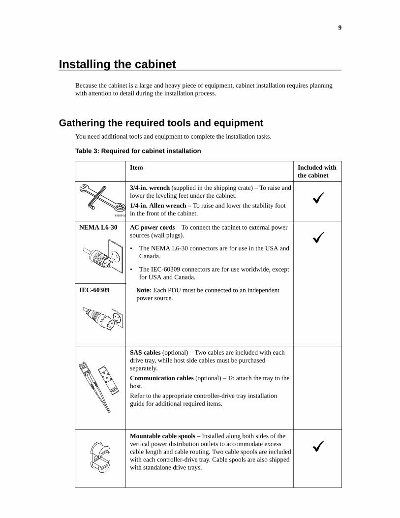
Gathering the required tools and equipmentYou need additional tools and equipment to complete the installation tasks.
Table 3: Required for cabinet installation
Item Included withthe cabinet
83009-02
3/4-in. wrench (supplied in the shipping crate) – To raise andlower the leveling feet under the cabinet.
1/4-in. Allen wrench – To raise and lower the stability footin the front of the cabinet.
NEMA L6-30 AC power cords – To connect the cabinet to external powersources (wall plugs).
• The NEMA L6-30 connectors are for use in the USA andCanada.
• The IEC-60309 connectors are for use worldwide, exceptfor USA and Canada.
Note: Each PDU must be connected to an independentpower source.
IEC-60309
SAS cables (optional) – Two cables are included with eachdrive tray, while host side cables must be purchasedseparately.
Communication cables (optional) – To attach the tray to thehost.
Refer to the appropriate controller-drive tray installationguide for additional required items.
Mountable cable spools – Installed along both sides of thevertical power distribution outlets to accommodate excesscable length and cable routing. Two cable spools are includedwith each controller-drive tray. Cable spools are also shippedwith standalone drive trays.
9

Item Included withthe cabinet
Shears – To cut the metal bands on the shipping crate.
Forklift (optional) – To remove the cabinet from theshipping pallet.
Front panel kits (optional) – To cover the empty bays at thefront of the cabinet.
Antistatic bags (optional) – To protect components that areremoved during the installation procedure for the cabinet.
Preparing to move the cabinetBefore you move the cabinet from its location in your receiving area, you must complete these tasks:
1. Estimate the total weight of the cabinet and the trays that are to be installed in it.
2. Acclimate the cabinet.
3. Remove the packing materials.
4. Check the shipping contents.
5. Remove selected components from the cabinet.
Estimating the cabinet weight
The cabinet reliably and safely transports up to 909.1 kg (2000 lb) of capacity. You need to know theapproximate weight of the cabinet so that you can safely move it.
Caution: Remove all drives from the DE6600 drive tray before moving the cabinet to its finalposition.
Attention: Possible equipment damage – Cabinets with DE6600 drive trays ship without drivesto reduce shipping weight. Because a fully-populated cabinet with DE6600 drive trays can weighmore than 1247.3 kg (2750 lb), make sure that you move the cabinet into place before you load thedrives, and make sure that the floor load capability of the cabinet’s destination supports that muchweight.
Attention: Possible damage to tray components – Do not place a DE6600 drive tray on a flatsurface. Install the DE6600 drive tray in the cabinet before operating or moving drawers.
The total weight of the cabinet depends on the number and type of trays that are installed in thecabinet. The following table lists the weights of the components that might be installed in the cabinetand the weight of the empty cabinet. Use this table to calculate the approximate total weight of yourcabinet. Make sure that you have adequate personnel and equipment to safely move the cabinet.
Note: For more detailed descriptions of the controller-drive trays, flash arrays, and drive trayslisted below, refer to the Storage System Site Preparation Guide or the appropriate controller-drivetray installation guide.
Table 4: Cabinet and tray weights
Component Weight Notes
Cabinet 138.80 kg (306.0 lb) Empty with the rear door installed
10 | 3040 40U Cabinet Installation Guide

Component Weight Notes
Power distribution units (PDUs[pair])
19.96 kg (44.0 lb)
Mounting rails (pair) 1.59 kg (3.50 lb)
E2612 controller-drive tray 27 kg (59.52 lb) Maximum configuration
E2624 controller-drive tray 26.12 kg (57.32 lb) Maximum configuration
E2660 controller-drive tray 105.2 kg (232 lb) Maximum configuration
E2712 controller-drive tray 27.12 kg (59.8 lb) Maximum configuration
E2724 controller-drive tray 26 kg (57.32 lb) Maximum configuration
E2760 controller-drive tray 105.2 kg (232 lb) Maximum configuration
E5412 controller-drive tray 27.92 (61.52 lb) Maximum configuration
E5424 controller-drive tray 26.92 kg (59.32 lb) Maximum configuration
E5460 controller-drive tray 105.2 kg (232 lb) Maximum configuration
E5512 controller-drive tray 28.89 kg (63.7 lb) Maximum configuration
E5524 controller-drive tray 27.9 kg (61.52 lb) Maximum configuration
E5560 controller-drive tray 107.13 kg (236.2 lb) Maximum configuration
E5612 controller-drive tray 28.89 kg (63.7 lb) Maximum configuration
E5624 controller-drive tray 27.9 kg (61.52 lb) Maximum configuration
E5660 controller-drive tray 107.13 kg (236.2 lb) Maximum configuration
EF540 flash array 23.64 kg (52.12 lb) Maximum configuration
EF550 flash array 24.63 kg (54.32 lb) Maximum configuration
EF560 flash array 24.63 kg (54.32 lb) Maximum configuration
DE1600 drive tray 26.3 kg (58 lb) Maximum configuration
DE5600 drive tray 25.31 kg (55.8 lb) Maximum configuration
DE6600 drive tray 104.1 kg (229.6 lb) Maximum configuration
Acclimating the cabinet
Attention: Possible damage to tray components – If the outdoor temperature is below 0°C(32°F) when you receive your cabinet and trays, do not immediately unpack them or uncrate them.Exposing cold components to warm indoor temperatures can cause condensation, which results incomponent damage or failures.
Make sure that the cabinet and the trays are acclimated to the indoor environment before removingthe packing materials. If the outdoor temperature is below 0°C (32°F), leave the cabinet and traysinside of their crates indoors for at least 24 hours to prevent condensation. Increase or decrease the24-hour stabilization period depending on the outside temperature upon arrival. After the cabinet andthe trays have acclimated to the indoor environment, you can unpack them.
Removing the packing material
After the cabinet has acclimated to the indoor temperature, refer to the unpacking instructionsincluded on the front of the shipping crate, and remove the packing material.
Installing the cabinet | 11
Checking the shipping contents
Compare the packing list with the equipment that you received to make sure that all equipmentarrived at the site. If any items are missing, contact your sales representative.
Removing the components
Before you move the cabinet, remove some of the heavier components that are located in the top ofthe cabinet. Removing these components ensures maximum stability and keeps the center of gravityas close to the floor as possible while the cabinet is being moved. Make sure the maximum weightdoes not exceed 2000 lbs before you move the cabinet.
About this task
After the cabinet is moved to its permanent location, you will reinstall these components in thecabinet in their original locations. Make sure that you note the location of each component beforeyou remove it.
Attention: Possible address conflict of loss of data access – To prevent address conflicts and lossof data access, note the location of each tray, component, and cable before removing it, so that youcan reinstall each item in its original location.
Steps
1. Record the cable configuration for future reassembly if any cables must be disconnected.
2. Remove the drive trays and controller-drive trays in the top half of the cabinet. Keep all of thecomponents from the same tray together.
Note: You do not need to remove the power supplies or other components from the rear of eachtray.
3. Place each component in a separate antistatic bag. If the original shipping boxes are available, usethem to transport the components.
Moving the cabinetThe 3040 40U cabinet has heavy-duty casters that enable you to move the cabinet to its permanentlocation.
About this task
Shipping crates provide built-in ramps and instructions for rolling the cabinet off the pallet withoutthe use of a forklift. Refer to the unpacking instructions included on the front of the shipping crate.
When you move a cabinet, you must be aware of all of the ramps between the loading dock and thedestination. You must evaluate all ramps to make sure that the cabinet’s center of gravity (when thecabinet is on a ramp and sitting at an angle) does not extend beyond the cabinet’s footprint.
Remove the top-most devices in your cabinet to make sure that the cabinet is safely transported to itsfinal location. This is especially important if any ramp has an incline or a decline greater than 10degrees.
Note: Many of the cabinets are populated with drive trays. This situation results in most of theweight in the front portion of the cabinet, making the center of gravity closer to the front.
Move the cabinet to its permanent location using the correct method shown in the following figure.Make sure that you push on the front of the cabinet, not the rear.
12 | 3040 40U Cabinet Installation Guide

Installing the cabinet | 13

Completing the installation
After you move the cabinet, you lower the leveling feet and the stability foot, reinstall thecomponents you removed, and install other required components.
Lowering the leveling feet and the stability footThe stability foot prevents the cabinet from falling over after it is placed in its permanent location.After you move the 3040 40U cabinet to its permanent location, lower the leveling feet to support thecabinet off of the casters. Make sure that the cabinet is a level as possible. The leveling feet arelocated near each bottom corner of the cabinet. The following figure provides a close-up view of thestability foot and the leveling feet.
1. Leveling feet
14

2. Stability foot
Reinstalling the traysAfter you move the cabinet, you can reinstall the trays in their original locations.
About this task
Attention: Possible equipment damage – Do not install a DE6600 drive tray, an E2660controller-drive tray, an E2760 controller-drive tray, an E5460 controller-drive tray, E5560controller-drive tray, or an E5660 controller-drive tray in the top of the cabinet over your head.When fully-populated, each of these trays weighs over 100 kg (220 lb). If installed in the top of thecabinet, the trays will create a top-heavy cabinet that can become easily unbalanced.
Warning: (W15) Risk of bodily injury – An empty tray weighs approximately 56.7 kg (125 lb).Three persons are required to safely move an empty tray. If the tray is populated with components,a mechanized lift is required to safely move the tray.
Attention: Possible address conflict or loss of data access – To prevent address conflicts and lossof data access, replace all components in the same tray and in the same location in the tray.Reinstall all trays in their original locations in the cabinet. Reinstall all cables in their originallocations in the cabinet.
Steps
1. Reinstall all of the trays in their original locations in the cabinet.
2. Reinstall all of the components in their original locations in the trays.
3. Reinstall all cables to their original locations in the trays.
4. Route the interface cables to the cabinet.
5. Route the main power cords from the cabinet to the two external power sources. Do not plug inthe power cords at this time.
Completing the installation | 15

Installing the cable spools and the tie wrapsAfter you reinstall the trays, you install the cable spools and the tie wraps along both sides of thevertical power distribution outlets. The cable spools and the tie wraps accommodate excess cablelength and cable routing for the controllers and the trays.
About this task
1. Tie wrap location
2. Cable spool
Installing other componentsYou can install additional trays. You must cover unused positions for trays to assure correct air flow.
Steps
1. If you have additional trays that must be installed, install the mounting hardware for these trays.
2. If the front of the cabinet is not completely filled with trays, use front panel kits to cover theempty spaces above or below the installed trays.
Covering the empty spaces is necessary so that the correct airflow through the cabinet ismaintained.
16 | 3040 40U Cabinet Installation Guide

3. Refer to the controller-drive tray installation guides for the trays that are contained in the cabinet,and complete the power-on procedures described in the guides.
Completing the installation | 17

Installing additional mounting rails
If you are installing controller-drive trays, or drive trays that were shipped separately (not alreadyinstalled in the cabinet), you might need to install additional mounting rails in the cabinet.
Steps
1. Determine the location for the mounting rails.
• Above an existing tray – Position the mounting rails immediately above the top tray in thecabinet.
• Beneath an existing tray – Position the mounting rails with enough clearance to hold the traybeing installed:
◦ 8.9 cm (3.5 in.) for 2U controller-drive trays or drive trays
◦ 17.8 cm (7 in.) for 4U controller-drive trays or drive trays
2. Use the measurement markers on the right-front and left-front vertical supports to attach themounting rails to the same position on each side of the cabinet.
18
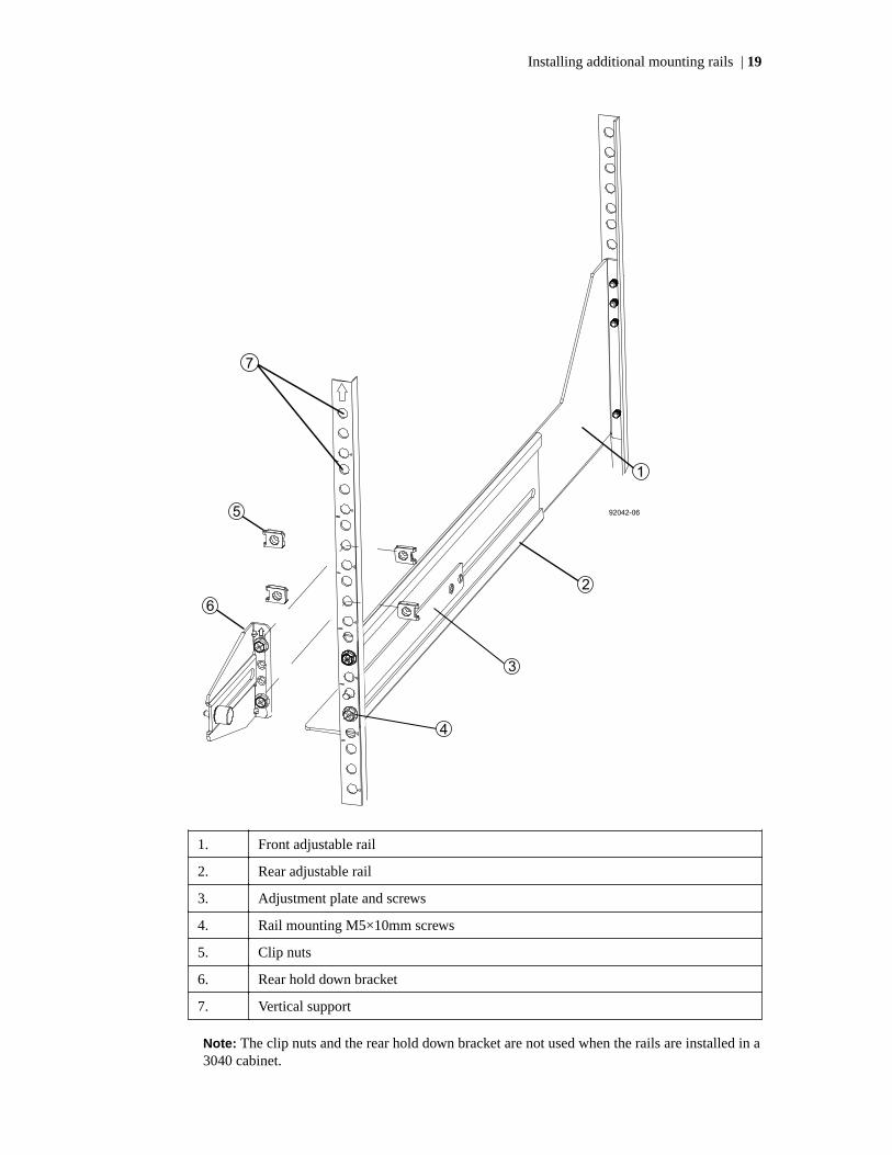
1. Front adjustable rail
2. Rear adjustable rail
3. Adjustment plate and screws
4. Rail mounting M5×10mm screws
5. Clip nuts
6. Rear hold down bracket
7. Vertical support
Note: The clip nuts and the rear hold down bracket are not used when the rails are installed in a3040 cabinet.
Installing additional mounting rails | 19

3. Place the rear adjustable rail on the vertical support.
4. On the rear adjustable rail, align the adjustable rail holes in front of the holes in the verticalsupport.
5. Attach two M5×10mm screws.
a. Attach the screws through the vertical support rail and the rear adjustable rail.
b. Tighten the screws.
6. Place the front adjustable rail on the vertical support.
7. On the front adjustable rail, align the adjustable rail holes in front of the holes in the verticalsupport.
8. Attach two M5×10mm screws.
a. Attach one screw through the vertical support rail and the bottom hole of the front adjustablerail.
b. Attach one screw through the vertical support rail and the middle of the top three holes in thefront adjustable rail.
c. Tighten the screws.
Note: The remaining two screw holes are used to mount the tray.
9. Repeat step 3 through step 8 to attach the second rail on the other side of the cabinet.
10. Install each tray using the applicable tray installation instructions.
11. Choose one of the following options:
• If all positions for trays are full, refer to the controller-drive tray installation guide for eachtray that is contained in the cabinet, and complete the power-on procedures described in theguides.
• If not all positions for trays are full, use front panel kits to cover the empty spaces above orbelow the installed trays.
20 | 3040 40U Cabinet Installation Guide
Turning on the power with 72A PDUs
Power to trays is provided by a standard AC power source. This topic describes how to connect thecabinet to power.
About this task
While the trays perform the power-on procedure, the LEDs on the front and the rear of the traysblink. Depending on your configuration, it can take several minutes to complete the power-onprocedure.
Steps
1. Turn off the power to all of the components in the cabinet.
2. Turn all 12 circuit breakers to their off (down) position.
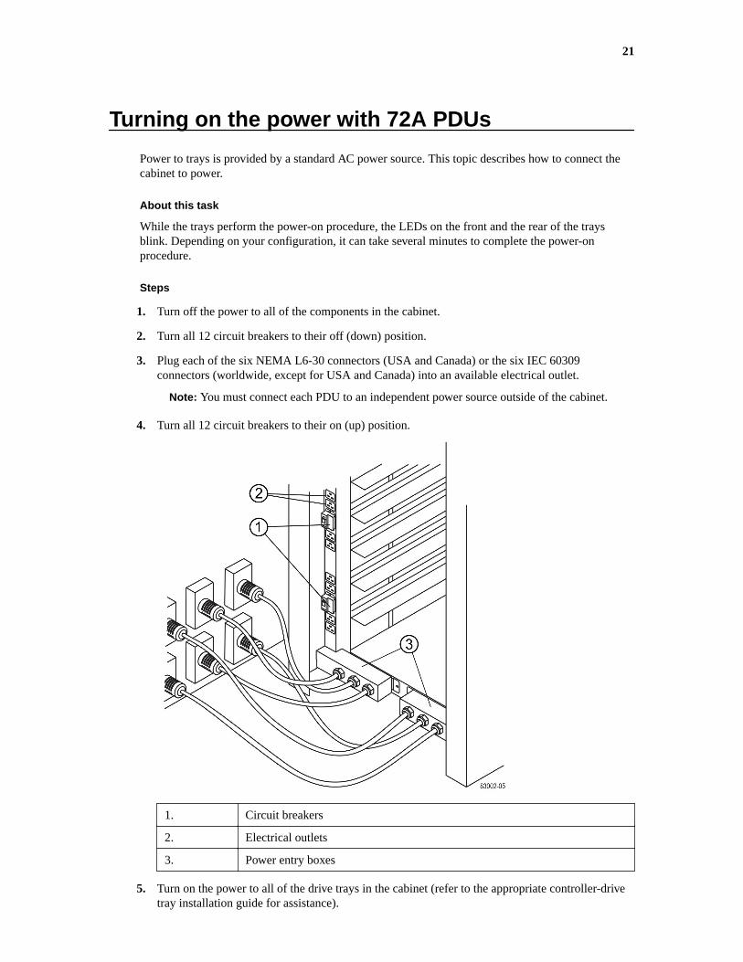
3. Plug each of the six NEMA L6-30 connectors (USA and Canada) or the six IEC 60309connectors (worldwide, except for USA and Canada) into an available electrical outlet.
Note: You must connect each PDU to an independent power source outside of the cabinet.
4. Turn all 12 circuit breakers to their on (up) position.
1. Circuit breakers
2. Electrical outlets
3. Power entry boxes
5. Turn on the power to all of the drive trays in the cabinet (refer to the appropriate controller-drivetray installation guide for assistance).
21

Important: Wait 30 seconds after turning on the drive trays before you turn on the power to thecontroller-drive trays.
6. Turn on the power to all of the controller-drive trays in the cabinet (refer to the appropriatecontroller-drive tray installation guide for assistance).
22 | 3040 40U Cabinet Installation Guide

Copyright information
Copyright © 1994–2016 NetApp, Inc. All rights reserved. Printed in the U.S.
No part of this document covered by copyright may be reproduced in any form or by any means—graphic, electronic, or mechanical, including photocopying, recording, taping, or storage in anelectronic retrieval system—without prior written permission of the copyright owner.
Software derived from copyrighted NetApp material is subject to the following license anddisclaimer:
THIS SOFTWARE IS PROVIDED BY NETAPP "AS IS" AND WITHOUT ANY EXPRESS ORIMPLIED WARRANTIES, INCLUDING, BUT NOT LIMITED TO, THE IMPLIEDWARRANTIES OF MERCHANTABILITY AND FITNESS FOR A PARTICULAR PURPOSE,WHICH ARE HEREBY DISCLAIMED. IN NO EVENT SHALL NETAPP BE LIABLE FOR ANYDIRECT, INDIRECT, INCIDENTAL, SPECIAL, EXEMPLARY, OR CONSEQUENTIALDAMAGES (INCLUDING, BUT NOT LIMITED TO, PROCUREMENT OF SUBSTITUTEGOODS OR SERVICES; LOSS OF USE, DATA, OR PROFITS; OR BUSINESS INTERRUPTION)HOWEVER CAUSED AND ON ANY THEORY OF LIABILITY, WHETHER IN CONTRACT,STRICT LIABILITY, OR TORT (INCLUDING NEGLIGENCE OR OTHERWISE) ARISING INANY WAY OUT OF THE USE OF THIS SOFTWARE, EVEN IF ADVISED OF THEPOSSIBILITY OF SUCH DAMAGE.
NetApp reserves the right to change any products described herein at any time, and without notice.NetApp assumes no responsibility or liability arising from the use of products described herein,except as expressly agreed to in writing by NetApp. The use or purchase of this product does notconvey a license under any patent rights, trademark rights, or any other intellectual property rights ofNetApp.
The product described in this manual may be protected by one or more U.S. patents, foreign patents,or pending applications.
RESTRICTED RIGHTS LEGEND: Use, duplication, or disclosure by the government is subject torestrictions as set forth in subparagraph (c)(1)(ii) of the Rights in Technical Data and ComputerSoftware clause at DFARS 252.277-7103 (October 1988) and FAR 52-227-19 (June 1987).
23

Trademark information
NetApp, the NetApp logo, Go Further, Faster, AltaVault, ASUP, AutoSupport, Campaign Express,Cloud ONTAP, Clustered Data ONTAP, Customer Fitness, Data ONTAP, DataMotion, Fitness, FlashAccel, Flash Cache, Flash Pool, FlashRay, FlexArray, FlexCache, FlexClone, FlexPod, FlexScale,FlexShare, FlexVol, FPolicy, GetSuccessful, LockVault, Manage ONTAP, Mars, MetroCluster,MultiStore, NetApp Insight, OnCommand, ONTAP, ONTAPI, RAID DP, RAID-TEC, SANtricity,SecureShare, Simplicity, Simulate ONTAP, Snap Creator, SnapCenter, SnapCopy, SnapDrive,SnapIntegrator, SnapLock, SnapManager, SnapMirror, SnapMover, SnapProtect, SnapRestore,Snapshot, SnapValidator, SnapVault, StorageGRID, Tech OnTap, Unbound Cloud, and WAFL andother names are trademarks or registered trademarks of NetApp, Inc., in the United States, and/orother countries. All other brands or products are trademarks or registered trademarks of theirrespective holders and should be treated as such. A current list of NetApp trademarks is available onthe web.
http://www.netapp.com/us/legal/netapptmlist.aspx
24

How to send comments about documentation andreceive update notifications
You can help us to improve the quality of our documentation by sending us your feedback. You canreceive automatic notification when production-level (GA/FCS) documentation is initially released orimportant changes are made to existing production-level documents.
If you have suggestions for improving this document, send us your comments by email.
To help us direct your comments to the correct division, include in the subject line the product name,version, and operating system.
If you want to be notified automatically when production-level documentation is released orimportant changes are made to existing production-level documents, follow Twitter account@NetAppDoc.
You can also contact us in the following ways:
• NetApp, Inc., 495 East Java Drive, Sunnyvale, CA 94089 U.S.
• Telephone: +1 (408) 822-6000
• Fax: +1 (408) 822-4501
• Support telephone: +1 (888) 463-8277
25