e-series operators manual - diagraph.com · employs a hardware-specific design, thus increasing...
TRANSCRIPT

Operator’s Manual
6000-010Revision E
PA/4600EPA/6000E
Operator’s Manual
PA/4600EPA/6000E

Diagraph - an ITW Company E-Series User Manual Revision E
Diagraph, an ITW company, continually improves itsproducts, and reserves the right to change or discon-tinue specifications and designs shown in this manualwithout notice and without incurring obligation.Diagraph has made every effort to verify the informa-tion contained in this manual, but reserves the right tocorrect any error at the time of the manual’s nextrevision.© 2010 Illinois Tool Works Inc. All rights reserved.Printed in the United States of America
Page 1

Diagraph - an ITW Company E-Series User Manual Revision E
1.0 Introduction
1.1 The PA/4600E and PA/6000E Printer - Applicators
The PA/4600E and PA/6000E are seventh generation, next label out, print and apply labelers designed for modularity, continuous labeling, self-diagnostics, and ease of use. Modularity of design provides the basis for ease of installation, setup, and maintenance. The electronics systememploys a hardware-specific design, thus increasing reliability and throughput. The hardware was developed to simplify construction, and increaselongevity by using durable materials. These units will perform 24/7 operation in harsh environments and operate trouble-free, given that theappropriate preventative maintenance is performed on regular service intervals.
1.2 Product Safety
Safety awareness is critical when working with equipment that contains moving parts and extending electric actuators. Please read all warnings andcautions thoroughly before operating this device.
This product meets the requirements of CAN/CSA-22.2 NO.60950-00 * UL 60950 using Diagraph an ITW Company approved items. Units are onlytested and qualified with Diagraph an ITW Company approved parts and accessories. Use of other parts or accessories may introduce potential risksthat Diagraph an ITW Company can assume no liability for.
WARNINGS
• WARNING - Moving parts of this machine can present hazards. Components that cannot be guarded because of loss offunctionality are marked with a warning symbol.
• Be aware of the actuator extension distance, and avoid accidental triggering of the photosensor.
• When servicing the unit’s electronic assemblies, always remove the power cord from the unit to prevent accidental shock.
• When running for extended periods of time, use caution when accessing the drive module circuitry. The motor drive powertransistors, motor case, and motor heatsink can become hot under constant use.
• Wear personal protective equipment, as instructed by your supervisor, when operating or working near this device.
COMPLIANCE
• CAUTION: Not for use in a computer room as defined in the Standard for the Protection of Electronic Computer/ DataProcessing Equipment, ANSI/NFPA 75.
• ATTENTION: Ne peut être utilissé dans une salle d’ordinateurs telle que définie dans las norme. ANSI/NFPA 75 Standardfor the Protection of Electronic Computer/ Data Processing Equipment
• This unit has been tested and found to comply with the limits for a Class A device, pursuant to part 15 of the FCC Rules.
Introduction Page 2

Diagraph - an ITW Company E-Series User Manual Revision E
• This unit has been tested to comply with CE Standards.
• This unit is equipped with an Emergency Stop switch. Depressing this switch will cause all machine operations to cease.
• This unit was tested and it was determined that a potential for tipping exists in certain orientations. In compliance with ULsafety standards, the stand must be secured to the surface where it is located. Additionally, this type of securing will resultin greater product application accuracy.
1.3 Warranty Information
The PA/4600E and PA/6000E labelers, including all components unless otherwise specified, carry a limited warranty. For all warranty terms andconditions, contact Diagraph, an ITW Company, for a complete copy of the Limited Warranty Statement.
1.4 Specifications
General Specifications
Category Parameter
Dimensions (with Yoke) 31 in. (787 mm) L x 27 in. (686 mm) H x 26 in. (660 mm) D
WeightE-TAMP, E-WASAE-FASAChi-Stand
120 lbs (54.4 kg) (includes yoke, no stand)130 lbs (58.9 kg) 96 lbs (43.5 kg)
Accuracy ±0.06 in. (±1.6 mm)
Certifications Œ, CSA, FCC approved, Listed (UL 60950)
Supply Roll CapacityPA/4600EPA/6000E
13 in. (330.2 mm) OD with a 3 in. (76.2 mm) ID Core14 in. (355.6 mm) OD with a 3 in. (76.2 mm) ID Core
Label Length 0.5 in. (12.7 mm) Min. to 14.0 in. (355.6 mm) Max.
Label Width 0.5 in. (12.7 mm) Min. to 6.5 in. (165.1 mm) Max.
Introduction Page 3

Diagraph - an ITW Company E-Series User Manual Revision E
Product RatePA/4600E E-TAMPPA/4600E E-FASA PA/4600E E-WASA
PA/6000E E-TAMPPA/6000E E-FASAPA/4600E E-WASA
50 PPM Max.Single Apply: 38 PPM Max. Dual Apply: 18 PPM Max.Dependent on Label Length, Print Speed, and Product Spacing
120 PPM Max.Single Apply: 52 PPM Max. Dual Apply: 28 PPM Max.Dependent on Label Length, Print Speed, and Product Spacing
LinespeedE-TAMPE-FASAE-WASA
150 FPM Max.75 FPM Max.125 FPM Max.
Temperature 41°F - 104°F (5°C - 40°C)
Humidity 10 to 85% RH, Non-Condensing
Electrical Specifications
Category Nominal Minimum Maximum
AC Voltage Supply 100 - 240 VAC, 1.6A 50/60 Hz
90 VAC47 Hz
264 VAC63 Hz
Product Detector Low: 0 to 3 VDCHigh: 3 to 5 VDCSupplies 24VDC
0 VDC 24 VDC
Product Detector Pulse Width 10 mS 1 mS Infinite
Auxiliary OutputWarning Tower
0 and 24 VDC1 Amp sinking
0 VDC0 mA
24 VDC1.5 Amps sinking
Discrete Inputs (Optional) Low: 0 to 10 VDCHigh: 10 to 24 VDC
0 VDC 26 VDC
Discrete Input Pulse Width Detection
20 mS 3 mS Infinite
Discrete Outputs (Optional) 0 - 24 V AC/DC at 150 mA 0 V AC/DC, 13 ohms 30 V AC/DC at 170 mA
General Specifications
Category Parameter
Introduction Page 4

Diagraph - an ITW Company E-Series User Manual Revision E
Performance Specifications - 10 or 20 in. E-Tamp PA/6000E Labeler
Application Label Size Stroke Distance(Baseplate edge to product)
PPM Maximum
Side Orientation (Nose-Down) 4x2, 10 ips 4 inches, “A5” Actuator Profile 82 PPM
Side Orientation (Nose-Down) 4x2, 12 ips 4 inches, “A5” Actuator Profile 85 PPM
Side Orientation (Nose-Down) 4x2, 12 ips 3 inches, “A5” Actuator Profile 94 PPM
Side Orientation (Nose-Down) 4x2, 12 ips 1.5 inches, “A5” Actuator Profile 102 PPM
Performance Specifications - 10 or 20 in. E-Tamp PA/4600E Labeler
Application Label Size Stroke Distance(Baseplate edge to product)
PPM Maximum
Side Orientation (Nose-Down) 4x2, 6 ips 4 inches, “A5” Actuator Profile 50 PPM
Side Orientation (Nose-Down) 4x2, 6 ips 3 inches, “A5” Actuator Profile 55 PPM
Side Orientation (Nose-Down) 4x2, 6 ips 1.5 inches, “A5” Actuator Profile 60 PPM
Performance Specifications - 10 in. E-FASA PA/6000E Labeler
Application Label Size Stroke Distance(Baseplate edge to product)
PPM Maximum
Dual Panels - Front & Side 4x2, 8 ips 4.5 inches, “A5” Actuator Profile 28 PPM
Dual Panels - Side & Rear 4x2, 8 ips 4.5 inches, “A5” Actuator Profile 24 PPM
Single Panel - Front Only 4x2, 8 ips 4.5 inches, “A5” Actuator Profile 52 PPM
Single Panel - Rear Only 4x2, 8 ips 4.5 inches, “A5” Actuator Profile 46 PPM
Dual Panels - Front & Side 4x6, 8 ips 4.5 inches, “A5” Actuator Profile 18 PPM
Dual Panels - Side & Rear 4x6, 8 ips 4.5 inches, “A5” Actuator Profile 16 PPM
Single Panel - Front Only 4x6, 8 ips 4.5 inches, “A5” Actuator Profile 44 PPM
Single Panel - Rear Only 4x6, 8 ips 4.5 inches, “A5” Actuator Profile 40 PPM
Introduction Page 5

Diagraph - an ITW Company E-Series User Manual Revision E
Performance Specifications - 20 in. E-FASA PA/6000E Labeler
Application Label Size Stroke Distance(Baseplate edge to product)
PPM Maximum
Dual Panels - Front & Side 4x6, 8 ips 14 inches, “A2” Actuator Profile 10 PPM
Dual Panels - Side & Rear 4x6, 8 ips 14 inches, “A2” Actuator Profile 12 PPM
Single Panel - Front Only 4x6, 8 ips 14 inches, “A2” Actuator Profile 26 PPM
Single Panel - Rear Only 4x6, 8 ips 14 inches, “A2” Actuator Profile 24 PPM
Performance Specifications - E-WASA PA/6000E Labeler
Application Print Speed PPM Maximum
6 inch Length WASA 8 ips 11
8 inch Length WASA 8 ips 10
10 inch Length WASA 8 ips 9
12 inch Length WASA 8 ips 8
Introduction Page 6

Diagraph - an ITW Company E-Series User Manual Revision E
1.5 System Dimensions - E-TAMP
Min = 30 inMax = 69 in
Min = 11 inMax = 45 in
Min = 13 inMax = 50 in
Min = 24 inMax = 63 in
Side Orientation Top Down
Nose Down Nose UpTop
Side
Overhead
27 in
31 in
27 in
26 in
26 in
31 in
69 in
33 in
47 in
Introduction Page 7

Diagraph - an ITW Company E-Series User Manual Revision E
1.6 System Dimensions - E-FASA 10in.
Side Orientation
Nose Down Nose Up
End Profile
Side
27 in
49 in
21 in
49 in
21 in
27 in
Top
Min = 24 inMax = 63 in
Min = 11 inMax = 45 in
Min = 30 inMax = 69 in
69 in
Introduction Page 8

Diagraph - an ITW Company E-Series User Manual Revision E
1.7 System Dimensions - E-FASA 20in.
Side Orientation
Nose Down Nose Up
Side
End Profile
27 in
59 in
21 in
59 in
27 in
21 in
Top
Min = 11 inMax = 45 in
Min = 30 inMax = 69 in
69 in
Min = 24 inMax = 63 in
Introduction Page 9

Diagraph - an ITW Company E-Series User Manual Revision E
1.8 System Dimensions - E-WASA
Side
36 in. for x1231 in
34 in. for x10
32 in. for x830 in. for x6
21 in
31 in
27 in
36 in
End Profile
Min = 24 inMax = 63 in
Min = 3.5 inMax = 42 in
Side Orientation
Top- Down
Introduction Page 10

Diagraph - an ITW Company E-Series User ManualS
ystem M
odulesRevision E
2.0 System Modules - E-TAMP
FRONT
Product Detector
4600-900
• Diffused light sensor• 900 mm range• Light or Dark
Operate• NPN Signal
* Tamp Pad Sensors
6000-903
• Label Present sees label• Auto-Retract sees product• Focused beam• Shielded, high flex PUR
cabling, M8 Connector
* Warning Tower
6000-828
• Red, Yellow, and Green LED bulbs
• 24 VDC 5W
Air Assist Module
6000-666 [L or R]
• Blower fan to guide label to Tamp Pad
• BLDC Blower Fan• Swings out of the
way for webbing liner
Unwind Supply Roll• Indestructible ABS Material• 14 in. (355 mm) Disk• 3 in. (76 mm) ID Core
4600-605Dancer Arm
• Non-rotating spindle 4600-643• Performs label/liner braking
4600-617Rewind Liner Take-Up• Indestructible ABS 1-pc Material• Simple clasp liner keep
4600-606
User Interface
4600-200
• 128x64 LCD Graphics• Touch Screen• Tri-Color• Remote Tether Option
E-Tamp Actuator
6000-620 x10 or x20
• 10 or 20 inch variable stroke lengths• IGUS Energy chain guarding• Brushless DC Servo motor• Articulated pivoting pad knuckle
OEM Industrial Printers• SATO and Zebra Print Engines• Can be changed from print and
apply to Label Applicator with Drive Module
* = Denotes Optional Equipment
System Modules - E-TAMP Page 11

Diagraph - an ITW Company E-Series User ManualS
ystem M
odulesRevision E
REAR
* Label Low Sensor
6000-903
• Signals warning when supply roll is reaching the end
• Adjustable positions for triggering sooner or later into the roll
MCM
6000-550
• Motor Control Module• Handles actuator and
fan controls• Has internal power
supply for high-speed movements
Power Supply
4600-522
• AutoRanging Voltage• Protected against
surges, spikes, and transients
• Low voltage to electrical enclosure for greater safety
Rewind Motor
4600-503
• Brushless DC Motor• No clutch rewind
eliminates adjustments and wear items
• Keeps up with the fastest print speeds
MCA
* Tube Stand
6160-329
• T-Base stand w/casters• High Tensile Strength Steel• Aluminum travel plate• Mounting locations for
options, such as remote user interface
* = Denotes Optional Equipment
4600-500
• Main Controller Assembly• Contains LCD Display• Microprocessor-based
real-time control• Replacement CPU 4600-
951
* Stand Cleats
4600-622
• Allows labeler to easily be removed and replaced at the line by locating the casters in position
• Prevents any accidental tipping of the labeler stand
System Modules - E-TAMP Page 12

Diagraph - an ITW Company E-Series User ManualS
ystem M
odulesRevision E
3.0 System Modules - E-WASA
Overview
Fan Box
* 6170-502-WxL (R/L)
• Curved surface to allow system to be positioned at line in minimal space
• Moves away from the product to avoid wear
Fan Assembly
6170-509
• Fan generates the label holding force prior to application
• Easily removed for service and cleaning
Adjustable Cylinder
6170-515
• Adjusts for various weight products• Maximizes the wrap around the
corner• Allows the corner wrap fan assembly
to come settle at home
Mount
* 6170-501-WxL (R/L)
• Mounts the support arms to the dovetail track
Support Arms
* 6170-505-WxL
• 4 and 6 inch widths• Retains brush and roller• Performs the product’s corner wrap
* Note - W in the part number is widthStandard widths: 2, 4, 6
L in the part number is lengthStandard lengths: 6, 8, 10, 12
System Modules - E-WASA Page 13

Diagraph - an ITW Company E-Series User ManualO
ptional Equipm
entRevision E
4.0 Optional Equipment
6000-420 Wired/Wireless Ethernet Module
Provides wired Ethernet connectivity with 10/100BaseT andwireless 802.11g capability on the same module. Labelformats, status information, and printer functions can beperformed by Ethernet with this option.
6145-405 Discrete I/O Module
This module provides four (4) optically-isolated inputsand six (6) isolated solid-state outputs. These I/O linesare event driven by selections made by the operatorthrough the user interface. The connection can be madedirectly to a DB25 connector or the Phoenix breakoutscrew terminal connector that mates to the DB25.
6000-903 Auto Retract, Label Present, and Label Low Sensors
The Auto Retract sensor detects the product’s surfacebefore contact to allow light touch or varying size (height orwidth) applications.The Label Present sensor detects the label on the pad tostop the labeler from applying the wrong label to asequenced product. It will generate another label if one isremoved from the pad prior to application, and stops thegeneration of another label if one is already on the pad.The Label Low sensor is used to signal the operator that theconsumable label roll is low and will require replacementsoon.
4600-9014600-902
Product Detectors - Break-Beam & Laser
The standard diffuse light sensor works well for standardcorrugate, but for shrink wrapped pallets the 4600-901Break-Beam sensor is a better choice. For smallproducts, or better accuracy the 4600-902 Laser sensoris ideal. All sensors have a quick disconnect M8connector, shielded cable, and can be mounted on thebaseplate or on-line with included brackets.
4600-250 Remote Tethered Handheld
Provides 5 feet (1.5 m.) of distance away from the labelerfor operation. Ergonomically designed to fit in the user’shand, this rugged unit can be mounted on the back of thestand or elsewhere to allow easy access. This unit takes theplace of the baseplate mounted display.
6000-8286000-828AUD
Warning Tower
The three (3) segment warning tower visually displaysOnline-Running in green, Warning-Offline in yellow, andError-Offline in red. The tower comes with LED bulbs.The tower is offered with an audible alarm siren for theerror condition with the 6000-828AUD part number.
Optional Equipment Page 14

Diagraph - an ITW Company E-Series User ManualT
heory of Operation
Revision E
5.0 Theory of Operation
Print on Demand
Next Label OutPro’s: Maximum Throughput
Label Print and Tamp Time Drives PPMCon’s: Batch Change Could Leave Mismatched Label On Pad
Slow Product Rates Leave Label Adhesive Exposed Longer
Home Delay
Labeler is placed online The printer immediatelyprints the label if aformat is loaded
The Product Detectortriggers upon detectingthe product
The Product Delay timercounts down toexpiration
The Tamp Actuator isextended to the productto apply the label
The Tamp Actuatorreturns home when thefirst of these occurs:- Tamp Duration Expires- Auto-Retract triggersand delay expires- Hit Sense detectscontact
Home Delay timercounts down toexpiration
Label Present sensorchecked for label. If nolabel is present, nextlabel is fed out and cyclerepeats
Product Delay
Labeler is placed online.The labeler is nowwaiting for eitherDetector 1 or Detector 2(depending on LabelActivation setting in JobSetting Menu).
The Product Detectortriggers upon detectingthe product
The printer beginsfeeding the label and theProduct Delay timercounts down toexpiration
If the label is on the padand ready to be applied,the Tamp Actuator isextended to the productto apply the label. If not,there will be a “TimingViolation”. The ProductDelay must be increasedor print time decreased.
The Tamp Actuatorreturns home when thefirst of these occurs:- Tamp Duration Expires- Auto-Retract triggersand delay expires- Hit Sense detectscontact
Home Delay timercounts down toexpiration
The next label cannot begenerated until theproduct has cleared theProduct Detector
Label Present sensorchecked for label. If alabel is still present, anerror can be set. Thelabeler will not generatea new label on the nextProduct Trigger, but willapply the label
Pro’s: Label Adhesive is Exposed ShorterVacuum Fan Runs Less Often
Con’s: PPM Rate Determined by Product Length and Print TimeRequires Relocating Product Detector or 2nd Detector
Tamp DurationHome Delay
Product Delay
Theory of Operation Page 15

Diagraph - an ITW Company E-Series User ManualS
etupRevision E
6.0 Setup
STEP 1 Determine Labeler Orientation
Orientation View
Nose-Down Apply • Side panel of product is to be labeled
• Placing label close to top edge of product
• Conveyor is low to ground, thus keepingunwind/rewind change out within reach
• Not for applying label toward lower edge ofproduct
• Not for tall conveyors where roll change outwould be difficult
Nose-Up Apply • Side panel of product is to be labeled
• Placing label close to bottom edge ofproduct
• Conveyor is standard height, thus keepingunwind/rewind change out within reach
• Not for applying label toward upper edge ofproduct
• Not for lower height conveyors
• Not for label lengths greater than 6 inches(153 mm.)
Side Orientation • Side panel of product is to be labeled
• Corner wrapped panels
• Label is to be applied in landscapeorientation
• Not for tall conveyors where roll change outwould be difficult
Top-Down / Bottom-Up Apply • Top or Bottom panel of product is to belabeled
• More material handing is required forBottom-Up applications
Setup Page 16

Diagraph - an ITW Company E-Series User ManualS
etupRevision E
STEP 2 Labeler Alignment with Product
Not Parallel
Not Parallel Parallel
Parallel
Optimum Labeling Head PositioningThe labeler should be adjusted for position to the product through the yoke, whichrotates about two axes. The labeler must be rotated on these axes to obtain aparallel surface contact when the tamp pad meets the product’s surface. Thesystems are equipped with an articulated knuckle to accommodate some productskew and variances. The setup should not depend on this small amount of pivotingto avoid the proper alignment of the yoke.
Label Supply Roll PositioningThe labeler will not work properly if the label supply angle is beyond 90 degrees,with respect to the ground. This will allow the label roll to slip off of the labeler andcan cause liner tracking problems within the printer.
90°
0°
Parallel
Parallel
Beyond 90°
Setup Page 17

Diagraph - an ITW Company E-Series User ManualS
etupRevision E
STEP 3 Configure Basic SettingsOne Time Settings (OTS)These screens can only be accessed when powering-up or coming out of Standby. The lower-left square must be pressed when the Versions Screenis momentarily displayed. These values should be preset from the factory, and should not require change.
Communications SettingsAll communication to the printer is directed through the MCA (Main Controller Assembly). When the Wired/Wireless Ethernet Module (6000-420) is used, the correct baudrate must still be selected. The baud rate set in the System Menu should match the printer’s baud rate, and if this is an RS232 connection, the PC/PLC baud must match aswell. Access the System Menu by pressing Settings on the Home Screen. From the Settings Menu, press the System button to access the Baud Rate Screen.
If the Ethernet module has been installed, press the Options button from the Settings Menu. Press the Ethernet button to enter the Ethernet Menus. Enter parameters forEthernet Mode, IP Address, Netmask, Gateway Address, and SSID (if one of the wireless modes is selected).
After the selections have been made, commit the changes when the Home button is pressed. Select Yes when the change settings prompt is displayed. If Wireless networkencryption is to be utilized, it must be done through the HTTP interface to the module. The detailed instructions are located in the Ethernet Module Manual.
System Menu SettingsThe Application Mode, Passcode, Baud Rate, and Auto-Trigger screens are located in the System Menu. The Baud Rate should already be set. The Auto-Trigger screen isonly visible if the system was powered-up in a diagnostic mode. Auto-Trigger is used to continuously cycle the actuator without a product detector.
Baud choices are 9600, 19200, 38400, 57600, and 115.2kThe standard values are:Number of bits: 8Parity: NoneStop bits: 1
* Serial Com must be selected if Ethernet is not to be used
Required for all Ethernet Modes Required for all Ethernet Modes Not required for Ad-Hoc Wireless OnlyEnter with spaces to Left-Justify
Conditionally shownShould be Off for normal operation
A setting of ‘0000’ disablesthe passcode
Select the mode that matchesthe application
Press square to access OTS
Setup Page 18

Diagraph - an ITW Company E-Series User ManualS
etupRevision E
STEP 4 Load the MediaLABEL SUPPLY CHANGEOUTBegin by removing the last supply roll core and remaining label liner from the labeler. Insert the new roll over the unwind fins and press rollfirmly against the unwind disk (A). Remove 2 feet of labels from the liner to create a leader. Route the liner around the dancer arm (B) andfeed into the printer, under spindle (I), for PA/6000E systems. Unlatch the printhead (C) and nip roller arm lever (D). Feed the liner throughthe gap sensor (E), under the printhead, and around the peel blade (F). Be sure to avoid webbing over the air assist blower. Oncearound the peel blade, feed liner through the nip roller arm and close printhead latch and nip roller arm. Take the liner to the rewind (H), anduse the clasp to retain it. With the printer offline, press the feed button to register the first label; before the printer is returned online and thelabeler begins running. The label change out can be accomplished in less than a minute by an experienced user.
RIBBON MATERIAL CHANGEOUTRemove the last ribbon take-up roll from spindle (J), and move the old supply-side core from spindle (I), and place it on spindle (J). Insert the new ribbon, observing the ribbontype (face-in or face-out) on the supply-side spindle (I). Route the ribbon under the printhead support arm, around the ribbon roller (K), and wrap around the take-up spindle(J). Make a few wraps and close the printhead latch. Try a few test feeds before going back online.
SATO Lt408 (4600) SATO M84xxSe (6000) Zebra 110PAX4 (6000)
C
D
E
F
SATO
Lt4
08
SATO
M84
xxSe
Zebr
a 11
0PA
X
J
I
K
AA
BB
HH
II
Setup Page 19

Diagraph - an ITW Company E-Series User ManualS
etupRevision E
The next 2 steps are for E-TAMP Only
Setup Page 20

Diagraph - an ITW Company E-Series User ManualS
etupRevision E
E-TAMP - STEP 5 Alignment of the E-TAMP AssemblyTools Required:• 6 mm Allen Wrench
• 7 mm Open End Wrench
Lineal (X) Position Adjustment• Loosen the two screws (A) [use 6 mm wrench] on the dovetail slider
• Slide assembly in and out from the printer until there is approximately 1/8th inch (3 mm.) ofspace between printer peel blade and tamp pad edge
• Tighten the two screws (A) on the dovetail slider
Lateral (Y) Position Adjustment• Loosen the two screws (B) [use 6 mm wrench] on the tamp actuator L-bracket
• Slide the assembly in and out from the baseplate until the label present sensor is within thefeed position of the label. Line (C) shows the projected path of the label where the labelpresent sensor would be fully covered once the label is printed
• Tighten the two 6 mm. screws (B) on the tamp actuator L-bracket. Keep the actuator parallelto the baseplate during tightening
Height (Z) Position Adjustment• Loosen the 7 mm square head jam screw on the actuator rod end
located by the tamp pad
• Turn the rubber bumper by hand to adjust the tamp pad heightposition. Turn clockwise to decrease height, counter-clockwise toextend height
• The optimum position will be an 1/16th inch (1.5 mm) below the peelblade. This is important in order to stop the label from backfeedinginto the printer and prevent label rotation upon actuator extension
• With the E-Tamp controller on, check the resting position of the pad.Once the proper position is set, tighten the square-headed jam screwto lock the bumper in position. Failure to re-tighten the jam screwwill cause feed errors over time as the bumper becomes loose.
AABBLabel PresentSensor
Label PresentSensor
CC
1/8th (3 mm.)1/8th (3 mm.)
1/16th(1.5 mm.)
1/16th(1.5 mm.)Peel Blade Edge
BELOW EDGEBELOW EDGEPeel Blade Edge
Jam ScrewJam Screw
Bumper Height AdjustBumper Height Adjust
Setup Page 21

Diagraph - an ITW Company E-Series User ManualS
etupRevision E
E-TAMP - STEP 6 Configure the Motor Control ModuleOverviewThe Motor Control Module and E-TAMP System is comprised of these subsystems:
• Linear belt-driven actuator rod with motor housing, bearings, and end travel stop
• Brushless DC Servo motor (same as used on Applicator Rewind)
• High velocity vacuum fan and tamp pad
• Motor Control Module Electronics Assembly
• Air Assist Blower Fan AssemblyAs the label is feeding out of the printer, the air assist blower and vacuum fan are activated to draw the label to the pad and hold it in place for application. When the MCAsends the tamp signal, the actuator is extended to the product. The actuator is returned when the MCA ends the tamp signal or upon product contact, if the Hit Contact modeis enabled. When there is no label detected on the pad for over 5 seconds, the vacuum fan reduces speed to an idle. The blower fan is always active.
Actuator Speed Profile Setting [Ax]There are five actuator speed settings to match the applicationrequirement. See following chart for recommended setting
Vacuum Fan Profile Setting [Fx]There are five vacuum fan profile settings to match the application labelsize. See following chart for recommended setting
Hit Contact Mode Setting [Hx]There are two modes of operation for hit contact mode. A value of ‘1’enables the mode, which will return the actuator to home if product contact is made, thus stopping further extension. This is only useful for Actuator speeds A1, A2, and A3.For speeds that are greater than these, the preferred method is to use the Auto-Retract sensor. The Tamp Duration must be set close to the expected contact point with theproduct to work properly. If the actuator returns home while it should be extending, the system will generate an error. A value of ‘0’ disables this sensing mode.
Ax Profile Application
A1 Pallets, PPM less than 40
A2 Pallets, PPM 20 to 60
A3 Pallets, PPM 20 to 60
A4 PPM greater than 60
A5 PPM greater than 80
Fx Profile Label
F1 Label length > 8 inches
F2 Label length > 8 inches
F3 Label size closely matches pad size (i.e.- 4x6 label on 4x6 pad)
F4 Label area is smaller than pad size by 50% (i.e.- 4x2 label on4x4 pad)
F5 Label area is smaller than pad area by 70% (may require custompad to accommodate)
To change profiles in the Motor Control Module
Press SET button for 1 second for Actuator SpeedOnce the profile number is flashing, press the SET buttonmomentarily to advance through the profile settings. When thedesired value appears, wait for the display to stop flashing toset the value. Re-adjust the Tamp Duration after making speedchanges to avoid stroking actuator to the maximum position.
Press SET button for 2 seconds for Vacuum Fan SpeedOnce the profile number is flashing, press the SET buttonmomentarily to advance through the profile settings. When thedesired value appears, wait for the display to stop flashing toset the value.
Press SET button for 3 seconds for Contact Hit SenseOnce the mode number is flashing, press the SET buttonmomentarily to advance through the profile settings. When thedesired value appears, wait for the display to stop flashing toset the value.
Press SET button momentarily to view settings
Setup Page 22

Diagraph - an ITW Company E-Series User ManualS
etupRevision E
The next 2 steps are for E-FASA Only
Setup Page 23

Diagraph - an ITW Company E-Series User ManualS
etupRevision E
E-FASA - STEP 5a Alignment of the E-FASA AssemblyTools Required:• 6 mm Allen Wrench
• 17 mm Open End Wrench
Lineal (X) Position AdjustmentThe X adjustment provides the in-out adjustment of the E-FASA arm
• Loosen the four screws (A) [use 6 mm wrench] on the dovetail slider
• Slide assembly in and out from the printer until there is approximately 1/8th inch (3 mm) of space between printer peelblade and tamp pad edge
• Tighten the four screws (A) [use 6 mm wrench] on the dovetail slider
Lateral (Y) Position AdjustmentThe Y adjustment provides the alignment of the label feed to the pad for centering
• Loosen the four screws (B) [use 6 mm wrench] on the E-FASA actuator L-bracket
• Slide the assembly in and out from the baseplate until the label present sensor iswithin the feed position of the label. Line (C) shows the projected path of the labelwhere the label present sensor would be fully covered once the label is printed
• Tighten the four screws (B) [use 6 mm wrench] on the tamp actuator L-bracket.Keep the actuator parallel to the baseplate during tightening
X-Adjust Y-Adjust
Setup Page 24

Diagraph - an ITW Company E-Series User ManualS
etupRevision E
E-FASA - STEP 5b Alignment of the E-FASA AssemblyHeight (Z) Position AdjustmentThe Z adjustment controls the pad alignment in relation to the printer
• Loosen the 17mm top bumper jam nut, and then rotate the lower nut to set theheight
• Turn clockwise to decrease height, counter-clockwise to extend height
• The optimum position will be an 1/16th inch (1.5 mm) below the peel blade. This isimportant in order to stop the label from backfeeding into the printer and preventlabel rotation upon actuator extension
• With the E-FASA MCM on, check the resting position of the pad. Once the properposition is set, tighten the jam nuts to lock the bumper in position.
Pad Level AdjustmentThis adjustment allows the pad to be leveled to the label feed path and tocorrect for the rotation of the arm that occurs from the above adjustment
• Loosen the 11/32” nut on the bumper shaft
• Turn clockwise to decrease height, counter-clockwise to extend height
• The optimum position will level out the pad and keep it even with the feed of thelabel
Spring Pivot Tension AdjustmentThis adjustment increases or decreases the rigidity of pad movement forpivoting. Adjust to avoid “slapping” the label onto the side of the product
• Loosen the screw [4 mm wrench] on the spring anchor bracket
• Slide the bracket closer to the pivot to decrease tension, further away to increasethe tension
• Tighten the 4mm. screw once the desired tension is set
Home Sensor AdjustmentThis adjustment allows the system to recognize when the arm is home, andfeed the next label. It also reduces power to the motor once home.
• Loosen the setscrew on the Home Sensor Body with either a 2.5 mm. Allen wrenchor a #1 flat blade screw driver.
• With the arm in the home position, start with the sensor slide out away from thesystem (until light goes off), and then slowly slide the sensor inward until the homesensor lights. Tighten the setscrew.
• Verify that the light goes out when the arm leaves the home position and isapproximately an inch away from the bumper stop.
1/8th (3 mm.)1/8th (3 mm.)
1/16th(1.5 mm.)
1/16th(1.5 mm.)
Peel Blade EdgeBELOW EDGEBELOW EDGEPeel Blade Edge
Z-Adjust
Pad Level
Spring Pivot Tension
Home Sensor
Setup Page 25

Diagraph - an ITW Company E-Series User ManualS
etupRevision E
E-FASA - STEP 6 Configure the Motor Control ModuleOverviewThe Motor Control Module and E-FASA System is comprised of these subsystems:
• Rotational belt-driven actuator rod with motor housing, bearings, and end travel stop
• Brushless DC Servo motor (same as used on Applicator Rewind)
• High velocity vacuum fan and tamp pad
• Motor Control Module Electronics Assembly
• Air Assist Blower Fan AssemblyAs the label is feeding out of the printer, the air assist blower and vacuum fan are activated to draw the label to the pad and hold it in place for application. When the MCAsends the tamp signal, the actuator is extended to the product. The actuator is returned when the MCA ends the tamp signal or upon product contact, if the Hit Contact modeis enabled. When there is no label detected on the pad for over 5 seconds, the vacuum fan reduces speed to an idle. The blower fan is always active.
Actuator Speed Profile Setting [Ax]There are five actuator speed settings to match the applicationrequirement. See following chart for recommended setting
Vacuum Fan Profile Setting [Fx]There are five vacuum fan profile settings to match the application labelsize. See following chart for recommended setting
Hit Contact Mode Setting [Hx]There are two modes of operation for hit contact mode. A value of ‘1’enables the mode, which will return the actuator to home if product contact is made, thus stopping further extension. This is only useful for Actuator speeds A1, A2, and A3.For speeds that are greater than these, the preferred method is to use the Auto-Retract sensor. The Tamp Duration must be set close to the expected contact point with theproduct to work properly. If the actuator returns home while it should be extending, the system will generate an error. A value of ‘0’ disables this sensing mode.
Ax Profile Application
A1 Pallets, PPM less than 10
A2 Pallets, PPM 10 to 40
A3 Pallets, PPM 20 to 60 DO NOT USE FOR 20 INCH
A4 PPM greater than 60 DO NOT USE FOR 20 INCH
A5 PPM greater than 80 DO NOT USE FOR 20 INCH
Fx Profile Label
F1 Label length > 8 inches
F2 Label length > 8 inches
F3 Label size closely matches pad size (i.e.- 4x6 label on 4x6 pad)
F4 Label area is smaller than pad size by 50% (i.e.- 4x2 label on4x4 pad)
F5 Label area is smaller than pad area by 70% (may require custompad to accommodate)
To change profiles in the Motor Control Module
Press SET button for 1 second for Actuator SpeedOnce the profile number is flashing, press the SET buttonmomentarily to advance through the profile settings. When thedesired value appears, wait for the display to stop flashing toset the value. Re-adjust the Tamp Duration after making speedchanges to avoid stroking actuator to the maximum position.
Press SET button for 2 seconds for Vacuum Fan SpeedOnce the profile number is flashing, press the SET buttonmomentarily to advance through the profile settings. When thedesired value appears, wait for the display to stop flashing toset the value.
Press SET button for 3 seconds for Contact Hit SenseOnce the mode number is flashing, press the SET buttonmomentarily to advance through the profile settings. When thedesired value appears, wait for the display to stop flashing toset the value.
Press SET button momentarily to view settings
Setup Page 26

Diagraph - an ITW Company E-Series User ManualS
etupRevision E
The next 2 steps are for E-WASA Only
Setup Page 27

Diagraph - an ITW Company E-Series User ManualS
etupRevision E
E-WASA STEP 5 Alignment of the E-WASATools Required:
6 mm Allen Wrench, 13 mm open-end wrench, 24 mm open-end wrench
Adjust X Position:
• Start by loosening the two 6 mm. screws “Sx” on the slider track• Slide the WASA module over to the printer until there is approximately an 1/8th
inch between the printer’s peel blade and the edge of the Fan Box• Tighten the 6 mm screws in place once the position is set
Adjust Y Position:
• Loosen the 6 mm. screws “Sy” to adjust the WASA module across the width ofthe label
• With the label liner threaded through the system, feed the label out to the fan box• Determine if the WASA module needs to be moved up or down to align the
bottom edge of the WASA (closest to the baseplate) with the feed position of thelabel
• The label must not ride up on the raised edge of the Fan Box• Ensure that the WASA module is aligned parallel with the baseplate
Adjust Rotation Angle Position:
• Loosen nuts “Nz1” (13 mm.) and “Nz2” (24 mm.) on the cylinder• Turn the cylinder body to thread the rod in or out of the coupling to adjust the Z
rotational position of the Fan Box• Adjust the rotation so that the label feeds out to the Fan Box without stalling on
the surface of the face• Tighten both nuts and feed a few labels to determine if position is ideal
Sx
XX
1/8th in.1/8th in.
SyYY
Y
Nz1
ZZ
Nz2
Setup Page 28

Diagraph - an ITW Company E-Series User ManualS
etupRevision E
E-WASA STEP 6 Runtime Adjustments Tools Required:
13 mm. Open-End Wrench, 14 mm. Open-End Wrench, Flat blade screwdriver
Adjust Spring Rate:
• Loosen the Jam Nut with the 13 mm. open-end wrench• Turn the screw (14 mm.) clockwise to increase the spring force and counter-
clockwise to reduce it. Products that are under 5 ~ 10 lbs require less springforce, in order to allow the label to be wrapped without making the product stallon the conveyor. Too light of a spring tension will result in a poorly wrapped label.The full range of spring tension is accomplished within a 2 inch screw threadingdistance.
• WARNING - Do not decrease the spring tension so far that the WASA Fan Boxdoes not consistently return home. If the spring is too weak, friction and productplacement will begin to effect the performance of the label wrap.
• Once the WASA travel has been checked for the swing range of motion, lock in thespring tension position by tightening the jam nut.
Adjust Return Flow Control:
• Loosen the thumb wheel jam nut and turn the flow control clockwise to reducethe speed that the WASA returns to the home position. Increase the flow byturning the control counter-clockwise, which will allow the WASA box to returnhome faster
• WARNING - The adjustment on the return speed will determine the maximumthroughput rate. If the application can tolerate a slower return rate, it will result ina smoother and gentler return which will result in longer life.
Jam Nut
Screw Adjustment
Flow Control Setscrew
Setup Page 29

Diagraph - an ITW Company E-Series User ManualS
etupRevision E
The next steps are for All Systems
Setup Page 30

Diagraph - an ITW Company E-Series User ManualS
etupRevision E
STEP 7 Product DetectorProduct Detector for the ApplicationThe standard product detector offered is the Diffuse Light 4600-900 sensor. There are two optional sensor types, one is a break-beam sensor, and the other is a laser withbackground suppression. The proper product detector can make the difference in label placement and operation.
Product Detector Mounting LocationThe product detector is mounted on the baseplate from the factory. This location ensures that any movement of the equipment with not effect the Product Delay. There areapplication set ups where this location will not work, and there are brackets included for remotely mounting the product detector elsewhere. Listed below are the applicationsthat will require the detector to be relocated:
• Using Demand Mode for print (Label Activation is set to Prod Sens 1 or Prod Sens 2)
• High line speeds (greater than 75 FPM) and desired label placement close to the front edge of the product, or FASA swing arms performing a leading edge application
• Triggering off of the trailing edge for the product
Product Detector AdjustmentsAll three of the sensors have the same controls for adjustment. Setting S2 (as shown to the right) controls the sensitivity of the detector. Witha sample target product in front of the sensor, adjust this setting. The output LED, L2 in the image, will illuminate with the sensitivityadjustment is correct. The power LED, L1 in the image, will show the signal return strength when the output LED is on. Make sure thesensitivity is set so the green LED is on solid so that slightly less reflective products will still cause a trigger. Once the product is removedfrom the field of view of the sensor, the green LED will return to indicating power, and will be strongly illuminated. For break-beam applications using the 4600-902 sensor, the Light/Dark setting S1 should be changed. This inverts the output signal mode tothe applicator. Since a break-beam application will normally have an active output for no product detected, the change of S1 will allow thetriggering to react to the presence of the product.Sensor NotesThe break-beam sensor has a polarized retro-reflective lens. This means that it requires a suitable reflector that can provide the correct lightphase shift to satisfy the sensor. This prevents reflective products (shrink-wrap, glass, etc.) from falsely triggering the sensor.The laser sensor incorporates a triangulation method to receive the reflected beam. Using this method, the sensor detects true distancerather than product reflectivity. The setting made on S1 will determine distance to the target product. If products will range in distance, thefurthest distance product should be used for adjustment. Ensure that objects beyond the target product range are not detected to avoid false triggers.
Product Detector SelectorApplication Detail Diffuse Light (4600-900) Break-Beam (4600-901) Laser (4600-902)
Corrugated brown case, no pre-print Corrugated brown case, pre-print Tray packs with product gaps in pack Pallets Shrink wrapped products Primary product Primary product, high speed, high accuracy
S1S1
S2S2
L1L1
L2L2
Setup Page 31

Diagraph - an ITW Company E-Series User ManualS
etupRevision E
STEP 8a Configure Application Settings Entering the Job Setting MenusThe machine can be online or offline to access the Job Settings menus. If the labeleris using the passcode protection, the correct value must be entered to proceed tomaking changes to the Job Settings.
Job NumberThe labeler has a total of 60 jobs that can be recalled. When changesare made to any of the following job settings, they are automaticallystored under the current job number. When the Select Job value ischanged, all of the parameters are recalled and loaded as the currentsettings.
Product DelayThis time value is the delay between product detector trigger andapplication start. This delay can be calculated by taking (5000 /linespeed in FPM) * the distance from the product detector to peelblade edge in inches). This will yield the delay in milliseconds to beentered on the screen. Some adjustment of this value will be required
to position the label on the product at the desired location on the product.
2nd Product DelayOnly displayed if the system Apply Mode is set to 2 Tamps. Calculatedthe same as above, but include extra time to allow the second label toprint and be ready for the second application. If the second label is notready in time, a Timing Violation warning will be given. Increase thedelay to avoid this warning.
Tamp DurationThis setting controls the extension stroke time. If the auto-retractsensor is not used, this is the only setting that controls the retract of thetamp actuator. Make sure the tamp duration does not allow the actuatorto stroke to the maximum extension position.
2nd Tamp DurationOnly displayed if the system Apply Mode is set to 2 Tamps. Thiscontrols the second application extension time.
Home DelayIn this screen, a waiting period between the actuator returning homeand the next label printed can be adjusted. This delay can be useful forallowing the tamp pad to settle, before the next label is printed.
Auto-Retract DelayIf the optional auto-retract sensor is installed (OTS screens), thisscreen will be visible for adjustments. The auto-retract sensor willdetect the product surface before contact. This allows the lightest touchof the label to the product, which can accomplish nearly the same effectas a tamp/blow on many products and have the benefit of positive
contact to ensure label transfer onto the product surface. Since the speed of the actuator canvary, based on the actuator speed, the auto-retract employs an adjustable delay. This delay isstarted when the sensor first “sees” the product, and allows additional time to contact theproduct. If the delay is set too short, the tamp pad may never hit the product. If set too long, itwill hit the product too hard. If it is set to zero, the auto-retract will be disabled, and the labelerwill only use the tamp duration timer to cause retract.
Repeat Tamp/LabelIf the optional Label Present sensor is installed (OTS screens) thisscreen will be visible. The Repeat screen allows a safe guard to be setto prevent multiple labels to be fed for a single tamp, and/or preventmultiple application attempts of the same label. The repeat printfunction can set a limit to the number of labels fed to the tamp pad for a
single application cycle. Likewise, the repeat tamp function can prevent applying the wronglabel to the next product. In applications where each label contains unique information for theproduct this setting can stop the system from continuing if the label returns with the tamp padafter an application cycle.
Label ActivationIn this screen, the trigger for printing the next label is selected. Forbatch applications requiring the fastest throughput, the choice of TampReturn works best. This will generate a label each time the tamp padreturns home. A choice of Product Sensor 1 allows print to follow thetrigger of the product sensor. This requires the product detector to be
placed far enough away from the labeler to allow for the label printing to finish in time forapplication. This works well for applications where each label is unique. A final choice ofProduct Sensor 2 allows printing to start on a separate trigger than the application delaysensor. Again, this is good for unique label format or varying information, with the added benefitof better control of timing, and label placement.
Job NameTo make recognition of the current job easier, an 8 character name canbe assigned to the job. This is accomplished via the Job Name screen.The name can be a combination of numbers, letters, and some specialcharacters.
Setup Page 32

Diagraph - an ITW Company E-Series User ManualS
etupRevision E
STEP 8b Typical Settings by Apply Module E-TAMP E-FASA E-WASA
Parameter Value
Settings->System Menu Typically: 1 Tamp is selected
Settings->Job Menu Make as small as possible,expect for Label Activation onProd Sense 1 (Print onDemand using 1 sensor).
Typically: 50 to 500 mS
Settings->Job Menu Make long enough for thefarthest product. For A2 ~ A3Actuator Profiles on the MCM,the duration should be around300 mS.
Typically: 200 to 500 mS
Settings->Job Menu Very small or 0 mS. Onlynecessary for very large areatamp pad sizes that jitter whensettling at home.
Typically: 0 to 50 mS
Settings->Job Menu If Auto-Retract sensor is used,make value between 1 and 50mS, dependant on ActuatorSpeed.
Typically: 1 to 50 mS0 = OFF
Parameter Value
Settings->System Menu Typically: 1 Tamp or 2 Tamp isselected
Settings->Job Menu Make as small as possible,expect for Label Activation onProd Sense 1 (Print onDemand using 1 sensor).
Typically: 50 to 500 mS 1st apply2000+ mS 2nd apply
Settings->Job Menu Make long enough for thefarthest product. For A2 ~ A3Actuator Profiles on the MCM,the duration should be around300 mS.
Typically: 200 to 500 mS Side Apply800 to 1200 mS Front/Rear
Settings->Job Menu Small, but enough to allow padto settle upon going home.
Typically: 50 to 100 mS
Settings->Job Menu If Auto-Retract sensor is used,make value between 1 and 20mS, dependant on ActuatorSpeed and angle of contact.
Typically: 1 to 20 mS0 = OFF
Parameter Value
Settings->System Menu Typically: 1 Wipe is selected
Settings->Job Menu Make as small as possible,since this determines labelprint start. Note that Wipemode is automatically Print OnDemand.
Wipe
Setup Page 33

Diagraph - an ITW Company E-Series User ManualS
etupRevision E
STEP 9 Configure Discrete I/O Settings (optional) Entering the Discrete I/O MenusThe labeler must be offline in order to access the Discrete I/O menus. If the labeler isusing the passcode protection, the correct value must be entered to proceed tomaking changes to the Discrete In and Out Menus. Select Settings>Options andeither Discrete In or Out to assign events.
Discrete Outputs Electrical CharacteristicsThere are six (6) solid state isolated outputs that are each capable of switching up to170mA of current with a maximum voltage of 24 Volts AC or DC. Since these outputsare “closing contacts” in nature, they require a power source on one lead of thecontact to flow current to the circuit it is connected to. The Discrete I/O moduleprovides a fused 24 VDC source, limited to 0.5 Amps for this purpose. It is preferredthat the installer uses an external source for power, since the sourced power issubject to coupling noise and/or static into the labeler.
Discrete Output EventsOf the six (6) output signal lines, any of them can be configured for any of thepredefined system events. Some of the outputs are momentary in signal duration,while others exert the output for the entire length of the event.
Discrete Input Electrical CharacteristicsThere are four (4) optically-isolated inputs that are activated by supplying them avoltage source between 5 to 24 VDC with 25 mA minimum current. Each input hastwo differential lines that require a source of current to flow to activate an input event.The Discrete I/O Module’s built-in 24 VDC source is a good choice for powering aninput, utilizing an external relay or solid state output from the connecting device toopen and close the contact and control the event input.
Discrete Input EventsOf the four (4) input signal lines, any of them can be configured for any of thepredefined system events. Multiple inputs can be configured to the same event forvarious application reasons. For example, if there is an application where a bad scansignal from a barcode scanner can stop the system and there is an E-Stop chain thatdoes the same, Input A can be assigned to “Error” for the scanner and Input B canbe assign to “Error” for the E-Stop. Now, either conditions can stop the labelerwithout interfering with each other.
Input events should remain energized for a minimum of 20 mS.
Output Event Description Output• None No output event selected None
• Media Out Label and/or Ribbon supply is exhausted Steady
• Media Low Label and/or Ribbon supply is low Steady
• Online Unit is online (ready to print and apply) Steady
• No Format There is no format in the printer to print Steady
• ErrorUnit is offline, due to error. This includes: MediaOut, MCM Error, Printer Errors, Repeat Print orTamp Threshold Exceeded, etc.
Steady
• Warning Unit has experienced a condition that requiresattention, but it is still able to run online.
Steady or intermittent,depending on event
• Cycle Complete The apply cycle is finished Momentary, 20 mS
• Cycle Start The apply cycle is beginning Dependent on extensionstroke time
• Label Present The label is on the tamp Dependent on the time label ison the pad
• Label Reject The system is requesting the label on the pad tobe rejected
Dependent on system rejecttime
• RFID/Scan Good The system has determined the barcode scan orRFID tag encode was successful
Momentary, 20 mS
• RFID/Scan Bad The system has determined the barcode scan orRFID tag encode was unsuccessful
Momentary, 20 mS
• RFID Verify The system has verified the tag was encodedproperly, on product
Momentary, 20 mS
• RFID No Verify The system could not verify the tag on product Momentary, 20 mS
Input Event Description
• None No input event assigned
• Online Enter online mode. Level activated. Cannot enter online mode ifthere is an error. Deactivate signal for offline mode
• Product Detector 1Trigger product detector 1 signal. This can start the print cycle (ifprint activation is set for Prod Sens 1), and start the apply cycle.Pulse activated.
• Product Detector 2 Trigger product detector 2 signal. This can start the print cycle (ifprint activation is set for Prod Sens 2). Pulse activated.
• Error This input allows an external device to halt operation, resulting inan error. Pulse activated.
Setup Page 34

Diagraph - an ITW Company E-Series User ManualS
etupRevision E
STEP 10 Create the Label FormatPrinter ConfigurationAlthough label software programs will differ in look and functionality, there are some key similarities. Most importantly, the correct driver for theprinter should be selected. For the Sato Lt 408 print engine, the 8485Se driver will work, if there are existing formats created for this model.Formats created for tabletop printers will require some changes for correct operation on a printer-applicator system. Some of these changesinclude: applicator mode, backfeed distance, offsets in print, and a few others. Shown below are typical screenshots from NiceLabel, which is the premiere software package that Diagraph offers.
Select the baud rate, and other communication-specific parameters. This is typically found under the Windows>Printers> select specific printer>Properties>Ports> select port number >Configure PortIn the program’s printer setup screens, check to make sure:
• Cutter is not selected
• Backfeed Before Print (suggested)
• Continuous Print is not selected
• Speed is set to a rate optimal for both print quality and throughput requirements
• Label size entered matches the actual label dimensions
• Darkness is set for good quality print and long life operation
Create your format with text, barcodes, graphics, and other required fields. Try to use printer resident fonts and functionality (such as time, date,and counters), which will greatly reduce download time. Once created, send the format with the desired quantity and adjust positioning asrequired.
Icon indicates that this is a printer-resident font,which will load faster
Icons show that this is aprinter-resident barcode andinternal printer counter
Offset adjusts imageposition on the label
Main print attributes
Must be set to Backfeed Before
Setup Page 35

Diagraph - an ITW Company E-Series User ManualS
etupRevision E
STEP 11 Runtime Adjustments
Observed Reason How to Correct
Label is not feeding out far enough or it is feeding toofar
• Label pitch (SATO) position requires adjustment
• Tear Off (Zebra) position requires adjustment
• On SATO, the pitch adjustment controls the amount oflabel overfed on each print cycle. There is a potentiometeradjustment on the front of the printer.
• On Zebra, use the printer’s menu to find the selection forTear Off. Adjust this to a higher value for more labeloverfed or less to keep the next label from “tonguing” outand disturbing the label on the pad
Label is drawn back into the printer • Not enough label presentation
• Tamp pad height incorrect
• Vacuum Fan Speed too low
• See correction above
• Adjust height of pad to be slightly below the edge of thepeel blade. This forces the label to “snap” off of the edgeof the tamp pad and avoids the label from relaxing backonto the peel blade
• Increase the Vacuum Fan speed to a higher setting. Verifythat the pad doesn’t just require cleaning
Label is not getting out to the pad or is falling off • Air Assist Blower is rotated out of the way
• Air Assist Blower is damaged
• Vacuum Fan Speed too low
• Vacuum Fan is damaged
• Rotate the Air Assist Blower under the printer and aim atthe tamp pad
• Using a flashlight, check that the blower fan is rotating
• Try increasing the fan speed to the next higher setting.Make sure that the label is aligned well with the pad
• Using a flashlight, check that both fan blades are rotating.Use the lowest setting to see if there is a stationary blade
Double label feed regularly or every so often • Backfeed mode is not set to Backfeed Before
• Rewind Profile is set too high
• Label Present sensor adjustment required
• This should be set in the label format and/or locally at theprinter
• This can be adjusted on the One Time Setup screenswhen the labeler is first powered on or coming out ofstandby. Select a lower profile
• The label present sensor (if installed) could be mountedeither too far back from the surface of the tamp pad ortoo close to (or beyond) the edge of the face surface.Loosen the 7 mm jam nut, remove the M8 quickdisconnect cable, and screw the sensor in/out to find theoptimal position.
Setup Page 36

Diagraph - an ITW Company E-Series User ManualS
etupRevision E
STEP 12 Recall Label Formats from USB Drive (optional) USB OverviewThe USB memory storage option allows the recall of a static (non-changing) label format through the user interface or remotely through the Ethernet port. The maximumnumber of formats that can be stored is 9999, and the size of the format is only limited by the size of the USB memory device. Once the format is selected, it is sent to theprinter with the information and quantity defined when the format was created. Internal printer functions for time, date, and sequential counts can be used to create “born-on”or “sell by/best buy” information, provided the label software uses the built-in printer capabilities.
Loading Formats onto the USB DriveThe format loaded onto the USB Drive will depend on which brand of printer is utilized in the labeler. For SATO, the saved file should be an ASCII text file in SATOProgramming Language (SPL) and ZPL for Zebra. The format stored on the drive should not be the label file saved from the label program. The format should be an exportedor “print to file” version of the format, which would be the output from the label software to the printer. Save the ASCII export file with a filename of 8 characters or less, sincethe display will only show this many characters in the prompt. For variable fields, such as date, time, or sequence count, the format will need to use printer-specific commands to utilize internal functions. In many label software programs,there is a choice in the properties menu for the particular field to utilize internal printer functions. This will require the use of printer-resident fonts and barcodes. Once theformats are loaded on the drive, it can be inserted into the back of the MCA in the USB slot (make sure the labeler is not accessing the format menus when removing/insertingthe USB drive).
Recalling FormatsTo recall a format from the USB Drive, enter the Label Menu from the Home Screen. Press the Recall Format button and select the format by using the arrow up and downbuttons. When the desired format is located, press the Send Format button to load the format into the printer. It is important that the system baud rate matches the printerbaud rate and the Ethernet Mode is set to Wireless Infrastructure, Wireless AdHoc, or Wired 100BaseT. The choice of Serial Com is not currently supported. The format will contain the quantity that was stored with the label when it was designed. A typical practice is to send a large quantity (more than will be needed), and then clearthe batch before sending the next one. This is easily done with the Clear Batch button on the Label Menu screen.
Setup Page 37
Diagraph - an ITW Company E-Series User ManualU
ser InterfaceRevision E
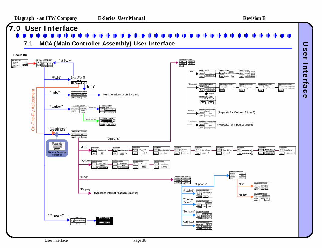
7.0 User Interface
7.1 MCA (Main Controller Assembly) User Interface
Power-Up
“RUN”
“STOP”
“Info”“Info”
“Label” “Test Print”
“Recall Format”
“Settings”
“Power”
“Options”
(Repeats for Outputs 2 thru 6)
(Repeats for Inputs 2 thru 4)
“RFID”
“Ethernet”
“Discrete Out”
“Discrete In”
“Home”
“Job”
“System”
Multiple Information Screens
“Diag”
“Rewind”
“Printer/ Drive”
“Sensors”
“Applicator”
“Options”
“Display”(Accesses internal Panasonic menus)
“I/O”
“RFID”
X
Optional Passcode Protection
On-
The
-Fly
Adj
ustm
ent
User Interface Page 38

Diagraph - an ITW Company E-Series User ManualU
ser InterfaceRevision E
7.2 Warning, Error, and Diagnostic Codes
WarningsWarnings are displayed to indicate that there is a temporary situation that may requireoperator intervention. These warnings to not stop machine operation. Some warningswill clear on the next successful attempt, while others require an offline pause to clear.
ErrorsErrors are displayed on individual screens to show possible causes for the error. Anerror will stop labeler operation, and illuminate the red segment of the warning tower,if present.
Motor Control Module CodesThese codes are displayed on the 2-digit display of the MCM during operation
Warning on Display MeaningAll Ok Labeler operation normal; no warnings or errors
Ribbon Low (W01) Printer reports ribbon low
Label Low (W02) Labeler reports label low through optional Label Low sensor
No Format (W03) Labeler wishes to print a label but no format is loaded in printer. Sendformat to the printer to continue operation
RFID Tag Bad (W04) Labeler has detected a bad RFID tag during encoding process
RFID Verify Error (W05) Labeler could not verify encoded tag information once applied to product
Serial Cmd Error (W06) Labeler received data that did not match any known commands
Timing Violation (W07) Labeler received a product detection trigger but could not start timingsequence, since the apply cycle was not complete. On a FASA system,this could mean that the second apply cycle has a product delay that istoo short.
Label on Detector 1 Labeler is waiting for Product Detector 1 to trigger before printing the nextlabel
Label on Detector 2 Labeler is waiting for Product Detector 2 to trigger before printing the nextlabel
Retract Sensor (W08) The labeler detected the optional auto-retract sensor was covered duringthe extension cycle, prior to product contact. This could indicate a labelfed beyond the pad, and covered the auto-retract sensor, thus forcing thelabeler to return from time-out only.
Message line for Warnings
Screen Screen ScreenE01 - Printer E02 - Repeat Print Cycle E03 - Repeat Tamp Cycle
E04 - Cylinder Not Home E05 - Ribbon Supply Out E06 - Motor Control Module
E07 - Rewind Tension E08 - Label Supply Out E09 - Second Apply Error
E10 - External Input
2-Digit Display Meaning8’8’ Power-up LED check
Pb Push button is stuck on
Ur..... XX Version (Vr) followed by 2-digit firmware version
E1 Error - Motor controller overcurrent, undervoltage, hall sensor error upon actuator return
E2 Error - Movement time-out. Actuator did not return home after 15 seconds
E3 Error - Motor controller driver damaged, hall sensors not connected or intermittent, power source error check at time of power-up
Eh or Pulsing Eh Error - MCA is in E-Stop, so MCM is paused and locked out from movement
t......... tc Tamping, then as movement begins, the c appears to indicate a compensation measurement
r...........rh Retracting, then as the actuator reaches home, the h appears to indicate the actuator is now home
User Interface Page 39
Diagraph - an ITW Company E-Series User ManualE
lectrical InterfacingRevision E
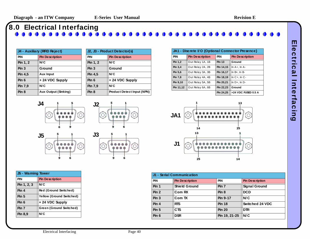
8.0 Electrical Interfacing
J1
JA1
J2
J3
J4
J5
J5 - Warning TowerPIN Pin Description
Pin 1, 2, 3 N/C
Pin 4 Red (Ground Switched)
Pin 5 Yellow (Ground Switched)
Pin 6 + 24 VDC SupplyPin 7 Green (Ground Switched)
Pin 8,9 N/C
J2, J3 - Product Detector(s)PIN Pin Description
Pin 1, 2 N/C
Pin 3 GroundPin 4,5 N/C
Pin 6 + 24 VDC SupplyPin 7,9 N/C
Pin 8 Product Detect Input (NPN)
J4 - Auxiliary (RFID Reject)PIN Pin Description
Pin 1, 2 N/C
Pin 3 GroundPin 4,5 Aux Input
Pin 6 + 24 VDC SupplyPin 7,9 N/C
Pin 8 Aux Output (Sinking)
J1 - Serial CommunicationPIN Pin Description PIN Pin Description
Pin 1 Shield Ground Pin 7 Signal GroundPin 2 Com RX Pin 8 DCDPin 3 Com TX Pin 9-17 N/CPin 4 RTS Pin 18 Switched 24 VDCPin 5 CTS Pin 20 DTRPin 6 DSR Pin 19, 21-25 N/C
JA1 - Discrete I/O {Optional Connector Presence}PIN Pin Description PIN Pin DescriptionPin 1,2 Out Relay 1A, 1B Pin 13 Ground
Pin 3,4 Out Relay 2A, 2B Pin 14,15 In A+, In A-
Pin 5,6 Out Relay 3A, 3B Pin 16,17 In B+, In B-
Pin 7,8 Out Relay 4A, 4B Pin 18,19 In C+, In C-
Pin 9,10 Out Relay 5A, 5B Pin 20,21 In D+, In D-
Pin 11,12 Out Relay 6A, 6B Pin 22,23 Ground
Pin 24,25 +24 VDC FUSED 0.5 A
Electrical Interfacing Page 40

Diagraph - an ITW Company E-Series User ManualM
aintenance Schedule
Revision E
9.0 Maintenance Schedule
These are average maintenance and repair/replace periods. Applications running higher throughputs will require attention more often.
Area Daily Monthly Two Years Description
Clean Printer Feed Rollers √ Use isopropyl alcohol and soft lint-free cloth to wipe alladhesive and paper dust free.
Replace Printer Feed Rollers √ Follow printer manufacturer’s procedures.
Replace Printer Peel Blade √ Follow printer manufacturer’s procedures.
Clean Label Present and Auto-Retract Sensors(if installed)
√ Use isopropyl alcohol and soft lint-free cloth to wipe alldust and contaminants free.
Clean Label Low Sensor (if present) √ Use isopropyl alcohol and soft lint-free cloth to wipe alldust and contaminants free.
Clean Product Detector Sensor(s) √ Use a soft lint-free cloth to wipe all dust and contaminantsfree. Be careful not to damage the plastic lens withalcohol-based solvents.
Inspect Rewind Belt √ Check for frayed edges and exposed reinforcement fibers.
Replace Rewind Belt √ Remove Rewind disk by taking off E-clip. Keep belt looseby holding up on the spring-loaded belt tensioner. Replacebelt and reinstall the Rewind disk.
Replace Unwind Dancer Spring √ Unwind spring can be accessed through the slots of theUnwind disk.
Clean Tamp Pad √ Use compressed air and a hard bristle brush to clean anycontaminants in the pad face. Isopropyl alcohol can beused to wipe the pad clean. DO NOT SPRAY CHEMICALS INTO THE VACUUM FAN!
Clean Actuator Rod √ Clean the actuator rod with a cleaning cloth. Use a lightamount of isopropyl alcohol on cloth to remove build-ups.DO NOT USE OIL OR GREASE ON ACTUATOR ROD!
Inspect Actuator Drive Belt √ Check for frayed edges and exposed reinforcement fibers.
Replace Actuator Drive Belt and Bearing Pads √ Follow replacement procedures contained with newcomponents.
Clean Baseplate Spindle(s) √ Use isopropyl alcohol and soft lint-free cloth to wipe alldust and contaminants free.
Replace Baseplate Spindle(s) √ Replace by unscrewing the old spindle and replace withnew spindle and some service-removable Loc-tite.
Maintenance Schedule Page 41

Diagraph - an ITW Company E-Series User ManualD
iagnosticsRevision E
10.0 Diagnostics
OverviewThe Diagraph labeler employs a built-in diagnostic testing system to allow mostproblems to be identified and corrected without need for more sophisticated testequipment. This is an inherent characteristic of the PA/4600E and PA/6000E labelers,and should be used to save time and efforts. The sections below list the capabilitiesand how to access them.
Heartbeat LightAs simple as this indicator is, it can help identify a problemwith the circuit boards in the labeler. All boards that containfirmware have a flashing blue LED light that indicates anormal, working module. The MCA, Ethernet Module, andMCM contain this heartbeat indicator.
Won’t PrintWhen a labeler is placed online, there are reasons that maynot seem apparent for why the label doesn’t immediatelyfeed out. First basic checks should include mode selections,like Demand Mode printing or Apply Mode is set to Wipe.Next verify a print batch is present in the print engine, andthe engine is online. If all of these check out, the next stepsshould be to pair-down the possible causes to find the culprit.Use the Diagnostic menu in the MCA to force a print. Thisdirectly activates the print signal to the print engine. Visibleon the Interface Board of the MCA (p/n:4600-350) is theyellow PRT_STRT signal LED. When this toggles, the printershould start printing and when finished, the green PRT_ENDsignal LED should momentarily flash. If not, the problem islocated outside of the MCA, possibly the applicator cable orprinter.
Won’t ApplyThere are various reasons why a labeler will not apply a label. Most of these arejustified due to the settings or the state of the labeler. The MCA display will showstatus like Timing Violation, Label on Detector 1, Label on Detector 2, and Cylinder NotHome. Situations that lead to missed application can be caused by formats sent to the printertoo late for application or the label is missing from the pad just prior to the applicationtime. These two events will likely cause a Timing Violation warning on the display.Failure modes leading to missed or no application can be narrowed to the productdetection trigger (input) and the extension of the actuator signal (output). The Product
Trigger can be viewed on the green LED inside the MCA MCU Board (D9, PDET_1). Itcan also be viewed on the Diagnostic screen of the MCA display in the Sensorsscreen. Likewise, the output for “Tamp” can be viewed on the MCA Interface Boardyellow LED (D9, TAMP). The Diagnostic menu allows for the Tamp signal to beexercised.
Electric Actuator TestThe E-Series actuator can be tested off-system or on-system, but independent of the MCA. This is done bypressing and holding the Set button on the MCM while turning power on. The displaywill initially show “Pb”, indicating a stuck push button. Release the Set button, and thedisplay will show “dG” for diagnostics. The Set button can now be pressed to extendthe actuator. The power must be cycled to exit the diagnostic mode.There are diagnostic LED’s dedicated to showing the actuator operation internal to theMCM. These are noted in the image below:
The LED’s for Air Assist and Vacuum Fan will show a slight flicker since they aremodulated to control speed. Most visible will be the Vacuum Fan LED, which will flickermore noticeable at the lower settings of the “F” fan speed on the MCM. When a label ison the tamp pad, the Vacuum Fan spins up to the set speed. After a label has been onthe pad, and then take away without a new label taking it’s place, the fan will slowdown to an idle speed after 5 seconds. The flicker rate of the LED will show thisdifference in speeds between label in place and removed.
Flashes every 0.25 inchesof actuator travel
Indicates actuator is Home 24 VDC PWR
5 VDC PWR
Air Assist Module PWM
Vacuum Fan PWM
MCMMCM MCMMCM
MCA
MCMMCM
MCA
Diagnostics Page 42

Diagraph - an ITW Company E-Series User ManualInterconnection D
iagramRevision E
11.0 Interconnection Diagram
Interface Board 4600-350
MCA Board 4600-300
Discrete I/O * 6145-400
Ethernet Module *6000-400
Print Engine(SATO)(Zebra)
RS23
2
App
licat
or
J7 J8
SATO: 4600-504Zebra: 6000-504
SATO: 4600-505Zebra: 6000-505
Serial Cable
Interface Cable
Label Present *6000-903
Actuator Home
Auto-Retract *6000-903
J9
J10
J11
J6
4600
-502
User Interface
J5
MCM Board6000-350
J4
J10.A
Power Supply
4600-522
J3
Label Low * 6000-903J2
J1Rewind Motor
4600-503
Port
Actuator Motor
4600-503J6J5
J7
J4Vacuum Fan
6000-507
Air Assist Fan
6000-666J1
J7
JA1J1
PC or Similar *
Serial Cable
PLC or Similar *
J5 J3 J2
E-Stop SW14600-501
2806-478
Product Detect 6000-900 : Diffuse Light6000-901 : Break Beam6000-902 : Laser
Product Detect * 6000-900 : Diffuse Light6000-901 : Break Beam6000-902 : Laser
Primary Sensor
Special Purpose Sensor
Warning Tower * 6150-828
4600-906
6000-509 Home Sensor Interface Cable
6000-510E-Tamp Control Cable
6000-512
AC Power to MCAPower Supply
Print Engine AC
MCM Power
AC Power
* = Denotes Optional Equipment
Interconnection Diagram Page 43

Diagraph - an ITW Company E-Series User ManualS
pare Parts List
Revision E
12.0 Spare Parts List - System
Part NumberRecm’d. Spare Part
ApplyModule Description
DOCUMENTATION6000-010 ALL PA/4600E and PA/6000E User Manual
PA/4600E and PA/6000E4600-522 ALL MCA Power Supply (Auto-Ranging, 24 VDC
Output)
4600-511 ALL AC Power Cord
4600-643 ALL Unwind Dancer Arm Spindle
4600-200 ALL MCA User Interface Touch Screen LCD
4600-951 √ ALL Main MCU PCB Assembly
4600-500 ALL Main Controller Assembly III (MCA III)Includes: MCU Board, Interface Board, UserInterface, Enclosure
6000-350T √ E-TAMP MCM Motor Controller PCB Assembly
6000-350F √ E-FASA MCM Motor Controller PCB Assembly
6000-550 ALL MCM AssemblyIncludes: MCM Motor Controller PCB, PowerSupply, Enclosure
4600-503 ALL Rewind BLDC Motor
4600-647 ALL Rewind Clasp
4600-950 √ ALL MAINTENANCE KIT:Wear Items SetIncludes: (2) Rewind Belts, (3) Spindles, (2/ea.)Springs, (3) Unwind Fins, (3) Web guides
6000-950 √ E-TAMP E-TAMP MAINTENANCE KIT:Wear Items SetIncludes: Actuator Belts, Bearing Pads, IdlerRollers, Belt Clamp, Bumper, Springs, Motor DustCap
6000-951 √ E-FASA E-FASA MAINTENANCE KIT:Wear Items SetIncludes: Motor Drive Belt, Swing Arm Belt, ShockAbsorber Bumper, Cable Ties, Springs, UHMW
6000-952 √ E-WASA E-WASA MAINTENANCE KIT:Wear Items SetIncludes: Springs, UHMW Rollers, Fan Assembly, Nylon Brushes
6000-620x10 E-TAMP E-TAMP Actuator Module, 10 inch stroke
6000-620x20 E-TAMP E-TAMP Actuator Module, 20 inch stroke
6000700x10 E-FASA 10 inch E-FASA Actuator Assembly ONLY - SideApply (no MCM)
6000700x10ND E-FASA 10 inch E-FASA Actuator Assembly ONLY - NoseUp/Down (no MCM)
6000700x20 E-FASA 20 inch E-FASA Actuator Assembly ONLY - SideApply (no MCM)
6000700x20ND E-FASA 20 inch E-FASA Actuator Assembly ONLY - NoseUp/Down (no MCM)
6000-666 √ ALL Air Assist Module
6000-516 √ ALL Vacuum Fan Assy.
4600-900 ALL Product Detector - Diffused Light
OPTIONS6000-828 ALL LED Warning Tower Assembly
6145-405 ALL Discrete I/O Board (Optional Device)
6000-903 √ ALL Auto-Retract, Label low, or Label Present Sensorand PUR cable (1 sensor/cable/cover per kit)
Part NumberRecm’d. Spare Part
ApplyModule Description
Spare Parts List - System Page 44

Diagraph - an ITW Company E-Series User ManualS
pare Parts List
Revision E
13.0 Spare Parts List - Print Engines
Part NumberRecm’d. Spare Part
Description
SATO SE Print Engine Components7500-020 SATO Platen Assy PR0730100
2801-451 SATO Bearing (Inner)
2850-999 SATO Bearing / Ball Supporter (Outer) PT1109050
2803-992 SATO Timing Belt PT8150064
7500-050 SATO Timing Belt PT8190064
6150-856 SATO Timing Belt PT8085048
2806-253 √ SATO 203 dpi Printhead GH000781A
2804-637 SATO Platen Roller Pulley PE8730200
R00017020 SATO Pressure Roller Assembly R00017020
6152-117 SATO Platen Roller PR0730100
SATO Lt408 Print Module Components4600-800 SATO Lt 408 Print Engine (Entire Printer)
4600-810 √ SATO Lt 408 Print Head
4600-811 SATO Lt 408 Platen Roller Assy
4600-812 SATO Lt 408 Feed Roller Assy
4600-813 SATO Lt 408 Ribbon Roller Assy
4600-814 SATO Lt 408 Gap Sensor Assy.
4600-815 SATO Lt 408 Main PCB
4600-816 SATO Lt 408 Motor Drive PCB
4600-817 SATO Lt 408 Power Supply
4600-819 SATO Lt 408 Timing Belt 218mm (Ribbon Drive)
4600-820 SATO Lt 408 Timing Belt 260mm (Stepper Main)
4600-821 SATO Lt 408 Timing Belt 186mm (Platen Drive)
4600-822 SATO Lt 408 Ribbon Sensor
4600-823 SATO Lt 408 Torque Limiter (ribbon take-up)
4600-824 SATO Lt 408 Torque Limiter (ribbon supply)
4600-825 SATO Lt 408 Roller bearing (all rollers)
SATO 84xx Se Engines6000-6152094 Engine Assembly, Sato 8485SE
6000-6152092 Engine Assembly, Sato 8490SE
6000-6152091 Engine Assembly, Sato 8460SE
Zebra PAX Engines6000-6153091 Engine Assembly, Zebra 112 PAX4
6000-6153092 Engine Assembly, Zebra 113 PAX4
6000-6153089 Engine Assembly, Zebra 172 PAX4
6000-6153090 Engine Assembly, Zebra 173 PAX4
Part NumberRecm’d. Spare Part
Description
Spare Parts List - Print Engines Page 45

Diagraph - an ITW Company E-Series User ManualS
ystem D
rawings
Revision E
14.0 System Drawings
System Drawings Page 46

Diagraph - an ITW Company E-Series User ManualS
ystem D
rawings
Revision E
14.1 System Drawings - E-TAMP Actuator
System Drawings Page 47

Diagraph - an ITW Company E-Series User ManualS
ystem D
rawings
Revision E
14.2 System Drawings - E-FASA Actuator
0 Degrees Mount (Side Apply) 90 Degrees Mount (Nose-Up/Nose-Down)
System Drawings Page 48

Diagraph - an ITW Company E-Series User ManualS
ystem D
rawings
Revision E
14.3 System Drawings - E-WASA
System Drawings Page 49

Diagraph - an ITW Company E-Series User ManualS
ystem D
rawings
Revision E
System Drawings Page 50

Diagraph - an ITW Company E-Series User ManualS
ystem D
rawings
Revision E
System Drawings Page 51

Diagraph - an ITW Company E-Series User ManualS
ystem D
rawings
Revision E
14.4 System Drawings - E-Series Components
System Drawings Page 52

Diagraph - an ITW Company E-Series User ManualS
ystem D
rawings
Revision E
14.5 System Drawings - Optional “Chi” Stand
System Drawings Page 53

Diagraph - an ITW Company E-Series User ManualD
eclaration of Conform
ityRevision E
15.0 Declaration of Conformity
DECLARATION OF CONFORMITY
Standards:• Conducted Emissions (EN55 011)• Harmonics (EN 61000-3-2)• Flicker (EN 61000-3-3)• Radiated Emissions (EN55 011)• Electrostatic Discharge (ESD) (EN 61000-4-2)• Radiated Immunity (EN 61000-4-3)• Fast Transient Burst (EN 61000-4-4)• Surges (EN 61000-4-5)• Conducted Immunity (EN 61000-4-6)• Power Frequency Magnetic Field (EN 61000-4-8)• Voltage Dips and Interrupts (EN 61000-4-11)• Information Technology (EN60950-1:2001)
Diagraph, an ITW Company, hereby declares that the equipment specified below has been tested and found compliant to the following directives and standards-
Directives:• EMC 89/336/ECC• Low Voltage 73/23/EEC
Equipment Type:Printer / Applicator
Model Number:PA/4600E and PA/6000E
Bruce CastroQuality/Safety ManagerDiagraph, an ITW Company1 Missouri Research Park Dr.St. Charles, MO 63304USA
Declaration of Conformity Page 54