e series (page 1) - hardwarechimp.com · ed225 hole tap for 1 5⁄ 32" mortise cylinder tap...
TRANSCRIPT

MORTISE AND RIM CYLINDERS
CY
LIN
DER
S

1E Mortise CylinderStandard mortise applications require use of BEST’s 1E Series cylinders with standard 1E-C4 cam.BEST cylinders may
be altered to function with other manufacturers' locks byuse of different cams (see page 8) and different cylinderrings (see page 9). Special cylinder variations are avail-able for most applications (see pages 4 & 5). BESTcylinders are machined from brass or bronze bar stock andare available in a variety of finishes. Additional security isprovided by a set screw that mounts diagonally in the cylinder wall and when tightened, holds the cylinder securely in the housing. BEST mortise cylinders feature theBEST interchangeable core and may be masterkeyed intoany existing BEST system. Contact your local Best AccessSystems sales office for information on special cylinder applications not listed in this catalog.
ECIFICATIOSpecifications
Cylinder Dimension DoorNomenclature “A” Thickness
1E-64 1 1⁄8" 1 5⁄8" to 2 1⁄4"1E-74 1 1⁄4" 1 7⁄8" to 2 1⁄2"
Cylinder diameter - 1 5⁄32"To order: see below example: 1E74-C4-RP3-626Products covered by on or more of the following patents:4,437,695 4,633,690 4,616,394
2 MORTISE AND
“A”
TABLE OF CONTENTS Page Page1E Series Features ................................................................2 Eurocylinders ..........................................................71E Series Specs/How to Order ..............................................2 Cylinders and Cams ................................................81E Series Rings/Spindles/Mortise Service Equipment ..........3 1E Cylinder Special Rings ......................................91E Series Special Cylinders ..............................................4, 5 5E Series Specs/Accessories ................................101E7J4/1E7K4 High Security Cylinders ..................................6 5E Series How to Order ........................................11Patented Keying ....................................................................6
“A”
1E SERIES FEATURES
STEP A B C D E F G H
1E 7 4 C4 RP3 626 **Cylinder Core Function Standard Cam or Rings Standard OptionsDiameter Housing Code Mortise Spindle Finishes
Length Code
1E– 1 5⁄32" 0– dummy 2– rim Blank– standard C4– standard cam RP1– tapered cyl. 605 606 MC– marine 3E– 1 1⁄2" 6– 6 pin 4– mortise* 22– 1 3⁄8" C181– Adams Rite RP2– 6 pin mortise 612 613 construction5E– see 7– 7 pin 6– tapered 24– 1 1⁄2" up to MS cam RP3– std. package 622 625pages 10-11 housing mortise 96– 6" S2– standard RP4– 3E mortise 626 6908E– see accepts spindlepage 7 all Best
cores
* For additional special mortise cylinders, see pages 4 and 5.** Must specify keymark and number of keys or designate L/C for less core.
Specifications
Cylinder Dimension DoorNomenclature “A” Thickness
1E-62 1 3⁄16" 1" to 2 3⁄4"1E-72 1 11⁄32" 1 1⁄4" to 3"
Cylinder diameter– 1 5⁄32"To order: see below example: 1E72-S2-RP3-626
HOW TO ORDER
1E S
ER
IES
HO
W T
O O
RD
ER
1E Rim CylinderStandard rim cylinder applications require the use of BEST’s1E rim cylinder series. BEST rim cylinders are interchangeablewith other manufacturers’ rim cylinders. BEST rim cylindersare machined from solid bar stock and are available in a variety of finishes. The standard package for the BEST rimcylinder includes cylinder, RP3 ring package, 1E-S2 spindle,clamp plate and clamp plate screws. BEST rim cylinders feature the BEST interchangeable core and may be master-keyed into any existing Best system.
see pages 4-5for special cylinders (see page 4-5)
(For special camssee page 8)
(For special rings see page 9)
Specify handif required

STANDARD CAMStandard Cam for 1E-64, and
1E-74 Mortise Cylinders
Unless otherwise specified, the 1E-C4 cam is supplied on all 1E mortise cylinders.
Commonly used cams are listed on page 8.
If a cam other than the variety listed is needed, a samplecam should be forwarded to your local BEST office alongwith the lock manufacturer’s name and lock series or identification number.
RP Standard Ring PackageThe RP standard ring package includes a 1E-R3 ( 3⁄16" ) and 1E-R5 ( 3⁄8" ) ring.
RP1 Ring PackageThe RP1 ring package for the 1E-76 cylinder includes a 1E-R2 (1⁄8" ) and 1E-R3 ( 3⁄16" ) ring.
RP2 Ring PackageThe RP2 ring package for the 1E-64 cylinder includes a 1E-R2 (1⁄8" ) and 1E-R4 (1⁄4" ) ring.
RP3 Ring PackageThe RP3 ring package for the 1E-62, 1E-72 and 1E-74 cylindersincludes a 1E-R2 (1⁄8" ) and a 1E-R5 ( 3⁄8" )
3 RIM CYLINDERS
STANDARD RINGS
1E-R53⁄8"
1E-R21⁄8"
1E-R21⁄8"
1E-R41⁄4"
1E-R33⁄16"
1E-R33⁄16"
STA
ND
AR
D C
AM
SP
IND
LES
1E-R53⁄8"
1E-R21⁄8"
SPINDLES
Standard1E-C4 Cam
1E-S2 Spindle (Steel) - A-40100-SH1E-S3 Spindle (Bronze) - A-40100-Z5" Spindle - A-54950; 5⁄32" Spindle - A-40101
The 1E-S2 flat spindle is supplied standard on all 1E rimcylinders. If marine application is necessary, request “marine construction” (1E-S3 bronze spindle and nonferrous materials supplied). A five (5) inch spindle is available for thick door applications.
MORTISE SERVICE EQUIPMENT
ED211 Mortise Cylinder WrenchThe Best mortise cylinder wrench and test handle is an essential dual-purpose tool. The double end is used primarilyto install or remove BEST mortise cylinders without marring the cylinder surface finish. The single end may be used to test the lock operation, as well as align the throw pins.To order specify: ED211 mortise cylinder wrench.
ED212 Mortise Cylinder Cam Assembly ToolMortise cylinder cams are quickly changed with the use of this tool. Approximate length 1 3⁄4". To order specify: ED212 assembly tool.
ED221 Mortise Cylinder Thread Repair DieTool for re-threading 1 5⁄32" diameter cylinders.To order specify: ED221 thread repair die.
ED222 Cylinder Cam Testing ToolSpecial cylinder / wrench assembly. Screws provide rapid means to install cams for testing.To order specify: ED222 cam testing tool.
ED225 Hole Tap For 1 5⁄32" Mortise CylinderTap tool used to re-thread housing threads for 1E Mortise Cylinders.
A40095 Standard Throw Pins
ED211
ED212
SP
IND
LES

SPECIAL CYLINDERSSpecial Length Mortise Cylinders Specifications
Diameter: 1 5⁄32"Uses: Special thickness doorsLength: See chartMaterial: Solid brass or bronzeCam: Standard 1E-C4 cam (see page 2)
supplied unless otherwise specified.Rings: The RP2 (for 6 pin) and RP3
(for 7 pin) package are supplied standard (page 2) unless otherwise specified.
To order: Designate desired length from chart under length code step “D” as shown (page 2).
Example: 1E-74-32
Taper Head Mortise Cylinder SpecificationsDiameter: 1 5⁄32"Length: 6 pin – 23/32" ; 7 pin – 3⁄4"Door thickness: 6 pin- 1 3⁄8" to
1 3⁄4" (including trim)7 pin– 1 3⁄8" (including trim)7 pin– 1 3⁄4" (without trim)
Material: Solid brass or bronzeCam: Standard 1E-C4 cam
supplied unless otherwise specified.Rings: The RP1 ring package (page 2) is supplied
standard with all 1E taper cylinders (page 2). To order: See page 2. Example: 1E-76-C181-626
Turn Knob Cylinders SpecificationsDiameter: 1 5⁄32"Length: Mortise- 6 pin–1 1⁄8" ; 1E6A4
Mortise- 7 pin–1 1⁄4" - 1E7A4Rim- 6 pin–1 3⁄16" - 1E6A2Rim- 7 pin–1 11⁄16" - 1E7A2
Material: Solid brass or bronzeCam: Standard 1E-C140 cam
supplied unless otherwise specified (see page 2).Rings: Ring packages are supplied standard as follows
(unless otherwise specified): Mortise 6 pin: RP2 ring package (see page 2)
Mortise 7 pin: RP3 ring package (see page 2) Rim 6 and 7 pin: RP3 ring package (see page 2)
To order: Designate “A4” on step “C” of order procedure (page 2). Example: 1E-7A4-C140-RP3-626 R-function turn knob cylinders, RH-1ESPL-7-B35401, LH-1ESPL-7-B35405 Special length cylinders 1.5"-1ESPL-7-A20336 1.75"-1ESPL-7- A20337, 2"- 1ESPL-7-B23409
Note: These should not be used in conjunction with deadbolt function BEST mortise locks.
1 1⁄2" Diameter Mortise Cylinder SpecificationsDiameter: 1 1⁄2"Length: 6 pin–1 1⁄8" ; 7 pin–1 1⁄4"Door thickness:
6 pin–1 5⁄8" to 2 1⁄4" (includes trim) 7 pin–1 7⁄8" to 2 1⁄2"
Material: Solid brass or bronzeCam: Standard 3E-C3 cam supplied
unless otherwise specified.Rings: The RP4 ring package is
supplied with 3E cylinders. This package includes a 3E-R2 ( 1⁄8" ) and a 3E-R4 ( 1⁄4" ) ring.
To order: Designate “3E” on step “A” of order procedure (page 2) Example: 3E-74-C3-RP4-626
Options: 3E-04-Dummy, 3E-7A4-Turn knob, 3E-7B4-Dust Cover. Adaptor ring to allow 1E74 cylinders to fit a 3E tapped hole - A26139.
Dummy Mortise and Rim Cylinders SpecificationsDiameter: 1 5⁄32"Length: Mortise –1 1⁄8" ; Rim –1 1⁄8"Material: Solid brass or bronzeRings: Ring packages are supplied standard as
follows: Mortise: RP2 ring package(see page 2) Rim: RP3 ring package (see page 3)
To order: Designate “0” on step “B” of order proce-dure (page 2) Example: 1E-02,1E04-slot in back-1ESPL-6-B4619 1E04-slot in back-1ESPL-7-B4620, 1E02-slot in face-1ESPL-6-A5035, Special 1E04 with slot on back- 1ESPL-7-B4620. Special length 1E04 cylinders: 1 1⁄2" – 1ESPL-7-A9619 1 3⁄4" – 1ESPL-7-A20331
* Reference to Length "A" on Mortise Cylinder Length Chart.
4 MORTISE AND
“A”*
1E76
1E7A4
1E74
“A”*
1E S
ER
IES
“A”*3E74
1E04 1E02
Length Designate this number"A" on step “D”of order
procedure (page 2)
1 3⁄8" 221 1⁄2" 241 5⁄8" 261 3⁄4" 281 7⁄8" 302" 32
2 1⁄8" 342 1⁄4" 362 1⁄2" 402 3⁄4" 443" 48
3 1⁄2" 564" 64
4 1⁄2" 725" 80
5 1⁄4" 886" 96
Mortise Cylinder Length Chart
Riv
eted
cam
sS
crew
-on
cam
s

Mortise and Rim Cylinders with Dust Covers SpecificationsDiameter: 1 5⁄32"Length: Mortise- 6 pin– 1 1⁄8" ; 7 pin– 1 9⁄32"
Rim- 6 pin– 1 3⁄16" ; 7 pin– 1 11⁄32"Material: Solid brass or bronzeCam: Standard 1E-C4 cam
(see page 4) 1E series supplied unless otherwise specified.
Rings: Ring packages are supplied standard as follows (unlessotherwise specified): Mortise 6 pin:RP2 ring package (see page 2), Mortise 7 pin: RP3 ring package (see page 2)Rim 6 and 7 pin: RP3 ring package (see page 2)
To order: Designate “B4” on step “C” of order procedure (page 2). Example: 1E-7B4-C4-RP3-626
Mortise Cylinder Direct Motion Cam SpecificationsDiameter: 1 5⁄32", slabbed, threaded to the headLength: 6 pin–1 5⁄16" ; 7 pin–1 15⁄32" From head to camMaterial: Solid brass or bronzeCam: C228 - cabinet cylinder
cam standard. Cam prevents key from being withdrawn in unlocked position.
Rings: The RP2 ring package is supplied standard for 6-pin and 7-pin unless otherwise specified (page 2)
To order: Designate “D4” on step “C” of order procedure(page 2). Example: 1E-7D4-C228-RP3-626To order with a utility cam lengths from 5⁄8" - 3 1⁄2"1 3⁄4"- cylinder length (RH) 1ESPL-7-A10623 x C228
(LH) 1ESPL-7-A10624 x C2282 3⁄4"- cylinder length (RH) 1ESPL-7-A8774 x C228
Standard Mortise Cylinder Lost Motion Cam SpecificationsDiameter: 1 5⁄32"Length: 6 pin–1 1⁄8"; 7 pin–1 1⁄4"Material: Solid brass or bronzeCam: 1E-C230 - cam supplied
standard 1E-C230 is cam 1E-C4(page 2) set up for lost motion. Specify cylinder handing as for hand and side of door.
Examples: RHO (Right Hand Outside); RHI (Right Hand Inside); LHO (Left Hand Outside); LHI (Left Hand Inside).
Rings: The RP2 ring package is supplied standard for 6-pin and 7-pin unless otherwise specified (page 2)
To order: Designate “F4” on step “C” of order procedure (page 2). Example:1E-7F4-C230-RP3-626-RHO
5 RIM CYLINDERS
1E7D4
1E7G4
1E7B4
1E S
ER
IESSPECIAL CYLINDERS
1E7C4
Square Head Mortise Cylinder-Wrench Resistant Foruse in Narrow Stile Doors Specificatons
Diameter: 1 5⁄32"Length: 6 pin–1 1⁄4" ; 7 pin–1 13⁄32"Material: Solid brass or bronzeCam: As specified on order
(see page 8 for cams available)Rings: Package includes special
5⁄8" slip ring To order: Designate “C4” on step
“C” of order procedure (page 2) Example: 1E-7C4-C181-R1010 (5⁄8" length)- 626
Other length rings are available.
Slabbed Cabinet Mortise Cylinder Lost Motion Cam Specifications
Diameter: 1 5⁄32"Length: 6 pin–1 1⁄8" (effective length)
7 pin–1 1⁄4" (effective length) Material: Solid brass or
bronze Cam: C229- cam
supplied unless otherwise specified (1E-C229, when ordered separate from unit). Specify hand: RH or LH
Rings: The RP2 ring package is supplied standard for 6 and 7-pin unless otherwise specified (page 2)
To order: Designate “E4” on step “C” of order procedure (page 2).
Example: 1E-7E4-C228-RP3-626-RHSpecial Length:
2" cylinder length (11⁄4" effective length) RH-1ESPL-7A-9580; LH-1ESPL-7-A9577
2 1⁄4" cylinder length (2" effective length)RH-1ESPL-7-A8813; LH-1ESPL-7-A8812
Hotel/Motel Mortise Cylinder Shifting Cam SpecificationsDiameter: 1 5⁄32"Length: Mortise 6 pin–1 5⁄16" ; 7 pin–115⁄32"Material: Solid brass or bronzeCam: C258 or cam supplied as
specified (see page 8) Rings: The RP2 ring package is
supplied standard for 6-pin and 7-pin unless otherwise specified (page 2)
To order: Designate “G4” on step “C” of order procedure (page 2).
Example: 1E-7G4-C258-RP3-626
1E7F4
1E7E4
6 MORTISE AND
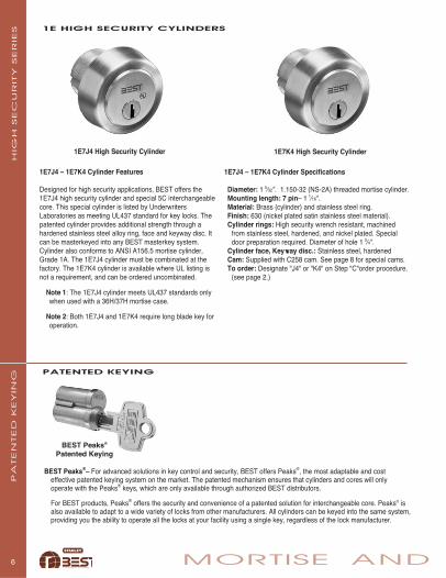
1E7K4 High Security Cylinder
1E7J4 – 1E7K4 Cylinder Features
Designed for high security applications, BEST offers the1E7J4 high security cylinder and special 5C interchangeablecore. This special cylinder is listed by UnderwritersLaboratories as meeting UL437 standard for key locks. Thepatented cylinder provides additional strength through ahardened stainless steel alloy ring, face and keyway disc. Itcan be masterkeyed into any BEST masterkey system. Cylinder also conforms to ANSI A156.5 mortise cylinder,Grade 1A. The 1E7J4 cylinder must be combinated at thefactory. The 1E7K4 cylinder is available where UL listing isnot a requirement, and can be ordered uncombinated.
Note 1: The 1E7J4 cylinder meets UL437 standards onlywhen used with a 36H/37H mortise case.
Note 2: Both 1E7J4 and 1E7K4 require long blade key for operation.
1E7J4 High Security Cylinder
1E7J4 – 1E7K4 Cylinder Specifications
Diameter: 1 5⁄32". 1.150-32 (NS-2A) threaded mortise cylinder. Mounting length: 7 pin– 1 1⁄16".Material: Brass (cylinder) and stainless steel ring.Finish: 630 (nickel plated satin stainless steel material).Cylinder rings: High security wrench resistant, machined
from stainless steel, hardened, and nickel plated. Special door preparation required. Diameter of hole 1 3⁄4".
Cylinder face, Keyway disc.: Stainless steel, hardenedCam: Supplied with C258 cam. See page 8 for special cams. To order: Designate "J4" or "K4" on Step "C"order procedure.
(see page 2.)
HIG
H S
EC
UR
ITY
SER
IES 1E HIGH SECURITY CYLINDERS
PATENTED KEYING
PA
TEN
TED
KEY
ING
BEST Peaks®
Patented Keying
BEST Peaks®– For advanced solutions in key control and security, BEST offers Peaks®, the most adaptable and cost effective patented keying system on the market. The patented mechanism ensures that cylinders and cores will only operate with the Peaks® keys, which are only available through authorized BEST distributors.
For BEST products, Peaks® offers the security and convenience of a patented solution for interchangeable core. Peaks® is also available to adapt to a wide variety of locks from other manufacturers. All cylinders can be keyed into the same system,providing you the ability to operate all the locks at your facility using a single key, regardless of the lock manufacturer.

7 RIM CYLINDERS
C
AB
AB
Flush Mount
RabbetedMount
CylinderRetaining
Screw
Rabbeted MountFront View
HOW TO ORDER: EUROPROFILE
3C– European Core
SPECIAL EUROPROFILES
Mortise locksets from a number of different international manufacturers can be incorporated into your BEST masterkeyedsystem by replacing the cylinder with a Best Eurocylinder and 3C European interchangeable core. When ordering, please specify the lock manufacturer’s name and their model number. Some Euro profile cylinders will accept Best standard core ratherthan the 3C core. Please specify the “E” option when ordering standard cores for use in Eurocylinders.
The most popular of the European adaptations is for the European cylinder. Best Access Systems order nomenclature and several required critical dimensions are listed below. Please specify, as requested when ordering.
Critical Dimensions - Europrofile“A”– Dimension to center of lockset case. Determined by
measuring from set screw location to outside of door face.“B”– Door thickness.“C”– Dimension from center of key rotation to center of handle
rotation, if other than 72mm. Maximum allowed– 114mm. Minimum allowed– 37mm
8E7E5– Europrofile*(* Requires use of 3C core)
8E7H6– for locks manufacturedin Germany
EU
RO
CY
LIN
DER
SEUROCYLINDERS
8E7E5 25mm 45mm 65mm Keyed Alike 619
Eurocylinder “A” Dimension “B” Dimension “C” Dimension Keying Finish: 619 - SatinInstructions Nickle Plated
626 - SatinChrome Plated

CYLINDERS AND CAMSSpecial cams are available which will operate most mortise locksets, regardless of make or function. With these cams,your masterkeyed system can be extended through the use of replacement cylinders with cams similar to those being used. A few of the cams are illustrated. Other designs are available upon request. All cams available are designed for use on BEST mortise cylinders.
WARNING– Best Access Systems desires to provide up-to-date and reliable product adaptation uses. However, BEST cannot guarantee the quality of other manufacturers' locksets. In addition, other lock manufacturers' may make changes to their product that affect the operation and compatibility of our core and cylinder adaptation. When this occurs, those manufacturers' have no obligation to notify BEST. If you are using a BEST cylinder in another manufacturers' lockset and find that it does not operate properly for anyreason, please contact your local BEST sales office immediately.
NOTE: Cams not drawn to scale
NOTE: While certain functions may require a different cam, in general the following cams will work for these common applications.
C4........Standard camC127....Arrow mortise (latch)C161....Corbin-Russwin mortise
Arrow mortise (deadbolt)C181....Adams Rite
8 MORTISE AND
.252
.624
.232
.730.764
.158
.735
.326
.784
.328
.715
.300.228
.703
C161(when ordered with cylinder,step E, page 2) 1E - C161
(for cam only)
C191(when ordered with cylinder,step E, page 2) 1E - C191
(for cam only)
C208(when ordered with cylinder,step E, page 2) 1E - C208
(for cam only)
C118(when ordered with cylinder,step E, page 2) 1E - C118
(for cam only)
.703
.300
C4(when ordered with cylinder,
step E, page 2) 1E - C4(for cam only)
C127(when ordered with cylinder,step E, page 2) 1E - C127
(for cam only)
C128(when ordered with cylinder,step E, page 2) 1E - C128
(for cam only)
C136(when ordered with cylinder,step E, page 2) 1E - C136
(for cam only)
.724
.326
C129(when ordered with cylinder,step E, page 2) 1E - C129
(for cam only)
C265(when ordered with cylinder,step E, page 2) 1E - C265
(for cam only)
C258(when ordered with cylinder,step E, page 2) 1E - C258
(for cam only)
C210(when ordered with cylinder,step E, page 2) 1E - C210
(for cam only)
C181(when ordered with cylinder,step E, page 2) 1E - C181
(for cam only)
.660
.300
.232
.720 .565
.184
.713
.183
CY
LIN
DER
S A
ND
CA
MS
C191....Best mortise (latch)C208....SargentC258....Best mortise (deadbolt)C265....Schlage L mortise

1E-R8 RING CHART
Overall Nomenclature NomenclatureLength if Ordered if Ordered
Available With Cylinder Without(see step “F” page 2) Cylinder
1⁄8" R802 1E-R8023⁄16" R803 1E-R8031⁄4" R804 1E-R8045⁄16" R805 1E-R8053⁄8" R806 1E-R8067⁄16" R807 1E-R8071⁄2" R808 1E-R8089⁄16" R809 1E-R8095⁄8" R810 1E-R81011⁄16" R811 1E-R8113⁄4" R812 1E-R812
13⁄16" R813 1E-R8137⁄8" R814 1E-R814
15⁄16" R815 1E-R8151" R816 1E-R816
9 RIM CYLINDERS
SPECIAL RINGS
Specifications - 1E-R7To be used with BEST 1E series (1 5⁄32" ) Cylinders.
Dimensions– inside diameter- 1 5⁄32", outside diameter 1 5⁄16" length-see chart at left.
Material– solid brass or bronzeFinish– available in 605, 606, 612, 613, 625 and 626
1E-R7 Straight Ring
1E S
ER
IES
Specifications - 1E-R8To be used with BEST 1E series (1 5⁄32" ) Cylinders.
Dimensions– inside diameter - 1 5⁄32", inside rim counter-bored to protect cylinder head. Outside diameter - tapered 1 1⁄2" to 1 29⁄64" length-see chart at left.
Material– solid brass or bronzeFinish– available in 605, 606, 612, 613, 625 and 626
1E-R8 Tapered Slip Ring-Wrench Resistant
1E-R7 RING CHART
Overall Nomenclature NomenclatureLength if Ordered if Ordered
Available With Cylinder Without(see step “F” page 2) Cylinder
1⁄8" R702 1E-R7023⁄16" R703 1E-R7031⁄4" R704 1E-R7045⁄16" R705 1E-R7053⁄8" R706 1E-R7067⁄16" R707 1E-R7071⁄2" R708 1E-R7089⁄16" R709 1E-R7095⁄8" R710 1E-R71011⁄16" R711 1E-R7113⁄4" R712 1E-R712
A spacer collar may be required to position the cam for properlock operation. The spacer collar is installed between the 5Ecylinder head and the mounting surface. To determine theproper length of the spacer collar, add together: the desireddistance from the cam to the inside of the mounting surface(“A” above) to the measured thickness of the mounting sur-face (“B” above). Then, subtract this total from: 31⁄32" wheninstalling a 5E6, or 1 1⁄8" when installing a 5E7. The remainderis the collar length, which is illustrated.
To properly order spacer collars, designate the following no-menclature for the length desired:
*NOTE: The 5E lock is not available for Premium and Peaks keying systems.
A B
10 MORTISE AND
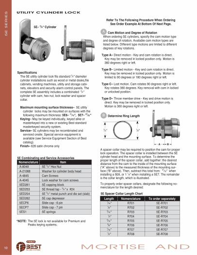
UTILITY CYLINDER LOCK
Refer To The Following Procedure When OrderingSee Order Example At Bottom Of Next Page.
Cam Motion and Degree of RotationWhen ordering 5E cylinders, specify the cam motion typeand degree of rotation. Available cam motion types are listed below. Different type motions are limited to differentdegrees of key rotations.
Type A– Direct motion - Key and cam rotation is direct. Key may be removed in locked position only. Motion is 360 degrees right or left.
Type B– Limited motion - Key and cam rotation is direct. Key may be removed in locked position only. Motion is limited to 90 degrees or 180 degrees right or left.
Type C– Lost motion. Cam rotates 90 degrees right or left. Key rotates 360 degrees. Key removal with cam in locked or unlocked position.
Type D– Throw member drive - Key and drive motion is direct. Key may be removed in locked position only. Motion is 360 degrees right or left.
5E– 3/4" CylinderA
B
5E S
ER
IES
Determine Ring Length
7⁄8"3⁄4"
Length Nomenclature To order separately1⁄16" R701 5E-R7011⁄8" R702 5E-R7023⁄16" R703 5E-R7031⁄4" R704 5E-R704
5⁄16" R705 5E-R7053⁄8" R706 5E-R7067⁄16" R707 5E-R7071⁄2" R708 5E-R708
SpecificationsThe 5E utility cylinder lock fits standard 3⁄4" diametercylinder installations such as wood or metal desks,filecabinets, vending machines, utility and storage cabi-nets, elevators and security alarm control panels. Thecomplete 5E assembly includes a combinated 3⁄4"cylinder with cam, hex nut, lock washer and spacer collar.
Maximum mounting surface thickness– 5E utility cylinder locks may be mounted on surfaces with the following maximum thickness: 5E6– 11⁄16", 5E7– 27⁄32"
Keying– May be keyed individually, keyed alike or masterkeyed into a new or existing Best standard masterkeyed security system.
Service– 5E cylinders may be recombinated and serviced onsite. Special service equipment is available (see Service Equipment Section of Bestcatalog).
Finish– 626 satin chrome only
5E Combinating and Service AccessoriesNomenclature ItemA-8049 5E 3/4" Hex NutA-21068 Washer for cylinder body headA-4845 Cam ScrewsA-4045 Lock washer for cam screws5ED261 5E capping block5ED253 5E thread tap - 3/4" x #245ED254 5E 3/4" metal punch and die set (slab)5ED262 5E cap depressor5ECP6 Slide cap - 6 pin5ECP7 Slide cap - 7 pin5ES1 5E springs
5E Spacer Collar Length Chart
5E 7 A 1 C R708 4B 20 12 R 90 626Series Lock Keyway Combinating Cam Ring Cam Cam Mouting Cam Degree of Finish
Body Code Motion Length Type Length Position Direction Rotation
5E–3/4" 6-6 pin designate 1– uncomb. A-direct R701- 1/16" C1-fixed straight 10- 5/ 8" 3– 3 o’clock R– right 90– 90° 6267-7 pin specific 2-A2 system B-limited R702- 1/ 8" 2A-fixed offset in 12- 3/ 4" 6– 6 o’clock L– left 180–180° stan-
keyway 3-A3 system C-lost R703- 3/16" 2B-fixed offset out 14- 7/ 8" 9– 9 o’clock (see E 360– 360° dard(A,E etc.) 4-A4 system D-throw R704- 1/ 4" C3-lost motion 16- 1" 12–12 o’clock above) (see A
member R705- 5/16" 4A-lost motion etc., in (see E above) page 10)drive R706- 3/ 8" offset in 1/16" of (see A etc. 4B-lost motion an inchpage 10) (see B offset out (see D
page 10) D-direct above)(see C above)
11 RIM CYLINDERS
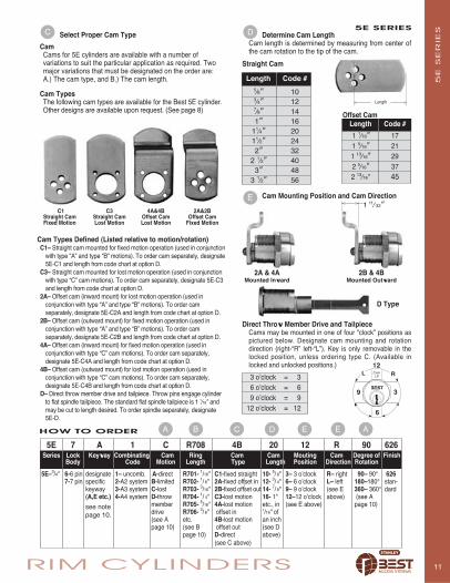
Cam Mounting Position and Cam Direction
5E SERIES
3 o’clock = 36 o’clock = 69 o’clock = 9
12 o’clock = 12
Determine Cam LengthCam length is determined by measuring from center ofthe cam rotation to the tip of the cam.
Straight Cam
Cam Types Defined (Listed relative to motion/rotation)C1– Straight cam mounted for fixed motion operation (used in conjunction
with type “A” and type “B” motions). To order cam separately, designate 5E-C1 and length from code chart at option D.
C3– Straight cam mounted for lost motion operation (used in conjunction with type “C” cam motions). To order cam separately, designate 5E-C3 and length from code chart at option D.
2A– Offset cam (inward mount) for lost motion operation (used in conjunction with type “A” and type “B” motions). To order cam separately, designate 5E-C2A and length from code chart at option D.
2B– Offset cam (outward mount) for fixed motion operation (used in conjunction with type “A” and type “B” motions). To order cam separately, designate 5E-C2B and length from code chart at option D.
4A– Offset cam (inward mount) for fixed motion operation (used in conjunction with type “C” cam motions). To order cam separately, designate 5E-C4A and length from code chart at option D.
4B– Offset cam (outward mount) for lost motion operation (used in conjunction with type “C” cam motions). To order cam separately, designate 5E-C4B and length from code chart at option D.
D– Direct throw member drive and tailpiece. Throw pins engage cylinder to flat spindle tailpiece. The standard flat spindle tailpiece is 1 1⁄16" and may be cut to length desired. To order spindle separately, designate 5E-D.
C1 C3 4A&4B 2A&2BStraight Cam Straight Cam Offset Cam Offset CamFixed Motion Lost Motion Lost Motion Fixed Motion
2A & 4A 2B & 4BMounted Inward Mounted Outward
D Type
Direct Throw Member Drive and TailpieceCams may be mounted in one of four "clock” positions aspictured below. Designate cam mounting and rotationdirection (right-“R” left-“L”). Key is only removable in thelocked position, unless ordering type C. (Available inlocked and unlocked positions.)
DC
A B E E A
Select Proper Cam Type
CamCams for 5E cylinders are available with a number of variations to suit the particular application as required. Two major variations that must be designated on the order are: A.) The cam type, and B.) The cam length.
Cam TypesThe following cam types are available for the Best 5E cylinder.Other designs are available upon request. (See page 8)
HOW TO ORDER C D5E S
ER
IES
Offset CamLength Code #
1 1⁄16" 171 5⁄16" 211 13⁄16" 292 5⁄16" 372 13⁄16" 45
Length Code #5⁄8" 103⁄4" 127⁄8" 141" 16
11⁄4" 2011⁄2" 242" 32
2 1⁄2" 403" 48
3 1⁄2" 56
E
Length
1 11⁄ 32"
see notepage 10.

CY
LIN
DER
S
© 2005 Stanley Security Solutions, Inc and Stanley Logistics
For more information on BEST’s full line of security solutions visit our web site at www.stanleysecuritysolutions.comor call 1-317-849-2250 for the name of the Best Access Systems office nearest you.
Best Access SystemsA Division of Stanley Security Solutions, Inc.
6161 E. 75th Street Indianapolis, Indiana 46250www.stanleysecuritysolutions.com
Product information contained in this catalog has been compiled and presented with as much care and completeness as is reasonably possible. Errors or mistakes may be present, and in many cases, reliance has been placed on information supplied by other manufacturers which may be in error or which maybe subject to changes or modifications by the manufacturer without notice and without obligation. Therefore, no guarantee can be made or should beassumed or implied with regards to product information contained in this catalog. Peaks® is a registered trademark of KABA® High Security Locks Corporation.
Product Warranty – Best Access Systems warrants that all of its products sold under its trade name "BEST" are free of defects in materials, workmanshipand operation, normal wear and tear excepted, for a period of three years from the date of sale to the original purchaser.
Concerning Proper Installation: Installation instructions for any Best Access Systems product should be carefully followed for proper operation of theinstalled product. If improperly installed, malfunction of the product may result.
10M 605 FPB-209 Litho USA