e-series/e1015 laser marking systemstelesis.com/pdf/78959.pdf4. place the laser controller, monitor,...
TRANSCRIPT
E-series/E1015 Laser Marking Systems
78959A © 2017 Telesis Technologies, Inc. – All Rights Reserved 1 of 15
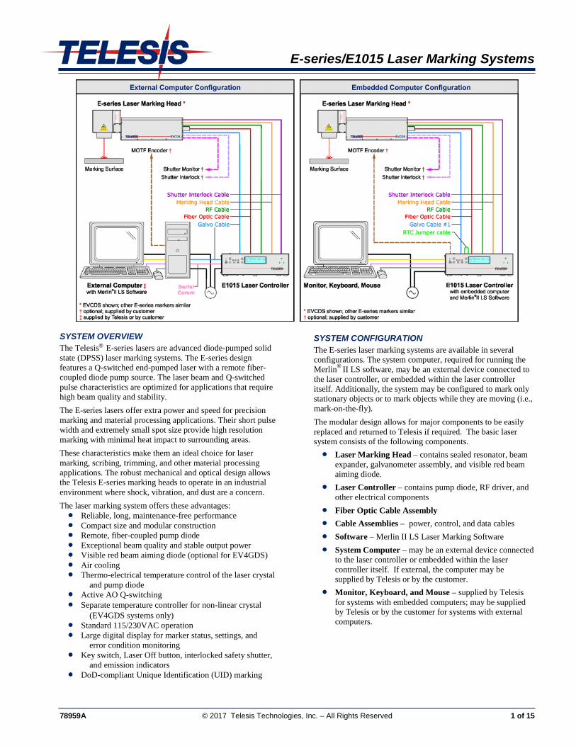
SYSTEM OVERVIEW The Telesis® E-series lasers are advanced diode-pumped solid state (DPSS) laser marking systems. The E-series design features a Q-switched end-pumped laser with a remote fiber-coupled diode pump source. The laser beam and Q-switched pulse characteristics are optimized for applications that require high beam quality and stability. The E-series lasers offer extra power and speed for precision marking and material processing applications. Their short pulse width and extremely small spot size provide high resolution marking with minimal heat impact to surrounding areas. These characteristics make them an ideal choice for laser marking, scribing, trimming, and other material processing applications. The robust mechanical and optical design allows the Telesis E-series marking heads to operate in an industrial environment where shock, vibration, and dust are a concern. The laser marking system offers these advantages: • Reliable, long, maintenance-free performance • Compact size and modular construction • Remote, fiber-coupled pump diode • Exceptional beam quality and stable output power • Visible red beam aiming diode (optional for EV4GDS) • Air cooling • Thermo-electrical temperature control of the laser crystal
and pump diode • Active AO Q-switching • Separate temperature controller for non-linear crystal
(EV4GDS systems only) • Standard 115/230VAC operation • Large digital display for marker status, settings, and
error condition monitoring • Key switch, Laser Off button, interlocked safety shutter,
and emission indicators • DoD-compliant Unique Identification (UID) marking
SYSTEM CONFIGURATION The E-series laser marking systems are available in several configurations. The system computer, required for running the Merlin® II LS software, may be an external device connected to the laser controller, or embedded within the laser controller itself. Additionally, the system may be configured to mark only stationary objects or to mark objects while they are moving (i.e., mark-on-the-fly). The modular design allows for major components to be easily replaced and returned to Telesis if required. The basic laser system consists of the following components. • Laser Marking Head – contains sealed resonator, beam
expander, galvanometer assembly, and visible red beam aiming diode.
• Laser Controller – contains pump diode, RF driver, and other electrical components
• Fiber Optic Cable Assembly • Cable Assemblies – power, control, and data cables • Software – Merlin II LS Laser Marking Software • System Computer – may be an external device connected
to the laser controller or embedded within the laser controller itself. If external, the computer may be supplied by Telesis or by the customer.
• Monitor, Keyboard, and Mouse – supplied by Telesis for systems with embedded computers; may be supplied by Telesis or by the customer for systems with external computers.
E-series/E1015 Laser Marking Systems
2 of 15 78959A
SPECIFICATIONS
E-series/E1015 System Specifications Compliance .................................... CDRH,CE Laser Type
EVCDS, EV15DS, EV10SDS . fiber-coupled, diode-pumped, Q-switched, Nd:YVO4
EV4GDS ................................... fiber-coupled, frequency-doubled, diode-pumped, Q-switched, Nd:YVO4
Wavelength EVCDS, EV15DS, EV10SDS .............................. 1064 nanometers (nm) EV4GDS ................................... 532 nanometers (nm)
Mode .............................................. TEM- 00 Long Term Output Power Drift ..... < ± 2% Laser Diode MTTF
EVCDS...................................... 500,000 hours EV10SDS .................................. 200,000 hours EV15DS, EV4GDS .................. 250,000 hours
Power Requirements EVCDS...................................... 95 to 250 VAC, single-phase,
6A, 50/60 Hz EV10SDS, EV15DS, EV4GDS ............................... 115 VAC, single-phase,
9.0A, 50/60Hz to 230 VAC, single-phase, 4.5A, 50/60Hz
System Power (total) EVCDS...................................... < 400 watts EV10SDS, EV15DS ................. < 500 watts EV4GDS ................................... < 600 watts
Maximum Supply Voltage ............. 264 VAC Supply Voltage Fluctuation ............ < ±10% with clean ground line Operational Temperature
EVCDS...................................... 15° to 35°C (59° to 95°F) EV10SDS, EV15DS, EV4GDS ............................... 18° to 35°C (65° to 95°F)
Recommended Temperature .......... 20° to 25°C (68° to 77°F) Ambient Relative Humidity ............ 10% to 85% non-condensing Cooling ........................................... air cooled, active thermo-
electric Fiber Optic Cable Length .............. 1.75 m (5.74 ft.) – standard
4.75 m (15.58 ft.) – optional
E-series Laser Marking Head Specifications Dimensions (L x W x H)*
EVCDS ................................. 611.33 x 153.80 x 188.93 mm (24.068 x 6.055 x 7.438 in.)
EV10SDS ............................. 794.8 x 176.9 x 180.3 mm (31.3 x 7.0 x 7.1 in.)
EV15DS ............................... 719.0 x 162.0 x 191.6 mm (28.3 x 6.4 x 7.5 in.)
EV4GDS .............................. 805.95 x 248.49 x 196.68 mm (31.730 x 9.783 x 7.744 in.)
* Length includes rear panel interlock switch (part of fiber cable)
Surrounding Envelope .............. see E-series Laser Marking Head Dimensions drawings
Electrical Power EVCDS ................................. 210 watts (approximate) EV10SDS ............................. 270 watts (approximate) EV15DS ............................... 260 watts (approximate) EV4GDS ............................... 280 watts (approximate)
Mounting Weight EVCDS ................................. approximately 14.5 Kg (32 lbs.) EV10SDS, EV15DS ............ approximately 20 Kg (44 lbs.) EV4GDS .............................. approximately 25 Kg (55 lbs.)
Mounting EVCDS, EV10SDS, and EV15DS ........................... three M5-0.80 mounting bolts EV4GDS .............................. six M5-0.80 mounting bolts EVCDS, EV15DS ................ three 0.2362P6 locating pins
Positioning ................................ visible red beam aiming diode (optional for EV4GDS)
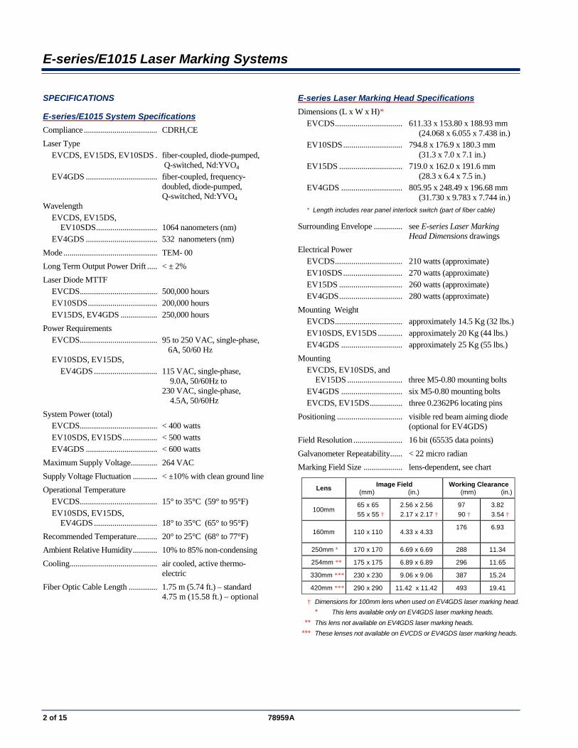
Field Resolution ........................ 16 bit (65535 data points) Galvanometer Repeatability ...... < 22 micro radian Marking Field Size ................... lens-dependent, see chart
Lens Image Field (mm) (in.)
Working Clearance (mm) (in.)
100mm 65 x 65
55 x 55 † 2.56 x 2.56
2.17 x 2.17 † 97
90 † 3.82
3.54 †
160mm 110 x 110 4.33 x 4.33 176
6.93
250mm * 170 x 170 6.69 x 6.69 288 11.34
254mm ** 175 x 175 6.89 x 6.89 296 11.65
330mm *** 230 x 230 9.06 x 9.06 387 15.24
420mm *** 290 x 290 11.42 x 11.42 493 19.41 † Dimensions for 100mm lens when used on EV4GDS laser marking head. * This lens available only on EV4GDS laser marking heads. ** This lens not available on EV4GDS laser marking heads. *** These lenses not available on EVCDS or EV4GDS laser marking heads.
E-series/E1015 Laser Marking Systems
78959A 3 of 15
SPECIFICATIONS (continued)
E1015 Laser Controller Specifications Dimensions (W x H x D)....... 425.45 x 140.46 x 487.68 mm
(16.75 x 5.53 x 19.20 in.) Surrounding Envelope ........... see E1015 Laser Controller
Dimensions drawing Weight ................................... approximately 15 Kg (33 lbs.) Cooling .................................. air cooled, active thermo-electric
System Computer Specifications The system computer may be embedded within the controller or an external unit connected to the controller.
Embedded System Computers Operating System .......... Windows® Embedded Standard Operator Interface .......... Telesis Merlin II LS Software Processor ....................... Intel® Atom™ 1.60 GHz RAM .............................. 2 GB Comm Ports ................... Two TCP/IP Ethernet Ports,
Four RS-232 Serial Ports, Four USB Ports (back panel) One USB Port (front panel)
Circuit Cards ................. Laser/Galvo Controller Board, Video Board
External System Computers If supplied by anyone other than Telesis, the system computer must, at a minimum, meet the following specifications:
Operating System .......... Windows® 2000, XP, Vista® (Business), 7 (professional) or 8 (Professional)
Operator Interface .......... Telesis Merlin II LS Laser Marking Software
Processor ....................... Pentium® III with RAM as recommended per operating system
Hard Drive ..................... 2 GB Hard Disk Drive External Drives .............. CD-ROM Drive Comm Ports ................... One available RS-232 Serial Port,
Two available USB Ports, Two available Ethernet Ports, Three available full-height PCIe Slots (1)
Circuit Cards ................. Laser/Galvo Controller Board, Video Board
Peripherals ..................... SVGA Color Monitor, Mouse (2), Keyboard (2)
(1) One additional PCIe slot required if system is configured for mark-on-the-fly operation. If the system computer is a notebook, expansion must be used to provide the PCIe slots.
(2) Telesis recommends a USB mouse and a USB keyboard for system computers that are embedded in the laser controller.
EV4GDS Temperature Controller Specifications The EV4GDS uses a separate temperature controller for the non-linear crystal .
Dimensions (W x H x D) ....... 212.85 x 96.09 x 211.79 mm (8.380 x 3.783 x 8.338 in.)
Weight ................................... approximately 1.82 Kg (4 lbs.) Cooling .................................. air cooled, ambient air
SYSTEM OPTIONS
• External computer (desktop or notebook with powered cardbus-to-PCIe expansion enclosure) to run the Merlin II LS Laser Marking Software
• Embedded computer within the laser controller to run the Merlin II LS Laser Marking Software
• Laser Controller Fuse/Connector Kit
• Remote pushbutton station (start/abort)
• Co-axial visible red beam aiming diode (optional for EV4GDS; standard for all other E-series lasers)
• Externally-mounted focus-finder diode
• Mark-on-the-fly kit to interface with customer-supplied encoder for marking objects in motion (linear or circular)
• I/O options (see Remote Communications for details)
• Manually operated tool post for vertical (z-axis) adjustment
• Programmable tool post for vertical (z-axis) adjustment (requires two-axis controller)
• Rotary drive fixture for rotational (theta-axis) adjustment (requires two-axis controller)
• Workstation / work area enclosure
• Fume extraction systems
E-series/E1015 Laser Marking Systems
4 of 15 78959A
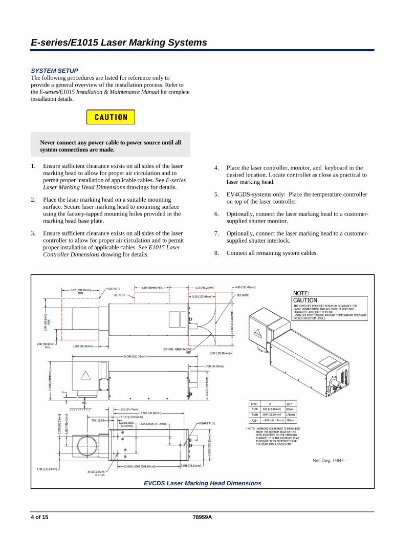
SYSTEM SETUP The following procedures are listed for reference only to provide a general overview of the installation process. Refer to the E-series/E1015 Installation & Maintenance Manual for complete installation details.
Never connect any power cable to power source until all system connections are made.
1. Ensure sufficient clearance exists on all sides of the laser marking head to allow for proper air circulation and to permit proper installation of applicable cables. See E-series Laser Marking Head Dimensions drawings for details.
2. Place the laser marking head on a suitable mounting surface. Secure laser marking head to mounting surface using the factory-tapped mounting holes provided in the marking head base plate.
3. Ensure sufficient clearance exists on all sides of the laser controller to allow for proper air circulation and to permit proper installation of applicable cables. See E1015 Laser Controller Dimensions drawing for details.
4. Place the laser controller, monitor, and keyboard in the desired location. Locate controller as close as practical to laser marking head.
5. EV4GDS-systems only: Place the temperature controller on top of the laser controller.
6. Optionally, connect the laser marking head to a customer-supplied shutter monitor.
7. Optionally, connect the laser marking head to a customer-supplied shutter interlock.
8. Connect all remaining system cables.
EVCDS Laser Marking Head Dimensions
E-series/E1015 Laser Marking Systems
78959A 5 of 15
EV4GDS Laser Marking Head Dimensions (Sheet 1 of 2)
EV4GDS Laser Marking Head Dimensions (Sheet 2 of 2)
E-series/E1015 Laser Marking Systems
6 of 15 78959A
EV15DS Laser Marking Head Dimensions
EV10SDS Laser Marking Head Dimensions
E-series/E1015 Laser Marking Systems
78959A 7 of 15
E1015 Laser Controller Dimensions (external computer configuration)
E1015 Laser Controller Dimensions (external computer configuration)
E-series/E1015 Laser Marking Systems
8 of 15 78959A
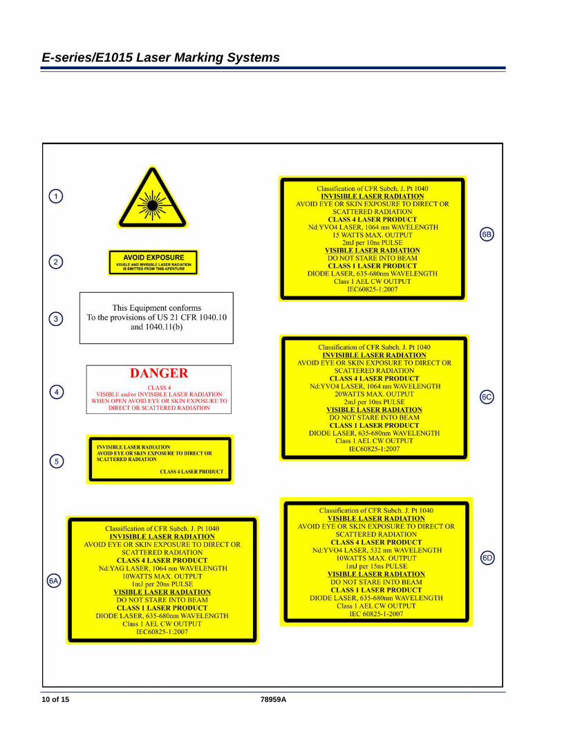
E1015 LASER CONTROLLER SAFETY LABELS The following illustration shows the labels and their locations on the E1015 laser controller. Please familiarize yourself with the laser labels and their locations prior to operating the laser marking system.
E-series/E1015 Laser Marking Systems
78959A 9 of 15
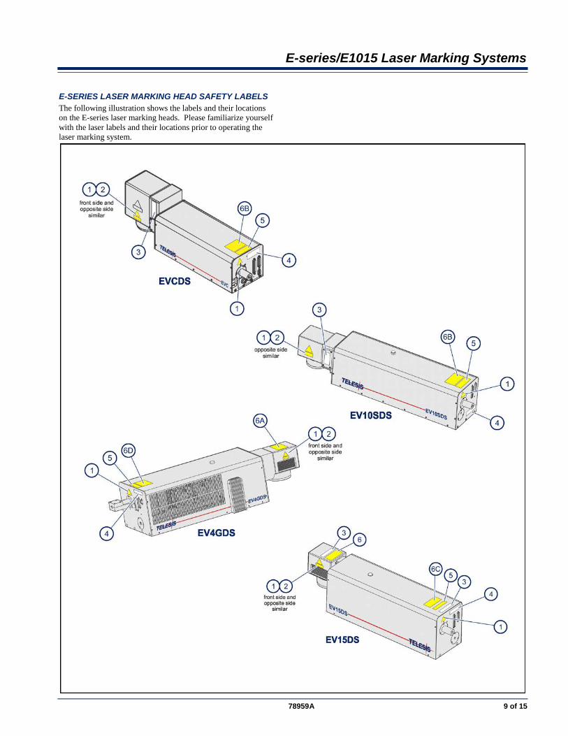
E-SERIES LASER MARKING HEAD SAFETY LABELS The following illustration shows the labels and their locations on the E-series laser marking heads. Please familiarize yourself with the laser labels and their locations prior to operating the laser marking system.
E-series/E1015 Laser Marking Systems
10 of 15 78959A
E-series/E1015 Laser Marking Systems
78959A 11 of 15
E-SERIES LASER MARKING HEAD E-series lasers are designed for easy maintenance. The laser marking head encloses the sealed laser resonator, the beam expander, the visible red beam aiming diode, and the galvanometer assembly. Heat exhaust fans are located on the right side of the units.
Sealed Laser Resonator The laser resonator is assembled and sealed in the clean room environment to prevent contamination. The laser marking head contains an electro-mechanical safety shutter. Under power, the safety shutter allows the laser beam to pass through the galvanometer steering mirrors. If the shutter is closed during normal operation (or power is removed from the system via a power off/stop condition) it will block the laser beam.
Visible Red Beam Aiming Diode Note: The aiming diode is an optional feature for the EV4GDS laser marking head. It is standard for all other E-series markers. The laser marking head produces a visible red beam aiming diode that may be viewed on the work surface without the need for protective safety goggles. This provides a safe and convenient aid for laser setup and part programming. Since the aiming diode is located after the shutter, the visible red beam may be used with the shutter opened or closed. Additionally, the red beam may be used with the lasing beam during the marking cycle. Note that protective eyewear must always be worn when the laser is in operation.
Shutter Monitor The E-series laser marking head employs a self-monitoring safety circuit using two separate sensors to detect the closed-state of the laser shutter mechanism. The sensor signals can be monitored at the DB9P Dual Sensor connector on the back panel of the laser marking head. When the shutter is open, the sensor feedback signals are OFF. When the shutter is closed, the sensor feedback signals are ON.
Shutter Interlock The E-series laser marking head employs a Shutter Interlock Input connector and a Shutter Interlock Output connector. An optional, customer-supplied shutter interlock can be connected to the Input connector. The Shutter Interlock cable (provided) connects the Output connector to the laser controller.
Marking Field Size The size of the marking field is dependent on the lens installed on the laser marking head. See E-series Laser Marking Head Specifications.
Marking Depth Simple laser parameters can be operator programmed to create depths ranging from simple surface discoloration, shallow laser
etching, or deep laser engraving. Marking depth is dependent on several factors including material, lens selected, and laser marking parameters. Please contact Telesis for the proper setting for your specific application.
Flat-Field Lens The flat-field lens is key to the marking performance of the system. This is the final coated optical lens that the beam will pass through before it strikes the marking target. This lens is called a flat field lens because when the beam is focused, the focus lies in a plane perpendicular to the optical axis of the lens. To protect the final objective lens from dust and debris, a clear protective cover is inserted between the work area and the lens.
E1015 LASER CONTROLLER The pump diode is enclosed in the laser controller, while the laser resonator with the crystal is located in the laser marking head. The pump beam from the diode (approx. 808nm) is delivered through a fiber optic cable directly into the laser resonator. This compact laser controller can be fitted to any standard-rack mount or it can be placed directly upon a desktop. The laser controller also contains the active thermo-electrical cooling system for the pump diode, the RF driver, galvanometer power supply, driver control circuits, appropriate fusing, and a 115/230VAC IEC320 connector, and a front panel control module. Engineered for the greatest reliability and for ease of maintenance, the pump diode within the laser controller is an easily replaceable sealed module with a long MTTF providing many maintenance-free operating hours.
Fiber Optic Cable Assembly The fiber optic cable is permanently attached to the pump diode within the laser controller and cannot be removed. The standard optical fiber is 1.75 meters (5.74 feet) long. An optional 4.75 meter (15.58 ft.) fiber optic cable is also available. The fiber optic cable assembly contains an interlock switch assembly. The fiber optic cable must be connected to the laser marking head to close the laser interlock circuit. If the cable is disconnected, the laser interlock circuit will open.
E-series/E1015 Laser Marking Systems
12 of 15 78959A
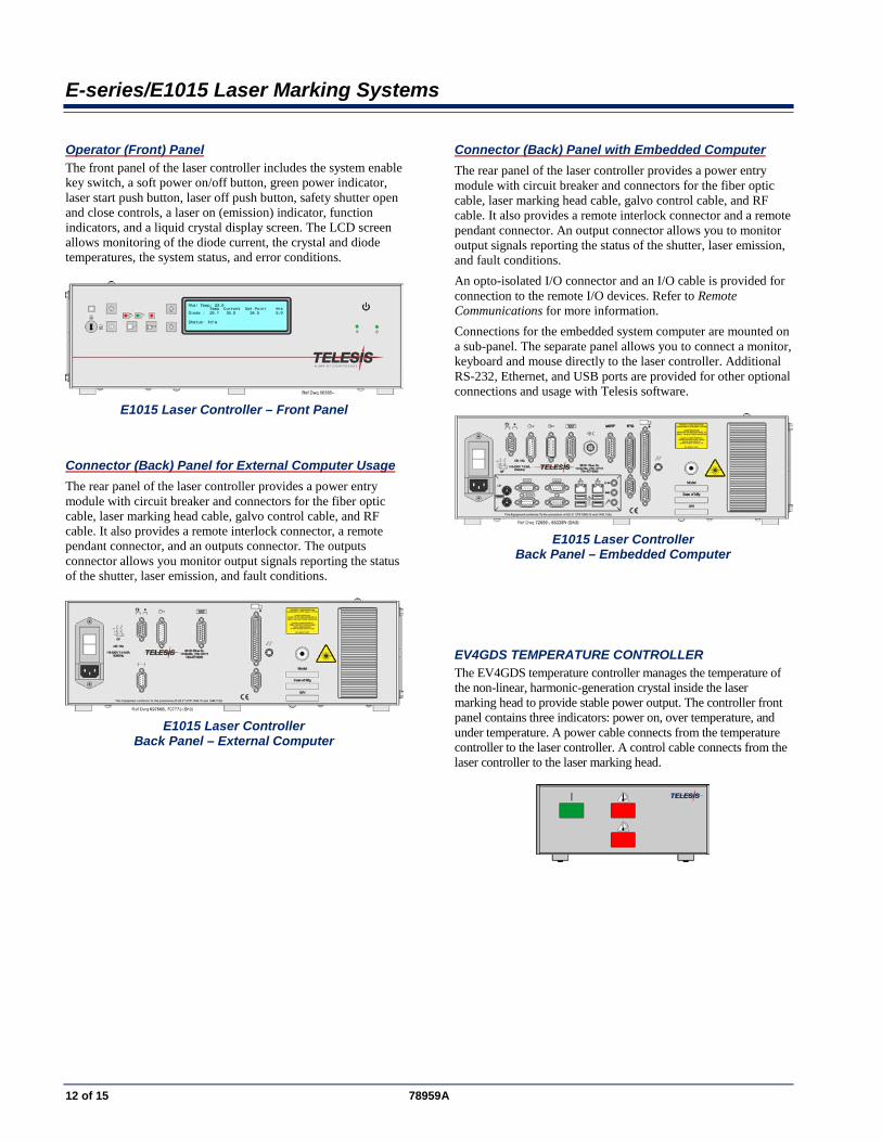
Operator (Front) Panel The front panel of the laser controller includes the system enable key switch, a soft power on/off button, green power indicator, laser start push button, laser off push button, safety shutter open and close controls, a laser on (emission) indicator, function indicators, and a liquid crystal display screen. The LCD screen allows monitoring of the diode current, the crystal and diode temperatures, the system status, and error conditions.
E1015 Laser Controller – Front Panel
Connector (Back) Panel for External Computer Usage The rear panel of the laser controller provides a power entry module with circuit breaker and connectors for the fiber optic cable, laser marking head cable, galvo control cable, and RF cable. It also provides a remote interlock connector, a remote pendant connector, and an outputs connector. The outputs connector allows you monitor output signals reporting the status of the shutter, laser emission, and fault conditions.
E1015 Laser Controller
Back Panel – External Computer
Connector (Back) Panel with Embedded Computer The rear panel of the laser controller provides a power entry module with circuit breaker and connectors for the fiber optic cable, laser marking head cable, galvo control cable, and RF cable. It also provides a remote interlock connector and a remote pendant connector. An output connector allows you to monitor output signals reporting the status of the shutter, laser emission, and fault conditions. An opto-isolated I/O connector and an I/O cable is provided for connection to the remote I/O devices. Refer to Remote Communications for more information. Connections for the embedded system computer are mounted on a sub-panel. The separate panel allows you to connect a monitor, keyboard and mouse directly to the laser controller. Additional RS-232, Ethernet, and USB ports are provided for other optional connections and usage with Telesis software.
E1015 Laser Controller
Back Panel – Embedded Computer
EV4GDS TEMPERATURE CONTROLLER The EV4GDS temperature controller manages the temperature of the non-linear, harmonic-generation crystal inside the laser marking head to provide stable power output. The controller front panel contains three indicators: power on, over temperature, and under temperature. A power cable connects from the temperature controller to the laser controller. A control cable connects from the laser controller to the laser marking head.
E-series/E1015 Laser Marking Systems
78959A 13 of 15
SYSTEM COMPUTER The laser system requires an IBM-compatible computer for running the Merlin II LS Laser Marking Software. The system computer may be an external device connected to the laser controller, or it may be embedded within the controller itself.
N O T I C E
Merlin II LS software and associated applications are pre-installed on the embedded computer. The embedded system supports Telesis-installed software only and does not support user-installed programs.
All system computers supplied by Telesis (external and embedded) have the laser/galvo controller board and the Merlin II LS software installed prior to shipment so the entire assembly is tested as a laser marking system. Warranties for the computer, keyboard, monitor, and peripherals default to the original equipment manufacturer.
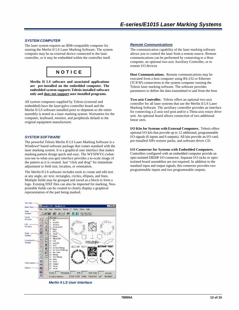
SYSTEM SOFTWARE The powerful Telesis Merlin II LS Laser Marking Software is a Windows® based software package that comes standard with the laser marking system. It is a graphical user interface that makes marking pattern design quick and easy. The WYSIWYG (what-you-see-is-what-you-get) interface provides a to-scale image of the pattern as it is created. Just “click and drag” for immediate adjustment to field size, location, or orientation. The Merlin II LS software includes tools to create and edit text at any angle, arc text, rectangles, circles, ellipses, and lines. Multiple fields may be grouped and saved as a block to form a logo. Existing DXF files can also be imported for marking. Non-printable fields can be created to clearly display a graphical representation of the part being marked.
Merlin II LS User Interface
Remote Communications The communication capability of the laser marking software allows you to control the laser from a remote source. Remote communications can be performed by connecting to a Host computer, an optional two-axis Auxiliary Controller, or to remote I/O devices.
Host Communications. Remote communications may be executed from a host computer using RS-232 or Ethernet (TCP/IP) connections to the system computer running the Telesis laser marking software. The software provides parameters to define the data transmitted to and from the host.
Two-axis Controller. Telesis offers an optional two-axis controller for all laser systems that use the Merlin II LS Laser Marking Software. The auxiliary controller provides an interface for connecting a Z-axis tool post and/or a Theta-axis rotary drive unit. An optional board allows connection of two additional linear axes.
I/O Kits for Systems with External Computers. Telesis offers optional I/O kits that provide up to 12 additional, programmable I/O signals (6 inputs and 6 outputs). All kits provide an I/O card, pre-installed SIPs resistor packs, and software driver CD.
I/O Connector for Systems with Embedded Computers. Controllers configured with an embedded computer provide an opto-isolated DB26P I/O connector. Separate I/O racks or opto-isolated board assemblies are not required. In addition to the standard input and output signals, this connector provides two programmable inputs and two programmable outputs.
E-series/E1015 Laser Marking Systems
14 of 15 78959A
Communications Protocol Two types of host interface are supported (RS-232 or TCP/IP) and two communication protocols are provided through the Merlin II LS laser marking software: Extended and Programmable.
Extended Protocol Extended protocol provides two-way communication with error checking and transmission acknowledgment. It is designed to provide secure communications with an intelligent host device using pre-defined message formats and response formats where serial communication is a vital part of the marking operation. All communications are carried out in a parent/child relationship with the host being the parent. Only the host has the ability to initiate communications. The Extended Protocol message is transmitted using the following format.
SOH TYPE [##] STX [DATA] ETX BCC CR
The message type is defined by a single, printable ASCII character. The Extend Protocol message types are: Message Type 1 provides data to a text string in the pattern or polls the pattern for data. Message Type A provides data to the system Offset Angle parameter for the marking window or polls the system for data. Message Type E allows the host to take the machine offline. It also provides the option of displaying an error message box with the provided data string. Message Type G initiates a print cycle. Message Type H provides data to the system X/Y Offset parameters or polls the system for data. Message Type I polls the system for the I/O status. Message Type O places the marker online. This allows a host computer to reset. This may be used to recover from a power outage when the marker is unattended. Message Type P loads a pattern or polls the system for the current pattern name. Message Type Q provides data to the system query text buffer or polls the system for data. Message Type S polls the system for the machine status. The machine status is returned to the host in an eight-character hexadecimal mask. Message Type V provides data to a variable text string in the pattern or polls the pattern for data.
Programmable Protocol Programmable protocol provides one-way (receive only) communication with no error checking or acknowledgment of the transmitted data. You may use Programmable protocol to extract a continuous portion of a message string to print. This can be used with a host computer or a bar code scanner. Note that XON/XOFF Protocol applies even when Programmable Protocol is selected. The Programmable Protocol Message Type identifies the type of message sent from the host. It determines how the marker uses the data it extracts from the host message string when Programmable Protocol is used. The Programmable Protocol message types are: Message Type 49 (ASCII 1) overwrites the content of the first text-based field in the pattern with the data extracted from the host message. Message Type 65 (ASCII A) updates the Offset Angle parameter for the marking window using data extracted from the host message. Message Type 72 (ASCII H) updates the Offset X/Y parameters for the marking window using data extracted from the host message. Message Type 80 (ASCII P) indicates the data extracted from the host message is the name of the pattern to be loaded. Message Type 81 (ASCII Q) updates the text in the first query text buffer (buffer 0) with the data extracted from the host message. Message Type 86 (ASCII uppercase V) updates the text in the first variable text field in the pattern with the data extracted from the host message. Message Type 118 (ASCII lowercase v) updates the first text field encountered in the pattern that contains a variable text flag that matches the specified string length. Message Type 0 (zero) indicates that host will provide message type, field number (if applicable), and data. This delegates message type selection to the host on message-by-message basis.
TRADEMARKS Telesis and Merlin are registered trademarks of Telesis Technologies, Inc. in the United States and/or other countries.
Atom is a trademarks of Intel Corporation in the United States and other countries.
Intel and Pentium are registered trademarks of Intel Corporation in the United States and other countries.
Windows and Vista are registered trademarks of Microsoft Corporation in the United States and other countries.
E-series/E1015 Laser Marking Systems
78959A 15 of 15