e - theory/operation article text 1992 nissan …nissan-nv.narod.ru/data/e_theory.pdfinputs from the...
TRANSCRIPT

E - THEORY/OPERATIONArticle Text
1992 Nissan 300ZXFor dasaer mira sakhalin Russia 34243423
Copyright © 1998 Mitchell Repair Information Company, LLCSaturday, May 31, 2003 02:12AM
ARTICLE BEGINNING
1992 ENGINE PERFORMANCE Nissan Theory & Operation
Maxima, NX, Pathfinder, Pickup, Sentra, Stanza, 240SX, 300ZX
INTRODUCTION
This article covers basic description and operation of engineperformance-related systems and components. Read this article beforediagnosing vehicles or systems with which you are not completelyfamiliar.
AIR INDUCTION SYSTEM
POWER VALVE SYSTEM (MAXIMA)
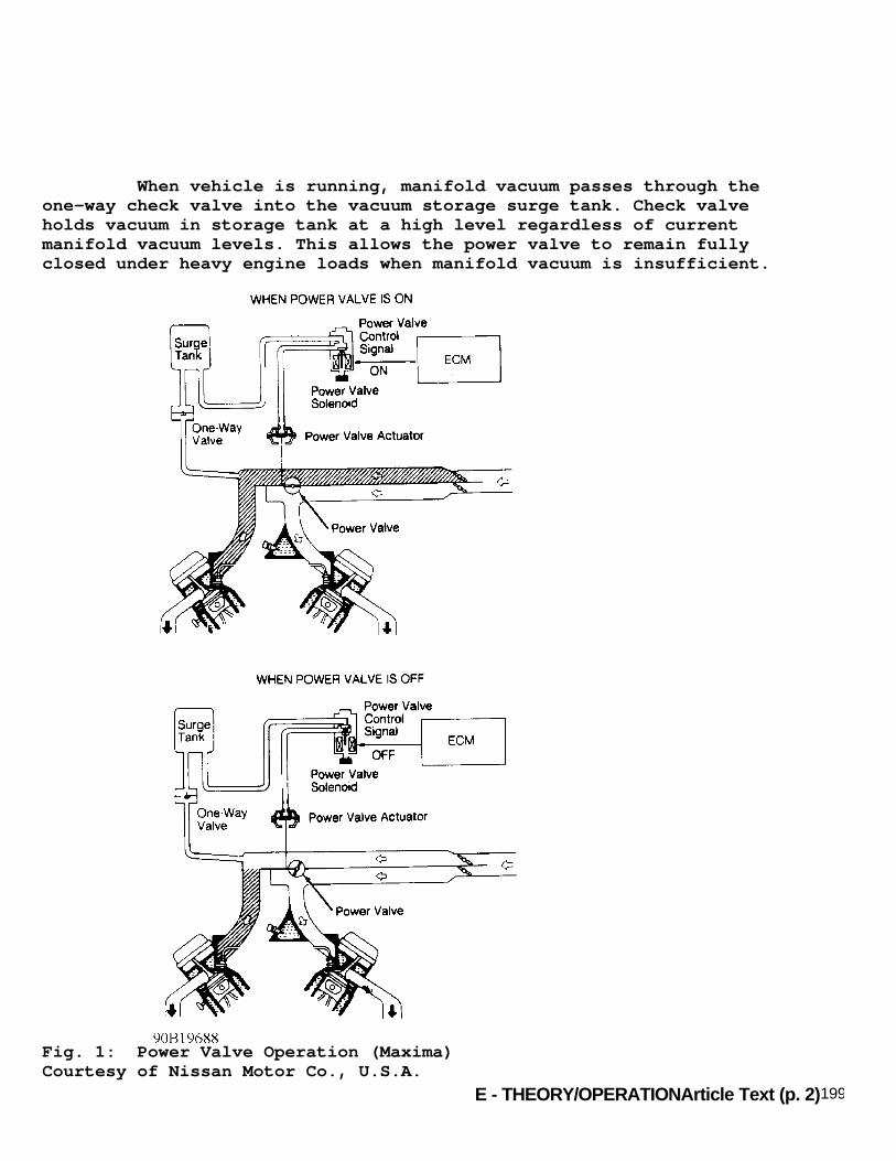
The power valve system is designed to improve engine torqueand power production by increasing or decreasing intake manifoldinduction volume under different driving conditions. A limitedinduction volume is desirable at low or medium speed under heavy load.This will increase intake velocity and improve atomizing of fuel andcombustion efficiency. An increased induction volume is desirableunder heavy load and high speed conditions. Power valve system consists of power valve (built intointake manifold), diaphragm type power valve actuator, vacuum surgetank, power valve solenoid, one-way check valve and connecting vacuumhoses. See Fig. 1.
Power Valve Valve is used to modify the induction passage of the powervalve control system. It is set in the fully closed or fully openposition by the power valve actuator. Power valve actuator isregulated by the ECU-controlled power valve solenoid. Vacuum foroperating the actuator is stored in a surge tank.
Power Valve Solenoid Power valve solenoid receives power from the Brown fusiblelink in the fuse box. Solenoid is energized when ECU provides a groundfor solenoid through ECU terminal No. 8. For location andidentification of ECU terminals, see appropriate wiring diagram in L -WIRING DIAGRAMS article in the ENGINE PERFORMANCE Section. When ECUactivates power valve solenoid, vacuum from surge tank passes throughsolenoid to power valve actuator, pulling the power valve closed.
Surge Tank & One-Way Check Valve
E - THEORY/OPERATIONArticle Text (p. 2)1992 Nissan 300ZX
When vehicle is running, manifold vacuum passes through theone-way check valve into the vacuum storage surge tank. Check valveholds vacuum in storage tank at a high level regardless of currentmanifold vacuum levels. This allows the power valve to remain fullyclosed under heavy engine loads when manifold vacuum is insufficient.
Fig. 1: Power Valve Operation (Maxima)Courtesy of Nissan Motor Co., U.S.A.

E - THEORY/OPERATIONArticle Text (p. 3)1992 Nissan 300ZXFor dasaer mira sakhalin Russia 34243423Copyright © 1998 Mitchell Repair Information Company, LLC
SWIRL COMBUSTION VALVE (SCV) SYSTEM (PICKUP 4-CYL., STANZA & 240SX)
Pickup 4-Cyl., Stanza & 240SX The SCV system is designed to improve engine torque and powerproduction by increasing or decreasing intake manifold inductionvolume under different driving conditions. A limited induction volumeis desirable at low or medium speed under heavy load. This willincrease intake velocity and improve atomizing of fuel and combustionefficiency. An increased induction volume is desirable under heavyload and high speed conditions. SCV system consists of swirl control valve (built intointake manifold), diaphragm type swirl control valve actuator andswirl control valve solenoid.
Swirl Control Valve Valve is used to modify the induction passage of the SCVsystem. It is set in the fully closed or fully open position by theswirl control valve actuator. Valve actuator is regulated by the ECU-controlled swirl control valve solenoid.
Swirl Control Valve Solenoid Swirl control valve solenoid receives power from a 10-ampfuse in the relay box. Solenoid is energized when ECU provides aground for solenoid through ECU terminal No. 25 (terminal No. 12 onPickup and Stanza). For location and identification of ECU terminals,see appropriate wiring diagram in L - WIRING DIAGRAMS article in theENGINE PERFORMANCE Section. When ECU activates solenoid, manifoldvacuum passes through solenoid to swirl control valve actuator,pulling swirl control valve closed.
TURBOCHARGER (300ZX TURBO)
Turbocharger system uses twin turbochargers and twin air-to-air intercoolers. A wastegate system is used to control maximum boostpressure. The wastegate is controlled by a solenoid valve.
Wastegate Control Solenoid Valve Wastegate control solenoid valve changes vacuum source towastegate valve actuator to achieve suitable turbo boost pressure.When detonation occurs, the solenoid valve turns off and openswastegate valve which lowers turbo boost pressure.
VALVE TIMING CONTROL SYSTEM (MAXIMA VE30DE, NX & SENTRA 1.6L & 300ZX)
Maxima VE30DE, NX & Sentra 1.6L & 300ZX Valve timing control system consists of intake camshaft

E - THEORY/OPERATION
pulley and advance/retard mechanism, valve timing control solenoid andoil control valve. See Fig. 2. Valve timing control is used to increase engine performanceby advancing or retarding the intake camshaft. Intake valve openingand closing points are controlled by the ECU according to engineoperating conditions. This affects the overall torque curve byallowing more favorable torque applications at low-to-medium speeds. Inputs from the coolant temperature sensor, throttle positionsensor, mass airflow sensor, engine RPM and gear position are used byECU to determine operation.
Valve Timing Control Solenoid Oil pressure, applied through the valve timing controlsolenoid is used to adjust camshaft pulley position. See Fig. 2. Atidle or high speed, valve timing control solenoid is off, valve timingis retarded and valve overlap is decreased. At low-to-medium speed,valve timing control solenoid is on, valve timing is advanced andvalve overlap is increased. This results in increased torque at lowerengine RPM.
Fig. 2: Valve Timing Control System Components (300ZX Shown;Others Are Similar)Courtesy of Nissan Motor Co., U.S.A.
COMPUTERIZED ENGINE CONTROLS
The Electronic Concentrated Control System (ECCS) is acomputerized emission, ignition, and fuel control system. A singleElectronic Control Unit (ECU) uses input voltage signals received from

E - THEORY/OPERATION
various input components to control output. ECU compares each inputsignal to the appropriate parameter preprogrammed in ECU and adjustsoutput voltage signals accordingly. This allows optimum vehicleperformance under various operating conditions. Voltage to ECU and components requiring battery voltage issupplied by a safety relay and/or a main relay. Safety relay is usedto prevent damage to ECU in the event of reverse polarity at thebattery cables. To determine power distribution to ECCS components onspecific models, see appropriate wiring diagram in L - WIRING DIAGRAMSarticle in the ENGINE PERFORMANCE Section.
ELECTRONIC CONTROL UNIT (ECU)
The ECU consists of a microcomputer, inspection lights,diagnostic mode selector, connectors and wiring for voltage signalinput, voltage signal output and power supply. The unit is notserviceable and should not be opened. Inspection lights are providedon side of unit so system operation can be checked. The control unitcontains memory and logic circuits, enabling it to interpret sensorinputs and control various engine systems.
ECU LOCATIONS TABLEÄÄÄÄÄÄÄÄÄÄÄÄÄÄÄÄÄÄÄÄÄÄÄÄÄÄÄÄÄÄÄÄÄÄÄÄÄÄÄÄÄÄÄÄÄÄÄÄÄÄÄÄÄÄÄÄÄÄÄÄApplication Location
Maxima ............................. Behind Center ConsoleNX & Sentra ........................ Behind Center ConsolePathfinder & Pickup ................. Under Passenger SeatStanza .............................. Under Center Console240SX ................... Behind Passenger Side Kick Panel300ZX ................................... Behind Glove BoxÄÄÄÄÄÄÄÄÄÄÄÄÄÄÄÄÄÄÄÄÄÄÄÄÄÄÄÄÄÄÄÄÄÄÄÄÄÄÄÄÄÄÄÄÄÄÄÄÄÄÄÄÄÄÄÄÄÄÄÄ
NOTE: Components are grouped into 2 categories. The first category covers INPUT DEVICES, which control or produce voltage signals monitored by the ECU. The second category covers OUTPUT SIGNALS, which are components controlled by the ECU.
INPUT DEVICES
Vehicles are equipped with different combinations of inputdevices. Not all devices are used on all models. To determine theinput usage on a specific model, see appropriate wiring diagram in L -WIRING DIAGRAMS article in the ENGINE PERFORMANCE Section. Theavailable input signals include the following:
A/C Switch Informs ECU when A/C system is on. ECU responds by increasing

E - THEORY/OPERATION
idle speed to improve idling and reduce emissions. During heavy engineload, ECU will also open the A/C clutch relay to disengage A/C clutch.
A/C Thermo Control Amplifier (Pickup 2.4L & Stanza) Informs ECU of A/C system evaporator outlet temperature.Input is used to determine cooling fan operation.
Air Temperature Sensor (Pickup 2.4L & Stanza) The air temperature sensor is located in the air cleaner box.Sensor monitors temperature of incoming air. Sensor is a thermistorand increases (cold) or decreases (hot) its resistance in response totemperature changes. The air temperature sensor controls ignitiontiming when intake air temperature is extremely high, to preventengine knock (detonation).
Battery Voltage Compensation Injector pulse width is directly affected by battery voltage.As battery voltage drops, so does the injector's pulse width, causinga lean air/fuel mixture. To compensate for this, ECU monitors batteryvoltage and increases injector pulse width if voltage drops. Thismonitored voltage is also used with other input values to calculateidle speed and is a factor for determining ignition timing.
Coolant Temperature Sensor Coolant temperature sensor is installed in the coolant inlethousing or intake manifold coolant passage. Sensor senses changes intemperature by monitoring the resistance of a thermistor. Astemperature increases, thermistor resistance decreases. Sensor sends temperature information to ECU for air/fuelmixture, timing and idle speed control. During warm-up from coldstart, ECU increases fuel enrichment to maintain engine performance.As engine temperature increases, the ECU gradually decreases fuelenrichment until engine reaches normal operating temperature.
Crankshaft Angle Sensor The crankshaft angle sensor monitors engine speed and pistonposition. The crankshaft angle sensor, which is built into thedistributor, has a rotor plate and a wave-forming circuit. The rotorplate has 360 small outer slits (one degree apart) to determinecrankshaft angle, and 4 (4-cylinder) or 6 (V6) larger inner signalslits (90 (4-cylinder) or 60 (V6) degrees apart) to determine enginespeed. See Fig. 7. The signal slit for the No. 1 cylinder is thelargest of the 4 (4-cylinder) or 6 (V6) inner signal slits to allowECU to determine TDC for No. 1 cylinder. When the signal rotor plate passes the space between theLight Emitting Diode (LED) and photo diode, the slits in the signalrotor plate alternately cut the light from LED to the photo diode.This causes a pulsating voltage, which is converted into an on-off

E - THEORY/OPERATION
pulse by the wave-forming circuit and sent to the ECU. ECU uses thissignal to control fuel injection, ignition timing and other functions.
Detonation (Knock) Sensor (Maxima, NX & Sentra 2.0L, Pathfinder, Pickup 3.0L, 240SX & 300ZX) Basic ignition timing is preprogrammed. Detonation sensordetects engine knocking, converts knocking vibration into voltagesignal and transmits it to the ECU. Information is used by ECU toadjust ignition timing accordingly to eliminate detonation.
Exhaust Gas (Oxygen) Sensor Sensor monitors the amount of unburned oxygen in the exhaustgases. When heated in the presence of exhaust gases, sensor provides avoltage signal which is used to adjust air/fuel mixture (amount ofinjection time) to obtain optimum combustion. Two types of oxygensensor are used. The 4-cylinder models use a Zirconia oxygen sensorwhich produces a varying voltage signal relative to the oxygen contentin the exhaust gases. The V6 models use a Titania oxygen sensor, whichis a type of resistor. The ECU provides the Titania oxygen sensor with a one-voltreference signal. Resistance of the ceramic Titania varies accordingto the exhaust gas conditions. A rich exhaust gas mixture causessensor's resistance to drop, while a lean exhaust gas mixture causesresistance to increase. The ECU monitors the return signal from sensorand adjusts the air/fuel mixture according to this return signal. Thesensor also contains an additional heating circuit to quickly bringsensor to operating temperature.
Exhaust Gas Temperature Sensor (California) The exhaust gas temperature sensor, located near EGR valve,detects temperature of exhaust gases passing through EGR valve. Thesensor has a thermistor which changes its resistance value in responseto changes in the exhaust gas temperature. As the temperature of theexhaust gases increases, the resistance of the sensor decreases. ECUanalyzes these changes in resistance and adjusts output voltagesignals to EGR solenoid accordingly.
Fuel Temperature Sensor (300ZX) The fuel temperature sensor is built into fuel rail. Whenfuel temperature is higher than specified, ECU turns on the PressureRegulator Valve (PRV) control solenoid to raise fuel pressure.
Ignition Switch Informs ECU when ignition is in ON or START position. WhenECU receives voltage signal for START position, it will actuateinjectors, compute and initiate ignition timing sequence and otherfunctions including EGR control override during start-up.

E - THEORY/OPERATIONArticle Text (p. 8)1992 Nissan 300ZXFor dasaer mira sakhalin Russia 34243423Copyright © 1998 Mitchell Repair Information Company, LLC
Inhibitor Switch (A/T) Switch is located on transmission/transaxle. Switch notifiesECU when transmission/transaxle is in Park or Neutral and signals ECUof increased engine load when vehicle is in gear. This signal is usedto calculate required changes in idle speed, ignition timing andinjector operation.
Mass Airflow Meter The mass airflow meter uses a hot-wire type sensing element.Incoming air passing through the airflow meter causes the hot wire tocool. As a result, ECU must apply additional current to maintain hotwire at the precalibrated temperature. The ECU measures airflow bymonitoring the amount of additional current required to maintain hotwire at the precalibrated temperature. On Throttle Body Injection (TBI) models, airflow meter ismounted on the side of the throttle body, where it measures a smallportion of incoming air. On Port Fuel Injection (PFI) models, airflowmeter is located in main air intake duct. If airflow meter output current is outside normal operationalrange, a malfunction in airflow meter is indicated. ECU will go tothrottle position sensor for information on driving condition. Duringthis period, ECU will limit engine speed to less than 2000 or 3000RPM, depending on model. This will inform the driver that the vehicleis driving under fail-safe conditions and needs attention. Since the hot wire is exposed to atmospheric contaminants,the ECU is programmed to clean the hot-wire each time the ignitionswitch is cycled off. This is accomplished by heating the hot wire to1832øF (1000øC) for one second after ignition has been turned off for5 seconds. This function will not occur if engine speed has notexceeded 1500 RPM, vehicle speed has not exceeded 12 MPH, engine hasstalled with ignition on, or engine is hot.
Neutral Switch (M/T) Switch is located on transmission/transaxle. Switch notifiesECU when transmission/transaxle is in Neutral and signals ECU ofincreased load when vehicle is in gear. Information is used tocalculate required changes in idle speed, ignition timing and injectoroperation.
Power Steering Oil Pressure Switch Switch is attached to the power steering high pressure line.Switch monitors the power steering load and sends signal to the ECU.When oil pressure exceeds a predetermined amount, ECU will send avoltage signal to idle speed control valve to increase idle speed.
Throttle Position Sensor (TPS) & Idle Switch The TPS has a potentiometer which varies output voltage inresponse to changes in throttle position. This information is relayed

E - THEORY/OPERATION
to the ECU in the form of an input voltage signal on the 3-terminalTPS harness. See Fig. 3. The TPS also has the ability to inform theECU of the rate of changes taking place in throttle plate movement.TPS is attached to throttle body housing and is actuated by movementof the accelerator pedal. The idle switch is an integral part of the TPS. Switch isclosed at idle and open during all other conditions. Switch is used toinform the ECU when the throttle is closed for fuel-cut ondeceleration. Switch also has a full throttle position used only onvehicles equipped with an automatic transmission control unit.
Vehicle Speed Sensor (VSS) The VSS provides ECU with vehicle speed signal. VSS consistsof a reed switch installed in the speedometer unit. Reed switchtransforms vehicle speed into pulsed signal.
Fig. 3: Throttle Position Sensor & Idle SwitchCourtesy of Nissan Motor Co., U.S.A.
OUTPUT SIGNALS
NOTE: Vehicles are equipped with different combinations of computer-controlled components. Not all components listed below are used on every vehicle. For theory and operation on each output component, refer to the indicated system under appropriate headings.
A/C Clutch See MISCELLANEOUS CONTROLS.
Air-Cut Valve See IDLE SPEED under FUEL SYSTEM.
Air Injection Valve (AIV) Control See AIR INJECTION under EMISSION SYSTEMS.

E - THEORY/OPERATIONArticle Text (p. 10)1992 Nissan 300ZXFor dasaer mira sakhalin Russia 34243423Copyright © 1998 Mitchell Repair Information Company, LLC
Air Regulator See IDLE SPEED under FUEL SYSTEM.
Airflow Meter Self-Cleaning See MASS AIRFLOW METER under INPUT DEVICES.
Automatic Transmission/Transaxle Control Unit (ATCU) See TRANSMISSION/TRANSAXLE CONTROLS under MISCELLANEOUSCONTROLS.
Auxiliary Air Control (AAC) Valve See IDLE SPEED under FUEL SYSTEM.
Canister Purge Control See FUEL EVAPORATION SYSTEM under EMISSION SYSTEMS.
Cooling Fan Motor See COOLING FAN under MISCELLANEOUS CONTROLS.
Cooling Fan Relay See COOLING FAN under MISCELLANEOUS CONTROLS.
Direct Ignition System (Maxima VE30DE & 300ZX) See IGNITION SYSTEM.
Exhaust Gas Recirculation (EGR) Control See EXHAUST GAS RECIRCULATION (EGR) SYSTEM under EMISSIONSYSTEMS.
Exhaust Gas Sensor (Titania Heating Element) See EXHAUST GAS (OXYGEN) SENSOR under INPUT DEVICES.
Fast Idle Control Device (FICD) Solenoid See IDLE SPEED under FUEL SYSTEM.
Fuel Injector See FUEL CONTROL under FUEL SYSTEM.
Fuel Pump See FUEL DELIVERY under FUEL SYSTEM.
Fuel Pump Control Module (300ZX) See FUEL DELIVERY under FUEL SYSTEM.
Fuel Pump Relay See FUEL DELIVERY under FUEL SYSTEM.
Idle Speed Control

E - THEORY/OPERATIONArticle Text (p. 11)1992 Nissan 300ZXFor dasaer mira sakhalin Russia 34243423
See IDLE SPEED under FUEL SYSTEM.
Idle-Up Solenoid See IDLE SPEED under FUEL SYSTEM.
Ignition Timing Control See IGNITION TIMING CONTROL SYSTEM under IGNITION SYSTEM.
Mass Airflow Meter Hot-Wire Burnoff See MASS AIRFLOW METER under INPUT DEVICES.
Power Valve Solenoid See POWER VALVE SYSTEM (MAXIMA) under AIR INDUCTION SYSTEM.
Power Transistor & Ignition Coil(s) See ELECTRONIC IGNITION SYSTEM (DISTRIBUTOR TYPE) underIGNITION SYSTEM.
Pressure Regulator Control Solenoid See FUEL DELIVERY under FUEL SYSTEM.
Self-Diagnostic System (Single LED 2 Modes) See SELF-DIAGNOSTIC SYSTEM.
Self-Diagnostic System (Dual LED 5 Modes) See SELF-DIAGNOSTIC SYSTEM.
Swirl Control Valve Solenoid See SWIRL COMBUSTION VALVE (SCV) SYSTEM under AIR INDUCTIONSYSTEM.
Valve Timing Control See VALVE TIMING CONTROL SYSTEM (MAXIMA VE30DE, NX & SENTRA1.6L & 300ZX) under AIR INDUCTION SYSTEM.
Wastegate Control Solenoid Valve See TURBOCHARGER (300ZX TURBO) under AIR INDUCTION SYSTEM.
FUEL SYSTEM
FUEL DELIVERY
NOTE: For location and identification of ECU terminals, see appropriate wiring diagram in L - WIRING DIAGRAMS article in the ENGINE PERFORMANCE Section.
Fuel Pump

E - THEORY/OPERATIONArticle Text (p. 12)1992 Nissan 300ZXFor dasaer mira sakhalin Russia 34243423
The electric in-tank fuel pump is turned on by the ECU.Depending upon the system in use, either voltage or ground is supplieddirectly to the fuel pump. Fuel pump is activated when ECU suppliesthe missing voltage or ground signal through the fuel pump relay. SeeFUEL PUMP RELAY for appropriate models. Depending on the system, fuel pump will be energized by theECU for up to 5 seconds when ignition is first turned on, duringcranking and running, and will be de-energized approximately onesecond after engine stops.
Fuel Pump Control Module (300ZX) The fuel pump has its own control module. When fuel pumprelay is activated, battery voltage is directed through the relay, tofuel pump control module, and to the fuel pump. See FUEL PUMP RELAY(300ZX). The fuel pump control module adjusts the voltage supplied tofuel pump according to engine conditions. Fuel pump control modulesupplies approximately 14 volts to the fuel pump under the followingconditions:
* One second after ignition switch is turned to ON position. * During engine cranking. * Thirty seconds after engine starts at temperatures greater than 122øF (50øC). * Engine temperature is less than 50øF (10øC). * Engine is running under heavy load condition.
Under conditions other than those listed, fuel pump controlmodule limits fuel pump voltage to approximately 8 volts.
Fuel Pump Relay (Except Maxima & 300ZX) Fuel pump has its own ground circuit. Fuel pump relayreceives current from fused battery voltage or from the ignitionswitch when switch is in the ON position. Relay is energized by ECUwhen a ground is supplied at ECU terminal No. 104. This causes relaycontacts to close, delivering battery voltage to the in-tank fuelpump.
Fuel Pump Relay (Maxima) On VG30E engine, fuel pump receives battery voltage through a10-amp fuse. Ground circuit for fuel pump is provided directly fromECU during engine cranking. When vehicle is running, ground isprovided through fuel pump relay. If ECU detects a fuel pump circuitfailure, it will energize the fuel pump through a back-up circuit. On VE30DE engine, the ECU operates the fuel pump for 5seconds after ignition is turned on. The ECU controls the fuel pumprelay, which in turn controls the fuel pump. If the ECU receives 120-degree signal from crank angle sensor, it knows that engine isrunning, and causes the fuel pump to remain on. If 120-degree signal

E - THEORY/OPERATION
from crank angle sensor is not received, the engine stalls (fuel pumpturned off). The ECU stops fuel pump operation and prevents thebattery from discharging.
Fuel Pump Relay (300ZX) Fuel pump relay receives battery voltage through a fusiblelink. Ground circuit for fuel pump relay is provided through ECUterminal No. 18. When fuel pump relay is activated, battery voltage isdirected through relay, to fuel pump control module, then to the fuelpump. See FUEL PUMP CONTROL MODULE (300ZX).
Fuel Pressure Regulator Fuel is delivered to the injector from the in-tank electricfuel pump. Fuel pressure at the injector is regulated by the fuelpressure regulator located in the fuel return line between theinjector and the fuel tank. The pressure regulator is a sealed unitdivided into 2 chambers (fuel and spring) by a diaphragm. The fuelchamber receives fuel through the inlet side from the injector fuelrail. The spring chamber is connected to intake manifold vacuum. A vacuum-operated diaphragm inside the regulator maintainsfuel pressure at a specific range, taking into consideration changesin engine load. At idle, intake manifold vacuum is high, causing thediaphragm to be pulled down, allowing excessive fuel to be returned tothe fuel tank. As the throttle is depressed, intake manifold vacuumdecreases, allowing diaphragm regulator spring to overcome manifoldvacuum, causing diaphragm to block fuel returning to fuel tank. Thiscauses an increase in fuel pressure.
Pressure Regulator Control Solenoid (Stanza & 300ZX) When the pressure regulator control solenoid is energized,vacuum to the fuel pressure regulator is blocked, causing fuelpressure to increase. ECU energizes the pressure regulator controlsolenoid for 30 seconds each time the vehicle is started. When coolanttemperature is greater than 172øF (78øC) and engine speed is less than2500 RPM or engine load is light, ECU will energize the pressureregulator control solenoid for up to 3 minutes. This improves hotengine start.
FUEL CONTROL
Feedback System ECU calculates base injection pulse width by processingsignals from the crankshaft angle sensor and mass airflow meter. Afterreceiving signals from sensors detecting engine conditions, ECU addsfuel enrichment (preprogrammed into the control unit) to the baseinjection width to obtain optimum fuel mixture for all operatingconditions. Fuel enrichment is always available during warm-up,starting, off idle, under heavy load and when engine temperature is

E - THEORY/OPERATION
high. Fuel injection system incorporates mixture ratio feedback.It is designed to maintain a precise mixture ratio. Through the use ofa Zirconia (4-cylinder) or Titania (V6) exhaust gas sensor located inthe exhaust manifold, ECU can adjust air/fuel ratio to optimallycontrol exhaust emissions and engine performance. This function takesplace during closed loop operation and continuously monitors itself tostay within an acceptable emissions output range. However, thisfeedback system can be overridden and will operate in open loop whenone or more of the following conditions exist:
* Starting * Engine and/or exhaust sensor cold * Driving at high speeds or under heavy load * Idling * Exhaust gas sensor monitors a too rich condition for over 10 seconds * Fuel shutoff solenoid is activated * Exhaust gas temperature sensor is malfunctioning or vehicle is decelerating
Fuel Injector The fuel injector is a small elaborate solenoid. The ECUsends a duration signal to the injector which in turn opens to highpressure fuel supplied by the fuel pump.
Port Fuel Injection Port fuel injected vehicles can operate in one of twoinjection modes, simultaneous or sequential. In simultaneous injectionmode, fuel is injected into all 4 or 6 cylinders at the same time. Insequential injection mode, the injectors are triggered in spark plugfiring order. Fuel injection operates in sequential mode under mostconditions. Fuel injection will shift from sequential to simultaneousmode under the following conditions: engine speed is less than 300RPM, engine temperature is less than 140øF (60øC) and during starting. If airflow meter malfunctions, ECU will enter fail-safe mode.In fail-safe mode, fuel injection is determined from internal defaulttables based on throttle position. During fail-safe mode, engine speedis limited to less than 2000 or 3000 RPM, depending on model. When theengine reaches this maximum RPM, it will not go faster, indicating thefail-safe system is in effect and vehicle needs servicing.
IDLE SPEED
Idle Speed Control ECU controls engine idle speed according to engine operatingconditions and component/model application. ECU will send an on signalto adjust and compensate for idle speed under the following conditions

E - THEORY/OPERATION
(if applicable on system): from starting to 20 seconds after start,low battery voltage, headlights on, heater switch on, A/C switch on,rear defogger on, power steering oil pressure switch on, radiator fanswitch on, during deceleration and when vehicle is moving at idle. ECUwill also send voltage signal to one or more of the followingcomponents as applicable.
* Maxima - AAC Valve, Air-Cut Valve * Pathfinder & Pickup - AAC Valve, Air Regulator (3.0L), Air Cut Valve * NX & Sentra - AAC Valve, Fast Idle Control Device (FICD), Air Regulator * Stanza & 240SX - AAC Valve, Air Regulator (240SX) * 300ZX - AAC Valve, FICD, Air Regulator
Auxiliary Air Control (AAC) Valve (Solenoid Type) The ECU processes signals received from sensors to determinethe optimum idle speed under varying engine conditions. The ECU sensesengine condition and determines the best idle speed with regard tocoolant temperature and transmission/transaxle gear position. ECU willthen send an electrical on-off signal corresponding to the differencebetween actual and optimum idle speed. AAC solenoid then regulates theamount of by-passing air. ECU controls AAC solenoid by varying theelectrical signal on time.
Auxiliary Air Control (AAC) Valve (Motor Type) The ECU processes signals received from sensors to determinethe optimum idle speed for various engine conditions. The AAC valve isa stepper motor with 4 windings. Windings are energized to extend orretract AAC plunger to increase or decrease air by-passed aroundthrottle plate. When plunger retracts, idle speed increases. Whenplunger extends, idle speed decreases. AAC valve is mounted on idleair adjusting unit. See Fig. 4.
Fig. 4: Idle Air Adjusting Unit (300ZX Shown; Others Are Similar)Courtesy of Nissan Motor Co., U.S.A.

E - THEORY/OPERATIONArticle Text (p. 16)1992 Nissan 300ZXFor dasaer mira sakhalin Russia 34243423Copyright © 1998 Mitchell Repair Information Company, LLC
Air-Cut Valve The air-cut valve is mounted under the Auxiliary Air Control(AAC) valve. Air-cut valve sensing unit is exposed to coolant flow. Ascoolant temperature gradually increases, the air-cut door will beginclosing to limit maximum airflow through AAC, eliminating possibledieseling in the event of AAC failure.
Air Regulator The air regulator provides an air by-pass when engine is coldfor fast idle during warm-up. A bimetallic heater and rotary shuttervalve control the rate of air by-passing. See Fig. 5. When thebimetallic heater and shutter are cold, air by-pass port is open. Asengine starts and an electrical current is permitted to flow throughthe bimetallic heater, it warms up and closes the air by-pass port.The air regulator and fuel pump are both energized by the fuel pumprelay.
Fig. 5: Air Regulator (NX 1.6L, Pathfinder, Pickup 3.0L, Sentra1.6L, 240SX & 300ZX)Courtesy of Nissan Motor Co., U.S.A.
Idle-Up Solenoid Idle-up solenoid is attached to the throttle body. Itsupplements by-pass air to increase idle speed whenever auxiliary aircontrol or fast idle control device is not able to maintain idle speeddue to excessive engine load.
Fast Idle Control Device (FICD) Solenoid FICD increases idle speed for a few seconds when vehicle isfirst started and when A/C compressor is engaged.
IGNITION SYSTEM
NOTE: All models use a Light Emitting Diode (LED) crank angle sensor. For additional information on operation, see INPUT DEVICES.

E - THEORY/OPERATIONArticle Text (p. 17)1992 Nissan 300ZXFor dasaer mira sakhalin Russia 34243423Copyright © 1998 Mitchell Repair Information Company, LLC
DIRECT IGNITION SYSTEM (DIS)(MAXIMA VE30DE & 300ZX)
The DIS uses one coil per cylinder. Individual coils areplugged directly onto spark plugs. See Fig. 6. No conventionaldistributor or high tension wires are used. A crank angle sensor(mounted on front of left side exhaust camshaft) monitors engine speedand piston location. Signals created by the crank angle sensor aresent to the Electronic Control Unit (ECU) for processing. ECU thendelivers ignition signals to the power transistor to control ignitionby triggering the appropriate ignition coil. Power for ignition coilsis supplied from ignition switch through the power transistor relay.
Fig. 6: Direct Ignition System (300ZX)Courtesy of Nissan Motor Co., U.S.A.
ELECTRONIC IGNITION SYSTEM (DISTRIBUTOR TYPE)
A crank angle sensor mounted inside the distributor monitorsengine speed and piston location. See Fig. 7. Signals created by thecrank angle sensor are sent to the Electronic Control Unit (ECU).
Power Transistor & Ignition Coil(s) Power Transistor uses ignition signals received from ECU totrigger ignition coil. Power for ignition coil(s) is supplied throughthe ignition switch.

E - THEORY/OPERATIONArticle Text (p. 18)1992 Nissan 300ZXFor dasaer mira sakhalin Russia 34243423Copyright © 1998 Mitchell Repair Information Company, LLC
Fig. 7: Distributor/Crank Angle Sensor (Direct Ignition CrankAngle Sensor Is Similar)Courtesy of Nissan Motor Co., U.S.A.
IGNITION TIMING CONTROL SYSTEM
The ignition system controls ignition timing by matchingvehicle operating conditions to preprogrammed timing advance andretard specifications. These parameters are stored in the ElectronicControl Unit (ECU) memory. The computer uses input from the crankangle sensor, coolant and various other sensors to determine advancerequirements. Ignition timing is controlled by the ECU according to engineoperating conditions. Optimum ignition timing for various drivingconditions is preprogrammed and stored in the ECU. ECU receives andprocesses electrical signals from various sensors to determine presentdriving conditions. ECU will then select the optimum timing signal forthe present driving conditions and send voltage signal to the powertransistor to control timing advance and detonation retard operation

E - THEORY/OPERATION
(if equipped).
Detonation Retard Operation (Maxima, NX 2.0L, Pathfinder, Pickup 3.0L, Sentra 2.0L, 240SX & 300ZX) Since system is designed to prevent detonation (engineknock), the retard system does not work under normal operatingconditions. When engine knock condition exists, the detonation (knock)sensor will transmit a signal to the ECU. ECU will then retard theignition timing to eliminate engine knock.
EMISSION SYSTEMS
AIR INJECTION
Air Injection Valve (AIV) Control The air injection system is designed to send air to exhaustmanifold to reduce exhaust emissions of hydrocarbons (HC) and carbonmonoxide (CO). The system consists of an AIV and AIV control solenoid.The AIV is designed for one-way use and consists of a one-way reedvalve and lock-out diaphragm. AIV control solenoid will be activated by ECU when vehicleis in the following conditions:
* Idling or running at temperatures between 59øF (15øC) and 140øF (60øC) * Idling at temperatures greater than 158øF (70øC) * Decelerating
When negative exhaust system pressure is present, one-wayreed valve will open, and if AIV control solenoid is activated, airwill be drawn into exhaust manifold. This allows for continued burningof HC and CO in the exhaust and 3-way catalytic converter.
AUTOMATIC TEMPERATURE CONTROL (ATC) AIR CLEANER
The ATC is located in the air cleaner assembly. ATC maintainsair temperature entering throttle body at a constant range. Thisprovides a leaner air/fuel mixture to reduce exhaust emissions. ATCair cleaner also improves engine warm-up characteristics and helpsprevent throttle body icing. The ATC air cleaner assembly consists of an air cleanerhousing, vacuum motor, temperature sensor, air control valve, hot airduct, fresh air duct and various connecting hoses.
FUEL EVAPORATION SYSTEM
The fuel evaporation system is used to reduce emissions ofhydrocarbons (HC) into the atmosphere. The system consists of a sealed

E - THEORY/OPERATION
fuel tank, vacuum relief filler cap, charcoal canister, purge controlvalve, fuel-check valve, canister purge and vacuum signal lines, andvapor vent lines. Fuel vapor from the sealed fuel tank is stored in theactivated charcoal canister when the engine is not running. Fuel vaporis retained in the canister until purged by air drawn through thebottom of the canister to the intake manifold during engine operation. When engine is running at idle, purge control valve is closedand only a small amount of stored vapor flows into the intake manifoldthrough the constant purge orifice. As engine speed increases and thethrottle vacuum rises higher, the purge control valve opens and vaporsare drawn into the intake manifold through the main purge orifice andthe constant purge orifice. See Fig. 8, 9 and 10.
Fig. 8: Fuel Evaporation System (Maxima, Pathfinder, Pickup,Stanza & 300ZX)Courtesy of Nissan Motor Co., U.S.A.
Canister Purge Control (NX, Sentra & 240SX) Ported purge signal is regulated by the ECU using acombination EGR and canister purge control solenoid. See Fig. 9 or 10.
Fig. 9: Fuel Evaporation System (NX & Sentra)Courtesy of Nissan Motor Co., U.S.A.

E - THEORY/OPERATIONArticle Text (p. 21)1992 Nissan 300ZXFor dasaer mira sakhalin Russia 34243423Copyright © 1998 Mitchell Repair Information Company, LLC
Fig. 10: Fuel Evaporation System (240SX)Courtesy of Nissan Motor Co., U.S.A.
EXHAUST GAS RECIRCULATION (EGR) SYSTEM
EGR Control To reduce exhaust gas emissions of NOx (oxides of nitrogen),an exhaust gas recirculation system is incorporated within theElectronic Concentrated Control System (ECCS). To reduce NOxemissions, a portion of exhaust gases from the exhaust manifold isreturned to the intake manifold, and then to the combustion chamber tobe reburned. This is controlled by the EGR valve, EGR control solenoidvalve and backpressure transducer (some models). EGR system does not operate under some or all of thefollowing conditions:
* Engine starting * Throttle valve switch on * Under heavy load * Low engine temperature * High engine temperature at high engine speeds
Under these conditions, ECU energizes the coil within thecontrol solenoid to pull the plunger downward, allowing control vacuumto bleed off to atmosphere. California models are also equipped withexhaust gas temperature sensor located near the EGR valve. This sensoris used to determine when EGR is actually occurring. If sensorindicates a low exhaust gas temperature when EGR action is commanded,ECU can determine if an EGR fault is present.
EGR Backpressure Transducer A backpressure transducer is installed in the EGR valvevacuum hose. During periods of low exhaust backpressure, when EGR is

E - THEORY/OPERATION
not desirable, the transducer allows EGR vacuum signal to bleed off toatmosphere. When backpressure increases, internal diaphragm oftransducer is lifted to block off vacuum bleed, allowing vacuum toreact on EGR diaphragm.
SELF-DIAGNOSTIC SYSTEM
NOTE: For additional information and operating procedures on the self-diagnostic system, see G - TESTS W/CODES article in the ENGINE PERFORMANCE Section.
Two types of self-diagnostic system are used: single LED anddual LED. Self-diagnostic system is located on the ECU. For systemapplication, see SELF-DIAGNOSTIC SYSTEM table. For ECU locations, seeECU LOCATIONS table under COMPUTERIZED ENGINE CONTROLS.
SELF-DIAGNOSTIC SYSTEM TABLEÄÄÄÄÄÄÄÄÄÄÄÄÄÄÄÄÄÄÄÄÄÄÄÄÄÄÄÄÄÄÄÄÄÄÄÄÄÄÄÄÄÄÄÄÄÄÄÄÄÄÄÄÄÄÄÄÄÄÄÄ CHECK ENGINE LEDApplication Light COLORS (No.)
Maxima VG30E ............. Calif. & Fed. .... Red & Green (2) VE30DE ............ Calif. & Fed. ............ Red (1)NX .................. Calif. & Fed. ............ Red (1)Pathfinder .......... Calif. & Fed. .... Red & Green (2)Pickup 2.4L ................. Calif. ........ Red & Green (2) 3.0L .............. Calif. & Fed. .... Red & Green (2)Sentra .............. Calif. & Fed. ............ Red (1)Stanza .............. Calif. & Fed. ............ Red (1)240SX ............... Calif. & Fed. ............ Red (1)300ZX ............... Calif. & Fed. ............ Red (1)ÄÄÄÄÄÄÄÄÄÄÄÄÄÄÄÄÄÄÄÄÄÄÄÄÄÄÄÄÄÄÄÄÄÄÄÄÄÄÄÄÄÄÄÄÄÄÄÄÄÄÄÄÄÄÄÄÄÄÄÄ
SELF-DIAGNOSTIC SYSTEM (SINGLE LED - 2 MODES)
Self-diagnostic system will operate in one of 2 modes. Modesare manually changed using screwdriver through access port on ECU. Tochange mode, turn ignition switch on but DO NOT start engine. Turnscrewdriver fully clockwise. Wait at least 2 seconds then turnscrewdriver fully counter-clockwise. Inspection light will begin toflash.
NOTE: It is not possible to switch mode when the engine is running. ECU will switch back to MODE I when ignition switch is turned off.

E - THEORY/OPERATIONArticle Text (p. 23)1992 Nissan 300ZXFor dasaer mira sakhalin Russia 34243423
Mode I (Bulb Check) In this mode, the engine is NOT running. The CHECK ENGINElight on the instrument panel and the Red LED on the ECU should remainlit. If not, check and replace bulbs as necessary.
Mode I (Malfunction Warning) This is the normal vehicle operating mode in which enginemust be running. On California vehicles, if a malfunction occurs, theRed LED and CHECK ENGINE light will illuminate, indicating an ECCSmalfunction has occurred and a code has been stored. On Federalvehicles, the codes are stored and only the Red LED will illuminatewhen the ECU's Central Processing Unit (CPU) malfunctions.
Mode II (Self-Diagnostics) When mode is accessed (engine NOT running), codes stored inECU memory will be flashed by the CHECK ENGINE light and the Red LEDon the side of the ECU. Long flashes (.6 seconds) represent the firstdigit of the code, and short flashes (.3 seconds) represent the seconddigit of the code. For example: 3 long flashes followed by 5 shortflashes of the Red LED (or CHECK ENGINE light) would indicate a Code35.
Mode II (Exhaust Gas Monitor) In this mode (engine running), both Red LED and CHECK ENGINElight are used to monitor air/fuel mixture feedback control. Ifvehicle is in open loop, Red LED will remain on or off. In order forresults to be valid, vehicle must be in closed loop. In closed loop,Red LED will indicate if system is running rich (light off), lean(light on) or at ideal air/fuel ratio (blinking simultaneously withCHECK ENGINE light). If 2 oxygen sensors are used (left and right), the left ismonitored first. To switch to right, turn screwdriver fully clockwisewith engine running. Wait at least 2 seconds, and then turnscrewdriver fully counter-clockwise.
SELF-DIAGNOSTIC SYSTEM (DUAL LED - 5 MODES)
The self-diagnostic system is capable of detecting ECCSmalfunctions and storing trouble codes. Since even intermittent codesare stored, all codes are available for interpretation unless codeshave been cleared or ignition has been cycled on-off 50 times sincethe malfunction last occurred. Self-diagnostic system will be operated in one of 5 modes.Modes are manually changed using screwdriver through access port onECU. To enter or change mode, turn screwdriver fully clockwise.Inspection lights will begin to flash. When desired mode has beenentered, turn screwdriver fully counterclockwise. Red LED and Green

E - THEORY/OPERATION
LED perform different functions in different modes.
Mode I This is the normal vehicle operating mode. Green LED willindicate loop status. If Green LED is not blinking, vehicle is in openloop or there is a fault with the oxygen sensor or sensor circuit. IfGreen LED is blinking, vehicle is in closed loop. If a malfunctionoccurs, Red LED and CHECK ENGINE light (if equipped) will illuminate,indicating an ECCS malfunction has occurred.
Mode II Both Red LED and Green LED are used to monitor air/fuelmixture feedback control. Green LED will function as described in MODEI. If vehicle is in open loop, Red LED and Green LED will remain on oroff. In order for results to be valid, vehicle must be in closed loop.In closed loop, Red LED remains off if system is running rich, comeson if system is running lean and blinks simultaneously with Green LEDif system is at the ideal air/fuel ratio.
Mode III When mode is accessed, codes stored in ECU memory will beflashed by the Green LED and Red LED on the side of the ECU. Red LEDwill flash representing the first digit of the code, while Green LEDwill flash representing for the second digit of the code. For example:3 flashes of the Red LED followed by 5 flashes of the Green LED wouldindicate a Code 35.
Mode IV This mode is used for checking ECCS switch status. When theidle switch or starter switch is activated, the Red LED will come onand go off as the status changes. For vehicle speed sensor status, theGreen LED will remain off when vehicle speed is less than 12 MPH andcome on when vehicle speed is greater than 12 MPH.
Mode V This mode represents a real-time diagnostic test of the crankangle sensor, ignition signal, airflow output signal and fuel pump(Maxima). This mode is accessed for an in-bay running test of thevehicle. The Red and Green LEDs must be monitored carefully duringthis test; pay special attention to the number of flashes before eachpause. The malfunction code will be displayed only once and will notbe stored in memory. If Red LED blinks on and off uniformly, a faultin the crank angle sensor is indicated. If the Green LED flashes 2times before a pause, it indicates a fault in the airflow meter. Ifthe Red LED blinks 3 times before a pause, a fault in the fuel pumpcircuit is indicated. If the Green LED blinks 4 times before a pause,a fault in the ignition signal is indicated.

E - THEORY/OPERATIONArticle Text (p. 25)
CHECK ENGINE LIGHT
All Except 2.4L (Federal) Pickup All applicable vehicles are equipped with a CHECK ENGINElight on the instrument panel. Light comes on as a bulb check when theignition switch is turned to the ON position. Light also comes on whensystems related to the emission controls are malfunctioning duringnormal vehicle operation (MODE I). For additional information, see G -TESTS W/CODES article in the ENGINE PERFORMANCE Section.
MISCELLANEOUS CONTROLS
NOTE: Although not considered true engine performance-related systems, some controlled devices may affect driveability if they malfunction.
A/C CLUTCH
If A/C switch is turned on while engine is at idle, ECU willsignal the Auxiliary Air Control (AAC) and/or the Idle-Up solenoid toincrease idle speed. During hard acceleration, ECU cuts off the A/Cpower relay circuit to disengage A/C clutch for several seconds to aidacceleration.
COOLING FAN
NOTE: Pathfinder and Pickup are equipped with drive belt-operated cooling fan with fan clutch.
Cooling Fan Motor (Except Pathfinder & Pickup) Cooling fan motor(s) is controlled by the ECU through thecooling fan relay(s). ECU will compensate idle speed when cooling fanis on.
Cooling Fan Relay (Except Pathfinder & Pickup) On vehicles with multiple relays, one relay operates undernormal or low speed operation and the other operates under high speedor extra load conditions (A/C on). A third relay is sometimes used foroperating the 2-speed cooling fan motor at high speed.
TRANSMISSION/TRANSAXLE CONTROLS
All Except NX, Pickup 2.4L & Sentra A/T models are equipped with an electronic AutomaticTransmission/Transaxle Control Unit (ATCU). ATCU receives inputsignals from the ignition coil (RPM signal), idle switch (on-offsignal), throttle sensor (variable signal) and full throttle switch

E - THEORY/OPERATION
(on-off signal). Based on these values, the ATCU calculates optimumtiming and duration to energize shift solenoids, overrun clutchsolenoid and lock-up solenoid. ATCU also indicates when Overdrive (OD)is engaged (if equipped) by illuminating the OD indicator light.
END OF ARTICLE