e tool for control panel assembly design
TRANSCRIPT
E3 Tool for Control Panel Assembly
Design
Kim Gästgivars
Bachelor’s thesis
Electrical Engineering
Vaasa 2017

BACHELOR’S THESIS
Author: Kim Gästgivars
Degree Programme: Electrical Engineering
Specialization: Electrical Power Engineering
Supervisors: Ronnie Sundsten, Mathias Sjöberg
Title: E3 Tool for Control Panel Assembly Design
_________________________________________________________________________
20.4.2017 Pages: 42 Appendices: 10
_________________________________________________________________________
Abstract
This is a Bachelor’s thesis for ABB Power Generation in Vaasa. The objective is to create a
standard solution for the designing of control panels, based upon one of two solutions and
applies to various engines. No previous standard existed.
The first solution is a template in Microsoft Excel where engine specifications, projects
specifications, cable type etc. are filled in. The information is then transmitted to a planning
program named E3 made by Zuken, where circuits and components are sketched. The second
solution is a file containing completed drawings of the control panel in E3. Based on these
drawings, a standard solution is created for the various engine types.
The second solution was chosen and modified with a function within E3 named “Variants
and Options”. This function allows the user to create variants and options for objects in E3
such as components and devices.
This thesis contains the selection of the solutions, why the solution is required, the approach,
the result and finally a discussion.
The result is a functioning standard solution for control panels that can be used by the
department to speed up the manufacturing and reduce the time invested. Furthermore, it is
easy to handle as it reduces design mistakes.
_________________________________________________________________________
Language: English Key words: E3, Variants, Options, Standard, Solution, Control,
Panel
_________________________________________________________________________
Note! In the official version of this thesis the appendices are excluded due to confidentiality.

EXAMENSARBETE
Författare: Kim Gästgivars
Utbildning och ort: Elektroteknik, Vasa
Inriktningsalternativ: Elkraftsteknik
Handledare: Ronnie Sundsten, Mathias Sjöberg
Titel: E3 verktyg för tillverkning av kontrollpaneler
_________________________________________________________________________
20.4 2017 Sidantal: 42 Bilagor: 10
_________________________________________________________________________
Abstrakt
Detta är ett examensarbete åt ABB Power Generation i Vasa. Målet är att skapa en
standardlösning för tillverkning av kontrollpaneler utifrån två alternativ, baserad på olika
motortyper. Bägge alternativen baserar sig på planeringsprogrammet E3 utvecklat av
företaget Zuken. Standard för detta saknas.
Första alternativet är en mall i Microsoft Excel där man fyller i motorns tekniska data,
projektspecifikationer, kabeltyp osv. Denna information överförs till E3. Programmet ritar
upp kretsar och komponenter. Andra alternativet är en fil innehållande färdiga ritningar för
kontrollpanelen ritad i E3. Utgående från ritningarna skapas en standard för de olika
motortyperna.
Standarden baserar sig på det andra alternativet, med hjälp av en funktion som skapar
alternativ och varianter för objekt i E3 som komponenter och apparater. Examensarbetet
innehåller kartläggning av olika lösningar och behov, tillvägagångssättet, resultatet och
slutligen ett sammandrag.
Resultatet är en fungerande standard för kontrollpanelerna som kan användas av avdelningen
för att minimera kopieringsfel, snabba upp tillverkningen och är lätthanterlig och
tidsbesparande jämfört med tidigare.
_________________________________________________________________________
Språk: engelska Nyckelord: E3, varianter, alternativ, standard, lösning, kontroll,
panel
_________________________________________________________________________
OBS! I den officiella versionen av detta examensarbete är bilagorna exkluderade på grund
av konfidentialitet.

OPINNÄYTETYÖ
Tekijä: Kim Gästgivars
Koulutus ja paikkakunta: Sähkötekniikka, Vaasa
Suuntautumisvaihtoehto: Voimasähkötekniikka
Ohjaajat: Ronnie Sundsten, Mathias Sjöberg
Nimike: E3 työkalu ohjauspaneelien valmistukseen
_________________________________________________________________________
20.4.2017 Sivumäärä: 42 Liitteet: 10
_________________________________________________________________________
Tiivistelmä
Tämä on opinnäytetyö Vaasassa sijaitsevalle ABB Power Generationille. Tavoitteena on
luoda standardiratkaisu ohjauspaneelien tuotantoon. Tämä perustuu kahteen vaihtoehtoon
eri moottorityypeille. Molemmat vaihtoehdot perustuvat suunnitteluohjelmaan E3, jonka
omistaa Zuken-yhtiö. Tällainen standardi puuttuu.
Ensimmäinen ratkaisu on Microsoft Excel -pohja, johon täytetään moottorin tekniset tiedot,
hankemääräykset, kaapelityypit jne. Tämä tieto siirretään E3-ohjelmaan, joka laatii piirit ja
komponentit. Toinen ratkaisu on tiedosto, joka sisältää ohjelmapaneelin valmiit piirustukset.
Piirustuksien perusteella luodaan standardi eri moottorityypeille.
Standardi tehdään valmiiden piirustuksien tiedostosta, käyttämällä toimintoa Variants and
Options joka luo objekteja E3-ohjelmassa, esim. komponentteja ja laitteita. Opinnäytetyö
sisältää ennakkotutkimuksia, kartoituksen tarpeista, ratkaisun ja lopuksi yhteenvedon.
Tulos on toimiva standardi ohjauspaneeleihin. Tämä on osaston käytettävissä
kopiovirheiden minimoimiseen ja tuotannon nopeuttamiseen. Standardi on myös
helppokäyttöinen ja aikaa säästävämpi kuin aikaisempi.
_________________________________________________________________________
Kieli: englanti Avainsanat: E3, variantit, optiot, standardi, ratkaisu, ohjaus,
paneeli
_________________________________________________________________________
Huom! Liitteet ovat luottamuksellisia ja jätetty pois tämän lopputyön virallisesta versiosta.

I would like to thank Mr. Ronnie Sundsten at Novia UAS and Mr. Mathias Sjöberg at ABB, for their guidance throughout this Bachelors’ thesis. A special thanks to Mr. Sven
Lindberg for his cutting-edge expertise and his patience. I would also like to mention my supervisor Mr. Tom Aura. Your opinions had an impact and thank you for keeping me
busy with other things rather than this thesis.
Table of contents
Table of figures ........................................................................................................................................... 1
1 Introduction ....................................................................................................................................... 2
2 ABB ........................................................................................................................................................ 2
2.1 In Finland ..................................................................................................................................... 2
2.2 Power Generation .................................................................................................................... 3
3 Presentation ....................................................................................................................................... 4
3.1 Excel template ........................................................................................................................... 4
3.2 E3 drawings ................................................................................................................................. 4
3.3 Figuring out which solution to choose ............................................................................. 5
3.4 Advantages and Disadvantages .......................................................................................... 5
3.5 Problems and Challenges ...................................................................................................... 6
3.6 Decision ........................................................................................................................................ 7
4 Purpose ................................................................................................................................................ 8
4.1 Gas power plant ........................................................................................................................ 8
4.2 Multi-fuel power plant ........................................................................................................... 8
4.3 Liquid fuel power plant .......................................................................................................... 9
4.4 Local control panel ............................................................................................................... 10
5 Zuken .................................................................................................................................................. 11
5.1 E3.series ..................................................................................................................................... 11
5.1.1 E3.schematic .................................................................................................................... 11
5.1.2 E3.cable ............................................................................................................................. 12
5.1.3 E3.panel ............................................................................................................................. 13
6 Variants, Options and Packages ............................................................................................... 14
6.1 Variants – Introduction ....................................................................................................... 14
6.2 Options – Introduction ........................................................................................................ 14
6.3 Packages – Introduction ..................................................................................................... 14
6.4 Creating Options .................................................................................................................... 15
6.4.1 Creating the Option Group ........................................................................................ 16
6.4.2 Connecting the Option to objects ........................................................................... 18
6.4.3 Activating and Viewing Options .............................................................................. 21
6.4.4 Example of the use of an Option ............................................................................. 22
6.5 Creating Variants ................................................................................................................... 23
6.5.1 Connecting a Variant to an object .......................................................................... 23
6.5.2 Examples of the use of a Variant ............................................................................. 24
6.6 Creating Packages ................................................................................................................. 27
6.6.1 Connecting options to packages ............................................................................. 28

6.6.2 Example of the use of Packages ............................................................................... 29
7 Creating the standard .................................................................................................................. 30
7.1 Control panel drawings ....................................................................................................... 30
7.2 Updating the drawings ........................................................................................................ 30
7.3 Getting started ........................................................................................................................ 30
7.4 Panel design ............................................................................................................................. 31
7.5 Circuits ....................................................................................................................................... 32
7.6 PLC signals ............................................................................................................................... 33
7.6.1 Digital input .................................................................................................................... 33
7.6.2 Digital output ................................................................................................................. 34
7.6.3 Analog input.................................................................................................................... 34
7.6.4 Analog output ................................................................................................................. 35
8 Configuration – Attaching the Options to Packages ......................................................... 36
9 Results ............................................................................................................................................... 37
9.1 Testing ....................................................................................................................................... 37
9.2 Problems & Improvements ............................................................................................... 38
10 Discussion ..................................................................................................................................... 39
11 Bibliography ................................................................................................................................ 41
List of Appendices .................................................................................................................................. 42
1
Table of figures
Picture 1. Opening the view window. A name is given and Variants/Options is selected. ...................................................................................................................................................... 15
Picture 2. Creating a new Variant/Option. .................................................................................... 16
Picture 3. Creating a sub-option. ....................................................................................................... 17
Picture 4. Configuring Visibility & Activation. ............................................................................. 17
Picture 5. Variants / Options - dialog window. ........................................................................... 18
Picture 6. The object has not been given an option. .................................................................. 19
Picture 7. The object has an option selected. ............................................................................... 19
Picture 8. Here the object has been given a Boolean expression. For the object to be activated, Dummy or Dummy 2 and Test have to be selected. ............................................. 21
Picture 9. Activate online is checked and which objects are active are shown. ............. 21
Picture 10. The overlapping technique. ......................................................................................... 22
Picture 11. Different solutions depending on the desired result. ........................................ 22
Picture 12. Creating a variant. ........................................................................................................... 23
Picture 13. Attaching a variant to an object. ................................................................................ 24
Picture 14. Variant for the MCB used for PLC Power Supply. ................................................ 25
Picture 15. The MCB has been changed to apply for the Firewall Ethernet Switch. ..... 25
Picture 16. Depending on which variant is active, the component changes. ................... 26
Picture 17. The product is the same but the components have changed, therefore different technical data. ........................................................................................................................ 26
Picture 18. Creating the view window for Packages. ................................................................ 27
Picture 19. Creating a new package. ................................................................................................ 27
Picture 20. A package showing the Inclusive and Exclusive folders. .................................. 28
Picture 21. The options have been dragged into their respective folder. ......................... 28
Picture 22. Options in their correct folders. The package and all options are inactive. ........................................................................................................................................................................ 29
Picture 23. The package is enabled and only the options in the Inclusive folder is active. ........................................................................................................................................................... 29
Picture 24. The main options for the standard. .......................................................................... 31
Picture 25. The options for Panel design. The grayed out checkboxes indicate the must exist rule. A short description is also given. ................................................................................. 32
Picture 26. The options for Digital outputs. ................................................................................. 34
Picture 27. The options for Analog inputs. ................................................................................... 35
Picture 28. The options for Analog outputs .................................................................................. 35
Picture 29. The packages that are presented in this Bachelor's thesis. ............................. 36

2
1 Introduction
This Bachelor’s thesis was commissioned by ABB, Power Generation department in Vaasa.
The task of this thesis is creating a standard solution for control panel assembly for the
power plant section. More specifically for “Local control panel” assembly, also known
as BJA-panels. Two solutions were presented at the time to choose from. The first solution
being a template in Microsoft Excel and the second one premade drawings in Zuken’s E3.
This thesis focuses on presenting the solutions, deciding which solution fits the department
best, the purpose of why a standard solution has to be created, making and improving the
already existing solution and implementing the solution for the department. The goal of this
thesis is to create a functional standard tool and shorten the time it takes to design a BJA-
panel reducing working expenses and show a new way on how to design other control panels.
2 ABB
ABB is a technology leader in infrastructure, industry, transport and utility. ABB’s
headquarters is currently located in Zürich, Switzerland and operate in more than 100
countries with approximately 135,000 employees. (ABB, 2016)
The company is the result of a merger between the Swedish corporation “Allmänna Svenska
Elektriska Aktiebolaget” and the Swiss company “Brown, Boveri & Cie” in 1988. Currently
ABB consists of four divisions. They are:
Electrification Products
Robots and Motion
Industrial Automation
Power Grids
Together they have an installed base of more than 70,000 control systems connecting 70
million devices. (ABB, 2016)
2.1 In Finland
ABB operates in about 20 locations in Finland with about 5,000 employees. The factory
locations are Hamina, Helsinki, Vaasa and Porvoo. ABB is one of the largest industrial

3
employers in Finland and have a revenue of 2.2 billion euros of which 138 million euros
were invested in research and development in 2015. (ABB, 2017)
ABB in Finland consists of 16 sub-divisions. Represented in Vaasa are Medium Voltage
Products, Motors and Generators, Power Generation, Grid Automation and Transformers to
name but a few. (ABB, 2017)
2.2 Power Generation
Power Generation is a sub-division in Industrial Automation, previously known as Process
Automation (ABB, 2016). This sub-division designs and delivers turnkey solutions for
power plants. This includes electric, automation, instrumentation, and control systems as
well as supporting services. Power Generation’s main location in Finland can be found in
Vaasa and employ about 80 employees. The core competence is gas-, gas turbine-, hydro-,
thermal- and nuclear power projects. These projects are for domestic and international
markets. (ABB, 2017)
4
3 Presentation
This chapter focuses on presenting the two solutions mentioned in the introduction, the
thought process in figuring out which solution to choose from, which challenges would or
could appear and the decision-making.
3.1 Excel template
The first solution is an Excel template made by product manager, Mr. Sven Lindberg, who
works with managing the E3 series within the division. Mr. Lindberg had made the template
from scratch but based the template on a previous Bachelor’s thesis that was not in use. It
works by filling in information such as field positions, equipment positions, descriptions,
technical specifications, devices in the template. The template then converts the information
in to E3 and creates drawings. Pictures existed in the template to show what the circuits
would look like. Other circuits could be included as well. Within the template, different
options could be inserted e.g. cable types, motor starters, fuse types as long as the description
matched the same device in the E3 database. This way different devices can be inserted in to
the template to be chosen between. The goal of this template would be to figure out how it
works, adjusting it to fit the department’s needs and inserting the circuit types and devices
that are used.
3.2 E3 drawings
The second solution is a department created file with premade drawings such as panel design,
engine circuits and signals in E3. This file contains all sorts of solutions for different engine
types and is fitted to suit the customer’s need. The file contains e.g. panel design, circuits for
engine control and signals for Programmable Logic Controller (PLC). The control panel is
designed according to the customer’s engine type. The design engineer picks out the circuits
needed specified in the consumer list. If necessary the devices are switched out if the
technical specifications do not fit. Finally, the design engineer checks that the cables/wires
in the circuits are the correct type and that the references for components, panels and sheets
match. A cable list, a connection list and a material list is created with report tools, and the
documentation is finished.
Instead of having to choose from every possible device available for every possible engine
type, the solution would be to simply choose a few settings and all necessary and optional

5
circuits/signals for that panel would be available. This would be useful as it reduces the time
having to delete unnecessary circuits and duplicate devices manually.
3.3 Figuring out which solution to choose
The Excel template sounded like the better solution, when first presented with the two
solutions. It sounded like a good solution since there would only be one page to fill in all
needed information. If changes were required a simple change in the template would
generate a new set of drawings. Mr. Lindberg sent a copy that could be reviewed. A meeting
was held to go through how the template worked and what could be done with the E3 file.
During the demonstration on how the template worked and how to insert circuits, I realized
that this solution did not meet the expectations. The template did not work as imagined. Mr.
Lindberg was presented with the E3 file containing the premade drawings and asked about
the options on how to create an easier solution than the already existing file. He mentioned
that there was a function called “Variant/Option” that gave different definitions on a device
instead of having to insert new devices. A meeting with the manufacturer was suggested to
go through what that function could do.
3.4 Advantages and Disadvantages
A lot of thought was put in the decision making on which solution to go with. To get a better
picture of which solution to choose from a list of the advantages and disadvantages was
created.
Excel template:
Advantages:
The possibility to adapt this solution on to designing other panels
Only one page would be required to fill in information
Disadvantages:
New tool, the department would need training
Might stop the production
Would have to manually insert all components, devices and circuits
E3 drawings:

6
Advantages:
All possible circuits needed already exist
The department is familiar with the program
The design engineer would spend less time on creating a BJA-panel, if done properly
The possibility to adapt this solution on other panels
Disadvantages:
A user guide needs to be done
Some “Variants/Options” might not be available
Would still have to do some designing manually
Based on these advantages and disadvantages the better option would be to go with the
E3.cable drawings.
3.5 Problems and Challenges
As shown in the previous chapter, both the solutions have up and down sides. To go even
further in the decision making, a list of potential challenges or problems that might appear
creating the solution was made. Starting with the Excel template:
Who would be the master/slave between the Excel template and E3?
Would a potential change in the drawings be done in the Excel template or E3?
Would the template actually save time?
Will the department find it easy to use?
The E3 drawings:
Are the drawings up to date and do they have to be updated?
How does “Variants/Options” work?
Is it possible to simplify these drawings with “Variants/Options”?
These were some challenges taken in to consideration when deciding on which solution to
choose from.

7
3.6 Decision
The E3 drawings won. The main reason was the department’s knowledge of how the program
worked. Secondly all possible drawings already existed. The Excel template would not fit
the department because the time it takes to fill in all the necessary information might not
save time and everyone would have to put time in learning the new system. It was therefore
better to choose E3 since everybody was using it and rather tune the drawings for more
efficiency and more user friendliness.
8
4 Purpose
This chapter focus on describing why this Bachelor’s thesis is needed and what it would be
used for. A short description is given of which power plants the control panels are used for
and how the engine works in each power plant. It also explains what a BJA-panel is used for
and what it contains.
The Power Generation division designs control panels for engines used in power plants, off-
shore and marine solutions. The division’s main customer is Wärtsilä Oyj Abp, so the panels
are designed to fit their engines but can be used for any types. The engines are used in gas
power plants, multi-fuel power plants and liquid fuel power plants.
4.1 Gas power plant
Gas power plants use natural gas and are the cleanest source of fossil fuel. Gas power plants
are very flexible thanks to their high efficiency at any load, and to start and stop according
to the consumers need. Besides the combination of efficiency and flexibility, gas power
plants offer low emission and can supply a great amount of power in a reduced site therefor
minimizing the environmental impact. The fuels that can be used in these gas power plants
are natural gas, liquefied petroleum gas (LPG) and biogases. (Wärtsilä, 2017)
Wärtsilä gas power plants use a spark-ignited lean-burn engine. The process involves the gas
being mixed with air before the inlet valves. During the intake period, gas is also fed into a
small pre-chamber, where the gas mixture is rich compared to the gas in the cylinder. At the
end of the compression phase the pre-chamber gas-air mixture is ignited by a spark plug.
The flames from the nozzle of the pre-chamber ignite the mixture in the whole cylinder.
Combustion is fast. After the working phase the cylinder is emptied of exhaust gas and the
process starts again. (Wärtsilä, 2016)
4.2 Multi-fuel power plant
Multi-fuel or dual-fuel power plants are a reliable source of energy due to being able to adapt
to any situation that may occur due to fuel availability or affordability. As the name says
multi-fuel means that it can be operated by more than one sort of fuel. The fuel can be
switched while the engine is running e.g. if the gas supply is interrupted it can be switched
out to liquid fuel mode. This capability provides an around the clock security of supply,
hedge against fuel price increases and preparations for changes in fuel infrastructure

9
development. Multi-fuel power plants can be operated in different modes such as, gas only,
liquid fuel only or fuel sharing mode. These modes can be switched between each other
without interrupting the power supply. The gas fuel used is the same as mentioned in the
previous chapter (see Chapter 3.1). The liquid fuel that is used is crude oil, diesel, residual
oil, fuel-water emulsions, and liquid biofuel. (Wärtsilä, 2017)
When operating on gas, the dual-fuel engine utilises a lean-burn combustion process. The
gas is mixed with air before the intake valves during the air intake period. This is followed
by the compression phase, the gas-air mixture is ignited by a small amount of liquid pilot
fuel. After the working phase the exhaust gas valves open and the cylinder is emptied of
exhaust gases. The inlet air valves open when the exhaust gas valves close, and the process
starts again. The engine is also equipped with a back-up fuel system. This is a normal diesel
process with camshaft-operated liquid fuel pumps, running parallel to the process and
working as a stand-by. This is the process of a dual-fuel engine using gas and diesel as its
fuel. (Wärtsilä, 2016)
4.3 Liquid fuel power plant
Liquid fuel power plants are a proven source of energy and can produce energy anywhere at
any time. The power plant has the ability to supply megawatts to the grid within seconds and
the capability to reach full plant load within minutes. It has a wide span of fuel flexibility. It
is possible to run the power plant on heavy fuel oil (HFO), light fuel oil (LFO), crude oil,
emulsified fuels or liquid biofuel. (Wärtsilä, 2017)
Liquid fuel power plants use an internal combustion engine (ICE), that uses a liquid cooling
system, as a mean to convert liquid fuel into energy (Wärtsilä, 2014). The engine uses the
heat of compression for ignition. When the air is compressed the air temperature rises. As
the piston compresses the air in the combustion chamber, the air is heated to above the
combustion temperature of the fuel. The fuel is then injected into the chamber and ignited
upon mixing with the heated air. In order to achieve air temperatures high enough to ignite
the fuel, the compression ratio, has to be higher than a spark ignited engine. (Gawlowski,
2010)

10
4.4 Local control panel
These panels can be found near the engine and is used for controlling the engine at the
location. These panels have a various combination of control, instrument, measuring,
protective and regulation devices. Example of components found within the panel is power
supply, Ethernet switches, modules AI/AO and DI/DO systems, miniature circuit breakers,
auxiliary relays and safety relays.

11
5 Zuken
Zuken Inc. is a world leading Electronic Design Automation (EDA) company who provides
software solutions in design and manufacturing engineering. Its headquarters is located in
Yokohama, Japan and was founded in 1976. The company’s software is used for designing
printed circuit boards (PCB), Computer Aided Engineering (CAE), engineering data
management and wire harness and cable design. It is one of the top three leading companies
specialized in PCB design software. (Zuken Inc., 2017)
5.1 E3.series
E3.series is a Windows-based design system for wiring and control systems, hydraulics and
pneumatics developed by Zuken. An object-oriented systems architecture is built on a central
database for all applications. This ensures continuous synchronization of all engineering
stages. E3.series includes five main modules and these are:
E3.schematic – design and documentation of electrical control system schematics
E3.cable – cabling design and documentation
E3.fluid – hydraulic, pneumatic, cooling and Lubrication System Design
E3.panel – cabinet and panel layout in 2D and 3D
E3.formboard – creation of manufacturing documentation
E3.series is available in different configurations such as a node locked or floating license.
This means that it can be accessed by multiple users. On large projects, several users can
work simultaneously and all modifications are visible in real time for everyone. This
configuration is called E3.enterprise. (Zuken, 2016)
With a large selection of modules, bidirectional interfaces and mechanical computer-aided
designs, E3.series is a complete design engineering solution for product development from
concept to physical realization and outputs for manufacturing. (Zuken, 2016)
5.1.1 E3.schematic
E3.schematic is the core to all E3.series modules. It provides electrical engineers with
solutions for designing and documenting electrical control systems including schematic
diagrams, terminal plans and PLCs.

12
With its object-oriented architecture, it helps eliminate errors, improve quality and reduce
design time. It has a built in real-time design rule that check and prevent errors immediately.
Furthermore, it has an intelligent component-based parts library that ensures that only real
parts and components are used.
E3.schematics base functionality includes:
Device duplication
Short circuit prevention
Design reuse with centrally stored sub-circuits or modules
Automatic and parallel connections
Save, load, copy, rotate and mirror drawings and areas
Extensive functionality for exchanging symbols and components
Component driven intelligent parts libraries
Ensure only valid parts are used in the design
Simple and complex variant and option management
Online cross-references for connections and devices
Object and text hyperlinks
User-defined attributes
User-defined grid sizes, fonts and line types
Dynamic zooming and panning
E3.schematics manages all documents such as bill of materials, connection lists, assembly
instructions and datasheets. Using object-oriented data structures it ensures manufacturing
instructions always matching the design data. (Zuken, 2016)
5.1.2 E3.cable
E3.cable is an extension to E3.schematics, and is used for design and documentation of cable
plans and harness layouts. Individual conductors can be combined to form new cables or
harnesses. Shielding and twisted-pair structured can be included to the cables and
automatically shown in the schematic. Different views allow different documentation of
devices such as single-line diagrams, wiring diagrams and cable plans. Meaning connectors

13
can be represented as single pins in the schematic and complete connector in the cable plan.
All changes are updated immediately ensuring the documentation being synchronized.
E3.cable supports block functionality. These blocks can be represented e.g. as components,
rack equipment and printed circuit boards (PCBs). The blocks can represent hierarchical
systems and sub-systems and enables top-down and bottom-up design providing engineers
with a system-level overview. (Zuken, 2016)
5.1.3 E3.panel
E3.panel allows engineers to layout components inside panel enclosures in 2D or 3D. Using
intelligent automatic snapping points, parts can be placed in their correct positions and with
keep-out and height restrictions, clashes can be prevented.
E3.panel is dynamically integrated with the schematic design, meaning designing can be
done in the panel or schematic. Navigation can easily be switched between the panel and the
schematics and any changes are reflected on both immediately.
Wiring can be routed through ducts in the panel automatically, accounting for the shortest
route and any segregation requirements. The length of each wire can be calculated and duct
capacity is checked. The module can also check for collisions in the mechanical design. This
functionality considers space requirement, clash detection and error prevention.
Manufacturing data is extracted from the design and is presented as a wire list. This list
includes route and length information. (Zuken, 2016)

14
6 Variants, Options and Packages
This chapter focuses on introducing what variants, options and packages are and their
purpose.
6.1 Variants – Introduction
An object in E3 can be integrated into what is called a variant. When connected to a variant
the object is always available for the project but may have different values. Within a variant
group only one variant can be active at a time. (CIM-TEAM, n.d.)
Variants describe schematic parts that are to be activated exclusively. Devices, connections
and other elements belong either to no specific variant (i.e. to all) or to one of them (Zuken,
2015)
6.2 Options – Introduction
All kinds of objects in E3 can be integrated into one or more options. These objects can be
connected with the option-function so that the object can be either visible (on) or hidden
(off). Options-functions can create sub-options and there is no limit on the number of sub-
options. Options that have sub-options are called option groups and within the group
multiple options can be activated at the same time. (CIM-TEAM, n.d.)
Options describe optional schematic parts. Devices, connections and other elements may
contain a list of options, in which they are valid. If those elements have a list and that list
does not contain a reference to a specific option, the elements are not valid if the option is
not activated. (Zuken, 2015)
6.3 Packages – Introduction
E3.series contains something called option packages. Packages are an enhancement to
variants and options. These packages are ideal if having several different equipment versions
or in this case schematics and want to add them into one product.
The first level of an option package is called configuration. A configuration can contain
packages and/or options but no other configurations. A configuration can include packages
that can be created in various levels. A package can contain the same as a configuration. The

15
user can decide which elements are to be included or excluded from the output though the
inclusive/exclusive definition. (Zuken, 2015)
6.4 Creating Options
In order to attach an option to an object, it first needs to be created in the project. This is
done through the variants/options window, which can be accessed from the view menu,
where it needs to be activated.
Picture 1. Opening the view window. A name is given and Variants/Options is selected.
Creating a new option can be done by selecting the command new variant/option, when the
tab is activated. After it has been selected a dialog window will open, which provides option
name and description.

16
Picture 2. Creating a new Variant/Option.
The option can be removed by selecting the desired option and then clicking the delete
button.
6.4.1 Creating the Option Group
Options have the ability to be created into groups. This can be done by creating a sub-option.
Sub-options are created by clicking on the desired option and selecting the “New Sub
Variant/Option” command. This opens a variant/options dialog window. As before a sub-
option can be given a name and a description. Visibility and activation cannot be selected at
this time.
17
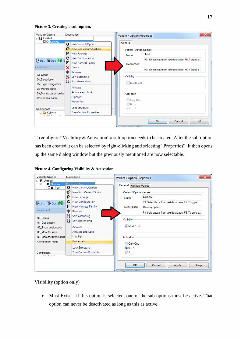
Picture 3. Creating a sub-option.
To configure “Visibility & Activation” a sub-option needs to be created. After the sub-option
has been created it can be selected by right-clicking and selecting “Properties”. It then opens
up the same dialog window but the previously mentioned are now selectable.
Picture 4. Configuring Visibility & Activation.
Visibility (option only)
Must Exist – if this option is selected, one of the sub-options must be active. That
option can never be deactivated as long as this as active.

18
Activation (option and variant)
Only one – this option specifies that the object is a variant. When active, only one
variant can be selected and active within the group.
0 … n – this option specifies the group. All options of the group can be inactive or
multiple options can be active.
1 … n – same as the previous but one option must always be active.
6.4.2 Connecting the Option to objects
The objects can be connected to the option by selecting the “Assign Options” command. The
command can be accessed several ways but the easiest is one of the following:
The “Edit” menu on the toolbar and selecting, “Assign Options”
By right-clicking an object/objects and selecting, “Assign Options”
By selecting the properties of an object/objects and selecting, “Assign Options”
No matter the choice, the same variants/options – dialog window will open. This window
will allow an option to be attached to a specific object/objects. This can be done in two
different modes, either in standard mode or enhanced mode.
Picture 5. Variants / Options - dialog window.

19
When opening the dialog window, enhanced mode will be enabled as the default option but
it can be switched between the two by selecting the other. In standard mode all available
variants/options will be shown in a list and to connect the object, simply tick the check box.
When the object is connected to an option it will change the color of the object. It will also
be shown as active in the variants/options window and under “Device Properties”, by having
the check box ticked.
Picture 6. The object has not been given an option.
Picture 7. The object has an option selected.
As mentioned before, defining variants and options to an object can be done in two modes.
Here is the difference between the two and the options available:
Standard Mode – the object is defined to the selected variants/options. This shows
all available variants/options in the project.
20
Enhanced Mode – allows for Boolean operations (AND, OR, NOT) to be included
when selecting options/variants for groups. The object can be included into a
maximum of three groups.
No matter the mode chosen, you can also:
Assign options to symbols – defining options to symbols. This means the object is
marked as an option and is also used when selecting multiple objects.
Assign options to devices – defining options to devices. Used when selecting a single
object that has multiple technical data and can only be used for variants.
Boolean operations can be included, when using the enhanced mode. This takes into
consideration that the definition (variant or option) of the object applies to the entire project
and once the definition has been selected, it cannot be changed back into an option for
standard mode. Meaning that if enhanced mode is used once in the project no further options
can be made in standard mode.
Enhanced mode has more configuration options than standard mode. These are:
Select groups – selecting which groups the option should apply to. Maximum number
of three groups.
Boolean Expression – shows the selected Boolean operations and groups.
AND, OR, NOT, brackets and the group names – the Boolean operations and the
group names. These check boxes are used to write the expressions.
Type – selecting the type. When using “Assign options to symbols” only “Object”
can be selected. Using “Assign options to devices” other types can be selected (e.g.
Component code, Attributes, Equipment, Connections, Text). Component code and
attributes can only be given variants.
Value – for the selected type a value can be entered. E.g. different component codes
can be entered to show different components.
21
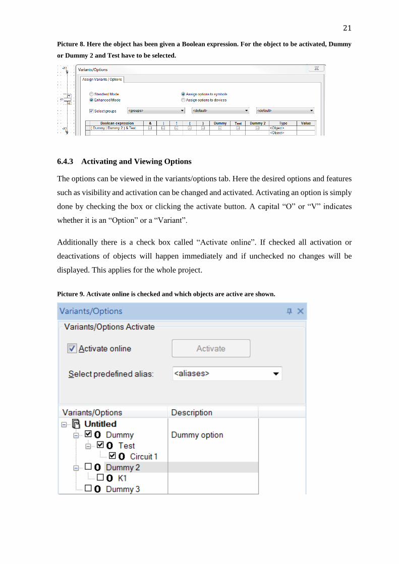
Picture 8. Here the object has been given a Boolean expression. For the object to be activated, Dummy
or Dummy 2 and Test have to be selected.
6.4.3 Activating and Viewing Options
The options can be viewed in the variants/options tab. Here the desired options and features
such as visibility and activation can be changed and activated. Activating an option is simply
done by checking the box or clicking the activate button. A capital “O” or “V” indicates
whether it is an “Option” or a “Variant”.
Additionally there is a check box called “Activate online”. If checked all activation or
deactivations of objects will happen immediately and if unchecked no changes will be
displayed. This applies for the whole project.
Picture 9. Activate online is checked and which objects are active are shown.
22
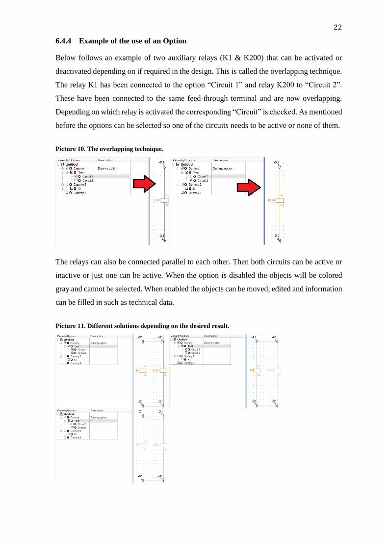
6.4.4 Example of the use of an Option
Below follows an example of two auxiliary relays (K1 & K200) that can be activated or
deactivated depending on if required in the design. This is called the overlapping technique.
The relay K1 has been connected to the option “Circuit 1” and relay K200 to “Circuit 2”.
These have been connected to the same feed-through terminal and are now overlapping.
Depending on which relay is activated the corresponding “Circuit” is checked. As mentioned
before the options can be selected so one of the circuits needs to be active or none of them.
Picture 10. The overlapping technique.
The relays can also be connected parallel to each other. Then both circuits can be active or
inactive or just one can be active. When the option is disabled the objects will be colored
gray and cannot be selected. When enabled the objects can be moved, edited and information
can be filled in such as technical data.
Picture 11. Different solutions depending on the desired result.

23
6.5 Creating Variants
Creating a variant is done in the same way as an option. In order to attach an object to a
variant it first needs to be created. This is done in the same dialog window used to create an
option. Similar as an option, variant is defined as an option group.
First a new “Option” and a sub-option needs to be created. Then “Properties” command of
the “Option” is selected. Once again the variants/options-dialog window opens up and by
ticking the “Only One” checkbox under “Activation” a variant is created. Instead of “O” in
front of the sub-option a “V” will now appear, indicating a variant.
Picture 12. Creating a variant.
The variant can be removed by selecting the desired option and clicking on the delete button.
6.5.1 Connecting a Variant to an object
The variant is connected in the same way as an option (Ch. 6.4.2). Depending on the result
either “Standard Mode” or “Enhanced Mode” is used.
Standard mode is used when an object requires a variant for the characteristics of the object.
This is done by selecting the “Device” tab in “Device properties” for the object and defining
the component code and the necessary attributes for the object. The definition has to
correspond to specific characteristics of the device. Otherwise it will not connect the variant
to the object.

24
Enhanced mode is used when an object requires a variant for the object itself. This means
that multiple objects are merged into a single object. When creating the variant for the objects
a component type has to be created under the “Type” tab in the “Assign Variants” window.
A value has to be given for the variant to know which device it should connect the variant
to. Component types have to be structurally identical, i.e. they must have the same symbols,
the same number of switching points, the same IDs etc.
Here a variant for a motor circuit breaker is attached. Enhanced mode is used and “Assign
options to devices” to indicate a variant. The group is selected for the object. Then the
“Type” is selected and the “Value” of that type is entered for the variant.
Picture 13. Attaching a variant to an object.
6.5.2 Examples of the use of a Variant
Here is an example using “Standard Mode”. A miniature circuit breaker (MCB) has been
given a variant. Depending on what the MCB is used for, the function (text description)
varies. The same component is used but in the first case it is used for the “PLC Power
Supply”. The function has been specified and the object has been attached to the variant.

25
Picture 14. Variant for the MCB used for PLC Power Supply.
This results in the MCB being activated for the “Firewall Ethernet Switch”. The only thing
changed is the function for the MCB, everything else is the same.
Picture 15. The MCB has been changed to apply for the Firewall Ethernet Switch.

26
This is an example using “Enhanced Mode”. A motor circuit breaker (Q2) has been given a
variant for the device. Depending on the technical specification the correct device can be
used. The active variant has been specified depending on the motor power (kW). It shows
that the component changes depending on which variant is active. The technical data and
type designation are changed because they are specific to the component. The symbol
appearance is the same for both components, which means the physical appearance is the
same. This would not work if the component were different in any way.
Picture 16. Depending on which variant is active, the component changes.
Picture 17. The product is the same but the components have changed, therefore different technical data.

27
6.6 Creating Packages
To create packages the view window has to be created. This is done in the same way as
opening the view window for variants and options (Ch. 6.4). The view window is given a
name and “Packages” and “Inclusive/Exclusive” are checked.
Picture 18. Creating the view window for Packages.
Creating the package is done the same way as creating a variant or option, only “New
Package” is selected. The dialog window opens and it is identical to the previous one. This
being specific to “Package Properties”. A name and description can be entered and the
package is created.
Picture 19. Creating a new package.
28
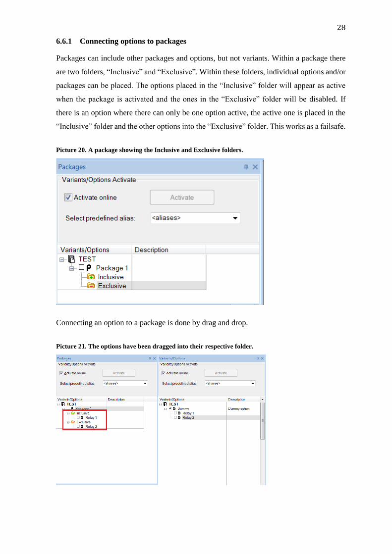
6.6.1 Connecting options to packages
Packages can include other packages and options, but not variants. Within a package there
are two folders, “Inclusive” and “Exclusive”. Within these folders, individual options and/or
packages can be placed. The options placed in the “Inclusive” folder will appear as active
when the package is activated and the ones in the “Exclusive” folder will be disabled. If
there is an option where there can only be one option active, the active one is placed in the
“Inclusive” folder and the other options into the “Exclusive” folder. This works as a failsafe.
Picture 20. A package showing the Inclusive and Exclusive folders.
Connecting an option to a package is done by drag and drop.
Picture 21. The options have been dragged into their respective folder.
29
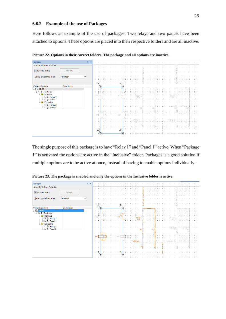
6.6.2 Example of the use of Packages
Here follows an example of the use of packages. Two relays and two panels have been
attached to options. These options are placed into their respective folders and are all inactive.
Picture 22. Options in their correct folders. The package and all options are inactive.
The single purpose of this package is to have “Relay 1” and “Panel 1” active. When “Package
1” is activated the options are active in the “Inclusive” folder. Packages is a good solution if
multiple options are to be active at once, instead of having to enable options individually.
Picture 23. The package is enabled and only the options in the Inclusive folder is active.
30
7 Creating the standard
This chapter focuses on making panel designs, circuits and PLC signals into a standard
solution.
7.1 Control panel drawings
A complete set of drawings for a control panel consists of E3 drawings, a cable list, a cable
connection list and a parts list. The E3 drawings include a list of contents, a terminal
connection list, panel design, circuits and PLC signals.
7.2 Updating the drawings
The first task that had to be done was to check if the drawings in E3 were up to date.
Unfortunately this was not the case. I received a folder containing red-pen drawings. These
red-pen drawings included information that needed updating, such as cable markings and
cable names, supply circuits, motor and engine circuits, control circuits and PLC signals,
both analog and digital.
7.3 Getting started
After completing the update of the drawings, a meeting was held with Mr. Sjöberg, to plan
the structure of the standard. The idea with the drawings was to create “Variants/Options”
for the devices used. Depending on the specifications a simple click on a variant would get
the right component without having to search for it in the component database. Also a
function where a circuit would be optional if it was not required in the drawings. “Packages”
was mentioned which could be used as a mean to sort the drawings according to specific
engine types.
A problem that Mr. Sjöberg discovered with “Packages” was that there was no way of
noticing which variants/options that were activated only by looking at the packages or the
objects. There was still another problem if a page was not required it would still exist in the
drawing as active.
The problems were first solved by creating an option named after the page number and title
of the page, and secondly, inserting a sub-option which worked as an on/off function for the
page. After this another sub-option was placed where the variants/options for the devices

31
and components were attached. Thanks to the rule of “Visibility” in the “Properties” of an
“Option”, the “Must exist” was applied to all the pages that were required. The optional
pages were not given this rule so they have to be activated manually if the customer wishes
to include them. The not required pages are simply included in the “Exclusive” folder for
the packages and that way deactivated.
Enhanced mode is used for creating all options and variants in the standard. The reason is
the Boolean expression, “Type” and “Value” command that can be found in enhanced mode.
E.g. creating a variant requires a component code. The option to include only exist in
enhanced mode. Additionally the option to turn a page on/off is only possible with enhanced
mode.
The standard was split into six main options, “Panel design, Circuits, Digital inputs, Digital
outputs, Analog inputs and Analog outputs”. “Panel design” include the options such as front
view, back view, M-unit plate etc. The “Circuit” option include all circuits and objects for
supply, pump motor, heating, ventilation, control etc. The rest of the options are for PLC
signals.
Picture 24. The main options for the standard.
7.4 Panel design
The “Panel design” option includes all pages for the design. It consists of options. The
standard measurements for creating a BJA-panel are 800mm or 1200mm in width, so these
are the two possibilities on the drawings. A couple of pages can contain the two possibilities
on the same page but mostly they are on separate pages. The pages with the two possibilities
are placed in the same sub-option and the whole page is made into an option. These pages
are required, that means the “Must Exist” checkbox under “Visibility” is checked. Since one
of the panels also has to be active the “1 … n” under “Activation” is checked. “Only One”
cannot be used since that is for variants, and variants can only be done for a single object.

32
Some pages only have an on/off option independent of the two possibilities selected. The
“Must Exist” checkbox is also applied to these pages. A problem with the “Inside view”
pages occurred, and no option could be done for these pages. They are therefore not part of
the “Panel design” option and must be managed manually. The reason is explained in Ch.
9.2 Improvements. An example with the two possibilities on the same page can be found in
Appendix 1.
Picture 25. The options for Panel design. The grayed out checkboxes indicate the must exist rule. A short
description is also given.
7.5 Circuits
This main option includes both variants/options. This shows the true potential of this
function. Here the options are either named by the page number and page title or only by the
page title. The reason for this is that some pages have multiple circuits on the same page that
are optional depending on the engine type. Other pages have the same title but are split on
multiple pages. Therefore these options were only given the title name of the option and then
the sub-options were given the title name and page number. These pages only include
options. The page name is displayed when including the pages into packages.
The structure of this main option can be divided into three different sets. To get a better
understanding look at Appendix 2, while reading the following:

33
Options set – this set only includes options and is used when separate circuits on a
page need to be activated depending on if it is required or not. It contains an activate
option (the first sub-option), which is connected to the page. Some have another sub-
option that is used to activate a certain circuit on the page. An example can be found
in Appendix 3
Variant set – this set includes both variants/options. The option is used to activate
the page. The variant is attached on one or more component and have a specific
component code attached to it. These variants are chosen to fit according to technical
data. Appendix 4 gives an example.
Activation set – this set only includes options and is used when multiple pages have
similar names and functions. The first sub-option has a merged name for the multiple
pages. Then the sub-options have the page number and the specific name and that
option is used to activate the page.
As in the previous chapter, these options and variants have been given different properties.
Some have the “Must Exist” checked and “Activation” has different options selected
depending on the requirement.
7.6 PLC signals
PLC signals are split into four groups since there are many signals and a lot of options. It
was easier to keep track when splitting them into smaller groups. No variants were used for
the signals.
7.6.1 Digital input
Appendix 5 contains the list of options. The digital input signals that belong the “ALL”
engine types were made into an option. The input module was attached to the option for the
“ALL” signals since they do not need to be moved if there are spare signals.
Engine specific digital input signals that are attached to an external panel were made into an
option. E.g. all prelube oil pump signals that go to the same panel were attached to one
option. For the engine specific signals only the circuit going to and from the external panel
were made into an option. The input module was not attached since if the signal is not
required another signal could replace it. The structure of the options is the same as in
previous chapters. Appendix 6 contains the two options.
34
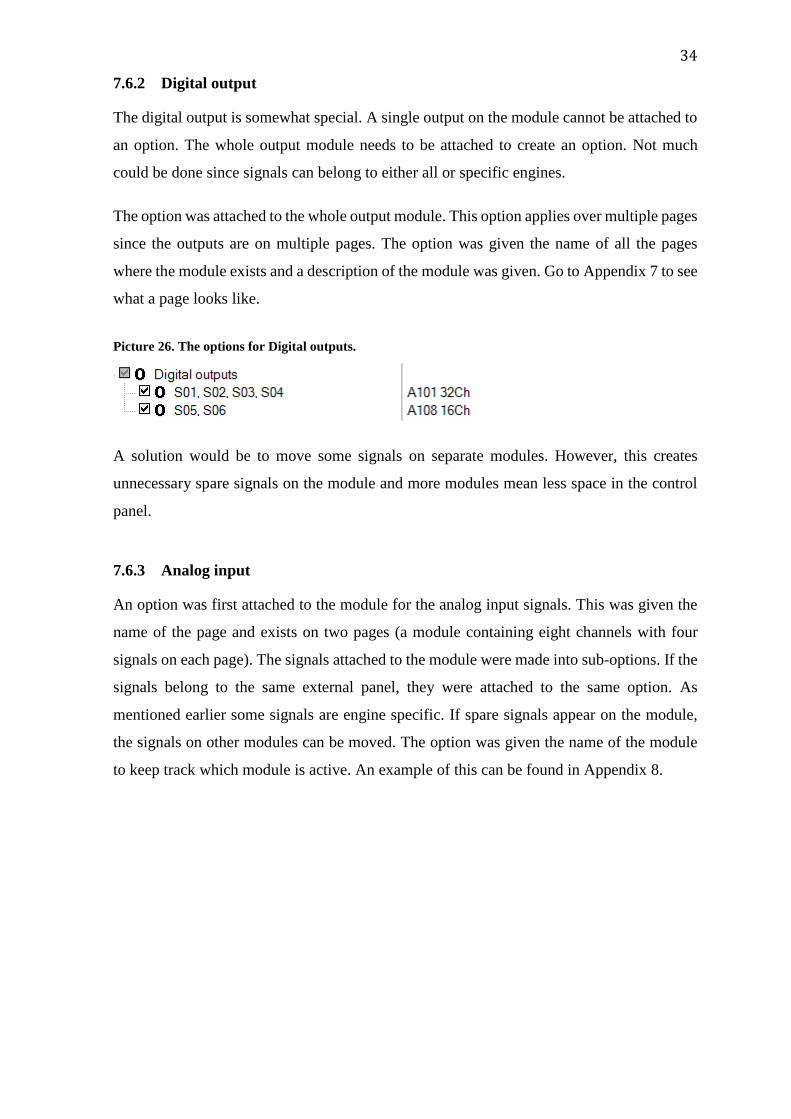
7.6.2 Digital output
The digital output is somewhat special. A single output on the module cannot be attached to
an option. The whole output module needs to be attached to create an option. Not much
could be done since signals can belong to either all or specific engines.
The option was attached to the whole output module. This option applies over multiple pages
since the outputs are on multiple pages. The option was given the name of all the pages
where the module exists and a description of the module was given. Go to Appendix 7 to see
what a page looks like.
Picture 26. The options for Digital outputs.
A solution would be to move some signals on separate modules. However, this creates
unnecessary spare signals on the module and more modules mean less space in the control
panel.
7.6.3 Analog input
An option was first attached to the module for the analog input signals. This was given the
name of the page and exists on two pages (a module containing eight channels with four
signals on each page). The signals attached to the module were made into sub-options. If the
signals belong to the same external panel, they were attached to the same option. As
mentioned earlier some signals are engine specific. If spare signals appear on the module,
the signals on other modules can be moved. The option was given the name of the module
to keep track which module is active. An example of this can be found in Appendix 8.

35
Picture 27. The options for Analog inputs.
7.6.4 Analog output
The analog output options are structurally the same as the analog input. The first option is
attached to the module and then the external signals are made into sub-options. These signals
only exist for specific engines so they all have separate options. An example of this can be
found in Appendix 9.
Picture 28. The options for Analog outputs

36
8 Configuration – Attaching the Options to Packages
The standard includes packages for all engine types and modifications. This thesis however,
presents three packages or engine types. These include the standards for two dual fuel
engines and one gas engine. These engines use different kinds of fuel and include different
modules as well.
On certain pages a box with the text “ALL” or numbers can be found. These indicate which
engine type the circuits/components belongs to. If the option for the circuits/components
belongs to that engine type, the option is selected and dragged into the “Inclusive” folder.
An option not belonging to the engine type is dragged into the “Exclusive” folder in order
to avoid the option being accidentally activated.
Picture 29. The packages that are presented in this Bachelor's thesis.
These packages include all the options for the main options (panel design, circuits and PLC
signals). The options that are optional for all engines types are included in the “Inclusive”
folder. Variants as mentioned in Ch. 6.6.1 cannot be attached to a package so choosing
between variants needs to be done manually. In Appendix 10 a package has been selected
and every option belonging to that package has been activated.

37
9 Results
The result of this Bachelor’s thesis was to create a functioning standard solution for control
panels that the department can use for manufacturing, is easy to use and reduces working
hours. This is achieved. The first part of this thesis was to figure out which solution would
fit the department best, and the solution chosen is the best fit.
The second part was to create the standard itself and this is done. By clicking on the package
for the wanted engine type, all circuits and components to that specific engine is activated.
Some issues have been found but a solution is either being discussed or in development.
A simple explanation of the procedure to create the control panel is:
The specific package is selected from the “Packages” view window
The optional pages, circuits and signals are activated or deactivated in the
“Variants/Options” view window
The correct variant for components and devices is selected in the “Variants/Options”
view window according to technical specifications. Some components require
manual modification.
Project specific information is filled in, changes or movement of text, circuits and
components are made.
9.1 Testing
The testing of the standard has so far been done by me. A meeting is going to be held where
the department will get the opportunity to test the standard and give their opinions. During
the testing phase, some bugs/problems where found:
Feed-trough terminals attached to multiple options would only activate on one
option. This was sorted out.
The wiring between feed-through terminals might disappear if they lead to different
external panels. The wiring then needs to be connected manually.
Reference points between pages such as feeding voltage signals need to be changed
manually to lead to the correct page.

38
An inactive device will still show up in the parts list. A solution would be to create a
script that removes the device from the database.
An inactive page appears when creating a .pdf file. The suggested solution is to
remove the page manually or to create a script. This is to be discussed with Mr.
Lindberg.
There might be other bugs in the standard, but they are well hidden. The department test will
probably reveal some of these bugs.
9.2 Problems & Improvements
This chapter focuses on the problems that have been discovered during the creation of the
standard and what might be done to fix them.
A variant cannot be made if there is a physical difference in the appearance of two
devices. E.g. if the physical device is placed in between devices in the drawing and
the variant is bigger than the physical device. Why not give a pop-up indication that
the component has to be inserted again?
Dummy textboxes cannot be attached to a variant or option. It would appear as if the
text was attached but when selecting different variants the text is still visible. The
problem is unsolved.
As mentioned in Ch. 7.4, “Inside view” in “Panel design”. These pages cannot be
attached to an option. There are a great number of objects on the pages. These are
used on other pages and attached to multiple options. In order to attach all the objects
to the page, all previous options used for those objects needs to be included in the
group as well. “Enhanced Mode” can only include three groups. This made it
impossible to attach all objects on the page. A solution might be to use “Standard
Mode. Another would be to remove all the inserted objects, but having to reinsert
them.

39
10 Discussion
This thesis covers a wide area. Everything from figuring out the best solution, purpose, the
approach, how to create and use the functions, the solution itself and finally the result. The
size of the work for this thesis has felt somewhat overwhelming but in the end I think that
the experience gained has made it worth it.
I received the thesis in the autumn of 2016 and had a lot of time to spend on it. I used the
time to figure out which solution would be the best fit and had meetings and discussions
with Mr. Lindberg. He helped with explaining how the solutions worked and what it could
be used for. Around this time I started working on the solution chosen. As time went by my
hours became limited. Both because of a busy school schedule and taking on more projects
from the employer of this thesis. I was employed part time.
At the beginning of 2017 most of my time was spent on learning how the functions worked.
It took a long time since there was basically no experience within the department on the
functionality. I received a short instruction manual from Mr. Lindberg. The E3.series online
documentation was of some help. There was no information online on the functions. The
learning process has mostly been achieved by trial and error.
Early spring I put a great number of hours into this thesis. The knowledge I received
sometimes ended up in me doing a task all over again because a different way of doing it
was found.
Much time was spent on updating the E3 drawings. There is a constant flow of updates to
these drawings and that is just part of it. It takes time to update the drawings, both easier and
harder. At the moment I am the only one with the knowledge of how to update the new
standard.
My supervisor, Mr. Tom Aura, read Ch. 6 where I introduced and explained the functions.
He saw the potential of these functions and mentioned the time-consuming updates.
Furthermore, he suggested that with the experience gained, a sit down with all the design
engineers. This to figure out the best usage of these functions and how the drawings are
structurally built up to get the best result.
I consider the standard solution created a first draft. I suggest a second draft to be made with
the knowledge gained with the help of the other design engineers. This would create an
improved and smarter standard.

40
With a smarter standard I mean the possibility to connect the main options with each other.
A simple click on an option would activate the component, circuit and signals throughout
the drawings. E.g. activating prelube oil motor would activate the circuits and the signals
belonging to it.
I have learned a lot working on this thesis. The process of coming up with a solution and
getting it working has been rewarding. To do something with no experience, having to learn
it and finally having cutting edge expertise in the subject has been a useful journey and
experience. It has also improved my ability to discuss the subject with others to get a
different point of view and therefore a better solution.

41
11 Bibliography
ABB, 2016. ABB Group - Leading digital technologies for industry. [Online] Available at: http://new.abb.com/news/detail/222/abb-next-stage-of-unlocking-value [Accessed 2 January 2017].
ABB, 2017. ABB - Yksiköt Suomessa. [Online] Available at: http://new.abb.com/fi/abb-lyhyesti/suomessa/yksikot [Accessed 2 January 2017].
ABB, 2017. ABB Oy, Power Generation. [Online] Available at: http://new.abb.com/fi/abb-lyhyesti/suomessa/yksikot/power-generation [Accessed 3 January 2017].
ABB, 2017. ABB Suomessa. [Online] Available at: http://new.abb.com/fi/abb-lyhyesti/suomessa [Accessed 2 January 2017].
CIM-TEAM, n.d. Koulutusmateriaali: Moduuli 8, s.l.: s.n.
Gawlowski, R., 2010. Liquid-Cooled diesel Engines. In: On-Site Power Generation. s.l.:s.n.
Wärtsilä, 2014. Liquid fuel power plants. [Online] Available at: http://cdn.wartsila.com/docs/default-source/Power-Plants-documents/liquid-fuel-power-plants-2014.pdf?sfvrsn=0 [Accessed 28 January 2017].
Wärtsilä, 2016. Gas & Multi-fuel Power Plants Brouchure. [Online] Available at: http://cdn.wartsila.com/docs/default-source/Power-Plants-documents/downloads/brochures/gas-and-multi-fuel-power-plants-2016.pdf?sfvrsn=2 [Accessed 28 January 2017].
Wärtsilä, 2017. Gas power plants. [Online] Available at: http://www.wartsila.com/energy/solutions/gas-power-plants [Accessed 28 January 2017].
Wärtsilä, 2017. Liquid fuel power plants. [Online] Available at: http://www.wartsila.com/energy/solutions/liquid-fuel-power-plants [Accessed 28 January 2017].
Wärtsilä, 2017. Multi-fuel power plants. [Online] Available at: http://www.wartsila.com/energy/solutions/multi-fuel-power-plants [Accessed 28 January 2017].
Zuken Inc., 2017. Zuken, Our History. [Online] Available at: http://www.zuken.com/en/company/corporate/history [Accessed 12 January 2017].
Zuken, 2015. E3.series Online Documentation, s.l.: s.n.

42
Zuken, 2016. E3.series - Electrical Wiring, Control Systems and Fluid Engineering Software, s.l.: Zuken .
List of Appendices
Appendix 1 – An example of the two possibilities (800mm and 1200mm) on the same page
for panel design. The 800mm option is active and as indicated by the yellow color.
Appendix 2 – A list with all the Variants/Options used for engine and motor circuits.
Appendix 3 – An example of the Options set. Some circuits are active and showing that they
belong to different sub-options.
Appendix 4 – Use of the Variant set. Components has been given a variant and if manual
modification is required, the component code can be found in the textbox.
Appendix 5 – A list of all the options for “Digital Input” signals.
Appendix 6 – Example of the difference between “ALL” engine signals and specific engine
signals.
Appendix 7 – A page for “Digital Output” signals. The module is the option and include
both “ALL” and specific signals.
Appendix 8 – An example page for the use of “Analog Input” signals. The module is an
option and the external panels are made into a sub-option.
Appendix 9 – “Analog Output” signals. These have the same structure as “Analog Output”.
Appendix 10 – Package 20 is selected and all options belonging to the package is activated.