e-yantra robotics competition 2014-15 report by e … · e-yantra robotics competition – 2014-15...
TRANSCRIPT

1
e-Yantra Robotics Competition – 2014-15
REPORT
By E-yantra Team
Team id :- e-yrc #354-WM
Team Leader :- Saksham Srivastava
Team members:-
1. Shubham Anand
2. Rajat Kumar Soni
3. Rashmi Singh
DEPARTMENT OF ELECTRONICS & COMMUNICATION ENGINEERING
JSS ACADEMY OF TECHNICAL EDUCATION
C-20/1 SECTOR-62, NOIDA

2
Name E-mail Contact Branch Year
Saksham Srivastava
[email protected] 07503900271 Electronics And Communication Engineering
3rd
Shubham Anand
[email protected] 08750017445 Electronics And Communication Engineering
3rd
Rajat Kumar Soni
[email protected] 09452688788 Electronics And Communication Engineering
3rd
Rashmi Singh
[email protected] 08588936053 Electronics And Communication Engineering
3rd

3

4

5

6

7
SCORE CARD
# Task Name
Marks Obtained
(A) Penalty
(B) Final Marks
(A+B) Remarks
1 Task 0 - Flex Printing
Task 0 Accepted Great Job !
2 Task 1 - Theme Analysis
53/60 0 53/60 Great Job ! Keep it up
3 Task 2 - Implementation
Analysis
116/125 0 116/125 Good Job. Keep it up.
4 Task 3 - Video Demo Submission
For Original Configuration
945 0 945 Very good mechanism. Creative Marks Distribution Graph
For Bonus Configuration
885 0 (20% of score (A) is used to calculate the
final score(B)) 177
Very good mechanism.
Creative
5 Task 4 - Documented Code
Submission 60
60 0 60 Good work
8
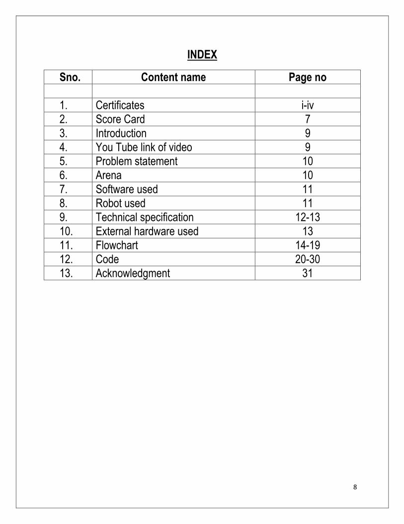
INDEX
Sno. Content name Page no
1. Certificates i-iv
2. Score Card 7
3. Introduction 9
4. You Tube link of video 9
5. Problem statement 10
6. Arena 10
7. Software used 11
8. Robot used 11
9. Technical specification 12-13
10. External hardware used 13
11. Flowchart 14-19
12. Code 20-30
13. Acknowledgment 31

9
E-yantra robotics competition is organized by IIT Mumbai and it’s supported by
MHRD. This year over 3400 teams registered out of which 260 teams were
qualified for next level. Clearing and completing different tasks and challenges 6
teams per theme are selected for the finale which was held at IIT-Bombay.
Our hard work, dedication and perseverance has made us qualified for the top 6
finale. In task 3 that was video demonstration of the problem solution we have the
highest marks among all the teams participated all over India. In the finale we were
at 5th position.
Theme:- Warehouse management
Introduction
Warehouse management system is vital in storage and movement of goods. On-
line purchasing has gained tremendous popularity among people of all generations
and this entails receiving orders, packaging, transportation, storage and shipment.
Goods are packaged in cartons of defined sizes -- received, stored and shipped
from a warehouse. Given that storage is vital in the supply chain, optimizing
storage space through proper placement of packages such that movement of
packages is minimized is the key. Automating the process of receiving the
packages, placing them in correct locations in the warehouse reduces manual labor
and avoids damage to the packages.
Keeping with the importance of this subject, in e-Yantra Robotics Competition
2014 (eYRC-2014), one of the themes chosen was warehouse management. In this
theme, we focus on automating the task of placing the packages in designated
locations in the warehouse. The theme design represents a simplified warehouse
having 12 pick-up points where packages arrive. We use different colored blocks
to represent three types of packages. There are five deposition zones, each
designated for deposition of a particular type of package. The robot has to visit
each pick-up point and if there is a valid package(red , blue or green ) pick up the
package and don’t pick up the invalid package(black color package). The robot
detects the color of the package using a color sensor provided and places it in the
appropriate deposition zone.
YouTube link of the video:-
1. http://youtu.be/Q12QuPvdV5s ----task 3 video
2. http://youtu.be/W4JaAQ8lx-I----- bonus task video

10
Problem statement
Make an autonomous robot that performs the following tasks:
1. The robot starts from START position of the arena representing a warehouse
Thermocol blocks are used to represent packages. Three colors Red (R),
Blue (B), or Green (G) are used to represent different types of packages.
There are twelve pick-up points in the warehouse where packages are
placed on arrival to the warehouse. Each pick-up point can contain: (i) No
package – when the pick-up point is empty (ii) Valid package – when a
package of one of the colors – Red (R), Blue (B), or Green (G) – is at the
pick-up point or (iii) Invalid package – when a Black package is at the
pick-up point which should not be picked up. Number of valid packages to
be picked up from the pick-up points can vary from 3 to 7.
There are five Deposition Zones numbered 1 to 5. Each deposition zone has
an associated color – only packages of that color can be deposited in that
deposition zone. A deposition table (explained in Section 6: Theme rules)
provides the information on the designated color for each deposition zone.
For example, if deposition zones 1 and 2 are designated as R, only red
packages can be deposited in these deposition zones. Each deposition zone
can take a maximum of 2 packages only.
2. The robot traverses the path around the warehouse and does the following:
Checks pick-up point for a package.
If the package is Invalid, sounds a buzzer and moves on.
If the package is Valid, does the following:
1. Indicates the color of the package by turning on the appropriate color in the
RGB Light Emitting Diode (LED) provided with the kit.
2. Picks up the package and deposits it in the appropriate deposition zone.
Robot repeats the above protocol till it picks up and deposits all the valid
packages on the arena.
After depositing the last package at the appropriate zone, the robot sounds
the buzzer continuously.
Sound of the continuous buzzer indicates END of task.
ARENA
The arena for this theme is a simplified abstraction of a warehouse. There are 12
pick-up points marked on the arena. Packages of different types represented by

11
blocks of colors Red, Blue, or Green will be placed on these pick-up points. A
pick-up point may or may not contain a package. For example, with reference to
Figure 1, there are 2 red blocks, 3 blue blocks, and 2 Green blocks placed on the
pick-up points. There are three black blocks that are invalid packages and two
pick-up points are empty. The deposition zones are indicated by 1, 2, 3, 4, and 5 in
the arena. The black line on the arena is the line along which the robot will
navigate its path.
ARENA
Software used:- Atmel Studio 6.0
Robot used :- Fire Bird V ATMEGA 2560

12
Technical specification of Robot:-
1. Microcontroller:
i. Atmel ATMEGA2560 as Master microcontroller (AVR architecture
based Microcontroller)
ii. Atmel ATMEGA8 as Slave microcontroller (AVR architecture based
Microcontroller)
2. Sensors:
i. Three white line sensors (extendable to 7)
ii. Five Sharp GP2Y0A02YK IR range sensor (One in default
configuration)
iii. Eight analog IR proximity sensors
iv. Two position encoders (extendable to four)
v. Battery voltage sensing
vi. Current Sensing (Optional)
vii. Five Max Botix Ultrasonic Range Sensors (Optional)
3. Indicators:
i. 2 x 16 Characters LCD
ii. Buzzer and Indicator LEDs
4. Control:
i. Autonomous Control
ii. PC as Master and Robot as Slave in wired or wireless mode
5. Communication:
i. USB Communication
ii. Wired RS232 (serial) communication
iii. Wireless ZigBee Communication (2.4GHZ) (if XBee wireless module
is installed)
iv. Wi-Fi communication (if Wi-Fi module is installed)
v. Bluetooth communication (if Bluetooth wireless module is installed)
vi. Simplex infrared communication (From infrared remote to robot)
6. Dimensions:
i. Diameter: 16cm
ii. Height: 8.5cm
iii. Weight: 1100gms
7. Power:
i. 9.6V Nickel Metal Hydride (NiMH) battery pack and external
Auxiliary power from battery charger.
ii. On Board Battery monitoring and intelligent battery charger.

13
8. Battery Life:
2 Hours, while motors are operational at 75% of time
9. Locomotion:
i. Two DC geared motors in differential drive configuration and caster wheel
at front as support
ii. Top Speed: 24 cm / second
iii. Wheel Diameter: 51mm
iv. Position encoder: 30 pulses per revolution
External Hardware used :-
1. Color Sensor :- Color sensor is a type of sensor that senses the color of a
particular wavelength or frequency from an external environment by using
Frequency to voltage conversion .
2. SERVO MOTOR
A servomotor is a rotatory actuator that allows for precise control of angular
position, velocity and acceleration.

14
FLOWCHART:-
FLOWCHART FOR MOVEMENT OF ROBOT

15
FLOWCHART FOR DETECTION OF PACKAGE

16
FLOWCHART FOR PUTTING THE PACKAGE

17
FLOWCHART FOR PUTTING THE PACKAGE

18
FLOWCHART FOR PUTTING THE PACKAGE

19
SUMMARY OF THE FLOWCHART:-
1) At the 1st check point for the very first time the robot will take a left turn.
2) But after then it will never take a left turn at 1st check point.
3) It reaches the next check point.
4) It will check for the presence of package.
5) If the package is present and is valid i.e. color of the package is RED, BLUE
or GREEN then the corresponding LED will glow otherwise it will move to
next check point.
6) The value of R or B or G will be increased by 1 which was initially set to 0.
7) The robotic arm will pick the package.
8) And as per the deposition table given to us it will follow the shortest path to
that deposition zone & put the package there.
9) If the deposition zone is filled with 2 packages already then it will go to the
next deposition zone as per the deposition table.
10) If the color of package is black means package is invalid, it will sound
the buzzer for 1 second & move forward for the next check point.
11) The above process will continue until all the packages are placed at
their corresponding deposition zone.
12) When all the packages are kept at their corresponding zone then the
buzzer will sound continuously, hence indicting the task has been
completed.
DEPOSITION TABLE
SNO. TYPE OF PACKAGE NUMBER OF
PACKAGE
DESIGNATED
DEPOSITION
ZONE (X)
1. RED (R) Will be given as
per the problem
statement.
1 OR 3 OR 10 OR
12 OR 14 OR 21
(Exact value will be
given as per the
problem statement).
2. BLUE (B) do do
3. GREEN (G) do do

20
Code:-
For I/O interfacing
#define F_CPU 14745600
#include <avr/io.h>
#include <avr/interrupt.h>
#include <util/delay.h>
//Function to initialize Buzzer
void buzzer_pin_config (void)
{
DDRC = DDRC | 0x08; //Setting PORTC 3 as outpt
PORTC = PORTC & 0xF7; //Setting PORTC 3 logic low to turnoff buzzer
}
//Function to configure Interrupt switch
void interrupt_switch_config (void)
{
DDRE = DDRE & 0x7F; //PORTE 7 pin set as input
PORTE = PORTE | 0x80; //PORTE7 internal pull-up enabled
}
//Function to configure LDD bargraph display
void LED_bargraph_config (void)
{
DDRJ = 0xFF; //PORT J is configured as output
PORTJ = 0x00; //Output is set to 0
}
//Function to Initialize PORTS
void port_init (void)
{

21
buzzer_pin_config();
interrupt_switch_config();
LED_bargraph_config();
}
void buzzer_on (void)
{
unsigned char port_restore = 0;
port_restore = PINC;
port_restore = port_restore | 0x08;
PORTC = port_restore;
}
void buzzer_off (void)
{
unsigned char port_restore = 0;
port_restore = PINC;
port_restore = port_restore & 0xF7;
PORTC = port_restore;
}
void init_devices (void)
{
cli(); //Clears the global interrupts
port_init();
sei(); //Enables the global interrupts
}
//Main Function
int main(void)
{
init_devices();

22
while(1)
{
if((PINE & 0x80) == 0x80) //switch is not pressed
{
buzzer_off(); //Turn off buzzer
PORTJ = 0x00; //Turn off bargraph LEDs
}
else
{
buzzer_on(); //Turn on buzzer
PORTJ = 0xFF; //Turn on bargraph LEDs
}
}
}
Motion control---
#define F_CPU 14745600
#include <avr/io.h>
#include <avr/interrupt.h>
#include <util/delay.h>
void motion_pin_config (void)
{
DDRA = DDRA | 0x0F; //set direction of the PORTA 3 to PORTA 0 pins as output
PORTA = PORTA & 0xF0; // set initial value of the PORTA 3 to PORTA 0 pins to logic 0
DDRL = DDRL | 0x18; //Setting PL3 and PL4 pins as output for PWM generation
PORTL = PORTL | 0x18; //PL3 and PL4 pins are for velocity control using PWM
}
23
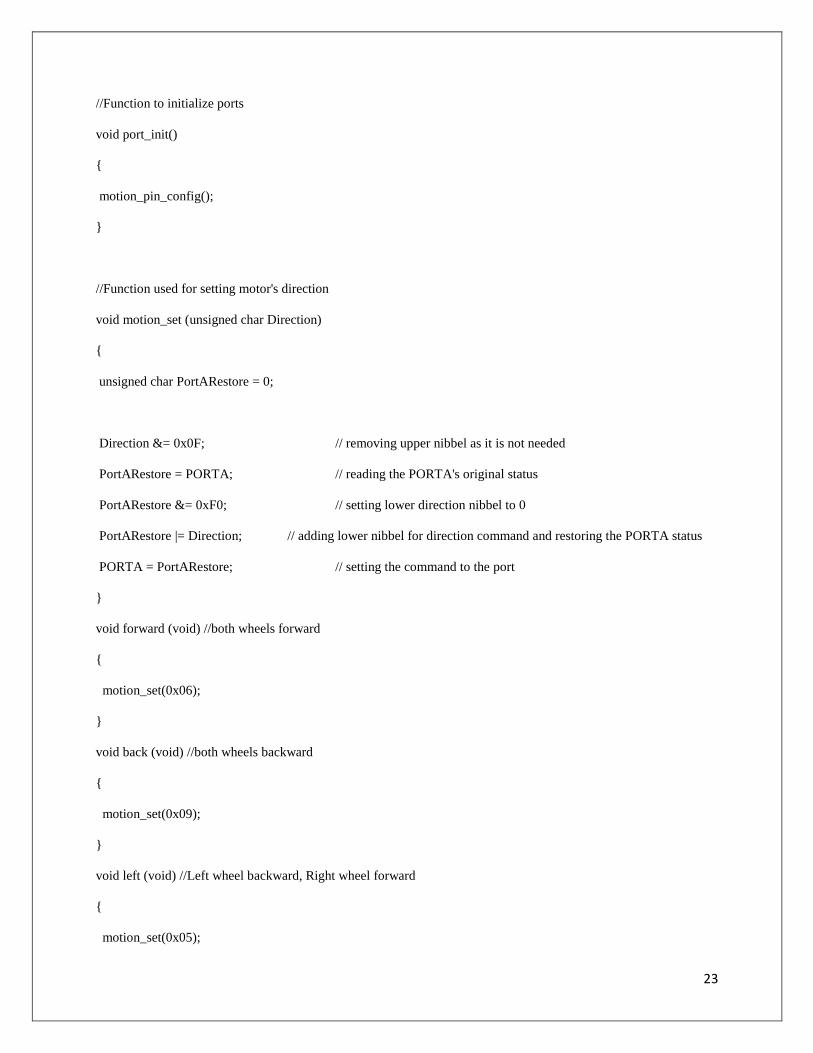
//Function to initialize ports
void port_init()
{
motion_pin_config();
}
//Function used for setting motor's direction
void motion_set (unsigned char Direction)
{
unsigned char PortARestore = 0;
Direction &= 0x0F; // removing upper nibbel as it is not needed
PortARestore = PORTA; // reading the PORTA's original status
PortARestore &= 0xF0; // setting lower direction nibbel to 0
PortARestore |= Direction; // adding lower nibbel for direction command and restoring the PORTA status
PORTA = PortARestore; // setting the command to the port
}
void forward (void) //both wheels forward
{
motion_set(0x06);
}
void back (void) //both wheels backward
{
motion_set(0x09);
}
void left (void) //Left wheel backward, Right wheel forward
{
motion_set(0x05);
24
}
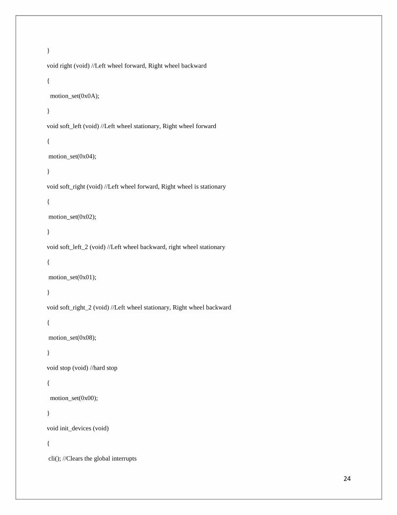
void right (void) //Left wheel forward, Right wheel backward
{
motion_set(0x0A);
}
void soft_left (void) //Left wheel stationary, Right wheel forward
{
motion_set(0x04);
}
void soft_right (void) //Left wheel forward, Right wheel is stationary
{
motion_set(0x02);
}
void soft_left_2 (void) //Left wheel backward, right wheel stationary
{
motion_set(0x01);
}
void soft_right_2 (void) //Left wheel stationary, Right wheel backward
{
motion_set(0x08);
}
void stop (void) //hard stop
{
motion_set(0x00);
}
void init_devices (void)
{
cli(); //Clears the global interrupts
25
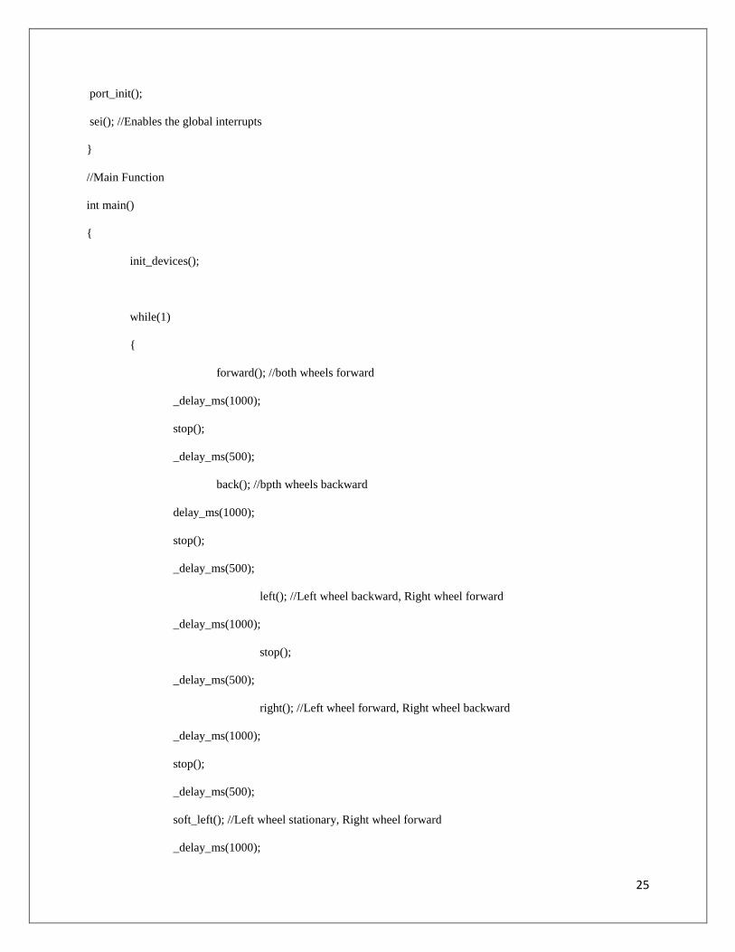
port_init();
sei(); //Enables the global interrupts
}
//Main Function
int main()
{
init_devices();
while(1)
{
forward(); //both wheels forward
_delay_ms(1000);
stop();
_delay_ms(500);
back(); //bpth wheels backward
delay_ms(1000);
stop();
_delay_ms(500);
left(); //Left wheel backward, Right wheel forward
_delay_ms(1000);
stop();
_delay_ms(500);
right(); //Left wheel forward, Right wheel backward
_delay_ms(1000);
stop();
_delay_ms(500);
soft_left(); //Left wheel stationary, Right wheel forward
_delay_ms(1000);

26
stop();
_delay_ms(500);
soft_right(); //Left wheel forward, Right wheel is stationary
_delay_ms(1000);
stop();
_delay_ms(500);
soft_left_2(); //Left wheel backward, right wheel stationary
_delay_ms(1000);
stop();
_delay_ms(500);
soft_right_2(); //Left wheel stationary, Right wheel backward
_delay_ms(1000);
stop();
_delay_ms(1000);
}
}
For interfacing servo motor
#define F_CPU 14745600
#include <avr/io.h>
#include <avr/interrupt.h>
#include <util/delay.h>
//Configure PORTB 5 pin for servo motor 1 operation
void servo1_pin_config (void)
{
DDRB = DDRB | 0x20; //making PORTB 5 pin output
PORTB = PORTB | 0x20; //setting PORTB 5 pin to logic 1
}
//Configure PORTB 6 pin for servo motor 2 operation

27
void servo2_pin_config (void)
{
DDRB = DDRB | 0x40; //making PORTB 6 pin output
PORTB = PORTB | 0x40; //setting PORTB 6 pin to logic 1
}
//Configure PORTB 7 pin for servo motor 3 operation
void servo3_pin_config (void)
{
DDRB = DDRB | 0x80; //making PORTB 7 pin output
PORTB = PORTB | 0x80; //setting PORTB 7 pin to logic 1
}
//Initialize the ports
void port_init(void)
{
servo1_pin_config(); //Configure PORTB 5 pin for servo motor 1 operation
servo2_pin_config(); //Configure PORTB 6 pin for servo motor 2 operation
servo3_pin_config(); //Configure PORTB 7 pin for servo motor 3 operation
}
//TIMER1 initialization in 10 bit fast PWM mode
//prescale:256
// WGM: 7) PWM 10bit fast, TOP=0x03FF
// actual value: 52.25Hz
void timer1_init(void)
{
TCCR1B = 0x00; //stop
TCNT1H = 0xFC; //Counter high value to which OCR1xH value is to be compared with
TCNT1L = 0x01; //Counter low value to which OCR1xH value is to be compared with
OCR1AH = 0x03; //Output compare Register high value for servo 1

28
OCR1AL = 0xFF; //Output Compare Register low Value For servo 1
OCR1BH = 0x03; //Output compare Register high value for servo 2
OCR1BL = 0xFF; //Output Compare Register low Value For servo 2
OCR1CH = 0x03; //Output compare Register high value for servo 3
OCR1CL = 0xFF; //Output Compare Register low Value For servo 3
ICR1H = 0x03;
ICR1L = 0xFF;
TCCR1A = 0xAB; /*{COM1A1=1, COM1A0=0; COM1B1=1, COM1B0=0; COM1C1=1 COM1C0=0}
For Overriding normal port functionality to OCRnA outputs.
{WGM11=1, WGM10=1} Along With WGM12 in TCCR1B for Selecting
FAST PWM Mode*/
TCCR1C = 0x00;
TCCR1B = 0x0C; //WGM12=1; CS12=1, CS11=0, CS10=0 (Prescaler=256)
}
//Function to initialize all the peripherals
void init_devices(void)
{
cli(); //disable all interrupts
port_init();
timer1_init();
sei(); //re-enable interrupts
}
//Function to rotate Servo 1 by a specified angle in the multiples of 1.86 degrees
void servo_1(unsigned char degrees)
{
float PositionPanServo = 0;
PositionPanServo = ((float)degrees / 1.86) + 35.0;
OCR1AH = 0x00;

29
OCR1AL = (unsigned char) PositionPanServo;
}
//Function to rotate Servo 2 by a specified angle in the multiples of 1.86 degrees
void servo_2(unsigned char degrees)
{
float PositionTiltServo = 0;
PositionTiltServo = ((float)degrees / 1.86) + 35.0;
OCR1BH = 0x00;
OCR1BL = (unsigned char) PositionTiltServo;
}
//Function to rotate Servo 3 by a specified angle in the multiples of 1.86 degrees
void servo_3(unsigned char degrees)
{
float PositionServo = 0;
PositionServo = ((float)degrees / 1.86) + 35.0;
OCR1CH = 0x00;
OCR1CL = (unsigned char) PositionServo;
}
{
OCR1AH = 0x03;
OCR1AL = 0xFF; //Servo 1 off
}
void servo_2_free (void) //makes servo 2 free rotating
{
OCR1BH = 0x03;
OCR1BL = 0xFF; //Servo 2 off
}
void servo_3_free (void) //makes servo 3 free rotating

30
{
OCR1CH = 0x03;
OCR1CL = 0xFF; //Servo 3 off
}
//Main function
void main(void)
{
unsigned char i = 0;
init_devices();
for (i = 0; i <90; i++)
{
servo_1(i);
_delay_ms(30);
servo_2(i);
_delay_ms(30);
servo_3(i);
_delay_ms(30);
}
_delay_ms(2000);
servo_1_free();
servo_2_free();
servo_3_free();
while(1);
NOTE:- It’s a sample code(exact code can not be reproduced here) that is for the reference and
help. For exact code please refer the team members.

31
Acknowledgement:-
This project consumed huge amount of work, research and dedication. Still,
implementation would not have been possible if we did not have a support of many
individuals and organizations. Therefore we would like to extend our sincere
gratitude to all of them.
We would like to express our special thanks of gratitude to our mentors Ms.
GAYATRI SAKYA and Mr. PRASAD M. who gave us the golden opportunity
to participate in this wonderful competition. They also helped us in doing a lot of
research and we came to know about so many new things.
Secondly we would also like to thank our parents, friends and teachers who helped
me a lot in finalizing this project within the limited time frame and supported
technically ,non technically and morally in the best possible manner they can.
Last but not the least we are thankful to E-yantra for their competition. For
providing the robot and for providing necessary guidance concerning the
implementation.