Ê1 /9 Ê /, -/, / fitzgerald, p.e. chief engineer adopted by harris county commissioners court ......
TRANSCRIPT

Adopted October 2004 Updated December 2010
HARRIS COUNTYFLOOD CONTROL
DISTRICT

POLICY, CRITERIA, AND PROCEDURE MANUAL
FOR APPROVAL AND ACCEPTANCE OF
INFRASTRUCTURE
Submitted by: Arthur L. Storey, Jr., P.E. Executive Director, PID
Michael D. Talbott, P.E. Director
Steve Fitzgerald, P.E. Chief Engineer
Adopted by Harris County Commissioners Court
Ed Emmett County Judge
El Franco Lee Steve Radack Commissioner, Precinct 1 Commissioner, Precinct 3
Sylvia R. Garcia Jerry Eversole Commissioner, Precinct 2 Commissioner, Precinct 4
Adopted October 2004 Updated December 2010

12/21/10 Update
Harris County Flood Control District Policy, Criteria, and Procedure Manual i
TABLE OF CONTENTS
HARRIS COUNTY FLOOD CONTROL DISTRICT POLICY, CRITERIA, AND PROCEDURE MANUAL
INTRODUCTION I.1 PREFACE ............................................................................................................. I - 1
I.1.1 Introduction ............................................................................................. I - 1 I.1.2 Goal ......................................................................................................... I - 1 I.1.3 Objectives ................................................................................................ I - 1 I.1.4 Limitations ............................................................................................... I - 1 I.1.5. Warning ................................................................................................... I - 2 I.1.6. Disclaimer of Liability ............................................................................ I - 2 I.1.7. Changes ................................................................................................... I - 2
I.2 TRANSITION PLAN ............................................................................................. I - 3 I.2.1 Introduction ............................................................................................. I - 3 I.2.2 Adoption .................................................................................................. I - 3 I.2.3 First Update Approval ............................................................................. I - 3 I.2.4 Policy and Procedures ............................................................................. I - 3 I.2.5 Criteria ..................................................................................................... I - 3
I.3 ACKNOWLEDGEMENTS ................................................................................... I - 4
I.3.1 Thanks ..................................................................................................... I - 4 1. POLICY
1.1 OVERVIEW ........................................................................................................... 1 - 1 1.1.1 Authority ................................................................................................. 1 - 1 1.1.2 Associated Regulations ........................................................................... 1 - 1 1.1.3 HCFCD Enabling Legislation ................................................................. 1 - 1 1.1.4 Area Covered by Policies, Design Criteria, and Procedures ................... 1 - 1 1.1.5 Definitions ............................................................................................... 1 - 2
1.2 PURPOSE AND APPLICATION .......................................................................... 1 - 3
1.2.1 Purpose of Policies, Design Criteria, and Procedures ............................. 1 - 3 1.2.2 Application of Policies, Design Criteria, and Procedures ....................... 1 - 3
12/21/10 Update
Harris County Flood Control District Policy, Criteria, and Procedure Manual ii
1.3 POLICIES .............................................................................................................. 1 - 4
1.3.1 Policy I: Primary Function of a HCFCD Facility ................................... 1 - 4 1.3.2 Policy II: Local Flood Plain Management ............................................. 1 - 4 1.3.3 Policy III: No Adverse Impact ............................................................... 1 - 4 1.3.4 Policy IV: Harris County Regulations .................................................... 1 - 4 1.3.5 Policy V: Acceptance Into the HCFCD Stormwater Management System ..................................................................................................... 1 - 4 1.3.6 Policy VI: HCFCD Support of Multi-Use Functions ............................. 1 - 5 1.3.7 Policy VII: HCFCD Support of Regional Drainage ............................... 1 - 5 1.3.8 Policy VIII: Right-of-Way Dedication/Conveyance .............................. 1 - 5 1.3.9 Policy IX: HCFCD Right to Work on Main Stem ................................. 1 - 5 1.3.10 Policy X: HCFCD Border Bayous ......................................................... 1 - 6 1.3.11 Policy XI: Levees ................................................................................... 1 - 6 1.3.12 Policy XII: Water Quality ...................................................................... 1 - 6
2. REVIEW AND ACCEPTANCE PROCEDURES 2.1 INTRODUCTION .................................................................................................. 2 - 1
2.1.1 Purpose of Review and Coordination ...................................................... 2 - 1 2.1.2 Review Authority .................................................................................... 2 - 1 2.1.3 In This Section ......................................................................................... 2 - 1
2.2 ACCEPTANCE CRITERIA .................................................................................. 2 - 2
2.2.1 Overview ................................................................................................. 2 - 2 2.2.2 Purpose .................................................................................................... 2 - 2 2.2.3 Acceptance for HCFCD Maintenance ..................................................... 2 - 3 2.2.4 Unacceptable HCFCD Facilities ............................................................. 2 - 4 2.2.5 Typical Non-Flood Control Features ...................................................... 2 - 4 2.2.6 Sponsor for Recreation and Environmental Features .............................. 2 - 4 2.2.7 Non-Flood Control Features Allowed in a HCFCD Facility .................. 2 - 5
2.3 PROJECTS AND DOCUMENTS ......................................................................... 2 - 7
2.3.1 Projects Reviewed ................................................................................... 2 - 7 2.3.2 Documents Reviewed .............................................................................. 2 - 8 2.3.3 Document Submittal Requirements ......................................................... 2 - 8 2.3.4 Document Responses .............................................................................. 2 - 9 2.3.5 Signature Expiration ................................................................................ 2 - 9
2.4 REVIEW AND COORDINATION PROCESS OVERVIEW .............................. 2 - 10
2.4.1 Introduction ............................................................................................. 2 - 10 2.4.2 Departments and Responsibilities ........................................................... 2 - 10 2.4.3 Process Overview .................................................................................... 2 - 11 2.4.4 Concurrent Activities .............................................................................. 2 - 12

12/21/10 Update
Harris County Flood Control District Policy, Criteria, and Procedure Manual iii
2.5 VARIANCES ......................................................................................................... 2 - 13
2.5.1 Introduction ............................................................................................. 2 - 13 2.5.2 Submittal ................................................................................................. 2 - 13 2.5.3 HCFCD Response ................................................................................... 2 - 13
2.6 NONCOMPLIANCE ............................................................................................. 2 - 14
2.6.1 Introduction ............................................................................................. 2 - 14 2.6.2 Possible Consequences ............................................................................ 2 - 14 2.6.3 Before Construction Begins .................................................................... 2 - 14 2.6.4 After Construction Begins ....................................................................... 2 - 14
2.7 TURF ESTABLISHMENT RESPONSIBILITY ................................................... 2 - 15
2.7.1 Turf Establishment Responsibility .......................................................... 2 - 15
2.8 NEW OR MODIFIED HCFCD FACILITIES ....................................................... 2 - 16 2.8.1 Introduction ............................................................................................. 2 - 16 2.8.2 Responsible Departments ........................................................................ 2 - 16 2.8.3 Federal Channels and Detention Basins .................................................. 2 - 16 2.8.4 STAGE 1, INITIATION
NEW OR MODIFIED HCFCD FACILITIES ....................................... 2 - 17 2.8.4.1 Preliminary Assessment ........................................................... 2 - 17 2.8.4.2 HCFCD Response .................................................................... 2 - 17
2.8.5 STAGE 2, DRAINAGE OR DESIGN REPORT NEW OR MODIFIED HCFCD FACILITIES ....................................... 2 - 18 2.8.5.1 Overview .................................................................................. 2 - 18 2.8.5.2 Common Topics ....................................................................... 2 - 18 2.8.5.3 Report Requirements ................................................................ 2 - 18 2.8.5.4 HCFCD Response .................................................................... 2 - 19
2.8.6 STAGE 3, CONSTRUCTION DRAWINGS
NEW OR MODIFIED HCFCD FACILITIES ....................................... 2 - 20 2.8.6.1 Overview .................................................................................. 2 - 20 2.8.6.2 Scale Drawings ......................................................................... 2 - 20 2.8.6.3 Design Details .......................................................................... 2 - 20 2.8.6.4 Standard Notes ......................................................................... 2 - 20 2.8.6.5 Checklists ................................................................................. 2 - 20 2.8.6.6 U.S. Army Corps of Engineers Permit ..................................... 2 - 21 2.8.6.7 Review Procedure ..................................................................... 2 - 22 2.8.6.8 Changes to Drawings ................................................................ 2 - 22
12/21/10 Update
Harris County Flood Control District Policy, Criteria, and Procedure Manual iv
2.8.7 STAGE 4, CONSTRUCTION
NEW OR MODIFIED HCFCD FACILITIES ....................................... 2 - 23 2.8.7.1 Overview .................................................................................. 2 - 23 2.8.7.2 Pre-Construction ....................................................................... 2 - 23 2.8.7.3 During Construction ................................................................. 2 - 23 2.8.7.4 Post Construction ..................................................................... 2 - 24
2.8.8 STAGE 5, ACCEPTANCE FOR HCFCD MAINTENANCE
NEW OR MODIFIED HCFCD FACILITIES ....................................... 2 - 25 2.8.8.1 Acceptance for HCFCD Maintenance ...................................... 2 - 25 2.8.8.2 One Year Warranty Responsibilities ........................................ 2 - 26
2.9 NON-FLOOD CONTROL FEATURES ................................................................ 2 - 27
2.9.1 Introduction ............................................................................................. 2 - 27 2.9.2 Responsible Departments ........................................................................ 2 - 27 2.9.3 Water Quality Features ............................................................................ 2 - 27 2.9.4 Federal Channels and Detention Basins .................................................. 2 - 27
2.9.5 STAGE 1, INITIATION
NON-FLOOD CONTROL FEATURES ................................................ 2 - 28 2.9.5.1 Preliminary Evaluation ............................................................. 2 - 28 2.9.5.2 HCFCD Response .................................................................... 2 - 28
2.9.6 STAGE 2, DRAINAGE OR DESIGN REPORT
NON-FLOOD CONTROL FEATURES ................................................ 2 - 29 2.9.6.1 Overview .................................................................................. 2 - 29 2.9.6.2 Common Topics ....................................................................... 2 - 29 2.9.6.3 Report Requirements ................................................................ 2 - 29 2.9.6.4 HCFCD Response .................................................................... 2 - 29
2.9.7 STAGE 3, CONSTRUCTION DRAWINGS
NON-FLOOD CONTROL FEATURES ................................................ 2 - 30 2.9.7.1 Overview .................................................................................. 2 - 30 2.9.7.2 Scale Drawings ......................................................................... 2 - 30 2.9.7.3 Design Details .......................................................................... 2 - 30 2.9.7.4 Standard Notes ......................................................................... 2 - 30 2.9.7.5 Checklists ................................................................................. 2 - 30 2.9.7.6 U.S. Army Corps of Engineers Permit ..................................... 2 - 31 2.9.7.7 Review Procedure ..................................................................... 2 - 32 2.9.7.8 Changes to Drawings ................................................................ 2 - 32
2.9.8 STAGE 4, CONSTRUCTION
NON-FLOOD CONTROL FEATURES ................................................ 2 - 33 2.9.8.1 Overview .................................................................................. 2 - 33 2.9.8.2 Pre-Construction ....................................................................... 2 - 33 2.9.8.3 During Construction ................................................................. 2 - 34 2.9.8.4 Post Construction ..................................................................... 2 - 34

12/21/10 Update
Harris County Flood Control District Policy, Criteria, and Procedure Manual v
2.9.9 STAGE 5, ACKNOWLEDGMENT
NON-FLOOD CONTROL FEATURES ................................................ 2 - 35 2.9.9.1 Overview .................................................................................. 2 - 35 2.9.9.2 Acknowledging Features Allowed in a HCFCD Facility ......... 2 - 35
2.10 CONCURRENT ACTIVITIES .............................................................................. 2 - 36 2.10.1 Concurrent Activities .............................................................................. 2 - 36
2.11 RIGHT-OF-WAY .................................................................................................. 2 - 37 2.11.1 HCFCD Right-of-Way Conveyance or Dedication ................................. 2 - 37 2.11.2 Right-of-Way for Non-Flood Control Features ....................................... 2 - 37 2.11.3 Property Ownership Determination ......................................................... 2 - 37 2.11.4 HCFCD Fee Strip .................................................................................... 2 - 37 2.11.5 HCFCD or Public Easement .................................................................... 2 - 37
2.12 PLATS .................................................................................................................... 2 - 38 2.12.1 Overview ................................................................................................. 2 - 38 2.12.2 Plats Reviewed ........................................................................................ 2 - 38 2.12.3 Plat Reviews ............................................................................................ 2 - 38 2.12.4 Plat Release Letters ................................................................................. 2 - 38
2.13 INTERLOCAL AGREEMENTS ........................................................................... 2 - 39 2.13.1 Overview ................................................................................................. 2 - 39 2.13.2 Coordination ............................................................................................ 2 - 39 2.13.3 Guidelines ................................................................................................ 2 - 39
2.14 FEDERAL PROJECTS .......................................................................................... 2 - 40 2.14.1 Overview ................................................................................................. 2 - 40 2.14.2 Corps of Engineers’ Projects ................................................................... 2 - 40 2.14.3 Buyouts .................................................................................................... 2 - 40 2.14.4 Projects Reviewed ................................................................................... 2 - 41 2.14.5 Review Procedure for Corps of Engineers’ Projects ............................... 2 - 42
2.15 REGIONAL FLOOD CONTROL PROJECTS ..................................................... 2 - 43 2.15.1 Introduction ............................................................................................. 2 - 43 2.15.2 Adopted Regional Projects ...................................................................... 2 - 43 2.15.3 Previous Commissioners Court Actions .................................................. 2 - 43 2.15.4 New Development ................................................................................... 2 - 43 2.15.5 Detention Volume and Impact Fee Calculation ...................................... 2 - 44 2.15.6 Impact Fee Collection Criteria ................................................................ 2 - 44 2.15.7 Impact Fee Payment ................................................................................ 2 - 44 2.15.8 Alternative to Site-Specific Detention .................................................... 2 - 45 2.15.9 Interim Site-Specific Detention ............................................................... 2 - 45 2.15.10 Upper Langham Creek ............................................................................ 2 - 46 2.15.11 One Acre Limit ........................................................................................ 2 - 47 2.15.12 Compliance Summary ............................................................................. 2 - 47 2.15.13 Impact Fee Not Required ........................................................................ 2 - 47

12/21/10 Update
Harris County Flood Control District Policy, Criteria, and Procedure Manual vi
EXHIBIT 2-1: REVIEW & COORDINATION PROCESS FOR WORK IN A NEW OR EXISTING
HCFCD FACILITY
3. HYDROLOGY 3.1 INTRODUCTION .................................................................................................. 3 - 1
3.1.1 Overview ................................................................................................. 3 - 1 3.1.2 When Analysis Is Required ..................................................................... 3 - 1 3.1.3 Computer Models and Programs ............................................................. 3 - 1
3.2 METHODOLOGY ................................................................................................. 3 - 2
3.2.1 Overview ................................................................................................. 3 - 2 3.2.2 Discharge Methodologies ........................................................................ 3 - 2 3.2.3 Simplified Hydrograph Methodology ..................................................... 3 - 2 3.2.4 Roadway Only Analysis .......................................................................... 3 - 2
3.3 SITE RUNOFF CURVES ...................................................................................... 3 - 3
3.3.1 Introduction ............................................................................................. 3 - 3 3.3.2 Applications ............................................................................................. 3 - 3 3.3.3 Limitations ............................................................................................... 3 - 3 3.3.4 Site Runoff Curves .................................................................................. 3 - 3 3.3.5 Equations for Site Runoff Curves ........................................................... 3 - 4
3.4 WATERSHED MODELING METHOD ............................................................... 3 - 5
3.4.1 Introduction ............................................................................................. 3 - 5 3.4.2 Applications ............................................................................................. 3 - 5 3.4.3 Limitations ............................................................................................... 3 - 5 3.4.4 Optional Technique ................................................................................. 3 - 5
3.5 IMPERVIOUS COVER ......................................................................................... 3 - 6
3.5.1 Relationship to Development .................................................................. 3 - 6 3.5.2 Detention Basins, Lakes, Channels, Roadside Ditches ........................... 3 - 7
3.6 SMALL WATERSHED HYDROGRAPH METHOD .......................................... 3 - 8
3.6.1 Introduction ............................................................................................. 3 - 8 3.6.2 Applications ............................................................................................. 3 - 8 3.6.3 Caution .................................................................................................... 3 - 8 3.6.4 Hydrograph Computation Equations ....................................................... 3 - 8 3.6.5 Total Volume of Runoff, V ..................................................................... 3 - 9 3.6.6 Direct Runoff, 1% Probability Event ...................................................... 3 - 9 3.6.7 Direct Runoff, 10% Probability Event .................................................... 3 - 10
3.7 OPTIONAL PROJECT ROUTING TECHNIQUE ............................................... 3 - 11 3.7.1 Introduction ............................................................................................. 3 - 11 3.7.2 Applications ............................................................................................. 3 - 11 3.7.3 Limitations ............................................................................................... 3 - 11 3.7.4 Clark’s Unit Hydrograph ......................................................................... 3 - 11

12/21/10 Update
Harris County Flood Control District Policy, Criteria, and Procedure Manual vii
3.8 WATERSHED DIVERSIONS ............................................................................... 3 - 12
3.8.1 Introduction ............................................................................................. 3 - 12 3.8.2 Criteria ..................................................................................................... 3 - 12 3.8.3 Considerations ......................................................................................... 3 - 12
EXHIBIT 3-1: SITE RUNOFF CURVES FOR 10% EXCEEDANCE PROBABILITY (10-YEAR FREQUENCY) STORM
EXHIBIT 3-2: SITE RUNOFF CURVES FOR 1% EXCEEDANCE PROBABILITY (100-YEAR FREQUENCY) STORM
4. HYDRAULICS 4.1 INTRODUCTION .................................................................................................. 4 - 1
4.1.1 Overview ................................................................................................. 4 - 1 4.1.2 When Analysis Is Required ..................................................................... 4 - 1
4.2 METHODS ............................................................................................................. 4 - 2
4.2.1 Overview ................................................................................................. 4 - 2 4.2.2 Normal Depth .......................................................................................... 4 - 2 4.2.3 Standard Step Method and Computer Programs ..................................... 4 - 2 4.2.4 Detention Basin Inflow/Outflow Design ................................................. 4 - 2 4.2.5 Alternative Methods ................................................................................ 4 - 2
4.3 MANNING’S EQUATION ................................................................................... 4 - 3
4.3.1 Background ............................................................................................. 4 - 3 4.3.2 Manning’s Equation ................................................................................ 4 - 3 4.3.3 Subdividing Sections ............................................................................... 4 - 3 4.3.4 Gradually Varied Flow ............................................................................ 4 - 3 4.3.5 Manning’s “n” Values ............................................................................. 4 - 4 4.3.6 Adjustment to “n” for Trees in the Channel ............................................ 4 - 4
4.4 VELOCITIES ......................................................................................................... 4 - 5
4.4.1 Maximum Velocities ............................................................................... 4 - 5 4.4.2 Continuity Equation ................................................................................ 4 - 5
4.5 CROSS SECTIONS ............................................................................................... 4 - 6
4.5.1 Overview ................................................................................................. 4 - 6 4.5.2 Channels .................................................................................................. 4 - 6 4.5.3 Conduits ................................................................................................... 4 - 6 4.5.4 Detention Basins ...................................................................................... 4 - 6
4.6 STARTING WATER SURFACE ELEVATION .................................................. 4 - 7
4.6.1 Design of Channels ................................................................................. 4 - 7 4.6.2 Design of Conduits .................................................................................. 4 - 7 4.6.3 Actual Flood Levels ................................................................................ 4 - 7

12/21/10 Update
Harris County Flood Control District Policy, Criteria, and Procedure Manual viii
5. CHANNELS
5.1 INTRODUCTION .................................................................................................. 5 - 1 5.1.1 Uses ......................................................................................................... 5 - 1 5.1.2 Terminology ............................................................................................ 5 - 1 5.1.3 Review and Coordination ........................................................................ 5 - 1 5.1.4 Analysis and Methodologies ................................................................... 5 - 1 5.1.5 In This Section ......................................................................................... 5 - 1
5.2 LOCATION AND ALIGNMENT ......................................................................... 5 - 2
5.2.1 Overview ................................................................................................. 5 - 2 5.2.2 Considerations ......................................................................................... 5 - 2
5.3 GENERAL DESIGN CRITERIA .......................................................................... 5 - 3
5.3.1 Design Frequencies ................................................................................. 5 - 3 5.3.2 Flowline Slope ......................................................................................... 5 - 3 5.3.3 Existing Sections ..................................................................................... 5 – 3 5.3.4 Natural Channels ..................................................................................... 5 - 3 5.3.5 Channel Linings ...................................................................................... 5 - 3 5.3.6 Hydraulic Structures ................................................................................ 5 - 4 5.3.7 Geotechnical Investigations .................................................................... 5 - 4 5.3.8 Environmental Investigations .................................................................. 5 - 4 5.3.9 Maintenance Access Plan ........................................................................ 5 - 4
5.4 TYPICAL CROSS SECTIONS ............................................................................. 5 - 5
5.4.1 Overview ................................................................................................. 5 - 5 5.4.2 Trapezoidal Section ................................................................................. 5 - 5 5.4.3 Bottom Configuration – Trapezoidal Grass-Lined .................................. 5 - 6 5.4.4 Grass-Lined Bench Section ..................................................................... 5 - 6 5.4.5 Rectangular Concrete-Lined Section ....................................................... 5 - 7 5.4.6 Maintenance Access Alternatives ........................................................... 5 - 7
5.5 RIGHT-OF-WAY .................................................................................................. 5 - 8
5.5.1 Overview ................................................................................................. 5 - 8 5.5.2 Right-of-Way Widths .............................................................................. 5 - 8 5.5.3 Minimum Berm Widths ........................................................................... 5 - 8 5.5.4 New HCFCD Channels ........................................................................... 5 - 9 5.5.5 Development Adjacent to Existing Channels .......................................... 5 - 9 5.5.6 Adjacent HCFCD Channel and HCFCD Detention Basin ...................... 5 - 9 5.5.7 Adjacent HCFCD Channel and Private Detention Basin ........................ 5 - 9 5.5.8 Roads Adjacent to HCFCD Maintained Facility ..................................... 5 - 9 5.5.9 Bridges and Culverts ............................................................................... 5 - 9 5.5.10 Ultimate Right-of-Way Determination ................................................... 5 - 10

12/21/10 Update
Harris County Flood Control District Policy, Criteria, and Procedure Manual ix
5.6 CONFLUENCES ................................................................................................... 5 - 11
5.6.1 Overview ................................................................................................. 5 - 11 5.6.2 Confluence Design Criteria ..................................................................... 5 - 11 5.6.3 Angle of Intersection ............................................................................... 5 - 11 5.6.4 Erosion Protection Criteria ...................................................................... 5 - 11
5.7 HORIZONTAL TRANSITIONS ........................................................................... 5 - 12
5.7.1 Overview ................................................................................................. 5 - 12 5.7.2 Criteria ..................................................................................................... 5 - 12 5.7.3 Hydraulic Analysis .................................................................................. 5 - 12 5.7.4 Head Loss Equation ................................................................................. 5 - 12 5.7.5 Loss Coefficients ..................................................................................... 5 - 13 5.7.6 Computation Considerations ................................................................... 5 - 13
5.8 BENDS ................................................................................................................... 5 - 14
5.8.1 Overview ................................................................................................. 5 - 14 5.8.2 Criteria ..................................................................................................... 5 - 14 5.8.3 Structural Erosion Protection .................................................................. 5 - 14 5.8.4 Hydraulic Analysis .................................................................................. 5 - 14 5.8.5 Head Loss Equation ................................................................................. 5 - 15 5.8.6 Coefficient of Resistance ......................................................................... 5 - 15 5.8.7 Computation Considerations ................................................................... 5 - 15
EXHIBIT 5-1: TYPICAL GRASS-LINED TRAPEZOIDAL CHANNEL SECTION EXHIBIT 5-2: TYPICAL CONCRETE-LINED TRAPEZOIDAL CHANNEL SECTION EXHIBIT 5-3: TYPICAL GRASS-LINED BENCHED CHANNEL SECTIONS EXHIBIT 5-4: TYPICAL RECTANGULAR CONCRETE-LINED CHANNEL SECTION EXHIBIT 5-5: GRASS-LINED CHANNEL SECTIONS - MAINTENANCE ACCESS
ALTERNATIVES EXHIBIT 5-6: MAINTENANCE BERM BETWEEN HCFCD CHANNEL AND HCFCD DETENTION BASIN EXHIBIT 5-7: EROSION PROTECTION AT CHANNEL CONFLUENCES EXHIBIT 5-8: EROSION PROTECTION AT CHANNEL BEND
6. STORMWATER DETENTION BASINS 6.1 INTRODUCTION .................................................................................................. 6 - 1
6.1.1 When to Use ............................................................................................ 6 - 1 6 1.2 Where Not Required ................................................................................ 6 - 1 6.1.3 Terminology ............................................................................................ 6 - 1 6.1.4 In-Line Detention Storage ....................................................................... 6 - 1
6.2 DESIGN PROCEDURE ......................................................................................... 6 - 2
6.2.1 Design Procedure .................................................................................... 6 - 2

12/21/10 Update
Harris County Flood Control District Policy, Criteria, and Procedure Manual x
6.3 GENERAL DESIGN CRITERIA .......................................................................... 6 - 3
6.3.1 Overview ................................................................................................. 6 - 3 6 3.2 Considerations ......................................................................................... 6 - 3 6.3.3 Design Frequencies ................................................................................. 6 - 3 6.3.4 Outflow Rates .......................................................................................... 6 - 3 6.3.5 Hydraulic Features .................................................................................. 6 - 4 6.3.6 Geotechnical Investigations .................................................................... 6 - 4 6.3.7 Water Quality Features ............................................................................ 6 - 4 6.3.8 Tree and Shrub Plantings ........................................................................ 6 - 5 6.3.9 Environmental Investigations .................................................................. 6 - 5 6.3.10 Maintenance Access Plan ........................................................................ 6 - 5 6.3.11 Drain Time .............................................................................................. 6 - 5
6.4 LAYOUT ................................................................................................................ 6 - 6
6.4.1 Overview ................................................................................................. 6 - 6 6 4.2 Depth ....................................................................................................... 6 - 6 6.4.3 Side Slopes .............................................................................................. 6 - 6 6.4.4 Typical Sections ...................................................................................... 6 - 6 6.4.5 Bottom Design - Introduction .................................................................. 6 - 7 6.4.6 Dry Bottom Design ................................................................................. 6 - 7 6.4.7 Wet Bottom Design - Introduction .......................................................... 6 - 8 6.4.8 Shallow Pool ............................................................................................ 6 - 8 6.4.9 Deep Pool ................................................................................................ 6 - 8 6.4.10 Bottom Shelf ............................................................................................ 6 - 8 6.4.11 Wet Bottom Design ................................................................................. 6 - 9 6.4.12 Water Edge Walls .................................................................................... 6 - 9 6.4.13 Maintenance Access Alternative - Bench ............................................... 6 - 10 6.4.14 Maintenance Access Alternative – Gentle Slope .................................... 6 - 10 6.4.15 Water Quality Feature Access ................................................................. 6 - 10
6.5 RIGHT-OF-WAY .................................................................................................. 6 - 11
6.5.1 Overview ................................................................................................. 6 - 11 6 5.2 Right-of-Way Limits ............................................................................... 6 - 11 6.5.3 Minimum Berm Widths ........................................................................... 6 - 12 6.5.4 HCFCD Detention Basins Adjacent to Channels or Roads .................... 6 - 12
6.6 INFLOW STRUCTURES ...................................................................................... 6 - 13
6.6.1 Inflow ...................................................................................................... 6 - 13 6 6.2 Inflow Structures ..................................................................................... 6 - 13 6.6.3 Side-Weir ................................................................................................. 6 - 13 6.6.4 Erosion Control ....................................................................................... 6 - 14 6.6.5 Pipe Outfalls on a Bottom Shelf .............................................................. 6 - 14

12/21/10 Update
Harris County Flood Control District Policy, Criteria, and Procedure Manual xi
6.7 OUTFLOW STRUCTURES .................................................................................. 6 - 15
6.7.1 Common Structures ................................................................................. 6 - 15 6 7.2 Pipe Equation .......................................................................................... 6 - 15 6.7.3 Box Culvert Equation .............................................................................. 6 - 15 6.7.4 Entrance Loss Coefficients ...................................................................... 6 - 16 6.7.5 Minimum Pipe Size ................................................................................. 6 - 16 6.7.6 Orifice Equation ...................................................................................... 6 - 17 6.7.7 Outflow Structures .................................................................................. 6 - 17 6.7.8 Backflow Preventers ................................................................................ 6 - 17 6.7.9 Seepage .................................................................................................... 6 - 17 6.7.10 Weirs ....................................................................................................... 6 - 18 6.7.11 Erosion Control ....................................................................................... 6 - 18 6.7.12 Multiple Frequency Outflow Structures .................................................. 6 - 18
6.8 TAILWATER ......................................................................................................... 6 - 19
6.8.1 Overview ................................................................................................. 6 - 19 6.8.2 Backwater ................................................................................................ 6 - 19
6.9 DETENTION VOLUME ....................................................................................... 6 - 20
6.9.1 Overview ................................................................................................. 6 - 20 6.9.2 Methods ................................................................................................... 6 - 20 6.9.3 Roadway Only Method ........................................................................... 6 - 20 6.9.4 Minimum Detention Volume .................................................................. 6 - 21 6.9.5 What to Include ....................................................................................... 6 - 21
6.10 METHOD 1 – SMALL PROJECT DRAINAGE AREAS .................................... 6 - 22
6.10.1 When to Use ............................................................................................ 6 - 22 6.10.2 Inflow ...................................................................................................... 6 - 22 6.10.3 Maximum Allowable Outflow ................................................................ 6 - 22 6.10.4 Tailwater .................................................................................................. 6 - 22 6.10.5 Detention Volume ................................................................................... 6 - 22 6.10.6 Outflow Structure .................................................................................... 6 - 23 6.10.7 Optional Project Routing Technique ....................................................... 6 - 23 6.10.8 Documentation ........................................................................................ 6 - 23
6.11 METHOD 2 – MODERATE PROJECT DRAINAGE AREAS ............................ 6 - 24
6.11.1 When to Use ............................................................................................ 6 - 24 6.11.2 Inflow ...................................................................................................... 6 - 24 6.11.3 Maximum Allowable Outflow ................................................................ 6 - 24 6.11.4 Tailwater .................................................................................................. 6 - 24 6.11.5 Outflow Structure – Preliminary Size Estimate ...................................... 6 - 25 6.11.6 Detention Volume and Outflow Structure ............................................... 6 - 25 6.11.7 Optional Project Routing Technique ....................................................... 6 - 25 6.11.8 Alternative Models .................................................................................. 6 - 25 6.11.9 Documentation ........................................................................................ 6 - 25
12/21/10 Update
Harris County Flood Control District Policy, Criteria, and Procedure Manual xii
6.12 METHOD 3 – LARGE PROJECT DRAINAGE AREAS ..................................... 6 - 26
6.12.1 When to Use ............................................................................................ 6 - 26 6.12.2 Analysis ................................................................................................... 6 - 26 6.12.3 Alternative Models .................................................................................. 6 - 26 6.12.4 Documentation ........................................................................................ 6 - 26
6.13 EMERGENCY OVERFLOW ................................................................................ 6 - 27
6.13.1 Criteria ..................................................................................................... 6 - 27 6.13.2 Considerations ......................................................................................... 6 - 27
6.14 EROSION CONTROL ........................................................................................... 6 - 28
6.14.1 Criteria ..................................................................................................... 6 - 28 6.14.2 Backslope Swales .................................................................................... 6 - 28
6.15 PUMPED DETENTION SYSTEMS ..................................................................... 6 - 29
6.15.1 Overview ................................................................................................. 6 - 29 6.15.2 Public Pumped Detention Facilities ........................................................ 6 - 29 6.15.3 Design Procedure .................................................................................... 6 - 29 6.15.4 Pumped Detention Criteria ...................................................................... 6 - 29 6.15.5 Additional Criteria for HCFCD Maintained Facilities ............................ 6 - 31 6.15.6 Additional Criteria for Privately Maintained Facilities ........................... 6 - 31
6.16 ROADWAY IMPACTS AND MITIGATION ...................................................... 6 - 32
6.16.1 Introduction ............................................................................................. 6 - 32 6.16.2 When to Use ............................................................................................ 6 - 32 6.16.3 Criteria and Methods ............................................................................... 6 - 32 6.16.4 Analytical Criteria ................................................................................... 6 - 33 6.16.5 Considerations ......................................................................................... 6 - 33
EXHIBIT 6-1: TYPES OF DETENTION EXHIBIT 6-2: TYPICAL DETENTION BASIN SECTIONS EXHIBIT 6-3: WELL-GRADED, "DRY" DETENTION BASIN EXHIBIT 6-4: "WET" BOTTOM DETENTION BASIN EXHIBIT 6-5: GRASS-LINED DETENTION SECTIONS – MAINTENANCE ACCESS
ALTERNATIVES EXHIBIT 6-6: DETENTION VOLUME ESTIMATE (METHOD 2) EXHIBIT 6-7: PUMPED DETENTION FACILITY SCHEMATIC
7. BRIDGES
7.1 INTRODUCTION .................................................................................................. 7 - 1 7.1.1 Overview ................................................................................................. 7 - 1 7.1.2 Review and Coordination ........................................................................ 7 - 1 7.1.3 Criteria ..................................................................................................... 7 - 1 7.1.4 Easements ................................................................................................ 7 - 1

12/21/10 Update
Harris County Flood Control District Policy, Criteria, and Procedure Manual xiii
7.2 DESIGN CRITERIA .............................................................................................. 7 - 2
7.2.1 Hydraulic Criteria .................................................................................... 7 - 2 7.2.2 Structural Criteria .................................................................................... 7 - 3 7.2.3 Access to HCFCD Facilities at Bridges .................................................. 7 - 3
7.3 HYDRAULIC ANALYSIS .................................................................................... 7 - 4
7.3.1 Methodology ........................................................................................... 7 - 4 7.3.2 Submittal Requirements .......................................................................... 7 - 4
8. CULVERTS 8.1 INTRODUCTION .................................................................................................. 8 - 1
8.1.1 Overview ................................................................................................. 8 - 1 8.1.2 Review and Coordination ........................................................................ 8 - 1 8.1.3 Criteria ..................................................................................................... 8 - 1 8.1.4 Easements ................................................................................................ 8 - 1
8.2 DESIGN CRITERIA ............................................................................................. 8 - 2
8.2.1 Hydraulic Criteria .................................................................................... 8 - 2 8.2.2 Structural Criteria .................................................................................... 8 - 3 8.2.3 Access to HCFCD Facilities at Culverts ................................................. 8 - 3
8.3 HYDRAULIC ANALYSIS .................................................................................... 8 - 4
8.3.1 Methodology ........................................................................................... 8 - 4 8.3.2 Flow Classification .................................................................................. 8 - 4 8.3.3 Submittal Requirements .......................................................................... 8 - 4
9. TRANSITION CONTROL STRUCTURES
9.1 INTRODUCTION .................................................................................................. 9 - 1 9.1.1 Overview ................................................................................................. 9 - 1 9.1.2 Drop Structures ........................................................................................ 9 - 1 9.1.3 Submittal Requirements .......................................................................... 9 - 1
9.2 GENERAL DESIGN CRITERIA .......................................................................... 9 - 2
9.2.1 General Design Criteria ........................................................................... 9 - 2
9.3 STRAIGHT DROP SPILLWAYS ......................................................................... 9 - 3 9.3.1 Overview ................................................................................................. 9 - 3 9.3.2 Design Criteria ........................................................................................ 9 - 3
9.4 SLOPED DROPS ................................................................................................... 9 - 4
9.4.1 Overview ................................................................................................. 9 - 4 9.4.2 Design Criteria ........................................................................................ 9 - 4
9.5 BAFFLED CHUTES .............................................................................................. 9 - 5
9.5.1 Overview ................................................................................................. 9 - 5 9.5.2 Design Criteria ........................................................................................ 9 - 5

12/21/10 Update
Harris County Flood Control District Policy, Criteria, and Procedure Manual xiv
EXHIBIT 9-1: TYPICAL STRAIGHT DROP EXHIBIT 9-2: TYPICAL SLOPE DROP EXHIBIT 9-3: BAFFLE BLOCK DROP
10. EROSION AND SEDIMENT CONTROL 10.1 INTRODUCTION .................................................................................................. 10 - 1
10.1.1 Overview ................................................................................................. 10 - 1 10.1.2 Causes of Erosion .................................................................................... 10 - 1 10.1.3 Results of Erosion ................................................................................... 10 - 1 10.1.4 Geotechnical Investigation ...................................................................... 10 - 1 10.1.5 Specific Problem Areas ........................................................................... 10 - 2
10.2 HYDRAULIC CONSIDERATIONS ..................................................................... 10 - 3
10.2.1 Maximum Velocities ............................................................................... 10 - 3 10.2.2 Turbulence ............................................................................................... 10 - 3
10.3 TURF ESTABLISHMENT .................................................................................... 10 - 4
10.3.1 Introduction ............................................................................................. 10 - 4 10.3.2 Turf Grass Establishment Criteria ........................................................... 10 - 4 10.3.3 Conditions for HCFCD to Perform Turf Grass Establishment ............... 10 - 4
10.4 CONCRETE LINING ............................................................................................ 10 - 5
10.4.1 Overview ................................................................................................. 10 - 5 10.4.2 Basis of Design ........................................................................................ 10 - 5 10.4.3 Concrete Lining Criteria .......................................................................... 10 - 5
10.5 RIPRAP .................................................................................................................. 10 - 7
10.5.1 Overview ................................................................................................. 10 - 7 10.5.2 Basis of Design ........................................................................................ 10 - 7 10.5.3 Riprap Criteria ......................................................................................... 10 - 7
10.6 OTHER LININGS .................................................................................................. 10 - 9
10.6.1 Overview ................................................................................................. 10 - 9
10.7 SEDIMENT CONTROL DURING CONSTRUCTION ....................................... 10 - 10 10.7.1 Criteria ..................................................................................................... 10 - 10
11. BACKSLOPE DRAINAGE SYSTEMS AND PIPE OUTFALLS
11.1 BACKSLOPE DRAINAGE SYSTEMS ................................................................ 11 - 1 11.1.1 Introduction ............................................................................................. 11 - 1 11.1.2 Where to Use ........................................................................................... 11 - 1 11.1.3 Criteria ..................................................................................................... 11 - 2

12/21/10 Update
Harris County Flood Control District Policy, Criteria, and Procedure Manual xv
11.2 OFFSITE DITCH INTERCEPTOR STRUCTURE ............................................... 11 - 4
11.2.1 Introduction ............................................................................................. 11 - 4 11.2.2 Criteria ..................................................................................................... 11 - 4
11.3 PIPE OUTFALLS .................................................................................................. 11 - 5
11.3.1 Introduction ............................................................................................. 11 - 5 11.3.2 Considerations ......................................................................................... 11 - 5 11.3.3 Backflow Preventers ................................................................................ 11 - 5 11.3.4 Design Criteria ........................................................................................ 11 - 6 11.3.5 Submerged Inflow Pipes ......................................................................... 11 - 7
EXHIBIT 11-1: BACKSLOPE SWALE DESIGN CRITERIA
12. CHANNEL ENCLOSURES
12.1 . INTRODUCTION .................................................................................................. 12 - 1 12.1.1 Overview ................................................................................................. 12 - 1 12.1.2 Analysis and Methodologies ................................................................... 12 - 1 12.1.3 Maintenance Responsibility .................................................................... 12 - 1
12.2 . DESIGN CRITERIA .............................................................................................. 12 - 2
12.2.1 Application .............................................................................................. 12 - 2 12.2.2 Hydraulic Criteria .................................................................................... 12 - 2 12.2.3 Structural Criteria .................................................................................... 12 - 2 12.2.4 Manholes and Inlets ................................................................................. 12 - 2 12.2.5 Right-of-Way ........................................................................................... 12 - 2
13. EXTREME EVENT OVERFLOW
13.1 INTRODUCTION .................................................................................................. 13 - 1 13.1.1 Overview ................................................................................................. 13 - 1
13.2 EXTREME EVENT OVERLAND FLOW SWALES ........................................... 13 - 2
13.2.1 Criteria ..................................................................................................... 13 - 2 13.2.2 Considerations ......................................................................................... 13 - 2
EXHIBIT 13-1: TYPICAL EXTREME EVENT OVERFLOW - ARTICULATED CONCRETE
BLOCK SWALE EXHIBIT 13-2: TYPICAL EXTREME EVENT OVERFLOW - CONCRETE-LINED SWALE

12/21/10 Update
Harris County Flood Control District Policy, Criteria, and Procedure Manual xvi
14. PIPELINES, UTILITIES, AND ROADWAYS
14.1 INTRODUCTION .................................................................................................. 14 - 1 14.1.1 Overview ................................................................................................. 14 - 1 14.1.2 Review and Coordination ........................................................................ 14 - 1 14.1.3 Criteria ..................................................................................................... 14 - 1 14.1.4 Easements ................................................................................................ 14 - 1
14.2 CROSSINGS .......................................................................................................... 14 - 2
14.2.1 Criteria and Conditions ........................................................................... 14 - 2
14.3 PARALLEL PIPELINES AND UTILITIES IN HCFCD FACILITIES ................ 14 - 4 14.3.1 Overview ................................................................................................. 14 - 4
EXHIBIT 14-1: PIPELINE AND UTILITY CROSSINGS
15. RIGHT-OF-WAY 15.1 INTRODUCTION .................................................................................................. 15 - 1
15.1.1 Overview ................................................................................................. 15 - 1 15.1.2 Definitions ............................................................................................... 15 - 1 15.1.3 Real Estate Interest Options .................................................................... 15 - 2
15.2 RIGHT-OF-WAY DETERMINATION ................................................................ 15 - 3
15.2.1 Existing Rights-of-Way ........................................................................... 15 - 3 15.2.2 Channels .................................................................................................. 15 - 3 15.2.3 Detention Basins ...................................................................................... 15 - 3 15.2.4 Channel Enclosures ................................................................................. 15 - 3
15.3 RIGHT-OF-WAY CONVEYANCE AND DEDICATION ................................... 15 - 4
15.3.1 Introduction ............................................................................................. 15 - 4 15.3.2 Separate Instrument Conveyance or Dedication ..................................... 15 - 4 15.3.3 Dedication Process – Subdivision Plat .................................................... 15 - 5
15.4 EASEMENTS FOR PIPELINES, UTILITIES, AND ROADWAYS ................... 15 - 6
15.4.1 Requirement ............................................................................................ 15 - 6 15.4.2 Procedures ............................................................................................... 15 - 6 15.4.3 Easements in New Subdivisions .............................................................. 15 - 6 15.4.4 Right to Cross Paragraph ......................................................................... 15 - 6 15.4.5 Obtaining an Easement from Underlying Fee Owner ............................. 15 - 6 15.4.6 Obtaining an Easement from HCFCD ..................................................... 15 - 7
16. WATER QUALITY FEATURES
16.1 INTRODUCTION .................................................................................................. 16 - 1 16.1.1 Overview ................................................................................................. 16 - 1 16.1.2 Review and Coordination Process ........................................................... 16 - 1 16.1.3 Water Quality Feature Maintenance ........................................................ 16 - 1

12/21/10 Update
Harris County Flood Control District Policy, Criteria, and Procedure Manual xvii
16.2 ACCEPTANCE CRITERIA .................................................................................. 16 - 2
16.2.1 Acceptance Criteria in a HCFCD Maintained Detention Basin .............. 16 - 2
16.3 DESIGN CRITERIA .............................................................................................. 16 - 3 16.3.1 Introduction ............................................................................................. 16 - 3 16.3.2 Floatable Collection Screen ..................................................................... 16 - 3 16.3.3 Wet Bottom Storm Water Quality Features ............................................ 16 - 4 16.3.4 All Weather Access Road ........................................................................ 16 - 4
EXHIBIT 16-1: FLOATABLES COLLECTION SCREEN - DESIGN GUIDE
17. ENVIRONMENTAL AND CULTURAL RESOURCES COMPLIANCE
17.1 ENVIRONMENTAL COMPLIANCE .................................................................. 17 - 1 17.1.1 Overview ................................................................................................. 17 - 1 17.1.2 Existing HCFCD Maintained Facilities .................................................. 17 - 1 17.1.3 New HCFCD Facilities ........................................................................... 17 - 1 17.1.4 Review and Coordination Process ........................................................... 17 - 2 17.1.5 Water Quality Features ............................................................................ 17 - 2 17.1.6 Mitigation ................................................................................................ 17 - 2
17.2 CULTURAL RESOURCES COMPLIANCE ........................................................ 17 - 3
17.2.1 Overview ................................................................................................. 17 - 3 17.2.2 New HCFCD Facilities ........................................................................... 17 - 3 17.2.3 Review and Coordination Process ........................................................... 17 - 4
18. OPTIONAL ENVIRONMENTAL, RECREATION, AND AESTHETIC FEATURES
18.1 . INTRODUCTION .................................................................................................. 18 - 1 18.1.1 Overview ................................................................................................. 18 - 1 18.1.2 Acceptance Criteria ................................................................................. 18 - 1 18.1.3 Review and Coordination Process ........................................................... 18 - 1 18.1.4 Multi-Use Features/Right-of-Way .......................................................... 18 - 1 18.1.5 Existing HCFCD Maintained Facilities .................................................. 18 - 1
18.2 . ENVIRONMENTAL FEATURES ........................................................................ 18 - 2
18.2.1 Examples ................................................................................................. 18 - 2 18.2.2 Criteria ..................................................................................................... 18 - 2 18.2.3 Preservation ............................................................................................. 18 - 2 18.2.4 Vegetated Shelf ....................................................................................... 18 - 2 18.2.5 Specific Criteria for Tree and Shrub Plantings ....................................... 18 - 3 18.2.6 Trees ........................................................................................................ 18 - 3 18.2.7 Shrubs ...................................................................................................... 18 - 3
18.3 . RECREATION FEATURES ................................................................................. 18 - 4
18.3.1 Examples ................................................................................................. 18 - 4 18.3.2 Criteria ..................................................................................................... 18 - 4 18.3.3 Specific Criteria for Trails ....................................................................... 18 - 4

12/21/10 Update
Harris County Flood Control District Policy, Criteria, and Procedure Manual xviii
18.4 . AESTHETIC FEATURES ..................................................................................... 18 - 5
18.4.1 Examples ................................................................................................. 18 - 5 18.4.2 Specific Criteria ....................................................................................... 18 - 5
EXHIBIT 18-1: TREE LOCATIONS BENCHED CHANNEL SECTIONS
19. REPORT REQUIREMENTS
19.1 . INTRODUCTION .................................................................................................. 19 - 1 19.1.1 Overview ................................................................................................. 19 - 1 19.1.2 Purpose of Reports .................................................................................. 19 - 1 19.1.3 Report Content ........................................................................................ 19 - 1 19.1.4 Texas State Board of Registration for Professional Engineers Requirement ............................................................................................ 19 - 1 19.1.5 Submittal Requirements .......................................................................... 19 - 2
19.2 . REPORT OUTLINE .............................................................................................. 19 - 3
19.2.1 Report Outline ......................................................................................... 19 - 3
19.3 . DETENTION SUMMARY .................................................................................... 19 - 5 19.3.1 Detention Summary Table ....................................................................... 19 - 5
EXHIBIT 19-1: CHANNEL CONVEYANCE IMPROVEMENT PLAN VIEW EXHIBIT 19-2: CHANNEL CONVEYANCE IMPROVEMENT PROFILE VIEW

12/21/10 Update
Harris County Flood Control District Policy, Criteria, and Procedure Manual xix
APPENDICES
APPENDIX A – RESERVED
A.1 General
APPENDIX B – FORMS
1. Preliminary Assessment of HCFCD Requirements 2. Request for Variance from HCFCD 3. Application for Acceptance of Maintenance of a Drainage/Detention Facility by HCFCD 4. 48 Hour Pre-Construction Notification 5. Certification of Construction Completion
APPENDIX C – CHECKLISTS
C.1 - Construction Drawings with Storm Sewer Outfalls C.2 - Channel Construction Drawings C.3 - Detention Basin Construction Drawings C.4 - Bridge and Culvert Construction Drawings C.5 - Wastewater Treatment Plant Construction Drawings C.6 - Pipeline/Utility Crossing Construction Drawings C.7 - Recreation (including trails), Environmental, and Aesthetic Feature Construction
Drawings C.8 - Plat Checklist
APPENDIX D – STANDARDS, DETAILS, AND GUIDELINES
1. HCFCD Digital Submittal Guidelines 2. HCFCD Standard Notes for Construction Drawings 3. HCFCD Standard Interceptor Structure Detail Sheet 4. HCFCD Standard Storm Sewer Outfall and Riprap Detail Sheet 5. HCFCD Standard Concrete Lining Detail Sheet 6. HCFCD Geotechnical Investigation Guidelines
APPENDIX E – TERMINOLOGY
E.1 General Terminology E.2 Channel Terminology E.3 Detention Terminology E.4 Project Review Terminology E.5 Technical Terminology E.6 Right-of-Way Terminology
APPENDIX F – MAIN STEM LIST APPENDIX G - REFERENCES

12/21/10 Update
Harris County Flood Control District Policy, Criteria, and Procedure Manual I-1
INTRODUCTION
I.1 Preface
Introduction I.1.1
The Harris County Flood Control District’s (HCFCD) first design criteria manual entitled “Criteria Manual for the Design of Flood Control and Drainage Facilities” was adopted by Harris County Commissioners Court on February 21, 1984. Since the original manual was published, experience with constructed facilities and changes in community preferences necessitated updating policy and criteria. On October 5, 2004, the first major update was adopted by Harris County Commissioners Court entitled “Policy, Criteria, and Procedure Manual for Approval and Acceptance of Infrastructure”. This is the first update of the 2004 manual.
Goal I.1.2
Plan, design and build stormwater management facilities in a consistent manner that will:
Work when needed.
Require only routine maintenance.
Be cost effective.
Respect community and natural values.
Objectives I.1.3
Provide written policies and criteria for the engineering community and HCFCD staff to use for land development and infrastructure projects that are effective, consistent, and practical.
Provide a written procedure to efficiently coordinate land development and infrastructure projects with the HCFCD.
Limitations I.1.4
This manual is intended to provide a guideline for the most commonly encountered flood control designs in Harris County. The manual was written for users with knowledge and experience in the applications of standard engineering principles and practices of stormwater design and management.
There will be situations not covered by this manual that merit variations to the criteria specified in this manual. Other methods of design or exceptions to criteria are permissible provided the variance procedure in this manual is followed. Close coordination with the HCFCD is recommended during the planning, design, and construction of all flood control facilities.
Continued on next page

12/21/10 Update
Harris County Flood Control District Policy, Criteria, and Procedure Manual I-2
I.1 Preface, Continued
Warning I.1.5
The minimum degree of flood protection required by these policies and associated design criteria is considered reasonable for approving work within HCFCD right-of-way and is based on scientific and engineering considerations. On occasion, greater floods may occur and flood heights higher than expected from man-made or natural causes. These policies and design criteria do not imply that any area or the work within an area will be free from flooding or flood damage.
Disclaimer of Liability I.1.6
The policies and design criteria in this manual shall not create liability on the part of the HCFCD, Harris County, or any officer or employee thereof for any flood damages, property damage, or personal injury that results from reliance on these policies or any administrative decision lawfully made.
Changes I.1.7
Changes to the Policy, Procedures, and Criteria in Sections 1-19 must be approved by Harris County Commissioners Court.
Changes to the Appendices which contain forms, checklists, standards, etc. must be approved by the HCFCD Director.

12/21/10 Update
Harris County Flood Control District Policy, Criteria, and Procedure Manual I-3
I.2 Transition Plan
Introduction I.2.1
The objective of the transition plan is to apply the updates as quickly as possible without causing undue hardships to ongoing projects. Since the changes in this update are not nearly as extensive as the October 5, 2004 update, the transition plan is simpler and not as long.
Adoption I.2.2
This manual was originally adopted by Harris County Commissioners Court on October 5, 2004.
First Update Approval I.2.3
This first update to the 2004 manual was approved by Harris County Commissioners Court on December 21, 2010.
Policy and Procedures I.2.4
Effective immediately upon approval by Harris County Commissioners Court for all projects are:
Section 1, Policy.
Section 2, Review and Acceptance Procedures.
Criteria I.2.5
All criteria in this manual are important for the successful design, construction, and function of HCFCD facilities. The HCFCD encourages using the “new and improved” criteria as soon as practical.
HCFCD approval time periods in Section 2.3.5, Signature Expiration, are unchanged and will be honored.
Effective dates for Sections 3-19 are provided below based on the project status on the day of adoption of this update:
Stage 1, Initiation (New) Effective immediately
Stage 2, Drainage or Design Report Effective July 1, 2011 (six months)
Stage 3, Construction Drawings Effective July 1, 2011 (six months)
Stage 4, Construction Not applicable
Stage 5, Acceptance Not applicable
Note: See Section 2.4, Review and Coordination Process Overview for explanation of stages.

12/21/10
Harris County Flood Control District Policy, Criteria and Procedure Manual I-4
I.3 Acknowledgements
Thanks I.3.1
The HCFCD would like to thank the Houston Council of Engineering Companies, Drainage Subcommittee - Ranney McDonough, Lee Lennard, Bob Jones, Steve Costello, and Al Flores - for their ideas and input on the updates in this manual.
Thanks also to the following organizations for their valuable input and review comments:
Houston Council of Engineering Companies
American Society of Civil Engineers
Bayou Preservation Association
Brays Bayou Association
Cypress Creek Flood Control Coalition
Harris County Public Infrastructure Department

12/21/10 Update
Harris County Flood Control District Policy, Criteria, and Procedure Manual 1-1
SECTION 1 – POLICY
1.1 Overview
Authority 1.1.1
These policies, design criteria, and procedures are adopted by the Commissioners Court of Harris County, Texas, acting in its capacity as the governing body of the Harris County Flood Control District (HCFCD) and Harris County.
Associated Regulations 1.1.2
Associated regulations may be found in:
Regulations of Harris County, Texas for Flood Plain Management.
Regulations of Harris County, Texas for the Approval and Acceptance of Infrastructure.
Regulations of Harris County, Texas for Stormwater Quality Management.
HCFCD Enabling Legislation 1.1.3
Harris County Flood Control District was created by the 45th Texas Legislature under Article XVI §59 of the Texas Constitution. HCFCD was charged with “the control, storing, preservation, and distribution of the storm and flood waters, and the waters of the rivers and streams in Harris County and their tributaries, for domestic, municipal, flood control, irrigation and other useful purposes, the reclamation and drainage of the overflow land of Harris County, the conservation of forests, and to aid in the protection of navigation on the navigable waters by regulating the flood and storm waters that flow into said navigable streams.” As a political subdivision of state government, HCFCD can legally perform only those responsibilities specified by the State Legislature.
Area Covered by Policies, Design Criteria, and Procedures 1.1.4
These policies apply:
To areas within the jurisdiction of HCFCD which generally conforms to the geographical boundaries of Harris County, Texas.
To areas where HCFCD owns and/or maintains the rights-of-way.
As required by Harris County regulations.
Continued on next page

12/21/10 Update
Harris County Flood Control District Policy, Criteria, and Procedure Manual 1-2
1.1 Overview, continued
Definitions 1.1.5
The following words and terms, when used in these policies, will have these meanings unless the context clearly indicates otherwise:
Commissioners Court – Commissioners Court of Harris County, Texas.
Harris County – Denotes the Harris County Public Infrastructure Department which is responsible for administration of the regulations of Harris County.
HCFCD – Harris County Flood Control District.
HCFCD Facility – Any infrastructure managed by HCFCD. These may include, but are not limited to, rivers, streams, bayous, creeks, tributaries, channels, detention basins, land, buildings, and associated infrastructure.
HCFCD Stormwater Management System – A record of facilities accepted by Commissioners Court for management and maintenance by HCFCD.
HCFCD Right-of-Way (ROW) – Implies HCFCD has property rights to manage the HCFCD facility. This includes:
1. Property owned in fee by HCFCD.
2. HCFCD drainage or flooding easement conveyed to and accepted by HCFCD through Commissioners Court.
3. A public drainage easement accepted by HCFCD through Commissioners Court into the HCFCD Stormwater Management System.
4. A channel’s bed and banks as defined in the HCFCD’s enabling legislation.
Main Stem – The primary river, stream, bayou, creek, or channel within the watershed or sub-watershed as listed in Appendix F.
Primary Drainage Facility – Generally an open conveyance system such as a river, stream, bayou, creek, detention basin, or channel serving area-wide drainage from infrastructure constructed upon public rights-of-way and eligible for acceptance by HCFCD through Commissioners Court into the HCFCD Stormwater Management System.
Projects by Others – A general term to denote any construction within HCFCD ROW by someone other than HCFCD, or a primary drainage facility constructed by someone other than HCFCD eligible for acceptance into the HCFCD Stormwater Management System.

12/21/10 Update
Harris County Flood Control District Policy, Criteria, and Procedure Manual 1-3
1.2 Purpose and Application
Purpose of Policies, Design Criteria, and Procedures 1.2.1
The purpose of these policies, design criteria, and procedures is to:
Ensure the ability of the HCFCD facility to function as intended.
Avoid increases in flood risks or flood hazards or create new flood hazard areas.
Ensure the constructed infrastructure within HCFCD ROW performs its intended function with normal maintenance and repair.
Ensure compliance with enabling legislation.
Provide procedures for the review and approval of constructing infrastructure within HCFCD ROW.
Provide procedures for acceptance by HCFCD through Commissioners Court of infrastructure into the HCFCD Stormwater Management System for management and maintenance.
Provide procedures to address requests for variances.
Minimize conflicts that may occur between a HCFCD flood damage reduction project, either on-going or proposed, and projects by others.
Support continued participation in the National Flood Insurance Program by Harris County and the local communities.
Ensure the opportunity to continue to modify and expand the primary drainage facilities as the area develops.
Ensure HCFCD facilities are in compliance with applicable federal, state, and local regulations.
Application of Policies, Design Criteria, and Procedures 1.2.2
These policies, design criteria, and procedures apply when:
Proposing to construct infrastructure within or adjacent to a HCFCD facility.
Proposing an infrastructure to be accepted by HCFCD through Commissioners Court into the HCFCD Stormwater Management System.
Required by Harris County regulations.

12/21/10 Update
Harris County Flood Control District Policy, Criteria, and Procedure Manual 1-4
1.3 Policies
Policy I: Primary Function of a HCFCD Facility 1.3.1
The primary function of a HCFCD facility is to accomplish the responsibilities established by the State Legislature and authorized by Commissioners Court. Consequently, proposed projects by others must be compatible with the primary function of the HCFCD facility. HCFCD reserves the right to withhold approval of any proposed project that, in the opinion of HCFCD, is not compatible with the primary function of the HCFCD facility.
Policy II: Local Flood Plain Management 1.3.2
HCFCD acknowledges and supports participation by local communities in the National Flood Insurance Program. Consequently, projects by others shall comply with all local rules and regulations related to flood plain management.
Policy III: No Adverse Impact 1.3.3
Property owners and public agencies are responsible for not adversely impacting the community, neighbors, future property owners, or HCFCD facilities in terms of flood risks or flood hazards, erosion, and siltation. An adverse impact is an increase in flood risks or flood hazards.
Policy IV: Harris County Regulations 1.3.4
Projects by others shall comply with all applicable Harris County regulations.
Policy V: Acceptance Into the HCFCD Stormwater Management System 1.3.5
Commissioners Court, on behalf of HCFCD, shall accept drainage infrastructure into the HCFCD Stormwater Management System that complies with HCFCD policies, design criteria, and procedures.
Continued on next page

12/21/10 Update
Harris County Flood Control District Policy, Criteria, and Procedure Manual 1-5
1.3 Policies, Continued
Policy VI: HCFCD Support of Multi-Use Functions 1.3.6
HCFCD recognizes the opportunities presented by HCFCD facilities to enhance both community and natural values. Consequently, HCFCD supports such multi-use functions as trails, green space, parks, greenways or corridors, stormwater quality facilities, and other recreational and natural features provided they are compatible with the primary function of the HCFCD facility.
Policy VII: HCFCD Support of Regional Drainage 1.3.7
HCFCD believes an open conveyance system comprised of channels and detention facilities represent the best opportunity to meet the regional needs of area drainage, greenway facilities, and open space. HCFCD will work with the public, engineers, developers, and property owners to define regional drainage plans that work with appropriate regard for community and natural values. HCFCD will aid in the implementation of the regional plan; however, HCFCD cannot guarantee the required rights-of-way, implementation of the regional plan, or the needed system capacity.
Policy VIII: Right-of-Way Dedication/ Conveyance 1.3.8
Establishing adequate right-of-way for the long-term maintenance, operation, and expansion of HCFCD facilities is essential to the success of regional and watershed drainage. New land developments are requested to dedicate or convey ultimate right-of-way for channels within or adjacent to the boundary of the new development.
Policy IX: HCFCD Right to Work on Main Stem 1.3.9
HCFCD, and only HCFCD, is authorized to implement modifications or improvements along main stems for increasing conveyance, flood plain storage compensation, hydraulic mitigation, or other flood control purposes. HCFCD may enter into agreements or contracts with others to accomplish modifications or improvements.
Continued on next page

12/21/10 Update
Harris County Flood Control District Policy, Criteria, and Procedure Manual 1-6
1.3 Policies, Continued
Policy X: HCFCD Border Bayous 1.3.10
Cedar Bayou, Clear Creek, and Spring Creek define part of the Harris County boundary. HCFCD jurisdiction over these bayous is limited to the watershed within Harris County. No change should occur on these bayous until a comprehensive master plan is adopted by all appropriate jurisdictions. This includes no increase in peak flows from new developments in the watershed and no modification of the main stem, except as allowed in accordance with Policy IX, HCFCD Right to Work on Main Stem. Right-of-way requirements will be based on maintenance of the existing creek or bayou, or a comprehensive master plan as adopted by all appropriate jurisdictional entities.
Policy XI: Levees 1.3.11
New levee systems are strongly discouraged in Harris County. HCFCD has no criteria for levee systems; therefore, HCFCD will not review, approve, accept for maintenance, or provide back-up operation and maintenance for new levee systems.
Policy XII: Water Quality 1.3.12
HCFCD acknowledges and supports the community goal of improving water quality in creeks, bayous, and channels in Harris County and complying with the Texas Pollutant Discharge Elimination System (TPDES) permit. Consequently, projects by others shall comply with all local rules, regulations, and permit conditions related to water quality.

12/21/10 Update
Harris County Flood Control District Policy, Criteria, and Procedure Manual 2-1
SECTION 2 – REVIEW AND ACCEPTANCE PROCEDURES
2.1 Introduction
Purpose of Review and Coordination 2.1.1
The purpose of this section is to define the procedure for coordinating projectswith HCFCD, specify the responsibilities at each of the steps, and to facilitatesuccessful completion of the project.
HCFCD reviews and coordinates developer and agency projects impactingHCFCD facilities:
To help others plan, design, and build or modify HCFCD facilities that comply with design and acceptance criteria, and function as intended.
That propose placement of non-flood control features in HCFCD facilities.
To assist local jurisdictions with flood plain management reviews.
Review Authority 2.1.2
The authority of HCFCD to control activities within HCFCD facilities and be involved in the management of stormwater in the watersheds comes from:
Enabling legislation and subsequent amendments.
Harris County Commissioners Court.
Regulations of Harris County.
Property rights.
Interlocal agreements with municipalities within Harris County and other agencies (such as TxDOT).
TPDES Permit.
In This Section 2.1.3
This section contains:
Acceptance criteria and types of projects and documents reviewed.
Overview of the review and coordination process.
Variance submittals.
Specific process description for:
– New or modified HCFCD facilities.
– Non-flood control features.
Review process for federal projects.
Requirements for regional flood control project watersheds.

12/21/10 Update
Harris County Flood Control District Policy, Criteria, and Procedure Manual 2-2
2.2 Acceptance Criteria
Overview 2.2.1
Acceptance of work or features in existing or proposed HCFCD maintained facilities is contingent upon completion of the review, approval, and acceptance procedures and satisfaction of the criteria presented in this manual.
Two types of projects are those:
1. Accepted by HCFCD for maintenance –
HCFCD does maintain this infrastructure or feature.
2. Allowed in a HCFCD maintained facility –
HCFCD does not maintain this infrastructure or feature.
Purpose 2.2.2
The purpose of the acceptance criteria is to ensure the public will have flood control facilities that are designed and built to work when needed, last a long time, and require only normal maintenance and repair. At the beginning of a project, the design engineer and owner know what is required for HCFCD to accept the infrastructure or feature.
Continued on next page

12/21/10 Update
Harris County Flood Control District Policy, Criteria, and Procedure Manual 2-3
2.2 Acceptance Criteria, Continued
Acceptance for HCFCD Maintenance 2.2.3
HCFCD will accept a new HCFCD facility or modification to an existing HCFCD facility for HCFCD maintenance if all of the following are satisfied:
The proposed channel or detention basin receives stormwater from a public street or public storm sewer system, and provides area-wide drainage.
The project drainage or design report and construction drawings are:
– Prepared using sound engineering practices.
– In compliance with HCFCD policies and design criteria.
– Signed and sealed by a licensed Texas Professional Engineer.
– Reviewed and approved by HCFCD.
The project is in compliance with local flood plain management requirements and Harris County regulations.
All applicable local, state, and federal permits and approvals are obtained prior to construction.
The project is constructed in accordance with the sealed and approved construction drawings, good construction practices, and applicable local, state, and federal permits and approvals.
Changes that are necessary due to different field conditions are coordinated with HCFCD prior to making the change and documented on the record drawings.
The construction is inspected under the supervision of a licensed Texas Professional Engineer and the Professional Engineer certifies the completed work was constructed in accordance with the sealed construction drawings.
The appropriate turf establishment criteria are satisfied.
The appropriate right-of-way interest is conveyed to HCFCD or dedicated to the public for both the proposed and ultimate facility and access to the facility for inspection, maintenance, and rehabilitation.
Sealed record drawings are submitted and the project passes a final inspection by HCFCD.
Continued on next page

12/21/10 Update
Harris County Flood Control District Policy, Criteria, and Procedure Manual 2-4
2.2 Acceptance Criteria, Continued
Unacceptable HCFCD Facilities 2.2.4
Some examples where HCFCD will not accept a new facility for maintenance are when the facility:
Is not constructed in accordance with the sealed and approved construction drawings, good construction practices, and the applicable local, state, and federal permits and approvals.
Only serves private streets or private development.
Is a roadside ditch.
Does not have well established turf or an executed agreement for HCFCD to perform turf establishment.
Cannot be accessed for maintenance or rehabilitation.
Is not within a HCFCD right-of-way.
Typical Non-Flood Control Features 2.2.5
Typical non-flood control features not maintained by HCFCD are:
Public infrastructure, pipelines, and utilities:
– Storm sewer outfalls.
– Bridges and culverts.
– Water and sanitary sewer lines.
– Utilities and pipelines.
Recreation and environmental features:
– Hike and bike trails.
– Recreation equipment.
– Landscape plantings.
– Habitat plantings.
– Wetlands required for Section 10 or 404 permit compliance.
– Water quality feature, except floatable collection screens.
Sponsor for Recreation and Environmental Features 2.2.6
A sponsor is required for recreation and environmental features in HCFCD facilities. Depending on the feature, the sponsor can be a city, county precinct, utility district, homeowners association, or other legal entity.
Continued on next page

12/21/10 Update
Harris County Flood Control District Policy, Criteria, and Procedure Manual 2-5
2.2 Acceptance Criteria, Continued
Non-Flood Control Features Allowed in a HCFCD Facility 2.2.7
HCFCD will allow non-flood control features in a HCFCD maintained facility if all of the following criteria are satisfied:
The feature does not interfere with the function, operation, maintenance, or rehabilitation of the HCFCD facility, or any multi-purpose uses, such as environmental, recreation, or aesthetic features.
The sponsor agrees to:
– Be responsible for the feature at no cost to HCFCD, including construction, repair, rehabilitation, maintenance, and replacement.
– Repair damages to the HCFCD facility caused by the non-flood control feature or its construction, repair, rehabilitation, maintenance, or replacement.
The sponsor acknowledges that HCFCD will not be responsible for repairing or replacing features:
– Damaged or removed by HCFCD or its contractors in the course of maintaining, repairing, rehabilitating, modifying, or enlarging the HCFCD facility.
– Damaged by erosion or siltation of the HCFCD facility.
The design report and construction drawings are:
– Prepared using sound engineering practices.
– In compliance with HCFCD policies and design criteria.
– In compliance with applicable local, state, and federal laws, rules, and regulations.
– Signed and sealed by a licensed Texas Professional Engineer and landscape architect, if applicable.
– Reviewed and approved by HCFCD.
The project is in compliance with local flood plain management requirements and Harris County regulations.
For recreation and environmental features:
– An executed agreement is required between HCFCD and the sponsor prior to construction.
– For HCFCD fee properties:
o The sponsor is required to maintain a portion of the right-of-way encumbered by the feature in accordance with the agreement. This includes, but is not limited to, mowing, trimming, and litter removal on a routine basis.
o Recreation features must be open to the public.
Continued on next page

12/21/10 Update
Harris County Flood Control District Policy, Criteria, and Procedure Manual 2-6
2.2 Acceptance Criteria, Continued
Non-Flood Control Features Allowed in a HCFCD Facility - Continued 2.2.7
The project is constructed in accordance with the sealed construction drawings, good construction practices, and the applicable local, state, federal permits and approvals.
Changes that are necessary due to different field conditions are coordinated with HCFCD prior to making the change and documented on the record drawings.
The construction is inspected under the supervision of a licensed Texas Professional Engineer and the Professional Engineer certifies the completed work was constructed in accordance with the sealed construction drawings.
The appropriate turf establishment criteria are satisfied.
Copies of all environmental permits are provided.
Sealed record drawings are submitted and the project passes a final inspection by HCFCD.
12/21/10 Update
Harris County Flood Control District Policy, Criteria, and Procedure Manual 2-7
2.3 Projects and Documents
Projects Reviewed 2.3.1
HCFCD reviews three types of proposed projects that affect the function or maintenance of existing or proposed HCFCD facilities:
1) Projects with flood control infrastructure that:
Create a new HCFCD facility.
Physically modify an existing HCFCD facility.
Change or impact the maintenance of an existing HCFCD facility.
Examples:
– Open channels – Detention basins – Open channel enclosures
2) Projects with non-flood control features that are physically located in, on, over, under, or adjacent to the HCFCD facility:
Examples:
– Land development projects – Roads and highways – Bridges and culverts – Storm sewer outfall pipes – Water and sanitary sewer lines – Pipelines and public utilities – Environmental features (like wetlands and tree plantings) – Recreation amenities (like hike and bike trails) – Encroachments
3) Development or public projects with no work in a HCFCD facility that are:
Referred to HCFCD by the flood plain permitting jurisdiction.
Located in a watershed with an adopted regional or master plan.
Examples:
– Proposed subdivision and site developments
– Roads and highways
Continued on next page

12/21/10 Update
Harris County Flood Control District Policy, Criteria, and Procedure Manual 2-8
2.3 Projects and Documents, Continued
Documents Reviewed 2.3.2
For projects impacting HCFCD facilities, HCFCD reviews:
Drainage or design reports.
Construction drawings.
Environmental and recreation plans.
Right-of-way related documents:
– Plats. – Instruments. – Metes and bound descriptions.
Interlocal agreements.
Encroachment requests.
Document Submittal Requirements 2.3.3
To facilitate review, submit documents that are factual, clear, concise, complete, and accurately represent the project.
Follow the Digital Submittal Guidelines in Appendix D, Standards, Details, and Guidelines.
All applicable documents submitted to HCFCD must be properly identified, sealed, signed, and dated as required by the Texas Board of Professional Engineers and Texas Board of Professional Land Surveying.
Documents submitted for preliminary review must be clearly labeled as preliminary and comply with Texas Board of Professional Engineers and Texas Board of Professional Land Surveying, as required.
Continued on next page

12/21/10 Update
Harris County Flood Control District Policy, Criteria, and Procedure Manual 2-9
2.3 Projects and Documents, Continued
Document Responses 2.3.4
HCFCD response depends on the type of document, type of project, location, HCFCD authority, and what is being proposed. Once documents are determined to accurately represent the project, and are factual, clear, concise, complete, in substantial compliance with this manual, and represent reasonable engineering principles and practices, the following responses are possible:
Interpose No Objection: For projects outside HCFCD right-of-way, HCFCD does not object to the project or feature being built as documented.
Approved: For projects within existing or proposed HCFCD right-of-way, HCFCD approves the project or feature being built as documented.
Not Approved: HCFCD does not approve the project or feature because it would negatively impact the HCFCD facility’s function or maintenance.
No Review Required: For projects outside HCFCD right-of-way that do not impact HCFCD’s function or maintenance, HCFCD does not need to review the project or feature.
Note: In no case shall the response of HCFCD be considered as acting or performing the duties of the licensed Texas Professional Engineer with regard to analysis, design, or inspection performed under their supervision. HCFCD's review and signature on a construction drawing does not mean analysis and design associated with the project have been reviewed in detail.
Signature Expiration 2.3.5
HCFCD approvals or signatures on construction drawings or responses to drainage or design reports are valid for two years from the date of the signature. If a Harris County approval (notification) for the proposed construction is not obtained within two years of HCFCD's signature, resubmit the construction drawings for review with changes and revisions clearly noted.
HCFCD approvals or responses to master drainage plan reports for multi-phase development projects are valid for five years from the date of the signature.

12/21/10 Update
Harris County Flood Control District Policy, Criteria, and Procedure Manual 2-10
2.4 Review and Coordination Process Overview
Introduction 2.4.1
This section outlines the review and coordination process for property owners, developers, public agencies, private utility companies, utility districts, and homeowner groups to build a new HCFCD facility; modify an existing HCFCD facility; build a new development or facility on a site; or construct environmental, aesthetic, or recreation features in a HCFCD facility.
Departments and Responsibilities 2.4.2
Relative to HCFCD facilities and flood plain management, the Harris County Permit Office is responsible for:
FEMA compliance in unincorporated Harris County.
TPDES compliance in unincorporated Harris County.
Issuance of approval (notification) to work in HCFCD right-of-way.
The following HCFCD Divisions, Departments, and Sections are directly involved in project reviews and coordination. Other HCFCD Departments and Sections are brought in, as needed.
HCFCD Watershed Coordination Department (WCD): Reviews private development and public agency projects to verify compliance with policies and criteria. Signs all construction drawings on behalf of HCFCD. Focus is:
Drainage and engineering issues.
Right-of-way determination/requirement (alignments and widths).
Hydrologic and hydraulic analysis review.
Public and private utilities and pipelines.
HCFCD Property Management Department (PRM): Responsible for management and maintenance of HCFCD facilities, and monitoring and acceptance of construction by others in HCFCD right-of-way. Reviews projects by others that request variances or require special attention. Focus is:
Assuring the HCFCD facility or feature can be maintained.
Right-of-way determinations (alignments and widths) and processing dedications, conveyances, leases, access rights, etc.
Recreation features (like hike and bike trails) are compatible.
Tree and shrub plantings.
Interlocal and maintenance agreements.
HCFCD Environmental Services Division: Oversees environmental and cultural resource compliance including permitting and mitigation, as well as compliance with HCFCD’s TPDES permit.
Continued on next page

12/21/10 Update
Harris County Flood Control District Policy, Criteria, and Procedure Manual 2-11
2.4 Review and Coordination Process Overview, Continued
Process Overview 2.4.3
The table below is an overview of the review and coordination process. Exhibit 2-1 shows the overall process. Each stage of the process is explained in detail in subsequent sections.
Stage Who Does It What Happens
1 Initiation
Applicant Submits preliminary assessment form. (Can combine with Stage 2.)
HCFCD (WCD or PRM)
Reviews and responds appropriately.
2 Drainage or
Design Report
Applicant Prepares and submits drainage or design report.
HCFCD (WCD or PRM)
Reviews and responds appropriately (see Section 2.3.4, Document Responses).
3 Construction
Drawings
Applicant Prepares construction drawings.
HCFCD (WCD)
Reviews and responds appropriately, and signs plans (see Section 2.3.4, Document Responses).
4 Construction
Applicant Obtains permit to enter HCFCD facility and notifies HCFCD prior to beginning work. Constructs project, inspects work, and certifies completed work.
HCFCD (PRM) Monitors ongoing work and confirms work completed satisfactorily.
5 Acceptance
HCFCD (PRM) After one year warranty period, accepts work for maintenance in a HCFCD facility when all requirements in acceptance application are completed; OR
Allows non-flood control feature in a HCFCD facility (owner maintains) when all requirements are satisfied and construction completed satisfactorily.
Note: WCD: HCFCD Watershed Coordination Department
PRM: HCFCD Property Management Department
Continued on next page

12/21/10 Update
Harris County Flood Control District Policy, Criteria, and Procedure Manual 2-12
2.4 Review and Coordination Process Overview, Continued
Concurrent Activities 2.4.4
Working on concurrent activities as early in the process as possible can facilitate project completion. Possible concurrent activities shown in Exhibit 2-1 are:
Variance requests (see Section 2.5).
Environmental compliance (see Section 17).
Dedication or conveyance of HCFCD right-of-way (see Sections 2.11, 2.12, and 15).
Purchase of right-of-way for a non-flood control feature (see Sections 2.11 and 15).
Negotiation and execution of interlocal agreement (see Section 2.13).
Execution of turf establishment agreement with HCFCD (see Section 2.7).

12/21/10 Update
Harris County Flood Control District Policy, Criteria, and Procedure Manual 2-13
2.5 Variances
Introduction 2.5.1
Good engineering practice and practical considerations are necessary when developing stormwater management plans and preparing construction drawings for specific projects. The criteria in this manual cannot cover every possibility.
The closer the criteria are followed, the more likely the plan or drawing will be approved and the construction accepted. For those situations where varying from the criteria is warranted, a variance process is described below.
Submittal 2.5.2
Submit variance requests in writing on the Request for Variance from HCFCD form provided in Appendix B, as early as possible. The variance request must include:
The specific criteria that you want to vary.
Why the criteria needs to be varied.
How the basis for the criteria will still be satisfied, or why the criteria is not applicable.
Indication if there are no criteria for the proposed analysis, design, or feature in this manual.
Appropriate technical information supporting the variance request, such as calculations, excerpts from the drainage or design plan, and/or construction drawings.
Note: Submittals with insufficient technical information to support the variance request will be returned without review.
HCFCD Response 2.5.3
HCFCD will either approve or reject the variance in writing on the variance request form. If it is rejected, a written explanation will be provided.
The HCFCD Director and his appointees approve or reject variances.

12/21/10 Update
Harris County Flood Control District Policy, Criteria, and Procedure Manual 2-14
2.6 Noncompliance
Introduction 2.6.1
If the Acceptance Criteria are not satisfied and the procedures are not followed in this manual, HCFCD has no obligation to accept the facility or infrastructure for maintenance.
Possible Consequences 2.6.2
HCFCD will give the owner or developer of a project a reasonable opportunity to satisfy the criteria and follow the procedures. If an impasse is reached, some of the possible situations and consequences of noncompliance are presented below.
Before Construction Begins 2.6.3
During the development of the drainage or design report or construction drawings, possible consequences of noncompliance are:
The proposed infrastructure or project is not approved by HCFCD.
Work cannot take place in a HCFCD right-of-way.
After Construction Begins 2.6.4
After construction begins or is completed, possible consequences of noncompliance are:
Giving bond company the opportunity to bring into compliance.
HCFCD will not accept the facility and the owner or developer maintains the channel or detention basin.
The owner or developer is referred to the County Attorney’s Office.

12/21/10 Update
Harris County Flood Control District Policy, Criteria, and Procedure Manual 2-15
2.7 Turf Establishment Responsibility
Turf Establishment Responsibility 2.7.1
The entity or developer that disturbs the existing or proposed HCFCD right-of-way is responsible for establishing the turf prior to final acceptance of the work. Minimum criteria for turf acceptance are in Section 10.3, Turf Establishment.
The entity or developer has the option to enter into an agreement with HCFCD to perform turf establishment. If the entity or developer satisfies the terms of the turf establishment agreement, including paying the designated fee, then HCFCD will provide turf establishment and vegetation management. The entity or developer will not be held responsible for satisfying the turf establishment criteria prior to final inspection or acceptance.

12/21/10 Update
Harris County Flood Control District Policy, Criteria, and Procedure Manual 2-16
2.8 New or Modified HCFCD Facilities
Introduction 2.8.1
This section covers the specific review and coordination process for projects by others that create new or modify existing HCFCD maintained facilities.
Responsible Departments 2.8.2
Reports and construction drawings are submitted through the Harris County Permit Office for logging and tracking purposes.
The HCFCD Watershed Coordination Department (WCD) reviews projects to verify compliance with the policies and criteria in this manual and signs construction drawings. WCD staff coordinates with other HCFCD departments, such as the:
Planning Department - hydrology and hydraulic reports or analysis.
Capital Projects Department – coordination with active and proposed HCFCD projects, and general design and geotechnical questions.
Environmental Services Division – permitting and compliance in existing or future HCFCD facilities.
The HCFCD Property Management Department (PRM) reviews and approves projects that request certain variances and monitors construction and accepts completed projects.
See Section 2.4, Review and Coordination Process Overview.
Federal Channels and Detention Basins 2.8.3
Any work in a channel or detention basin constructed as part of an U.S. Army Corps of Engineers project must be approved by the Corps of Engineers, Galveston District. See Section 2.14, Federal Projects for additional information and requirements.

12/21/10 Update
Harris County Flood Control District Policy, Criteria, and Procedure Manual 2-17
2.8.4 Stage 1, Initiation New or Modified HCFCD Facilities
Preliminary Assessment 2.8.4.1
Fill out the Preliminary Assessment of HCFCD Requirements Form and submit to the HCFCD Watershed Coordination Department through the Harris County Permit Office. The form is available in Appendix B, Forms.
The information required for HCFCD’s initial review of the proposed project is:
The type, location, and size of the proposed project.
Available topographic information.
Existing and proposed preliminary drainage route.
Existing land use or condition.
Adjacent land use.
Existing roads.
Proximity to existing HCFCD maintained facilities.
Indication if the owner intends HCFCD to maintain the proposed new facility or feature, or modification of an existing HCFCD facility.
Any known factors that could affect the drainage or design plan, such as jurisdictional wetlands, limited outfall depth, existing drainage problems, existing channel or detention condition, flood plain limits, flood plain elevations, floodway limits, etc.
HCFCD Response 2.8.4.2
The HCFCD Watershed Coordination Department will work closely with the applicant at this initiation stage. Possible responses are a:
Request for more detailed information or a meeting to better understand the proposed project.
Letter indicating the HCFCD review process is complete.
Letter with specific HCFCD requirements unique to the proposed project.
Referral to and response from the HCFCD Property Management Department.
Request for submittal of a drainage or design report or construction drawings.

12/21/10 Update
Harris County Flood Control District Policy, Criteria, and Procedure Manual 2-18
2.8.5 Stage 2, Drainage or Design Report New or Modified HCFCD Facilities
Overview 2.8.5.1
Drainage or design reports are required for new or modified HCFCD maintained facilities to confirm the proposed project is designed in accordance with the policies and criteria in this manual and sound engineering practice. Drainage reports may also be required to confirm development or public projects do not increase flood risks or flood hazards, or create new flood hazard areas.
A drainage or design report also documents, identifies, and resolves issues early in the project development which facilitates completion of the construction drawings and a successful project.
Common Topics 2.8.5.2
Some common topics a drainage or design report can address are the:
Development and drainage plan layout.
Hydrology and hydraulics analysis.
Existing and proposed drainage facility layouts.
Right-of-way, existing and proposed.
Pipelines and utilities.
Geotechnical issues.
Structural design issues.
Environmental and cultural resources issues, studies, and permits.
Stormwater quality features, existing and proposed.
Environmental, recreation, and aesthetic features, existing and proposed.
Turf establishment plan.
Maintenance access plan.
Operation plan for pumped detention basins.
Report Requirements 2.8.5.3
Minimum report requirements and electronic submittal guidelines are provided in Section 19, Report Requirements.
Continued on next page

12/21/10 Update
Harris County Flood Control District Policy, Criteria, and Procedure Manual 2-19
2.8.5 Stage 2, Drainage or Design Report New or Modified HCFCD Facilities, Continued
HCFCD Response 2.8.5.4
The HCFCD Watershed Coordination Department or Property Management Department will work closely with the applicant during development of the drainage or design report providing comments and feedback.
One of the document responses listed in Section 2.3.4, Document Responses will be issued for the report.

12/21/10 Update
Harris County Flood Control District Policy, Criteria, and Procedure Manual 2-20
2.8.6 Stage 3, Construction Drawings New or Modified HCFCD Facilities
Overview 2.8.6.1
Following completion of the drainage or design report, the next stage involves design and preparation of construction drawings.
Scale Drawings 2.8.6.2
Include scale drawings of hydraulic structures and associated details with typical sections, dimensions, notes, and references to construction specifications, as appropriate.
Design Details 2.8.6.3
Use standard details only where applicable. HCFCD Standard Details are in Appendix D, Standards, Details, and Guidelines.
When the design engineer determines a structural analysis is needed for non-standard hydraulic structures, submit the analysis with the construction drawings and design details.
Standard Notes 2.8.6.4
Standard notes for construction drawings are required when work is proposed in or adjacent to existing or proposed HCFCD maintained facilities. HCFCD Standard Notes for Construction Drawings are in Appendix D, Standards, Details, and Guidelines.
Checklists 2.8.6.5
To facilitate the preparation of the construction drawings by the engineer and the review of the drawings by HCFCD, checklists are provided in Appendix C, Checklists. Checklists are provided for the following types of projects:
Projects with Storm Sewer Outfalls
Channels
Detention Basins
Bridges and Culverts
Wastewater Treatment Plants
Pipeline/Utility Crossings
Recreation, Environmental, and Aesthetic Features.
These are the most common project types submitted to HCFCD. If a checklist does not exist for another type of project that will be submitted to HCFCD, please contact the HCFCD Project Review Section.
Continued on next page

12/21/10 Update
Harris County Flood Control District Policy, Criteria, and Procedure Manual 2-21
2.8.6 Stage 3, Construction Drawings New or Modified HCFCD Facilities, Continued
U.S. Army Corps of Engineers Permit 2.8.6.6
On the Express Review Sheet, indicate the U.S. Army Corps of Engineers’ Section 404 permit or Section 10 permit compliance for work in existing or proposed HCFCD rights-of-way by:
- Indicating an individual permit is needed and providing a copy prior to construction,
- Listing the nationwide permit number(s) that apply,
- Indicating no permit is needed, or
- Explaining another means of compliance.
Note: If any special permit conditions are reflected in the construction drawings, clearly highlight such conditions on the drawings.
Continued on next page

12/21/10 Update
Harris County Flood Control District Policy, Criteria, and Procedure Manual 2-22
2.8.6 Stage 3, Construction Drawings, Continued
Review Procedure 2.8.6.7
The following is the review procedure for construction drawings submitted to the HCFCD Watershed Coordination Department.
Step Who Does It Action
1 Design Engineer Submits: One set of prints. Completed checklist. Geotechnical Report, if necessary. Environmental and cultural resources
permit compliance status on Express Review Sheet
Applicable correspondence Drainage or design report, or reference
report if already submitted and approved.
2 HCFCD Reviews construction drawings and returns mark-ups to design engineer.
3 Design Engineer Revises construction drawings, if necessary. Contacts HCFCD if there are any questions or issues.
4 Design Engineer Submits final construction drawings – originals, one print, checklist, and mark-ups.
5 HCFCD Confirms final construction drawings are in compliance. Drawings are signed and originals returned to design engineer.
Note 1: For work in an U.S. Army Corps of Engineers’ channel or detention basin, see Section 2.14, Federal Projects.
Note 2: For pumped detention basins, submit the operation plan for review with the construction drawings.
Changes to Drawings 2.8.6.8
After the HCFCD Watershed Coordination Department signs construction drawings, changes to the project may occur during review by other agencies or during construction. Document major changes that affect the design or layout of the work in the existing or proposed HCFCD facility on the drawings and resubmit for another signature as soon as practical. HCFCD cannot accept the work if the changes are not accurately depicted on the construction drawings.

12/21/10 Update
Harris County Flood Control District Policy, Criteria, and Procedure Manual 2-23
2.8.7 Stage 4, Construction New or Modified HCFCD Facilities
Overview 2.8.7.1
The design engineer, owner’s engineer, and/or agency engineer have responsibilities during construction as outlined in this chapter.
The construction stage is broken down into three sub-stages:
Pre-construction
During construction
Post construction
Pre- Construction 2.8.7.2
1. The applicant obtains approval (notification) by the Harris County Engineer to enter HCFCD right-of-way which requires submittal of:
The construction drawings approved by HCFCD.
A properly executed one-year maintenance bond payable to Harris County issued in the name of the contractor. (Bond forms are available in the Harris County Permit Office.)
Applicable permit fee.
2. Forty-eight hours prior to entering an existing HCFCD facility or beginning work on a proposed HCFCD facility, the design engineer or contractor must submit a completed copy of the 48 Hour Pre-Construction Notification Form provided in Appendix B, Forms, to the HCFCD Property Management Department with the following attachments:
One copy of the construction drawings signed by HCFCD*
One copy of approval (notification) to enter the HCFCD right-of-way*
One copy of the Corps of Engineers Section 404 or Section 10 individual permit, and other permits (e.g. TPDES Notice of Intent, State water quality certification), if applicable*
One copy of the executed turf establishment agreement and proof of payment, if applicable
One copy of right-of-way for non-flood control feature, if applicable
* A copy of these items must be on site during construction.
During Construction 2.8.7.3
HCFCD requires the owner’s engineer to certify the work was constructed according to the signed construction drawings with actual elevations, grades, locations, etc. shown on record drawings. If substantive changes are made to the construction drawings, see Section 2.8.6.8, Changes to Drawings.
The owner’s engineer or someone under his supervision should perform inspections during construction. If problems develop, the engineer is encouraged to contact the HCFCD Property Management Department.
Continued on next page

12/21/10 Update
Harris County Flood Control District Policy, Criteria, and Procedure Manual 2-24
2.8.7 Stage 4, Construction New or Modified HCFCD Facilities, Continued
Post Construction 2.8.7.4
The owner’s engineer or public agency must submit a written request for an inspection to the HCFCD Property Management Department. Prior to the HCFCD inspection, stake and flag the HCFCD right-of-way. Include the following with the request:
One set of sealed record construction drawings
Written certification that the work was constructed in substantial conformance with the sealed construction drawings (see Certification of Construction Completion in Appendix B, Forms)
Written certification that the work was performed in conformance with the applicable permits and approvals
The owner’s engineer or public agency may be requested to provide copies of the inspection reports, laboratory reports, delivery tickets, and photographs before, during, and after construction.
If deficiencies are found, the HCFCD inspector will document them and provide a written list to the design engineer. All deficiencies must be completed or repaired prior to HCFCD's issuance of the letter acknowledging the work was constructed according to the construction drawings.

12/21/10 Update
Harris County Flood Control District Policy, Criteria, and Procedure Manual 2-25
2.8.8 Stage 5, Acceptance for HCFCD Maintenance New or Modified HCFCD Facilities
Acceptance for HCFCD Maintenance 2.8.8.1
The process to complete acceptance of work for HCFCD maintenance is as follows:
Step Who Does It Action
1 Owner’s Engineer or Public Agency
Conducts inspection and submits the:
Certification of Construction Completion (see Appendix B, Forms).
Executed Interlocal and/or Turf Establishment Agreements, if applicable.
2 HCFCD Property Management Dept.
Conducts inspection with the design engineer or public agency and issues letter acknowledging work completed according to construction drawings. (Starts one-year warranty period.)
3 Owner or Public Agency
Performs responsibilities specified in Section 2.8.8.2 during the one-year warranty period.
4 Owner’s Engineer or Public Agency
At the end of the one-year warranty period, submits a completed “Application for Acceptance of Maintenance of a Drainage/Detention Facility” (see Appendix B, Forms).
5 HCFCD Property Management Dept.
Conducts inspection with the design engineer or public agency.
6 Owner or Public Agency
Corrects any deficiencies, if necessary, and engineer certifies all conditions satisfied.
7 HCFCD Property Management Dept.
Conducts final inspection with the owner’s engineer or public agency to confirm deficiencies corrected and work acceptable.
8 HCFCD Property Management Dept.
Sends recommendation to Commissioners Court to approve final acceptance for HCFCD maintenance.
Continued on next page

12/21/10 Update
Harris County Flood Control District Policy, Criteria, and Procedure Manual 2-26
2.8.8 Stage 5, Acceptance for HCFCD Maintenance New or Modified HCFCD Facilities, Continued
One Year Warranty Responsibilities 2.8.8.2
The owner’s or public agency’s responsibilities for the work or facility, unless otherwise noted, during the one-year warranty period are as follows:
Maintenance and repairs:
The owner or public agency is responsible for maintenance of the work or facility and correcting or repairing deficiencies.
The contractor is required to have a maintenance bond in effect until final acceptance.
HCFCD will use the bond to make repairs if the owner does not make them.
Turf establishment:
Owner or public agency establishes the turf and satisfies minimum turf requirements to receive final acceptance (see Section 10.3, Turf Establishment).
- OR -
Owner or public agency executes contract and pays the turf establishment fee to HCFCD (see Section 10.3, Turf Establishment).
– HCFCD establishes the turf and vegetation during the one-year warranty period.
– HCFCD waives any deficiencies related to turf establishment noted during final inspection.
Longer warranty period:
The warranty period can be longer than one year if the owner or public agency has not corrected all deficiencies or satisfied all conditions of final acceptance.

12/21/10 Update
Harris County Flood Control District Policy, Criteria, and Procedure Manual 2-27
2.9 Non-Flood Control Features
Introduction 2.9.1
This section covers the specific review and coordination process for features placed and maintained by others in, on, over, or under a HCFCD maintained facility. Examples include access roads, parking lots, waterlines, sanitary sewer lines, utilities, pipelines, and environmental, aesthetic, and recreation features.
The criteria for allowing non-flood control features are in Section 2.2, Acceptance Criteria.
Responsible Departments 2.9.2
Reports and construction drawings are submitted through the Harris County Permit Office for logging and tracking purposes.
HCFCD Watershed Coordination Department (WCD) reviews projects to verify compliance with policies and criteria in this manual and signs construction drawings. They also review pipeline and utility line installations. WCD staff coordinates with other HCFCD divisions and departments, such as the:
Planning Department - hydrology and hydraulic reports or analysis.
Capital Projects Department – coordination with active and proposed HCFCD projects, and general design and geotechnical questions.
Environmental Services Division – permitting and compliance in existing or future HCFCD facilities.
HCFCD Property Management Department (PRM) reviews and approves projects that request certain variances and environmental and recreation features. The Property Management Department also monitors construction and acknowledges completed projects.
See Section 2.4, Review and Coordination Process Overview.
Water Quality Features 2.9.3
For water quality features in a HCFCD maintained facility, see Section 16, Water Quality Features and coordinate the design with the HCFCD Environmental Services Division.
Federal Channels and Detention Basins 2.9.4
Any work in a channel or detention basin constructed as part of an U.S. Army Corps of Engineers project must be approved by the Corps of Engineers, Galveston District. See Section 2.14, Federal Projects for additional information and requirements.

12/21/10 Update
Harris County Flood Control District Policy, Criteria, and Procedure Manual 2-28
2.9.5 Stage 1, Initiation Non-Flood Control Features
Preliminary Evaluation 2.9.5.1
Prepare a written description of the proposed feature and submit to the HCFCD Watershed Coordination Department.
The information required for HCFCD’s initial evaluation of the proposed feature is:
The type, location, and layout of the proposed feature.
Existing or proposed flood control facility layout where the feature would be located.
Existing or proposed right-of-way for the HCFCD facility.
Adjacent land use and roads.
Property ownership information.
Any known factors that could affect the feature and flood control facility such as jurisdictional wetlands, existing drainage problems, existing facility conditions, or community support or opposition.
HCFCD Response 2.9.5.2
This table lists some of the possible HCFCD responses to the written description:
Request more detailed information or a meeting to better understand the proposed project
Letter indicating the HCFCD review process is complete
Letter with specific HCFCD requirements unique to the proposed project
Referral to and response from the HCFCD Property Management Department
Request submittal of a drainage or design report or construction drawings

12/21/10 Update
Harris County Flood Control District Policy, Criteria, and Procedure Manual 2-29
2.9.6 Stage 2, Drainage or Design Report Non-Flood Control Features
Overview 2.9.6.1
Drainage or design reports are required for proposed features that can potentially increase flood risks or flood hazards or significantly alter a HCFCD facility.
Close coordination with the appropriate HCFCD department is encouraged.
Involvement of other government entities and/or community organizations is recommended and required for some features.
Common Topics 2.9.6.2
Some common topics a drainage or design report can address are the:
Acknowledgement of the criteria listed in Section 2.2, Acceptance Criteria.
Feature layout within the HCFCD facility.
Effect of feature on the HCFCD facility.
Drainage/mitigation plan.
HCFCD right-of-way – existing and proposed.
Feature right-of-way – existing and proposed.
Maintenance plan for the feature.
Environmental and cultural resources issues, studies, and permits.
Turf or vegetation establishment plan.
Report Requirements 2.9.6.3
Minimum report requirements and electronic submittal guidelines are provided in Section 19, Report Requirements.
HCFCD Response 2.9.6.4
HCFCD will work closely with the applicant during development of the drainage and design report providing comments and feedback. One of the document responses listed in Section 2.3.4, Document Responses, will be issued for the final report.

12/21/10 Update
Harris County Flood Control District Policy, Criteria, and Procedure Manual 2-30
2.9.7 Stage 3, Construction Drawings Non-Flood Control Features
Overview 2.9.7.1
Following completion of the drainage or design report, the next stage involves design and preparation of construction drawings.
Scale Drawings 2.9.7.2
Include scale drawings of structures and associated details with typical sections, dimensions, notes, and references to construction specifications, as appropriate.
Design Details 2.9.7.3
Use standard details only where applicable. HCFCD Standard Details are in Appendix D, Standards, Details, and Guidelines.
When the design engineer determines a structural analysis is needed for non-standard hydraulic structures, submit the analysis with the construction drawings and design details.
Standard Notes 2.9.7.4
Standard notes for construction drawings are required when work is proposed in existing or proposed HCFCD maintained facilities. HCFCD Standard Notes for Construction Drawings are in Appendix D, Standards, Details, and Guidelines.
Checklists 2.9.7.5
To facilitate the preparation of the construction drawings by the design engineer and review of the drawings by HCFCD, checklists are provided in Appendix C, Checklists. Checklists are provided for the following types of non-flood control projects:
Projects with Storm Sewer Outfalls
Bridges and Culverts
Wastewater Treatment Plants
Pipeline/Utility Crossings
Recreation, Environmental, and Aesthetic Features
If a checklist does not exist for a type of project not listed above that will be submitted to HCFCD, please contact the HCFCD Watershed Coordination Department.
Continued on next page

12/21/10 Update
Harris County Flood Control District Policy, Criteria, and Procedure Manual 2-31
2.9.7 Stage 3, Construction Drawings Non-Flood Control Features, Continued
U.S. Army Corps of Engineers Permit 2.9.7.6
On the Express Review Sheet, indicate the U.S. Army Corps of Engineers Section 404 permit or Section 10 permit compliance for work in existing or proposed HCFCD rights-of-way by:
- Indicating an individual permit is needed and providing a copy prior to construction,
- Listing the nationwide permit number(s) that apply,
- Indicating no permit is needed, or
- Explaining another means of compliance.
Note: If any special permit conditions are reflected in the construction drawings, clearly highlight such conditions on the drawings.
Continued on next page

12/21/10 Update
Harris County Flood Control District Policy, Criteria, and Procedure Manual 2-32
2.9.7 Stage 3, Construction Drawings Non-Flood Control Features, Continued
Review Procedure 2.9.7.7
The following is the typical review procedure for non-flood control feature construction drawings. This procedure can change if an interlocal agreement specifies a different procedure or other government entities are involved.
Step Who Does It Action
1 Design Engineer
Submits: One set of prints. Completed checklist. Geotechnical Report, if necessary. Environmental and cultural resources permit
compliance status on Express Review Sheet Applicable correspondence Drainage or design report or references report if
already submitted and approved.
2 HCFCD Reviews construction drawings and returns mark-ups.
3 Design Engineer
Revises construction drawings, if necessary. Contacts HCFCD if there are questions or issues.
4 Design Engineer
Submits final construction drawings – originals, one print, checklist, and mark-ups.
Submits one copy of the fully-executed interlocal agreement with the public agency or feature sponsor, if applicable.
5 HCFCD Confirms final construction drawings are in compliance and agreement fully-executed. Drawings are signed and returned.
Note: For work in an U.S. Army Corps of Engineers’ channel or detention basin, see Section 2.14, Federal Projects.
Changes to Drawings 2.9.7.8
After HCFCD signs construction drawings, substantial changes to the feature may occur during review by other agencies or during construction. These changes must be documented on the drawings and resubmitted for another signature as soon as practical. HCFCD cannot monitor or acknowledge the feature in the HCFCD facility if the changes are not accurately documented on the construction drawings.

12/21/10 Update
Harris County Flood Control District Policy, Criteria, and Procedure Manual 2-33
2.9.8 Stage 4, Construction Non-Flood Control Features
Overview 2.9.8.1
The emphasis of HCFCD monitoring is the integrity and restoration of the HCFCD facility, not the non-flood control feature. The design engineer, owner’s engineer, and/or agency engineer have responsibilities during construction as outlined in this chapter.
The construction stage is broken down into three sub-stages:
Pre-construction
During construction
Post construction
Pre- Construction 2.9.8.2
1. The applicant obtains an approval (notification) by the Harris County Engineer to enter HCFCD right-of-way, which requires submittal of:
The construction drawings approved by HCFCD.
A properly executed two-year performance bond payable to Harris County issued in the name of the contractor, unless there is an executed agreement with Harris County Commissioners Court. (Bond forms are available in the Harris County Permit Office.)
Applicable permit fee.
2. Forty-eight hours prior to entering an existing HCFCD facility or beginning work on a proposed HCFCD facility, the design engineer or contractor must submit a completed copy of the 48 Hour Pre-construction Notification Form provided in Appendix B, Forms, to the HCFCD Property Management Department with the following attachments:
One copy of the construction drawings signed by HCFCD. *
One copy of the approval (notification) to enter the HCFCD right-of-way.*
One copy of the Corps of Engineers Section 404 or Section 10 individual permit, and other permits (e.g. TPDES Notice of Intent, State water quality certification), if applicable.*
Proof of right-of-way for the feature, if applicable.* * A copy of these items must be on site during construction.
Continued on next page

12/21/10 Update
Harris County Flood Control District Policy, Criteria, and Procedure Manual 2-34
2.9.8 Stage 4, Construction Non-Flood Control Features, Continued
During Construction 2.9.8.3
HCFCD requires the owner’s engineer to certify the feature was constructed and the HCFCD facility was restored according to the signed construction drawings. Therefore, the owner’s engineer or someone under his supervision should perform inspections during construction, particularly at key points.
The HCFCD Property Management Department is available to monitor the construction and answer questions. If problems develop, the owner’s engineer is encouraged to contact HCFCD.
Post Construction 2.9.8.4
The owner’s engineer or public agency must submit a written request for a final inspection. The following must be included with the request:
One set of sealed record construction drawings.
Written certification that the feature was constructed in substantial conformance with the sealed construction drawings (see Certification of Construction Completion in Appendix B, Forms).
Written certification that the work was performed in conformance with the applicable permits and approvals.
The owner’s engineer or public agency may be requested to provide copies of the inspection reports, laboratory reports, and photographs before, during, and after construction.
If deficiencies are found, the HCFCD inspector will document them and provide a written list to the owner’s engineer. All deficiencies must be completed or repaired prior to acknowledgment of construction completion.
If deficiencies are satisfactorily corrected or no deficiencies are found, the HCFCD Property Management Department will issue a written acknowledgment of construction completion to the owner’s engineer or public agency.
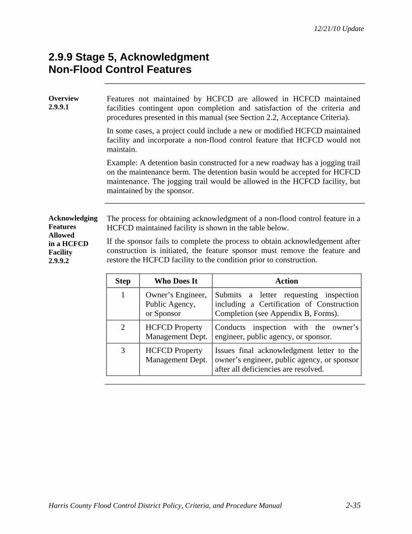
12/21/10 Update
Harris County Flood Control District Policy, Criteria, and Procedure Manual 2-35
2.9.9 Stage 5, Acknowledgment Non-Flood Control Features
Overview 2.9.9.1
Features not maintained by HCFCD are allowed in HCFCD maintained facilities contingent upon completion and satisfaction of the criteria and procedures presented in this manual (see Section 2.2, Acceptance Criteria).
In some cases, a project could include a new or modified HCFCD maintained facility and incorporate a non-flood control feature that HCFCD would not maintain.
Example: A detention basin constructed for a new roadway has a jogging trail on the maintenance berm. The detention basin would be accepted for HCFCD maintenance. The jogging trail would be allowed in the HCFCD facility, but maintained by the sponsor.
Acknowledging Features Allowed in a HCFCD Facility 2.9.9.2
The process for obtaining acknowledgment of a non-flood control feature in a HCFCD maintained facility is shown in the table below.
If the sponsor fails to complete the process to obtain acknowledgement after construction is initiated, the feature sponsor must remove the feature and restore the HCFCD facility to the condition prior to construction.
Step Who Does It Action
1 Owner’s Engineer, Public Agency, or Sponsor
Submits a letter requesting inspection including a Certification of Construction Completion (see Appendix B, Forms).
2 HCFCD Property Management Dept.
Conducts inspection with the owner’s engineer, public agency, or sponsor.
3 HCFCD Property Management Dept.
Issues final acknowledgment letter to the owner’s engineer, public agency, or sponsor after all deficiencies are resolved.

12/21/10 Update
Harris County Flood Control District Policy, Criteria, and Procedure Manual 2-36
2.10 Concurrent Activities
Concurrent Activities 2.10.1
Some projects will require some activities to take place while developing the drainage or design report, preparing construction drawings, and/or building the project.
Right-of-Way:
When a HCFCD right-of-way dedication or conveyance is needed, or the non-flood control feature needs right-of-way, begin the process early.
Platting:
When the development project is to be platted, begin the preparation and coordination with HCFCD.
Interlocal or Turf Establishment Agreements:
When an interlocal or turf establishment agreement is needed for the project or non-flood control feature, begin the preparation and coordination with HCFCD.
Acceptance for HCFCD Maintenance:
For projects that modify or create a new HCFCD facility, initiate all applicable activities as early as necessary to complete the “Application for Acceptance of Maintenance of a Drainage/Detention Facility”.
Non-Flood Control Features Allowed in a HCFCD facility:
For non-flood control features in a HCFCD maintained facility, initiate all applicable activities as early as necessary to obtain an acknowledgment of construction completion.

12/21/10 Update
Harris County Flood Control District Policy, Criteria, and Procedure Manual 2-37
2.11 Right-of-Way
HCFCD Right-of-Way Conveyance or Dedication 2.11.1
For projects requiring new or additional right-of-way, initiate dedication to the public or conveyance to HCFCD as early in the process as possible.
HCFCD will not accept the work until the right-of-way dedication or conveyance is completed. The dedication and conveyance process is presented in this manual in Section 15, Right-of-Way.
Right-of-Way for Non-Flood Control Features 2.11.2
If the proposed non-flood control feature requires new or additional right-of-way, the sponsor should begin to acquire the right-of-way as early in the process as possible.
HCFCD will not allow construction of the non-flood control feature in the HCFCD facility until the right-of-way dedication or conveyance for the feature is completed.
Property Ownership Determination 2.11.3
The sponsor is required to provide a property ownership map and deeds showing existing property ownerships and easements relative to the proposed feature location.
The HCFCD Property Management Department will make its right-of-way information available upon request.
Abstracting right-of-way is the sponsor’s responsibility.
HCFCD Fee Strip 2.11.4
If HCFCD has fee ownership at the location of the proposed non-flood control feature, sponsors must obtain an easement from HCFCD for the proposed feature.
The process for obtaining an easement from HCFCD for a non-flood control feature is presented in this manual in Section 15.4, Easements for Pipelines, Utilities, and Roadways.
HCFCD or Public Easement 2.11.5
If HCFCD or public has an easement at the location of the proposed non-flood control feature, the sponsor is responsible for obtaining an easement or written legal permission from the fee owner for the proposed feature.
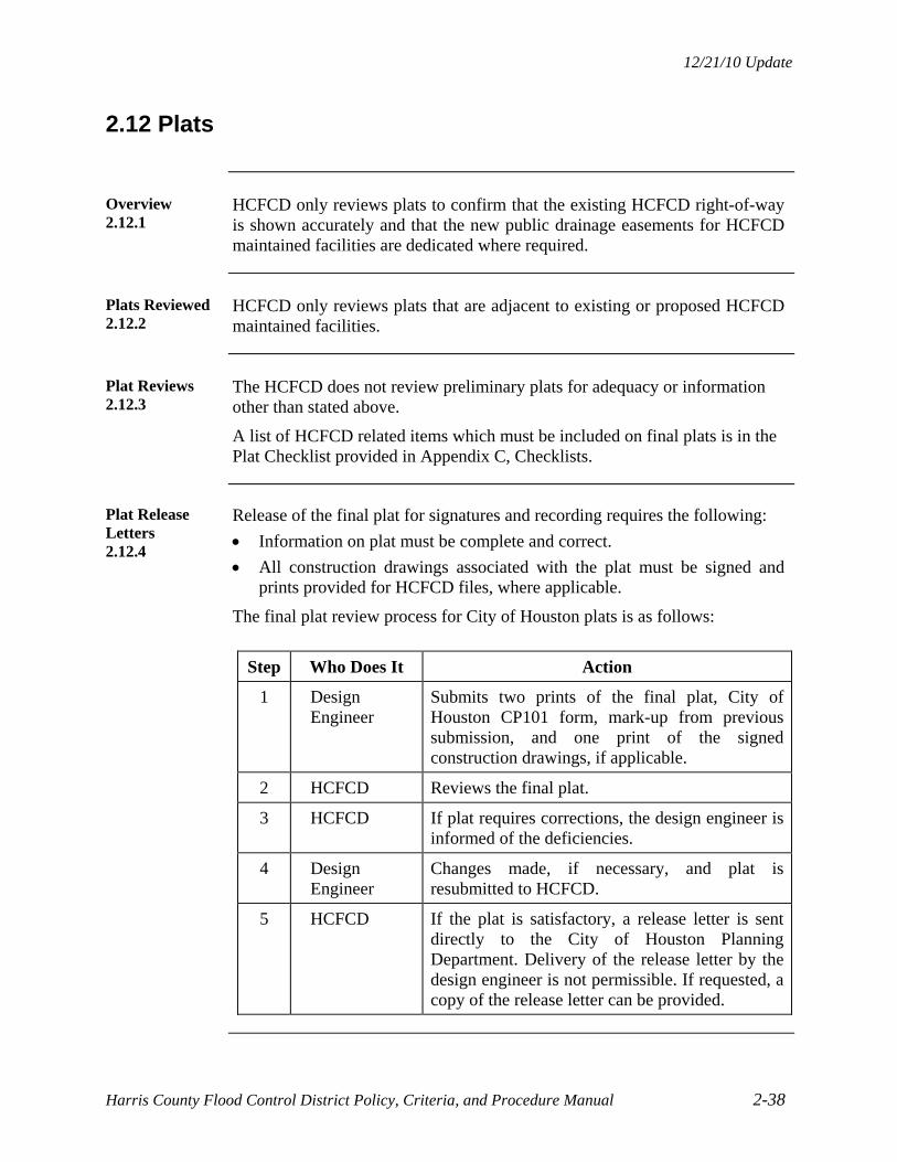
12/21/10 Update
Harris County Flood Control District Policy, Criteria, and Procedure Manual 2-38
2.12 Plats
Overview 2.12.1
HCFCD only reviews plats to confirm that the existing HCFCD right-of-way is shown accurately and that the new public drainage easements for HCFCD maintained facilities are dedicated where required.
Plats Reviewed 2.12.2
HCFCD only reviews plats that are adjacent to existing or proposed HCFCD maintained facilities.
Plat Reviews 2.12.3
The HCFCD does not review preliminary plats for adequacy or information other than stated above.
A list of HCFCD related items which must be included on final plats is in the Plat Checklist provided in Appendix C, Checklists.
Plat Release Letters 2.12.4
Release of the final plat for signatures and recording requires the following:
Information on plat must be complete and correct.
All construction drawings associated with the plat must be signed and prints provided for HCFCD files, where applicable.
The final plat review process for City of Houston plats is as follows:
Step Who Does It Action
1 Design Engineer
Submits two prints of the final plat, City of Houston CP101 form, mark-up from previous submission, and one print of the signed construction drawings, if applicable.
2 HCFCD Reviews the final plat.
3 HCFCD If plat requires corrections, the design engineer is informed of the deficiencies.
4 Design Engineer
Changes made, if necessary, and plat is resubmitted to HCFCD.
5 HCFCD If the plat is satisfactory, a release letter is sent directly to the City of Houston Planning Department. Delivery of the release letter by the design engineer is not permissible. If requested, a copy of the release letter can be provided.

12/21/10 Update
Harris County Flood Control District Policy, Criteria, and Procedure Manual 2-39
2.13 Interlocal Agreements
Overview 2.13.1
An interlocal agreement between HCFCD and another public agency or non-flood control feature sponsor is sometimes necessary to:
Allow an agency or feature sponsor to work or build in the HCFCD right-of-way.
Jointly fund a project.
Identify ownership and maintenance responsibilities.
Coordination 2.13.2
Coordinate preparation of interlocal agreements with the HCFCD Property Management Department or Capital Projects Department, as appropriate. The Harris County Attorney assigned to HCFCD must review and approve all agreements.
Since interlocal agreements can take time to complete, start them as early as possible, such as near the completion of the Drainage or Design Report, Stage 2.
The interlocal agreement must be fully-executed prior to beginning construction.
Guidelines 2.13.3
Typical guidelines are:
HCFCD can enter into interlocal agreements only with other governmental entities such as cities, TxDOT, and utility districts. HCFCD cannot enter into interlocal agreements with organizations such as homeowner associations. HCFCD can enter into landscape maintenance agreements with homeowner associations or individuals.
One public entity cannot give something of value to another public entity. There must be some form of equitable compensation such as money, services, or overall benefit to the taxpayers.
Reason for the interlocal agreement should be clearly stated in the recital (Whereas) statements.
Responsibilities for each party should be clearly stated.
For non-flood control features, include all applicable conditions listed in Section 2.2, Acceptance Criteria.
If the agreement creates an obligation on the part of HCFCD, the agreement must provide for funding.
HCFCD cannot indemnify another party.
Provisions for termination should be included.

12/21/10 Update
Harris County Flood Control District Policy, Criteria, and Procedure Manual 2-40
2.14 Federal Projects
Overview 2.14.1
Modifications to channels or detention basins constructed as part of an U.S. Army Corps of Engineers’ project must be approved by the Corps of Engineers, Galveston District. The Corps of Engineers makes sure the effectiveness and integrity of federal flood control projects are not diminished by physical or structural changes.
Corps of Engineers’ Projects 2.14.2
The Corps of Engineers' project locations currently requiring Corps of Engineers approval are as follows:
Channel Reach Brays Bayou Calhoun to Old Westheimer Road
White Oak Bayou Mouth to Cole Creek
Vince Bayou Mouth to Hernandez Street
Little Vince Bayou Mouth to Wichita Street
Buffalo Bayou Sam Houston Tollway to S.H. 6
Clear Creek Second Outlet Channel at S.H. 146
Sims Bayou Mouth to Mykawa Road
Detention Basin Location Addicks Reservoir West Harris County
Barker Reservoir West Harris County
Buyouts Location Cypress Creek Varied
Buyouts 2.14.3
Land use requirements exist for land purchased by HCFCD as part of a Corps of Engineers or Federal Emergency Management Agency (FEMA) buyout program.
FEMA buyout properties are located in various locations in Harris County. Coordinate proposed modifications to these properties with HCFCD as early as possible.
Continued on next page

12/21/10 Update
Harris County Flood Control District Policy, Criteria, and Procedure Manual 2-41
2.14 Federal Projects, Continued
Projects Reviewed 2.14.4
Typical projects the HCFCD and Corps of Engineers review are:
Channel enlargements or modifications
Detention basin modifications
Storm sewer outfall pipes, both new and modifications
Bridge and utility crossings, both new and modifications
Addition of non-flood control features such as trees and trails
Basically, any project that modifies or is within a channel or detention basin constructed as part of a Corps of Engineers project needs to be reviewed, as well as, any modification of land acquired as part of a Corps of Engineers or FEMA buyout project.
Continued on next page

12/21/10 Update
Harris County Flood Control District Policy, Criteria, and Procedure Manual 2-42
2.14 Federal Projects, Continued
Review Procedure for Corps of Engineers’ Projects 2.14.5
The following table shows the review procedure for construction drawings submitted to the HCFCD Project Review Section for projects constructed or funded by the Corps of Engineers.
Step Who Does It Action
1 Design Engineer Proceeds with Stage 1, Initiation and Stage 2, Drainage or Design Report with the appropriate HCFCD Department.
2 HCFCD Provides specific design criteria for the subject reach or location.
3 Design Engineer Submits one set of prints and completed checklist.
4 HCFCD Reviews construction drawings and returns mark-ups to design engineer.
5 Design Engineer Revises construction drawings, if necessary. Contacts HCFCD if there are any questions or issues. Submits print, checklists, and markups.
6 HCFCD Confirms final construction drawings are in compliance. Notifies design engineer.
7 Design Engineer Submits two 11” x 17” sealed paper copies of construction drawings to HCFCD.
8 HCFCD Forwards the two copies to the Corps of Engineers, Galveston District for their review, comments, and concurrence.
9 Corps of Engineers
Sends a reply to HCFCD with comments or concurrence (allow 2 to 4 weeks for reply).
10 HCFCD Notifies design engineer of Corps of Engineers concurrence.
11 Design Engineer Submits final construction drawings – original, two prints, checklists, and markups, to HCFCD.
12 HCFCD Signs drawings and returns originals to design engineer.

12/21/10 Update
Harris County Flood Control District Policy, Criteria, and Procedure Manual 2-43
2.15 Regional Flood Control Projects
Introduction 2.15.1
The HCFCD supports regional drainage as stated in Section 1.3.7, Policy VII: HCFCD Support of Regional Drainage. Regional projects are generally more efficient and reliable than individual projects.
Adopted Regional Projects 2.15.2
The regional project watersheds, Harris County Commissioners Court approval dates, and adopted impact fees are:
Watershed Approval Date Fee
White Oak Bayou November 6, 1984 $3,000/acre
Brays Bayou October 15, 1985 $7,000/acre
Sims Bayou October 15, 1985 $3,000/acre
Langham Creek March 25, 1986 $3,100/acre
Greens Bayou June 24, 1986 $3,300/acre
Cypress Creek November 18, 1986 $4,000/acre
Previous Commissioner Court Actions 2.15.3
This manual replaces the regional plan implementation clarifications adopted by Commissioners Court on April 3, 1990; November 13, 1990; February 5, 1991; and August 8, 2000.
New Development 2.15.4
New development is defined as any increase in impervious cover or change in land condition that affects the amount or rate of runoff from a property. The relationship between land use, percent impervious, and percent development is provided in Section 3.5.1, Relationship to Development.
New development acreage as used to calculate detention volume or impact fees is determined using the entire property, not just the area of impervious cover or drainage improvement, unless a substantial portion is left undisturbed.
Example: Single family subdivisions with lots less than ¼ acre and schools with open areas built on undeveloped property are considered new development.
Continued on next page
12/21/10 Update
Harris County Flood Control District Policy, Criteria, and Procedure Manual 2-44
2.15 Regional Flood Control Projects, Continued
Detention Volume and Impact Fee Calculation 2.15.5
The acreage used to calculate detention volume or impact fees is the new development acreage minus:
Existing or proposed HCFCD right-of-way.
Proposed right-of-way along existing major thoroughfares intended for road widening.
Major pipeline or energy corridors not useful for development.
Impact Fee Collection Criteria 2.15.6
Impact fees can only be collected in watersheds or sub-watersheds:
With a regional or master plan adopted by Harris County Commissioners Court,
Where system capacity exists for the new development as determined by the HCFCD and accepted by Harris County Commissioners Court, and
Where the new development can convey its 10% and 1% exceedance probability runoff to the regional project without increasing flood risks for others.
Impact Fee Payment 2.15.7
Rules regarding impact fee payments are as follows:
Pay impact fees in full by cashiers check made payable to the HCFCD prior to plan approval.
Apply previous partial payments, if any, to the amount due.
Permanent improvements to the regional project constructed or contributed by a developer in accordance with a formal agreement with the HCFCD can be recognized as payment toward the amount due.
No land shall pay the full fee more than once.
If another government agency requires site-specific detention and the detention facility constructed equals or exceeds HCFCD criteria in this manual, then no impact fee is required. If the detention volume does not equal or exceed HCFCD criteria, then the impact fee is reduced proportional to the ratio of detention volume provided.
Continued on next page

12/21/10 Update
Harris County Flood Control District Policy, Criteria, and Procedure Manual 2-45
2.15 Regional Flood Control Projects, Continued
Alternative to Site-Specific Detention 2.15.8
As an alternative to site-specific detention in a watershed with a regional program and system capacity is not available, the new development may, upon approval by HCFCD, construct components of the regional project to mitigate its impact. (See exception Section 2.15.10, Upper Langham Creek.) The following criteria apply:
The new development demonstrates to the satisfaction of the flood plain administrator and HCFCD that the proposed work mitigates the impact.
The new development can convey its runoff to the regional project without increasing flood risks for others.
Reasonable and necessary cost for such improvement (land, engineering, and construction) is submitted for verification.
Costs in excess of the established impact fee are borne by the new development.
If costs are less than the impact fee due, the difference is paid to the HCFCD.
Interim Site-Specific Detention 2.15.9
Site-specific detention facilities can be classified as interim if an agreement is approved by Commissioners Court and all costs associated with reclaiming the interim facility is borne by the development interest. The interim designation allows the detention facility to be taken out of service and the land reclaimed for development or other purpose when:
All criteria is satisfied in Section 2.15.6, Impact Fee Collection Criteria, and
The impact fee in place when the interim facility is removed is paid. Note: See exception Section 2.15.10, Upper Langham Creek
Continued on next page

12/21/10 Update
Harris County Flood Control District Policy, Criteria, and Procedure Manual 2-46
2.15 Regional Flood Control Projects, Continued
Upper Langham Creek 2.15.10
For the Langham Creek watershed upstream of Barker-Cypress Road, the “Upper Langham Creek Capital Improvement and Impact Fee Utilization Plan” was adopted by Harris County Commissioners Court on January 27, 2009. This plan has the impact fee of $3,100/acre that was adopted in March 1986. In addition to complying with the criteria in Regional Flood Control Projects, Section 2.15.1 to 2.15.7, new developments within the Upper Langham Creek service area are required to:
Pay the impact fee to cover the costs of right-of-way acquisition, pipeline adjustments, control structures, and environmental mitigation, and
Construct their share of the detention volume within the Upper Langham Creek Plan stream corridor and/or detention basins to mitigate the hydrologic effects of land development and flood plain reduction.
Continued on next page

12/21/10 Update
Harris County Flood Control District Policy, Criteria, and Procedure Manual 2-47
2.15 Regional Flood Control Projects, Continued
One Acre Limit 2.15.11
Due to practical considerations and questionable effectiveness, new developments less than or equal to one acre can pay the impact fee in accordance with Section 2.15.7, Impact Fee Payment instead of providing site specific detention.
Compliance Summary 2.15.12
Based on the policies and criteria in this manual, the table below is provided to assist in determining HCFCD requirements for a new development project.
Conditions
Provide Site Specific
Detention
Pay Impact
Fee Comments
Regional Watershed Program
System Capacity Available and
Can Convey Runoff to Regional Project Without Impact and
New Development – Any Size
X See Section 2.15.7, Impact Fee Payment
System Capacity Not Available
and New Development >1 acre
X
See Section 2.15.8, Alternatives to Site-Specific Detention
System Capacity Not Available
and New Development1 acre
X See Section 2.15.7, Impact Fee Payment
No Regional Watershed Program – See Section 6.1.1, When to Use, and Section 6.1.2, Where Not Required.
Impact Fee Not Required 2.15.13
The impact fee is not required for
Only one single family residence where no major changes in existing conditions are proposed and it is not part of a larger development project.
Redevelopment projects that do not increase the amount of impervious cover or the runoff from the site.


12/21/10 Update
Harris County Flood Control District Policy, Criteria, and Procedure Manual 3-1
SECTION 3 – HYDROLOGY
3.1 Introduction
Overview 3.1.1
Estimating peak discharges and routing flow hydrographs for existing and future conditions is necessary for the planning, analysis, and design of both new development and redevelopment and associated flood damage reduction facilities. This section presents hydrologic methodologies for use in Harris County.
When Analysis Is Required 3.1.2
A hydrologic analysis is required when:
A new HCFCD maintained facility is proposed.
An existing HCFCD maintained facility is modified.
A private development or public agency project outfalls into a HCFCD maintained facility that was not designed and constructed for the proposed development’s flows.
A non-flood control feature is placed in or across a HCFCD maintained facility that would impact flows.
Harris County requests HCFCD review of new developments in unincorporated Harris County.
Computer Models and Programs 3.1.3
Current effective models use the HEC-HMS and HEC-RAS computer programs. Guidance for applying these programs is in the HCFCD Hydrology and Hydraulics Guidance Manual. Use the HCFCD Hydrologic and Hydraulic Modeling and Management Standards when modifying HEC-HMS and HEC-RAS models and associated data sets. Obtain current versions of the standards from the HCFCD website.
If a channel has not been modeled, an approximate or simplified application of the methodologies presented in this section may be sufficient. Coordination with HCFCD as early as possible is recommended.
In some cases, HEC-HMS and HEC-RAS cannot accurately model some projects or hydrologic conditions. Inform HCFCD in writing early in the review process of the computer program that will be used, justification for using the program(s), and provide program documentation, if required, to facilitate the review.
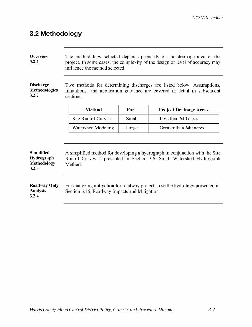
12/21/10 Update
Harris County Flood Control District Policy, Criteria, and Procedure Manual 3-2
3.2 Methodology
Overview 3.2.1
The methodology selected depends primarily on the drainage area of the project. In some cases, the complexity of the design or level of accuracy may influence the method selected.
Discharge Methodologies 3.2.2
Two methods for determining discharges are listed below. Assumptions, limitations, and application guidance are covered in detail in subsequent sections.
Method For … Project Drainage Areas
Site Runoff Curves Small Less than 640 acres
Watershed Modeling Large Greater than 640 acres
Simplified Hydrograph Methodology 3.2.3
A simplified method for developing a hydrograph in conjunction with the Site Runoff Curves is presented in Section 3.6, Small Watershed Hydrograph Method.
Roadway Only Analysis 3.2.4
For analyzing mitigation for roadway projects, use the hydrology presented in Section 6.16, Roadway Impacts and Mitigation.

12/21/10 Update
Harris County Flood Control District Policy, Criteria, and Procedure Manual 3-3
3.3 Site Runoff Curves
Introduction 3.3.1
Site Runoff Curves are a simplified method to determine peak discharges for relatively small areas which involve the design and analysis of stormwater detention facilities or overland sheet flow conditions for new developments.
Site Runoff Curves are based on the Watershed Modeling Method for Harris County so peak discharges could be determined for smaller areas using a consistent and simplified methodology.
Applications 3.3.2
Site Runoff Curves are used to determine peak flows for:
Onsite detention facilities.
Overland flow situations (extreme event).
Storm sewer systems or overland swales to handle the overland flow.
Closed conduits.
Limitations 3.3.3
Use Site Runoff Curves when:
Only peak flows are needed. The drainage area is less than 640 acres.
Do not use flows from the Site Runoff Curves to define or modify effective FEMA regulatory flood plains or floodway.
Site Runoff Curves 3.3.4
The 10% and 1% exceedance probability peak discharges are on the Site Runoff Curves in Exhibits 3-1 and 3-2, respectively. Two variables needed are:
Size of the drainage area in acres.
Amount of impervious cover defined as a percentage of the drainage area.
Continued on next page

12/21/10 Update
Harris County Flood Control District Policy, Criteria, and Procedure Manual 3-4
3.3 Site Runoff Curves, Continued
Equations for Site Runoff Curves 3.3.5
The equation for the Site Runoff Curves is:
Q = bAm
where: Q = peak discharge (cfs)
A = drainage area (acres)
m = 1.0 for 1 to 20 acres and 0.823 for more than 20 acres up to 640 acres
b = variable dependent on impervious cover. See table below.
Notes:
Interpolate “b” linearly to determine peak discharges for percentages of impervious cover between those listed in the table.
For areas with more than 85% impervious cover, use the 85% impervious curve.
Plots of these curves are shown in Exhibits 3-1 and 3-2.
Impervious 10 % Prob. 1% Prob.
Cover ≤ 20 acres > 20 acres ≤ 20 acres > 20 acres
0% 1.2 2.1 2.0 3.4
10% 1.5 2.6 2.5 4.3
20% 1.8 3.1 3.1 5.3
30% 2.3 3.9 3.8 6.4
40% 2.7 4.6 4.3 7.3
85% 3.5 5.9 5.1 8.7

12/21/10 Update
Harris County Flood Control District Policy, Criteria, and Procedure Manual 3-5
3.4 Watershed Modeling Method
Introduction 3.4.1
The Watershed Modeling Method involves use of the hydrologic methodology developed to identify regulatory flood plains in Harris County, estimate affects of proposed developments or projects, and identify flood damage reduction and mitigation projects.
Current guidance for watershed modeling in Harris County is in the HCFCD Hydrology and Hydraulics Guidance Manual.
Applications 3.4.2
The Watershed Modeling Method is used when hydrograph analysis is needed to:
Analyze and design channels and detention basins for new land development or public agency projects:
– For drainage areas greater than 640 acres.
– Where correlation with existing HEC-HMS or HEC-RAS is necessary.
– Where development of runoff hydrographs with consistent timing is necessary.
Define or modify effective FEMA regulatory flood plains or floodway due to the new development or changes to HCFCD maintained facilities.
Note: Analysis is run along the entire length of the main stem.
Limitations 3.4.3
Use the Watershed Modeling Method only for areas with an open channel or major enclosed channel.
Results may not be valid for drainage areas less than 640 acres.
The Watershed Modeling Method may be used where complexity of a project justifies a detailed analysis for a project drainage area greater than 300 acres and less than 640 acres.
Optional Technique 3.4.4
For small to moderate project drainage areas (less than 640 acres), the Optional Project Routing Technique in Section 3.7 can be used for calculating detention volumes and sizing outflow structures. This technique is not the same as the Watershed Modeling Method because:
Consistent hydrograph timing with current models is not considered The methodology developed for Harris County to calculate TC and R is
not used, and It is for small to moderate project drainage areas only.

12/21/10 Update
Harris County Flood Control District Policy, Criteria, and Procedure Manual 3-6
3.5 Impervious Cover
Relationship to Development 3.5.1
The generalized relationship between percent land development and percent impervious cover is shown below for various land uses:
Land Use Categories
Land Use Descriptions
% Impervious % Development
Undeveloped Unimproved, natural, or agricultural
0 0
Residential – Rural Lot
≥ 5 acre ranch or farm 5 0
Residential – Large Lot (Newer)
> ½ acre new residential neighborhoods , storm sewers or roadside ditches with adequate capacity
20 100
Residential – Large Lot (Older)
> ¼ acre, older neighborhoods with limited capacity roadside ditches
20 50
Residential – Small Lot
≤ ¼ acre 40 100
Schools Schools with non-paved areas
40 50
Developed Green Areas
Parks or golf courses 15 50
Light Industrial/ Commercial
Office parks, nurseries, airports, warehouses, or manufacturing with non-paved areas
60 100
High Density Commercial, business, industrial, or apartments
85 100
Isolated Transportation
Highway or major thoroughfare corridors
90 100
Water Detention basins, lakes, and channels
100 100
Note: Based on HCFCD Hydrology and Hydraulics Guidance Manual
Continued on next page

12/21/10 Update
Harris County Flood Control District Policy, Criteria, and Procedure Manual 3-7
3.5 Impervious Cover, Continued
Detention Basins, Lakes, Channels, Roadside Ditches 3.5.2
Consider detention basins, lakes, channels, and roadside ditches to be 100% impervious when conducting hydrologic analysis for estimating runoff or sizing HCFCD facilities. Use the area within the top of bank.
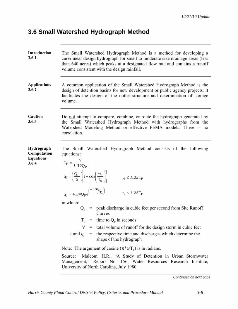
12/21/10 Update
Harris County Flood Control District Policy, Criteria, and Procedure Manual 3-8
3.6 Small Watershed Hydrograph Method
Introduction 3.6.1
The Small Watershed Hydrograph Method is a method for developing a curvilinear design hydrograph for small to moderate size drainage areas (less than 640 acres) which peaks at a designated flow rate and contains a runoff volume consistent with the design rainfall.
Applications 3.6.2
A common application of the Small Watershed Hydrograph Method is the design of detention basins for new development or public agency projects. It facilitates the design of the outlet structure and determination of storage volume.
Caution 3.6.3
Do not attempt to compare, combine, or route the hydrograph generated by the Small Watershed Hydrograph Method with hydrographs from the Watershed Modeling Method or effective FEMA models. There is no correlation.
Hydrograph Computation Equations 3.6.4
The Small Watershed Hydrograph Method consists of the following equations:
PP Q.
VT
391
p
iPi T
tcos
Qq 1
2
Pi T.t 251
P
iT
t.
Pi eQ.q31
344 Pi T.t 251
in which: QP = peak discharge in cubic feet per second from Site Runoff
Curves
TP = time to QP in seconds
V = total volume of runoff for the design storm in cubic feet
ti and qi = the respective time and discharges which determine the shape of the hydrograph
Note: The argument of cosine (B*ti/Tp) is in radians.
Source: Malcom, H.R., “A Study of Detention in Urban Stormwater Management,” Report No. 156, Water Resources Research Institute, University of North Carolina, July 1980.
Continued on next page

12/21/10 Update
Harris County Flood Control District Policy, Criteria, and Procedure Manual 3-9
3.6 Small Watershed Hydrograph Method, Continued
Total Volume of Runoff, V 3.6.5
Multiply the drainage area by the depth of direct runoff to calculate the total volume of runoff, V.
Direct Runoff, 1% Probability Event 3.6.6
The depths of direct runoff for the 24-hour, 1% probability rainfall events are provided below for each rainfall region and for three impervious conditions. Use linear interpolation for other impervious conditions.
The values are based on loss rates from the HCFCD Hydrology and Hydraulics Guidance Manual.
Watershed: Name and HCFCD Letter Designation
Total Rainfall (inches)
Direct Runoff (inches) 0%
Impervious 40%
Impervious 85%
Impervious
Region 1
Addicks Tributaries (U) Barker Tributaries (T) Cypress Creek (K)
12.4 7.9 9.7 11.7 Little Cypress Creek (L) Spring Creek (J) Willow Creek (M)
Region 2
Brays Bayou (D) Buffalo Bayou (W)
13.2 11.1 12.0 12.9 Greens Bayou (P) Hunting Bayou (H) Luce Bayou (S) San Jacinto River (G) White Oak Bayou (E)
Region 3
Armand Bayou (B) Carpenters Bayou (N) Cedar Bayou (Q) Clear Creek (A)
13.5 10.6 11.7 13.1 Galveston Bay (F) Goose Creek (O) Jackson Bayou (R) Sims Bayou (C) Vince Bayou (I)
Continued on next page
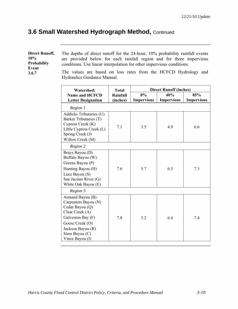
12/21/10 Update
Harris County Flood Control District Policy, Criteria, and Procedure Manual 3-10
3.6 Small Watershed Hydrograph Method, Continued
Direct Runoff, 10% Probability Event 3.6.7
The depths of direct runoff for the 24-hour, 10% probability rainfall events are provided below for each rainfall region and for three impervious conditions. Use linear interpolation for other impervious conditions.
The values are based on loss rates from the HCFCD Hydrology and Hydraulics Guidance Manual.
Watershed: Name and HCFCD Letter Designation
Total Rainfall (inches)
Direct Runoff (inches) 0%
Impervious 40%
Impervious 85%
Impervious
Region 1
Addicks Tributaries (U) Barker Tributaries (T) Cypress Creek (K)
7.1 3.5 4.9 6.6 Little Cypress Creek (L) Spring Creek (J) Willow Creek (M)
Region 2
Brays Bayou (D) Buffalo Bayou (W)
7.6 5.7 6.5 7.3 Greens Bayou (P) Hunting Bayou (H) Luce Bayou (S) San Jacinto River (G) White Oak Bayou (E)
Region 3
Armand Bayou (B) Carpenters Bayou (N) Cedar Bayou (Q) Clear Creek (A)
7.8 5.2 6.4 7.4 Galveston Bay (F) Goose Creek (O) Jackson Bayou (R) Sims Bayou (C) Vince Bayou (I)

12/21/10 Update
Harris County Flood Control District Policy, Criteria, and Procedure Manual 3-11
3.7 Optional Project Routing Technique
Introduction 3.7.1
The Optional Project Routing Technique can be used for calculating detention volume and sizing the outflow structure for small to moderate project drainage areas.
The design engineer has the option to use this technique. If a model other than HEC-HMS is used or another model is used in conjunction with HEC-HMS, contact the HCFCD for verification of the model and technical approach to be used.
Applications 3.7.2
The Optional Project Routing Technique is used for analysis and design of detention basins for new land development or public agency projects:
For drainage areas less than 640 acres.
To facilitate analysis and design using common computer programs and techniques.
Limitations 3.7.3
Do not use this technique
– To correlate with existing HCFCD HEC-HMS or HEC-RAS watershed models.
– Define or modify effective FEMA regulatory flood plains or floodways.
When comparing pre- and post- project peak flows, compare at the detention basin outfall in the outfall channel and at least three nodes downstream on the main stem.
Clark’s Unit Hydrograph 3.7.4
If Clark’s Unit Hydrograph approach is used in the HEC-HMS model:
Estimate TC using a velocity based method.
Adjust R such that the peak discharge matches the Site Runoff Curve peak value and the runoff volume approximates the value in the effective model or the value calculated using direct runoff depths in Section 3.6.6, Direct Runoff, 1% Probability Event and Section 3.6.7, Direct Runoff, 10% Probability Event.

12/21/10 Update
Harris County Flood Control District Policy, Criteria, and Procedure Manual 3-12
3.8 Watershed Diversions
Introduction 3.8.1
In some cases, development and infrastructure projects divert stormwater from one watershed to another because it is not practical or feasible to convey stormwater to two different watersheds. A watershed diversion occurs when open channels and detention basins divert storm water from one main channel watershed to another, such as from the Willow Creek (M100-00-00) watershed to the Spring Creek (J100-00-00) watershed. The HCFCD unit letters designate different main channel watersheds.
Development and infrastructure projects that redirect stormwater from one tributary to another tributary within the same main channel watershed are not considered watershed diversions. Redirecting flow from the U101-03-00 watershed to the U101-06-00 watershed, or from the Halls Bayou (P118-00-00) watershed to the P138-00-00 watershed are not considered watershed diversions.
Note: With the flat terrain in most parts of Harris County, drainage boundaries between watersheds are not always clear and are dependent on rainfall severity and drainage improvements. Where drainage area boundaries are not easily identified, coordinate with the HCFCD.
Criteria 3.8.2
The following criteria applies in addition to the applicable criteria and considerations in the rest of this manual:
Document the existing and proposed watershed boundaries relative to the proposed project drainage area boundary.
Retain 100% of the runoff volume from the diverted area in addition to the detention volume calculated for the non-diverted area.
In addition to the events designated in Section 6.3.4, Outflow Rates, also restrict the outflow to the 50% exceedance probability, 24 hour event into the receiving channel.
For diverted areas larger than 50 acres, contact HCFCD prior to performing analysis to identify other criteria or conditions that may apply, and to coordinate analytical approach.
Considerations 3.8.3
Consider contacting the Texas Commission on Environmental Quality to find out if there is a surface water rights issue that needs to be addressed as a result of the proposed diversion.
To determine if FEMA related reviews and submittals are necessary, contact the local flood plain administrator.


12/21/10 Update
Harris County Flood Control District Policy, Criteria, and Procedure Manual 4-1
SECTION 4 – HYDRAULICS
4.1 Introduction
Overview 4.1.1
The water surface profile or hydraulic gradeline is essential to the design and analysis of existing or proposed channels, detention basins, and closed conduits. The analysis involves calculating energy losses due to friction, obstructions, transitions, bends, and confluences. When calculating water surface profiles either by hand or with a computer program, include all relevant sources of headloss.
Design of channels and closed conduits generally focus on minimizing energy losses (results in a smaller channel/conduit) and controlling dissipation of excessive energy (reduces erosion problems).
When Analysis Is Required 4.1.2
A hydraulic analysis is required when:
A new HCFCD maintained facility is proposed.
An existing HCFCD maintained facility is modified.
A private development or public agency project outfalls into a HCFCD maintained facility.
A non-flood control feature is placed in or across a HCFCD maintained facility.

12/21/10 Update
Harris County Flood Control District Policy, Criteria, and Procedure Manual 4-2
4.2 Methods
Overview 4.2.1
The method selected depends on the type of project, complexity of the hydraulic design, and the level of accuracy desired.
Normal Depth 4.2.2
For closed conduits or channels with the flow confined in a uniform cross section, few obstructions or transitions, and little or no backwater from downstream, the water surface will approximate normal depth. Manning’s Equation is commonly used for calculating normal depth (see Section 4.3, Manning’s Equation).
Standard Step Method and Computer Programs 4.2.3
For channels with non-uniform sections, flow in the overbanks, and/or bridge or culvert crossings, the water surface can be calculated using the standard step method. The steady state HEC-RAS option incorporates the standard step method.
The reasons for using HEC-RAS are that:
It is widely used and accepted.
It offers flexibility in the design of channels.
Bridge, culvert, and expansion and contraction losses are calculated.
It is used in the FEMA Flood Insurance Studies in Harris County.
Its use will simplify and expedite reviews by HCFCD.
Guidance for applying HEC-RAS is in the HCFCD Hydrology and Hydraulics Guidance Manual. Use the HCFCD Hydrologic and Hydraulic Modeling and Management Standards when modifying HEC-RAS models and associated data sets. Obtain current versions of the standards from the HCFCD website.
Detention Basin Inflow/Outflow Design 4.2.4
For design of detention basin inflow and outflow structures, spreadsheet calculations using appropriate headloss equations are often used. The equations and discussion are in Section 6.6, Inflow Structures and Section 6.7, Outflow Structures.
Several commercial computer programs are available for designing detention basins and their associated inflow/outflow structures. Early coordination with HCFCD is recommended.
Alternative Methods 4.2.5
If an alternative method not presented in this manual is used for a specific problem, coordinate with HCFCD prior to initiation of the analysis.

12/21/10 Update
Harris County Flood Control District Policy, Criteria, and Procedure Manual 4-3
4.3 Manning’s Equation
Background 4.3.1
Manning's Equation is an empirical formula used to evaluate the effects of friction and resistance in open channels and closed conduits. For uniform flow conditions where the conduit or channel bottom and energy line are essentially parallel, Manning's Equation can be used to compute the normal depth.
Manning’s Equation 4.3.2
The equation is:
Q = (1.486/n) A R2/3 Sl/2
Where Q = Total discharge in cubic feet per second
n = Manning’s coefficient of roughness
A = Cross sectional area of channel or conduit in square feet
R = Hydraulic radius of the channel or conduit in feet
and S = Slope of energy line in feet per foot (same as channel bottom slope for uniform flow)
Subdividing Sections 4.3.3
Subdivide channel and overbank sections to represent differences in roughness across the section, particularly for natural, composite, or non-prismatic sections.
Gradually Varied Flow 4.3.4
For gradually varied flow conditions, the slope of the energy line at a given channel section can be computed using Manning's Equation. HEC-RAS uses Manning’s Equation to compute energy losses between cross sections due to friction.
Continued on next page
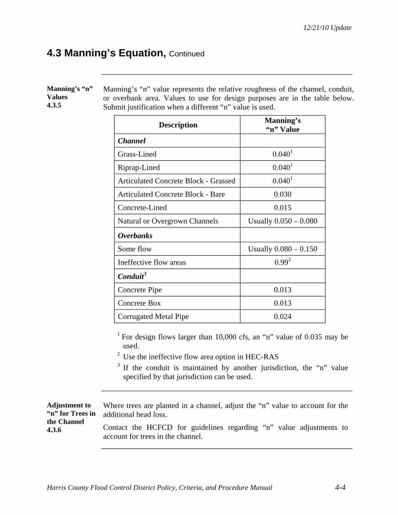
12/21/10 Update
Harris County Flood Control District Policy, Criteria, and Procedure Manual 4-4
4.3 Manning’s Equation, Continued
Manning’s “n” Values 4.3.5
Manning’s “n” value represents the relative roughness of the channel, conduit, or overbank area. Values to use for design purposes are in the table below. Submit justification when a different “n” value is used.
Description Manning’s “n” Value
Channel
Grass-Lined 0.0401
Riprap-Lined 0.0401
Articulated Concrete Block - Grassed 0.0401
Articulated Concrete Block - Bare 0.030
Concrete-Lined 0.015
Natural or Overgrown Channels Usually 0.050 – 0.080
Overbanks
Some flow Usually 0.080 – 0.150
Ineffective flow areas 0.992
Conduit3
Concrete Pipe 0.013
Concrete Box 0.013
Corrugated Metal Pipe 0.024
1 For design flows larger than 10,000 cfs, an “n” value of 0.035 may be
used. 2 Use the ineffective flow area option in HEC-RAS 3 If the conduit is maintained by another jurisdiction, the “n” value
specified by that jurisdiction can be used.
Adjustment to “n” for Trees in the Channel 4.3.6
Where trees are planted in a channel, adjust the “n” value to account for the additional head loss.
Contact the HCFCD for guidelines regarding “n” value adjustments to account for trees in the channel.

12/21/10 Update
Harris County Flood Control District Policy, Criteria, and Procedure Manual 4-5
4.4 Velocities
Maximum Velocities 4.4.1
Where average velocities exceed the maximum, provide erosion protection capable of withstanding the erosional forces (see Section 10, Erosion and Sediment Control).
Maximum average cross section velocities are based on a 1% exceedance probability flow. Values are presented in the table below.
Channel Description Maximum
Velocity (fps)1
Channel
Grass-Lined: Mostly Sand 4.0
Grass-Lined: Mostly Clay 6.0
Riprap-Lined – Gradation 12 8.0
Riprap-Lined – Gradation 22 10.0
Articulated Concrete Block Lined 10.0
Concrete-Lined 12.0
Overbanks and Existing Natural or Overgrown Channels Site Specific
Conduit
Concrete Pipe or Box 8.0
Corrugated Metal Pipe 6.0
1 For low turbulence areas only. 2 Gradations are defined in HCFCD Standard Specification Section 02378,
Riprap and Granular Fill.
Continuity Equation 4.4.2
The average velocity at a channel cross section or in a conduit is computed using the continuity equation:
Q = VA
where Q = discharge in cubic feet per second
V = average velocity in feet per second
and A = cross sectional flow area in square feet
12/21/10 Update
Harris County Flood Control District Policy, Criteria, and Procedure Manual 4-6
4.5 Cross Sections
Overview 4.5.1
Using accurate and current cross sections is essential to hydraulic analysis and developing water surface profiles.
Channels 4.5.2
Criteria for channel cross sections are:
Field survey channel sections at spacing sufficient to represent significant changes in channel dimensions. (Construction drawings should only be used for preliminary evaluations.)
Extend the sections into both overbanks.
Obtain overbank elevations either from field survey or the best topographic information available.
Conduits 4.5.3
Criteria for conduit cross sections are:
Use construction drawings.
Field verify pipe sizes and flowlines.
Detention Basins 4.5.4
Depending on the type of hydraulic analysis and the location of the detention basin relative to the outfall channel, either cross sections or a site topographic grid can be used.
Criteria for detention basins are:
Field survey the existing or proposed detention basin site.
Extend the survey into adjacent areas where stormwater is expected to flow or be stored.
Adjacent area elevations may be obtained from available topographic information if the accuracy is satisfactory.

12/21/10 Update
Harris County Flood Control District Policy, Criteria, and Procedure Manual 4-7
4.6 Starting Water Surface Elevation
Design of Channels 4.6.1
Base the starting water surface at the channel mouth on the normal depth in the design channel except as noted below.
When a channel outfalls into a tidal zone, use the average high tide as a starting water surface.
Design of Conduits 4.6.2
Use the top of the pipe or box as the starting water surface for a conduit.
Actual Flood Levels 4.6.3
In determining actual flood profiles or flood plain delineation in non-coastal areas, project the water-surface elevation from the outfall channel horizontally upstream until it intersects the flood profile on the design channel or conduit.
For coastal areas, use the results of the combined probability analysis to determine flood profiles.

12/21/10 Update
Harris County Flood Control District Policy, Criteria, and Procedure Manual 5-1
SECTION 5 – CHANNELS
5.1 Introduction
Uses 5.1.1
Natural and man-made channels are the primary area-wide conveyance system for carrying stormwater.
Channels are usually constructed or modified to:
Collect and convey stormwater.
Reduce the flooding potential on a property.
Mitigate increased flood stages caused by higher flows.
Accommodate the depth needed for a storm sewer outfall.
Terminology 5.1.2
Terminology and definitions associated with channels are in Appendix E, Terminology.
Review and Coordination 5.1.3
The review and coordination process for new channels or modification of existing HCFCD maintained channels is presented in Section 2.8, New or Modified HCFCD Facilities.
Analysis and Methodologies 5.1.4
General hydrologic and hydraulic analysis and methodologies are presented in Section 3, Hydrology and Section 4, Hydraulics. Hydraulic aspects specific to channels are presented in this section.
In This Section 5.1.5
This section covers HCFCD criteria for the design of channels. Specifically, this section covers:
Location and alignment.
General design criteria.
Typical sections.
Right-of-way.
Confluences.
Horizontal transitions.
Bends.
Other design topics for channels are covered in subsequent sections.

12/21/10 Update
Harris County Flood Control District Policy, Criteria, and Procedure Manual 5-2
5.2 Location and Alignment
Overview 5.2.1
Location and alignment of new or modified channels is important because it affects the:
Actual function of the channel.
Construction and maintenance costs.
Impact on natural and man-made features.
Considerations 5.2.2
Factors to consider when locating and establishing an alignment for a channel are to:
Follow existing/natural channels, ditches, swales, or other low areas.
Avoid crossing drainage divides.
Align the proposed channel pointing downstream at its confluence with the outfall channel.
Avoid tight channel bends.
Avoid areas of high erosion potential.
Provide adequate access for maintenance.
Minimize conflicts with existing buildings, homes, pipelines, and contaminated sites.
Minimize number of property owners affected, if possible.

12/21/10 Update
Harris County Flood Control District Policy, Criteria, and Procedure Manual 5-3
5.3 General Design Criteria
Design Frequencies 5.3.1
Design new channels to contain the 1% exceedance probability, 24-hour storm event for proposed watershed conditions.
When channel modifications are necessary to accommodate a proposed storm sewer outfall or to offset increased flows from a proposed development, design the modifications such that the 1% exceedance probability water surface profiles upstream or downstream are not increased above existing conditions.
Flowline Slope 5.3.2
Flowline slope criteria are as follows:
Minimum 0.05%.
Maximum controlled by maximum velocity (see Section 4.4, Velocities).
Note: Use a flowline slope greater than the minimum where possible to minimize standing water in the channel bottom and maximize capacity for a range of flows.
Existing Sections 5.3.3
Criteria for obtaining existing cross sections used in design of a new or modified channel are:
Field survey channel sections at a sufficient spacing for design.
Extend the survey beyond the existing or proposed channel right-of-way a minimum distance of 20 feet; where possible (see Section 11.1, Backslope Drainage Systems).
Natural Channels 5.3.4
When discharging stormwater from a manmade channel, detention basin, storm sewer, or pump into a natural channel, address potential erosion and siltation problems at the discharge point and downstream.
Channel Linings 5.3.5
The selection of channel lining is based on several factors including erosion potential, slope stability, conveyance, available right-of-way, cost, environmental situation, and aesthetics. Lining choices and design criteria are discussed in Section 10, Erosion and Sediment Control.
Continued on next page

12/21/10 Update
Harris County Flood Control District Policy, Criteria, and Procedure Manual 5-4
5.3 General Design Criteria, Continued
Hydraulic Structures 5.3.6
Hydraulic structures typically constructed within a channel are:
Backslope drainage systems.
Inflow and outflow structures.
Storm sewer outfalls.
Transition control structures.
Culverts.
Bridges (roads, pipelines, etc.).
Criteria for these types of hydraulic structures are presented in other sections of this manual.
Geotechnical Investigations 5.3.7
A geotechnical investigation is required for new HCFCD maintained channels and proposed work that deepens or widens an existing HCFCD channel. Previous investigations can be utilized, if applicable to the proposed project and the following design topics are addressed.
As a minimum, address the following:
Stability of the channel side slopes for short term, long term, and rapid drawdown conditions. (If channel depth ≤ 5 feet, slope stability analysis is not required.)
Location of ground water level(s).
Identification of dispersive soils.
Potential erosion problems.
Constructability issues.
Follow the geotechnical investigation requirements as provided in Appendix D, HCFCD Geotechnical Investigation Guidelines.
Environmental Investigations 5.3.8
Compliance with appropriate federal, state, and local environmental rules, laws, regulations, and permits is required when modifying or constructing HCFCD facilities (see Section 17, Environmental and Cultural Resources Compliance).
Maintenance Access Plan 5.3.9
For new channels, submit a maintenance access plan with the drainage or design report or the construction drawings.
For channel modifications, update the maintenance access plan reflecting any changes needed due to the proposed modification.

12/21/10 Update
Harris County Flood Control District Policy, Criteria, and Procedure Manual 5-5
5.4 Typical Cross Sections
Overview 5.4.1
Typical channel sections have minimum dimensions and required features based on construction and maintenance experience. Actual dimensions and shapes are determined from detailed hydraulic analysis, geotechnical investigations, and environmental, aesthetic, and multi-use considerations.
Typical channel sections are presented in this section.
Alternative sections are permissible; see Section 18 – Environmental, Recreation, and Aesthetic Features.
Trapezoidal Section 5.4.2
The most common channel shape is trapezoidal and the most common lining is grass. Concrete lining is used where right-of-way is limited or expensive, conveyance efficiency is critical, or erosion potential is high. Concrete lining does not provide structural support for the underlying soil.
The table below contains the criteria for both grass-lined and concrete-lined trapezoidal channel sections. See Exhibits 5-1 and 5-2 for typical sections.
Feature/Item Grass-Lined Concrete-Lined
Minimum bottom width 6 feet 6 feet
Bottom configuration See Section 5.4.3See Standard Concrete Lining Detail Sheet
Side slopes no steeper than 4:1 2:1
Backslope drainage system Yes No
Maintenance access and minimum berm widths
See Section 5.5.3, Minimum Berm Widths
Additional criteria for concrete-lined channels:
Minimum concrete lining thickness is 5 inches.
Concrete toe walls are required on all sides to reduce the chance of flow under the lining and decrease the chance of lining failure.
Access stairways are required for side slopes 2.5:1 and steeper. Locate stairways on the upstream side of road crossings and at intervals less than 1,500 feet.
Weep holes are required to accommodate subsurface drainage.
See HCFCD Standard Concrete Lining Detail Sheet in Appendix D, Standards and Details.
Continued on next page

12/21/10 Update
Harris County Flood Control District Policy, Criteria, and Procedure Manual 5-6
5.4 Typical Cross Sections, Continued
Bottom Configuration -Trapezoidal Grass-Lined 5.4.3
Use the table below to design the bottom of trapezoidal grass-lined channels.
Center depression = distance to depress channel centerline below toe of slope.
The purpose is to more accurately replicate the stable channel bottom shape that will naturally form, reduce erosion at the toe of slope, and reduce slope stability problems (see Exhibit 5-1).
Bottom Width Center
Depression Pipe Outlet Invert*
6 feet ≤ BW ≤ 20 feet 0.5 foot 1 foot above flowline
20 feet < BW ≤ 60 feet 1.0 foot At toe of slope
BW > 60 feet 3% cross slope At toe of slope
* At elevations indicated or 1 foot above normal water level, whichever is
higher.
Grass-Lined Bench Section 5.4.4
The bench section more closely replicates a natural channel than a trapezoidal section.
Benches can:
Improve the overall slope stability of the channel.
Reduce maintenance and repair costs.
Improve the aesthetics and habitat of the channel corridor.
Provide a location for trees, trails, and maintenance access.
The design considerations and criteria presented for grass-lined and concrete- lined channels apply to bench sections.
Criteria for benches:
Place at least 5 feet above the normal water level.
Minimum width – 10 feet.
Minimum cross slope toward channel – 2%.
Two typical bench sections are shown in Exhibit 5-3.
Continued on next page

12/21/10 Update
Harris County Flood Control District Policy, Criteria, and Procedure Manual 5-7
5.4 Typical Cross Sections, Continued
Rectangular Concrete-Lined Section 5.4.5
Rectangular concrete-lined channel sections are used when right-of-way is limited or expensive or additional depth is needed. The side slopes above the rectangular section can be either grass-lined or concrete-lined, depending on the conditions. The criteria for trapezoidal sections apply on the side slopes.
Criteria are:
Minimum bottom width is 8 feet.
Minimum height of vertical walls is 4 feet.
Equipment access ramps to the channel bottom are required for maintenance and rehabilitation work.
Access stairways are required. Recommended locations are on the upstream side of road crossings and at intervals less than 1500 feet.
See Standard Concrete Lining Detail Sheet in Appendix D, Standards and Details.
A typical section is shown in Exhibit 5-4.
Maintenance Access Alternatives 5.4.6
For a grass-lined bench section, maintenance access can be on the bench as shown on Exhibit 5-5. Criteria for the bench is:
Place at least 5 feet above the normal water level and no more than 5 feet below the top of bank.
Minimum width – 20 feet.
Minimum cross slope toward channel – 2%.
Side slope above the bench is no steeper than 5:1.
Transition back to natural ground at all maintenance access points at a gradient no steeper than 7% (14:1).
For grass-lined channels with side slopes no steeper than 8:1, maintenance access can be along the slope itself (see Exhibit 5-5).

12/21/10 Update
Harris County Flood Control District Policy, Criteria, and Procedure Manual 5-8
5.5 Right-of-Way
Overview 5.5.1
This section provides criteria and guidelines for determining the right-of-way limits for a channel maintained by HCFCD.
Right-of-way definitions and dedication and conveyance process are presented in Section 15, Right-of-Way.
Right-of-Way Widths 5.5.2
The right-of-way limit for a typical grass-lined channel is:
The channel top width plus
Twenty feet for maintenance access on each side plus
Ten feet for the backslope swale system where used (see Section 11.1.2, Where To Use).
Use field survey data and channel profile to determine channel top widths.
Minimum Berm Widths 5.5.3
Minimum berm widths on each side are shown on the typical sections in Exhibits 5-1 through 5-5, and presented in the table below.
1 Consider natural channels as grass-lined 2 Backslope swale system not needed. 3 Maintenance access is on the side slope.
Continued on next page
Channels That Are The Minimum Berm Width Is
Grass-lined1 with a top width > 60 feet or a depth > 7 feet
30 feet
Grass-lined1 with a top width ≤ 60 feet or a depth ≤ 7 feet
20 feet2
Grass-lined1 where side slopes are 8(horizontal):1(vertical) or flatter
10 feet3
Grass-lined1 with the 20-foot maintenance access on a bench
10 feet
Lined with riprap or articulated concrete blocks or partially concrete-lined
Same as grass-lined channel
Fully concrete-lined 20 feet one side, 10 feet other side2
12/21/10 Update
Harris County Flood Control District Policy, Criteria, and Procedure Manual 5-9
5.5 Right-of-Way, Continued
New HCFCD Channels 5.5.4
New HCFCD channels require right-of-way to cover the interim channel, ultimate right-of-way width, and maintenance access including access from public roads.
Development Adjacent to Existing Channels 5.5.5
Existing channels require right-of-way to cover the channel flow area, a future stable channel, ultimate right-of-way width, and/or maintenance access. Typically, 30’ is added to the existing channel bank, future stable channel, or ultimate top of bank, whichever is greater. Coordinate limits with HCFCD.
Adjacent HCFCD Channel and HCFCD Detention Basin 5.5.6
Where a HCFCD maintained channel is adjacent to a HCFCD maintained detention basin, place the backslope drainage swale in the middle of the berm. A minimum berm width of 30 feet is required (see Exhibit 5-6). Do not place backslope interceptor structures in this area unless backslope swale length and/or local conditions warrant it (see Section 11.1.3, Criteria).
Adjacent HCFCD Channel and Private Detention Basin 5.5.7
Where a HCFCD maintained channel is adjacent to a privately maintained detention basin, the private detention basin does not need a backslope drainage system if one already exists along the channel. Place a minimum 20-foot wide access berm outside the HCFCD right-of-way for the detention basin.
Roads Adjacent to HCFCD Maintained Facility 5.5.8
Where a public road drained by either storm sewers or roadside ditches is adjacent to a HCFCD maintained facility, a backslope drainage system is not needed, provided the maintenance berm drains to the road. A minimum width of 20 feet is satisfactory unless more distance is needed for public safety.
Bridges and Culverts 5.5.9
At bridges and culverts, additional HCFCD or public right-of-way may be necessary for maintenance and repair equipment to access the channel (see Section 7, Bridges and Section 8, Culverts).
Continued on next page

12/21/10 Update
Harris County Flood Control District Policy, Criteria, and Procedure Manual 5-10
5.5 Right-of-Way, Continued
Ultimate Right-of-Way Determination 5.5.10
Determine the ultimate right-of-way width and alignment in coordination with HCFCD.
GUIDELINES:
Procedure is same as described in Section 5.5.2, Right-of-Way Widths except the channel top width is based on full upstream development under stormwater management policies in effect.
If a master drainage plan for a watershed is available:
1. Determine if the assumptions and conditions (particularly topography) are still applicable, then
2. Either confirm or reestablish the width, location, and alignment.
If no master drainage plan is available, work with HCFCD to make the ultimate right-of-way determination and document the results.
CRITERIA:
A development project located on both sides of a channel is requested to dedicate or convey the ultimate right-of-way width through the project.
A development project located on one side of a channel is requested to dedicate or convey one half of the ultimate right-of-way, or the right-of- way necessary for maintenance of the interim channel, whichever is wider. The width may be influenced by existing development, channel alignment, or utility conflicts.
For offsite channel modifications, a development project is requested to obtain the offsite right-of-way width necessary for the proposed channel project. Acquisition of the ultimate offsite right-of-way is not requested.

12/21/10 Update
Harris County Flood Control District Policy, Criteria, and Procedure Manual 5-11
5.6 Confluences
Overview 5.6.1
The alignment of channel confluences and large pipe or box outfalls is critical with regard to channel erosion (scour) and energy losses caused by turbulence and eddies.
Criteria for pipe or box outfalls are in Section 11.3, Pipe Outfalls.
Confluence Design Criteria 5.6.2
Primary factors used in design are angle of intersection; shape and dimensions of the side channel, pipe, or box; flow rates; and flow velocities.
If the main channel flowline is lower than the side channel flowline, use a drop structure in the side channel (see Section 9, Transition Control Structures).
Angle of Intersection 5.6.3
Criteria for angle of intersection (see Exhibit 5-7 for definition) are as follows:
Use a small angle of intersection between the side and main channel to minimize erosion potential and energy loss.
Angles between 30° and 60° are generally satisfactory in Harris County.
Angles between 60° and 90° are discouraged, but permissible if 1% exceedance probability velocities in both channels are less than 4 feet per second.
Angles greater than 90° can cause severe hydraulic and erosion problems and are therefore not permissible.
Erosion Protection Criteria 5.6.4
The minimum extent of erosion protection is shown in Exhibit 5-7, Erosion Protection at Channel Confluences.
Types of erosion protection measures to consider are in Section 10, Erosion and Sediment Control.
Extend structural erosion protection at least one-third up the channel slope from the bottom in both channels.
Establish turf grass from the edge of the structural protection to the top of bank.

12/21/10 Update
Harris County Flood Control District Policy, Criteria, and Procedure Manual 5-12
5.7 Horizontal Transitions
Overview 5.7.1
Horizontal transitions in channels and closed conduits consist of either a change in cross section size or geometry. These changes cause head losses due to flow expansion or contraction. For channels, horizontal transitions generally occur at bridges or culverts and at confluences where channel sizes change.
Criteria 5.7.2
Design horizontal transitions in channels with minimal flow disturbance and energy loss. Criteria are:
Sub-critical flow (common in Harris County):
Design horizontal transitions with angles of transition no greater than 12 degrees (5:1 ratio).
When transitioning from a vertical wall or steep side slope to a mild side slope, the warped or wedge type transition is recommended.
Super-critical flow (rare in Harris County):
Check with HCFCD.
Hydraulic Analysis 5.7.3
Compute and include horizontal transition losses in all water surface profiles submitted to HCFCD for review.
Head Loss Equation 5.7.4
Compute horizontal transition losses using the energy equation below:
gVV
chL 2
21
22
where
hL = head loss in feet
c = expansion or contraction coefficient (see table in Section 5.7.5, Loss Coefficients)
V2 = average channel velocity of downstream section in feet per second
V1 = average channel velocity of upstream section in feet per second
g = acceleration due to gravity (32.2 ft/sec2)
Continued on next page

12/21/10 Update
Harris County Flood Control District Policy, Criteria, and Procedure Manual 5-13
5.7 Horizontal Transitions, Continued
Loss Coefficients 5.7.5
Typical transition loss coefficients are presented in the following table:
Transition Type Contraction Coefficient
Expansion Coefficient
Gradual or warped 0.10 0.30
Bridge sections, wedge, or straight lined
0.30 0.50
Abrupt or squared end 0.60 0.80
Computation Considerations 5.7.6
If the HEC-RAS computer program is used to compute the water surface profile, expansion and contraction losses are calculated using the above loss coefficients provided by the user. See the HCFCD Hydrology & Hydraulic Guidance Manual for more information.

12/21/10 Update
Harris County Flood Control District Policy, Criteria, and Procedure Manual 5-14
5.8 Bends
Overview 5.8.1
To minimize head loss and to reduce the erosion and sediment problems, design channel bends or curves as gradual as possible.
Criteria 5.8.2
Primary factors used in design are radius of curvature, channel top width, and bend angle. Other factors which can be important are flow velocity, soil type, channel geometry, and sinuosity.
Design channel bends with:
A radius of curvature (measured from the channel centerline) three times or greater than the ultimate channel top width.
A bend angle no larger than 90°.
Structural Erosion Protection 5.8.3
Structural erosion protection is needed where flow velocity, turbulence, and secondary circulation is anticipated to cause erosion.
Structural erosion protection is required when:
The radius of curvature is less than three times the ultimate channel top width.
Soil type, channel geometry, or flow velocity indicate a potential erosion problem.
Field observation of the existing channel indicates a potential erosion problem.
Minimum limits of erosion protection are shown in Exhibit 5-8. Additional protection may be needed for the reasons listed above.
Types of structural erosion protection measures to consider are in Section 10, Erosion and Sediment Control.
Hydraulic Analysis 5.8.4
Incorporate head losses into hydraulic profile computations for channel bends when the:
Radius of curvature is less than three times the channel top width, and the
Average channel velocity is greater than 4 feet per second for the 1% exceedance probability event.
Continued on next page

12/21/10 Update
Harris County Flood Control District Policy, Criteria, and Procedure Manual 5-15
5.8 Bends, Continued
Head Loss Equation 5.8.5
Compute bend losses using the energy equation below:
gV
ch fL 2
2
where hL = head loss in feet cf = coefficient of resistance V = average channel velocity in feet per second g = acceleration due to gravity (32.2 feet/sec2)
Coefficient of Resistance 5.8.6
The coefficient of resistance, cf, is shown in the table below:
Radius of Curvature Divided By Channel Top Width cf
Between 1.5 and 3.0 0.2
Between 1.0 and 1.5 0.3
Computation Considerations 5.8.7
The HEC-RAS computer program does not include a bend loss computation option. However, it does allow the adjustment of “n” values both horizontally and vertically at the same time. See the HCFCD Hydrology & Hydraulic Guidance Manual for more information.


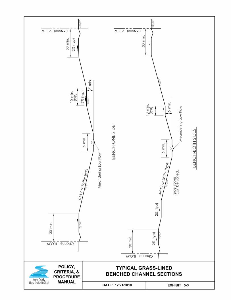
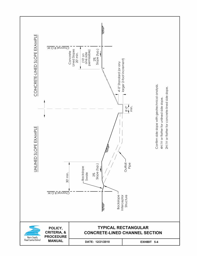
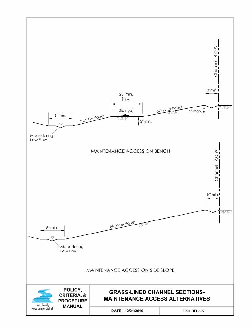


12/21/10 Update
Harris County Flood Control District Policy, Criteria, and Procedure Manual 6-1
SECTION 6 - STORMWATER DETENTION BASINS
6.1 Introduction
When to Use 6.1.1
Use stormwater detention basins:
To reduce flood risks.
To limit peak flow rates to pre-development or pre-project rates.
In conjunction with channel conveyance improvements so flood levels downstream of the project do not increase.
Where Not Required 6.1.2
Stormwater detention basins are not required:
Where system capacity exists for the new development as determined by the HCFCD and accepted by Harris County Commissioners Court.
For only one single family residence where no major changes in existing conditions are proposed and it is not part of a larger development project.
For developments less than or equal to one acre.
For redevelopment projects that do not increase the amount of impervious cover or the runoff from the site.
Terminology 6.1.3
Detention basin definitions used in this manual are presented in Appendix E, Terminology. Exhibit 6-1 illustrates an on-line detention basin, off-line detention basin, on-site detention basin, and in-line detention storage.
In-line Detention Storage 6.1.4
In-line detention is permissible within a HCFCD channel only when:
The proposed development is located at the headwaters of a watershed or sub-area and no other landowners drain into the in-line facility.
Multiple landowners of proposed developments located at the headwaters of a watershed or sub-area execute an agreement to mutually utilize an in-line facility and no other landowners drain into it.
It is part of a HCFCD approved regional or subregional plan.
An existing HCFCD maintained channel is already an in-line detention facility.
Note: Use channel design criteria for in-line detention basins.

12/21/10 Update
Harris County Flood Control District Policy, Criteria, and Procedure Manual 6-2
6.2 Design Procedure
Design Procedure 6.2.1
A suggested procedure for designing a gravity detention basin is given in the table below. Location and general layout considerations and criteria are in Section 6.3, General Design Criteria and Section 6.4, Layout. For developments less than 50 acres, some steps are simplified (see Section 6.10, Method 1 – Small Project Drainage Areas).
Step Action
1 Select a location and prepare a general layout for the detention basin.
2 Determine the inflow hydrographs and maximum allowable outflow rates.
3 Establish the maximum allowable water elevation in the basin and determine tailwater condition in the outfall channel.
4 Estimate the detention volume needed and size the outflow structure. Determine the relationship between storage, discharge, and elevation.
5 Route the design 1% exceedance inflow hydrograph through the basin and outflow structure with appropriate tailwater condition.
6 Adjust the detention volume and outflow structure, if necessary, until the allowable 1% exceedance outflow rate is not exceeded and the detention basin fills to or near the design maximum allowable water surface elevation.
7 Route the 10% exceedance hydrograph through the facility and make appropriate adjustments to the outflow structure. Route other frequencies, as appropriate, and make adjustments, as necessary. Re-check the 1% exceedance event if changes are made to the outflow structure.
8 Verify storm sewers, street drainage, and channels entering the basin will function as intended, relative to the design water levels in the detention basin.
9 Provide an emergency spillway or overflow structure for an extreme rainfall event or in the event of a blocked outfall pipe.
10 Investigate potential geotechnical and structural problems and establish an erosion control plan.
11 Establish the right-of-way limits, including access for maintenance and space for multi-use.

12/21/10 Update
Harris County Flood Control District Policy, Criteria, and Procedure Manual 6-3
6.3 General Design Criteria
Overview 6.3.1
A gravity detention basin’s location, size, and layout are influenced by the physical features of the site, the type of development proposed, the receiving stream’s characteristics, the storage volume needed, and the detention basin’s other uses. This section covers general criteria and subsequent sections cover criteria for specific features.
Considerations 6.3.2
Factors to consider when locating a detention basin:
Overland and storm sewer flow to the detention basin. (Preferred location of the basin is the lowest area of the property.)
Effect of the detention basin function with respect to the flood plain. (For detention basins in a flood plain, consider factors such as backwater elevation, inundation timing versus site runoff timing, and inundation duration).
Other factors listed in Section 6.4.1, Overview.
Design Frequencies 6.3.3
Design new detention facilities to detain the 10% and 1% exceedance probability, 24-hour storm events for proposed watershed conditions.
When detention basin modifications are necessary to accommodate a proposed storm sewer outfall or a proposed development, design the modifications such that the 10% and 1% exceedance probability water surface profiles in the detention basin and downstream channels are not increased above existing conditions.
Note: If a downstream channel has less than a 10% exceedance probability capacity, also design for the frequency when the channel is flowing full or at its flooding threshold. HCFCD has flooding threshold data.
Outflow Rates 6.3.4
To comply with local regulations and HCFCD policy to avoid adverse impacts, maximum allowable outflow rates from detention basins are restricted to the pre-development 10% and 1% exceedance probability, 24-hour events.
If a downstream channel has less than a 10% exceedance probability capacity, also restrict the outflow to the amount the pre-development project site contributes to the channel when it is flowing full or at its flooding threshold.
If the outflow is into a roadside ditch or storm sewer, restrict the maximum allowable outflow to the rate allowed from the proposed site development using criteria adopted by the jurisdiction responsible for the roadside ditch or storm sewer.
Continued on next page

12/21/10 Update
Harris County Flood Control District Policy, Criteria, and Procedure Manual 6-4
6.3 General Design Criteria, Continued
Hydraulic Features 6.3.5
Hydraulic features typically constructed within a detention basin are listed in the table below. Criteria for the hydraulic features are presented in the sections indicated in the table below.
Hydraulic Feature Section
Backslope Drainage System 11.1
Inflow Structures 6.6
Outflow Structures 6.7
Pipe Outfalls 11.3
Layout 6.4
Geotechnical Investigations 6.3.6
A geotechnical investigation is required for all work in existing and proposed new HCFCD maintained detention basins and proposed work that deepens or enlarges an existing HCFCD detention basin. Previous investigations can be utilized, if applicable to the proposed project and the following design topics are addressed.
As a minimum, address the following:
Stability of the basin side slopes for short term and long term conditions. (If basin depth ≤ 5 feet, a slope stability analysis is not required.)
Stability of the deep pool side slopes.
Evaluation of bottom instability due to excess hydrostatic pressure.
Control of groundwater.
Identification of dispersive soils.
Potential erosion problems.
Constructability issues.
Evaluation of inflow and outflow structures.
Follow the geotechnical investigation requirements as provided in HCFCD’s Geotechnical Investigation Guidelines in Appendix D.
Water Quality Features 6.3.7
Water quality features placed in a HCFCD maintained detention basin are covered in Section 16, Water Quality Features.
Continued on next page

12/21/10 Update
Harris County Flood Control District Policy, Criteria, and Procedure Manual 6-5
6.3 General Design Criteria, Continued
Tree and Shrub Plantings 6.3.8
Planting trees and shrubs in a HCFCD maintained detention basin is acceptable to the HCFCD without accounting for their volume provided criteria and procedures are followed in Section 18, Environmental, Recreation, and Aesthetic Features and Section 2.2.7, Non-Flood Control Features Accepted in a HCFCD facility.
Environmental Investigations 6.3.9
Compliance with appropriate federal, state, and local environmental rules, laws, regulations, and permits is required when modifying or constructing HCFCD facilities (see Section 17, Environmental and Archeological Compliance).
Maintenance Access Plan 6.3.10
For new detention basins, submit a maintenance access plan with the drainage or design report, or the construction drawings.
For detention basin modifications, update the maintenance access plan reflecting any changes needed due to the proposed modification.
Drain Time 6.3.11
Empty detention basins in 24 hours, when possible. Maximum drain time is 48 hours (2 days), unless the maximum outflow rate results in a longer drain time such as a pumped basin or a watershed diversion. Measure drain time from the peak design detention volume to the 90% drained volume or the stormwater quality volume.
It is not necessary to consider backwater from the outfall channel when calculating drain time.
If drain time is longer than 48 hours, use rainfall amount and increase in detention volume that approximates the drain time as shown the table below.
Duration Total Rainfall Increase in Detention
Volume
1 Day 13.2” 0%
3 Day* 15.3” 5%
4 Day 16.1” 10%
* 3 day value interpolated.

12/21/10 Update
Harris County Flood Control District Policy, Criteria, and Procedure Manual 6-6
6.4 Layout
Overview 6.4.1
Layout of a detention basin is influenced by many factors, such as:
Topography.
Volume needed.
Grading and depth requirements.
Geometric design criteria.
Existing and future roads, pipelines, and utilities.
Location of inflow, outflow control, and emergency overflow structures.
Maintenance access requirements.
Environmental features.
Soil and groundwater conditions.
Owner designated features.
This section focuses on the geometric design factors influencing the detention basin size, depth, side slopes, and bottom design.
Depth 6.4.2
The depth of a gravity detention basin is usually determined by the depth of the outfall channel, roadside ditch, or storm sewer. In some cases, the depth may be determined by the depth of the inflow channel or storm sewer, groundwater level, or soil conditions.
For deep and shallow pools, see Section 6.4.11, Wet Bottom Design
For pumped detention systems, see Section 6.15, Pump Detention Systems.
Side Slopes 6.4.3
For detention basin side slopes:
For grass-lined slopes, the steepest side slope allowed is 3(horizontal):1(vertical) for long term stability and maintenance. (See Section 6.3.6, Geotechnical Investigations.)
For concrete-lined slopes, follow the recommendations in this manual regarding concrete-lined channels.
Typical Sections 6.4.4
Typical detention basin sections are shown in Exhibit 6-2.
See Section 6.5.4, Minimum Berm Widths for maintenance access and minimum berm widths.
Continued on next page

12/21/10 Update
Harris County Flood Control District Policy, Criteria, and Procedure Manual 6-7
6.4 Layout, Continued
Bottom Design – Introduction 6.4.5
The detention basin bottom impacts a basin’s long-term maintenance, aesthetics, and multi-use. The bottom design affects the detention basin depth, volume, and surface area.
The bottom can be designed to either be dry, wet, or a combination of wet and dry between periods of inundation, depending on the desired use and maintenance requirements.
Dry Bottom Design 6.4.6
A well-graded bottom incorporating pilot channels and good cross slopes is required to facilitate routine mowing and complete drainage of a basin following a runoff event. This is referred to as a dry bottom.
Criteria for a well-graded (or dry) bottom are presented in the table below and shown in Exhibits 6-2 and 6-3.
Feature Criteria Outfall Pipe Outlet Invert For flat bottom channels, one foot above
channel flowline or one foot above the normal water surface, whichever is higher. For channels with center depression, use table in Section 5.4.3, Bottom Configuration-Trapezoidal Grass-Lined.
Inlet Invert A minimum of 0.5 foot above outlet invert and minimum 3 feet per second velocity when hydraulic gradient = flowline gradient.
Pilot Channel
Starting Flowline
At outfall pipe inlet invert. If no outfall pipe, a minimum of 1.5 feet above the receiving channel flowline or normal water surface.
Flowline Gradient
Grass - Minimum 0.002 feet per foot (0.2%). Concrete – Minimum 0.001 feet per foot (0.1%)
Depth One-foot minimum Side Slope Grass lined – 5:1 to 3:1
Concrete lined – 10:1 to 3:1 Concrete
Grade Control Structures
Use at intersections with wetlands, deep pools, and other pilot channels. Base design on the interceptor structure standard detail.
Location A minimum of 20 feet away from the toe of the basin side slope.
Inflow Pipe Invert At or up to 1 foot above pilot channel flowline Transverse or cross slopes Minimum 0.01 feet per foot (1%).
Continued on next page

12/21/10 Update
Harris County Flood Control District Policy, Criteria, and Procedure Manual 6-8
6.4 Layout, Continued
Wet Bottom Design – Introduction 6.4.7
The use of a wet bottom, such as a permanent water pool and/or shallow pool, is permissible provided a sponsor agrees to maintain the features HCFCD will not maintain listed in Section 2.2.5, Typical Non-Flood Control Features, and comply with the conditions in Section 2.2.7, Non-Flood Control Features Allowed in a HCFCD Facility.
The wet bottom can be used in combination with a dry bottom. The HCFCD will maintain the dry bottom portion provided compliance with the conditions in Section 2.2.3, Acceptance for HCFCD Maintenance.
Wet detention basin bottom features are described below.
Shallow Pool 6.4.8
The purpose of a shallow pool is to support aquatic plants and habitat, and improve water quality. Water in shallow pool areas may not be permanent.
HCFCD will not maintain dry basins with wet pilot channels. HCFCD discourages wet bottoms consisting only of shallow pools.
A shallow pool can be incorporated around the edge of a deep pool. See Section 18.2, Environmental Features, for additional information on shallow pools. HCFCD will maintain a deep and shallow pool combination provided it is not a water quality feature.
Deep Pool 6.4.9
The purpose of a deep pool is to:
Provide open water for aesthetics.
Reduce vegetation management costs in larger detention basins.
Support benthic and fish habitats that help sustain a healthy pond.
Improve water quality.
Provide fishing opportunities.
A deep pool cannot be used alone. The bottom shelf must be used in conjunction with the deep pool.
Bottom Shelf 6.4.10
The purpose of the bottom shelf is to:
Reduce the risk of people (children) running or rolling down a slope into the water.
Improve the aesthetics around a permanent deep pool.
Provide vehicular access around the permanent deep pool or shallow pool.
A bottom shelf is required around both deep and shallow pools.
Continued on next page

12/21/10 Update
Harris County Flood Control District Policy, Criteria, and Procedure Manual 6-9
6.4 Layout, Continued
Wet Bottom Design 6.4.11
Criteria for a wet bottom are presented in the table below and shown in Exhibits 6-2 and 6-4.
The minimum water surface area for a permanent deep pool and shallow pool in a HCFCD maintained facility is one acre.
Feature Criteria
Outfall Pipe Outlet Invert Same as Section 6.4.6, Dry Bottom Design
Inlet Invert Same as Section 6.4.6, Dry Bottom Design
Visible for inspection and maintenance from at least one end of the pipe
Risers Inlet Visible for inspection and maintenance
Inflow Pipe Outlet End Into Basin
Use criteria of the entity responsible for the inflow pipe. If HCFCD, visible for inspection and maintenance and use criteria in Section 6.6.5, Pipe Outfalls on a Bottom Shelf.
Bottom Shelf Height 1 foot above static water surface
Cross slope Minimum 0.02 feet per foot (2.0%)
Width Minimum10 feet
Deep Pool Depth Minimum 6 feet; Maximum depends on soils, geometry, and habitat goals
Side Slope No steeper than 3:1 (see Section 6.4.3, Side Slopes)
Bottom Slope Flat
Shallow Pool Depth 0 – 18 inches
Bottom Slope Flat or mild slope
Water Edge Walls 6.4.12
Walls at the water’s edge (bulkheads) are permissible under the following conditions:
An entity other than HCFCD agrees to maintain the walls at the water’s edge. They are a non-flood control feature.
A bottom shelf is included with the water edge wall.
Continued on next page

12/21/10 Update
Harris County Flood Control District Policy, Criteria, and Procedure Manual 6-10
6.4 Layout, Continued
Maintenance Access Alternative - Bench 6.4.13
For grass-lined detention basins, maintenance access can be on a bench as shown on Exhibit 6-5. Criteria is:
Place bench at least 5 feet above the toe of slope and no more than 5 feet below the top of bank.
Minimum bench width – 20 feet.
Minimum bench cross slope toward basin – 2%.
Side slope above the bench is no steeper than 5:1.
Include 20-foot wide ramps back to natural ground at road crossings and all maintenance access points at a gradient no steeper than 7% (14:1).
A backslope drainage system is required unless one of the exceptions in Section 11.1.2, Where to Use, applies.
Top of slope must be a minimum of 10 feet from the right-of-way line.
Note: Design storm sewer pipes, inflow and outflow pipes, and backslope drainage pipes to cross under the maintenance access bench.
Maintenance Access Alternative – Gentle Slope 6.4.14
For grass-lined side slopes no steeper than 8:1, maintenance access can be along the slope itself (see Exhibit 6-5). However, all weather access roads cannot be located on the 8:1 side slope. See Section 16.3, Design Criteria.
Water Quality Feature Access 6.4.15
For maintenance access requirements to water quality features, see Section 16.3, Design Criteria.

12/21/10 Update
Harris County Flood Control District Policy, Criteria, and Procedure Manual 6-11
6.5 Right-of-Way
Overview 6.5.1
This section provides criteria and guidelines for determining the right-of-way or public drainage easement limits for a detention basin maintained by HCFCD.
The dedication and conveyance process is presented in Section 15, Right-of-Way.
Right-of-Way Limits 6.5.2
HCFCD detention basins require right-of-way to contain the basin, maintenance access around the basin, backslope drainage systems if included, and maintenance access from public roads or HCFCD channel.
The right-of-way limits for a typical detention basin to be maintained by HCFCD are:
The area within the top of bank plus,
Twenty feet for maintenance access plus,
Ten feet for the backslope swale system, where used.
Exceptions:
See Section 5.5.6, Adjacent HCFCD Channel and HCFCD Detention Basin
See Section 6.4.13, Maintenance Access Alternative – Bench.
See Section 6.4.14, Maintenance Access Alternative – Gentle Slope.
See Section 11.1.2, Where To Use, for conditions where backslope swale systems are not needed.
Use field survey data and detention basin profile to determine the limits of the detention basin top of bank.
Continued on next page

12/21/10 Update
Harris County Flood Control District Policy, Criteria, and Procedure Manual 6-12
6.5 Right-of-Way, Continued
Minimum Berm Widths 6.5.3
Minimum berm widths around a detention basin are shown on typical sections in Exhibits 6-2 and 6-5, and presented in the table below.
1 Backslope swale system not needed. 2 Maintenance access is on the side slope
Detention Basins That Are The Minimum Berm Width Is
Grass-lined with a depth > 7 feet 30 feet
Grass-lined with a depth ≤ 7 feet 20 feet1
Grass-lined where side slopes are 8(horizontal):1(vertical) or flatter
10 feet2
Grass-lined with the 20-foot maintenance access on a bench
10 feet
Lined with riprap or articulated concrete blocks or partially concrete-lined
Same as grass-lined channel
Fully concrete-lined 20 feet1
HCFCD Detention Basins Adjacent to Channels or Roads 6.5.4
See Sections 5.5.6 and 5.5.8 for berm widths and right-of-way criteria where HCFCD detention basins are located adjacent to a HCFCD channel or road.

12/21/10 Update
Harris County Flood Control District Policy, Criteria, and Procedure Manual 6-13
6.6 Inflow Structures
Inflow 6.6.1
Stormwater run-off enters off-stream detention basins through storm sewer pipes, backslope swale pipes, ditches, and/or overland. Normal hydrologic analysis is performed for calculating the inflow rate.
Design the storm sewer and overland flow system to convey the 1% storm event into the detention basin.
Inflow Structures 6.6.2
For overland inflow, see Section 13.2, Extreme Event Overland Flow Swales.
For storm sewer pipe inflow, see Section 11.3, Pipe Outfalls.
For storm sewer and backslope drainage inflow pipes, see Section 6.6.5, Pipe Outfalls on a Bottom Shelf.
For submerged inflow pipes or boxes, see Section 11.3.5, Submerged Inflow Pipes.
For HCFCD detention basins, do not locate inflow structures in the corner of the basin.
Side-Weir 6.6.3
When a delay in filling the detention basin is desired until the water in the channel reaches a certain level, an inflow structure referred to as a side-weir can be used. This approach:
Keeps the detention basin from being inundated from the smaller, more frequent storms that do not result in flooding.
Reserves the detention volume for later in a severe storm event when the volume is more effective at reducing peak flows.
Can require less stormwater volume and land than a conventional flow-through facility.
For analysis, modeling, and design of side weirs, contact HCFCD staff for consultation and latest analytical tools and guidance. Note: Whether a side-weir or flow-through is used depends on where the detention basin is located in the watershed and where the area of flood level reduction is located. If the area of flood level reduction is hydraulically close to the detention basin, a side-weir is usually more efficient.
Continued on next page
12/21/10 Update
Harris County Flood Control District Policy, Criteria, and Procedure Manual 6-14
6.6 Inflow Structures, Continued
Erosion Control 6.6.4
High velocities and turbulence can occur at inflow pipes. Use structural erosion control measures, as needed, such as concrete lining, riprap, or articulated concrete blocks.
Use concrete lining for protection at weir structures. Adequate coverage, thickness, reinforcement, and toe walls must be designed for each structure. Riprap can be used to transition to a grass-lined channel or detention basin.
Articulated concrete blocks and riprap can be used in place of concrete lining at weirs, except where high velocities and turbulence are expected.
Pipe Outfalls on a Bottom Shelf 6.6.5
For storm sewer or offsite ditch interceptor pipes that outfall on a grass-lined bottom shelf (see Section 6.4.10, Bottom Shelf), include a swale from the pipe to the deep or shallow pool.
Swale criteria is:
6 inches deep.
Flowline gradient = same as bottom shelf cross slope (typically 2%).
Minimum top width = 4 x pipe diameter.
Center on pipe.
Line with articulated concrete blocks, 3”-5” granular material, concrete lining, or other acceptable material for the flow condition anticipated.
Cover lining with minimum 6” top soil and vegetate.
Extend lining a minimum of 5 feet beyond edge of bottom shelf into deep or shallow pools.
Note: Backslope drain pipes do not require a swale across the bottom shelf.

12/21/10 Update
Harris County Flood Control District Policy, Criteria, and Procedure Manual 6-15
6.7 Outflow Structures
Common Structures 6.7.1
Common structures used to restrict outflow from a gravity flow detention basin are pipes, box culverts, risers, and weirs. The numbers, sizes, and elevations can be varied to control outflows for different storm frequencies.
Several equations and computer programs are available to compute flows and head losses through pipes, boxes, and weirs. Pipe, box culvert, and weir equations for outlet control conditions are presented below.
Pipe Equation 6.7.2
For a round pipe flowing full with both the entrance and exit submerged, the head loss equation is:
100
Q
D
Ln466
D
k152.2H
22
4 316
e Pipe Culvert Head Loss Equation
where: H = head difference between entrance and exit in feet
ke = entrance loss coefficient (see Section 6.7.4, Entrance Loss Coefficients)
D = diameter of pipe in feet
n = Manning's roughness coefficient (0.024 for a corrugated metal pipe and 0.013 for a concrete pipe)
L = length of pipe in feet
Q = design discharge rate in cubic feet per second
Box Culvert Equation 6.7.3
For a box culvert flowing full with both the entrance and exit submerged, the head loss equation is:
34
222
2.21R
LnV
2
V)k0.1(H
ge Box Culvert Head Loss Equation
where: H = head difference between entrance and exit in feet
ke = entrance loss coefficient (see Section 6.7.4, Entrance Loss Coefficients)
V = velocity in the culvert in feet per second = discharge/culvert area
g = acceleration due to gravity (32.2 feet per second2)
n = Manning's roughness coefficient (0.013 for a concrete box)
L = length of box in feet
R = hydraulic radius of culvert in feet = culvert area/wetted perimeter
Continued on next page

12/21/10 Update
Harris County Flood Control District Policy, Criteria, and Procedure Manual 6-16
6.7 Outflow Structures, Continued
Entrance Loss Coefficients 6.7.4
Entrance loss coefficients, ke, for common entrances are:
Sharp, projecting corrugated metal pipe...…………………..0.9 Square edge pipe or culvert with headwall…...…….……….0.5 Well rounded edge, tapered wingwalls……………………...0.2
See the FHWA, Hydraulic Design Series No. 5, Hydraulic Design of Highway Culverts (1985), for a complete list of entrance loss coefficients.
Minimum Pipe Size 6.7.5
To reduce the chance of clogging and improve the chance a detention basin will work when needed and as designed, minimum pipe size restrictors are as designated by local jurisdiction where detention basin is located (typically Harris County or City of Houston).
For detention facilities discharging into a HCFCD maintained facility, the minimum outfall pipe size within the HCFCD maintained facility is 24 inches. If a restrictor smaller than 24 inches is needed, place a short section of the smaller pipe or a plate in the larger pipe at a visible location outside the HCFCD right-of-way. Locate the restrictor to facilitate inspection and debris removal.
Continued on next page

12/21/10 Update
Harris County Flood Control District Policy, Criteria, and Procedure Manual 6-17
6.7 Outflow Structures, Continued
Orifice Equation 6.7.6
To restrict the outflow with a short segment of pipe or reduced opening size, use the orifice equation below. For other configurations, see Brater and King’s Handbook of Hydraulics or other applicable references.
gHCAQ 2
where: Q = discharge in cubic feet per second C = coefficient of discharge
– 0.8 for short segments of pipe – 0.6 for openings in plates, standpipes, or concrete walls
A = area of opening in square feet g = acceleration due to gravity (32.2 feet/second2)
H = head difference between entrance and exit in feet when orifice is fully submerged, or the difference between the water surface elevation at the entrance and the centroid of the orifice in feet when orifice is partially submerged.
Outflow Structures 6.7.7
For pipe outflow structures in HCFCD maintained channels:
Use corrugated metal or HDPE pipes (see Section 11.3, Pipe Outfalls).
Include concrete lining around the pipe if soil and velocity conditions warrant it (see Appendix D, HCFCD Concrete Lining Standard Detail).
For box culverts or reinforced concrete pipe, use a headwall in the basin and a headwall recessed into the HCFCD channel that does not disrupt the flow in the channel. Design and construct the box culvert and headwall in accordance with TxDOT or Harris County criteria.
Backflow Preventers 6.7.8
Backflow preventers are acceptable provided they:
Are above the normal water surface.
Do not project into the channel flow.
Can be easily accessed to remove debris.
See Section 11.3.3, Backflow Preventers
Seepage 6.7.9
Seepage around pipe or box outflow structures can be a significant problem due to the potential high head differential between the channel and detention basin. Carefully construct with sufficient compaction of the backfill material around the pipes or boxes as recommended by the geotechnical engineer.
Continued on next page

12/21/10 Update
Harris County Flood Control District Policy, Criteria, and Procedure Manual 6-18
6.7 Outflow Structures, Continued
Weirs 6.7.10
Weirs can be used to control the design outflow or the emergency overflow from a detention basin. Weirs are sometimes used as an inflow structure, also.
The rectangular weir equation is:
Q = CLH3/2
where: Q = weir discharge in cubic feet per second C = weir coefficient L = horizontal length of weir in feet H = head on weir in feet
The value of the weir coefficient, C, depends on the weir shape (for example, broad crested or sharp crested) and if the weir is submerged or not. See Brater and King’s Handbook of Hydraulics or other applicable references.
Erosion Control 6.7.11
High head differentials and erosive velocities for prolonged periods of time can occur at pipe inlets. Use concrete lining or riprap around pipe inlets where erosive velocities and turbulence are expected.
Flow from the outflow structure can cause erosion in the outfall channel due to high velocities and turbulence. See Section 10, Erosion and Sediment Control for specific erosion control guidelines and criteria.
Use concrete lining for weirs. Design coverage, thickness, reinforcement, and toe walls for each structure. Riprap, articulated concrete blocks, or other similar material can be used where the chance of turbulence is low.
Multiple Frequency Outflow Structures 6.7.12
Maximum allowable outflow rates are restricted to pre-development 10%, and 1% exceedance probability discharges, and in some cases, a more frequent event associated with the bankfull capacity of the outfall channel (see Section 6.3.4, Outflow Rates). If a water quality improvement feature is also included, then there is also outflow control for high frequency rainfall events (see Section 16, Water Quality Features).
Typical multiple frequency outflow control structures generally consist of pipes or boxes of various sizes at different elevations or a riser and an emergency overflow weir.

12/21/10 Update
Harris County Flood Control District Policy, Criteria, and Procedure Manual 6-19
6.8 Tailwater
Overview 6.8.1
The water surface elevation in the outfall channel at the outflow structure is the tailwater. The tailwater affects both the outflow structure design and the stage-outflow relationship of the detention basin.
To facilitate analysis and design of detention basins, two tailwater assumptions are possible:
Fixed.
Variable.
Note: Specific criteria are provided for each of the three methods for determining detention volume.
Backwater 6.8.2
Near channel confluences and in coastal zones, backwater can occur that is higher than the tailwater from the flow in the channel itself. Consider the backwater in designing the emergency overflow and establishing design water levels in the detention basin and proposed development.

12/21/10 Update
Harris County Flood Control District Policy, Criteria, and Procedure Manual 6-20
6.9 Detention Volume
Overview 6.9.1
Determining the stormwater detention volume for a small development project or a complex large development project requires use of the same hydrologic and hydraulic principles. However, different methodologies are presented in this section which recognizes sizes of projects and levels of complexity to facilitate the analytical and design process.
Methods 6.9.2
Where detention is required in watersheds or portions of watersheds, the three methods to determine the detention volume are listed below and covered in detail in subsequent sections. Each method addresses the inflow, allowable outflow, and tailwater conditions.
Method For Project Drainage Areas
1 Small Less than 50 acres
2 Moderate Between 50 acres and 640 acres
3 Large Greater than 640 acres
Roadway Only Method 6.9.3
Due to the potential impact of new and improved road projects on overland flow patterns and stormwater runoff, an alternative method for analyzing and sizing mitigation for roadways only is presented in Section 6.16, Roadway Impacts and Mitigation.
Continued on next page

12/21/10 Update
Harris County Flood Control District Policy, Criteria, and Procedure Manual 6-21
6.9 Detention Volume, Continued
Minimum Detention Volume 6.9.4
Minimum detention volumes are:
The volume calculated using Method 1 or 2 (Section 6.10 and 6.11), but not less than 0.55 acre-feet per acre of new development or as defined in a watershed or sub-watershed with an adopted regional or master plan.
The volume calculated using the Optional Project Routing Technique (Section 3.7), but not less than 0.45 acre-feet per acre of new development or as defined in a watershed or sub-watershed with an adopted regional or master plan.
The volume calculated by conducting a hydrologic and hydraulic analysis along the entire length of the main channel using Method 3, Watershed Modeling Method (Section 6.12), but not less than 0.45 acre-feet per acre of new development or as defined in a watershed or sub-watershed with an adopted regional or master plan.
For new developments with limited on-site drainage improvements and relatively small amounts of impervious cover (less than or equal to 15%), the volume calculated using Method 1, 2, or 3, but not less than 0.35 acre-feet per acre of new development.
For pumped detention facilities, see Section 6.15, Pumped Detention Systems.
Note: The area of new development is based on the area of the property, not just the impervious cover area. See Section 3.5, Impervious Cover, for a generalized relationship between impervious cover and land development.
What to Include 6.9.5
Include only the storage volume below the detention basin design water surface elevation in the detention basin itself and storm sewers and open channels discharging into the detention basin.
Storage volume in streets above the detention basin design water surface calculated in dynamic hydrologic and hydraulic models cannot be included in the detention storage volume.
Include only the storage volume above the normal pool elevation for detention basins with a permanent deep pool or wetland.
Do not include storage volume used to mitigate flood plain fill.
Do not include storage volume in an existing flood plain.

12/21/10 Update
Harris County Flood Control District Policy, Criteria, and Procedure Manual 6-22
6.10 Method 1 – Small Project Drainage Areas
When to Use 6.10.1
For projects with drainage areas less than 50 acres, Method 1 is recommended. Some of the steps presented in Section 6.2, Design Procedure, are simplified to facilitate the design process for these smaller sites.
Inflow 6.10.2
No inflow hydrograph or discharge is calculated.
Maximum Allowable Outflow 6.10.3
Maximum allowable outflow criteria are in Section 6.3.4, Outflow Rates.
For HCFCD maintained channels, use:
The Site Runoff Curves (Exhibits 3-1 and 3-2) to determine the maximum outflow rate for the 10% and 1% exceedance probabilities.
The amount of flow the project site contributes to the bankfull capacity of the outfall channel.
For roadside ditches or storm sewers, use the methodology adopted by the agency responsible for the roadside ditch or storm sewer to determine the maximum outflow rate.
Tailwater 6.10.4
Tailwater is not used to determine the detention volume in Method 1, but it is used to size the outflow structure.
Use the top of pipe in the outfall channel as a fixed tailwater condition.
Since hydrographs are not used in Method 1, variable tailwater is not used.
Detention Volume 6.10.5
Use the minimum detention storage volume designated in Section 6.9.4, Minimum Detention Volume.
For most small projects, it will be 0.55 acre-feet per acre of new development.
Continued on next page

12/21/10 Update
Harris County Flood Control District Policy, Criteria, and Procedure Manual 6-23
6.10 Method 1 – Small Project Drainage Areas, Continued
Outflow Structure 6.10.6
Using the maximum allowable outflow rate and applicable tailwater condition, size the outflow structure using the appropriate equations and information in Section 6.7, Outflow Structures.
For the 1% exceedance probability outflow structure, use the design water surface in the detention basin based on 0.55 acre-feet per acre volume.
For the 10% exceedance probability outflow structure, use the design water surface in the detention basin based on 0.33 acre-feet per acre volume.
Optional Project Routing Technique 6.10.7
The Optional Project Routing Technique (Section 3.7) may be used for calculating detention volume and sizing the outflow structure.
Documentation 6.10.8
Include assumptions, justifications, calculations, and sketches on the construction drawings or in the drainage report submittal to HCFCD (see Section 19, Report Requirements).

12/21/10 Update
Harris County Flood Control District Policy, Criteria, and Procedure Manual 6-24
6.11 Method 2 – Moderate Project Drainage Areas
When to Use 6.11.1
For projects with drainage areas between 50 and 640 acres, Method 2 is recommended. Some of the steps presented in Section 6.2, Design Procedure, are simplified to facilitate the design process for moderate size sites.
Use Method 2 only if correlation with existing HEC-HMS or HEC-RAS modeling on the outfall channel is not necessary. If correlation is necessary, use Method 3.
Inflow 6.11.2
Use the Small Watershed Method presented in Section 3.6, Small Watershed Hydrograph Method, to develop hypothetical inflow hydrographs for each of the design exceedance probabilities.
Determine peak inflow rates using the Site Runoff Curves for areas between 50 and 640 acres for the 10% and 1% exceedance probabilities (Exhibits 3-1 and 3-2).
Maximum Allowable Outflow 6.11.3
Maximum allowable outflow criteria are in Section 6.3.4, Outflow Rates.
For HCFCD maintained channels, use:
The Site Runoff Curves (Exhibits 3-1 and 3-2) to determine the maximum outflow rate for the 10% and 1% exceedance probabilities.
The amount of flow the project site contributes to the bankfull capacity of the outfall channel.
For roadside ditches or storm sewers, use the methodology adopted by the agency responsible for the roadside ditch or storm sewer to determine the maximum outflow rate.
Tailwater 6.11.4
Since a hypothetical inflow hydrograph is used that does not have any correlation with the outfall channel hydrograph, a variable tailwater based on an existing watershed model is not used.
Use the top of outlet pipe in the outfall channel as a fixed tailwater condition for the 10% and 100% exceedance probabilities analysis.
Continued on next page

12/21/10 Update
Harris County Flood Control District Policy, Criteria, and Procedure Manual 6-25
6.11 Method 2 – Moderate Project Drainage Areas, Continued
Outflow Structure – Preliminary Size Estimate 6.11.5
Using the maximum allowable outflow rate and applicable tailwater condition, determine a preliminary size of the outflow structure using the appropriate equations and information in Section 6.7, Outflow Structures.
Detention Volume and Outflow Structure 6.11.6
Follow steps 5 – 12 in Section 6.2.1, Design Procedure to determine the detention volume and final outflow structure size and configuration.
The minimum detention volumes designated in Section 6.9.4, Minimum Detention Volume, apply.
To route the inflow hydrographs through the detention basin, a standard reservoir routing procedure is recommended.
Note: The reservoir routing procedure requires the development of stage versus storage and stage versus outflow relationships.
Optional Project Routing Technique 6.11.7
The Optional Project Routing Technique (Section 3.7) may be used for calculating detention volume and sizing the outflow structure.
Alternative Models 6.11.8
In some cases, a standard reservoir routing procedure may be difficult to use or not be applicable. For example, multiple detention basins in series that are hydraulically dependent or an unconventional control structure. Applicable alternative models can be used. Inform HCFCD early in the review process of the computer model that will be used and provide model documentation, if required, to facilitate the review.
Documentation 6.11.9
Include assumptions, justifications, calculations, summary tables, profiles, hydrographs, and sketches in the drainage report submitted to HCFCD. See Section 19, Report Requirements for a list of requirements.

12/21/10 Update
Harris County Flood Control District Policy, Criteria, and Procedure Manual 6-26
6.12 Method 3 – Large Project Drainage Areas
When to Use 6.12.1
Use Method 3 for projects:
With drainage areas greater than 640 acres, or
Where correlation with existing HEC-HMS or HEC- RAS is necessary, or
Where definition or modification of effective FEMA regulatory flood plains or floodways is necessary, or
Where complexity of the project justifies a detailed analysis for a drainage area greater than 300 acres and less than 640 acres.
Analysis 6.12.2
A detailed hydrologic and hydraulic analysis is required utilizing HEC-HMS and HEC-RAS using the current Watershed Modeling Method (see Section 3.4, Watershed Modeling Method).
Use the above referenced models to determine the following:
Inflow hydrographs.
Maximum allowable outflow rates.
Variable tailwater conditions.
Detention volume requirements.
Outflow structure configuration and sizes.
The minimum detention volumes designated in Section 6.9.4, Minimum Detention Volume, apply.
Alternative Models 6.12.3
In some cases, HEC-HMS and HEC-RAS cannot accurately simulate some projects or detention basin conditions. For example, multiple detention basins in series that are hydraulically dependent or an unconventional control structure. It is acceptable to use inflows from HEC-HMS as input into special programs, such as detention basin routing programs. The outflows from the special programs can then be inserted back into HEC-HMS to analyze the effects on the channel.
Documentation 6.12.4
Include assumptions, justifications, summary tables, profiles, hydrographs, computer runs, and sketches in the drainage report submitted to HCFCD. See Section 19, Report Requirements for a list of requirements.

12/21/10 Update
Harris County Flood Control District Policy, Criteria, and Procedure Manual 6-27
6.13 Emergency Overflow
Criteria 6.13.1
An emergency overflow structure or route is required for all detention basins.
Design the emergency overflow as a path for the water to follow when water levels exceed the 1% exceedance probability design water level in the detention basin.
Locate the emergency overflow such that when the flow leaves the detention facility, impacts on existing flood levels and nearby structures are minimized.
Considerations 6.13.2
Consider water levels relative to the houses and businesses when designing the emergency overflow.
Consider the natural flow pattern when locating the emergency overflow path.
Avoid placing the emergency overflow on fill which is easily eroded.
Use the criteria presented in Section 13, Extreme Event Overflow in designing emergency overflow weirs.

12/21/10 Update
Harris County Flood Control District Policy, Criteria, and Procedure Manual 6-28
6.14 Erosion Control
Criteria 6.14.1
Establish permanent turf grass on all exposed or disturbed soil in a detention basin except where structural erosion protection, wetlands, or permanent pools are located (see Section 10.3, Turf Establishment).
Use structural measures such as concrete lining, riprap, articulated concrete blocks, or similar materials where excessive velocities or turbulence are expected (see Section 4.4, Velocities; Section 10, Erosion and Sediment Control; Section 6.6, Inflow Structures; and Section 6.7, Outflow Structures).
Backslope Swales 6.14.2
Backslope drainage systems are required where the natural ground slopes toward the detention basin (see Section 11.1, Backslope Drainage Systems).

12/21/10 Update
Harris County Flood Control District Policy, Criteria, and Procedure Manual 6-29
6.15 Pumped Detention Systems
Overview 6.15.1
Detention basins are drained by pumping instead of gravity outflow when the outfall depth is limited and deepening is not practical or possible.
This section covers criteria for both public and private pumped detention facilities that outfall into a HCFCD maintained channel.
For public and private pumped detention facilities that outfall into a roadside ditch or storm sewer, use the criteria for the applicable jurisdiction.
Public Pumped Detention Facilities 6.15.2
Public pumped detention facilities can be operated and maintained by either HCFCD or another taxing authority, such as a municipal utility district.
HCFCD will operate and maintain a public pumped detention facility if the
Acceptance Criteria in Section 2.2 are satisfied
Procedures in this manual are followed, and
Criteria in this section are satisfied.
Design Procedure 6.15.3
Follow the same design procedure as presented in Section 6.2, Design Procedure.
Pumped Detention Criteria 6.15.4
Most of the criteria for gravity detention basins apply to pumped detention basins. Criteria that are different are presented in this section. A schematic of a pumped detention facility is shown in Exhibit 6-6.
For public and private pumped detention facilities that outfall into a HCFCD maintained channel, the criteria are:
Volume
Minimum detention volume is 0.75 acre-feet per acre of new development. If the project meets the criteria for a Method 3 hydrologic and hydraulic analysis (see Section 6.9.4, Minimum Detention Volume), the minimum volume is as described in Section 6.9.4, Minimum Detention Volume.
Limit the volume of pumped storage to no more than 50% of the total basin volume. The remaining volume must discharge by gravity.
Continued on next page

12/21/10 Update
Harris County Flood Control District Policy, Criteria, and Procedure Manual 6-30
6.15 Pumped Detention Systems, Continued
Pumped Detention Criteria - Continued 6.15.4
Outflow
Limit the outflow rate to the amount of flow the pre-project site or drainage area contributes to the outfall channel when it is flowing bankfull or at the 1% probability water level, whichever is lower.
Provide gravity outflow for the volume above the pumped storage.
Pump only when there is no gravity outflow.
Provide a gravity emergency overflow structure or route in the event the basin capacity is exceeded.
Pumps
Provide a stilling basin or manhole to dissipate the energy from the pump outlet prior to gravity flow into the HCFCD maintained channel. The outflow velocity into the HCFCD maintained channel shall not exceed three feet per second (3 fps).
Provide at least one backup pump in the event of a pump failure.
Fence off and padlock the pump station and control panel to discourage unauthorized operation and vandalism.
Drain Time
Empty the pumped storage volume in 24 hours, when possible. Maximum drain time is 48 hours (2 days), unless the maximum outflow rate results in a longer drain time. See Section 6.3.11, Drain Time for criteria for drain times longer than 24 hours.
Documentation
Include the operation plan in the drainage or design report. Clearly show how the pump system and gravity outflows work to satisfy the outflow criteria.
Continued on next page

12/21/10 Update
Harris County Flood Control District Policy, Criteria, and Procedure Manual 6-31
6.15 Pumped Detention Systems, Continued
Additional Criteria for HCFCD Maintained Facilities 6.15.5
In addition to the criteria listed in Section 6.15.4, Pumped Detention Criteria, the following criteria apply to HCFCD maintained pumped detention facilities:
Perform hydrologic and hydraulic analyses to determine the detention volume needed and to size the pumps and gravity outflow structure. Document results clearly in the drainage or design report.
Provide an emergency power source appropriate for the detention facility and service area. As a minimum, provide power from dual sources or install a quick connect for a mobile generator.
Provide a sump pump for pumping out small water volumes.
Control all pumps with float activation switches.
Include communication devices to activate alerts and allow for checking status of pumps and water levels remotely.
Include devices to record pump operation and water levels.
Provide an all-weather access road and working areas necessary to operate and maintain the pump station and detention basin.
Convey fee title to HCFCD for the pump station and detention basin.
Prior to acceptance of the facility, provide funds to HCFCD equal to an estimate of five (5) years of operation and maintenance.
Submit a written operation and maintenance manual for HCFCD review and approval prior to construction.
Additional Criteria for Privately Maintained Facilities 6.15.6
For privately maintained pump detention basins that outfall into a HCFCD maintained channel, comply with:
The criteria listed in Section 6.15.4, Pumped Detention Criteria.
The requirements specified in Section 6.04,1. Private Facilities in the “Regulations of Harris County, Texas for the Approval and Acceptance of Infrastructure” and administered by the Harris County Permit Office.

12/21/10 Update
Harris County Flood Control District Policy, Criteria, and Procedure Manual 6-32
6.16 Roadway Impacts and Mitigation
Introduction 6.16.1
Due to the different characteristics of roadway and land development projects, the impacts associated with roadway projects cannot be fully analyzed using typical land development techniques. New roadways and improved roadways can significantly affect drainage patterns by:
Increasing stormwater runoff rates into HCFCD facilities by improving conveyance in the roadway corridor.
Changing existing overland flow patterns by modifying the roadway profile or adding a new roadway.
Eliminating existing natural storage areas in the vicinity of the roadway.
Adding impervious cover in the road corridor.
For these reasons, criteria and considerations for analyzing and sizing mitigation for roadways are presented below. Note: Roadways include municipal, county, state, and federal highways, frontage roads, major thoroughfares, streets, and roads with either storm sewer or roadside drainage.
When to Use 6.16.2
Use this method for:
New roadways.
Widening existing roadways.
Converting from roadside ditch to storm sewer drainage.
Criteria and Methods 6.16.3
Use the criteria and methods in this Section 6, Detention Basins for analyzing impacts and sizing mitigation, except as noted below.
Continued on next page

12/21/10 Update
Harris County Flood Control District Policy, Criteria, and Procedure Manual 6-33
6.16 Roadway Impacts and Mitigation, Continued
Analytical Criteria 6.16.4
Analytical criteria are provided below.
Use the method for calculating storm sewer and roadway design flows as required by the jurisdiction responsible for the roadway drainage.
Estimate tc and changes in tc using a true velocity based method. (Formulas that only use the drainage area to compute tc are not acceptable.)
Use the roadway right-of-way as the drainage area for analyzing roadway impacts and sizing initial mitigation.
Account for offsite areas draining to the roadway in its current development condition and adjust design and mitigation, as necessary.
Check capacity of existing outfall pipe or channel (See Section 6.3.4, Outflow Rates).
Note: For local or state roadway projects, mitigation of future development that drains to the road is the responsibility of the future developer.
Considerations 6.16.5
If the roadway outfall is into an existing roadside ditch, storm sewer, enclosed conduit, or small ditch, restrict the maximum allowable outflow to the rate allowed using criteria adopted by the jurisdiction responsible for the outfall.
Check and show the outfall water surface elevations or outfall hydraulic grade lines used in the analysis on the roadway outfall sheet(s).
Evaluate the effect of the roadway profile on offsite overland flow.
Include extreme event flow conveyance to an outfall point in the design. Use the applicable criteria from the entity responsible for the roadway, or the Harris County criteria if they do not have any.
In determining changes in imperviousness, consider whether the proposed road improvements are to be constructed in the existing road right-of-way or if additional right-of-way will be required.


12/21/10 Update
Harris County Flood Control District Policy, Criteria, and Procedure Manual 7-1
SECTION 7 – BRIDGES
7.1 Introduction
Overview 7.1.1
Bridges can cross HCFCD facilities provided the criteria and procedures in this manual are followed and the bridge owner agrees to the conditions specified in this manual.
The criteria presented in this manual apply to road, utility and pipeline bridges, and both public and private bridges.
Review and Coordination 7.1.2
The review and coordination process for bridges proposed to be placed in a HCFCD maintained facility is presented in Section 2.9, Non-Flood Control Features.
Early coordination with HCFCD is recommended, particularly in obtaining concurrence on the location within the HCFCD maintained facility.
Criteria 7.1.3
HCFCD acceptance criteria for placing a bridge within a HCFCD maintained facility are presented in Section 2.2.7, Non-Flood Control Features Allowed in a HCFCD Facility.
Use the criteria of the jurisdiction responsible for the bridge design and construction. Specific criteria related to the bridge being in a HCFCD facility are in this section. If the HCFCD criteria provided in Section 7.2.1, Hydraulic Criteria conflicts with the jurisdiction’s criteria, use the more stringent criteria.
Easements 7.1.4
The procedure for acquiring an easement within a HCFCD fee strip or easement is in Section 15.4, Easements for Pipelines, Utilities, and Roadways.

12/21/10 Update
Harris County Flood Control District Policy, Criteria, and Procedure Manual 7-2
7.2 Design Criteria
Hydraulic Criteria 7.2.1
Design the bridge to pass the 1% and 10% exceedance frequency flows without causing adverse impacts (Section 1.3.3, Policy III: No Adverse Impact) or erosion problems in the channel or detention basin for existing and future conditions.
For new bridges on FEMA studied channels, set the low chord at the center of the bridge 1.5 feet or more above the existing or ultimate 1% exceedance water surface, whichever is higher. Note: If vertical and horizontal roadway transitions and traffic safety issues are problematic due to the bridge elevation, coordinate a resolution with the HCFCD and entity responsible for the bridge and roadway.
For new bridges on non-FEMA studied channels, set the low chord to satisfy the no adverse impact policy (Section 1.3.3, Policy III: No Adverse Impact).
For replacement bridges: – Set the low chord at the center of the bridge one foot or more above the
existing or ultimate 1% exceedance water surface, whichever is higher, if possible without causing an impact on the existing or ultimate 1% exceedance water surface profile, or
– Match the existing bridge roadway and approach profile, unless a channelization or detention basin project is proposed in conjunction with the bridge to offset impacts caused by the proposed bridge.
Bridge span length criteria: - As a minimum, span the existing full channel top width (do not narrow
the channel at the bridge). - Span the ultimate channel top width, where possible (see Section 7.2.2,
Structural Design). - Extend the bridge beyond the channel top width where the floodway
and/or floodplain are wide and it is necessary to satisfy the no adverse impact criteria.
Align bents and abutments within the channel parallel to the general direction of flow in the channel to minimize obstruction of flow.
Minimize number of bridge bents in the channel and locate them outside of the channel bottom, if possible, to reduce debris buildup and head loss.
Accommodate the low flow channel through the center span.
When the average channel velocity for the 1% exceedance flood is larger than 4 feet per second and bents with individual piles are employed, use round piles to reduce debris buildup, turbulence, and head loss.
See Section 11.3, Pipe Outfalls for criteria regarding storm sewer outfalls.
Continued on next page

12/21/10 Update
Harris County Flood Control District Policy, Criteria, and Procedure Manual 7-3
7.2 Design Criteria, Continued
Structural Criteria 7.2.2
Arrange bent locations and span lengths to accommodate the existing, interim, and ultimate channel sections.
If the bridge is not constructed to span the ultimate channel, design the bridge so it can be expanded to accommodate the ultimate channel later. For example, design the piles and caps in the interim bridge abutment to also perform as an interior bent when the bridge is lengthened for the ultimate channel and the channel is deepened.
Erosion protection such as concrete lining, riprap, or shade and drought tolerant vegetation is recommended under the bridge on the channel side slopes, and if necessary, in the channel bottom.
Submit a geotechnical investigation report with the construction drawings.
Access to HCFCD Facilities at Bridges 7.2.3
The primary access to HCFCD channels, and some detention basins, for inspection, maintenance, and modifications is at bridge crossings. In many cases, a guardrail physically blocks access.
Provide a minimum 20-foot wide unobstructed vehicular access around existing and future guardrails, walls, and plantings to HCFCD maintained facilities at bridge crossings within a road right-of-way, HCFCD easement, or public drainage easement where required by the Maintenance Access Plan (see Section 5.3.8, Maintenance Access Plan).
12/21/10 Update
Harris County Flood Control District Policy, Criteria, and Procedure Manual 7-4
7.3 Hydraulic Analysis
Methodology 7.3.1
Several methods and equations are available for computing head losses through a bridge. The bridge routines in the HEC-RAS computer program are recommended for hydraulic analyses of bridges.
Submittal Requirements 7.3.2
Hydraulic analysis showing no adverse impacts in the 1% and 10% exceedance water surface profiles upstream and downstream of the bridge for both interim and ultimate development of the watershed (see Section 19, Report Requirements).
For bridges on FEMA studied streams, also follow the FEMA and Flood Plain Administrator’s submission and review requirements.

12/21/10 Update
Harris County Flood Control District Policy, Criteria, and Procedure Manual 8-1
SECTION 8 – CULVERTS
8.1 Introduction
Overview 8.1.1
Culverts can be used to cross HCFCD maintained facilities provided the criteria and procedures in this manual are followed and the culvert owner agrees to the conditions specified in this manual.
The criteria presented in this manual apply to road, utility, and pipeline culverts and both public and private culverts.
Criteria and analysis for culverts used in detention basin outflow control structures are presented in Section 6.7, Outflow Structures.
Review and Coordination 8.1.2
The review and coordination process for culverts proposed to be placed in a HCFCD facility is presented in Section 2.9, Non-Flood Control Features.
Early coordination with HCFCD is recommended, particularly in obtaining concurrence on the location within the HCFCD maintained facility.
Criteria 8.1.3
HCFCD acceptance criteria for placing a culvert within a HCFCD maintained facility are presented in Section 2.2.7, Non-Flood Control Features Allowed in a HCFCD Facility.
Use the criteria of the jurisdiction responsible for the culvert design and construction. Specific criteria related to the culvert being in a HCFCD facility are in this section. If HCFCD criteria conflicts with the jurisdiction’s criteria, use the more stringent criteria.
Easements 8.1.4
The procedure for acquiring an easement within a HCFCD fee strip or easement is in Section 15.4, Easements for Pipelines, Utilities, and Roadways.

12/21/10 Update
Harris County Flood Control District Policy, Criteria, and Procedure Manual 8-2
8.2 Design Criteria
Hydraulic Criteria 8.2.1
Design the culvert to pass the 1% and 10% exceedance frequency flows without causing adverse impacts or erosion problems in the channel or detention basin for existing and ultimate watershed development conditions.
Align the culvert parallel to the general direction of flow in the channel to minimize obstruction of flow.
Avoid placing culverts in channel bends and areas of high turbulence.
Minimize number of culvert barrels in the channel to reduce debris build-up and head loss.
Use 0.013 for the Manning’s “n” roughness coefficient for concrete pipe and box culverts.
For multi-barrel culverts, accommodate the earthen or structural low flow channel through the culvert by setting the center barrel flowline at least one foot lower than the other barrels. Set the center barrel flowline at the existing channel flowline or the flowline of the proposed or modified channel. For even number barreled culverts or where the low flow is not in the center of the culvert array, select the one closest to the low flow channel to match the flowline.
See Section 8.2.2, Structural Criteria for criteria regarding accommodation of the ultimate channel.
See Section 11.3, Pipe Outfalls for criteria regarding storm sewer outfalls in the vicinity of a culvert.
Continued on next page

12/21/10 Update
Harris County Flood Control District Policy, Criteria, and Procedure Manual 8-3
8.2 Design Criteria, Continued
Structural Criteria 8.2.2
Arrange number and size of barrels to accommodate the existing and ultimate channel sections.
If the culvert is not constructed for the ultimate channel, design the culvert so it can be modified or expanded to accommodate the ultimate channel later.
Example 1: Design the interim culvert to accommodate another barrel added later to carry the higher flow.
Example 2: If the ultimate channel is deeper, design and construct the culvert at the ultimate flowline and backfill with granular fill up to the existing channel flowline.
Use concrete culverts, such as precast concrete pipes or boxes or monolithic concrete boxes.
Use a non-reinforced concrete seal slab under monolithic concrete boxes and cement stabilized sand bedding for precast pipes or boxes.
Include headwalls and/or wingwalls to protect the embankment from erosion and reduce turbulence and head loss.
Include handrails and/or guardrails where necessary for public safety.
Use structural erosion protection such as concrete lining or riprap upstream and downstream of the culvert where the velocity exceeds the maximum for the soil type (see Section 4.4, Velocities).
Submit a geotechnical investigation report with the construction drawings, as necessary.
Access to HCFCD Facilities at Culverts 8.2.3
The primary access to HCFCD channels and some detention basins for inspection, maintenance, and modifications is at culvert crossings. In some cases, a guardrail or wingwall physically blocks access.
Provide a minimum 20-foot wide unobstructed vehicular access around existing and future guardrails, walls, and plantings to HCFCD maintained facilities at culvert crossings within a road right-of-way, HCFCD easement, or public drainage easement where required by the Maintenance Access Plan (see Section 5.3.8, Maintenance Access Plan).

12/21/10 Update
Harris County Flood Control District Policy, Criteria, and Procedure Manual 8-4
8.3 Hydraulic Analysis
Methodology 8.3.1
Several methods and equations are available for computing head losses through a culvert. Many are based on the Federal Highway Administration's publication Hydraulic Design of Culverts.
Use HEC-RAS or an applicable culvert design program to compute head losses through a culvert.
Flow Classification 8.3.2
Use outlet control for analysis of culverts in channels unless the channel slope is steeper than 1% or the culvert is part of a drop structure. In those cases, determine if the flow classification is inlet control or outlet control.
Submittal Requirements 8.3.3
Hydraulic analysis showing no adverse impacts in the 1% and 10% exceedance water surface profiles upstream and downstream of the culvert for both interim and ultimate development of the watershed (see Section 19, Report Requirements).
For culverts on FEMA studied streams, also follow the FEMA and Flood Plain Administrator’s submission and review requirements.

12/21/10 Update
Harris County Flood Control District Policy, Criteria, and Procedure Manual 9-1
SECTION 9 – TRANSITION CONTROL STRUCTURES
9.1 Introduction
Overview 9.1.1
Transition control structures are used where there are abrupt changes in flowline elevation, channel shape, or velocity. Their purpose is to dissipate energy without eroding the channel or detention basin or causing a structural failure. In addition, they can also reduce the extent and cost of structural erosion protection in grass-lined channels.
The focus of this section is transition control structures in grass-lined channels.
Drop Structures 9.1.2
The most common transition control structure in Harris County is the drop structure – a structure used in channels at abrupt changes in flowline and on lateral channels where they enter a deeper receiving channel.
Three common drop structure types presented in this section are the:
Straight drop spillway
Sloped drop
Baffle chute
Submittal Requirements 9.1.3
Submit the following to HCFCD for each transition control structure:
Structural design calculations and sketches
Geotechnical report
Hydraulic design calculations and sketches
12/21/10 Update
Harris County Flood Control District Policy, Criteria, and Procedure Manual 9-2
9.2 General Design Criteria
General Design Criteria 9.2.1
General design criteria for transition control structures are:
Design for a range of flows and tailwater conditions up to and including the bank full and 1% exceedance events.
Conduct a geotechnical investigation to assist with design of the structure.
Locate transition control structures where flow is straight. Avoid channel bends and high turbulence areas, if possible.
Provide structural erosion protection where maximum velocities are exceeded upstream and downstream of the transition control structure and where the hydraulic jump occurs.
For drop structures in lateral channels at the confluence with the receiving channel:
– Locate the drop just inside the ultimate right-of-way of the receiving channel.
– Design the hydraulic jump to occur before it enters the receiving channel.

12/21/10 Update
Harris County Flood Control District Policy, Criteria, and Procedure Manual 9-3
9.3 Straight Drop Spillways
Overview 9.3.1
The three parts of a straight drop spillway (see Exhibit 9-1) are:
Upstream draw down reach
Drop opening
Downstream hydraulic jump reach
The drop is usually constructed of steel sheet piling. Reinforced concrete lining and riprap are placed upstream and downstream of the drop structure for erosion and scour protection.
Design Criteria 9.3.2
Design criteria for straight drop spillways are:
Comply with general design criteria for all transition control structures in Section 9.2.1, General Design Criteria.
Design steel sheet piling to prevent bending or rotating.
Coat steel sheet piling in accordance with industry standards to reduce rusting and scaling.
Use concrete lining on the entire cross-section upstream and downstream of the drop (see Appendix D, HCFCD Standard Concrete Lining Detail Sheet).
Tie the concrete lining to the steel sheet piling drop structure.
Use a minimum 6-inch thick slab on the downstream concrete lining due to the impact load and potential severe turbulence.
Determine length of concrete lining upstream and downstream of the drop.
Include 20 feet of riprap at the ends of the concrete slope paving to decrease flow velocities and protect the concrete toe from scour (see Section 10.5, Riprap).

12/21/10 Update
Harris County Flood Control District Policy, Criteria, and Procedure Manual 9-4
9.4 Sloped Drops
Overview 9.4.1
Sloped drops are typically used for small drops (usually less than 4 feet) and in small channels (usually bottom widths less than 10 feet). Compared to a straight drop spillway, a sloped drop does not reduce the length of draw down through a constriction at the drop and dissipate energy in a free fall. A typical sloped drop is shown in Exhibit 9-2.
Design Criteria 9.4.2
Design criteria for sloped drops are:
Comply with minimum design criteria for all transition control structures in Section 9.2.1, General Design Criteria.
Use concrete lining on the entire cross section for the structure (see Appendix D, HCFCD Standard Concrete Lining Detail Sheet).
Determine length of concrete slope paving upstream and downstream of the drop.
Include 20 feet of riprap upstream and downstream of the concrete slope paving to decrease flow velocities and protect the concrete toe from scour (see Section 10.5, Riprap).
Do not construct sloped drop structures with riprap or articulated concrete blocks.
The drop slope shall be no steeper than 2(H):1(V).
Recommended side slopes are 3(H):1(V).
No side slope shall be steeper than 2(H):1(V).

12/21/10 Update
Harris County Flood Control District Policy, Criteria, and Procedure Manual 9-5
9.5 Baffled Chutes
Overview 9.5.1
Baffled chutes are used to dissipate energy at abrupt changes in channel flowline and require no tailwater to be effective. They are generally selected over straight drop spillways for larger drop heights and where lateral channels drop into main channels. Baffle blocks prevent undue acceleration of the flow as it passes down the chute. Since the flow velocities entering the downstream channel are low, no stilling basin is needed. A generic baffled chute is shown in Exhibit 9.3.
Design Criteria 9.5.2
Design criteria for baffled chutes:
Comply with minimum design criteria for all transition control structures in Section 9.2.1, General Design Criteria.
Use concrete lining on the entire cross section for the structure (see Appendix D, HCFCD Standard Concrete Lining Detail Sheet).
Include 20 feet of riprap at the upstream end of the concrete lining to decrease flow velocities and protect the concrete toe from scour (see Section 10.5, Riprap).
Use an applicable structural and hydraulic design methodology for baffled chutes.
Use ultimate watershed conditions for establishing the design flow rate to avoid rebuilding the baffled chute as the watershed develops.

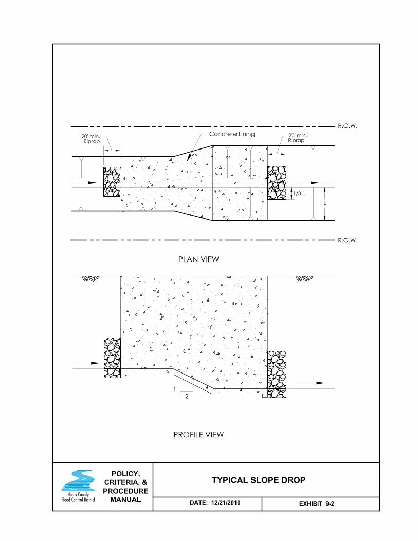


12/21/10 Update
Harris County Flood Control District Policy, Criteria, and Procedure Manual 10-1
SECTION 10 – EROSION AND SEDIMENT CONTROL
10.1 Introduction
Overview 10.1.1
Address erosion potential in all designs of open channels, detention basins, and hydraulic structures. Knowledge of the geotechnical conditions, channel hydraulics, and actual field conditions are essential in developing a good erosion control plan. However, due to the dynamic and complex nature of water flow and the soil interface, erosion control plans are usually based on empirical relationships, water flow fundamentals, and field experience.
Causes of Erosion 10.1.2
Erosion in a channel or detention basin is caused by:
1. Excessive water velocity or turbulence within the banks, especially at confluences, storm sewer outfalls, bends, drop structures, and transitions.
2. Sheet flow over the bank.
3. Water flow out of the banks. (Examples: Natural ground water or leaks from swimming pools, irrigation systems, waterlines, etc.)
Results of Erosion 10.1.3
Erosion results in one or more of the following:
Reduction of channel conveyance due to increased turbulence or flow irregularities.
Reduction of channel conveyance or stormwater storage due to sedimentation.
Interference with maintenance.
Bank failures that lead to safety problems or threat to adjacent property.
Geotechnical Investigation 10.1.4
Submit a geotechnical report that specifically addresses soil types (including dispersive soils), erosion potential, and suggested erosion control measures.
Follow the geotechnical investigation requirements as provided in HCFCD’s Geotechnical Investigation Guidelines in Appendix D.
Continued on next page

12/21/10 Update
Harris County Flood Control District Policy, Criteria, and Procedure Manual 10-2
10.1 Introduction, Continued
Specific Problem Areas 10.1.5
Criteria at specific potential problem areas are in the sections listed below.
Problem Area Section
Bends/Curves 5.8
Bridges 7
Culverts 8
Pipe Outfalls 11.3
Horizontal Transitions 5.7
Confluences 5.6
Transition Control Structures 9
12/21/10 Update
Harris County Flood Control District Policy, Criteria, and Procedure Manual 10-3
10.2 Hydraulic Considerations
Maximum Velocities 10.2.1
Maximum average cross-section velocities are based on a 1% exceedance probability flow. Values are presented in Section 4.4.1, Maximum Velocities.
Turbulence 10.2.2
Erosion often occurs in areas of high turbulence, such as at bridge bents, outfall pipes, drop structures, and abrupt transitions. Avoid creating high turbulence, if possible. Where it cannot be avoided, provide adequate erosion and scour protection.

12/21/10 Update
Harris County Flood Control District Policy, Criteria, and Procedure Manual 10-4
10.3 Turf Establishment
Introduction 10.3.1
An established permanent turf grass stand is an effective and economical method to stabilize banks and minimize erosion caused by overbank flow and high velocities in channels and detention basins. Establishing a good turf grass cover requires preparing the seedbed, fertilizing, selecting the proper seed, seeding properly, keeping the seed in place, and watering.
Turf Grass Establishment Criteria 10.3.2
Turf grass establishment is required on all areas within HCFCD maintained facilities disturbed by construction, except channel bottoms and where structural erosion control measures are used.
Criteria for turf grass established by the developer or public entity is as follows:
Establish turf grass as quickly as possible to minimize erosion and sedimentation.
The means for establishing turf grass are in HCFCD Standard Specification Section 02921 - Turf Establishment.
Turf grass establishment is required for final acceptance at the end of the one year warranty period. Minimum acceptance criteria is:
– 75% coverage of live Bermuda grass on disturbed areas.
– No erosion or rills deeper than 4”.
Conditions for HCFCD to Perform Turf Grass Establishment 10.3.3
HCFCD will perform turf grass establishment for a public entity or developer who disturbs existing or proposed HCFCD right-of-way if all conditions below are satisfied:
1. Follow applicable procedures in this manual for the proposed work.
2. The Turf Establishment Agreement is executed and the fee paid prior to commencing construction.
3. The owner or contractor notifies HCFCD 14 calendar days prior to completion of the work or a portion of the work to allow time for HCFCD to schedule the turf grass contractor.

12/21/10 Update
Harris County Flood Control District Policy, Criteria, and Procedure Manual 10-5
10.4 Concrete Lining
Overview 10.4.1
Concrete lining is poured in place and reinforced concrete is used for erosion protection in channels or detention basins.
Basis of Design 10.4.2
The stability of concrete lining is based on its ability to withstand temperature changes, shear forces created by flow in the channel, and the hydrostatic forces from the soil. Important factors include:
Concrete thickness and reinforcing
Transitions
Soil type
Flow velocity
Channel geometry
Channel grade
Concrete Lining Criteria 10.4.3
Criteria are presented in the table below. See Appendix D, HCFCD Standard Concrete Channel Lining Detail Sheet, for a typical section and plan view.
Feature Criteria
Side slopes no steeper than 2(H):1(V)
Upper limit of lining 1/3 up side slope minimum
Concrete thickness on slope and bottom
5 inches minimum
Minimum reinforcing steel #4 bars on 12 inch centers each way or 6"x6"xW4.5xW10 welded wire fabric
Minimum toe wall depth Channel bottom – 3 feet
Side slope – 2 feet
Top of lining – 2 feet
Toe wall thickness 8 inches
Top of lining See HCFCD Standard Concrete Lining Detail Sheet in Appendix D
Continued on next page

12/21/10 Update
Harris County Flood Control District Policy, Criteria, and Procedure Manual 10-6
10.4 Concrete Lining, Continued
Concrete Lining Criteria Continued 10.4.3
Geotechnical investigations are required to confirm side slopes. Channel linings do not provide structural support for the soil.
Partially concrete-lined channels require backslope drainage systems.
Concrete toe walls are required on all sides to reduce the chance of flow under the lining and decrease the chance of lining failure.
Riprap is required in channels a minimum of 20 feet upstream and downstream of the paving across the bottom and one-third up the side slopes to decrease flow velocities.
Access stairways are required for side slopes 2.5:1 and steeper. Locate stairways on the upstream side of road crossings and at intervals less than 1500 feet.
Detailed construction drawings are required where removing, modifying, or replacing existing concrete lining is proposed for a project. Example: Installing a new storm sewer outfall through concrete lining.

12/21/10 Update
Harris County Flood Control District Policy, Criteria, and Procedure Manual 10-7
10.5 Riprap
Overview 10.5.1
Riprap is broken concrete rubble or stone used for erosion or scour protection in channels or detention basins.
Proper gradation and placement is essential to the success of riprap.
Basis of Design 10.5.2
The stability of riprap is based on the ability of the riprap to withstand the shear forces created by flow in the channel. Important factors include:
Stone size and shape.
Stone weight and gradation.
Riprap mat thickness.
Bedding.
Flow velocity.
Channel geometry.
Channel grade.
Riprap Criteria 10.5.3
Criteria are presented in the table below. See HCFCD Standard Storm Sewer Outfall and Riprap Detail Sheet in Appendix D for a typical section and plan view.
Feature Criteria
Side slopes no steeper than 2(H):1(V)
Upper limit of riprap 1/3 up side slope minimum
Minimum riprap mat thickness
18 inches
Side slope finish Finish leveling with topsoil and no riprap visible on surface
Minimum limit into channel or detention bottom
1.5 times the mat thickness from toe of slope
Minimum toe wall depth at toe of slope and in bottom
1.5 times the mat thickness
Continued on next page

12/21/10 Update
Harris County Flood Control District Policy, Criteria, and Procedure Manual 10-8
10.5 Riprap, Continued
Riprap Criteria Continued 10.5.3
Use HCFCD standard riprap sizes, gradations, and mat thickness in HCFCD Standard Specification Section 02378 – Riprap and Granular Fill, where applicable.
See Appendix D, HCFCD Standard Storm Sewer Outfall and Riprap Detail Sheet.
Geotechnical investigations are required to confirm side slopes.
Riprap-lined channels require backslope drainage systems.
For minimum riprap extent at pipe outfalls, drop structures, bends, etc., see the sections in this manual for those specific features.
Detailed construction drawings are required where removing, modifying, or replacing existing riprap is proposed for a project. Example: Installing a new storm sewer outfall through riprap.

12/21/10 Update
Harris County Flood Control District Policy, Criteria, and Procedure Manual 10-9
10.6 Other Linings
Overview 10.6.1
If other erosion protection linings are being considered, consult with HCFCD prior to design for minimum criteria, if available.
Detailed construction drawings are required where removing, modifying, or replacing existing linings is proposed for a project. (Example: Installing a new storm sewer outfall through articulated concrete blocks.)

12/21/10 Update
Harris County Flood Control District Policy, Criteria, and Procedure Manual 10-10
10.7 Sediment Control During Construction
Criteria 10.7.1
Comply with the Texas Pollutant Discharge Elimination System (TPDES) requirements for Harris County.
12/21/10 Update
Harris County Flood Control District Policy, Criteria, and Procedure Manual 11-1
SECTION 11 – BACKSLOPE DRAINAGE SYSTEMS
AND PIPE OUTFALLS
11.1 Backslope Drainage Systems
Introduction 11.1.1
Backslope drainage systems collect stormwater within the maintenance berm and convey it to the channel or detention basin through a pipe to minimize overbank flow and erosion. Backslope drainage systems are necessary for the long-term integrity of grass-lined channels or detention basins.
Where to Use 11.1.2
Backslope drainage systems are required for HCFCD maintained channels and detention basins except where:
The side slope is concrete-lined to the top of bank.
The depth at the toe of the side slope is less than 7 feet.
The ground slopes 2% or steeper away from the top of bank to an adjacent curb and gutter street or roadside ditch.
The ground slopes 2% or steeper from the top of bank to an adjacent jurisdictional wetland that will remain.
Continued on next page

12/21/10 Update
Harris County Flood Control District Policy, Criteria, and Procedure Manual 11-2
11.1 Backslope Drainage Systems, Continued
Criteria 11.1.3
Criteria for backslope swale design are in the table below.
Feature Criteria
Depth from natural ground at edge of right-of-way
0.5 foot minimum
Depth from top of channel or detention basin bank
1 foot minimum
Depth of swale 2 feet maximum
Depth of swale at summit 0.5 foot
Depth at interceptor structure centerline
2.5 feet maximum
Swale side slope No steeper than 1.5(H):1(V)
Swale gradient, typical 0.2%
Swale gradient, dispersive clays 0.4%
Swale centerline 5.5 feet inside right-of-way line
Interceptor structure spacing, typical
800 feet maximum (400 feet from swale summit)
Interceptor structure spacing, dispersive clays
400 feet maximum (200 feet from swale summit)
Berm width for the backslope drainage system
10 feet minimum
Note: Establish final interceptor structure elevations and locations based on actual or proposed ground topography and local drainage patterns.
Continued on next page
12/21/10 Update
Harris County Flood Control District Policy, Criteria, and Procedure Manual 11-3
11.1 Backslope Drainage Systems, Continued
Criteria, Continued 11.1.3
Design and construct interceptor structures in accordance with HCFCD Standard Interceptor Structure Detail Sheet in Appendix D.
Include design details of interceptor structures for pipe sizes larger than the ones shown on the HCFCD Standard Interceptor Structure Detail Sheet in Appendix D.
Developed property is not allowed to drain to backslope swales, except as noted below:
- To avoid retaining walls and steep earthen slopes at the back of residential lots that adjoin a HCFCD maintained facility, one-half or less of adjacent residential lots may be sloped to drain to a backslope drainage system.
- Earthen slopes over 6 inches high and steeper than 3(H):1(V) are not allowed adjacent to a backslope swale.
- Where undeveloped acreage drains into the backslope swale system, no more than 10 acres (15 cfs) can drain into one standard backslope interceptor structure. If necessary, include additional interceptor structures and/or larger pipes than the 24 inch minimum to carry the total offsite flow (submit a drainage area map). Other interceptor structures are available to collect offsite flow as shown on the HCFCD Standard Interceptor Structure Detail Sheet in Appendix D.
- Urban interceptor structures can be used in developed areas with limited right-of-way if HCFCD approval is obtained prior to submitting construction drawings.
Do not place interceptor structures in the corners of a detention basin or in channel curves tighter than 45 degrees.
Locate high points of backslope swales in the corners of a detention basin and in channel curves, so storm water drains away from the corners and curves.
12/21/10 Update
Harris County Flood Control District Policy, Criteria, and Procedure Manual 11-4
11.2 Offsite Ditch Interceptor Structure
Introduction 11.2.1
The offsite ditch interceptor structure is used to convey flow from small ditches into HCFCD maintained facilities through a pipe to minimize overbank flow and erosion problems. The ditch can be along a roadway or a natural or manmade ditch draining to the HCFCD facility from adjacent property.
Criteria 11.2.2
Design and construct offsite interceptor structures in accordance with HCFCD Standard Interceptor Structure Detail Sheet in Appendix D.
Confirm pipe sizes by submitting a drainage area map and calculations using the Harris County method for determining flow rates for storm sewers or the bankfull capacity of the ditch.
Locate offsite ditch interceptor structures just outside HCFCD right-of-way, wherever possible. If not, locate it as close to the edge of the right-of-way as possible to maximize the room for maintenance and construction vehicles. Minimum space from top of bank to edge of offsite ditch interceptor structure is 20 feet.

12/21/10 Update
Harris County Flood Control District Policy, Criteria, and Procedure Manual 11-5
11.3 Pipe Outfalls
Introduction 11.3.1
Pipe and box outfalls are a common method for conveying flow into channels and detention basins.
Note: References to pipe outfalls include box outfalls, as well.
Considerations 11.3.2
Factors to consider when designing and laying out a pipe outfall into a HCFCD maintained facility are:
Exit velocity from the pipe.
Alignment relative to the flow in the HCFCD facility.
Location of the pipe relative to the HCFCD facility geometry.
Location of the pipe relative to other structures in the HCFCD facility.
Backflow Preventers 11.3.3
Backflow preventers, such as flap gates, on storm sewer outfalls are not accepted by HCFCD for maintenance since they are part of the storm sewer system. They are permissible if another entity agrees to maintain them, provided the criteria is satisfied in Section 6.7.8, Backflow Preventers,
HCFCD will maintain backflow preventers on pipe or box structures draining from a HCFCD detention facility into a HCFCD channel (see Section 6.7.8, Backflow Preventers).

12/21/10 Update
Harris County Flood Control District Policy, Criteria, and Procedure Manual 11-6
11.3 Pipe Outfalls, Continued
Design Criteria 11.3.4
Standard Details:
Design and construct outfall pipes in grass-lined channels or detention basins in accordance with HCFCD Standard Storm Sewer Outfall and Riprap Detail Sheet in Appendix D.
Design and construct outfall pipes in concrete-lined channels or detention basins in accordance with HCFCD Standard Concrete Channel Lining Detail Sheet in Appendix D.
Use the pipe adjustment details shown on the HCFCD Standard Storm Sewer Outfall and Riprap Detail Sheet in Appendix D, where applicable, and include custom pipe adjustment details where necessary.
Install riprap erosion protection in grass-lined channels for pipes 48 inches and larger, wastewater treatment plant outfall pipes, and where the design velocity out of the pipe exceeds the maximum for the soil type in Section 4.4.1, Maximum Velocities table. Minimum riprap layout is shown on the HCFCD Standard Storm Sewer Outfall and Riprap Detail Sheet in Appendix D.
Use corrugated metal pipe (galvanized steel or aluminum) or HDPE pipe with a minimum 24-inch diameter for outfall pipes within a HCFCD facility right-of-way.
Plan Layout:
Place a standard manhole or junction box just outside the ultimate channel or detention basin right-of-way.
Place all storm sewer inlets outside HCFCD facility right-of-way.
Angle pipes and boxes downstream a minimum of 30 degrees starting at the last manhole and measured from line perpendicular to the channel.
Locate storm sewer outfalls 48 inches and larger on the downstream side of bridges and culverts.
Continued on next page

12/21/10 Update
Harris County Flood Control District Policy, Criteria, and Procedure Manual 11-7
11.3 Pipe Outfalls, Continued
Design Criteria, continued 11.3.4
Exceptions:
Pave the corrugated metal pipe invert of wastewater effluent outfalls with concrete or use plastic pipe designed for wastewater effluent.
For submerged inflow pipes or boxes, see Section 11.3.5, Submerged Pipes below.
HDPE pipes are not allowed to outfall through concrete slope paving or concrete headwalls.
Inflow pipes from backslope drains into detention basins can match the dry bottom elevation.
Storm sewer inflow pipe invert into detention basins can match the pilot channel flowline.
Storm sewer inflow pipes into detention basins can be reinforced concrete pipe (see Section 6.6.2, Inflow Structures).
Where concrete pipe or box culverts are used to convey inflow into a grass-lined detention basin or channel, provide a structurally designed headwall recessed into the detention basin or channel slope at the end of the pipe. Concrete slope paving alone is not allowed.
Submerged Inflow Pipes 11.3.5
Storm sewer pipes or boxes carrying inflow into a HCFCD maintained stormwater detention basin may be partially or fully submerged in a deep or shallow pool provided:
Current Harris County regulations or the criteria of the entity who will maintain the inflow pipes or boxes are followed.
The construction drawings designate the entity responsible for maintenance and repair of the submerged pipe within the HCFCD detention basin.
A complete detail is included in the construction drawings.
Partially or fully submerged pipes are RCP. No CMP or HDPE is allowed.
A structurally designed concrete headwall or anchoring system is used at the end of the pipe.
Note: Do not submerge backslope drain pipes.


12/21/10 Update
Harris County Flood Control District Policy, Criteria, and Procedures Manual 12-1
SECTION 12 – CHANNEL ENCLOSURES
12.1 Introduction
Overview 12.1.1
Channels normally maintained by HCFCD can be enclosed provided the criteria and procedures in this manual are followed.
Analysis and Methodologies 12.1.2
Hydraulic analysis and submittal requirements that apply to channels also apply to channel enclosures. Hydraulic aspects specific to channel enclosures are presented in this section.
Maintenance Responsibility 12.1.3
Since the HCFCD’s primary responsibility is for open drainage facilities, convey the right-of-way and maintenance responsibility of an enclosed channel to a taxing entity that maintains underground drainage systems.

12/21/10 Update
Harris County Flood Control District Policy, Criteria, and Procedures Manual 12-2
12.2 Design Criteria
Application 12.2.1
The criteria in this section apply where the drainage area for the enclosure is greater than 200 acres or where the HCFCD maintained facility would normally begin.
Hydraulic Criteria 12.2.2
Hydraulic criteria are:
For new developments or new drainage facilities, design the pipe or box to contain the 1% exceedance probability, 24-hour storm event within the facility right-of-way for ultimate watershed conditions. Accommodate the energy grade line within the facility right-of-way, as well.
Verify internal, entrance, and exit velocities are not excessive (see Section 4.4.1, Maximum Velocities).
Show how the 1% exceedance probability flow will get into the pipe or box.
Accommodate extreme event flows (in excess of the 1% exceedance probability) where possible.
Submit hydraulic calculations, profiles, and design for review.
Structural Criteria 12.2.3
Use the criteria from the jurisdiction that is going to maintain the enclosed drainage facility.
Manholes and Inlets 12.2.4
Criteria for manholes are:
Use the criteria from the jurisdiction that is going to maintain the enclosed drainage facility.
Manholes can be combined with City of Houston Type "E" or Type "B" inlets to drain surface swales.
Select inlets to minimize reduction in flow capacity due to clogging.
Right-of-Way 12.2.5
The right-of-way width for an enclosed channel shall be the outside width of the pipe(s) or box(es) plus a distance on each side equal to the flowline depth measured from natural ground or proposed fill elevation, whichever is higher and rounded up to the nearest 5 feet. The minimum width on each side shall be 10 feet.
Encompass all manholes within the right-of-way for the facility. Extend the right-of-way limit 5 feet from the edge of the manholes and inlets.

12/21/10 Update
Harris County Flood Control District Policy, Criteria, and Procedures Manual 13-1
SECTION 13 –EXTREME EVENT OVERFLOW
13.1 Introduction
Overview 13.1.1
Stormwater runoff that travels on the surface trying to reach an open channel or detention basin is referred to, in this manual, as overland flow. Local jurisdictions, such as Harris County and the City of Houston, have regulations and requirements for accommodating extreme event overland flow within their streets and storm sewers.
This section covers the criteria for conveying extreme event overland flow into HCFCD maintained channels or detention basins.
For swales or ditches carrying normal flows to a HCFCD maintained facility, see Section 11, Backslope Drainage Systems and Pipe Outfalls.

12/21/10 Update
Harris County Flood Control District Policy, Criteria, and Procedures Manual 13-2
13.2 Extreme Event Overland Flow Swales
Criteria 13.2.1 A typical extreme event overland flow swale section within a HCFCD right-
of-way is presented in Exhibit 13-1 for articulated concrete block and in Exhibit 13-2 for concrete lining.
Criteria are:
Size the swale to carry the overflow appropriate for the situation or as required by the jurisdictional entity.
Set the high bank elevation in the swale below the nearest and lowest slab elevation.
Design the swale geometry such that inspection and maintenance vehicles in the maintenance berm can drive across the swale during dry periods.
Criteria are:
– 6 foot minimum bottom width.
– 4 foot maximum depth.
– Side slopes 5(H):1(V) or flatter.
Line swales across the maintenance berm with concrete or articulated concrete blocks using the criteria in Section 10, Erosion and Sediment Control.
Do not drain backslope swales into the extreme event overflow system.
At the extreme event swale outfall, use concrete lining or articulated concrete blocks on the channel or detention basin side slope, and into the bottom at least 5 feet.
Considerations 13.2.2
For articulated concrete blocks, consider establishing turf grass by adding topsoil to fill the voids and at least one inch on the top of the blocks to allow for settling.
Modify design to accommodate onsite soil conditions such as dispersive clays.

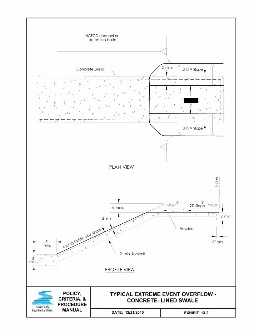

12/21/10 Update
Harris County Flood Control District Policy, Criteria, and Procedure Manual 14-1
SECTION 14 – PIPELINES, UTILITIES, AND ROADWAYS
14.1 Introduction
Overview 14.1.1
Pipelines, utilities, and roadways are allowed to cross HCFCD facilities, and roadway drainage systems are allowed to outfall into HCFCD facilities provided the criteria and procedures in this manual are followed, and the utility, pipeline, or roadway owner agrees to the conditions.
HCFCD does not maintain or operate pipelines, utilities, or roadways.
Review and Coordination 14.1.2
Follow the review and coordination process in Section 2.9, Non-Flood Control Features, for pipelines, utilities, and roadways proposed to be placed in, on, over, or under a HCFCD maintained facility.
Early coordination with HCFCD is recommended; particularly obtaining concurrence on the location within the HCFCD facility.
Criteria 14.1.3
HCFCD acceptance criteria for placing a pipeline, utility, or roadway within a HCFCD maintained facility are presented in Section 2.2.7, Non-Flood Control Features Accepted in a HCFCD Facility. Specific criteria and conditions are in this section.
Easements 14.1.4
The procedure for acquiring an easement within a HCFCD fee strip or easement is in Section 15.4, Easements for Pipelines, Utilities, and Roadways.

12/21/10 Update
Harris County Flood Control District Policy, Criteria, and Procedure Manual 14-2
14.2 Crossings
Criteria and Conditions 14.2.1
Specific criteria and conditions for crossings within HCFCD maintained facilities are:
General:
Submit location of proposed crossing for HCFCD approval prior to preparing construction drawings.
Submit hydraulic analysis to show no adverse impact to the HCFCD facility or flood levels, if the crossing is overhead or exposed in the channel or detention basin. If a pipeline or utility line is six inches in diameter or less and all other criteria are followed, no hydraulic analysis is required.
An easement for the pipeline, utility, or roadway across HCFCD right-of-way is required from the underlying fee owner.
Easement widths must encompass the pipeline, utility, or roadway plus the area disturbed by construction, repair, or rehabilitation.
Design:
Locate pipes or conduits spanning the channel 1.5 feet or more above the existing or ultimate 1% exceedance water surface, whichever is higher and if possible, without causing an impact on the existing or ultimate 1% exceedance water surface profile (see Exhibit 14-1).
Minimum cover over pipelines or buried utilities is 5 feet below the ultimate channel section (see Exhibit 14-1).
Design to minimize impact on the HCFCD facility maintenance and access.
Manholes are not allowed in HCFCD right-of-way.
Continued on next page

12/21/10 Update
Harris County Flood Control District Policy, Criteria, and Procedure Manual 14-3
14.2 Crossings, Continued
Criteria and Conditions, continued 14.2.1
Construction related items:
Maintain or reestablish existing backslope drainage systems.
Haul off all trench excavation not used for backfill from HCFCD right-of-way and outside 1% exceedance (100-year) floodplain.
Backfill within the channel or detention right-of-way shall be in accordance with the backfill requirements specified by the respective city, county, utility company, or the applicable HCFCD standard specification, whichever is more restrictive.
Remove abandoned lines within HCFCD right-of-way.
Repair all damage to the HCFCD facility.
Reestablish vegetation disturbed in the HCFCD or drainage right-of-way. This may include a maintenance period to restore to the condition prior to disturbance. Vegetation includes turf, trees, and shrubs.

12/21/10 Update
Harris County Flood Control District Policy, Criteria, and Procedure Manual 14-4
14.3 Parallel Pipelines and Utilities in HCFCD Facilities
Overview 14.3.1
Pipelines and utilities within HCFCD facilities and parallel to the channel or detention basin are not allowed.


12/21/10 Update
Harris County Flood Control District Policy, Criteria, and Procedure Manual 15-1
SECTION 15 - RIGHT-OF-WAY
15.1 Introduction
Overview 15.1.1
Establishing adequate right-of-way for HCFCD maintained facilities is essential for construction, expansion, and long-term operation, maintenance, and rehabilitation. In addition, easements for pipelines, utilities, and roadways across a HCFCD maintained facility are also necessary for those facilities.
Definitions 15.1.2
RIGHT-OF-WAY – An interest in real property, either in fee or easement.
HCFCD RIGHT-OF-WAY – Implies HCFCD has property rights to manage the HCFCD facility (see Section 1.1.5, Definitions).
ULTIMATE RIGHT-OF-WAY – The maximum right-of-way necessary to construct and maintain a channel or detention facility, assuming full upstream development, under stormwater management policies in effect for that watershed.
FEE, FEE SIMPLE, FEE TITLE – Full ownership of real property by an individual or entity.
EASEMENT – A limited interest in real property for a specific purpose, usually designated in the granting instrument or plat. Another entity or individual has fee title to the property.
DEDICATION – The act of a property owner who sets aside a portion of his property for the use of the public for a specific purpose. A dedication may be accomplished by plat or separate instrument and creates an easement.
CONVEYANCE – Transfer of a real property interest, either in fee or easement, from one party to another.
Continued on next page

12/21/10 Update
Harris County Flood Control District Policy, Criteria, and Procedure Manual 15-2
15.1 Introduction, Continued
Real Estate Interest Options 15.1.3
HCFCD preferences and real estate interest options available are shown in the table below.
Real Estate Interest HCFCD Preference
HCFCD Fee Main stems and regional facilities.
HCFCD or Public Easement
Tributaries and detention basins with no multi-use features.
Public Easement Tributaries and detention basins with multi-use features.
Examples of multi-use features include parks, trails, trees, and water quality features.
Where other entities help maintain the HCFCD facility with financial assistance from the HCFCD, a HCFCD easement or fee strip is required.

12/21/10 Update
Harris County Flood Control District Policy, Criteria, and Procedure Manual 15-3
15.2 Right-of-Way Determination
Existing Rights-of-Way 15.2.1
Determine existing rights-of-way and associated property rights for the HCFCD facility when a modification is proposed to an existing HCFCD maintained facility, or a development is proposed adjacent to an existing HCFCD maintained facility.
Channels 15.2.2
Guidelines for determining proposed channel rights-of-way are in Section 5.5, Right-of-Way.
Detention Basins 15.2.3
Guidelines for determining proposed detention basin rights-of-way are in Section 6.5, Right-of-Way.
Channel Enclosures 15.2.4
Guidelines for determining proposed rights-of-way for channel enclosures are in Section 12.2.5, Right-of-Way.

12/21/10 Update
Harris County Flood Control District Policy, Criteria, and Procedure Manual 15-4
15.3 Right-of-Way Conveyance and Dedication
Introduction 15.3.1
Fee strips and easements are conveyed to HCFCD by separate instrument. Public drainage easements are dedicated by subdivision plat or separate instrument. Procedures for conveyance and dedication are presented below.
Separate Instrument Conveyance or Dedication 15.3.2
The process for conveying a fee strip or easement to HCFCD or dedicating a public easement by separate instrument is presented in the table below.
Step Description 1 Applicant verifies proposed right-of-way width or area with the
HCFCD Watershed Coordination Department or Property Management Department.
2 Applicant provides: Deed for parent tract establishing current ownership. Three (3) copies of the metes and bounds description on
8-1/2” x 11” white paper. Three (3) copies of the tract plat on 8-1/2” x 11” white
paper. Environmental site assessment report for fee conveyances.
Submittal requirements: Must conform to HCFCD survey guidelines. All copies must be sealed and signed by a Texas Registered
Professional Land Surveyor. Tract(s) must be monumented.
3 HCFCD Property Management Department reviews metes and bounds description and tract plat for compliance. (Returns to applicant for corrections, if necessary.)
4 HCFCD Property Management Department provides standard language instrument to applicant.
5 Applicant drafts conveyance or dedication instrument and submits to the HCFCD Property Management Department for review.
6 HCFCD Property Management Department forwards the instrument to the applicant for execution.
7 Applicant makes any corrections necessary and returns executed instrument to HCFCD Property Management Department.
8 HCFCD Property Management Department confirms instrument is properly executed, submits to the Harris County Attorney for review, forwards to Commissioners Court for acceptance, and then records instrument.
Continued on next page
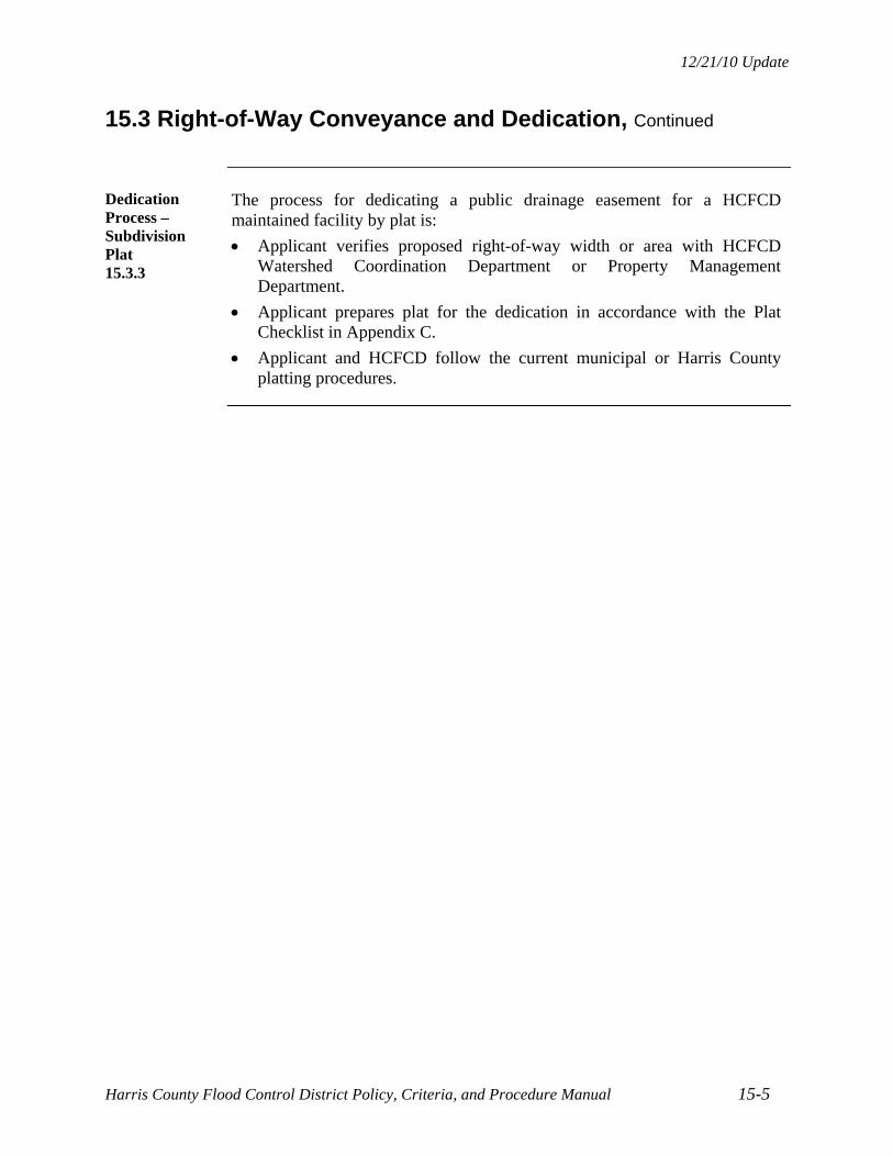
12/21/10 Update
Harris County Flood Control District Policy, Criteria, and Procedure Manual 15-5
15.3 Right-of-Way Conveyance and Dedication, Continued
Dedication Process – Subdivision Plat 15.3.3
The process for dedicating a public drainage easement for a HCFCD maintained facility by plat is:
Applicant verifies proposed right-of-way width or area with HCFCD Watershed Coordination Department or Property Management Department.
Applicant prepares plat for the dedication in accordance with the Plat Checklist in Appendix C.
Applicant and HCFCD follow the current municipal or Harris County platting procedures.
12/21/10 Update
Harris County Flood Control District Policy, Criteria, and Procedure Manual 15-6
15.4 Easements for Pipelines, Utilities, and Roadways
Requirement 15.4.1
Encompass new pipelines, utilities, and roadways located within a HCFCD maintained facility in an easement to facilitate inspection, maintenance, and rehabilitation of the feature.
Procedures 15.4.2
Procedures for coordinating pipelines, utilities, and roadways with HCFCD and establishing easement widths are presented in Section 14, Pipelines, Utilities, and Roadways.
Easements in New Subdivisions 15.4.3
For new subdivisions or developments established by platting, dedicate the easements for utilities and roadways located within a HCFCD maintained facility by the plat.
Right to Cross Paragraph 15.4.4
When a right-of-way is conveyed to HCFCD in fee, a right to cross paragraph can be included in the instrument to allow future crossings without having to obtain individual easements, but subject to HCFCD review and approval.
Obtaining an Easement from Underlying Fee Owner 15.4.5
If the right-of-way for an existing HCFCD maintained facility is a HCFCD easement or public drainage easement, then the owner of the pipeline, utility, or roadway must obtain an easement from the underlying fee owner.
Prior to signing the construction drawings, a copy of the easement instrument is required.
Continued on next page
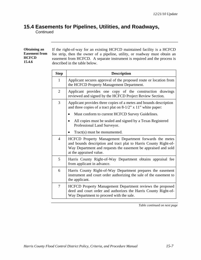
12/21/10 Update
Harris County Flood Control District Policy, Criteria, and Procedure Manual 15-7
15.4 Easements for Pipelines, Utilities, and Roadways, Continued
Obtaining an Easement from HCFCD 15.4.6
If the right-of-way for an existing HCFCD maintained facility is a HCFCD fee strip, then the owner of a pipeline, utility, or roadway must obtain an easement from HCFCD. A separate instrument is required and the process is described in the table below.
Step Description
1 Applicant secures approval of the proposed route or location from the HCFCD Property Management Department.
2 Applicant provides one copy of the construction drawings reviewed and signed by the HCFCD Project Review Section.
3 Applicant provides three copies of a metes and bounds description and three copies of a tract plat on 8-1/2” x 11” white paper:
Must conform to current HCFCD Survey Guidelines.
All copies must be sealed and signed by a Texas Registered Professional Land Surveyor.
Tract(s) must be monumented.
4 HCFCD Property Management Department forwards the metes and bounds description and tract plat to Harris County Right-of-Way Department and requests the easement be appraised and sold at the appraised value.
5 Harris County Right-of-Way Department obtains appraisal fee from applicant in advance.
6 Harris County Right-of-Way Department prepares the easement instrument and court order authorizing the sale of the easement to the applicant.
7 HCFCD Property Management Department reviews the proposed deed and court order and authorizes the Harris County Right-of-Way Department to proceed with the sale.
Table continued on next page

12/21/10 Update
Harris County Flood Control District Policy, Criteria, and Procedure Manual 15-8
15.4 Easements for Pipelines, Utilities, and Roadways, Continued
Obtaining an Easement from HCFCD, Continued 15.4.6
Table, continued
Step Description
8 Commissioners Court approves the sale of the easement.
9 Harris County Right-of-Way Department concludes the transaction:
1. Collects the payment for the easement.
2. Records the easement instrument.
3. Returns the original instrument to the applicant.
4. Sends copy of instrument to the HCFCD Property Management Department.
12/21/10 Update
Harris County Flood Control District Policy, Criteria, and Procedure Manual 16-1
SECTION 16 – WATER QUALITY FEATURES
16.1 Introduction
Overview 16.1.1
Improving water quality in creeks, bayous, and channels in Harris County is a goal of the community and a requirement of the Texas Pollutant Discharge Elimination System (TPDES) permit issued by the Texas Commission on Environmental Quality (TCEQ) to Harris County, the City of Houston, HCFCD, and TxDOT (collectively called the Joint Task Force (JTF)). The permit and corresponding City of Houston ordinance and Harris County regulation requires industrial activities, construction sites, new development, and significant redevelopment to implement and maintain structural and nonstructural controls to reduce pollutants in stormwater run-off.
Review and Coordination Process 16.1.2
For water quality features placed in a HCFCD maintained facility to comply with the TPDES permit, use the review and coordination process presented in Section 2.9, Non-Flood Control Features.
Water Quality Feature Maintenance 16.1.3
HCFCD will maintain only the floatable collection screen water quality feature in a HCFCD maintained detention basin.
For all other water quality features in a HCFCD maintained detention basin, a sponsor is required to maintain the water quality feature and comply with the conditions in Section 2.2.7, Non-Flood Control Features Allowed in a HCFCD Facility.

12/21/10 Update
Harris County Flood Control District Policy, Criteria, and Procedure Manual 16-2
16.2 Acceptance Criteria
Acceptance Criteria in a HCFCD Maintained Detention Basin 16.2.1
HCFCD will allow a water quality feature in a detention basin provided:
The water quality feature is constructed within a proposed or existing HCFCD maintained detention basin.
The water quality feature and operation does not unduly interfere with the function, operation, maintenance, or rehabilitation of the HCFCD detention basin, or other multi-purpose uses, such as environmental, recreation, or aesthetic features.
The water quality feature is approved by the jurisdiction responsible for the water quality function of the feature.
The appropriate vegetation establishment criteria are satisfied (see Section 10.3, Turf Establishment).
For new or modified detention basins, the acceptance criteria in Section 2.2.3, Acceptance for HCFCD Maintenance is satisfied.
The water quality feature satisfies the criteria in Section 2.2.7, Non-Flood Control Features Allowed in a HCFCD Facility.

12/21/10 Update
Harris County Flood Control District Policy, Criteria, and Procedure Manual 16-3
16.3 Design Criteria
Introduction 16.3.1
Design criteria related to the water quality feature in a HCFCD maintained detention basin are based on access and maintenance.
As methods and techniques for complying with the TPDES permit and TMDL requirements change, the HCFCD design criteria will be updated.
Floatable Collection Screen 16.3.2
For floatables collection screens:
Use the Exhibit 16-1 as a guide for design at specific locations.
All other HCFCD design criteria are in effect.
Provide an all weather access road on the maintenance berm to properly access the collection screen to facilitate debris removal even in wet conditions (see Section 16.3.4, All Weather Access Road).
Vertical collection screens are not acceptable.
Locate the floatables collection screen and associated concrete paving in a compatible location in the basin.
Continued on next page

12/21/10 Update
Harris County Flood Control District Policy, Criteria, and Procedure Manual 16-4
16.3 Design Criteria, Continued
Wet Bottom Storm Water Quality Features 16.3.3
For wet bottom features in HCFCD detention basins that are required for storm water quality and require periodic silt removal:
Coordinate the design with the HCFCD Environmental Services Division.
Include an all weather access road (Section 16.3.4) and pad where silt removal is to occur (can be combined with the turnaround). Coordinate design with the HCFCD.
Include permanent markers indicating when sediment removal is needed and the limits of removal, if required.
All Weather Access Road 16.3.4
For all weather access roads in HCFCD facilities:
Construct out of reinforced concrete road paving or crushed limestone with subgrade.
For a crushed limestone access road:
- Include a minimum 8” subgrade of 3” x 5” granular fill or cement stabilized sand.
- Use a minimum 6” crushed limestone riding surface.
For a reinforced concrete paved road, use Harris County criteria for residential roads.
Use a minimum 2% cross slope for drainage.
Width at least 15 feet.
When accessing the bottom of a detention basin, use a grade no steeper than 7% (14:1).
Include a turnaround (circular with minimum radius of 50 feet) or that allows one-way through truck traffic.


12/21/10 Update
Harris County Flood Control District Policy, Criteria, and Procedure Manual 17-1
SECTION 17 – ENVIRONMENTAL AND
CULTURAL RESOURCES COMPLIANCE
17.1 Environmental Compliance
Overview 17.1.1
Compliance with appropriate federal, state, and local environmental rules, laws, regulations, and permits is required when working in or modifying HCFCD maintained facilities.
Common environmental permits are the:
U.S. Army Corps of Engineers Section 404 and Section 10 permits.
State of Texas Section 401 Water Quality Certification.
Texas Commission on Environmental Quality (TCEQ) and Texas Pollutant Discharge Elimination System (TPDES) permit for construction and new development.
Other possible environmental or cultural permits are the:
EPA Comprehensive Environmental Response, Compensation, and Liability Act (CERCLA) related permits.
EPA Resource Conservation and Recovery Act (RCRA) related permits.
U.S. Fish and Wildlife Service Threatened and Endangered Species Act permit.
Texas Historical Commission Antiquities permit.
Existing HCFCD Maintained Facilities 17.1.2
When modifying existing HCFCD maintained facilities:
Coordinate proposed changes to the facility and features with the HCFCD Property Management Department.
Determine if existing features in the HCFCD facility were part of previous permit conditions.
Prepare and obtain new or revised permits, where applicable.
New HCFCD Facilities 17.1.3
For new HCFCD facilities, comply with applicable federal, state, and local environmental rules, laws, regulations, and permits. Obtain permits, where applicable.
Continued on next page

12/21/10 Update
Harris County Flood Control District Policy, Criteria, and Procedure Manual 17-2
17.1 Environmental Compliance, Continued
Review and Coordination Process 17.1.4
Use the review and coordination process in Section 2.8, New or Modified HCFCD Facilities, which includes the following for environmental compliance within existing or proposed HCFCD right-of-way:
Identification of environmental issues and permits in the preliminary design report.
Prior to construction, submit one copy of all applicable permits obtained for the project, or indicate on the Express Review Sheet the nationwide permit(s) that applies or that no permit is required for the project. Provide reports and correspondence associated with the permit, if requested.
Following construction, written certification that the work was performed in conformance with the permits, if applicable.
Provide documentation from the Corps of Engineers, Galveston District, that mitigation is complete, if applicable.
Water Quality Features 17.1.5
If a water quality feature is required to comply with the TPDES permit, HCFCD will accept only floatable collection screens for maintenance in a HCFCD maintained detention basin (not channel) provided the criteria in Section 16, Water Quality Features, are satisfied.
Mitigation 17.1.6
If mitigation such as a constructed wetland or tree and shrub planting is required for a Section 10 or Section 404 permit or 401 Water Quality Certification, the mitigation can be placed in a HCFCD maintained facility provided:
All acceptance criteria in Section 2.2.7, Non-Flood Control Features Accepted in a HCFCD Facility, are satisfied.
The sponsor of the mitigation feature agrees to be responsible for the construction, repair, rehabilitation, maintenance, and replacement of the mitigation feature.
The mitigation feature is physically delineated in the field to clearly distinguish areas of responsibility for maintenance, repair, rehabilitation, and replacement.
All applicable procedures in this manual are followed.

12/21/10 Update
Harris County Flood Control District Policy, Criteria, and Procedure Manual 17-3
17.2 Cultural Resources Compliance
Overview 17.2.1
Compliance with Section 106 of the National Historic Preservation Act of 1966 and subsequent regulations is required when working in or modifying HCFCD maintained facilities. Currently, the Department of Antiquities, Texas Historical Commission oversees and permits work that impacts cultural resources. Identifying historic and prehistoric cultural resource sites is important so they can be avoided or mitigated.
The four investigational phases are listed below. Whether or not you proceed to the next phase depends on the findings.
1. Reconnaissance: Records research and visual field visit; Product – Letter Report.
2. Pedestrian Survey: Records research, shovel tests, and backhoe trenches; Product – Comprehensive Report.
3. National Register Testing: Delineation and determination if site is eligible for National Register of Historic Places; Product – Comprehensive Report.
4. Mitigation: Recover artifacts, archive, and record site data; Product – Comprehensive Report.
New HCFCD Facilities 17.2.2
For new HCFCD facilities, comply with Section 106 of the National Historic Preservation Act of 1966 and subsequent regulations, as applicable.
Continued on next page

12/21/10 Update
Harris County Flood Control District Policy, Criteria, and Procedure Manual 17-4
17.2 Cultural Resources Compliance, Continued
Review and Coordination Process 17.2.3
Coordinate permit determinations, investigations, and conditions with the Texas Historical Commission (THC), Texas Archeological Research Laboratory (TARL), and HCFCD Environmental Services Division (ENV).
When modifying existing HCFCD maintained facilities, coordinate with the HCFCD Property Management Department, THC, and TARL to obtain current or past permits or reports for the facility and to determine existing permit conditions.
Prior to invasive investigations, obtain an antiquities permit from the THC.
Use the review and coordination process in Section 2.8, New or Modified HCFCD Facilities, which includes the following for cultural resources compliance:
– Identify if a cultural resources permit is needed or not in the preliminary design report.
– Prior to construction, submit one copy of the antiquities permit obtained for the project or a letter from the design engineer stating no permit is required for the project. Provide reports and correspondence associated with the permit.
– Following construction, provide written certification that the work was performed in conformance with the permit, if applicable.

12/21/10 Update
Harris County Flood Control District Policy, Criteria, and Procedure Manual 18-1
SECTION 18 – OPTIONAL ENVIRONMENTAL, RECREATION, AND AESTHETIC FEATURES
18.1 Introduction
Overview 18.1.1
HCFCD allows inclusion of environmental, recreation, and aesthetic features in HCFCD maintained facilities in recognition of community and natural values, provided the features do not compromise the flood control function of the facility and are desired by the community.
Acceptance Criteria 18.1.2
General criteria for acceptance of non-flood control features in HCFCD maintained facilities are presented in Section 2.2.7, Non-Flood Control Features Accepted in a HCFCD Facility. Specific criteria are presented in subsequent sections.
Review and Coordination Process 18.1.3
The review and coordination process for environmental, recreation, and aesthetic features is presented in Section 2.9, Non-Flood Control Features.
Multi-Use Features/Right-of-Way 18.1.4
Where multi-use features are included within a new or expanded channel or detention basin right-of-way, additional right-of-way may be necessary if access for maintenance and rehabilitation is restricted. Coordinate with HCFCD as early as possible.
Existing HCFCD Maintained Facilities 18.1.5
When modifying existing HCFCD maintained facilities with existing environmental, recreation, or aesthetic features:
Coordinate proposed changes to the facility and features with the HCFCD Property Management Department.
Show the existing features on the construction drawings.
Show how the integrity of the features will be maintained during and after construction.
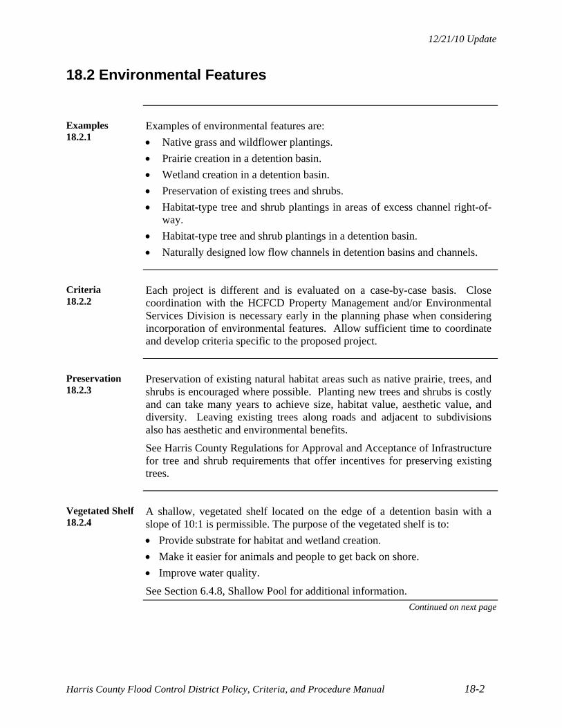
12/21/10 Update
Harris County Flood Control District Policy, Criteria, and Procedure Manual 18-2
18.2 Environmental Features
Examples 18.2.1
Examples of environmental features are:
Native grass and wildflower plantings.
Prairie creation in a detention basin.
Wetland creation in a detention basin.
Preservation of existing trees and shrubs.
Habitat-type tree and shrub plantings in areas of excess channel right-of-way.
Habitat-type tree and shrub plantings in a detention basin.
Naturally designed low flow channels in detention basins and channels.
Criteria 18.2.2
Each project is different and is evaluated on a case-by-case basis. Close coordination with the HCFCD Property Management and/or Environmental Services Division is necessary early in the planning phase when considering incorporation of environmental features. Allow sufficient time to coordinate and develop criteria specific to the proposed project.
Preservation 18.2.3
Preservation of existing natural habitat areas such as native prairie, trees, and shrubs is encouraged where possible. Planting new trees and shrubs is costly and can take many years to achieve size, habitat value, aesthetic value, and diversity. Leaving existing trees along roads and adjacent to subdivisions also has aesthetic and environmental benefits.
See Harris County Regulations for Approval and Acceptance of Infrastructure for tree and shrub requirements that offer incentives for preserving existing trees.
Vegetated Shelf 18.2.4
A shallow, vegetated shelf located on the edge of a detention basin with a slope of 10:1 is permissible. The purpose of the vegetated shelf is to:
Provide substrate for habitat and wetland creation.
Make it easier for animals and people to get back on shore.
Improve water quality.
See Section 6.4.8, Shallow Pool for additional information.
Continued on next page

12/21/10 Update
Harris County Flood Control District Policy, Criteria, and Procedure Manual 18-3
18.2 Environmental Features, Continued
Specific Criteria for Tree and Shrub Plantings 18.2.5
Specific criteria for proposed tree and shrub plantings are:
Plant trees in a channel only if their effect on water surface levels are accounted for in the design and there is no negative impact on water surface levels or erosion.
Maintain a continuous minimum maintenance access of 20-feet wide along both sides of a grass-lined or partially grass-lined channel and around an entire detention basin. The access can be curvilinear provided curves allow for equipment maneuverability. It does not have to be continuous along the top of bank.
Minimum spacing is 7 feet for habitat planting, 15 feet for non-habitat planting, and 20 feet for the maintenance access corridor.
Do not plant trees and shrubs in backslope drainage systems.
Trees and shrubs may be planted individually or in clusters along the top of bank only if spaced 20 feet apart to allow equipment access to the entire side slope.
Include plant species (common and botanical), size, number, and spacing in planting plans sealed by a landscape architect.
If temporary irrigation systems are included, contact HCFCD for criteria.
For planting standards and specifications, contact HCFCD.
For typical tree locations on benched channel sections, see Exhibit 18-1.
Trees 18.2.6
Adaptable, native trees are recommended to reduce maintenance costs and increase survivability. Some trees to consider are:
Shumard Oak Willow Oak Water Oak Nuttal Oak Sweetgum Bald Cypress River Birch Cedar Elm Green Ash Southern Magnolia Texas Palm Drummond Red Maple Black Gum Red Cedar Sycamore American Holly
Shrubs 18.2.7
Some native shrubs small understory trees to consider are:
Wax Myrtle Yaupon (female) Redbud Parsley (Green Hawthorne) Red Buckeye Button Bush Beauty Berry Dwarf Palmetto Roughleaf Dogwood

12/21/10 Update
Harris County Flood Control District Policy, Criteria, and Procedure Manual 18-4
18.3 Recreation Features
Examples 18.3.1
Examples of recreation features are:
Hike and bike trails.
Nature trails and other passive recreation features.
Sports fields in detention basins.
Picnic and open field play areas in detention basins.
Fishing ponds.
Criteria 18.3.2
Each project is different and is evaluated on a case-by-case basis. Close coordination with the HCFCD Property Management and/or Environmental Services Division is necessary early in the planning phases when considering incorporation of recreational features. Allow sufficient time to coordinate and develop criteria specific to the proposed project. The HCFCD Property Management Department confirms the project feasibility and the HCFCD Project Review Section approves the project construction drawings.
Specific Criteria for Trails 18.3.3
Specific criteria for proposed trails are:
Design and construct the trail so maintenance equipment can drive on or over the trail if it is in the 20 foot maintenance access corridor.
Do not put trails in backslope drainage systems.
Maintain conveyance in the backslope swale if the trail crosses the backslope swale.
Design trail such that water does not pond adjacent to the trail from local runoff.
Do not place bollards or permanent structures in the HCFCD right-of-way which would prohibit HCFCD access.
Railing is not permitted along the top of bank.
Gates are permissible at access points provided they include a HCFCD lock.
No utilities, utility lines, or irrigation lines are permitted in the HCFCD right-of-way.
Trails can be in channels or detention basins provided they do not hinder maintenance equipment access.
If applicable, design and construct in accordance with Americans with Disabilities Act (ADA) and other applicable state and federal laws.

12/21/10 Update
Harris County Flood Control District Policy, Criteria, and Procedure Manual 18-5
18.4 Aesthetic Features
Examples 18.4.1
Examples of aesthetic features are:
Preservation of existing trees.
Landscape-type tree and shrub plantings.
Horizontal and vertical curvilinear contouring of detention basins.
Variations of the side slopes of detention basins.
Variations of the side slopes and horizontal alignment of channels.
Composite channel sections.
Aesthetic design of hydraulic structures and erosion control.
Specific Criteria 18.4.2
Each project is different and is evaluated on a case-by-case basis. Close coordination with the HCFCD Property Management and/or Environmental Services Division is necessary early in the planning phase when considering incorporation of aesthetic features. Allow sufficient time to coordinate and develop criteria specific to the proposed project. The HCFCD Property Management Department confirms the project feasibility and the HCFCD Project Review Section approves the project construction drawings.


12/21/10 Update
Harris County Flood Control District Policy, Criteria, and Procedure Manual 19-1
SECTION 19 – REPORT REQUIREMENTS
19.1 Introduction
Overview 19.1.1
A drainage or design report is important to confirm a proposed project is designed in accordance with the policies, guidelines, and criteria in this manual and sound engineering practice. The report communicates the justification of the drainage plan or design for review and approval purposes, and is a reference document for others in the future who want to perform additional work in, on, over, under, or adjacent to the same HCFCD facility.
Purpose of Reports 19.1.2
The purpose of a drainage or design report is to document, identify, and resolve as many design issues as possible early in the project development phase in order to facilitate completion of the construction drawings and a successful project.
Report Content 19.1.3
Prepare clear, concise, and complete reports for the proposed project that:
Cover applicable topics.
Explain the decisions made.
Indicate where and why criteria were not followed.
Summarize pertinent information and data.
Include tables, maps, exhibits, photographs, calculations, etc. Exhibits 19-1 and 19-2 are examples of a plan view and profile view for a proposed channel conveyance project.
The length of the report is not important provided the applicable design topics are covered clearly and completely.
It is suggested that reports over ten pages be bound.
Texas State Board of Registration for Professional Engineers Requirement 19.1.4
All reports submitted to HCFCD must be properly identified, sealed, signed, and dated as required by the Texas State Board of Registration for Professional Engineers.
Reports submitted for preliminary review must be clearly labeled as preliminary and comply with Texas State Board requirements.
Continued on next page

12/21/10 Update
Harris County Flood Control District Policy, Criteria, and Procedure Manual 19-2
19.1 Introduction, Continued
Submittal Requirements 19.1.5
For all drainage and design reports submitted to the HCFCD, follow the current electronic submittal guidelines posted on the Harris County Permit’s website.

12/21/10 Update
Harris County Flood Control District Policy, Criteria, and Procedure Manual 19-3
19.2 Report Outline
Report Outline 19.2.1
To facilitate preparation and review of drainage and design reports, an outline for a typical new development project is provided below. Include all applicable sections.
EXECUTIVE SUMMARY (For projects that include detention, include the detention summary table in Section 19.3.1, Detention Summary Table.)
SECTION 1 - INTRODUCTION 1.1 Project Name and Purpose 1.2 Project Limits 1.3 Project Objectives 1.4 Assumptions and Constraints 1.5 Prior Studies
SECTION 2 - EXISTING CONDITIONS 2.1 Location and Topography 2.2 Land Use 2.3 HCFCD Facilities and Unit Numbers 2.4 Right-of-Way 2.5 Pipelines and Utilities
SECTION 3 - HYDROLOGY AND HYDRAULICS 3.1 Analysis Objective 3.2 Hydrologic Methodology 3.3 Hydraulic Methodology 3.4 Pre-Project Conditions
SECTION 4 - PROPOSED DRAINAGE PLAN 4.1 Description 4.2 Hydrological Analysis 4.3 Hydraulic Analysis 4.4 Channel and/or Detention Layout 4.5 Right-of-Way Requirements 4.6 Special Erosion Control Features 4.7 Stormwater Quality Features 4.8 Potential Pipeline and Utility Conflicts 4.9 Geotechnical Requirements 4.10 Environmental Issues 4.11 Maintenance Access Plan Requirements 4.12 Operation Plan for Pumped Detention Basins 4.13 Other Considerations
Outline Continued on next page

12/21/10 Update
Harris County Flood Control District Policy, Criteria, and Procedure Manual 19-4
19.2 Report Outline, Continued
Report Outline Continued 19.2.1
MAPS AND EXHIBITS
Vicinity Map
Drainage Area Map
Project Area Map, Showing Existing and Proposed:
– Land Use
– Topography/Grading
– Drainage Facilities (Public and/or Private)
– Right-of-Way
– Floodplain Limits
– Stationing Used in Hydraulic Calculations
Hydraulic Profile Showing:
– Existing and Proposed Flowlines, Bottom Widths, and Side Slopes
– Typical Natural Ground Elevations at the Right-of-Way Lines
– Existing and Proposed Bridge, Culvert, Utility, and Pipeline Crossings
– Locations of Major Confluences
– Drop Structures, Transitions, Inflow and Outflow Structures, Stormwater Quality Features, and other Items Influencing the Plan
– Existing and Proposed 1% and 10% Exceedance Probability Water Surface Profiles and Other Frequencies As Appropriate
– Datum and Year of Adjustment
Existing and Proposed Cross-Sections, Including Datum and Year of Adjustment
Existing and Proposed Hydrographs at Critical Locations
APPENDIX
Detailed Hydrological Calculations
Detailed Hydraulic Calculations
Geotechnical Report
Environmental Site Investigation/Assessment Report
Maintenance Access Plan
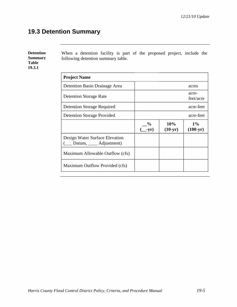
12/21/10 Update
Harris County Flood Control District Policy, Criteria, and Procedure Manual 19-5
19.3 Detention Summary
Detention Summary Table 19.3.1
When a detention facility is part of the proposed project, include the following detention summary table.
Project Name
Detention Basin Drainage Area acres
Detention Storage Rate acre-
feet/acre
Detention Storage Required acre-feet
Detention Storage Provided acre-feet
__% (__-yr)
10% (10-yr)
1% (100-yr)
Design Water Surface Elevation (___ Datum, ____ Adjustment)
Maximum Allowable Outflow (cfs)
Maximum Outflow Provided (cfs)


HARRIS COUNTY FLOOD CONTROL DISTRICT POLICY, CRITERIA, AND PROCEDURE MANUAL
APPENDICES

12/21/10 Update
Harris County Flood Control District Policy and Criteria Manual A- 1
APPENDIX A – RESERVED
A.1 General
This appendix is being reserved for future information regarding drainage criteria from other jurisdictions.

12/21/10 Update
Harris County Flood Control District Policy, Criteria, and Procedure Manual B-1
APPENDIX B - FORMS
1. Preliminary Assessment of HCFCD Requirements
2. Request for Variance from HCFCD
3. Application for Acceptance of Maintenance of a Drainage/Detention Facility by HCFCD
4. 48 Hour Pre-Construction Notification
5. Certification of Construction Completion

12/21/10 Update
Page 1 of 2
PRELIMINARY ASSESSMENT OF HARRIS COUNTY FLOOD CONTROL DISTRICT REQUIREMENTS
Submitted By: Phone: Email: Company: Date: _____________________
Proposed Project Description
Name: ___________________________________________________ Request #: ________________
Type: ______________________________________________________________________________
Location: ________________________________________________________________ (include map)
Size: _______________________________________________________________________________
Existing Condition (show information on map, if available)
Subject Property Land Use: _____________________________________________________________
Adjacent Land Use: ___________________________________________________________________
HCFCD Maintained Facilities: ___________________________________________________________
Drainage Route: _____________________________________________________________________
Historic Flooding: ____________________________________________________________________
Effective Flood Plain and Floodway: ______________________________________________________
Topography: ________________________________________________________________________
Existing Roads: ______________________________________________________________________
Proposed Project Information
For new land developments, include proposed drainage plan.
For non-flood control features, show what is proposed and where.
Existing HCFCD Maintained Facilities Effected: _____________________________________________
New HCFCD Maintained Facility Proposed? ________________________ Where? ________________
Special Design Considerations/ Other Information: _________________________________________ _
___________________________________________________________________________________
___________________________________________________________________________________
___________________________________________________________________________________
___________________________________________________________________________________
(Factors that could affect the storm water management plan, such as jurisdictional wetlands, limited outfall depth, existing drainage problems, existing channel or detention conditions, etc.)

12/21/10 Update
Page 2 of 2
Acceptance Criteria
Prior to consideration for HCFCD maintenance, a final review of the following criteria and items required will be conducted.
HCFCD Criteria Item:
The channel or detention basin receives storm water from a public street or public storm sewer system.
Sealed construction drawings approved by HCFCD.
Project constructed in accordance with the sealed construction drawings.
Responsible engineer submits a construction certification/request for post construction inspection.
Substantially complete construction inspection letter issued by HCFCD.
Access to the facility available for HCFCD inspection and maintenance purposes.
Right-of-way interest conveyed to the HCFCD or dedicated to the public for both the facility and access to the facility.
Appropriate HCFCD turf establishment criteria satisfied.
Facility passes the One-Year Warranty Period inspection.
HCFCD Response/Requirements:
___________________________________________________________________________________
___________________________________________________________________________________
___________________________________________________________________________________
___________________________________________________________________________________
___________________________________________________________________________________
___________________________________________________________________________________
___________________________________________________________________________________
By: _________________________________________ Date: _________________________
Internal Use
Date of HC CC facility Acceptance ________________ Property Management _______________________________ (Date) (Sign and Date) DEV-ID # __________________

12/21/10 Update
REQUEST FOR VARIANCE FROM HARRIS COUNTY FLOOD CONTROL DISTRICT
Submitted By: __________________________ Phone: _____________ Email: _______________
Company: _________________________________________________ Date: _______________
Proposed Project Description
Name:_____________________________________ Request #_______________________
Type: ___________________________________________________________________________
Location:_____________________________________________________________(include map)
Existing Condition (show information on map or drawing)
HCFCD Maintained Facilities:________________________________________________________
Existing Right-of-Way for HCFCD facility: ______________________________________________
Topography: _____________________________________________________________________
Other Pertinent Data Related to Variance Request: ________________________________________________________________________________________________________________________________________________________________ Variance Request
Specific criteria you want to vary: _____________________________________________________ ________________________________________________________________________________
Explain why the criteria needs to be varied or is not applicable: _____________________________ _______________________________________________________________________________ Explain how the basis for the criteria will be satisfied: _____________________________________ ________________________________________________________________________________ List attachments supporting variance request (preliminary design report excerpt, construction drawings, calculations, photographs, maps, etc.): HCFCD to fill in this area DEV ID # _____________
Justification of Decision: _______________________________________________________ ___________________________________________________________________________ Approval of Final Decision: ____________________________ _____________________ (Signature) (Date)
Dept./Section Reviewer Date Comments/Recommendation
Project Review
Property Mgnt
Planning
Environmental
Other
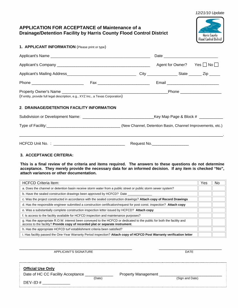
12/21/10 Update
APPLICATION FOR ACCEPTANCE of Maintenance of a Drainage/Detention Facility by Harris County Flood Control District
1. APPLICANT INFORMATION (Please print or type) Applicant's Name ______________________________________________ Date _________________________ Applicant’s Company ___________________________________________ Agent for Owner? Yes No Applicant's Mailing Address________________________________ City ______________ State ______ Zip _____ Phone ________________________ Fax ________________________ Email ________________________ Property Owner's Name _________________________________________________Phone ___________________ (If entity, provide full legal description, e.g., XYZ Inc., a Texas Corporation) 2. DRAINAGE/DETENTION FACILITY INFORMATION Subdivision or Development Name: _________________________________Key Map Page & Block # ___________ Type of Facility:__________________________________ (New Channel, Detention Basin, Channel Improvements, etc.) ______________________________________________________________________________________________. HCFCD Unit No. : _________________________________ Request No._________________ 3. ACCEPTANCE CRITERIA: This is a final review of the criteria and items required. The answers to these questions do not determine acceptance. They merely provide the necessary data for an informed decision. If any item is checked “No”, attach variances or other documentation. HCFCD Criteria Item: Yes No a. Does the channel or detention basin receive storm water from a public street or public storm sewer system? b. Have the sealed construction drawings been approved by HCFCD? Date ______________ c. Was the project constructed in accordance with the sealed construction drawings? Attach copy of Record Drawings d. Has the responsible engineer submitted a construction certification/request for post const. inspection? Attach copy e. Was a substantially complete construction inspection letter issued by HCFCD? Attach copy f. Is access to the facility available for HCFCD inspection and maintenance purposes? g. Has the appropriate R.O.W. interest been conveyed to the HCFCD or dedicated to the public for both the facility and access to the facility? Provide copy of recorded plat or separate instrument.
h. Has the appropriate HCFCD turf establishment criteria been satisfied? i. Has facility passed the One-Year Warranty Period inspection? Attach copy of HCFCD Post Warranty verification letter
____________________________________________________ _____________________________ APPLICANT’S SIGNATURE DATE
Official Use Only
Date of HC CC Facility Acceptance _____________ Property Management _____________________________ (Date) (Sign and Date)
DEV-ID # _____________

Revised 7/26/11
HARRIS COUNTY FLOOD CONTROL DISTRICT 48 HOUR PRE-CONSTRUCTION NOTIFICATION 48 hours prior to beginning work in a HCFCD right-of-way, complete and submit this form and attachments to: Harris County Flood Control District, Property Management Department, Development Coordination and Inspection Section (DCIS), 9900 Northwest Freeway, Houston, Texas, 77092
And email or fax this form to: [email protected], Fax Number: 713/684-4212. If any questions, call 713-684-4116. GENERAL INFORMATION Project Name ______________________________ Date __________________ HCFCD Unit No.____________________________ Request No._____________ Brief Description _______________________________ Key Map Page___________ OUTFALL CHANNEL DETENTION UTILITY OTHER
Proposed Construction Start Date: ________________________ CONTACT INFORMATION
Applicant ________________________________ Phone No. _________________ Contractor _______________________________ Phone No. _________________ Superintendent:
Phone No.: Cell No.:
Consultant Firm ___________________________ Phone No. _________________ Construction Engineer:
Phone No.:
Cell No.:
ATTACHMENTS REQUIRED (check box if attached) Construction Drawings Signed by HCFCD Approval (Notification) to Work within HCFCD Right-of-Way. Notification # _____________ Copy of Corps of Engineers Section 404 individual permit, if applicable. Permit # ________ Copy of Right-of-Way for non-Flood Control Feature, if applicable
Certification that all applicable permits have been obtained _________________________ Applicant Signature THIS FORM DOES NOT CONSTITUTE APPROVAL TO ENTER A HCFCD RIGHT-OF-WAY.
Official Use Only:
Assigned To _________________________________ DEV- ID # ______________

12/21/10 Update
Harris County Flood Control District Policy, Criteria, and Procedure Manual
Certification of Construction Completion
There is not a standard form for the Certification of Construction Completion, therefore do the following. 1. Submit a letter signed and sealed by the owner’s engineer certifying that:
The elevations and grades were taken by an on-site survey on a certain date.
All features and appurtances are constructed to the grade shown on the record drawings and in compliance with specifications.
All pipes, structures, etc. are of the size and dimensions shown on the record drawings.
All improvements are capable of performance as designed by the engineer and approved by the HCFCD.
2. For work in existing HCFCD maintained facilities, certify the facility was restored to as good or better condition than prior to construction.
3. Note all variances previously granted and variances requested as part of this submittal, if any.

12/21/10 Update
Harris County Flood Control District Policy, Criteria, and Procedure Manual C-1
APPENDIX C - CHECKLISTS
C.1 - Construction Drawings with Storm Sewer Outfalls
C.2 - Channel Construction Drawings
C.3 - Detention Basin Construction Drawings
C.4 - Bridge and Culvert Construction Drawings
C.5 - Wastewater Treatment Plant Construction Drawings
C.6 - Pipeline/Utility Crossing Construction Drawings
C.7 - Recreation (including trails), Environmental, and Aesthetic Feature Construction Drawings
C.8 - Plat Checklist

12/21/10 Update
Harris County Flood Control District Policy, Criteria, and Procedure Manual C-2
Checklist C.1 - Construction Drawings with Storm Sewer Outfalls
Plan Title ________________________________________________________ Plan Date _____________
Item √ or N/A
1. Plan title.
2. Vicinity map, north arrow, scale(s), and legend.
3. Date prepared and revised.
4. Official benchmark datum and year of survey adjustment.
5. HCFCD reference unit number(s).
6. Signed and sealed by a licensed Texas Professional Engineer.
7. Standard HCFCD Notes for Construction Drawings.
8. Standard Detail Sheets, as applicable.
9. Overall layout map showing floodplain and floodway limits outside of channel/detention right-of-way.
10. Plan view and cross section view of storm sewer outfall(s) into channel or detention basin.
11. Existing, proposed, and ultimate HCFCD or drainage right-of-way on plan view and cross sections.
12. Right-of-way information, including deed recording volume and page, clerk’s file number, grantee (e.g. HCFCD, Harris County, TxDOT, City, Public, etc.), type (e.g. easement or fee strip), and copies of the recorded deeds.
13. Existing and ultimate channel/detention cross section, including channel/detention high banks, toes, centerline, backslope swales, backslope interceptor structures.
14. 100-year water surface on channel/detention section. (Reference source.)
15. Floodplain and floodway limits outside of channel/detention right-of-way.
16. Existing and proposed utility easements adjacent to and within project.
17. Other information required for specific site conditions or project.
18. Environmental permit determination or letter stating none required.
19. Preservation, repair, or replacement of existing environmental, recreation, or aesthetic features.
20. Digital files.
Drainage or Design Report reviewed. ___ N/A ___ Yes Date _____________________
Geotechnical Report reviewed. ___ N/A ___ Yes Date ______________________
Include this checklist with each submittal. Check (√) if included, or mark “N/A” if item is not applicable.
Engineer ___________________________________________ Date Submitted _____________________
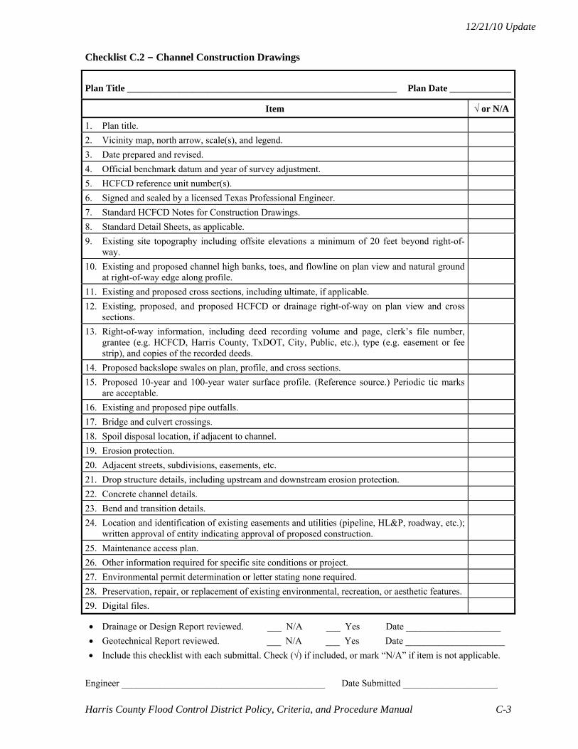
12/21/10 Update
Harris County Flood Control District Policy, Criteria, and Procedure Manual C-3
Checklist C.2 - Channel Construction Drawings
Plan Title _________________________________________________________ Plan Date _____________
Item √ or N/A
1. Plan title.
2. Vicinity map, north arrow, scale(s), and legend.
3. Date prepared and revised.
4. Official benchmark datum and year of survey adjustment.
5. HCFCD reference unit number(s).
6. Signed and sealed by a licensed Texas Professional Engineer.
7. Standard HCFCD Notes for Construction Drawings.
8. Standard Detail Sheets, as applicable.
9. Existing site topography including offsite elevations a minimum of 20 feet beyond right-of-way.
10. Existing and proposed channel high banks, toes, and flowline on plan view and natural ground at right-of-way edge along profile.
11. Existing and proposed cross sections, including ultimate, if applicable.
12. Existing, proposed, and proposed HCFCD or drainage right-of-way on plan view and cross sections.
13. Right-of-way information, including deed recording volume and page, clerk’s file number, grantee (e.g. HCFCD, Harris County, TxDOT, City, Public, etc.), type (e.g. easement or fee strip), and copies of the recorded deeds.
14. Proposed backslope swales on plan, profile, and cross sections.
15. Proposed 10-year and 100-year water surface profile. (Reference source.) Periodic tic marks are acceptable.
16. Existing and proposed pipe outfalls.
17. Bridge and culvert crossings.
18. Spoil disposal location, if adjacent to channel.
19. Erosion protection.
20. Adjacent streets, subdivisions, easements, etc.
21. Drop structure details, including upstream and downstream erosion protection.
22. Concrete channel details.
23. Bend and transition details.
24. Location and identification of existing easements and utilities (pipeline, HL&P, roadway, etc.); written approval of entity indicating approval of proposed construction.
25. Maintenance access plan.
26. Other information required for specific site conditions or project.
27. Environmental permit determination or letter stating none required.
28. Preservation, repair, or replacement of existing environmental, recreation, or aesthetic features.
29. Digital files.
Drainage or Design Report reviewed. ___ N/A ___ Yes Date ____________________
Geotechnical Report reviewed. ___ N/A ___ Yes Date _____________________
Include this checklist with each submittal. Check (√) if included, or mark “N/A” if item is not applicable.
Engineer ___________________________________________ Date Submitted ____________________

12/21/10 Update
Harris County Flood Control District Policy, Criteria, and Procedure Manual C-4
Checklist C.3 - Detention Basin Construction Drawings
Plan Title _________________________________________________________ Plan Date _____________
Item √ or N/A
1. Plan title.
2. Vicinity map, north arrow, scale(s), and legend.
3. Date prepared and revised.
4. Official benchmark datum and year of survey adjustment.
5. HCFCD reference unit number(s).
6. Signed and sealed by a licensed Texas Professional Engineer.
7. Standard HCFCD Notes for Construction Drawings.
8. Standard Detail Sheets, as applicable.
9. Existing and proposed site topography, including offsite elevations a minimum of 20 feet beyond right-of-way.
10. Existing and proposed basin high banks, toes, and flowline on plan view (include profile view for linear detention basins).
11. Existing and proposed cross sections, including ultimate, if applicable.
12. Existing and proposed HCFCD or drainage right-of-way on plan view and cross sections.
13. Right-of-way information, including deed recording volume and page, clerk’s file number, grantee (e.g. HCFCD, Harris County, TxDOT, City, Public, etc.), type (e.g. easement or fee strip), and copies of the recorded deeds.
14. Proposed backslope swales on plans and cross sections.
15. Proposed 10-year and 100-year water surface elevations. (Reference source.)
16. Emergency overflow.
17. Spoil disposal location, if adjacent to basin.
18. Inlet and outlet detail, including erosion protection.
19. Pilot channel detail.
20. Maintenance access indicated.
21. Adjacent streets, subdivisions, easements, etc.
22. Location and identification of existing easements (pipeline, HL&P, roadway, etc.); written approval of entity indicating approval of proposed construction.
23. Service area of basin (map and acreage).
24. Summary table of detention basin volume and release rate computations.
25. Maintenance access plan.
26. Other information required for specific site conditions or project.
27. Environmental permit determination or letter stating none required.
28. Preservation, repair, or replacement of existing environmental, recreation, or aesthetic features.
29. Digital files.
Drainage or Design Report reviewed. ___ N/A ___ Yes Date _____________________
Geotechnical Report reviewed. ___ N/A ___ Yes Date ______________________
Include this checklist with each submittal. Check (√) if included, or mark “N/A” if item is not applicable.
Engineer ___________________________________________ Date Submitted _____________________

12/21/10 Update
Harris County Flood Control District Policy, Criteria, and Procedure Manual C-5
Checklist C.4 - Bridge and Culvert Construction Drawings
Plan Title _________________________________________________________ Plan Date _____________
Item √ or N/A
1. Plan title.
2. Vicinity map, north arrow, scale(s), and legend.
3. Date prepared and revised.
4. Official benchmark datum and year of survey adjustment.
5. HCFCD reference unit number(s).
6. Signed and sealed by a licensed Texas Professional Engineer.
7. Standard HCFCD Notes for Construction Drawings.
8. Standard Detail Sheets, as applicable.
9. Existing and proposed HCFCD or drainage right-of-way on plan view.
10. Right-of-way information, including deed recording volume and page, clerk’s file number, grantee (e.g. HCFCD, Harris County, TxDOT, City, Public, etc.), type (e.g. easement or fee strip), and copies of the recorded deeds.
11. Existing site topography, including offsite.
12. Plan, profile, and section views, with existing and proposed low chord and top of road elevations shown on section view.
13. Headwalls, wingwalls and footings.
14. Concrete channel lining/erosion protection details.
15. Detours and guardrails affecting channel maintenance access.
16. Existing, proposed, and ultimate channel sections.
17. Existing and ultimate 10-year and 100-year water surface elevations. (Reference source.)
18. Existing and proposed outfall pipes and roadside ditch interceptor structures.
19. Channel transition detail, plan and section views.
20. Existing and proposed backslope swales and outfalls.
21. Utility crossings.
22. Show maintenance access to HCFCD channels.
23. Other information required for specific site conditions or project.
24. Environmental permit determination or letter stating none required.
25. Preservation, repair, or replacement of existing environmental, recreation, or aesthetic features.
26. Digital files.
Drainage or Design Report reviewed. ___ N/A ___ Yes Date _____________________
Geotechnical Report reviewed. ___ N/A ___ Yes Date ______________________
Include this checklist with each submittal. Check (√) if included, or mark “N/A” if item is not applicable.
Engineer ___________________________________________ Date Submitted _____________________

12/21/10 Update
Harris County Flood Control District Policy, Criteria, and Procedure Manual C-6
Checklist C.5 - Wastewater Treatment Plant Construction Drawings
Plan Title _________________________________________________________ Plan Date _____________
Item √ or N/A
1. Plan title.
2. Vicinity map, north arrow, scale(s), and legend.
3. Date prepared and revised.
4. Official benchmark datum and year of survey adjustment.
5. HCFCD reference unit number(s).
6. Signed and sealed by a licensed Texas Professional Engineer.
7. Standard HCFCD Notes for Construction Drawings.
8. Standard Detail Sheets, as applicable.
9. Existing and proposed HCFCD or drainage right-of-way on plan view.
10. Right-of-way information, including deed recording volume and page, clerk’s file number, grantee (e.g. HCFCD, Harris County, TxDOT, City, Public, etc.), type (e.g. easement or fee strip), and copies of the recorded deeds.
11. Existing site topography, including offsite elevations.
12. Site layout.
13. Existing backslope swales.
14. Site drainage plan.
15. Pipe outfall profile and channel section for storm sewer and effluent line.
16. 100-year water surface elevation and source.
17. Flood plain and floodway limits outside of channel right-of-way.
18. Adjacent streets, subdivisions, easements, etc.
19. Outfall channel information. (Include base flow level in channel.)
20. Other information required for specific site conditions or project.
21. Environmental permit determination or letter stating none required.
22. Preservation, repair, or replacement of existing environmental, recreation, or aesthetic features.
23. Digital files.
Drainage or Design Report reviewed. ___ N/A ___ Yes Date ______________________
Geotechnical Report reviewed. ___ N/A ___ Yes Date _______________________
Include this checklist with each submittal. Check (√) if included, or mark “N/A” if item is not applicable.
Engineer ___________________________________________ Date Submitted ______________________

12/21/10 Update
Harris County Flood Control District Policy, Criteria, and Procedure Manual C-7
Checklist C.6 - Pipeline/Utility Crossing Construction Drawings
Plan Title _________________________________________________________ Plan Date _____________
Item √ or N/A
1. Plan title.
2. Vicinity map, north arrow, scale, and legend.
3. Date prepared and revised.
4. Official benchmark datum and year of survey adjustment.
5. HCFCD reference unit number(s).
6. Signed and sealed by a licensed Texas Professional Engineer.
7. Standard HCFCD Notes for Construction Drawings.
8. Plan and profile of crossing. (Utility plans no larger than 8.5”x14”.)
9. Crossing located on plan using distance(s) from identifiable landmark(s).
10. Existing site topography, including offsite elevations.
11. Existing, proposed, and ultimate channel section.
12. Existing and proposed pipeline or utility.
13. Existing and proposed HCFCD or drainage right-of-way on plan view.
14. Right-of-way information, including deed recording volume and page, clerk’s file number, grantor, grantee (e.g. HCFCD, Harris County, TxDOT, City, Public, etc.), type (e.g. easement or fee strip), and copies of the recorded deeds, as applicable.
15. Existing and future 100-year water surface for elevated crossings.
16. Owners of utilities and emergency telephone number.
17. Environmental permit determination or letter stating none required.
18. Preservation, repair, or replacement of existing environmental, recreation, or aesthetic features.
19. Digital files.
Drainage or Design Report reviewed. ___ N/A ___ Yes Date _____________________
Geotechnical Report reviewed. ___ N/A ___ Yes Date ______________________
Include this checklist with each submittal. Check (√) if included, or mark “N/A” if item is not applicable.
Engineer ___________________________________________ Date Submitted _____________________
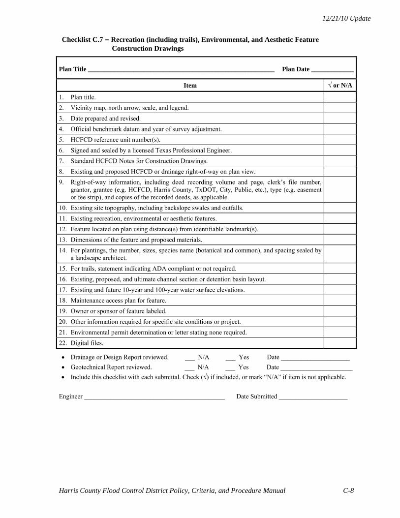
12/21/10 Update
Harris County Flood Control District Policy, Criteria, and Procedure Manual C-8
Checklist C.7 - Recreation (including trails), Environmental, and Aesthetic Feature Construction Drawings
Plan Title _________________________________________________________ Plan Date _____________
Item √ or N/A
1. Plan title.
2. Vicinity map, north arrow, scale, and legend.
3. Date prepared and revised.
4. Official benchmark datum and year of survey adjustment.
5. HCFCD reference unit number(s).
6. Signed and sealed by a licensed Texas Professional Engineer.
7. Standard HCFCD Notes for Construction Drawings.
8. Existing and proposed HCFCD or drainage right-of-way on plan view.
9. Right-of-way information, including deed recording volume and page, clerk’s file number, grantor, grantee (e.g. HCFCD, Harris County, TxDOT, City, Public, etc.), type (e.g. easement or fee strip), and copies of the recorded deeds, as applicable.
10. Existing site topography, including backslope swales and outfalls.
11. Existing recreation, environmental or aesthetic features.
12. Feature located on plan using distance(s) from identifiable landmark(s).
13. Dimensions of the feature and proposed materials.
14. For plantings, the number, sizes, species name (botanical and common), and spacing sealed by a landscape architect.
15. For trails, statement indicating ADA compliant or not required.
16. Existing, proposed, and ultimate channel section or detention basin layout.
17. Existing and future 10-year and 100-year water surface elevations.
18. Maintenance access plan for feature.
19. Owner or sponsor of feature labeled.
20. Other information required for specific site conditions or project.
21. Environmental permit determination or letter stating none required.
22. Digital files.
Drainage or Design Report reviewed. ___ N/A ___ Yes Date _____________________
Geotechnical Report reviewed. ___ N/A ___ Yes Date ______________________
Include this checklist with each submittal. Check (√) if included, or mark “N/A” if item is not applicable.
Engineer ___________________________________________ Date Submitted _____________________

12/21/10 Update
Harris County Flood Control District Policy, Criteria, and Procedure Manual C-9
C.8 - Plat Checklist
1. Identify existing drainage right-of-way (within or adjacent to plat boundary):
Type (fee strip or drainage easement)
Grantee (e.g. HCFCD, Harris County, City, TxDOT, Public, etc.)
Correct recording information – Use volume and page, H.C.M.R., or H.C.C.F. No.
Accurate delineation – Label width and indicate limits
HCFCD unit reference number
Location of existing channel or detention basin high banks
2. Identify public drainage easement being dedicated by this plat:
Label as “Public Drainage Easement”
Accurate delineation – Label width and indicate limits
HCFCD unit reference number
Location of proposed channel or detention basin high banks
Dedication note: “This Drainage Easement is Hereby Dedicated to the Public by this Plat.”
Right-of-way identification example:
3. Include site drainage plan note, if required by HCFCD: "Site drainage plans for the future development of this reserve must be approved by the Harris County Flood Control District.”
This Drainage Easement is Hereby Dedicated to the Public by this Plat.
xxx’ EXISTING ______ PUBLIC DRAINAGE EASEMENT (OR HCFCD FEE STRIP OR EASEMENT) VOL.____ PG.____, H.C.M.R., OR H.C.C.F. NO. _________
HCFCD UNIT NO. XOOO-OO-OO
xx’
(Show high banks, also.)

12/21/10 Update
Harris County Flood Control District Policy, Criteria, and Procedure Manual D-1
APPENDIX D – STANDARDS, DETAILS, AND GUIDELINES
1. HCFCD Digital Submittal Guidelines
2. HCFCD Standard Notes for Construction Drawings
3. HCFCD Standard Interceptor Structure Detail Sheet
4. HCFCD Standard Storm Sewer Outfall and Riprap Detail Sheet
5. HCFCD Standard Concrete Lining Detail Sheet
6. HCFCD Geotechnical Investigation Guidelines

12/21/10 Update
Harris County Flood Control District Policy, Criteria, and Procedure Manual D-2
DIGITAL SUBMITTAL GUIDELINES
Drainage and Design Reports
Follow the current electronic submittal guidelines posted on the Harris County Permit’s website.
Construction Drawings
Submit a CAD file or a GIS shape file referenced to Texas South Central State Plane Coordinates.
Use a grid with scale factor for coordinates.
For CAD files, use a continuous polyline that forms a closed polygon.
Use standard Microsoft Windows fonts.
As a minimum, include the following information:
- Project boundary
- Service area for the detention basin(s) and/or channel(s)
- Detention basin top of bank boundary
- Location of stormwater outfall pipe in HCFCD right-of-way
- Stormwater quality feature location (e.g. trash rack)
- Utility crossing locations
- Bridge crossing locations
- WWTP outfall locations
- Environmental, recreation, or aesthetic features location if within HCFCD right-of-way

12/21/10 Update
Harris County Flood Control District Policy, Criteria, and Procedure Manual D-3
STANDARD HCFCD NOTES FOR CONSTRUCTION DRAWINGS
1. Obtain and comply with all applicable City, County, State, and Federal permits and approvals, with assistance from Engineer, if necessary. Obtain permit (certification) from Harris County Engineer to enter Harris County Flood Control District right-of-way.
2. Notify the Harris County Flood Control District’s Property Management Department in writing at least 48 hours prior to construction. Submit the HCFCD 48 Hour Pre-Construction Notification form, a copy of the approved construction drawings, and a copy of the Corps of Engineers individual Section 404 permit, if applicable, to HCFCD, 9900 Northwest Freeway, Houston, Texas 77092, Attn: Property Management Dept. by hand delivery, or fax to 713-684-4129 (fax number).
3. Engineer shall submit certification letter and record drawings to the Harris County Flood Control District’s Property Management Department requesting inspection of items constructed in Harris County Flood Control District right-of-way. Prior to requesting inspection, the drainage right-of-way and/or easements shall be staked and flagged.
4. Protect, maintain, and restore existing backslope drainage systems.
5. Backslope swale and interceptor structure elevations and locations shown on plans are approximate. Final elevations and locations shall be field verified by the Engineer prior to installation.
6. Establish turf grass on all disturbed areas within the channel or detention right-of-way, except the channel bottom and where structural erosion measures are used. Minimum acceptance criteria are 75% coverage of live Bermuda grass and no erosion or rills deeper than 4”.
7. Backfill in accordance with the Harris County Flood Control District Standard Specification, Section 02315 - Excavating and Backfilling, or equivalent.
8. Excavate channel flowline to design elevation as shown on plans and downstream, as necessary, to ensure no water remains in the facility (storm sewer, lateral channel, or dry bottom detention basin) during normal water surface conditions in the channel, so the facility will function as intended. For wet bottom detention basins, ensure no water is above the design level in the wet bottom during normal water surface conditions in the channel.
9. Maintain flow in channel during construction and restore channel to original condition.
10. Remove all excavated material from the Harris County Flood Control District or drainage right-of-way. No fill is to be placed within a designated flood plain area without first obtaining a fill permit from the appropriate jurisdictional authority.


December 2010
GEOTECHNICAL GUIDELINES
12/21/10 Update
9900 Northwest Freeway Houston, Texas 77092
(713) 684-4000
December 2010
HARRIS COUNTY FLOOD CONTROL DISTRICT GEOTECHNICAL GUIDELINES
TABLE OF CONTENTS
PART 1 - PURPOSE 1 Page
PART 2 - PRELIMINARY INVESTIGATION 2 2.1 REVIEW OF EXISTING INFORMATION 2
2.1.1 Site Geology
2.1.2
2
Fault Evaluation
2.2 VISUAL OBSERVATION AND SURVEY OF THE SITE 2
2
2.2.1 General Site Characterization
2.2.2
2
Ground Survey
2.2.3
4
Channel Hydraulics
4
PART 3 - FIELD EXPLORATION 5 3.1 SOIL BORING AND SAMPLING 5
3.1.1 Boring, Spacing, Depth and Ground Water Measurements
3.1.2
5
Sampling Methods and Intervals
3.1.3
6
Relevant Data and Format of Boring Logs and Data Files
3.1.4
7
Location Map and Soil Profile Drawing(s)
3.1.5
7
Environmental Concerns
3.1.6
8
Site Restoration
3.2 PIEZOMETERS 8
8
3.3 GEOLOGIC FAULT STUDY 9
PART 4 - LABORATORY ANALYSIS 9 4.1 GENERAL REQUIREMENTS AND STANDARDS 9
4.2 SOIL CHARACTERIZATION 10
4.2.1 Description and Classification of Soils
4.2.2
10
Minimum Series of Tests 10

HCFCD Geotechnical Guidelines
December 2010
TABLE OF CONTENTS (cont’d)
4.3 LAB TESTING FOR SPECIFIC INVESTIGATIONS 11
Page
4.3.1 Evaluation of Select Fill Properties
4.3.2
11
Slope Stability/Failure Evaluations
4.3.3
11
Bridge Foundation Design
4.3.4
12
Retaining Wall Design
12
PART 5 - ENGINEERING ANALYSIS AND RECOMMENDATIONS 13 5.1 BORROW MATERIAL ANALYSIS 13
5.2 SLOPE STABILITY ANALYSIS 14
5.2.1 Post-Failure Slope Analysis
5.2.2
15
Examples of Slope Design and Remediation Alternatives
5.2.2.1 Slope Geometry 16
16
5.2.2.2 Retaining Structures 17
5.2.2.3 Mechanical Stabilization 17
5.2.2.4 Soil Nailing 17
5.2.2.5 Soil Improvement 18
5.2.2.6 Geosynthetics 18
5.2.2.7 Drainage 18
5.2.2.8 Cost Estimates for Special Systems 19
5.3 EROSION ANALYSIS 19
5.3.1 Erosion Evaluation
5.3.2
19
Design Considerations
5.3.3
19
Erosion Control Measures
5.4 DRILLED SHAFT AND DRIVEN PILE ANALYSES (HCFCD Projects Only) 20
19
5.5 SEEPAGE AND BOTTOM BLOWUP ANALYSES 21
5.6 RETAINING WALL AND LATERAL EARTH PRESSURE ANALYSES 22

HCFCD Geotechnical Guidelines
December 2010
5.7 INSPECTION AND MAINTENANCE REQUIREMENTS 22
5.7.1 Inspection Requirements
5.7.2
22
Maintenance Schedules
5.8 CONSTRUCTABILITY CONSIDERATIONS 23
22
PART 6 – CONTENT AND FORMAT OF REPORT 24 APPENDICES
Sample of Boring Location Map
Format for Piezometer Installation Diagram
Soils Classification Charts
Format for Boring Logs
Sample of Soil Profile Drawing
Flow Chart for Identification of Dispersive Soils by ASTM D4647 Method A

HCFCD Geotechnical Guidelines
December 2010 Page 1
GEOTECHNICAL GUIDELINES FOR HARRIS COUNTY FLOOD CONTROL DISTRICT
HOUSTON, TEXAS PART 1 - PURPOSE The purpose of the information in this document is to implement a uniform approach to geotechnical investigations for facilities that are to be designed, constructed and/or maintained by the Harris County Flood Control District (HCFCD). The intent of this document is not to supersede the engineering methods and judgment of the engineer, but rather to define a minimum scope of service to be provided and a degree of uniformity in the technical content and format of reports for projects not only funded by HCFCD, but also for privately-funded projects permitted by HCFCD. These guidelines will assist both the geotechnical engineering community and the HCFCD by: 1. Streamlining the review process by clearly outlining the type of information required
and the format of the report. 2. Integrating the experience of the HCFCD with that of the geotechnical engineer to
yield more creative and sound engineering designs. 3. Maintaining consistency in the quality and content of the reports from various
geotechnical engineering consultants 4. Enabling the HCFCD to evaluate the long term performance of particular designs
and the assumptions used in the design. 5. Allowing the creation of a soils database that will expand the utility of the
geotechnical data for both present and future projects. Improvements and revisions will be made to this document over time as necessary to clarify or otherwise improve the information herein. Comments from the geotechnical engineering community and other government agencies are encouraged.

HCFCD Geotechnical Guidelines
December 2010 Page 2
PART 2 - PRELIMINARY INVESTIGATION 2.1 REVIEW OF EXISTING INFORMATION
This phase is intended to familiarize the geotechnical engineering consultant with the previous condition of the site and thus help in better defining the extent of the geotechnical history. Existing data related to the site conditions, provided by the HCFCD, should be gathered and reviewed. This study should include the review of reconnaissance reports, previous geotechnical reports, channel construction plans, site maps and related drawings, geological and fault maps of the area, historical aerial photographs and topographical maps if available, flood and channel flow record data, and other geotechnical reports performed for projects in the vicinity of the current site. Other general information related to the project may also be obtained through various federal, state, and local government agencies such as the U.S. Geological Survey (USGS), Natural Resources Conservation Service (NRCS), Texas Department of Transportation (TxDOT), and local universities. The HCFCD has several reference items including aerial photos, USGS maps, and NRCS Soils Survey maps. These items may be utilized at the HCFCD office but may not be taken off the HCFCD premises.
2.1.1 Site Geology
The site geology description should address parameters of significance to the design, construction or restoration required at the site. Soil formations, soft or unsuitable soils, unusual conditions that are geologically known to exist in the area of the site should be described. Although general knowledge and personal experience may be included, the geological description should focus on researched data related to the project.
2.1.2 Fault Evaluation
If a review of existing information determines that a geologic fault may impact the project, an evaluation of the impact of the fault should be provided in accordance with Section 3.3 Geologic Fault Study.
2.2 VISUAL OBSERVATION AND SURVEY OF THE SITE
2.2.1 General Site Characterization
For channels and basins, the geotechnical engineering consultant should conduct a site observation to become familiar with the existing conditions. The dimensions of the channel cross section should be obtained from the HCFCD or the Design Civil Engineer. The Geotechnical engineering consultant should observe existing structures in the immediate vicinity of the site to evaluate their

HCFCD Geotechnical Guidelines
December 2010 Page 3
potential impact on any failed zone and to assess potential damage to their integrity due to loss of soil. The site should also be observed to evaluate the potential impact (e.g., erosion, slope stability, foundation encroachment) of proposed channel / basin excavations on existing structures. The vegetation such as grass, weeds and trees should be noted with discussion whether vegetation cover is consistent throughout the site. The presence of and nature of existing vegetative cover can aid in evaluating the adequacy of a system for protecting the channel from erosion and can also be used to evaluate the allowable velocity in the channel. Other existing erosion control systems at the site, such as concrete channel lining, articulated concrete blocks, rip rap cover or geosynthetic products should be identified and if any distress is observed within the features, the distress should be noted and preferably documented with photographs. The zone of interest should be clearly assessed and its extent should be defined. In the case of a slope failure, an in depth or detailed description of the failed zone can aid in determining the failure mechanism. Photographs of the failed area are beneficial to understanding the mode of failure. The specific mode of slope failures should be identified. If present, surface cracks commonly known as tension cracks should be identified. If erosion is present, the erosion characteristics and severity of the damage should be assessed and incorporated in the analyses. For bridges, the site characterization should include an observation of existing bridges for obvious signs of settlement, horizontal displacement, other evidence of movement, or soil loss from beneath foundations. The following paragraph defines HCFCD’s specific requirements pertaining to entry on to the site for geotechnical engineering consultants. These site entry requirements pertain only to geotechnical engineering consultants contracted directly with HCFCD under an on-call geotechnical services agreement or a geotechnical consultant serving as a sub consultant to any other organization under direct contract with HCFCD. Prior to entering the site area, it will be the responsibility of the geotechnical engineering consultant to ensure that the HCFCD has arranged for right-of-entry to the site. It will be important that no personnel entry to the site and no drilling/sampling operations be scheduled prior to the HCFCD’s obtaining right-of-entry to the site area. It will be the responsibility of the geotechnical engineering consultant to adequately locate any cables, buried pipelines, or other utilities at the site through the use of the Texas One Call System so any site cables, pipelines, and utilities are not damaged. The geotechnical engineering consultant shall notify the HCFCD at least 48 hours (excluding weekends and/or holidays) prior to the start of the field work so a HCFCD representative can accompany the field crew during the field investigation.

HCFCD Geotechnical Guidelines
December 2010 Page 4
2.2.2 Ground Survey
Survey information will be provided by the HCFCD or the design civil engineer. If no survey is available, a global positioning system should be used to establish boring coordinates. If surveyed cross sections are required for slope stability analysis, the HCFCD or the design civil engineer will provide the survey data. The geotechnical engineering consultant will assist with identifying desired survey locations. The geotechnical engineering consultant should discuss any special survey requirements with the HCFCD or the design civil engineer (for privately funded projects). After the completion of the field work, the geotechnical engineering consultant shall stake the borings so the borings can be located by a surveyor or HCFCD personnel. The stakes at the boring locations should extend at least three feet above the ground surface. Survey flagging should be tied to the stakes and the stakes must be marked with the boring number. Boring locations should be identified, by HCFCD or the design civil engineer, with X-Y coordinates based on Texas State Plane Coordinate System (NAD 83) and surface elevation based on NAVD 1988). References for both horizontal and vertical datums used for the purpose should be included in the geotechnical report.
2.2.3 Channel Hydraulics
Channel hydraulic information will be the responsibility of the HCFCD or the design civil engineer. The geotechnical engineering consultant should indicate channel geometry, slope and special conditions that might impact channel velocity. Such conditions could be channel widening, abrupt change in channel slope, or sharp curves that can induce excessive erosion at localized points of the channel.

HCFCD Geotechnical Guidelines
December 2010 Page 5
PART 3 - FIELD EXPLORATION 3.1 SOIL BORING AND SAMPLING
For HCFCD projects, the location and number of soil borings are typically ascertained as a joint effort by the geotechnical engineering consultant and the HCFCD. For privately-funded projects to be permitted by HCFCD, the location and number of soil borings should be determined as a joint-effort between the geotechnical engineering consultant and the project’s design civil engineer. Generally, the drilling equipment and sampling methods are left to the discretion of the geotechnical engineering consultant. The presentation format of the data in the report and in electronic database form must adhere to HCFCD standards.
3.1.1 Boring Spacing, Depth, and Ground Water Measurements
Soil boring and sampling should be conducted to obtain sufficient information about the subsurface soil stratigraphy and ground water conditions. Borings should be strategically located in the immediate vicinity of the area of interest and away from any existing underlying or overhead utility lines. The number of borings should be selected to optimize the data relative to the site conditions in the area of interest. Borings drilled for channels should be drilled at a maximum spacing of 750 feet unless otherwise approved by HCFCD. A minimum of five borings should be drilled for the first five acres of a detention basin site and an additional boring should be drilled for each additional five acres for detention basin sites. Detention basin sites smaller than five (5) acres in area shall have one (1) boring per acre with a minimum of two (2) borings. It will not be necessary to perform a Geotechnical Investigation for channels or basins that are less than five feet deep. The borings should extend to a depth that will adequately define the substrata soil variations and identify the water bearing layers. As a minimum, the borings should extend to a depth equal to at least 1.75 times the ultimate depth of the channel or basin. If the channel or basin is located adjacent to another existing channel or basin, the boring depths for borings drilled adjacent to the existing drainage facility should be governed by the deeper channel or basin. Borings drilled for retaining walls should be drilled at a maximum spacing of 200 feet and extend to a depth below the wall base to a depth sufficient enough for allowing analysis of global stability, bearing capacity, settlement, sliding and overturning.
HCFCD Geotechnical Guidelines
December 2010 Page 6
A minimum of two borings should be drilled for bridges under HCFCD contracts. For roadway bridges, the borings should extend at least 80 feet below the existing or proposed channel or basin bottom. For pedestrian bridges, the borings should extend at least 40 feet below the existing or proposed channel or basin bottom. Boring depths should be increased by the geotechnical engineering consultant if unusual soil conditions are detected at the site. Borings drilled for bridges should not be terminated in a sand layer. If sand is encountered at the planned bottom of the boring, the boring should be extended, to a depth of at least 15 feet below the original completion depth. The depth at which ground water is encountered during drilling should be measured and recorded. Upon the completion of drilling, the boring should be covered to minimize the flow of surface water into the boring. About 24 hours after the boring has been drilled, the depth to ground water in the boring and the depth to which the boring is open shall be measured and recorded.
3.1.2 Sampling Methods and Intervals
Undisturbed samples should be recovered in cohesive soils using a thin-walled metal tube sampler (minimum 3-inch inside diameter) that complies with ASTM D1587 requirements. For granular soils, standard penetration split-barrel samplers should be used instead with the sampler complying with ASTM D1586 requirements. The sequence of sampling should be continuous for at least the upper 20 feet of the boring and intermittent at 5-foot intervals thereafter. Continuous sampling should also be conducted to at least 10 feet below the estimated failure plane depth when investigating slope failures. If stratification changes are observed during drilling, additional samples should be taken to identify the elevation changes in strata interfaces. The need to obtain additional samples should be based on observation of the drilling process, i.e., noticeable changes to penetration resistance of the auger, changes in the color of wash water, or changes in nature or color of the auger cuttings as a minimum. Similarly, if unusual conditions are encountered, the sampling should be continuous to define the extent of the anomalous layer. All drilling and sampling should comply with the appropriate ASTM standard method.
Special sampling procedures, such as excavating test pits, test trenches, or TxDOT sampling procedures, should be incorporated into the field program if deemed necessary by the geotechnical engineering consultant and should be included in the scope of work. Test pits or test trenches are useful for locating the slope failure plane and for extracting soil samples from various locations within the slope. It may be necessary to use specialized drilling equipment such as portable rigs and swamp buggy rigs in some areas, especially for drilling through steep slopes.

HCFCD Geotechnical Guidelines
December 2010 Page 7
3.1.3 Relevant Data and Format of Boring Logs and Data Files
Geographical locations and depths of borings, time, weather conditions, and methods of drilling should be reported. Ground surface elevation at the boring locations should be shown on the boring logs relative to the survey datum. Northing coordinates (y coordinates) and easting coordinates (x coordinates) should be shown on the boring logs. For granular materials, blow counts for the SPT samples should be recorded. For cohesive soils, pocket penetrometer readings should be taken at the site from undisturbed thin-walled tube samples. Soil descriptions should be based on visual inspection of the samples and the requirements of ASTM D2488. Soil descriptions should include texture of the materials, color, and inclusions such as nodules, stains, organic materials, etc. Layer variations should be recorded when applicable. Fill soils when encountered in borings should be properly identified and described with special reference to the depth, variability, moisture, density and strength aspects. The geotechnical engineering consultant should record the water bearing layers, the depth to ground water during drilling, the depth to ground water about 24 hours after the completion of drilling, and the depth of the open boring about 24 hours after the completion of drilling. Piezometric water level readings should be presented in tabular form with their corresponding reading dates. Any unusual situation such as perched water tables should be reported and seasonal ground water fluctuations should be discussed.
3.1.4 Location Map and Soil Profile Drawing(s)
A boring location map and soil profile drawing(s) must be included in the report. The boring location map should be on sheets no larger than 11" X 17" and can be constructed from a variety of readily available sources such as aerial maps, ground surveys, and USGS Quad maps. The boring location map should be drawn to a convenient engineer’s scale and should clearly show landmarks such as cross streets, channel or creek names, outfalls, or any other permanent feature that can be used to describe the location. A North direction arrow should be provided on every boring location map with proper orientation. Each boring must have reference points or ties so that the exact location of the boring can be recovered. The soil profile drawing(s) should show the subsurface soil and ground water conditions along a line of borings for the full depth of the borings. The line of borings selected for each of the soil profiles should be properly marked or identified on the boring location map. A sufficient number of soil profile drawings should be provided by the geotechnical engineering consultant so a reasonable representation of the subsurface soil and ground water conditions at the site is presented based on the borings drilled. Soil profile drawings should also identify estimated stratification lines, soil classification symbols, flow line or bottom levels

HCFCD Geotechnical Guidelines
December 2010 Page 8
of detention basin or channels, ground surface elevations, any other relevant geographical features such as streets, east, west etc. A summary table of field exploration summary with boring number or identification, depth of boring, ground surface elevation at boring location, coordinates, ground water depth, and cave-in depth should be also included.
3.1.5 Environmental Concerns
Should environmental concerns be identified during geotechnical drilling and no previous provisions for environmental sampling protocol had been provided in the project scope and fee, drilling should cease and the HCFCD or the design civil engineer should be notified. If the project scope includes environmental sampling protocol, the geotechnical engineering consultant is responsible for adhering to all pertinent federal, state, and local regulations and laws.
3.1.6 Site Restoration
It is the responsibility of the geotechnical engineering consultant to clean up the site cuttings and other disturbances resulting from the geotechnical exploration of the site upon completion. In the case of borings through pavements, similar or equivalent materials should be used to restore the site. If borings or Piezometers are backfilled with non-shrink grout, the grout should be placed with a tremie pipe. Backfilling with natural soils is acceptable if materials are not contaminated and methods are in agreement with regulations regarding ground water protection.
3.2 PIEZOMETERS
Where included in the project scope and where suggested appropriate by the encountered soil conditions, Piezometers should be installed. When included in the project scope, repeated measurements should be taken as necessary to evaluate ground water level elevations for use in developing recommendations pertinent to design and construction. If Piezometers were not proposed and water-bearing units were encountered that may impact construction, the HCFCD or the design civil engineer should be notified before completion of the field exploration. For HCFCD projects, the Piezometer should consist of a 3-inch diameter PVC pipe, installed in an oversized diameter borehole as shown on the typical Piezometer installation diagram provided in the Appendix.

HCFCD Geotechnical Guidelines
December 2010 Page 9
3.3 GEOLOGIC FAULT STUDY
The HCFCD or civil design engineer should be notified after completion of the preliminary study (review of existing information) if a Phase I geologic fault study appears to be warranted and if the Phase I fault study has not been included in the project scope and fee. If a review of existing information suggests that a fault may impact the project, a Phase I fault study should be performed as defined by the March 1985 Houston Geological Society (HGS) Bulletin technical article entitled “Investigation of Surface Faults in Texas Gulf Coast Region”. If the results of the Phase I fault study show sufficient evidence of the presence of a fault at the site, HCFCD should be notified so a Phase II fault study could be undertaken as described in the above-referenced March 1985 HGS bulletin. A Phase II fault study requires the collection and analysis of existing geophysical logs and/or the drilling and logging of new geophysical borings. If the Phase II fault study establishes the presence of a fault at the project site, a topographic survey should be performed and additional geophysical borings drilled/logged as part of a Phase III fault study as required by the above-referenced March 1985 HGS bulletin. The location and width of the fault zone, strike, and dip of the fault should be evaluated. Prediction of the movement of the fault should be formulated and the impact of fault activity on site structures or channel flow should be assessed.
PART 4 - LABORATORY ANALYSIS 4.1 GENERAL REQUIREMENTS AND STANDARDS
Geotechnical Laboratories performing HCFCD projects should at minimum meet the requirements specified in the latest revision of A2LA document, R209, “Specific Requirements for Harris County/Houston, Texas: Geotechnical Engineering Testing Laboratory Accreditation Program”
The purpose of the laboratory analysis is to evaluate the soil classification, soil stratigraphy, and the relevant engineering properties of the soils. Tests should be conducted and combined with geologic information to classify the soils and evaluate the stratification. The selection of appropriate laboratory tests beyond the minimum series of tests (outlined below) is typically left to the discretion of the geotechnical engineering consultant. However, the laboratory testing plan should be discussed with the HCFCD or the design civil engineer (for privately funded projects) prior to the field phase to verify the scope of the investigation.
Laboratory tests should be conducted in accordance with the corresponding ASTM standards. Standards other than ASTM standards may be used only with the approval of the HCFCD. For soil description, only ASTM classification

HCFCD Geotechnical Guidelines
December 2010 Page 10
nomenclature is acceptable. The ASTM standard soil designation is given in the Appendix. Boring logs should bear all relevant standard data for classification purposes and be submitted in the format shown in the Appendix. For HCFCD projects, all soil data from the boring logs, field tests, and lab tests shall be submitted in a database format approved by the HCFCD using an electronic media acceptable to the HCFCD such as a compact disc. This database must be compatible with input format of files used by “gINT” software.
4.2 SOIL CHARACTERIZATION
4.2.1 Description and Classification of Soils
The physical description of the soil layers should include consistency, color, plasticity, moisture and any noticeable inclusions. The subsurface stratification should be clearly defined and soils should be classified according to the flow chart provided in ASTM D2487 standard and to laboratory tests results. The HCFCD requires that the boring log soil descriptions be in the order of the ASTM classification and group symbol [e.g. Fat Clay (CH)], followed by the consistency [e.g. stiff, very stiff, loose, etc], followed by a descriptor for plasticity [e.g. slight plasticity, highly plastic, etc], followed by the color, followed by a description of the moisture conditions. An example of boring log soil descriptions required by the HCFCD is provided on the boring log in the Appendix. The consistency of cohesive soils shall be described as very soft, soft, firm, stiff, very stiff, or hard. The consistency (relative density) of cohesionless soils including silts shall be described as very loose, loose, medium dense, dense, and very dense. Soil descriptions should also be shown on soil profiles taken through the boring locations so as to represent the site subsurface soil conditions. The site soils should be shown on soil profiles. An example of a typical profile is shown in the Appendix.
4.2.2 Minimum Series of Tests
Relevant soil parameters should be given for every layer. These parameters include strength data, classification test results, and moisture content. For cohesive soils, Atterberg limits, dry density, unconfined compressive strength, and minus 200 sieve tests should all be performed on the sample within each distinct layer. For granular soils, minus 200 sieve tests should be conducted. Engineering properties such as shear strength can be estimated using pocket penetrometer and/or torvane tests for cohesive soils and SPT blow counts for granular soils. Stress strain curves and stress paths should be attached for triaxial (CU) tests. CU test results should be accompanied by test data including principal stresses at failure, pore pressures, strain rate, and strain at failure, Atterberg limits, specific gravity, void ratio and degree of saturation at minimum.

HCFCD Geotechnical Guidelines
December 2010 Page 11
Mohr’s failure envelope should be plotted with same scale on x-axis (principal stress) and y-axis (shear stress). A combination of crumb and pinhole tests should be performed to evaluate the presence of dispersive soils at the site. Pinhole tests should be performed in accordance with ASTM D4647 Method A. The flow chart provided in Appendix may be used in the performance of pinhole tests. Test datasheets with complete observations should be attached for the pinhole and hydrometer tests.
4.3 LAB TESTING FOR SPECIFIC INVESTIGATIONS Certain types of investigations will require additional laboratory analysis beyond
the minimum series of tests. These investigations include fill evaluation, slope stability/failure evaluations, bridge foundation design and retaining walls. All specialized laboratory data should be presented in graphs or in charts on separate forms.
4.3.1 Evaluation of Select Fill Properties
The geotechnical engineering consultants may be asked to perform a geotechnical study to evaluate properties of soils at potential borrow sites for use as select fill material. The borrow material may be used in a variety of typical HCFCD maintenance projects such as erosion repairs, slope failure repairs, and fill placement. Because the soil will be excavated and recompacted at another location, shear strength tests should be done using remolded samples rather than undisturbed samples. The remolded samples should be compacted to a pre-established density.
4.3.2 Slope Stability/Failure Evaluations
For slope stability analyses, unconsolidated undrained and consolidated undrained triaxial tests with pore pressure measurements should be conducted to evaluate shear strength properties. Stress-Strain curves should be included especially for the case of post failure analyses. Because of multiple shrink/swell cycles, soil strength (primarily the cohesion component) in channels tends to naturally decrease over time and the fact that slope repair projects typically consist of recompacted soils, the residual shear strength of the soil in slope failure areas should be determined and should be used to analyze slope stability for soils that are susceptible to strength loss with time as a result of shrinkage/swelling due to moisture content variations and the plasticity characteristics of the soil, or for soils that are susceptible to progressive slope failures. Slope stability analyses must be performed utilizing a computer software application appropriate for the purpose such as Geostudio (Slope/w), Slide, UTEXAS, FoSSA etc., or any other software with similar capabilities. A non-

HCFCD Geotechnical Guidelines
December 2010 Page 12
circular slip surface may need to be analyzed for stability in certain cases of slope failure evaluations.
4.3.3 Bridge Foundation Design
For the design of bridge foundations, the geotechnical engineering consultant should conduct unconsolidated undrained triaxial tests to estimate shear strengths used to compute skin friction and end bearing capacities for drilled shafts or driven piles. In addition, if cohesionless soils occur at the bridge foundation areas, the geotechnical engineering consultant should estimate the D50 of cohesionless soils so that a hydraulic engineer can estimate scour around the bridge foundations.
4.3.4 Retaining Wall Design
The design of retaining walls requires the evaluation of short term and long term lateral earth pressures. To develop the input parameters for the short and long term lateral earth pressure analyses, the geotechnical engineering consultant should perform consolidated undrained triaxial tests with pore pressure measurements.

HCFCD Geotechnical Guidelines
December 2010 Page 13
PART 5 - ENGINEERING ANALYSIS AND RECOMMENDATIONS The goal of the engineering analysis is to provide the HCFCD with enough detailed information to guide the design of the project. This information should be an interpretation of the field and laboratory data applied to the purpose of the project. Design information may include the results of slope stability analyses, erosion analyses, drilled shaft or driven pile analyses, shallow foundation analyses, ground water mitigation evaluations, earth pressure distribution analyses, retaining wall analyses, and general soil suitability evaluations. In many cases, the geotechnical engineering consultant should be required to propose several design alternatives. Constraints on the design will be given by the HCFCD, although the geotechnical engineering consultant should attempt to identify additional constraints. In situations where a Geotechnical engineering report is developed much ahead (several months or years of time) of the final design of the facility, the geotechnical report should be updated, to ensure the report reflects and addresses the actual design conditions being proposed at the time of design and construction. The sections below provide requirements for common types of geotechnical engineering projects: borrow material analyses, slope stability/failure analyses, erosion analyses, drilled shaft and driven pile analyses, retaining wall analyses, seepage and excavation bottom blowup analyses, evaluations of requirements for inspection and maintenance, and constructability evaluations.
5.1 BORROW MATERIAL ANALYSIS
The geotechnical engineering consultant’s engineering analysis of potential borrow material should address each of the following questions:
1. Does the soil meet the current HCFCD fill specification? 2. For what types of applications is the fill best suited? 3. For what applications is the fill least suitable? 4. Does the soil meet current TxDOT fill specifications?
Borrow material analysis should consider typical HCFCD applications such as erosion repair, slope failure repair, and use as topsoil. Classification tests, dispersive tests, and permeability tests should be performed to help identify the dispersive nature of the soils. Also, the sensitivity of the soil to loss of shear strength in a disturbed condition should be considered using remolded shear strength tests with a pre-established density. Recommendations for the suitability of the materials for uses such as those described above should be made relative to soil strength, shrinkage cracking, and erodability.

HCFCD Geotechnical Guidelines
December 2010 Page 14
5.2 SLOPE STABILITY ANALYSIS
Slope stability analysis should be performed on selected (critical) geometric sections of channels and detention basins based on the plans or proposed designs provided by the design civil engineer. In addition to verifying the stability of proposed slopes, the steepest allowable stable slopes should be investigated for all HCFCD projects. Slope stability analyses should include both safety against local and global failure of slopes. Methods selected by the geotechnical engineering consultant for the slope stability analyses should be described in the report. Relevant geotechnical assumptions and limitations should be clearly stated. Design (input) parameters such as cohesion, angle of internal friction, etc. should also be presented along with the source of each parameter. Unless otherwise approved by the HCFCD, the geotechnical engineering consultant should be required to develop input parameters for analysis from laboratory tests conducted on soil samples obtained from on-site borings or test pits/trenches. Other parameters such as critical ground water elevations are left to the discretion of the geotechnical engineering consultant.
A summary table of design (input) soil parameters utilized for the slope stability analysis including stratum number, elevation, plasticity index, liquidity index, shear parameters should be presented for the selected location(s) or section(s) considered for analysis. Backup calculations associated with the design parameter estimation, where applicable, should be also attached in the appendix. Criteria or reasons used in the selection of critical section(s) or boring(s) for slope stability analysis should be explained.
Slope stability analyses should only be performed by using acceptable engineering software such as Geostudio (Slope/w), Slide, UTEXAS, FoSSA, etc., or other software with similar capabilities (with prior approval of HCFCD). The estimated slope failure or slip surface for the most critical safety factor should be shown on a profile of the analyzed slope as part of the computer output. If provided, elevation data should be used in the geometric modeling of slope stability analysis. When performing slope stability analyses, the following shear strength parameters should be used for analysis.
Undrained cohesion (cShort Term Condition:
u
) from an unconsolidated undrained triaxial test (ASTM D2850)
HCFCD Geotechnical Guidelines
December 2010 Page 15
Effective stress cohesion (c’) and effective stress angle of internal friction (Φ’) from a consolidated undrained triaxial (CU) test (ASTM D4767) with reduction in shear strength as appropriate for loss of shear strength from weathering, and total stress cohesion (c
Rapid Drawdown Condition:
cu) and total stress angle of internal friction (Φcu
) from a CU triaxial test.
Effective stress cohesion (c’) and effective stress angle of internal friction (Φ’) from a CU triaxial test. .
Long Term Condition:
Slope stability under End-of-Construction case and Long Term cases should consider surcharge load intensity on the top of bank and on the bench (shelf) areas due to construction traffic. For typical stability analyses, the value of the surcharge load intensity is 250 psf. Depending on the type of equipment anticipated during construction or maintenance phases, higher surcharge values may need to be analyzed. Whenever slope protection devices such as concrete lining, riprap, gabion mattresses, articulated concrete blocks, etc. are used, slopes should be checked for stability under the influence of the weight of these elements as surcharge. In such scenarios, slope stability models should not rely on the structural resistance of these elements for achieving the required safety factor. The HCFCD requires that slope stability analyses be performed for short term, rapid drawdown, and long term conditions. The HCFCD’s criteria for safety factors against slope failures are 1.3 for the short term (end of construction) condition, 1.25 for the rapid drawdown condition, and 1.5 for the long term condition. The geotechnical engineering consultant should also analyze the impact of existing structures on the performance of HCFCD facilities and vice versa and provide appropriate recommendations in the report.
5.2.1 Post-Failure Slope Analysis
The purpose of the post-failure analysis is to evaluate the soil strengths, ground water levels, and external conditions that caused the slope failure. This information is then used to model the proposed repair. The cross section of the slope prior to failure should be used in the model. The configuration of the pre-failure cross section can be estimated from adjacent cross sections, previous construction plans, etc. The variables in the model should be adjusted until the model produces a critical failure plane matching the failure plane observed in the field.

HCFCD Geotechnical Guidelines
December 2010 Page 16
The following questions should be addressed in the analysis: 1. What caused the slope failure? Was it due to a natural decrease in soil
strength or an external event such as a water main break, overbank erosion or toe erosion of the channel bank?
2. What is the failure mode for the existing failure? Is it rotational, shallow sloughing, a wedge failure, etc.?
3. What is the location of the failure plane? 4. Does the failure plane in the post-failure model match the actual location of
the failure plane? 5. Do the model’s back-calculated soil strength parameters match the laboratory
results? 6. Does the proposed repair address and mitigate pertinent geotechnical factors
that caused the original failure? 7. What is the steepest slope that is stable without structural reinforcement?
Repairs of the failed zone should be planned and conducted carefully to reduce the potential for further failures. Materials at the site should be considered for use if they are suitable. Remedial techniques such as load reduction, soil improvement, the use of geosynthetic products, retaining structures, and anchors should be considered. A stability analysis should be performed on the proposed design to ensure an adequate factor of safety.
5.2.2 Examples of Slope Design and Remediation Alternatives
Below is a list of options and design criteria the geotechnical engineering consultant should consider. However, the design alternatives that may be presented by the geotechnical engineering consultant in the report are not limited to the options listed below. The list is intended only as a guide for determining possible repair alternatives. The geotechnical engineering consultant should evaluate which alternatives are feasible and include only those in the report. The geotechnical engineering consultant should discuss possible repair alternatives with the HCFCD prior to performing the analysis. Evaluations could include the following: the constructability of the proposed alternatives with reference to feasibility within the constraints of site conditions; headroom availability (under bridges) where applicable; capacity and availability of equipment; inspection requirements; specifications or criteria for acceptability; troubleshooting during installation etc.
5.2.2.1 Slope Geometry Slope flattening and slope benching are possible geometrical enhancements to a slope to improve its safety factor. The geotechnical engineering consultant should present calculations to assess the extent of the

HCFCD Geotechnical Guidelines
December 2010 Page 17
improvement obtained by adjusting the slope geometry and proposed method of slope repair. 5.2.2.2 Retaining Structures Typical retaining structures can be cantilever or gravity walls, driven pile walls, tied back walls, and drilled shaft walls. The geotechnical engineering consultant should justify the use of the retaining structure and define the type of structure for the particular application. The geotechnical engineering consultant should provide the estimated earth pressure distribution acting against the structure and address the global stability against overturning. Sliding at the toe of a retaining wall should be addressed. For drilled shafts, recommendations for the spacing, diameter and minimum embedment depth of the shafts should be provided. For tied-back walls, recommendations for diameter, angle of inclination, and length of the anchors should be provided. The type of grouting technique should be recommended and the corrosion potential of the soil should be identified. The length of the anchors should extend beyond the surface of the potential failure. Long-term load capacity of the anchors should be discussed, especially if soft cohesive materials are present. 5.2.2.3 Mechanical Stabilization Counterberms can be used to increase the resisting forces. Dimensions and locations of the counterberms should be indicated. Stability against sliding due to the weight increase should be evaluated. If shear keys are used to improve sliding resistance, trenching recommendations should be provided. Mechanical stabilization can also be conducted by using backfill materials with metallic strips, or a geosynthetic geogrid for load transfer purposes. In addition to the evaluation of the stability against sliding and/or overturning, the geotechnical engineering consultant should evaluate the internal stability of the system. 5.2.2.4 Soil Nailing Soil nailing methods such as metal rods driven in the ground or placement of grout in predrilled holes can be used as slope reinforcement. The geotechnical engineering consultant should provide the necessary geotechnical parameters for design of soil nail walls. Design parameters such as length, size, and spacing should be recommended. The analysis should also consider the internal and external stability of the system for the assumed potential failure surface.

HCFCD Geotechnical Guidelines
December 2010 Page 18
5.2.2.5 Soil Improvement Earth material properties can be improved by replacing existing materials or by adding materials to improve shear resistance properties. Materials such as concrete rubble, riprap, concrete channel lining, articulated concrete blocks, gabion mattresses, and geosynthetic systems have been used on HCFCD channels. The geotechnical engineering consultant should justify the use of these materials based on design requirements, availability, and economic considerations. Soil hardening techniques should be used mostly when slopes show signs of deterioration or potential failures. When cement is used to stabilize soil materials, soil-cement ratios should be indicated and compaction levels specified. Subsurface drainage should be included in the design since the pervious properties of natural materials are generally reduced with cement additives. If jet grouting is used, recommendations regarding the sequence of grouting, the number of holes and pressure of grouting should be provided and should be based on the knowledge of the slip surface. Pore pressure build up should be considered when grouting. If lime columns are used to increase cohesive soil strength properties, the shear strength of the stabilized soils should be computed and the lime volumes and the spacing of the columns should be provided based on the potential failure surfaces and the existing soils. 5.2.2.6 Geosynthetics Geosynthetic systems can be used to reinforce slopes, especially after failure has occurred. The geotechnical engineering consultant should provide the parameters needed to design geosynthetic systems, specify the soil parameters, compaction levels, type of geosynthetic products, the length and thickness of the layers, anchoring system, and the geometry of the slope. Global stability analyses should be performed to confirm the stability of the geosynthetic system. 5.2.2.7 Drainage Proper drainage for slopes is important in order to reduce the destabilizing effect of the hydrostatic and seepage forces. The geotechnical engineering consultant will provide recommendations for the geotechnical aspects of the drainage design. Furthermore, proper drainage will reduce erosion and piping. Surface drainage should consider site specific parameters such as subsurface soils, vegetation, geometry of the ground surface (i.e., steepness of the slope being drained) and rainfall intensity. Subsurface drainage should be considered by the geotechnical engineering consultant especially for non-natural slopes and should be intended to improve the factor of safety against
HCFCD Geotechnical Guidelines
December 2010 Page 19
failure by decreasing the hydrostatic forces. Drainage blankets, horizontal drains, and cut-off drains are among the techniques that could be used. Design of such drains should be conducted based on the knowledge of the subsurface water conditions. Filter fabric should be used to reduce clogging of the drains and subsequent deterioration of their long term performance. Construction details and spacing of the drains should be indicated by the geotechnical engineering consultant. If a filter fabric is recommended for use, the geotechnical consultant should provide acceptance criteria or properties of the filter fabric (Geotextile). 5.2.2.8 Cost Estimates for Special Systems For special systems such as Geosynthetics, retaining structures, etc. the geotechnical engineering consultant should provide a cost estimate based on current values of materials and their quantities.
5.3 EROSION ANALYSIS
5.3.1 Erosion Evaluation
The type of erosion and possible sources of erosion should be defined. Examples of erosion include toe erosion from channel flow, rilling or gullying from overbank flow, piping, and sapping due to ground water flow.
5.3.2 Design Considerations
The geotechnical engineering consultant will be provided the estimated channel flow velocities. The geotechnical engineering consultant should provide a general indication of the soil’s susceptibility to erosion by channel flow, ground water flow, rainfall, or runoff by using these flow velocities and the existing soil conditions and ground water conditions. The dispersive nature of the earth materials existing on the banks and the bottom of the channel should be defined.
5.3.3 Erosion Control Measures
Vegetation can be used as a natural cover for soil erosion protection. Mats, blankets, or soil confinement systems can also be used to support the growth of the vegetation or directly as erosion control systems. Recommendations for soil preparation should take into account the system manufacturer’s design specifications. Surface protection measures such as riprap, concrete channel lining, articulated concrete blocks, gabion mattresses, and shotcrete can be used to prevent erosion by infiltration and surface runoff by rainfall or stream erosion.

HCFCD Geotechnical Guidelines
December 2010 Page 20
The geotechnical engineering consultant should address the type of erosion protection system that will be most appropriate for the given site conditions and provide appropriate geotechnical parameters to support the design of erosion control measures being considered. The geotechnical engineering consultant should recommend criteria for design and selection of specific products such as riprap or gabions with filter fabric when recommended as appropriate for erosion control. For the special case of utility, tunnel or underground structures crossing channels, additional protective systems need to be adopted to avoid potential scouring around the structures. If cut-off walls are adopted, the geotechnical engineering consultant should provide the depth, the width and the location of the wall.
5.4 DRILLED SHAFT AND DRIVEN PILE ANALYSES (HCFCD Projects Only) For drilled shaft and driven pile analyses, the geotechnical engineering consultant is required to perform axial capacity, lateral load-deflection, settlement, and scour analyses. Depending upon the needs of the designer, the geotechnical engineering consultant may be required to provide design diagrams showing: • Depth versus allowable unit skin friction, • Depth versus allowable unit end bearing, • Depth versus allowable cumulative skin friction in compression • Depth versus allowable axial capacity in compression, • Depth versus allowable axial capacity in tension or uplift, • Lateral load analysis for fixed and free head conditions including;
• Lateral deflection with depth • Bending moment with depth • Shear force with depth • Pile fixity length • Lateral load vs. deflection curves
• Depth versus dynamic soil resistance for driven piles, • Pile drivability analysis using wave equation model for driven precast piles
including: • Recommended hammer and rated energy • Hammer efficiency and stroke • Driving stresses (compression and tension) in the pile with blow counts • Ultimate resistance versus blow count • Refusal criteria
The geotechnical engineering consultant will be required to provide estimates of local scour (“pier scour”) in clays around drilled shaft and driven pile foundations

HCFCD Geotechnical Guidelines
December 2010 Page 21
and present recommendations for scour protection. The geotechnical engineering consultant will be required to provide D50 values for sands that occur within the upper 15 feet of the channel slope surface or flowline at bridge abutment or interior bent locations. Hydraulic design information will be provided by the design civil engineer or the HCFCD. Drilled shaft and driven pile analyses should take into consideration the influence of group effect, settlement, negative skin friction, and the effect of soil shrink-swell potential on the load carrying capability of the drilled shafts and piles. The analyses should also take into consideration the presence of existing foundations and the influence of existing foundations on the load carrying capability of the drilled shafts and driven piles. Expected or anticipated geotechnical difficulties that may be encountered during the drilled shaft or driven pile installation should be considered and monitoring requirements recommended for the drilled shaft and driven pile installation. The recommended monitoring requirements should be provided to include recommendations of the method(s) used to verify the design bearing values, i.e. use of the wave equation, a pile analyzer, dynamic pile driving formulas, etc. A definition should be defined for the term “refusal” and the minimum acceptable penetration provided for the case when refusal is encountered. Recommendations should be provided concerning specifications that should be used for slurry. Any restrictions should be identified with regard to installation methods based on assumptions made during the capacity analyses, especially with regard to the use of slurry, the allowable depth and diameter of predrilled holes, the limits on the use of casing, and the use and limits of jetting.
5.5 SEEPAGE AND BOTTOM BLOWUP ANALYSES
Depending upon the project requirements, the geotechnical engineering consultant may be required to analyze the capability of a wet pond to retain water and recommend measures that may be used to reduce excess seepage losses. The seepage analyses should define the estimated seepage losses as a result of the infiltration of the wet pool water through the pool-side slope and bottom soils. The geotechnical engineering consultant may be required to provide recommendations for any needed treatment of the wet pool soils to assure retention of the pool waters.
The geotechnical engineering consultant should analyze the potential for bottom blowup at basin or wet pool bottoms as a result of the presence of a high ground water conditions. If the analysis of bottom stability and/or potential bottom blowup indicates that an unstable bottom will occur during construction, the geotechnical engineering consultant should provide recommended measures needed to adequately control ground water during construction operations and any needed treatments required to provide for stable working surfaces during construction.

HCFCD Geotechnical Guidelines
December 2010 Page 22
5.6 RETAINING WALL AND LATERAL EARTH PRESSURE ANALYSES
Retaining wall analyses should evaluate the local and global stability of the retaining walls, the allowable bearing pressure at the base of the retaining walls, the retaining wall settlement, sliding of the retaining walls, and overturning of the retaining walls. An earth pressure distribution diagram for both short term and long term conditions should be provided as part of the retaining wall analyses, and/or the geotechnical engineering consultant should provide design input parameters including active earth pressure coefficients, passive earth pressure coefficients, coefficients for earth pressure at rest, the dry unit weight, wet unit weight, and submerged unit weight of the soil adjacent to the retaining wall, and equivalent fluid unit weights. The geotechnical engineering consultant should perform bearing capacity and lateral earth pressure analyses for reinforced concrete box culverts and headwalls and provide recommended allowable bearing pressures for use in the design of the box culverts and headwalls. The geotechnical engineering consultant should provide design input parameters as described above for retaining walls and a lateral earth pressure diagram or diagrams to be used by the design civil engineer of the box culverts and headwalls.
5.7 INSPECTION AND MAINTENANCE REQUIREMENTS
5.7.1 Inspection Requirements
If the project will require a structured inspection routine, the geotechnical engineering consultant should provide a recommended inspection program based on the nature of the project, on the potential or expected problems during construction, or long-term behavior of the earth structure. For deep foundations, Inspection requirements should be in accordance with the latest revision of the FHWA publication entitled “Drilled Shafts: Construction Procedures and Design Methods” and “Design and Construction of Driven Pile Foundations.” If specialized equipment is required, the application, installation methods, locations, and data to be collected should be specified. An inspection schedule covering construction and post-construction phases of the project should be recommended by the geotechnical engineering consultant. Technical data records should be provided to check design assumptions and readjust maintenance schedules. Recommendations for piezometric level readings should be specified to check subsurface drainage performance.
5.7.2 Maintenance Schedules
Recommended maintenance schedules should be submitted for structures or systems requiring periodic maintenance to address potential geotechnical concerns. The goal of a maintenance program is to prolong the life of a system and thus lower long term costs.
HCFCD Geotechnical Guidelines
December 2010 Page 23
5.8 CONSTRUCTABILITY CONSIDERATIONS
The geotechnical engineering consultant should address potential problems that may occur during construction. Such problems could be related to unstable soils that are not capable of supporting construction equipment, limited headroom for construction equipment, detention basin and wet pool bottom stability and blowup, slope stability during excavation, excavation stability and protection by appropriate methods such as sheet piled walls and braced walls, ground water control and dewatering requirements, soil compaction, soil improvement or slope repair, especially in the case of heavy equipment operating near excavation areas during construction. The geotechnical engineering consultant should consider appropriate construction techniques and equipment types required by the proposed design.

HCFCD Geotechnical Guidelines
December 2010 Page 24
PART 6 - CONTENT AND FORMAT OF REPORT The geotechnical report should be presented in substantial accordance with the following Table of Contents format for HCFCD projects. Transmittal letter with P.E. stamp and approval signatures for final report. EXECUTIVE SUMMARY This section should include project description, general summary of investigation, subsurface and groundwater conditions, recommendations for design, recommendations for control of ground water, constructability considerations or any limitations, and recommendations for further study, if necessary. INTRODUCTION Name of department and person authorizing the report Date of authorization Brief background information about the project PURPOSE & SCOPE OF WORK Project Description
Description of project should be such that the project location can be clearly identified. A vicinity map should be provided with appropriate key map numbers.
Description of the proposed facilities including length, depth, width, acreage, and other detailed descriptions
Note: Geotechnical report should include most recent drawings provided by civil engineering consultant for the subject facilities for which the report has been developed.
Scope of the work to be done in the report SITE EXPLORATION Physical description of area Geology Faults (if applicable) FIELD EXPLORATION Soil borings and sampling Piezometer installation
Piezometer installation diagram should be as shown in the Appendix. Environmental issues (If applicable) LABORATORY TESTING Tests performed (with related ASTM standard numbers) Table of results

HCFCD Geotechnical Guidelines
December 2010 Page 25
DESCRIPTION OF SUBSURFACE SOIL AND GROUND WATER CONDITIONS Description of soil stratigraphy Description of ground water conditions Description of soil properties for each soil layer ENGINEERING ANALYSIS AND RECOMMENDATIONS Description of engineering methods and assumptions Basis for selection of soil parameters for analysis purposes and their source /
interpretation of lab results Borrow material analysis Slope stability analysis Post-failure analysis Discussion of repair alternatives Scour analysis Drilled shaft and driven pile analyses Seepage and bottom blowup analyses Retaining wall analyses Inspection and maintenance requirements Erosion analysis Constructability considerations REFERENCES A list of engineering references and citations utilized in the engineering analyses should be listed. A copy of the reference document also should be attached with the report. If the reference material is very large, relevant sections or pages from the reference may be attached. APPENDICES Site Map Boring Location Plan Fault Study (if applicable, as a separate report) Lab Test Results Boring Logs in gINT Format Soil Profile Drawing(s) Showing Soil and Ground Water Conditions Engineering Data Slope Stability Computer Input and Output Backup Data for Calculations Electronic Media Acceptable to the HCFCD Containing Boring Logs The title of the report should identify if the report is a draft or final report and include the Requested Service number, the Purchase Order number under which the report was prepared, the HCFCD Project ID number, and the HCFCD Unit number. All drawings, including stability analysis computer output, shall be at a convenient scale (i.e. at a scale available on a standard triangular engineer scale). For HCFCD projects, all boring logs must be in gINT format.

HCFCD Geotechnical Guidelines
December 2010 Page 26
The geotechnical engineering consultant is required to submit two copies of a draft report for review and five copies of a final report incorporating review comments. The final report must be sealed by a professional engineer licensed in the state of Texas. The draft report may be bound and the final report should be submitted with one copy in a white 3-ring binder labeled on the front and spine and four copies that are spiral bound. After the final report has been received, the HCFCD will review the final report to assure that comments made on the draft report have been incorporated into the final report. After any revisions necessary have been made in the final report and the final report has been accepted by the HCFCD, the final report shall be submitted in its entirety on a compact disk or other electronic media specified by the HCFCD. The final report should be provided to the HCFCD within a negotiated time after receipt of the HCFCD’s comments. While the project is active, i.e. prior to submittal of draft report, on each Friday during the progress of the work, the geotechnical engineering consultant must provide a weekly progress report to the HCFCD. The weekly progress reports should be entitled “Weekly Progress Report, Week Ending …, Geotechnical Investigation for HCFCD Project ID#..............”. The weekly progress reports are a part of each project and should be issued by the licensed professional engineer in charge of the project.

HARRIS COUNTY FLOOD CONTROL DISTRICT GEOTECHNICAL GUIDELINES
APPENDICES


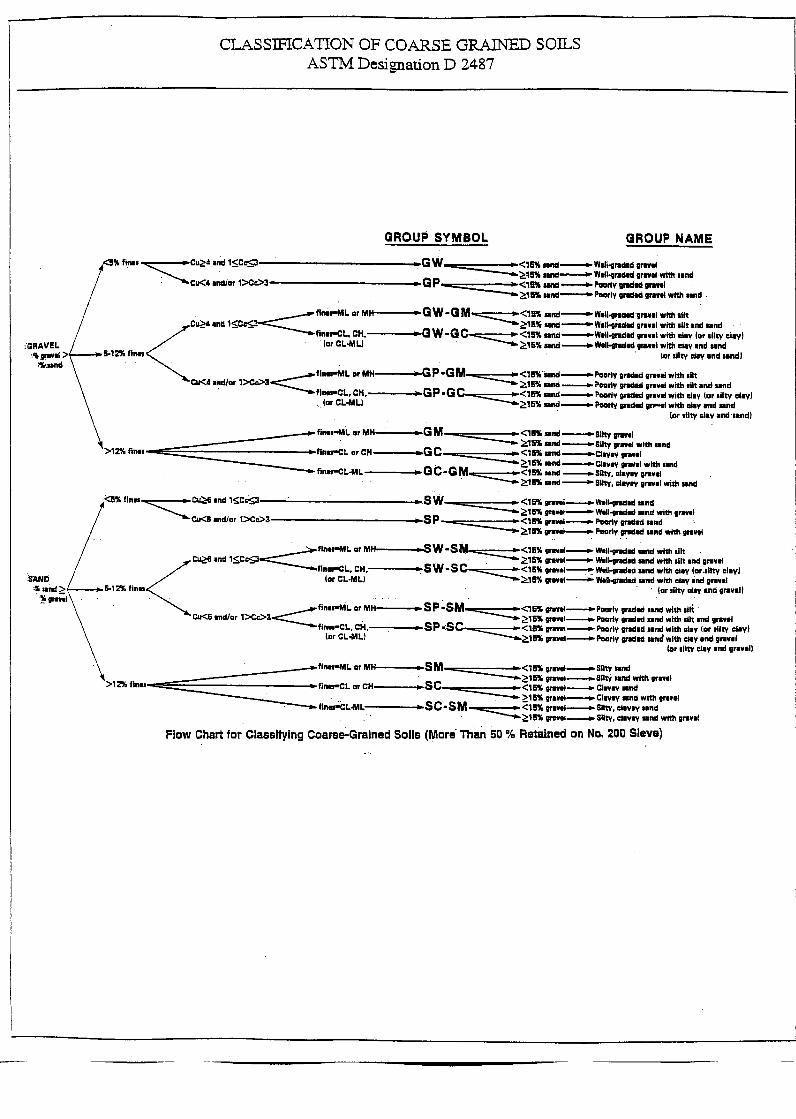
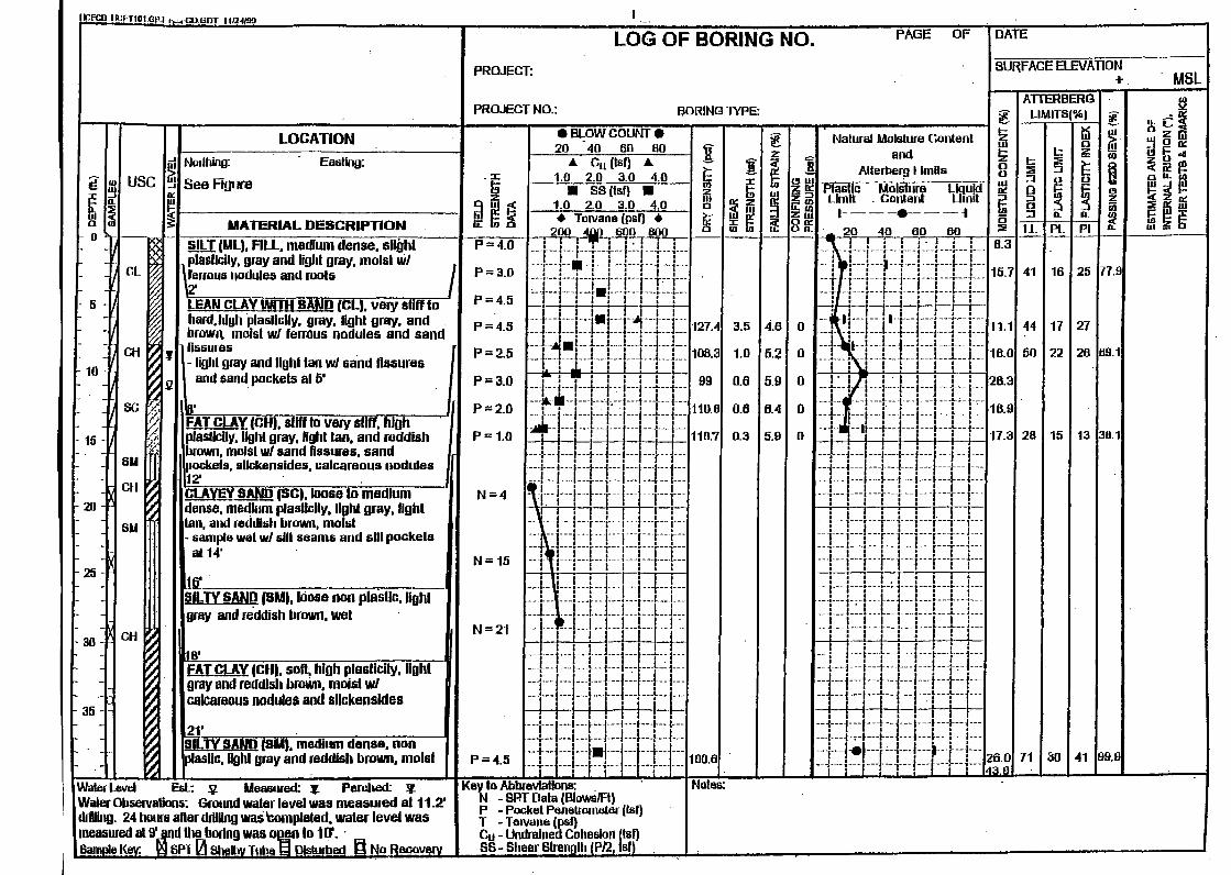


ASTM D4647 METHOD A
GO TO STEP 2CONTINUE FOR
ADDITIONAL 5 MINUTES
NO
Hole Size > Twice Needle Diameter?
D1HIGHLY
DISPERSIVE
YES
RERUN TEST
NO
STEP 1CYCLE LENGTH 5 minutes
HEAD 50mm (2 in.)
Effluent Color Dark?
NO
D2DISPERSIVE
1.0 to 1.3 mL/sSTEP 2
CYCLE LENGTH 5 minutesHEAD 50mm (2 in.)
STOP TESTDETERMINEFLOWRATE
DETERMINE HOLE SIZE
Exceeds 1.5 Needle Diameters
DETERMINE HOLE SIZE
ND4MODERATELY DISPERSIVE
Less Than or Equal to 1.5 Needle Diameters
RAISE HEAD TO 180 mm
GO TOSTEP 3
YES
NO
STEP 3CYCLE LENGTH 5 minutes
HEAD 180mm (7 in.)
RAISE HEAD TO 380 mm
GO TO STEP 4
YES
YESND3
SLIGHTLY TO MODERATELY DISPERSIVE
STOP TESTDETERMINE HOLE SIZE
Greater Than or Equal To 1.5 to 2 Needle Diameters
Effluent Color Darkened OR Flowrate Increased to 1.8 to 3.2
mL/s?
STEP 4CYCLE LENGTH 5 minutes
HEAD 380mm (15 in.)
ND3SLIGHTLY TO MODERATELY DISPERSIVE
STOP TEST
YES
0.8 to 1.0 mL/s
NO
YES
Effluent Very Slightly Dark
AND Flowrates = 0.4 to 0.8 mL/s?
NO
STEP 5CYCLE LENGTH 5 minutes
HEAD 1020mm (40 in.)
YES ND2NONDISPERSIVE
ND1NONDISPERSIVE
RAISE HEAD TO 1020 mm
GO TO STEP 5
YES
YES
Effluent Color Distinctly Dark AND
Flowrate = 1.4 to 2.7 mL/s?
Effluent Color Clear or Particles
Barely Visible AND Flowrate =
0.8 to 1.4 mL/s?
Effluent Color Clear or Very Slightly Dark ANDFlowrate 0.4 to 0.8
mL/s?
Effluent Color Very Dark AND
Flowrate = 1.0 to 1.4 mL/s?
Effluent is Clear OR Flowrate=1.0 to 1.8 mL/s?
Effluent Color Distinctly Dark AND
Flowrate < 1.0 mL/s?
YES
YES
Flow rate < 3.0 mL/S
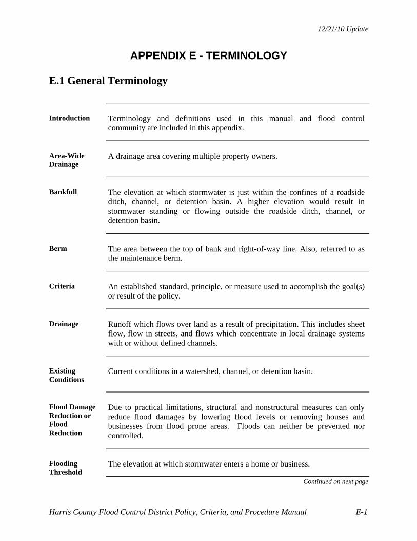
12/21/10 Update
Harris County Flood Control District Policy, Criteria, and Procedure Manual E-1
APPENDIX E - TERMINOLOGY
E.1 General Terminology
Introduction Terminology and definitions used in this manual and flood control
community are included in this appendix.
Area-Wide Drainage
A drainage area covering multiple property owners.
Bankfull The elevation at which stormwater is just within the confines of a roadside
ditch, channel, or detention basin. A higher elevation would result in stormwater standing or flowing outside the roadside ditch, channel, or detention basin.
Berm The area between the top of bank and right-of-way line. Also, referred to as
the maintenance berm.
Criteria An established standard, principle, or measure used to accomplish the goal(s)
or result of the policy.
Drainage Runoff which flows over land as a result of precipitation. This includes sheet
flow, flow in streets, and flows which concentrate in local drainage systems with or without defined channels.
Existing Conditions
Current conditions in a watershed, channel, or detention basin.
Flood Damage Reduction or Flood Reduction
Due to practical limitations, structural and nonstructural measures can only reduce flood damages by lowering flood levels or removing houses and businesses from flood prone areas. Floods can neither be prevented nor controlled.
Flooding Threshold
The elevation at which stormwater enters a home or business.
Continued on next page

12/21/10 Update
Harris County Flood Control District Policy, Criteria, and Procedure Manual E-2
E.1 General Terminology, Continued
Interim Conditions
Conditions in a watershed, channel, or detention basin between existing and ultimate. Typically, a design condition with the proposed development or project in place.
Master Planned Project
Master planned projects:
Have a channel and/or detention facilities that serve multiple tracts or properties
Are constructed in three or more phases
Conduct a full hydrological and hydraulic analysis utilizing the Watershed Modeling Method (see Section 3.4, Watershed Modeling Method), and
Document the analysis results, proposed drainage plan, and phasing plan in a drainage plan report.
New Development
Any increase in impervious cover or change in land condition that affects the amount or rate of runoff from a property. New development acreage as used to calculate detention volume or impact fees is determined using the entire property, not just the area of impervious cover or drainage improvement, unless a substantial portion is left undisturbed.
Also, see “Regulations of Harris County, Texas for Flood Plain Management”.
Owner The individual or entity who is responsible for the design and construction of
the project submitted to the HCFCD for review, approval, and acceptance.
Policy A written strategy intended to obtain a goal or result in a prudent, practical,
and expedient manner. Policies are adopted by Harris County Commissioners Court.
Pre-Development or Pre-Project Conditions
Conditions in a watershed, channel, or detention basin prior to construction of a proposed development or project.
Continued on next page

12/21/10 Update
Harris County Flood Control District Policy, Criteria, and Procedure Manual E-3
E.1 General Terminology, Continued
System Capacity
The amount of stormwater runoff a drainage system can carry or store before the flooding threshold is reached. Measurement is usually flow rate in cubic feet per second. The drainage system can consist of only conveyance components such as enclosed conduits and/or open channels, or conveyance components and stormwater detention basins.
Ultimate Conditions
100% development conditions in a watershed.
Watershed Diversion
A watershed diversion occurs when open channels and detention basins divert stormwater from one main channel watershed to another, such as from the Willow Creek (M100-00-00) watershed to the Spring Creek (J100-00-00) watershed.

12/21/10 Update
Harris County Flood Control District Policy, Criteria, and Procedure Manual E-4
E.2 Channel Terminology
Bypass A partial flow realignment that leaves and enters on the same channel.
Channel Modification or Conveyance Improvement
Activities in a channel such as widening, deepening, enlarging, straightening, or smoothing that increases channel conveyance.
The term channel improvement is not recommended because improvement depends on one’s perspective.
Channel Rehabilitation
Re-establishing the design cross-section or conveyance in a defined reach.
Diversion Interception of a partial or full flow that takes the water to a different channel
across a watershed or subarea divide.
Interconnect A channel that connects two different channels and allows flow in either
direction.
Main Channel A principle stream, creek, or bayou.
Examples: Cypress Creek (K100-00-00), Brays Bayou (D100-00-00), and Hunting Bayou (H100-00-00).
Main Stem See definition in Appendix F.
Maintenance Project
Repair or rehabilitation of a specific problem or site.
Primary Tributary
A stream, creek, or bayou that flows into a main channel.
Examples: Faulkey Gully (K142-00-00), Halls Bayou (P118-00-00), and Berry Bayou (C106-00-00).
Secondary Tributary
A stream, creek, or bayou that flows into a primary tributary.
Examples: K142-07-00, P118-09-00, and C106-03-08.
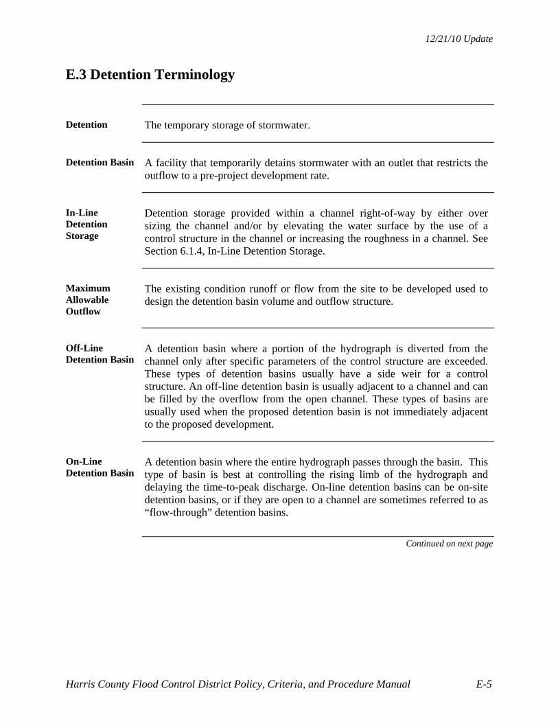
12/21/10 Update
Harris County Flood Control District Policy, Criteria, and Procedure Manual E-5
E.3 Detention Terminology
Detention The temporary storage of stormwater.
Detention Basin A facility that temporarily detains stormwater with an outlet that restricts the
outflow to a pre-project development rate.
In-Line Detention Storage
Detention storage provided within a channel right-of-way by either over sizing the channel and/or by elevating the water surface by the use of a control structure in the channel or increasing the roughness in a channel. See Section 6.1.4, In-Line Detention Storage.
Maximum Allowable Outflow
The existing condition runoff or flow from the site to be developed used to design the detention basin volume and outflow structure.
Off-Line Detention Basin
A detention basin where a portion of the hydrograph is diverted from the channel only after specific parameters of the control structure are exceeded. These types of detention basins usually have a side weir for a control structure. An off-line detention basin is usually adjacent to a channel and can be filled by the overflow from the open channel. These types of basins are usually used when the proposed detention basin is not immediately adjacent to the proposed development.
On-Line Detention Basin
A detention basin where the entire hydrograph passes through the basin. This type of basin is best at controlling the rising limb of the hydrograph and delaying the time-to-peak discharge. On-line detention basins can be on-site detention basins, or if they are open to a channel are sometimes referred to as “flow-through” detention basins.
Continued on next page

12/21/10 Update
Harris County Flood Control District Policy, Criteria, and Procedure Manual E-6
E.3 Detention Terminology, Continued
On-Site Detention Basin
A detention basin built specifically for a new land development that receives runoff only from the new development. It can be a private or public detention basin. These types of basins are within the proposed development, accept all the runoff from the development, and are usually restricted at the outfall prior to entering the receiving channel.
Regional Detention Basin
A stormwater detention basin that is part of a HCFCD regional plan or flood damage reduction project, is located on a main channel or primary tributary, is within a HCFCD right-of-way, and is managed by HCFCD.
Retention The storage of stormwater for an indefinite period of time. A retention basin
does not have an outlet structure.
Tailwater The water surface elevation in the outfall channel at the outflow structure
which varies with time. The tailwater affects both the outflow structure design and the stage-outflow relationship of the detention basin.

12/21/10 Update
Harris County Flood Control District Policy, Criteria, and Procedure Manual E-7
E.4 Project Review Terminology
Construction Drawing
Drawings prepared by a licensed professional civil engineer used to construct a proposed development or roadway, drainage facilities, and features in a HCFCD maintained facility.
Drainage Plan Plan for an existing or proposed development or roadway showing the
topography, stormwater flow patterns, internal drainage system, outfall channels, detention facilities, offsite impacts, and other applicable stormwater management components.
Express Review Sheet
A sheet required in the construction drawings by Harris County and HCFCD that includes prescribed information for the owner’s engineer to provide to facilitate review and signatures.
Mark-Ups Construction drawings or reports that have comments from a HCFCD review
written on them.
Note: Mark-ups must be returned with the next submittal. The HCFCD does not keep copies of mark-ups.
Prints Paper copies made from original construction drawings.
Owner’s Engineer
The civil engineer representing the owner of the project.
Record Drawing
A construction drawing that indicates how the project was actually constructed, including changes made during construction. The seal and signature of a Texas Licensed Professional Engineer is required.
Note: Field surveys, laboratory tests, frequency of inspection, and other related activities are at the discretion of the Engineer sealing the record drawings.

12/21/10 Update
Harris County Flood Control District Policy, Criteria, and Procedure Manual E-8
E.5 Technical Terminology
1% Chance Exceedance Probability
An event that has a 1% chance of being equaled or exceeded in any one year at a given location. This can refer to both rainfall and flood events. It is shortened to 1% exceedance in this manual.
Below is a table showing the comparison of the more commonly used exceedance probabilities and frequencies:
FREQUENCY EXCEEDANCE PROBABILITY
500-year 0.2% chance 100-year 1% chance 50-year 2% chance 25-year 4% chance 10-year 10% chance 5-year 20% chance 3-year 33% chance 2-year 50% chance
Base Flood Elevation
A FEMA term that means the water surface elevation at a location produced by the 1% exceedance probability flood event.
Normal Water Surface
The water surface in a channel the majority of the time produced by normal flow when there is no direct rainfall runoff or drought conditions.
The normal water surface is usually at or near the vegetation line. Secondary tributaries usually have a normal water surface at or near the channel bottom. Main channels and primary tributaries usually have normal water surfaces 1’- 3’ above the channel flowline, excluding areas of erosion or deposition.

12/21/10 Update
Harris County Flood Control District Policy, Criteria, and Procedure Manual E-9
E.6 Right-of-Way Terminology
Conveyance Transfer of a real property interest from one party to another in fee simple or
easement. The conveyance can be a sale or a donation.
A written instrument must be used and it must be reviewed and accepted by HCFCD. Conveyances can create HCFCD fee properties or HCFCD easements.
Dedication The act of a property owner who sets aside a portion of his property for the
use of the public for a specific purpose. A dedication may be accomplished by plat or separate instrument and always creates an easement.
Dedications create public drainage easements that HCFCD can use to maintain open channel and detention facilities.
Easement A limited interest in real property for a specific purpose, usually designated in
the granting instrument or plat. Another entity or individual has fee title to the property.
Fee or Fee Simple
Full ownership of real property by an individual or entity.
HCFCD Right-of-Way
Implies HCFCD has property rights to manage a HCFCD facility. It includes:
1. Property owned in fee by HCFCD
2. HCFCD drainage or flooding easement conveyed to and accepted by HCFCD through Commissioners Court
3. A public drainage easement accepted by HCFCD through Commissioners Court into the HCFCD Stormwater Management System
4. A channel’s bed and banks as defined in the HCFCD’s enabling legislation.
Right-of-Way An interest in real property, either in fee or easement.
Ultimate Right-of-Way
The maximum right-of-way necessary to construct and maintain a channel or detention facility, assuming full upstream development, under stormwater management policies in effect for that watershed.
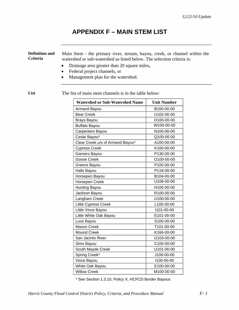
12/21/10 Update
Harris County Flood Control District Policy, Criteria, and Procedure Manual F- 1
APPENDIX F – MAIN STEM LIST
Definition and Criteria
Main Stem - the primary river, stream, bayou, creek, or channel within the watershed or sub-watershed as listed below. The selection criteria is:
Drainage area greater than 20 square miles, Federal project channels, or Management plan for the watershed.
List The list of main stem channels is in the table below:
Watershed or Sub-Watershed Name Unit Number
Armand Bayou B100-00-00
Bear Creek U102-00-00
Brays Bayou D100-00-00
Buffalo Bayou W100-00-00
Carpenters Bayou N100-00-00
Cedar Bayou* Q100-00-00
Clear Creek u/s of Armand Bayou* A100-00-00
Cypress Creek K100-00-00
Garners Bayou P130-00-00
Goose Creek O100-00-00
Greens Bayou P100-00-00
Halls Bayou P118-00-00
Horsepen Bayou B104-00-00
Horsepen Creek U106-00-00
Hunting Bayou H100-00-00
Jackson Bayou R100-00-00
Langham Creek U100-00-00
Little Cypress Creek L100-00-00
Little Vince Bayou I101-00-00
Little White Oak Bayou E101-00-00
Luce Bayou S100-00-00
Mason Creek T101-00-00
Mound Creek K166-00-00
San Jacinto River G103-00-00
Sims Bayou C100-00-00
South Mayde Creek U101-00-00
Spring Creek* J100-00-00
Vince Bayou I100-00-00
White Oak Bayou E100-00-00
Willow Creek M100-00-00
* See Section 1.3.10, Policy X, HCFCD Border Bayous

12/21/10 Update
Harris County Flood Control District Policy and Criteria Manual G-1
APPENDIX G - REFERENCES
Introduction
This appendix provides the source of documents referenced in this manual.
HCFCD H & H Guidance Manual
“Hydrology and Hydraulics Guidance Manual”, December 2009, Harris County Flood Control District
http://www.hcfcd.org/hhmanual.html
Harris County Regulations
"Regulations of Harris County, Texas for the Approval and Acceptance of Infrastructure"
"Regulations of Harris County, Texas for Flood Plain Management"
“Rules of Harris County and the Harris County Flood Control District for the Construction of Facilities within Harris County Flood Control District Rights of Way”
"Regulations of Harris County, Texas for Storm Water Quality Management"
http://hcpid.org/permits/comp_regs.html
"Harris County Public Infrastructure Department Engineering Division-
Permit Office Storm Water Quality Guidance Document for New Development/Redevelopment Projects"
http://hcpid.org/permits/docs/SWQ_manual_residential_devel.pdf
High Tide Information
One possible sources is:
http://tidesandcurrents.noaa.gov/tide_pred.html