e3125_telecommunication_unit1.doc
DESCRIPTION
TELEKOMUNIKASITRANSCRIPT
E3125/1/1INTRODUCTION TO TELEPHONY SYSTEM
INTRODUCTION TO TELEPHONY SYSTEM
OBJECTIVES
General Objective : To understand the concept of telephony system, the types of the
telephone exchanges and the switching concept.
Specific Objectives : At the end of the unit you will be able to:
explain the need of the telephony networking system.
sketch the telephone network for local exchange and telephone
network hierarchy.
define PSTN and MTX telephone exchange.
explain switching concept including matrix switching, step by
step, common controller and SPC.
draw the SPC block diagram and to understand the advantages
and disadvantages of the system.
UNIT 1
E3125/1/2INTRODUCTION TO TELEPHONY SYSTEM
1.0 Introduction
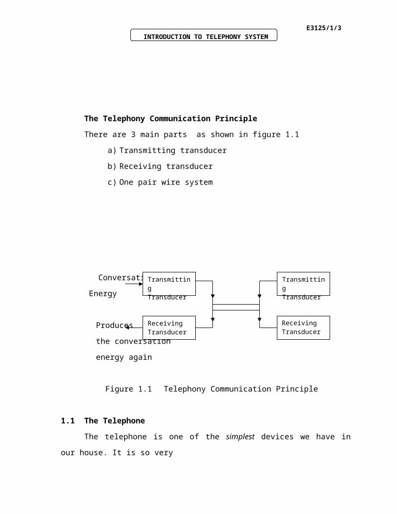
The Telephony Communication Principle
There are 3 main parts as shown in figure 1.1
a) Transmitting transducer
b) Receiving transducer
c) One pair wire system
INPUTINPUT
We use telephony system in our everyday life. The equipment involves telephone sets at home, the internet, e-mails, our mobile phones and telefaxes. Telephony system makes our life much more easier.
E3125/1/3INTRODUCTION TO TELEPHONY SYSTEM
Conversation
Energy
Produces
the conversation
energy again
Figure 1.1 Telephony Communication Principle
1.1 The Telephone
The telephone is one of the simplest devices we have in our house. It is so very
simple because the telephone connection to our house has not changed in
nearly a century.
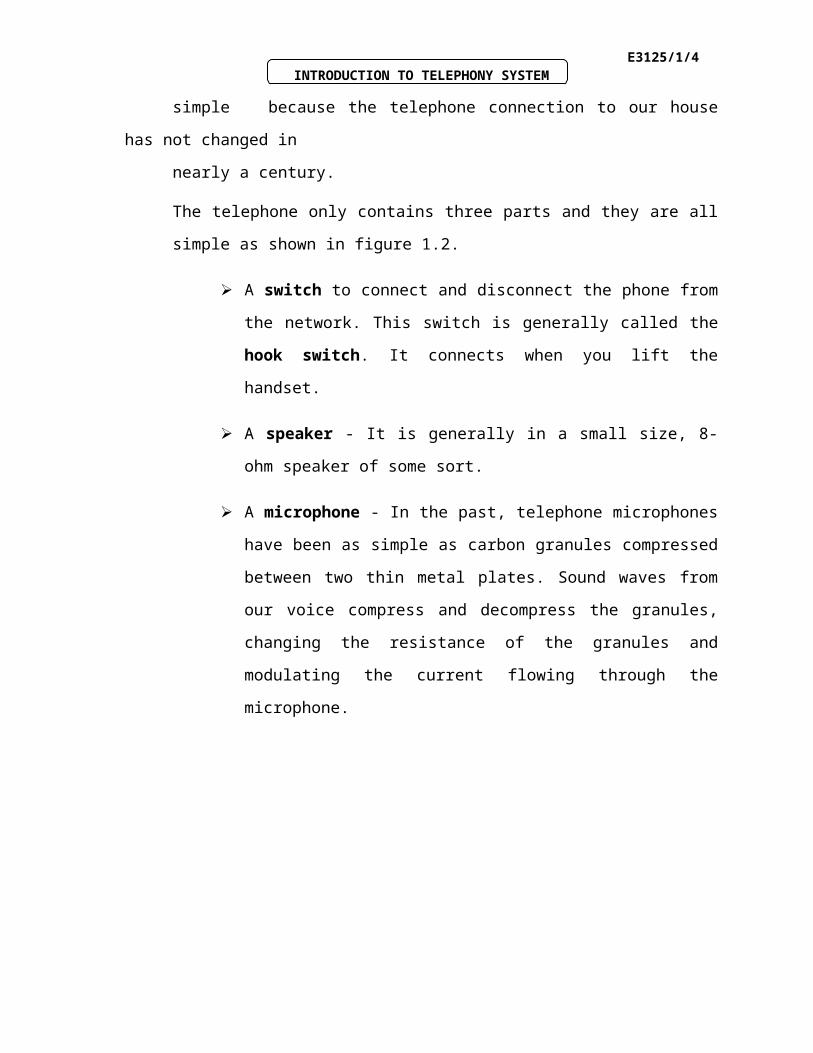
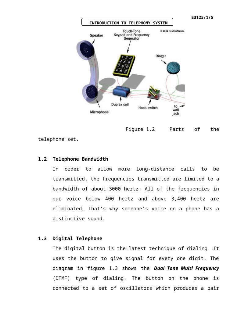
The telephone only contains three parts and they are all simple as shown in figure
1.2.
A switch to connect and disconnect the phone from the network. This
switch is generally called the hook switch. It connects when you lift the
handset.
A speaker - It is generally in a small size, 8-ohm speaker of some sort.
A microphone - In the past, telephone microphones have been as simple
as carbon granules compressed between two thin metal plates. Sound
waves from our voice compress and decompress the granules, changing
the resistance of the granules and modulating the current flowing through
the microphone.
TransmittingTransducer
ReceivingTransducer
ReceivingTransducer
Transmitting Transducer
E3125/1/4INTRODUCTION TO TELEPHONY SYSTEM
Figure 1.2 Parts of the telephone set.
1.2 Telephone Bandwidth
In order to allow more long-distance calls to be transmitted, the frequencies
transmitted are limited to a bandwidth of about 3000 hertz. All of the frequencies in
our voice below 400 hertz and above 3,400 hertz are eliminated. That's why
someone's voice on a phone has a distinctive sound.
1.3 Digital Telephone
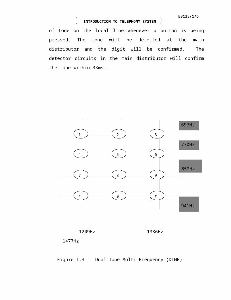
The digital button is the latest technique of dialing. It uses the button to give signal
for every one digit. The diagram in figure 1.3 shows the Dual Tone Multi
Frequency (DTMF) type of dialing. The button on the phone is connected to a set of
oscillators which produces a pair of tone on the local line whenever a button is being
pressed. The tone will be detected at the main distributor and the digit will be
confirmed. The detector circuits in the main distributor will confirm the tone within
33ms.
E3125/1/5INTRODUCTION TO TELEPHONY SYSTEM
1209Hz 1336Hz 1477Hz
Figure 1.3 Dual Tone Multi Frequency (DTMF)
1.3.1 Progress Tones
The various types of tones generated by the exchange to guide the users are :
Dial Tone (DT). This is a 33 c/s continuous note and is applied to the line
after the subscriber has lifted his handset and the switching equipment has
allocated him an available outlet for this call to proceed. There would have
been a physical limit on the number of calls an exchange could handle so if
all equipment was already in use, the subscriber would not get a dial tone.
Busy Tone (BT). A higher pitched note of 400 c/s interrupts to give a
cadence of 0.75 seconds on, 0.75 seconds off. Busy tone indicates either that
the called subscriber is already off-hook (busy) or that the route to the called
subscriber is congested. In later systems, a slightly different cadence was
introduced in order to distinguish between these two scenarios. A busy tone
is made up of a 480-hertz and a 620-hertz tone, with a cycle of one and a half
second on and one and a half second off.
1
4
7 8 9
5 6
32
#0*
697Hz
770Hz
852Hz
941Hz
E3125/1/6INTRODUCTION TO TELEPHONY SYSTEM
Number Unobtainable Tone (NUT). Identical pitch to the busy tone but
continuous. This tone is used to indicate that a number is out of service,
faulty or that a spare line has been dialed.
Ring Tone (RT). A tone of 133c/s which interrupts in the same cadence as
the ring current which rings the telephone bell at the called party's end : 0.4
seconds on, 0.2 seconds off.
E3125/1/7INTRODUCTION TO TELEPHONY SYSTEM
Example 1.1
Do you know the human’s voice frequency ?
Solution to Example 1.1
The answer is between 300 – 3400 Hz.
Telephony System surely makes my job easier.Yahoo !!!
E3125/1/8INTRODUCTION TO TELEPHONY SYSTEM
Activity 1A
TEST OUR UNDERSTANDING BEFORE YOU CONTINUE WITH THE
NEXT INPUT…!
1.1 State THREE main parts of the telephone system and draw the block
diagram.
1.2 List and explain FOUR types of the telephone supervisory (progress) tones .
Telephony system makes the world becomes smaller through the usage of the internet. This won’t be achieved without the advancement in telephony technology.
E3125/1/9INTRODUCTION TO TELEPHONY SYSTEM
Feedback To Activity 1A
1.1 There are 3 main parts as shown in figure 1.1
a) Transmitting transducer
b) Receiving transducer
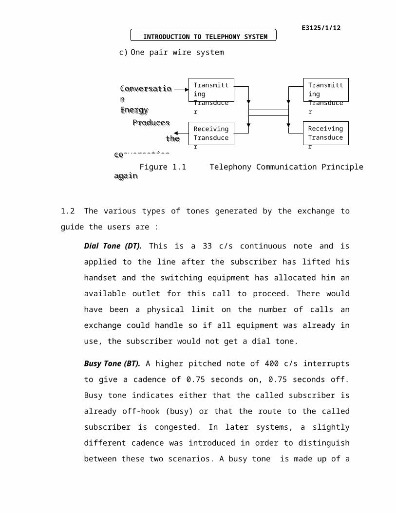
c) One pair wire system
1.2 The various types of tones generated by the exchange to guide the users are :
Dial Tone (DT). This is a 33 c/s continuous note and is applied to the line after the
subscriber has lifted his handset and the switching equipment has allocated him an
available outlet for this call to proceed. There would have been a physical limit on
the number of calls an exchange could handle so if all equipment was already in use,
the subscriber would not get a dial tone.
Busy Tone (BT). A higher pitched note of 400 c/s interrupts to give a cadence of
0.75 seconds on, 0.75 seconds off. Busy tone indicates either that the called
TransmittingTransducer
ReceivingTransducer
ReceivingTransducer
Transmitting Transducer
Produces
the conversation energy again
Produces
the conversation energy again
Conversation EnergyConversation Energy
Figure 1.1 Telephony Communication Principle
E3125/1/10INTRODUCTION TO TELEPHONY SYSTEM
subscriber is already off-hook (busy) or that the route to the called subscriber is
congested. In later systems, a slightly different cadence was introduced in order to
distinguish between these two scenarios. A busy tone is made up of a 480-hertz and
a 620-hertz tone, with a cycle of one and a half second on and one and a half second
off.
Number Unobtainable Tone (NUT). Identical pitch to the busy tone but continuous.
This tone is used to indicate that a number is out of service, faulty or that a spare line
has been dialed.
Ring Tone (RT). A tone of 133c/s which interrupts in the same cadence as the ring
current which rings the telephone bell at the called party's end : 0.4 seconds on, 0.2
seconds off.
E3125/1/11INTRODUCTION TO TELEPHONY SYSTEM
1.4 The Telephone Exchange
The telephone exchange is the place where all the telephone lines are connected so
that the communication using the human’s voice could be achieved. The device in
the exchange will act as a switch which contacts whenever it is directed.
1.4.1 The Telephone Connection Between Two Subscribers.
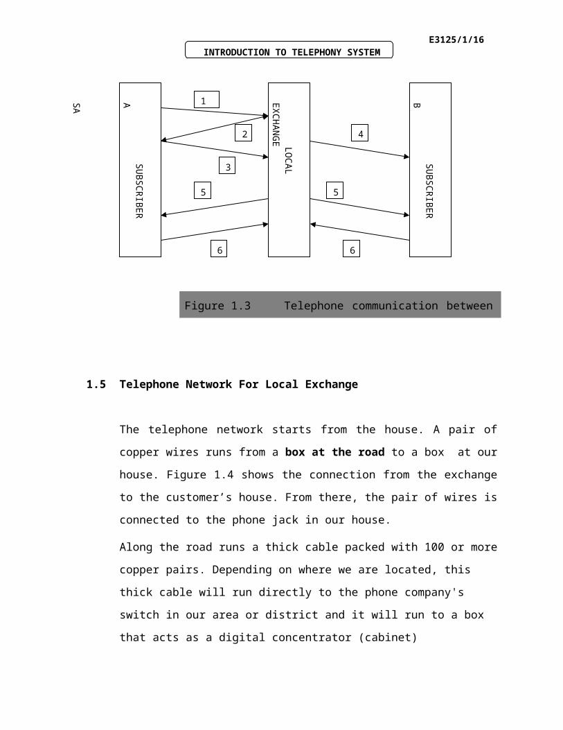
The connection process is shown in figure 1.3.
1. When Subscriber A picks up the telephone set, Local Exchange will
detect a call request signal from Subscriber A..
2. Local Exchange will send a dial tone to Subscriber A.
3. Subscriber A starts to dial the numbers. The numbers received will be
tested by the Local Exchange.
4. If the numbers are valid, Local Exchange will test whether the line is
available or not.
5. If the line is available, Local Exchange will do the connection. Local
Exchange will send a ringing tone to Subscriber A and the signal to
ring the Subscriber B’s telephone. Subscriber B will pick up the
telephone set, thus making the dialing tone stop.
INPUTINPUT
E3125/1/12INTRODUCTION TO TELEPHONY SYSTEM
6. If either one of the subscribers hangs up the phone , communication
will be disconnected and the Local Exchange will clear the line.
1.5 Telephone Network For Local Exchange
The telephone network starts from the house. A pair of copper wires runs from a box
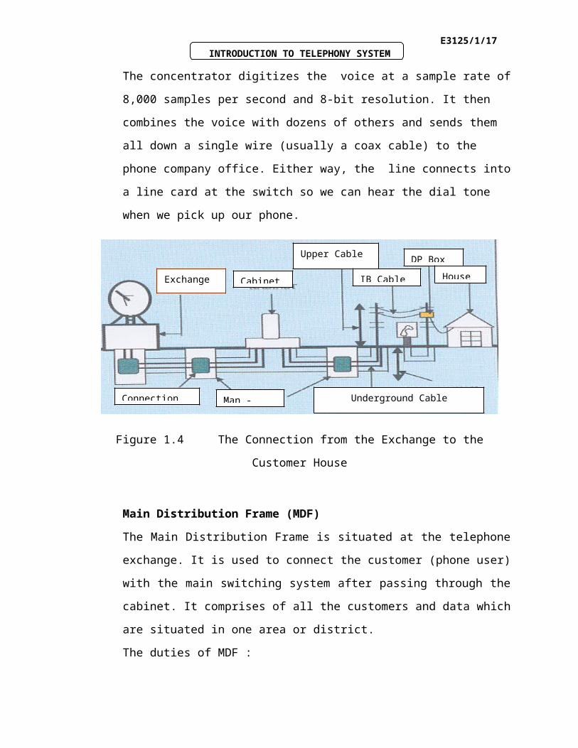
at the road to a box at our house. Figure 1.4 shows the connection from the
exchange to the customer’s house. From there, the pair of wires is connected to the
phone jack in our house.
Along the road runs a thick cable packed with 100 or more copper pairs. Depending
on where we are located, this thick cable will run directly to the phone company's
switch in our area or district and it will run to a box that acts as a digital
concentrator (cabinet)
The concentrator digitizes the voice at a sample rate of 8,000 samples per second
and 8-bit resolution. It then combines the voice with dozens of others and sends them
1
2
3
4
5 5
6 6
SU
BS
CR
IBE
R A
SA
SU
BS
CR
IBE
R B
LO
CA
L E
XC
HA
NG
E
Figure 1.3 Telephone communication between subscribers
E3125/1/13INTRODUCTION TO TELEPHONY SYSTEM
all down a single wire (usually a coax cable) to the phone company office. Either
way, the line connects into a line card at the switch so we can hear the dial tone
when we pick up our phone.
Figure 1.4 The Connection from the Exchange to the Customer House
Main Distribution Frame (MDF)
The Main Distribution Frame is situated at the telephone exchange. It is used to
connect the customer (phone user) with the main switching system after passing
through the cabinet. It comprises of all the customers and data which are situated in
one area or district.
The duties of MDF :
a) To test the phone line.
b) To execute the jumper process.
c) To check the problem phone line.
d) To cut the phone line manually.
e) To connect the phone line manually.
Cabinet
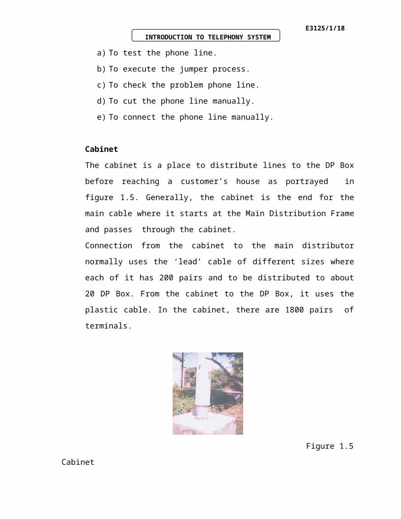
The cabinet is a place to distribute lines to the DP Box before reaching a customer’s
house as portrayed in figure 1.5. Generally, the cabinet is the end for the main cable
where it starts at the Main Distribution Frame and passes through the cabinet.
Exchange Cabinet
Upper Cable
IB Cable
DP Box
House
Connection Underground CableMan - hole
E3125/1/14INTRODUCTION TO TELEPHONY SYSTEM
Connection from the cabinet to the main distributor normally uses the ‘lead’ cable of
different sizes where each of it has 200 pairs and to be distributed to about 20 DP
Box. From the cabinet to the DP Box, it uses the plastic cable. In the cabinet, there
are 1800 pairs of terminals.
Figure 1.5 Cabinet
The Cabinet’s functions are as follows :
a. To save the usage of cable and replacing cable would be easier.
b. To avoid the joint to be opened and this would save cost and time.
c. To act as a place to perform maintenance checking.
d. To upgrade the arrangement of lines.
Distribution Point Box (DP)
The DP Box’s function is to make maintenance work and underground cabling
easier. Usually, the DP Box has 10 pairs but only 8 pairs are used and the others
kept for testing work from DP Box to the main distributor.
Upper Cable
The upper cable is used to make connection with the customers using the DP Box.
The two wire cable normally is used.
E3125/1/15INTRODUCTION TO TELEPHONY SYSTEM
Underground Cable
The underground cable is connected to the cabinet from the DP through man-holes.
The underground cable will end at the telephone exchange.
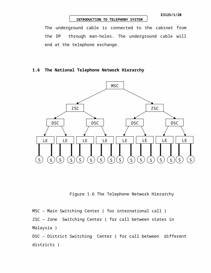
1.6 The National Telephone Network Hierarchy
Figure 1.6 The Telephone Network Hierarchy
MSC – Main Switching Center ( for international call )
ZSC – Zone Switching Center ( for call between states in Malaysia )
DSC – District Switching Center ( for call between different districts )
LE – Local Exchange
S – Phone User / Subscriber
The National Telephone Network Hierarchy is the network that links all the exchanges in
one country.
MSC
ZSC ZSC
DSC DSC DSC DSC
LE LE LE LELE LE LELE
S S S S S S S S S S S S S S S S
E3125/1/16INTRODUCTION TO TELEPHONY SYSTEM
Example 1.2
What does DTMF stand for ?
Solution to Example 1.2
DTMF (Dual-tone Multi frequency) is a type of dialing system which uses a pair of
audio tone to create signals representing the numbers to be dialed. It is also named as
Touch Tone.
E3125/1/17INTRODUCTION TO TELEPHONY SYSTEM
Activity 1B
TEST OUR UNDERSTANDING BEFORE YOU CONTINUE WITH THE
NEXT INPUT…!
1.3 Sketch and explain the connection from the exchange to the customer ‘s
house.
1.4 Describe with the aid of a suitable diagram the route of your call if you want
to make a call from your polytechnic to another polytechnic nearest to you.
E3125/1/18INTRODUCTION TO TELEPHONY SYSTEM
Feedback To Activity 1B
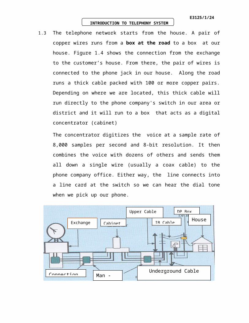
1.3 The telephone network starts from the house. A pair of copper wires runs from a box
at the road to a box at our house. Figure 1.4 shows the connection from the
exchange to the customer’s house. From there, the pair of wires is connected to the
phone jack in our house. Along the road runs a thick cable packed with 100 or more
copper pairs. Depending on where we are located, this thick cable will run directly to
the phone company's switch in our area or district and it will run to a box that acts as
a digital concentrator (cabinet)
The concentrator digitizes the voice at a sample rate of 8,000 samples per second
and 8-bit resolution. It then combines the voice with dozens of others and sends them
all down a single wire (usually a coax cable) to the phone company office. Either
way, the line connects into a line card at the switch so we can hear the dial tone
when we pick up our phone.
Figure 1.4 The Connection from the Exchange to the Customer House
Exchange Cabinet
Upper Cable
IB Cable
DP Box
House
ConnectionUnderground Cable
Man - hole
E3125/1/19INTRODUCTION TO TELEPHONY SYSTEM
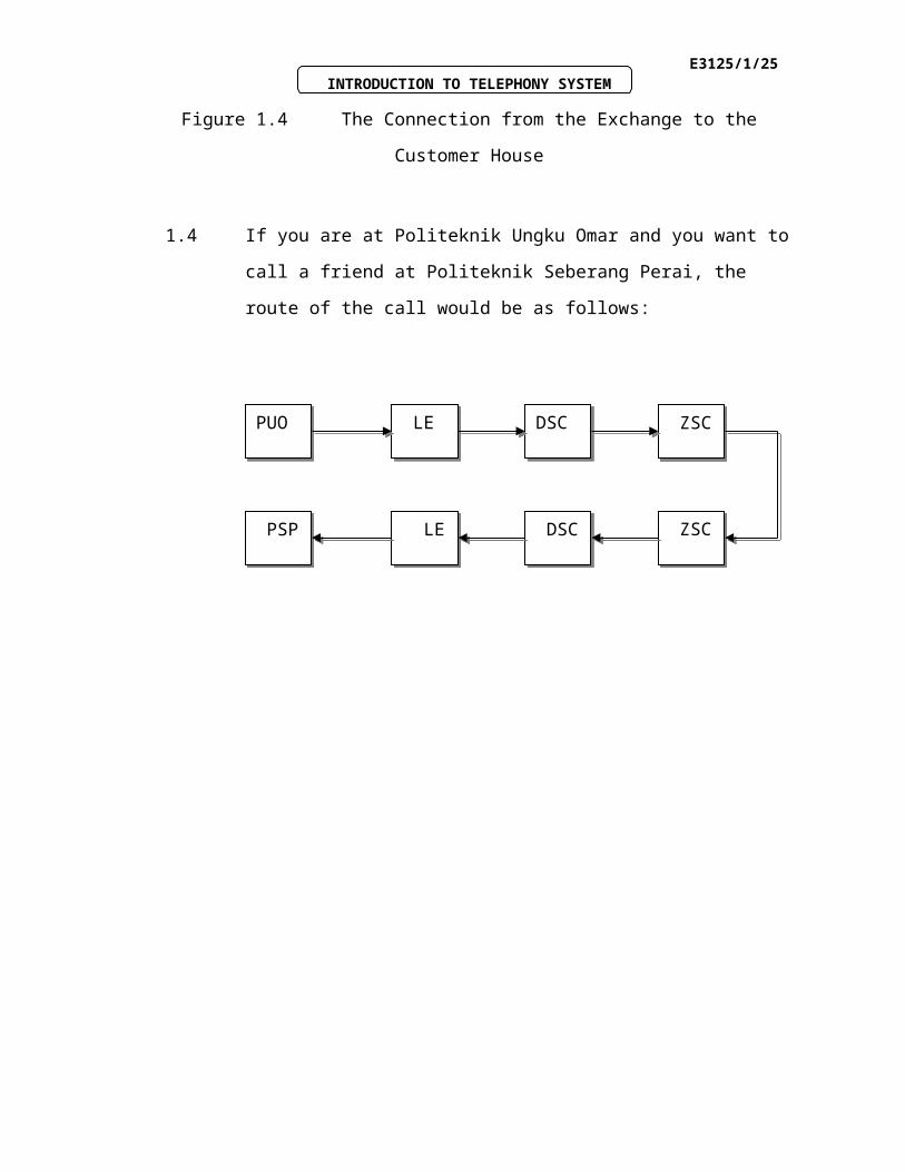
1.4 If you are at Politeknik Ungku Omar and you want to call a friend at
Politeknik Seberang Perai, the route of the call would be as follows:
PUOPUO LE LE DSCDSC ZSC ZSC
PSP PSP LE LE DSC DSC ZSC ZSC
E3125/1/20INTRODUCTION TO TELEPHONY SYSTEM
1.7 Switching Concept
Switch is used to provide a path for the call. The switch performs three main
functions to process a call:
a) To identify the subscriber’s location
b) To set up the communication path
c) To supervise the call
By using the jack position, the customers occupying the switchboard can be easily
identified. With the introduction of electromechanical switches, customers are given
telephone numbers. The customer's cable pair is terminated and cross-connected to
the office equipment at the main distributing frame. Office equipment terminated on
the MDF represents a physical location in the switch and a specific telephone
number.
INPUTINPUT
Do you wonder how the telephone exchange works?
E3125/1/21INTRODUCTION TO TELEPHONY SYSTEM
1.8 Public Switching Telephone Network (PSTN)
Public Switching Telephone Network (PSTN) is the world's collection of
interconnected voice-oriented public telephone networks. The PSTN consists of a
digital backbone of switched circuits together with the analog local loop wiring still
found in many residences. The PSTN provides the most popular basis for creating
wide area networks (WANs) through both leased lines and dial-up lines between
local and remote networks. PSTN is often used in wide area networking and because
of its ubiquitous nature local loop connections exist almost everywhere in the world.
In relation to the Internet, the PSTN actually furnishes much of the Internet's long-
distance infrastructure. Because Internet service providers ISPs pay the long-distance
providers for access to their infrastructure and share the circuits among many users
through packet-switching, Internet users avoid having to pay usage tolls to anyone
other than their ISPs.
The process of signal transmission needs switching network such as concentrator,
distributor, expander and multiplexer. Combination of all these networks will form a
complete PSTN.
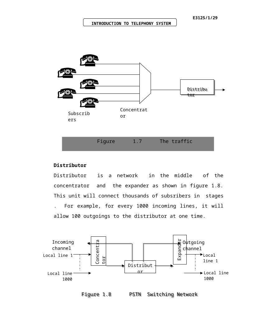
Concentrator
Figure 1.7 shows the concentrator concept in PSTN network.The concentrator unit is
controlled directly by the local exchange. All the subscribers can be connected
simultaneously at different channels. This will reduce the cost of installation and
maintenance.
E3125/1/22INTRODUCTION TO TELEPHONY SYSTEM
Distributor
Distributor is a network in the middle of the concentrator and the expander as
shown in figure 1.8. This unit will connect thousands of subsribers in stages . For
example, for every 1000 incoming lines, it will allow 100 outgoings to the distributor
at one time.
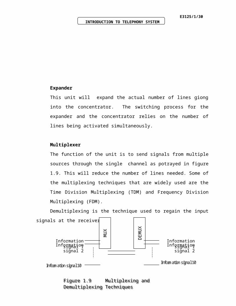
Expander
Concentrator Subscribers
DistributorDistributor
Figure 1.7 The traffic concentration in PSTN network.
Local line 1
Local line 1000Local line 1000
Con
cent
rato
r
Distributor
Exp
ande
r
Local line 1
Outgoing channelIncoming channel
Figure 1.8 PSTN Switching NetworkFigure 1.8 PSTN Switching Network
E3125/1/23INTRODUCTION TO TELEPHONY SYSTEM
This unit will expand the actual number of lines giong into the concentrator. The
switching process for the expander and the concentrator relies on the number of lines
being activated simultaneously.
Multiplexer
The function of the unit is to send signals from multiple sources through the single
channel as potrayed in figure 1.9. This will reduce the number of lines needed. Some
of the multiplexing techniques that are widely used are the Time Division
Multiplexing (TDM) and Frequency Division Multiplexing (FDM).
Demultiplexing is the technique used to regain the input signals at the receiver.
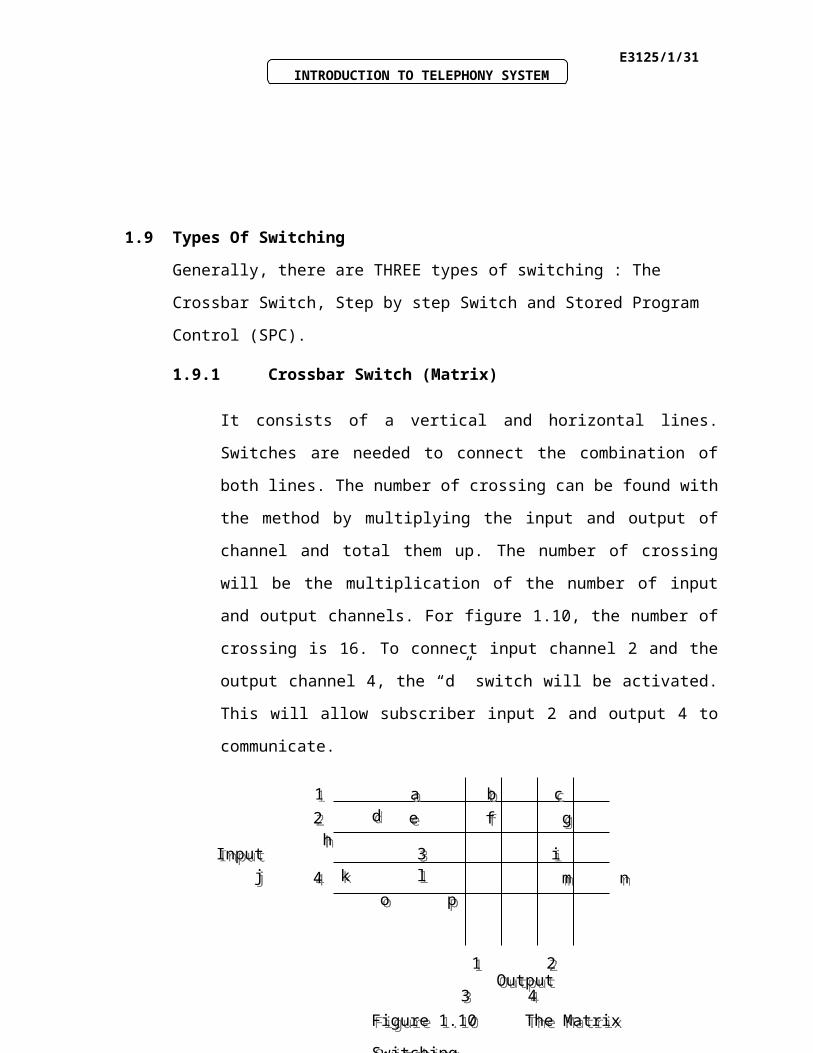
1.9 Types Of Switching
Generally, there are THREE types of switching : The Crossbar Switch, Step by step
Switch and Stored Program Control (SPC).
1.9.1 Crossbar Switch (Matrix)
It consists of a vertical and horizontal lines. Switches are needed to connect
the combination of both lines. The number of crossing can be found with the
method by multiplying the input and output of channel and total them up. The
number of crossing will be the multiplication of the number of input and
output channels. For figure 1.10, the number of crossing is 16. To connect
input channel 2 and the output channel 4, the “d” switch will be activated.
This will allow subscriber input 2 and output 4 to communicate.
MU
X
Information signal 1Information signal 2
Information signal 10 D
EM
UX
Information signal 1Information signal 2
Information signal 10
Figure 1.9 Multiplexing and Demultiplexing TechniquesFigure 1.9 Multiplexing and Demultiplexing Techniques
E3125/1/24INTRODUCTION TO TELEPHONY SYSTEM
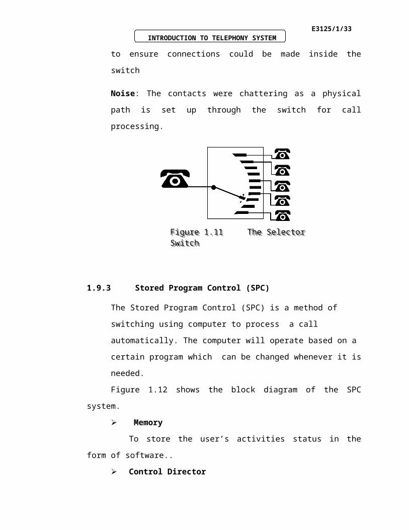
1.9.2 Step-by-Step Switch
Almon Strowger invented the first "automatic" switch in 1890. It was the step
by step electromechanical switch. It was first installed in 1892. The name
Step-by-Step came from the way the path is set up step-by step as each digit
was dialed as shown in figure 1.11. The fundamental process was that
telephone calls progressed through switches in steps, each step being made in
response to the dialing of a digit.
The problems of the Step-by-Step switch were:
Power : Required a large amount of electricity to move switch components
for call processing
Floor Space: Major switch components were made of brass, copper and
magnets which were so heavy that required steel reinforcement in the floors
where they were installed
High Maintenance: The large number of moving parts in this switch
required constant dusting and oiling to ensure connections could be made
inside the switch
Noise: The contacts were chattering as a physical path is set up through the
switch for call processing.
1 a b c d 1 a b c d
2 e f g h2 e f g h
Input 3 i j k lInput 3 i j k l
4 m n o p4 m n o p
1 2 3 4 1 2 3 4Output Output
Figure 1.10 The Matrix SwitchingFigure 1.10 The Matrix Switching
E3125/1/25INTRODUCTION TO TELEPHONY SYSTEM
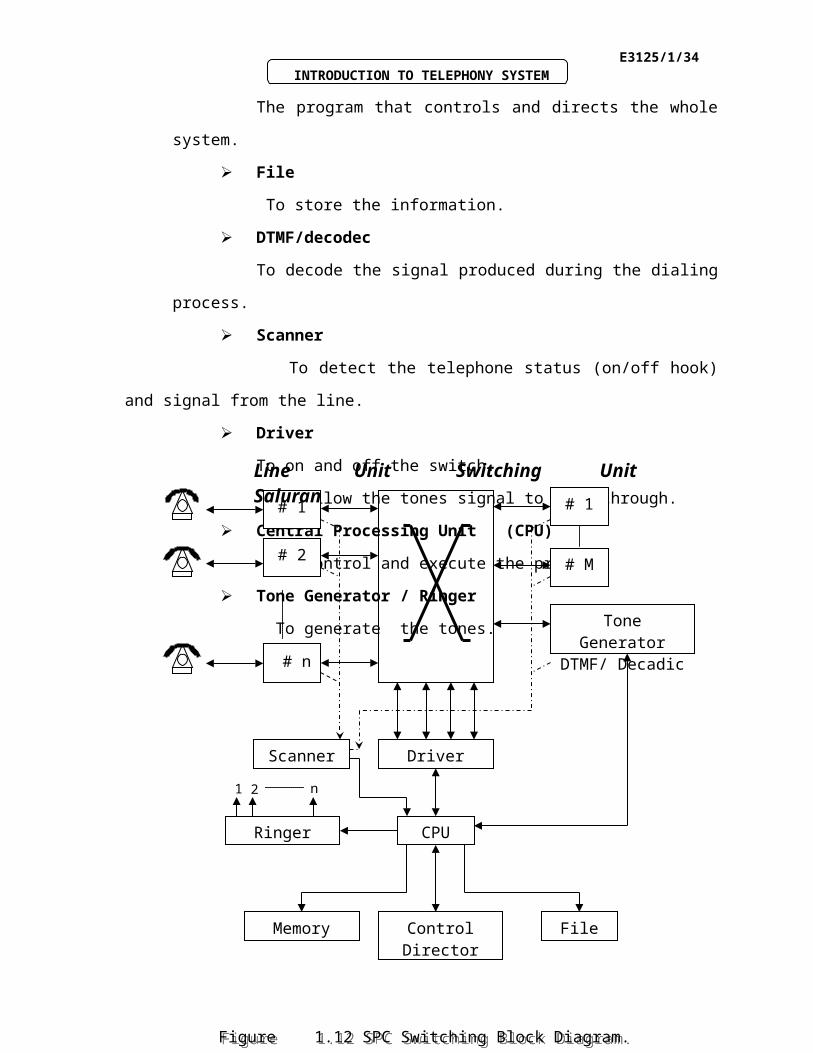
1.9.3 Stored Program Control (SPC)
The Stored Program Control (SPC) is a method of switching using computer
to process a call automatically. The computer will operate based on a certain
program which can be changed whenever it is needed.
Figure 1.12 shows the block diagram of the SPC system.
Memory
To store the user’s activities status in the form of software..
Control Director
The program that controls and directs the whole system.
File
To store the information.
DTMF/decodec
To decode the signal produced during the dialing process.
Scanner
To detect the telephone status (on/off hook) and signal from the line.
Driver
To on and off the switch.
To allow the tones signal to pass through.
Central Processing Unit (CPU)
To control and execute the program.
Tone Generator / Ringer
To generate the tones.
Figure 1.11 The Selector SwitchFigure 1.11 The Selector Switch
E3125/1/26INTRODUCTION TO TELEPHONY SYSTEM
SPC Exchange Switching Process
# 1
# 2
# 1
# M
Tone Generator DTMF/ Decadic
Scanner Driver
CPURinger
Memory Control Director
File
# n
1 2 n
Line Unit Switching Unit Saluran
Figure 1.12 SPC Switching Block Diagram.Figure 1.12 SPC Switching Block Diagram.
E3125/1/27INTRODUCTION TO TELEPHONY SYSTEM
i. If caller A picks up the telephone set (off hook) , the line will be
activated and this will be automatically detected by the scanner.
ii. The scanner will identify the location and condition of caller A and
inform the CPU.
iii. Once the feedback is received, the CPU will check the status of A and
store it in the memory.
iv. The CPU will then connect A and the switching section via the driver.
The dial tone will be sent from the generator to A.
v. When A starts dialing, the dial tone will be stopped by the DTMF
(Dual Tone Multi Frequency) .
vi. The frequency representing the dialed number will be stored in the
memory.
vii. The CPU will identify types of call and the destination.
viii. The driver will drive the switching equipment to create a path
between A and B.
ix. The CPU will instruct the ringer to produce the ringing tone for
receiver B. The ringing tone will be sent to caller A simultaneously.
x. When B picks up the set, the scanner will detect the answering signal
and send it to the CPU. The CPU will direct the ringer to stop the
ringing tone and starts the timer .
xi. After the communication, if anyone of the users hangs up, the scanner
will detect the stop signal and send it to the CPU.
xii. The CPU will store the user’s bill.
The Advantages of the SPC
E3125/1/28INTRODUCTION TO TELEPHONY SYSTEM
a) The monitoring and maintenance will be easier by inspecting the
program.
b) The signaling from the exchange can be operated more efficiently.
Any increase in the number of lines will not need the upgrading of the
signaling equipment.
c) The maintenance cost is low and the speed is faster.
The Disadvantages of the SPC.
a) Any single minor breakdown will cease the operation of the
exchange.
b) Will need proper air-conditioned room.
E3125/1/29INTRODUCTION TO TELEPHONY SYSTEM
Example 1.3
Elaborate what is meant by the Public Switching Telephone Network (PSTN)
Solution to Example 1.3
PSTN (Public Switching Telephone Network) is the world's collection of
interconnected voice-oriented public telephone networks. The PSTN consists of a
digital backbone of switched circuits together with the analog local loop wiring still
found in many residences. The PSTN provides the most popular basis for creating
wide area networks (WANs) through both leased lines and dial-up lines between
local and remote networks. PSTN is often used in wide area networking because its
ubiquitous nature local loop connections exist almost everywhere in the world.
E3125/1/30INTRODUCTION TO TELEPHONY SYSTEM
Activity 1C
TEST OUR UNDERSTANDING BEFORE YOU CONTINUE WITH THE
NEXT INPUT…!
1.5 True or false. The PSTN provides the most popular basis for creating wide
area networks (WANs) through both leased lines and dial-up lines between
local and remote networks.
1.6 State THREE types of telephone switching and mention the main differences
between them.
1.7 Define THREE functions of the switch in the telephone exchange.
E3125/1/31INTRODUCTION TO TELEPHONY SYSTEM
Feedback To Activity 1C
1.5 True
1.6 Matrix (electromechanical), Step by Step (auto electromechanical) and Stored
Program Control (fully computerized).
1.7 a) Identify the subscriber’s location
b) Set up the communication path
c) Supervise the call
E3125/1/32INTRODUCTION TO TELEPHONY SYSTEM
KEY FACTS
1. In the older telephone, the use of a rotary dialing mechanism produces what is
known as pulse dialing.
2. For the newer telephone, it uses a dialing system known as touchtone. It is also
referred to as the dual tone multi frequency (DTMF) .
3. Do you know that telephones are connected directly by twisted-pair cable to a
local exchange. Each exchange (identified by the first three digits of a phone
number) can serve up to 10000 lines.
E3125/1/33INTRODUCTION TO TELEPHONY SYSTEM
SELF-ASSESSMENT
You are approaching success. Try all the questions in this self-assessment section
and check your answers with those given in the Feedback on Self-Assessment given
on the next page. If you face any problems, discuss it with your lecturer. Good luck.
Question 1-1
a. What is the name of the building or facility to which every telephone is
connected?
Question 1-2
a. Briefly define the terms MDF, DTMF and MSC.
b. List FOUR possible functions of the cabinet.
c. Explain the process of the telephone connection between two subscribers.
d. What is the difference between the upper cable and the underground cable.
Question 1-3
a. Explain briefly the disadvantages of a step-by-step exchange.
b. PSTN (Public Switching Telephone Network) is the collection of interconnected
voice-oriented public telephone networks. Name the FOUR important switching
networks in the PSTN and explain.
c. Based on the diagram in figure 1.10, name the type of the telephone switching
system. Explain the connection that is involved in order to activate “j” switch.
E3125/1/34INTRODUCTION TO TELEPHONY SYSTEM
d. The Stored Program Control (SPC) is a method of switching using computer
to process a call automatically. Name all the empty blocks in figure 1.12.
Figure 1.12
# 1
# 2
# 1
# M
# n
1 2 n
Line Unit Switching Line Unit
1 a b c d 1 a b c d
2 e f g h2 e f g h
Input 3 i j k lInput 3 i j k l
4 m n o p4 m n o p
1 2 3 4 1 2 3 4Output Output
Figure 1.10 The Matrix SwitchingFigure 1.10 The Matrix Switching
E3125/1/35INTRODUCTION TO TELEPHONY SYSTEM
Feedback To Self-Assessment
Have you tried the questions????? If “YES”, check your answers now.
Answer 1-1
a. The telephone exchange.
Answer 1-2
a. MDF – Main Distribution Frame.
DTMF- Dual Tone Multi Frequency
MSC – Main Switching Center.
b. The Cabinet’s functions are as follows :
i. To save the usage of cable and replacing cable would be easier.
ii. To avoid the joint to be opened and this would save cost and time.
iii. To act as a place to perform maintenance checking.
iv. To upgrade the arrangement of lines.
c.
1
2
3
4
5 5
6 6
SU
BS
CR
IBE
R A
SA S
UB
SC
RIB
ER
B
LO
CA
L E
XC
HA
NG
E
E3125/1/36INTRODUCTION TO TELEPHONY SYSTEM
1. When Subscriber A picks up the telephone set, Local Exchange will
detect a call request signal from Subscriber A..
2. Local Exchange will send a dial tone to Subscriber A.
3. Subscriber A starts to dial the numbers. The numbers received will be
tested by the Local Exchange.
4. If the numbers are valid, Local Exchange will test whether the line is
available or not.
5. If the line is available, Local Exchange will do the connection. Local
Exchange will send a ringing tone to Subscriber A and the signal to
ring the Subscriber B’s telephone. Subscriber B will pick up the
telephone set, thus making the dialing tone stop.
6. If either one of the subscribers hangs up the phone , communication
will be disconnected and the Local Exchange will clear the line.
d. Upper Cable :The upper cable is used to make connection with the
customers using the DP Box. The two wire cable is normally used.
Underground Cable : The underground cable is connected to the cabinet
from the DP through man-holes. The underground cable will end at the
telephone exchange.
Answer 1-3
a. The disadvantages of the Step-by-Step switch were:
Power : Required a large amount of electricity to move switch components
for call processing
Floor Space: Major switch components were made of brass, copper and
magnets which were so heavy that required steel reinforcement in the floors
where they were installed
E3125/1/37INTRODUCTION TO TELEPHONY SYSTEM
High Maintenance: The large number of moving parts in this switch
required constant dusting and oiling to ensure connections could be made
inside the switch
Noise: The contacts were chattering as a physical path was set up through the
switch for call processing.
b. Concentrator: The concentrator unit is controlled directly by the local exchange.
All the subscribers can be connected simultaneously at the different channels.
This will reduce the cost of installation and maintenance.
Distributor : Distributor is a network in the middle of the concentrator
and the expander as shown in figure 1.8. This unit will connect thousands of
subsribers in stages .
Expander : This unit will expand the actual number of lines giong into the
concentrator. The switching process for the expander and the concentrator
relies on the number of lines being activated simultaneously.
Multiplexer : The function of the unit is to send signals from multiple
sources through the single channel. This will reduce the number of lines
needed. Some of the multiplexing techniques that are widely used are the
Time Division Multiplexing (TDM) and Frequency Division Multiplexing
(FDM). Demultiplexing is the technique to regain the input signals at the
receiver.
Combination of all these networks will form a complete PSTN.
c. To activate “j” switch, the input channel 3 and output channel 2 must be connected.
d.
E3125/1/38INTRODUCTION TO TELEPHONY SYSTEM
# 1
# 2
# 1
# M
Tone Generator DTMF/ Decadic
Scanner Driver
CPURinger
Memory Control Director
File
# n
1 2 n
Line Unit Switching Line Unit