e3z - omron on trascon...
TRANSCRIPT
E3Z 1
Photoelectric Sensor with Built-in Amplifier
E3ZFor almost all binaray-detection applications, you can make selection from the E3Z
Features
Basicperformance
Reliability
East-to-operate
Environmentalprotection
Globalization
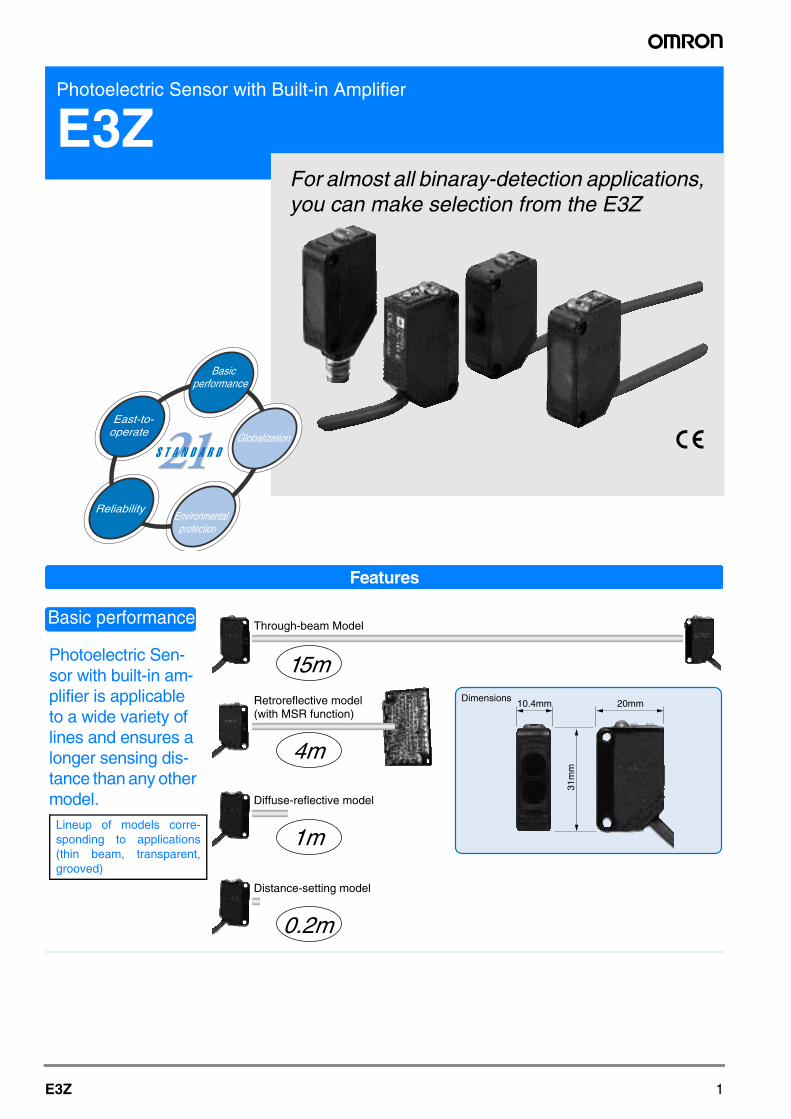
Photoelectric Sen-sor with built-in am-plifier is applicable to a wide variety of lines and ensures a longer sensing dis-tance than any other model.
Basic performance
Lineup of models corre-sponding to applications(thin beam, transparent,grooved)
Through-beam Model
Retroreflective model (with MSR function)
15m
Diffuse-reflective model
1m
4m
Dimensions 10.4mm 20mm
31m
m
Distance-setting model
0.2m
2 Photoelectric Sensors
Meets a variety of international stan-dards, thus allowing use in any country.
Global network with 191 offices in 38 countries. M8-connector, PNP output types that meetinternational standards are available.
User-friendly Pho-toelectric Sensor takes all installation and on-site condi-tions into consider-ation.
A general-purpose connector ensures easy on-site installation!
The compact and space-saving model can beinstalled in any location.
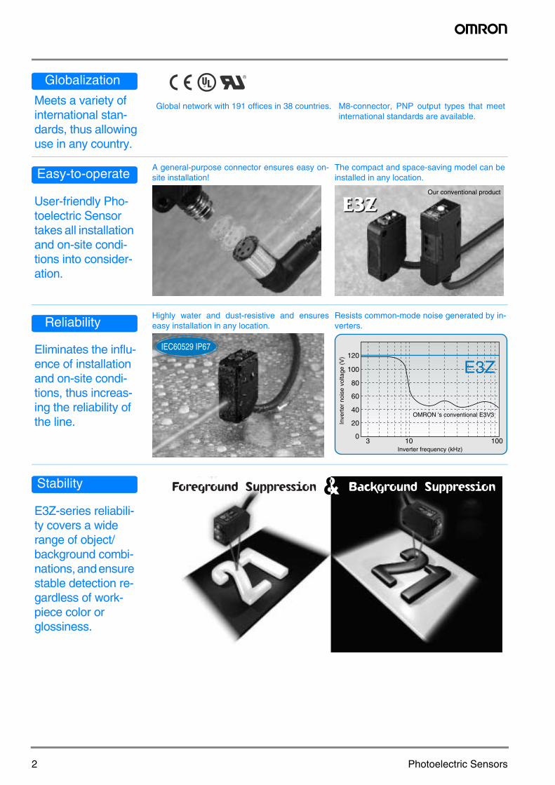
Eliminates the influ-ence of installation and on-site condi-tions, thus increas-ing the reliability of the line.
Highly water and dust-resistive and ensureseasy installation in any location.
Resists common-mode noise generated by in-verters.
E3Z-series reliabili-ty covers a wide range of object/background combi-nations, and ensure stable detection re-gardless of work-piece color or glossiness.
Globalization
Easy-to-operateOur conventional product
Reliability
IEC60529 IP67
0
20
40
60
80
100
120
3 10 100Inverter frequency (kHz)
Inve
rter
noi
se v
olta
ge (
V)
OMRON 's conventional E3V3
E3Z
Stability
3E3Z
Photoelectric Sen-sor with Built-in Am-plifier
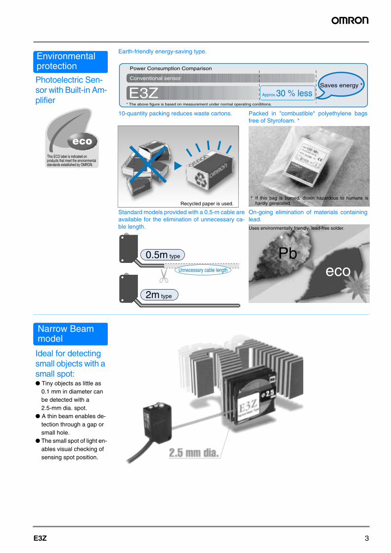
Earth-friendly energy-saving type.
10-quantity packing reduces waste cartons. Packed in "combustible" polyethylene bagsfree of Styrofoam. *
Standard models provided with a 0.5-m cable areavailable for the elimination of unnecessary ca-ble length.
On-going elimination of materials containinglead.
Ideal for detecting small objects with a small spot: Tiny objects as little as
0.1 mm in diameter can be detected with a 2.5-mm dia. spot.
A thin beam enables de-tection through a gap or small hole.
The small spot of light en-ables visual checking of sensing spot position.
Environmentalprotection
This ECO label is indicated on products that meet the environmental standards established by OMRON.
E3Z
Power Consumption Comparison
Conventional sensor
Approx.30 % lessSaves energy *
* The above figure is based on measurement under normal operating conditions.
Recycled paper is used.* If this bag is burned, dioxin hazardous to humans is
hardly generated.
0.5m type
2m type
Unnecessary cable length
Uses environmentally friendly, lead-free solder.
ecoPb
Narrow Beam model
4 Photoelectric Sensors
Stable detection of thin-wall PET bottles adequate for recyclingStandard-size transparent object sensor Uses OMRON's unique
optical system ("Inner
View") that can detect
various shapes of PET
bottles and transparent
objects.
Detects a wide range of bott-
les from 500-ml bottles to
2-l bottles, and from single
bottles to sets of stocked
bottles.
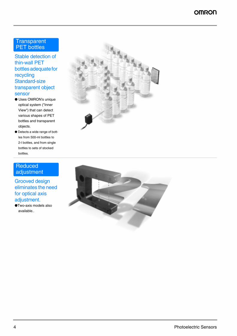
Grooved design eliminates the need for optical axis adjustment.Two-axis models also
available..
TransparentPET bottles
Reducedadjustment
5E3Z
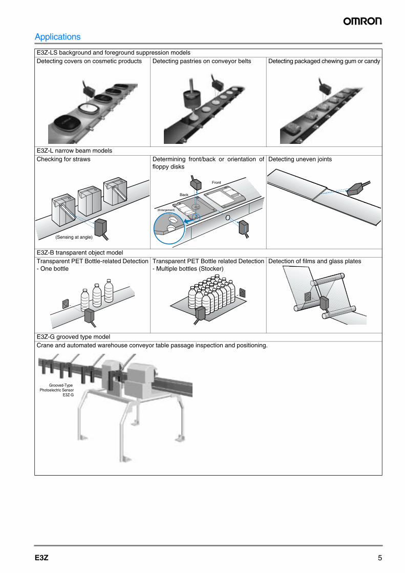
Applications
E3Z-LS background and foreground suppression modelsDetecting covers on cosmetic products Detecting pastries on conveyor belts Detecting packaged chewing gum or candy
E3Z-L narrow beam modelsChecking for straws Determining front/back or orientation of
floppy disksDetecting uneven joints
E3Z-B transparent object modelTransparent PET Bottle-related Detection- One bottle
Transparent PET Bottle related Detection- Multiple bottles (Stocker)
Detection of films and glass plates
E3Z-G grooved type modelCrane and automated warehouse conveyor table passage inspection and positioning.
(Sensing at angle)
(Enlargement)
Back
Front
Grooved-TypePhotoelectric Sensor
E3Z-G
6 Photoelectric Sensors
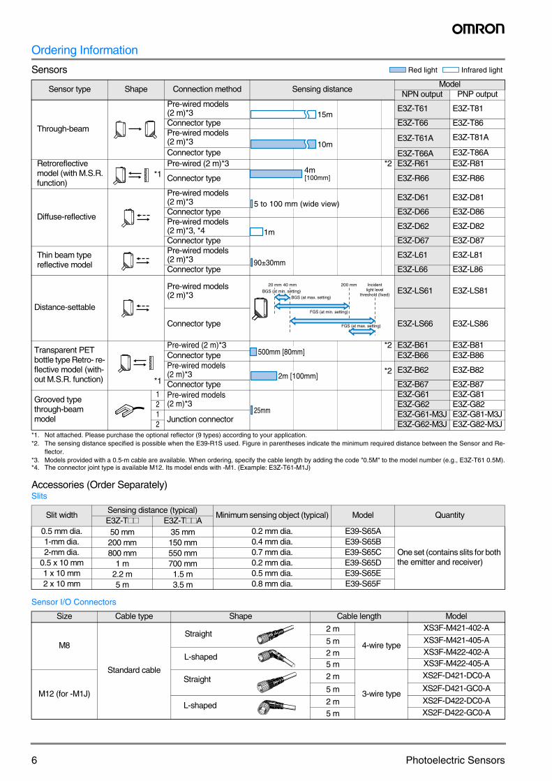
Ordering Information
Sensors
Accessories (Order Separately)Slits
Sensor I/O Connectors
Sensor type Shape Connection method Sensing distanceModel
NPN output PNP output
Through-beam
Pre-wired models(2 m)*3 E3Z-T61 E3Z-T81
Connector type E3Z-T66 E3Z-T86Pre-wired models(2 m)*3 E3Z-T61A E3Z-T81A
Connector type E3Z-T66A E3Z-T86ARetroreflective model (with M.S.R. function)
*1
*1. Not attached. Please purchase the optional reflector (9 types) according to your application.
Pre-wired (2 m)*3 *2
*2. The sensing distance specified is possible when the E39-R1S used. Figure in parentheses indicate the minimum required distance between the Sensor and Re-flector.
E3Z-R61 E3Z-R81
Connector type E3Z-R66 E3Z-R86
Diffuse-reflective
Pre-wired models(2 m)*3
*3. Models provided with a 0.5-m cable are available. When ordering, specify the cable length by adding the code "0.5M" to the model number (e.g., E3Z-T61 0.5M).
E3Z-D61 E3Z-D81
Connector type E3Z-D66 E3Z-D86Pre-wired models(2 m)*3, *4
*4. The connector joint type is available M12. Its model ends with -M1. (Example: E3Z-T61-M1J)
E3Z-D62 E3Z-D82
Connector type E3Z-D67 E3Z-D87
Thin beam type reflective model
Pre-wired models(2 m)*3 E3Z-L61 E3Z-L81
Connector type E3Z-L66 E3Z-L86
Distance-settable
Pre-wired models (2 m)*3 E3Z-LS61 E3Z-LS81
Connector type E3Z-LS66 E3Z-LS86
Transparent PET bottle type Retro- re-flective model (with-out M.S.R. function) *1
Pre-wired (2 m)*3 *2 E3Z-B61 E3Z-B81Connector type E3Z-B66 E3Z-B86Pre-wired models(2 m)*3 *2 E3Z-B62 E3Z-B82
Connector type E3Z-B67 E3Z-B87
Grooved type through-beam model
1 Pre-wired models(2 m)*3
E3Z-G61 E3Z-G812 E3Z-G62 E3Z-G821
Junction connectorE3Z-G61-M3J E3Z-G81-M3J
2 E3Z-G62-M3J E3Z-G82-M3J
Slit widthSensing distance (typical)
Minimum sensing object (typical) Model QuantityE3Z-T## E3Z-T##A
0.5 mm dia. 50 mm 35 mm 0.2 mm dia. E39-S65A
One set (contains slits for both the emitter and receiver)
1-mm dia. 200 mm 150 mm 0.4 mm dia. E39-S65B2-mm dia. 800 mm 550 mm 0.7 mm dia. E39-S65C
0.5 x 10 mm 1 m 700 mm 0.2 mm dia. E39-S65D1 x 10 mm 2.2 m 1.5 m 0.5 mm dia. E39-S65E2 x 10 mm 5 m 3.5 m 0.8 mm dia. E39-S65F
Size Cable type Shape Cable length Model
M8
Standard cable
2 m
4-wire type
XS3F-M421-402-A
5 m XS3F-M421-405-A
2 m XS3F-M422-402-A
5 m XS3F-M422-405-A
M12 (for -M1J)
2 m
3-wire type
XS2F-D421-DC0-A
5 m XS2F-D421-GC0-A
2 m XS2F-D422-DC0-A
5 m XS2F-D422-GC0-A
Red light Infrared light
15m
10m
4m [100mm]
5 to 100 mm (wide view)
1m
90±30mm
40 mm20 mm 200 mm
BGS (at min. setting)BGS (at max. setting)
FGS (at max. setting)
FGS (at min. setting)
Incidentlight level
threshold (fixed)
500mm [80mm]
2m [100mm]
25mm
Straight
L-shaped
Straight
L-shaped
7E3Z
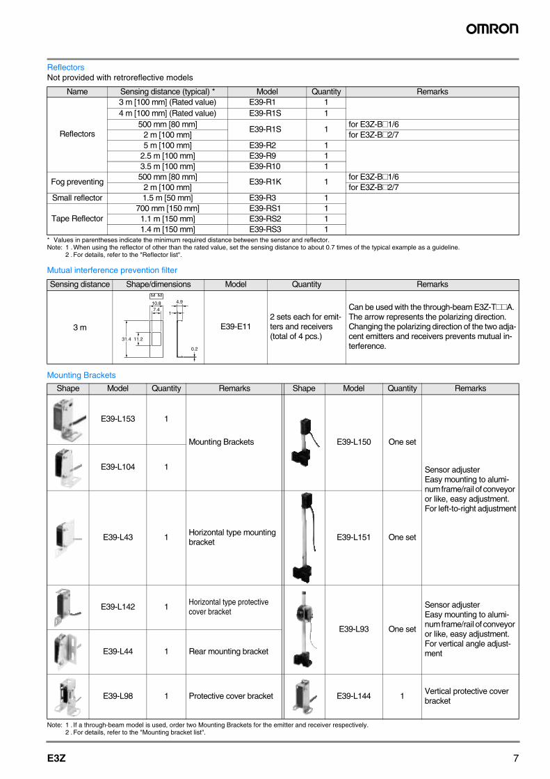
ReflectorsNot provided with retroreflective models
* Values in parentheses indicate the minimum required distance between the sensor and reflector.Note: 1 .When using the reflector of other than the rated value, set the sensing distance to about 0.7 times of the typical example as a guideline.
2 .For details, refer to the "Reflector list".
Mutual interference prevention filter
Mounting Brackets
Note: 1 . If a through-beam model is used, order two Mounting Brackets for the emitter and receiver respectively.2 .For details, refer to the "Mounting bracket list".
Name Sensing distance (typical) * Model Quantity Remarks
Reflectors
3 m [100 mm] (Rated value) E39-R1 14 m [100 mm] (Rated value) E39-R1S 1
500 mm [80 mm]E39-R1S 1
for E3Z-B#1/62 m [100 mm] for E3Z-B#2/75 m [100 mm] E39-R2 1
2.5 m [100 mm] E39-R9 13.5 m [100 mm] E39-R10 1
Fog preventing500 mm [80 mm]
E39-R1K 1for E3Z-B#1/6
2 m [100 mm] for E3Z-B#2/7Small reflector 1.5 m [50 mm] E39-R3 1
Tape Reflector700 mm [150 mm] E39-RS1 11.1 m [150 mm] E39-RS2 11.4 m [150 mm] E39-RS3 1
Sensing distance Shape/dimensions Model Quantity Remarks
3 m E39-E112 sets each for emit-ters and receivers (total of 4 pcs.)
Can be used with the through-beam E3Z-T##A. The arrow represents the polarizing direction. Changing the polarizing direction of the two adja-cent emitters and receivers prevents mutual in-terference.
Shape Model Quantity Remarks Shape Model Quantity Remarks
E39-L153 1
Mounting Brackets E39-L150 One set
Sensor adjuster Easy mounting to alumi-num frame/rail of conveyor or like, easy adjustment. For left-to-right adjustment
E39-L104 1
E39-L43 1Horizontal type mounting bracket
E39-L151 One set
E39-L142 1Horizontal type protective cover bracket
E39-L93 One set
Sensor adjuster Easy mounting to alumi-num frame/rail of conveyor or like, easy adjustment.For vertical angle adjust-mentE39-L44 1 Rear mounting bracket
E39-L98 1 Protective cover bracket E39-L144 1Vertical protective cover bracket
0.2
1
4.910.87.4
11.231.4
8 Photoelectric Sensors
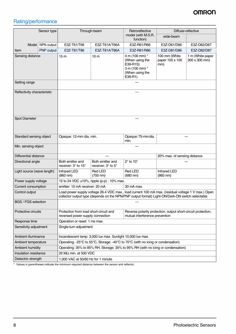
Rating/performance
* Values in parentheses indicate the minimum required distance between the sensor and reflector.
Sensor type Through-beam Retroreflective model (with M.S.R.
function)
Diffuse-reflective
wide-beam
Model NPN output E3Z-T61/T66 E3Z-T61A/T66A E3Z-R61/R66 E3Z-D61/D66 E3Z-D62/D67
Item PNP output E3Z-T81/T86 E3Z-T81A/T86A E3Z-R81/R86 E3Z-D81/D86 E3Z-D82/D87
Sensing distance 15 m 10 m 4 m (100 mm) * (When using the E39-R1S)3 m (100 mm) * (When using the E39-R1)
100 mm (White paper 100 x 100 mm)
1 m (White paper 300 x 300 mm)
Setting range ---
Reflectivity characteristic ---
Spot Diameter ---
Standard sensing object Opaque: 12-mm dia. min. Opaque: 75-mm dia. min.
---
Min. sensing object ---
Differential distance --- 20% max. of sensing distance
Directional angle Both emitter and receiver: 3° to 15°
Both emitter and receiver: 3° to 5°
2° to 10° ---
Light source (wave length) Infrared LED (860 nm)
Red LED (700 nm)
Red LED (680 nm)
Infrared LED (860 nm)
Power supply voltage 12 to 24 VDC ±10%, ripple (p-p) : 10% max.
Current consumption emitter: 15 mA receiver: 20 mA 30 mA max.
Control output Load power supply voltage 26.4 VDC max., load current 100 mA max. (residual voltage 1 V max.) Open collector output type (depends on the NPN/PNP output format) Light-ON/Dark-ON switch selectable
BGS / FGS selection ---
Protective circuits Protection from load short-circuit and reversed power supply connection
Reverse polarity protection, output short-circuit protection, mutual interference prevention
Response time Operation or reset: 1 ms max.
Sensitivity adjustment Single-turn adjustment
Ambient illuminance Incandescent lamp: 3,000 lux max. Sunlight 10,000 lux max.
Ambient temperature Operating: -25°C to 55°C, Storage: -40°C to 70°C (with no icing or condensation)
Ambient humidity Operating: 35% to 85% RH, Storage: 35% to 95% RH (with no icing or condensation)
Insulation resistance 20 MΩ min. at 500 VDC
Dielectric strength 1,000 VAC at 50/60 Hz for 1 minute
9E3Z
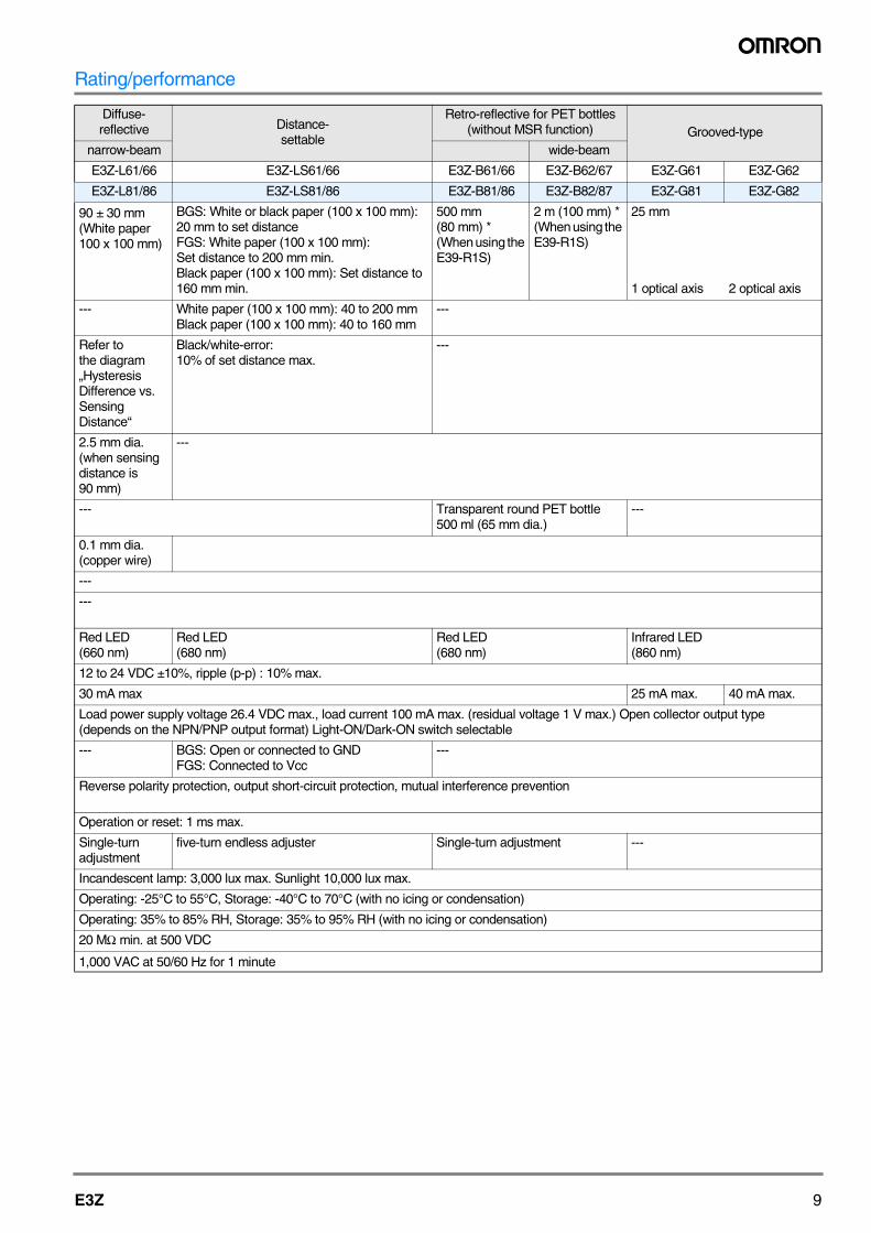
Rating/performance
Diffuse-reflective Distance-
settable
Retro-reflective for PET bottles (without MSR function) Grooved-type
narrow-beam wide-beam
E3Z-L61/66 E3Z-LS61/66 E3Z-B61/66 E3Z-B62/67 E3Z-G61 E3Z-G62
E3Z-L81/86 E3Z-LS81/86 E3Z-B81/86 E3Z-B82/87 E3Z-G81 E3Z-G82
90 ± 30 mm (White paper 100 x 100 mm)
BGS: White or black paper (100 x 100 mm): 20 mm to set distanceFGS: White paper (100 x 100 mm): Set distance to 200 mm min.Black paper (100 x 100 mm): Set distance to 160 mm min.
500 mm (80 mm) * (When using the E39-R1S)
2 m (100 mm) * (When using the E39-R1S)
25 mm
1 optical axis 2 optical axis
--- White paper (100 x 100 mm): 40 to 200 mmBlack paper (100 x 100 mm): 40 to 160 mm
---
Refer to the diagram „Hysteresis Difference vs. Sensing Distance“
Black/white-error:10% of set distance max.
---
2.5 mm dia. (when sensing distance is 90 mm)
---
--- Transparent round PET bottle 500 ml (65 mm dia.)
---
0.1 mm dia. (copper wire)
---
---
Red LED (660 nm)
Red LED (680 nm)
Red LED (680 nm)
Infrared LED (860 nm)
12 to 24 VDC ±10%, ripple (p-p) : 10% max.
30 mA max 25 mA max. 40 mA max.
Load power supply voltage 26.4 VDC max., load current 100 mA max. (residual voltage 1 V max.) Open collector output type (depends on the NPN/PNP output format) Light-ON/Dark-ON switch selectable
--- BGS: Open or connected to GNDFGS: Connected to Vcc
---
Reverse polarity protection, output short-circuit protection, mutual interference prevention
Operation or reset: 1 ms max.
Single-turn adjustment
five-turn endless adjuster Single-turn adjustment ---
Incandescent lamp: 3,000 lux max. Sunlight 10,000 lux max.
Operating: -25°C to 55°C, Storage: -40°C to 70°C (with no icing or condensation)
Operating: 35% to 85% RH, Storage: 35% to 95% RH (with no icing or condensation)
20 MΩ min. at 500 VDC
1,000 VAC at 50/60 Hz for 1 minute
10 Photoelectric Sensors
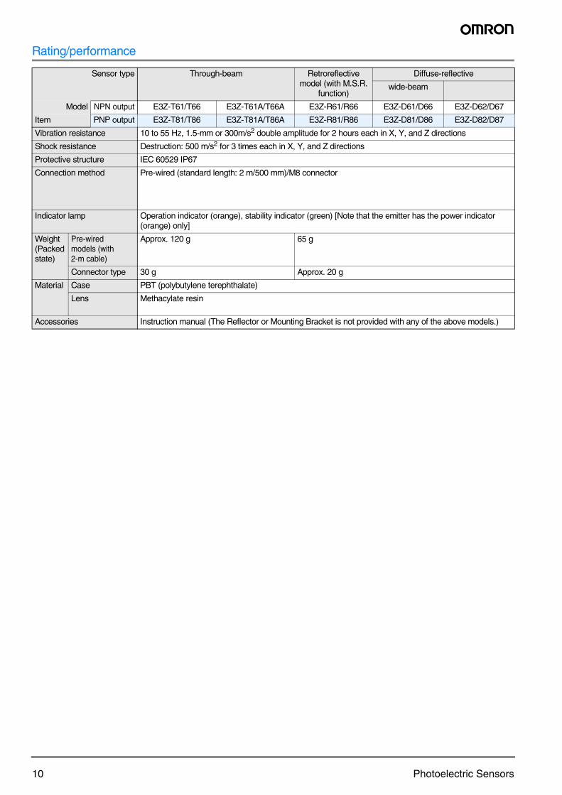
Rating/performance
Sensor type Through-beam Retroreflective model (with M.S.R.
function)
Diffuse-reflective
wide-beam
Model NPN output E3Z-T61/T66 E3Z-T61A/T66A E3Z-R61/R66 E3Z-D61/D66 E3Z-D62/D67
Item PNP output E3Z-T81/T86 E3Z-T81A/T86A E3Z-R81/R86 E3Z-D81/D86 E3Z-D82/D87
Vibration resistance 10 to 55 Hz, 1.5-mm or 300m/s2 double amplitude for 2 hours each in X, Y, and Z directions
Shock resistance Destruction: 500 m/s2 for 3 times each in X, Y, and Z directions
Protective structure IEC 60529 IP67
Connection method Pre-wired (standard length: 2 m/500 mm)/M8 connector
Indicator lamp Operation indicator (orange), stability indicator (green) [Note that the emitter has the power indicator (orange) only]
Weight (Packed state)
Pre-wiredmodels (with 2-m cable)
Approx. 120 g 65 g
Connector type 30 g Approx. 20 g
Material Case PBT (polybutylene terephthalate)
Lens Methacylate resin
Accessories Instruction manual (The Reflector or Mounting Bracket is not provided with any of the above models.)
11E3Z
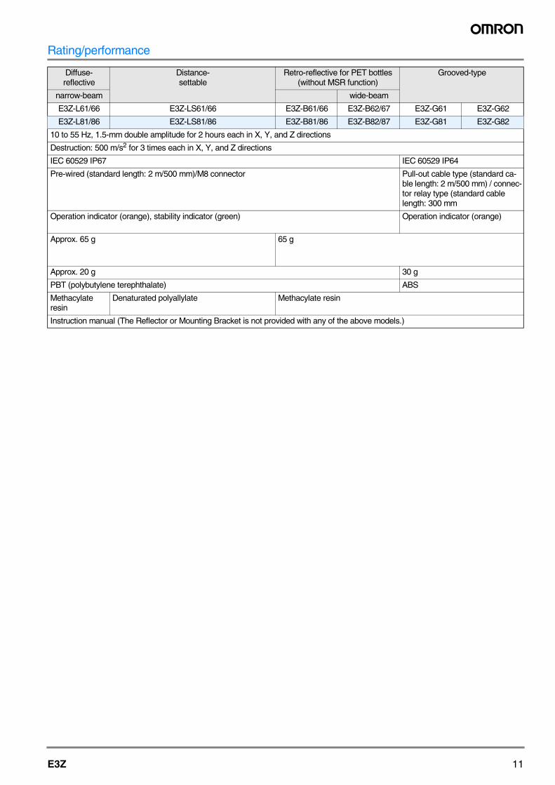
Rating/performance
Diffuse-reflective
Distance-settable
Retro-reflective for PET bottles (without MSR function)
Grooved-type
narrow-beam wide-beam
E3Z-L61/66 E3Z-LS61/66 E3Z-B61/66 E3Z-B62/67 E3Z-G61 E3Z-G62
E3Z-L81/86 E3Z-LS81/86 E3Z-B81/86 E3Z-B82/87 E3Z-G81 E3Z-G82
10 to 55 Hz, 1.5-mm double amplitude for 2 hours each in X, Y, and Z directions
Destruction: 500 m/s2 for 3 times each in X, Y, and Z directions
IEC 60529 IP67 IEC 60529 IP64
Pre-wired (standard length: 2 m/500 mm)/M8 connector Pull-out cable type (standard ca-ble length: 2 m/500 mm) / connec-tor relay type (standard cable length: 300 mm
Operation indicator (orange), stability indicator (green) Operation indicator (orange)
Approx. 65 g 65 g
Approx. 20 g 30 g
PBT (polybutylene terephthalate) ABS
Methacylate resin
Denaturated polyallylate Methacylate resin
Instruction manual (The Reflector or Mounting Bracket is not provided with any of the above models.)
12 Photoelectric Sensors
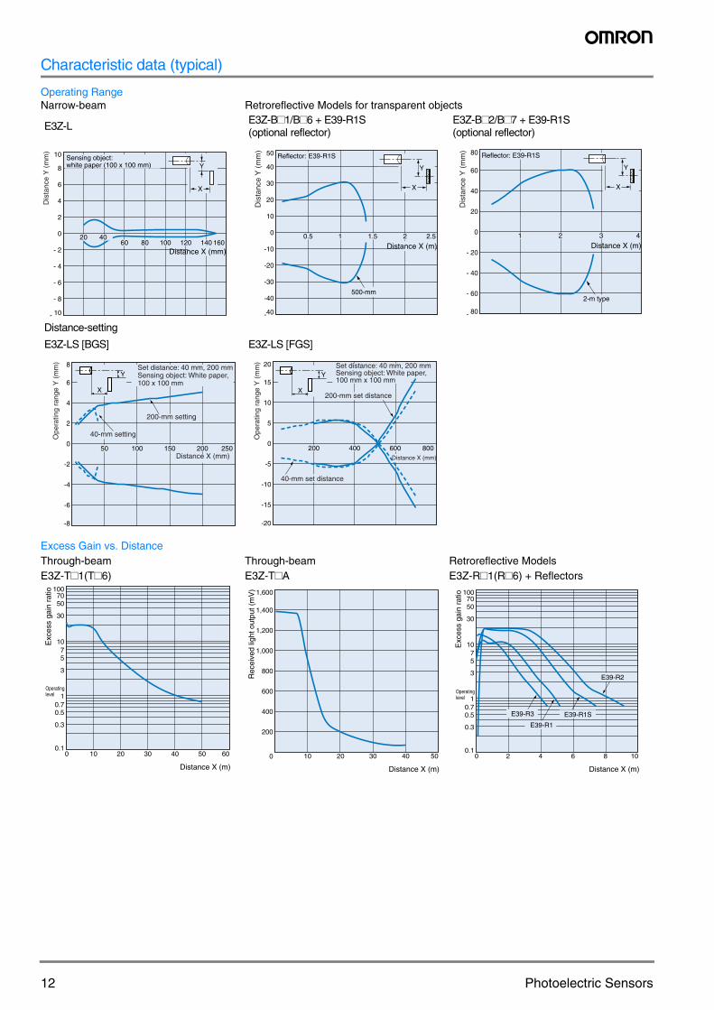
Characteristic data (typical)
Operating RangeNarrow-beam Retroreflective Models for transparent objects
E3Z-LE3Z-B#1/B#6 + E39-R1S (optional reflector)
E3Z-B#2/B#7 + E39-R1S (optional reflector)
Distance-setting
E3Z-LS [BGS] E3Z-LS [FGS]
Excess Gain vs. DistanceThrough-beam Through-beam Retroreflective ModelsE3Z-T#1(T#6) E3Z-T#A E3Z-R#1(R#6) + Reflectors
10
8
6
4
2
0
- 2
- 4
- 6
- 8
- 10
806040
100 120 140 16020
Distance X (mm)
Sensing object:white paper (100 x 100 mm) Y
X
Dis
tanc
e Y
(m
m)
Y
X
50
40
30
20
10
0
-10
-20
-30
-40
-40
0.5 2.51 1.5 2
Distance X (m)
Reflector: E39-R1S
500-mm
Dis
tanc
e Y
(m
m)
Y
X
80
60
40
20
0
- 20
- 40
- 60
- 80
2 41 3
Distance X (m)
Reflector: E39-R1S
2-m type
Dis
tanc
e Y
(m
m)
8
6
4
2
0
-2
-4
-6
-8
50 100 150 200 250
X
YSet distance: 40 mm, 200 mmSensing object: White paper,100 x 100 mm
200-mm setting
40-mm setting
Distance X (mm)
Ope
ratin
g ra
nge
Y (
mm
) 20
15
10
5
0
-5
-10
-15
-20
200 400 600 800
X
Y
40-mm set distance
200-mm set distance
Distance X (mm)
Set distance: 40 mm, 200 mmSensing object: White paper,100 mm x 100 mm
Ope
ratin
g ra
nge
Y (
mm
)
1007050
30
1075
3
10.70.5
0.3
0.10 10 20 30 40 50 60
Distance X (m)
Exc
ess
gain
rat
io
Operatinglevel
1,600
1,400
1,200
1,000
800
600
400
200
0 10 20 30 40 50
Distance X (m)
Rec
eive
d lig
ht o
utpu
t (m
V) 100
7050
30
1075
3
10.70.5
0.3
0.10 2 4 6 8 10
Distance X (m)
E39-R3 E39-R1S
E39-R2
E39-R1
Exc
ess
gain
rat
io
Operatinglevel
13E3Z
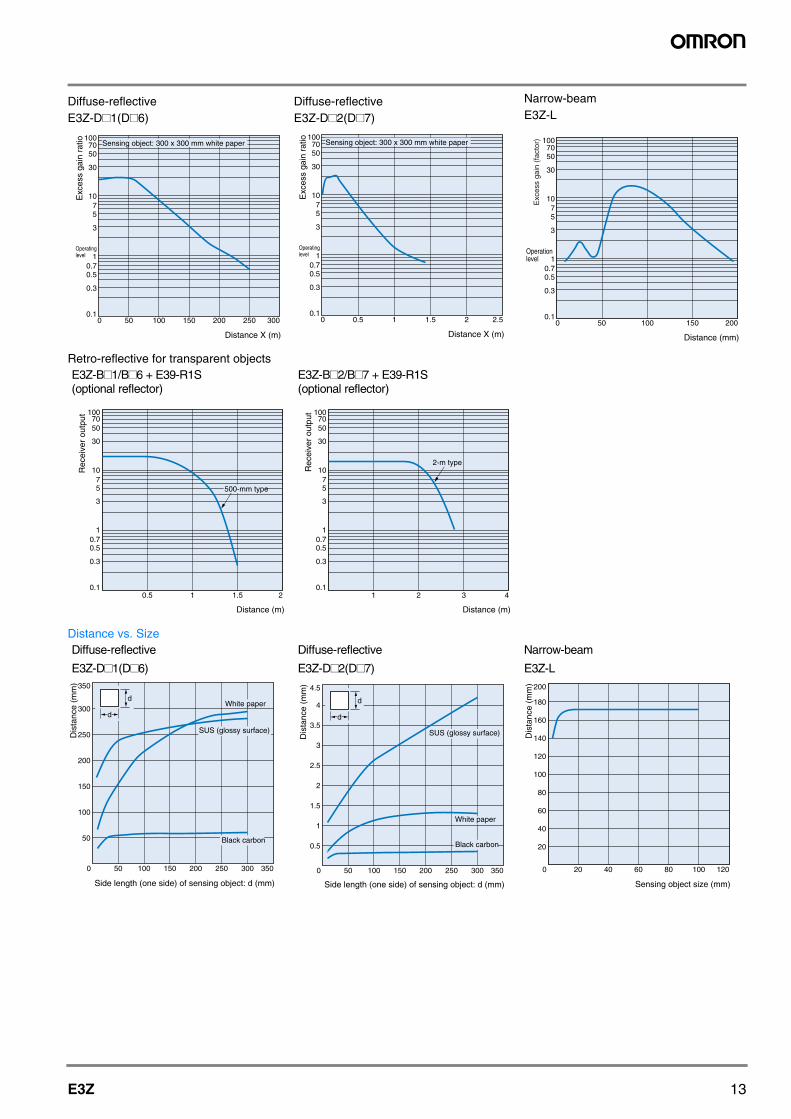
Diffuse-reflective Diffuse-reflective Narrow-beam
E3Z-D#1(D#6) E3Z-D#2(D#7) E3Z-L
Retro-reflective for transparent objectsE3Z-B#1/B#6 + E39-R1S (optional reflector)
E3Z-B#2/B#7 + E39-R1S (optional reflector)
Distance vs. SizeDiffuse-reflective Diffuse-reflective Narrow-beam
E3Z-D#1(D#6) E3Z-D#2(D#7) E3Z-L
1007050
30
1075
3
10.70.5
0.3
0.10 50 100 150 200 250 300
Distance X (m)
Sensing object: 300 x 300 mm white paper
Exc
ess
gain
rat
io
Operatinglevel
1007050
30
1075
3
10.70.5
0.3
0.10 0.5 1 1.5 2 2.5
Distance X (m)
Sensing object: 300 x 300 mm white paper
Exc
ess
gain
rat
io
Operatinglevel
1007050
30
1075
3
10.70.5
0.3
0.10 50 100 150 200
Distance (mm)
Operationlevel
Exc
ess
gain
(fa
ctor
)
0.5 1 1.5 2
Distance (m)
Rec
eive
r ou
tput
1007050
30
1075
3
10.70.5
0.3
0.1
500-mm type
1 2 3 4
Distance (m)
Rec
eive
r ou
tput 100
7050
30
1075
3
10.70.5
0.3
0.1
2-m type
350
300
250
200
150
100
50
350300250200150100500
Side length (one side) of sensing object: d (mm)
Dis
tanc
e (m
m)
Black carbon
SUS (glossy surface)
White paperd
d
4.5
4
3.5
3
2.5
2
1.5
1
0.5
350300250200150100500
Black carbon
White paper
d
d
Side length (one side) of sensing object: d (mm)
Dis
tanc
e (m
m)
SUS (glossy surface)
200
180
160
140
120
100
80
60
40
20
120100806040200
Sensing object size (mm)
Dis
tanc
e (m
m)
14 Photoelectric Sensors
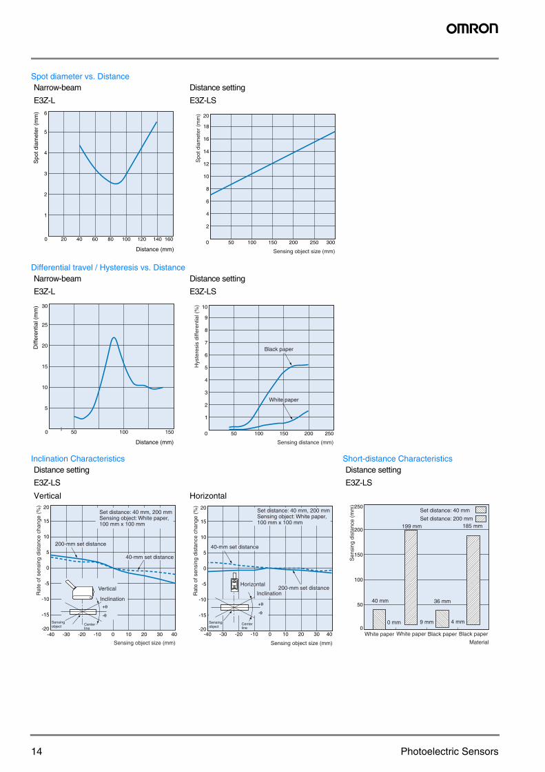
Spot diameter vs. DistanceNarrow-beam Distance setting
E3Z-L E3Z-LS
Differential travel / Hysteresis vs. DistanceNarrow-beam Distance setting
E3Z-L E3Z-LS
Inclination Characteristics Short-distance CharacteristicsDistance setting Distance setting
E3Z-LS E3Z-LS
Vertical Horizontal
6
5
4
3
2
1
1601401208040 10060200
Distance (mm)
Spo
t dia
met
er (
mm
)
Spo
t dia
met
er (
mm
)
Sensing object size (mm)
20
18
16
14
12
10
8
6
4
2
0 30025020015010050
30
25
20
15
10
5
150100500
Distance (mm)
Diff
eren
tial (
mm
) 10
9
8
7
6
5
4
3
2
1
250200150100500
White paper
Hys
tere
sis
diffe
rent
ial (
%)
Sensing distance (mm)
Black paper
-40 -30 -20 -10 0 10 20 30
-q
+q
20
15
10
5
0
-5
-10
-15
-2040
Set distance: 40 mm, 200 mmSensing object: White paper,100 mm x 100 mm
200-mm set distance
40-mm set distance
Vertical
Sensingobject Center
line
Inclination
-q
+q
Rat
e of
sen
sing
dis
tanc
e ch
ange
(%
)
Sensing object size (mm)
Centerline
20
15
10
5
0
-5
-10
-15
-20-40 -30 -20 -10 0 10 20 30 40
200-mm set distance
Sensingobject
-q
Set distance: 40 mm, 200 mmSensing object: White paper,100 mm x 100 mm
40-mm set distance
Horizontal
Inclination
+q
Rat
e of
sen
sing
dis
tanc
e ch
ange
(%
)
Sensing object size (mm)
250
200
150
100
50
0
Set distance: 40 mm
Set distance: 200 mm
40 mm
0 mm 9 mm
199 mm 185 mm
4 mm
36 mm
Sen
sing
dis
tanc
e (m
m)
Material
White paper White paper Black paper Black paper
15E3Z
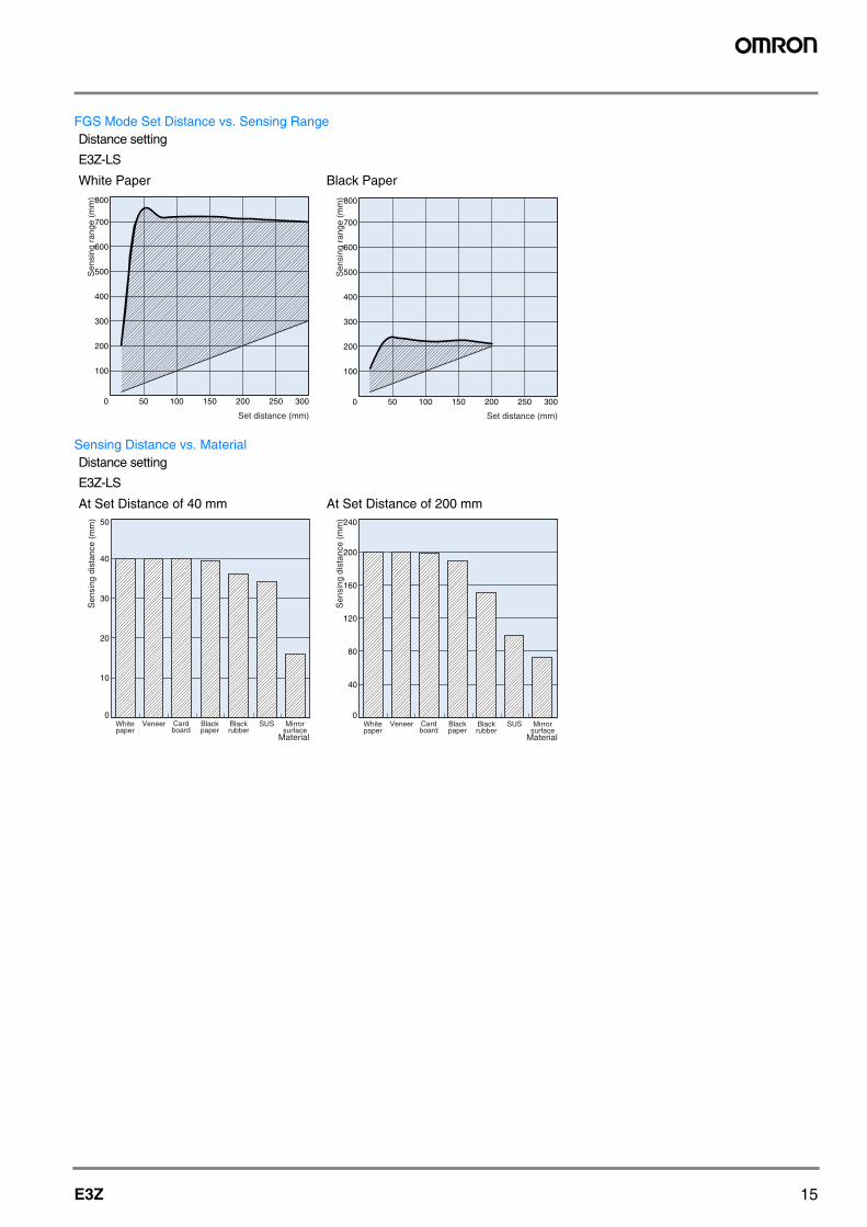
FGS Mode Set Distance vs. Sensing RangeDistance setting
E3Z-LS
White Paper Black Paper
Sensing Distance vs. MaterialDistance setting
E3Z-LS
At Set Distance of 40 mm At Set Distance of 200 mm
800
700
600
500
400
300
200
100
300250200150100500
Sen
sing
ran
ge (
mm
)
Set distance (mm)
800
700
600
500
400
300
200
100
300250200150100500
Sen
sing
ran
ge (
mm
)
Set distance (mm)
50
40
30
20
10
0
Sen
sing
dis
tanc
e (m
m)
Material
Whitepaper
Veneer Cardboard
Blackpaper
Blackrubber
SUS Mirrorsurface
240
200
160
120
80
40
0
Sen
sing
dis
tanc
e (m
m)
Material
Whitepaper
Veneer Cardboard
Blackpaper
Blackrubber
SUS Mirrorsurface
16 Photoelectric Sensors
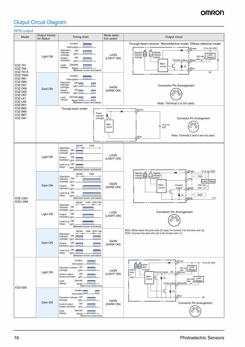
Output Circuit Diagram
NPN output
Model Output transis-tor Status Timing chart Mode selec-
tion switch Output circuit
E3Z-T61E3Z-T66E3Z-T61AE3Z-T66AE3Z-R61 E3Z-R66 E3Z-D61 E3Z-D66 E3Z-D62 E3Z-D67E3Z-L61E3Z-L66E3Z-B61E3Z-B62E3Z-B66E3Z-B67E3Z-G61
Light ON L•ON(LIGHT ON)
Dark ON D•ON(DARK ON)
E3Z-LS61E3Z-LS66
Light ON L•ON(LIGHT ON)
BGS: Either leave the pink wire (2) open or connect it to the blue wire (3).FGS: Connect the pink wire (2) to the brown wire (1).
Dark ON D•ON(DARK ON)
Light ON L•ON(LIGHT ON)
Dark ON D•ON(DARK ON)
E3Z-G62
Light ON L•ON(LIGHT ON)
Dark ON D•ON(DARK ON)
Incident
Interrupted
ON
OFF
ON
OFF
Operate
Reset
Operationindicator(orange)
(Between brown and black)
Outputtransistor
Load(Relay)
Through-beam receiver Retroreflective model Diffuse-reflective model
Connector Pin Arrangement
Note: Terminal 2 is not used.
4
1
2 43
3
112 to 24 VDCBrown
BlackControl output
Blue
100 mA max.
Operationindicator(orange)
Stabilityindicator(green)
0V
ZD
Load(Relay)
Maincircuit
Incident
Interrupted
ON
OFF
ON
OFF
Operate
Reset(Between brown and black)
Operationindicator(orange)Outputtransistor
Load(Relay)
Through-beam emitter
Powerindicator(orange)
Maincircuit
3
1
12 to 24 VDC
Brown
Blue
Connector Pin Arrangement
Note: Terminal 2 and 4 are not used.
1
2 43
ON
OFF
ON
OFF
ON
OFF
NEAR FAROperationindicator(orange)
Outputtransistor
Load (e.g.relay)
(Between brown and black)
1
2 43
4
2
1
3
Connector Pin Arrangement
12 to 24 VDCBrown
BlackControloutput
Blue
100 mA max.
Operationindicator(orange)
Stabilityindicator(green)
ZD
Load (Relay)
Maincircuit
PinkFGS
BGS0 V
ON
OFF
ON
OFF
ON
OFF
NEAR FAROperationindicator(orange)
Outputtransistor
Load (e.g.relay)
(Between brown and black)
ON
OFF
ON
OFF
ON
OFF
NEAR FAR VERY FAROperationindicator(orange)
Outputtransistor
Load (e.g.relay)
(Between brown and black)
ON
OFF
ON
OFF
ON
OFF
NEAR FAR VERY FAROperationindicator(orange)
Outputtransistor
Load (e.g.relay)
(Between brown and black)
(Between brown and black (white)
Incident
Interrupted
ON
OFF
ON
OFF
Operate
Reset
Operation indicator (orange)
Control outputOutput transistor
Load(Relay)
12 to 24 VDC
0V
Load(Relay)
Connector Pin arrangement
1
2 43
3
2(Control output)
ZD
(S2)White
100 mA max.
Load(Relay)
100 mA max.
(S1)4
1Brown
OperationindicatorS 2 (orange)
Maincircuit
OperationindicatorS 1 (orange)
Blue
(Control output)
ZD
Black
(Between brown and black (white)
Incident
Interrupted
ON
OFF
ON
OFF
Operate
Reset
Operation indicator (orange)
Control outputOutput transistor
Load(Relay)
17E3Z
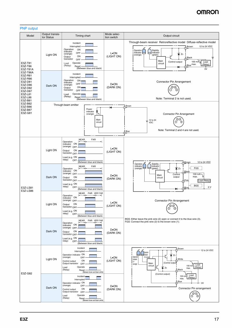
PNP output
Model Output transis-tor Status Timing chart Mode selec-
tion switch Output circuit
E3Z-T81E3Z-T86E3Z-T81AE3Z-T86AE3Z-R81E3Z-R86E3Z-D81E3Z-D86E3Z-D82E3Z-D87E3Z-L81E3Z-L86E3Z-B81E3Z-B82E3Z-B86E3Z-B87E3Z-G81
Light ON L•ON(LIGHT ON)
Dark ON D•ON(DARK ON)
E3Z-LS81E3Z-LS86
Light ON L•ON(LIGHT ON)
BGS: Either leave the pink wire (2) open or connect it to the blue wire (3).FGS: Connect the pink wire (2) to the brown wire (1).
Dark ON D•ON(DARK ON)
Light ON L•ON(LIGHT ON)
Dark ON D•ON(DARK ON)
E3Z-G82
Light ON L•ON(LIGHT ON)
Dark ON D•ON(DARK ON)
Incident
Interrupted
ON
OFF
ON
OFF
Operate
Reset(Between blue and black)
Operationindicator(orange)Outputtransistor
Load(Relay)
Through-beam receiver Retroreflective model Diffuse-reflective model
Brown
Black
Blue
Control output
Operationindicator(orange)
Stabilityindicator(green) ZD
Maincircuit
Connector Pin Arrangement
Note: Terminal 2 is not used.
4
1
3
12 to 24 VDC
100 mA max.
0V
Load(Relay)
1
2 43
Incident
Interrupted
ON
OFF
ON
OFF
Operate
Reset(Between blue and black)
Operationindicator(orange)Outputtransistor
Load(Relay)
Through-beam emitter
Powerindicator(orange)
Maincircuit
3
1
12 to 24 VDC
Brown
Blue
Connector Pin Arrangement
Note: Terminal 2 and 4 are not used.
1
2 43
ON
OFF
ON
OFF
ON
OFF
NEAR FAROperationindicator(orange)
Outputtransistor
Load (e.g.relay)
(Between blue and black)
4
1
2 43
1
2
30 V
ZD
Connector Pin Arrangement
12 to 24 VDCBrown
BlackControloutput
Blue
100 mA max.
Operationindicator(orange)
Stabilityindicator(green)
Load (Relay)
Maincircuit
Pink
FGS
BGS
ON
OFF
ON
OFF
ON
OFF
NEAR FAROperationindicator(orange)
Outputtransistor
Load (e.g.relay)
(Between blue and black)
ON
OFF
ON
OFF
ON
OFF
NEAR FAR VERY FAROperationindicator(orange)
Outputtransistor
Load (e.g.relay)
(Between blue and black)
ON
OFF
ON
OFF
ON
OFF
NEAR FAR VERY FAROperationindicator(orange)
Outputtransistor
Load (e.g.relay)
(Between blue and black)
(Between brown and black (white)
Incident
Interrupted
ON
OFF
ON
OFF
Operate
Reset
Operation indicator (orange)
Control outputOutput transistor
Load(Relay)
Connector Pin arrangement
1
2 43
12 to 24 VDC
Load(Relay)
0VBlue
100 mA max.
Load(Relay)
2
3
1Brown
White
4Black
(Control output)
ZD
100 mA max.
(Control output)
ZD
Maincircuit
OperationindicatorS 2 (orange)Operation
indicatorS 1 (orange)
(Between brown and black (white)
Incident
Interrupted
ON
OFF
ON
OFF
Operate
Reset
Operation indicator (orange)
Control outputOutput transistor
Load(Relay)
18 Photoelectric Sensors
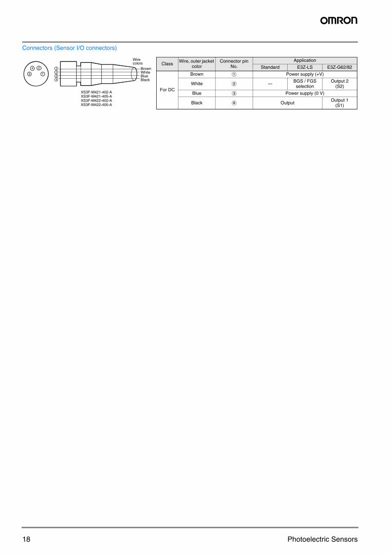
Connectors (Sensor I/O connectors)
BrownWhiteBlueBlack
Wirecolors
XS3F-M421-402-AXS3F-M421-405-AXS3F-M422-402-AXS3F-M422-405-A
24
13
1234
Class Wire, outer jacket color
Connector pin No.
Application
Standard E3Z-LS E3Z-G62/82
For DC
Brown A Power supply (+V)
White B --- BGS / FGSselection
Output 2(S2)
Blue C Power supply (0 V)
Black D Output Output 1(S1)
19E3Z
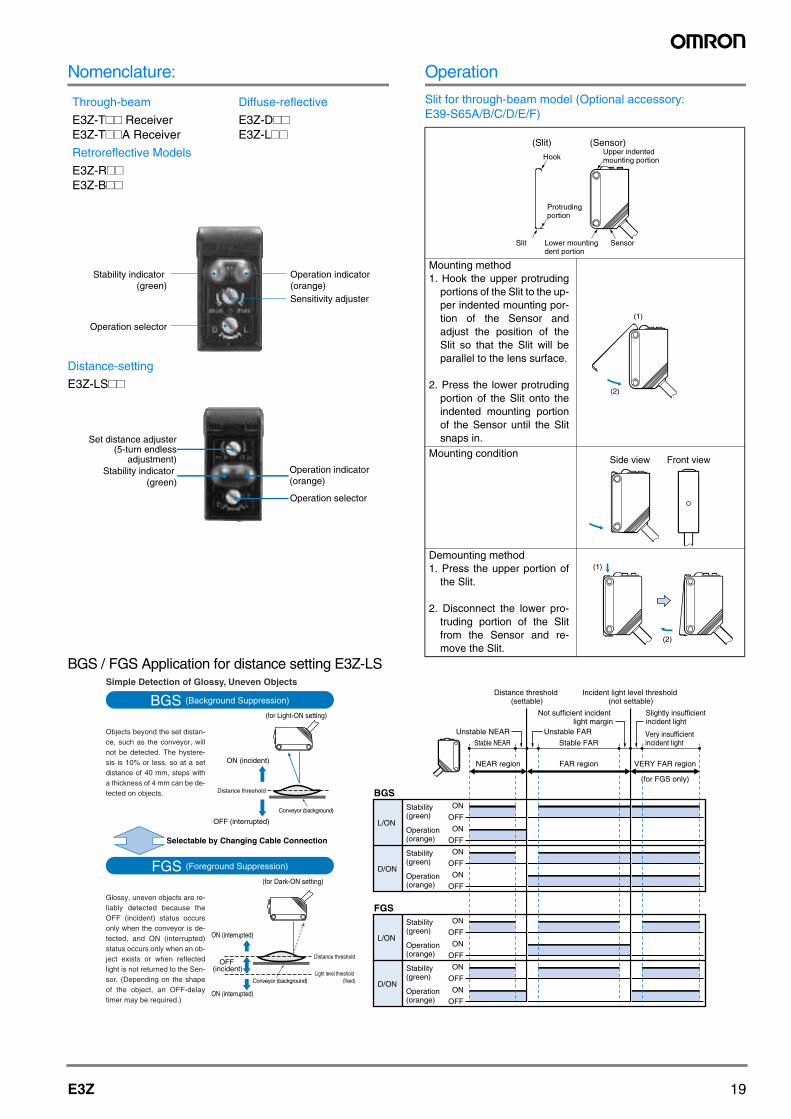
Nomenclature:
Distance-setting
E3Z-LS##
Operation
Slit for through-beam model (Optional accessory: E39-S65A/B/C/D/E/F)
BGS / FGS Application for distance setting E3Z-LS
Through-beam
E3Z-T## ReceiverE3Z-T##A Receiver
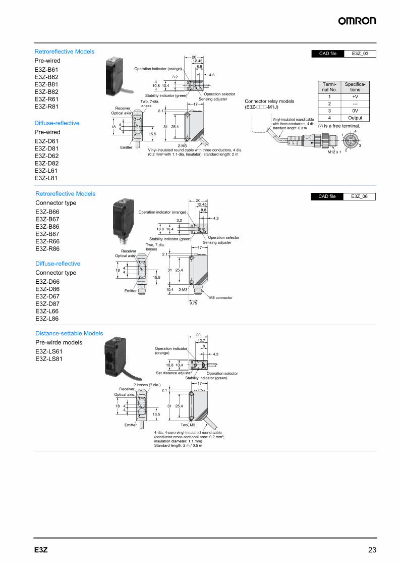
Retroreflective Models
E3Z-R##E3Z-B##
Diffuse-reflective
E3Z-D##E3Z-L##
Stability indicator (green)
Operation selector
Operation indicator (orange)Sensitivity adjuster
Stability indicator (green)
Operation selector
Operation indicator (orange)
Set distance adjuster(5-turn endless
adjustment)
Mounting method1. Hook the upper protruding
portions of the Slit to the up-per indented mounting por-tion of the Sensor andadjust the position of theSlit so that the Slit will beparallel to the lens surface.
2. Press the lower protrudingportion of the Slit onto theindented mounting portionof the Sensor until the Slitsnaps in.
Mounting condition
Demounting method1. Press the upper portion of
the Slit.
2. Disconnect the lower pro-truding portion of the Slitfrom the Sensor and re-move the Slit.
(Slit) (Sensor)Hook
Protrudingportion
Upper indented mounting portion
Lower mounting dent portion
Slit Sensor
(1)
(2)
Side view Front view
(1)
(2)
Simple Detection of Glossy, Uneven Objects
BGS (Background Suppression)
Objects beyond the set distan-ce, such as the conveyor, will not be detected. The hystere-sis is 10% or less, so at a set distance of 40 mm, steps with a thickness of 4 mm can be de-tected on objects.
Selectable by Changing Cable Connection
Distance threshold
ON (incident)
OFF (interrupted)
Conveyor (background)
(for Light-ON setting)
FGS (Foreground Suppression)
Glossy, uneven objects are re-liably detected because the OFF (incident) status occurs only when the conveyor is de-tected, and ON (interrupted) status occurs only when an ob-ject exists or when reflected light is not returned to the Sen-sor. (Depending on the shape of the object, an OFF-delay timer may be required.)
(for Dark-ON setting)
Distance threshold
Light level threshold (fixed)
ON (interrupted)
OFF(incident)
Conveyor (background)
ON (interrupted)
L/ON
Stability(green)
Stability(green)
Stability(green)
Stability(green)
L/ON
Operation(orange)
Operation(orange)
Operation(orange)
Operation(orange)
ON
OFF
ON
OFF
ON
OFF
ON
OFF
ON
OFF
ON
OFF
ON
OFF
ON
OFF
FGS
D/ON
D/ON
NEAR region
Stable NEAR Stable FARVery insufficient incident light
FAR region
Unstable NEAR Unstable FAR
VERY FAR region
(for FGS only)
Distance threshold (settable)
Incident light level threshold (not settable)
Not sufficient incident light margin
Slightly insufficient incident light
BGS
20 Photoelectric Sensors
Precautions
Do not connect an AC power supply to the Sensor. If AC pow-
er (100 VAC or more) is supplied to the Sensor, it may ex-
plode or burn.
Be sure to abide by the following precautions for the safe op-
eration of the Sensor.
WiringPower Supply Voltage and Output Load Power Supply Volt-ageMake sure that the power supply to the Sensor is within the
rated voltage range. If a voltage exceeding the rated voltage
range is supplied to the Sensor, it may explode or burn.
Load Short-circuitingDo not short-circuit the load, otherwise the Sensor may be
damaged.
Connection without LoadDo not connect the power supply to the Sensor with no load
connected, otherwise the internal elements may explode or
burn.
Operating EnvironmentDo not use the Sensor in locations with explosive or flamma-
ble gas.
DesignPower Reset TimeThe Sensor is ready to operate 100 ms after the Sensor is
turned ON. If the load and Sensor are connected to indepen-
dent power supplies respectively, be sure to turn ON the Sen-
sor before supplying power to the load.
WiringAvoiding MalfunctionsIf using the Photoelectric Sensor with an inverter or servomo-
tor, always ground the FG (frame ground) and G (ground) ter-
minals, otherwise the Sensor may malfunction.
MountingMounting the Sensor• If Sensors are mounted face-to-face, make sure that the op-
tical axes are not in opposition to each other. Otherwise,
mutual interference may result.
• Always install the Sensor carefully so that the aperture an-
gle range of the Sensor will not cause it to be directly ex-
posed to intensive light, such as sunlight, fluorescent light,
or incandescent light.
• Do not strike the Photoelectric Sensor with a hammer or
any other tool during the installation of the Sensor, or the
Sensor will lose its water-resistive properties.
• Use M3 screws to mount the Sensor.
• When mounting the case, make sure that the tightening
torque applied to each screw does not exceed 0.54 Nm.
M8 Connector• Always turn OFF the power supply to the Sensor before
connecting or disconnecting the metal connector.
• Hold the connector cover to connect or disconnect it.
• Secure the connector cover by hand. Do not use pliers, oth-
erwise the connector may be damaged.
• If the connector is not connected securely, it may be discon-
nected by vibration or the proper degree of protection of the
Sensor may not be maintained.
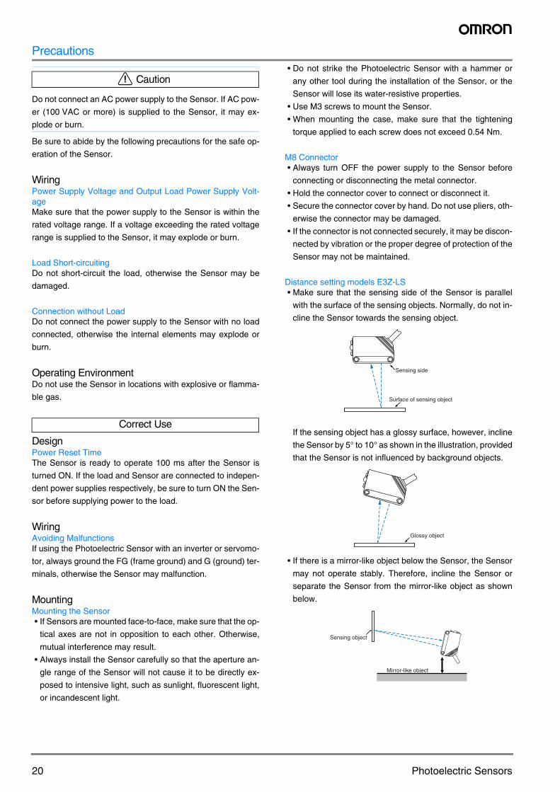
Distance setting models E3Z-LS• Make sure that the sensing side of the Sensor is parallel
with the surface of the sensing objects. Normally, do not in-
cline the Sensor towards the sensing object.
If the sensing object has a glossy surface, however, incline
the Sensor by 5° to 10° as shown in the illustration, provided
that the Sensor is not influenced by background objects.
• If there is a mirror-like object below the Sensor, the Sensor
may not operate stably. Therefore, incline the Sensor or
separate the Sensor from the mirror-like object as shown
below.
! Caution
Correct Use
Sensing side
Surface of sensing object
Glossy object
Mirror-like object
Sensing object
21E3Z
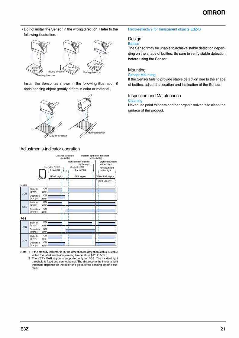
• Do not install the Sensor in the wrong direction. Refer to the
following illustration.
Install the Sensor as shown in the following illustration if
each sensing object greatly differs in color or material.
Adjustments-indicator operation
Note: 1 . If the stability indicator is lit, the detection/no detection status is stablewithin the rated ambient operating temperature (-25 to 55°C).
2 .The VERY FAR region is supported only for FGS. The incident lightthreshold is fixed and cannot be set. The distance to the incident lightthreshold depends on the color and gloss of the sensing object’s sur-face.
Retro-reflective for transparent objects E3Z-B
DesignBottlesThe Sensor may be unable to achieve stable detection depen-
ding on the shape of bottles. Be sure to verify stable detection
before using the Sensor.
MountingSensor MountingIf the Sensor fails to provide stable detection due to the shape
of bottles, adjust the location and inclination of the Sensor.
Inspection and MaintenanceCleaningNever use paint thinners or other organic solvents to clean the
surface of the product.
Moving directionMoving directionMoving direction
Sensingobject
Sensingobject
Sensingobject
Moving directionMoving direction
L/ON
Stability(green)
Stability(green)
Stability(green)
Stability(green)
L/ON
Operation(orange)
Operation(orange)
Operation(orange)
Operation(orange)
ON
OFF
ON
OFF
ON
OFF
ON
OFF
ON
OFF
ON
OFF
ON
OFF
ON
OFF
FGS
D/ON
D/ON
NEAR region
Stable NEAR Stable FARVery insufficient incident light
FAR region
Unstable NEAR Unstable FAR
VERY FAR region
(for FGS only)
Distance threshold (settable)
Incident light level threshold (not settable)
Not sufficient incident light margin
Slightly insufficient incident light
BGS
22 Photoelectric Sensors
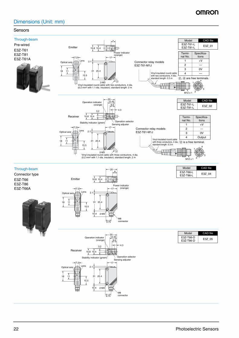
Dimensions (Unit: mm)
Sensors
Through-beam
Pre-wired
E3Z-T61E3Z-T81E3Z-T61A
8
17
2.1
25.4
Vinyl-insulated round cable with two conductors, 4 dia. (0.2 mm² with 1.1-dia. insulator); standard length: 2 m
2-M3
31
15.5
Optical axis
1118
10.410.8
Power indicator (orange)
Lens7.2
Emitter
M12 x 1
1
32
4
Vinyl-insulated round cable with two conductors, 4 dia.; standard length: 0.3 m
Terminal No. Specifications1 +V2 ---3 0V4 ---
Note: Terminal 2 and 4 are not used.
Connector relay modelsE3Z-T61-M1J
B, D are free terminals.
Termi-nal No.
Specifica-tions
1 +V
2 ---
3 0V
4 ---
Model CAD fileE3Z-T61-LE3Z-T81-L E3Z_01
M12 x 1
1
32
4
Vinyl-insulated round cable with three conductors, 4 dia.; standard length: 0.3 m
Terminal No. Specifications1 +V2 ---3 0V4 Output
Note: Terminal 2 is not used.
Connector relay modelsE3Z-T61-M1J
17
2.1
25.4
Vinyl-insulated round cable with three conductors, 4 dia. (0.2 mm² with 1.1-dia. insulator); standard length: 2 m
2-M3
31
15.5
Optical axis
1118
2012.45
8.8
3.2
Stability indicator (green)
Operation indicator (orange)
10.410.8
4.3
Sensing adjusterOperation selector
Lens7.2
Receiver
Model CAD fileE3Z-T61-LE3Z-T81-L E3Z_02
B is a free terminal.
Termi-nal No.
Specifica-tions
1 +V
2 ---
3 0V
4 Output
Through-beam
Connector type
E3Z-T66E3Z-T86E3Z-T66A 17
2.1
25.4
M8connector
31
10.4 2-M3
15.5
7.2Lens
Optical axis
1118
208
10.410.8
Power indicator (orange)
9.75
Emitter
Model CAD file
E3Z-T66-LE3Z-T86-L E3Z_04
Model CAD file
E3Z-T66-DE3Z-T86-D E3Z_05
17
2.1
25.4
M8connector9.75
31
10.4
15.5
LensOptical axis
1118
2012.45
8.8
3.2
Stability indicator (green)
Operation indicator (orange)
10.410.8
4.3
Sensing adjusterOperation selector
7.2
2-M3
Receiver
M12 x 1
1
32
4
Vinyl-insulated round cable with three conductors, 4 dia.; standard length: 0.3 m
Terminal No. Specifications1 +V2 ---3 0V4 Output
Note: Terminal 2 is not used.
Connector relay models(E3Z-###-M1J)
2012.45
8.8
3.2
Stability indicator (green)
Operation indicator (orange)
17
2.1
25.4
Vinyl-insulated round cable with three conductors, 4 dia. (0.2 mm² with 1.1-dia. insulator); standard length: 2 m
2-M3
31
15.5
Two, 7-dia. lenses
ReceiverOptical axis
Emitter
418 4
10.410.8
4.3
Sensing adjusterOperation selector
B ! "#!$
%"
#! &$
'(!
#
)*
*
+ ,(
## -(
.
.
## -(
.
.
2012.45
8.8
3.2
Stability indicator (green)
Operation indicator (orange)
17
2.1
25.4
M8 connector
31
10.4
15.5
Two, 7-dia. lensesReceiver
Optical axis
Emitter
418 4
10.410.8
4.3
Sensing adjusterOperation selector
9.75
2-M3
!#!/
"
'
'
4.3
812.7
20
10.8 10.4
17
3118 44
25.4
2.1
13.5
Operation indicator(orange)
Operation selectorSet distance adjusterStability indicator (green)
2 lenses (7 dia.)Receiver
Optical axis
Emitter Two, M3
4-dia, 4-core vinyl-insulated round cable(conductor cross-sectional area: 0.2 mm²;insulation diameter: 1.1 mm)Standard length: 2 m / 0.5 m
24 Photoelectric Sensors
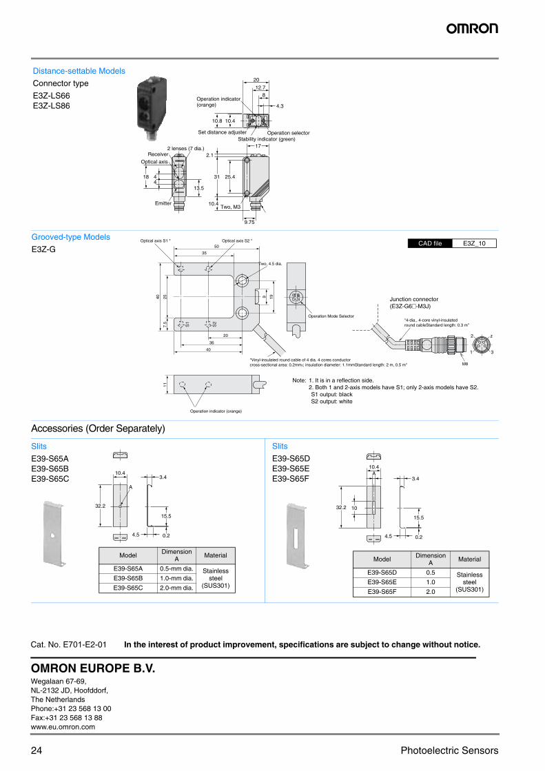
Accessories (Order Separately)
Distance-settable Models
Connector type
E3Z-LS66E3Z-LS86 4.3
812.7
20
10.8 10.4
17
31
10.4
18 44
25.4
2.1
13.5
9.75
Operation indicator(orange)
Operation selectorSet distance adjusterStability indicator (green)
2 lenses (7 dia.)Receiver
Optical axis
EmitterTwo, M3
S2
S1
Operation Mode Selector
Note: 1. It is in a reflection side.2. Both 1 and 2-axis models have S1; only 2-axis models have S2.S1 output: blackS2 output: white
36
20
40
Operation indicator (orange)
257.
511
40 199
35
50
"Vinyl-insulated round cable of 4 dia. 4 cores conductor cross-sectional area: 0.2mm2; insulation diameter: 1.1mmStandard length: 2 m, 0.5 m"
Two, 4.5 dia.
Optical axis S1 * Optical axis S2 *
"4-dia., 4-core vinyl-insulated round cableStandard length: 0.3 m"
M8
2 z
1 3
Junction connector(E3Z-G6#-M3J)
CAD file E3Z_10Grooved-type Models
E3Z-G
Slits
E39-S65AE39-S65BE39-S65C
A
32.2
4.5
3.4
0.2
15.5
10.4
E39-S65A 0.5-mm dia. Stainlesssteel
(SUS301)E39-S65B
E39-S65C
ModelDimension
A Material
1.0-mm dia.
2.0-mm dia.
Model Dimension A Material
E39-S65A 0.5-mm dia. Stainless steel
(SUS301)E39-S65B 1.0-mm dia.
E39-S65C 2.0-mm dia.
Slits
E39-S65DE39-S65EE39-S65F
A
32.2 10
4.5
3.4
0.2
15.5
10.4
E39-S65D 0.5 Stainlesssteel
(SUS301)E39-S65E
E39-S65F
ModelDimension
A Material
1.0
2.0
Model Dimension A Material
E39-S65D 0.5 Stainless steel
(SUS301)E39-S65E 1.0
E39-S65F 2.0
Cat. No. E701-E2-01 In the interest of product improvement, specifications are subject to change without notice.
OMRON EUROPE B.V.Wegalaan 67-69, NL-2132 JD, Hoofddorf,The NetherlandsPhone:+31 23 568 13 00Fax:+31 23 568 13 88www.eu.omron.com