e5063a network analyzer - xdevs.com e5063a... · network analyzer 3 caution do not exceed the...
TRANSCRIPT

E5063A Network Analyzer
Troubleshooting Guide
Agilent Technologies

Notices© Agilent Technologies, Inc. 2014
No part of this manual may be reproduced in any form or by any means (including electronic storage and retrieval or transla-tion into a foreign language) without prior agreement and written consent from Agi-lent Technologies, Inc. as governed by United States and international copyright laws.
Warranty
The material contained in this docu-ment is provided “as is,” and is sub-ject to being changed, without notice, in future editions. Further, to the max-imum extent permitted by applicable law, Agilent disclaims all warranties, either express or implied, with regard to this manual and any information contained herein, including but not limited to the implied warranties of merchantability and fitness for a par-ticular purpose. Agilent shall not be liable for errors or for incidental or consequential damages in connection with the furnishing, use, or perfor-mance of this document or of any information contained herein. Should Agilent and the user have a separate written agreement with warranty terms covering the material in this document that conflict with these terms, the warranty terms in the sep-arate agreement shall control.
Technology Licenses
The hardware and/or software described in
this document are furnished under a
license and may be used or copied only in
accordance with the terms of such license
Restricted Rights Legend
If software is for use in the performance of a U.S. Government prime contract or sub-contract, Software is delivered and licensed as “Commercial computer soft-ware” as defined in DFAR 252.227-7014 (June 1995), or as a “commercial item” as defined in FAR 2.101(a) or as “Restricted computer software” as defined in FAR 52.227-19 (June 1987) or any equivalent agency regulation or contract clause. Use, duplication or disclosure of Software is subject to Agilent Technologies’ standard commercial license terms, and non-DOD Departments and Agencies of the U.S. Gov-ernment will receive no greater than
Restricted Rights as defined in FAR 52.227-19(c)(1-2) (June 1987). U.S. Govern-ment users will receive no greater than Limited Rights as defined in FAR 52.227-14 (June 1987) or DFAR 252.227-7015 (b)(2) (November 1995), as applicable in any technical data.
Safety Notices
CAUTION
A CAUTION notice denotes a haz-ard. It calls attention to an operat-ing procedure, practice, or the like that, if not correctly performed or adhered to, could result in damage to the product or loss of important data. Do not proceed beyond a CAUTION notice until the indicated conditions are fully understood and met.
WARNING
A WARNING notice denotes a hazard. It calls attention to an operating procedure, practice, or the like that, if not correctly per-formed or adhered to, could result in personal injury or death. Do not proceed beyond a WARNING notice until the indicated condi-tions are fully understood and met.
NOTE
A NOTE notice denotes important information. It calls attention to a procedure, practice, or condition that is essential for the user to understand.
Manual Printing History
The manual’s printing date and part num-ber indicate its current edition. The printing date changes when a new edition is printed (minor corrections and updates that are incorporated at reprint do not cause the date to change). The manual part number changes when extensive technical changes are incorporated.
April 2014 First Edition
Manual Part Number
E5063-90100
Edition
First edition, April 2014
Printed in Malaysia
Agilent Technologies, Inc. 5301 Stevens Creek Blvd Santa Clara, CA 95051 USA
.

Caution
Network Analyzer
Do not exceed the operating input power, voltage, and current level and signal type appropriate for the
instrument being used, refer to your instrument's Function Reference.
Electrostatic discharge (ESD) can damage the highly sensitive microcircuits in your instrument. ESD damage is most likely to occur as the test fixtures are being connected or disconnected. Protect them from ESD damage by wearing a grounding strap that provides a high resistance path to ground. Alternatively, ground yourself to discharge any static charge built- up by touching the outer shell of any grounded instrument chassis before touching the test port connectors.
3

Safety Summary
4
When you notice any of the unusual conditions listed below, immediately terminate operation and disconnect the power cable.
Contact your local Agilent Technologies sales representative or authorized service company for repair of the instrument. If you continue to operate without repairing the instrument, there is a potential fire or shock hazard to the operator.
• Instrument operates abnormally.
• Instrument emits abnormal noise, smell, smoke or a spark- like light during operation.
• Instrument generates high temperature or electrical shock during operation.
• Power cable, plug, or receptacle on instrument is damaged.
• Foreign substance or liquid has fallen into the instrument.
Network Analyzer

Manufacturer’s Declaration
Network Analyzer
Herstellerbescheinigung
GERA- USCHEMISSION
LpA < 70 dB
am Arbeitsplatz
normaler Betrieb
nach DIN 45635 T. 19
Manufacturer's Declaration
ACOUSTIC NOISE EMISSION
LpA < 70 dB
operator position
normal operation
per ISO 7779
5

Regulatory Compliance Information
6
This product complies with the essential requirements of the following applicable European Directives, and carries the CE marking accordingly:
• The Low Voltage Directive 2006/95/EC
• The EMC Directive 2004/108/EEC
To obtain Declaration of Conformity, please contact your local Agilent Technologies sales office, agent or distributor.
Network Analyzer

Safety Notice Supplement
Network Analyzer
• This equipment complies with EN/IEC61010- 1:2001.
• This equipment is of MEASUREMENT CATEGORY I (CAT I). Do not use for CAT II, III, or IV.
• Do not connect the measuring terminals to mains.
• This equipment is a POLLUTION DEGREE 2, INDOOR USE product.
• This equipment is tested in stand- alone condition and in combination with the accessories supplied by Agilent Technologies against the requirement of the standards described in the Declaration of Conformity. If it is used as a system component, compliance of related regulations and safety requirements are to be confirmed by the builder of the system.
7

General Safety Precautions
8
The following general safety precautions must be observed during all phases of operation, service, and repair of this instrument. Failure to comply with these precautions or with specific WARNINGS elsewhere in this manual may impair the protection provided by the equipment. Such noncompliance would also violate safety standards of design, manufacture, and intended use of the instrument. Agilent Technologies assumes no liability for the customer’s failure to comply with these precautions.
NOTE The E5093A complies with INSTALLATION CATEGORY II as well as POLLUTION DEGREE 2 in IEC61010-1. The E5093A is an INDOOR USE product.
NOTE The LEDs in the E5093A are Class 1 in accordance with IEC60825-1, CLASS 1 LED PRODUCT.
• Ground the Instrument
To avoid electric shock, the instrument chassis and cabinet must be grounded with the supplied power cable’s grounding prong.
• DO NOT Operate in an Explosive Atmosphere
Do not operate the instrument in the presence of inflammable gasses or fumes. Operation of any electrical instrument in such an environment clearly constitutes a safety hazard.
• Keep Away from Live Circuits
Operators must not remove instrument covers. Component replacement and internal adjustments must be made by qualified maintenance personnel. Do not replace components with the power cable connected. Under certain conditions, dangerous voltage levels may remain even after the power cable has been disconnected. To avoid injuries, always disconnect the power and discharge circuits before touching them.
• DO NOT Service or Adjust the Instrument Alone
Do not attempt internal service or adjustment unless another person, capable of rendering first aid and resuscitation, is present.
• DO NOT Substitute Parts or Modify the Instrument
Network Analyzer

Network Analyzer
To avoid the danger of introducing additional hazards, do not install substitute parts or perform unauthorized modifications to the instrument. Return the instrument to an Agilent Technologies Sales and Service Office for service and repair to ensure that safety features are maintained in operational condition.
• Dangerous Procedure Warnings
Warnings, such as the example below, precede potentially dangerous procedures throughout this manual. Instructions contained in the warnings must be followed.
WARNING Dangerous voltage levels, capable of causing death, are present in this instrument. Use extreme caution when handling, testing, and adjusting this instrument.
9

Safety Symbols
10
General definitions of safety symbols used on the instrument or in manuals are listed below.
Instruction Manual symbol: the product is marked with this symbol when it is necessary for the user to refer to the instrument manual.
Alternating current.
Direct current.
On (Supply).
Off (Supply).
In- position of push- button switch.
Out- position of push- button switch.
A chassis terminal; a connection to the instrument’s chassis, which includes all exposed metal structure.
Standby.
Network Analyzer
Network Analyzer
Certification
Agilent Technologies certifies that this product met its published specifications at the time of shipment from the factory. Agilent Technologies further certifies that its calibration measurements are traceable to the United States National Institute of Standards and Technology, to the extent allowed by the Institution’s calibration facility or by the calibration facilities of other International Standards Organization members.
Documentation Warranty
The material contained in this document is provided "as is," and is subject to being changed, without notice, in future editions. Further, to the maximum extent permitted by applicable law, Agilent disclaims all warranties, either express or implied with regard to this manual and any information contained herein, including but not limited to the implied warranties of merchantability and fitness for a particular purpose. Agilent shall not be liable for errors or for incidental or consequential damages in connection with the furnishing, use, or performance of this document or any information contained herein. Should Agilent and the user have a separate written agreement with warranty terms covering the material in this document that conflict with these terms, the warranty terms in the separate agreement will control.
Exclusive Remedies
The remedies provided herein are Buyer’s sole and exclusive remedies. Agilent Technologies shall not be liable for any direct, indirect, special, incidental, or consequential damages, whether based on contract, tort, or any other legal theory.
Assistance
Product maintenance agreements and other customer assistance agreements are available for Agilent Technologies products.
For any assistance, contact your nearest Agilent Technologies Sales and Service Office. Addresses are provided at the back of this manual.
11

Manuals for E5063A
12
Agilent provides the following three manuals for E5063A. The latest version of all documentations can be downloaded from http://www.agilent.com/find/e5063a- manual.
Installation Guide
The installation guide provides start up setup information when you use the E5063A for the first time, system recovery procedures and troubleshooting information when Windows cannot boot up. See this manual first when you use the E5063A for the first time.
Troubleshooting Guide
The troubleshooting guide (this manual) provides troubleshooting information when operational problems are encountered on the E5063A. See this manual when you need to troubleshoot the E5063A.
Online Help
The online help provides the information about the quick start, measurement operation, programming, built- in VBA, I/O interface and error messages. This is pre- installed in the E5063A. Press the [Help] hard key on the front panel to open. Quick Start helps in understanding the E5063A operation quickly.
The latest version of online help is available at: http://ena.tm.agilent.com/e5063a/manuals/webhelp/eng/
The online help has context sensitive help, which is a great feature of the E5063A help. It allows you to get information about the selected softkey by pressing the Help key in the E5063A or by pressing F1 in a keyboard attached to the E5063A or by clicking the help button in a dialog box. With context sensitive help, users can receive information quickly about the area the user is working in the firmware of the E5063A. It provides information relevant to the task that needs to be accomplished and reduces the time to search relevant information required to complete a task.
Network Analyzer
In This Guide...
Network Analyzer
The following shows the contents of this manual.
Chapter 1, "Troubleshooting"
This chapter provides the procedure to isolate a faulty assembly in the E5063A.
Chapter 2, "Post Repair Procedure"
This chapter lists the procedures required to verify the E5063A operation after an assembly is replaced with a new one.
13

14
Network Analyzer
ContentsRegulatory Compliance Information 6
Safety Notice Supplement 7
1 Troubleshooting
Introduction 4
How to exit from the E5063A Measurement View 5
To Troubleshoot the Instrument 6
Primary Trouble Isolation 6
No Display Troubleshooting 8
Booting Process Troubleshooting 13
Troubleshooting Using Diagnostic Test 18
Diagnostic Test 18Diagnostic Test Failure Troubleshooting 20
Function Specific Troubleshooting 21
To Check the Front Panel 22To Check the Touch Panel 23To Check the LCD 24To Check the External Keyboard 24To Check the Mouse 25To Check the External Monitor Output Port 25To Check the External Trigger Input 25To Check the GPIB 26To Check the USB 26
Performance Test failure Troubleshooting 27
Recommended Adjustment for Performance Test failure 27Adjustment failure Troubleshooting 29Performance Test failure Troubleshooting 29
2 Post Repair Procedure
Post Repair Procedures 32
License file 32
Regional Sales and Support Offices
Network Analyzer 1

2 Network Analyzer

E5063A Network Analyzer Troubleshooting Guide
1Troubleshooting
Introduction 4
How to exit from the E5063A Measurement View 5
To Troubleshoot the Instrument 6
No Display Troubleshooting 8
Booting Process Troubleshooting 13
Troubleshooting Using Diagnostic Test 18
Function Specific Troubleshooting 21
Performance Test failure Troubleshooting 27
This chapter provides the procedure to isolate a faulty assembly in the E5063A.
3Agilent Technologies

1 Troubleshooting
Introduction
4
WARNING These servicing instructions are for use by qualified personnel only. To avoid possible electrical shock, do not perform any servicing unless you are qualified to do so.
WARNING The opening of covers or removal of parts are likely to expose dangerous voltages. Disconnect the instrument from its power supply beforehand.
CAUTION Many of the assemblies in the instrument are very susceptible to damage from ESD (electrostatic discharge). Perform the following procedures only at a static-safe workstation and wear a grounding strap.
CAUTION DO NOT operate without following instructions. Program or files in the instrument may be broken.
Network Analyzer

Troubleshooting 1
How to exit from the E5063A Measurement View
Network Analyzer
Some troubleshooting procedures require you to exit from the E5063A Measurement View. The following procedure describes the steps to to exit from the E5063A Measurement View.
Step 1. Connect a mouse to the connectors on the E5063A rear panel.
Step 2. Turn the instrument on.
Step 3. Press key.
Step 4. Click Service.
Step 5. Click Exit.
Step 6. Click Yes in Exit menu. The E5063A exits from Measurement View to Windows desktop.
Figure 1 Exit dialog box
NOTE If you want to return to the Measurement View, double-click the” E5063A” icon on the desktop.
NOTE if you need to shut down the E5063A, press the standby switch on the front panel.
5

1 Troubleshooting
To Troubleshoot the Instrument
6
This section describes the basic troubleshooting procedural flow when servicing the E5063A. The primary procedural tool in this section is the flowchart. The flowchart contains the entire troubleshooting path from the failure symptom to the isolation of faulty assembly, and will direct you through the repair in an orderly manner through the possible failure symptoms. Reference letters (Yes/No) on the flowchart point to procedural steps that briefly explain the next troubleshooting method to be performed.
Primary Trouble Isolation
The primary trouble isolation procedure can be performed without disassembling the E5063A. Figure 2 shows the trouble isolation flow chart.
Step 1. Turn the instrument power on.
A few minutes after the E5063A is turned on, the measurement view is displayed on the screen. The display screen should be similar to Figure 11, “E5063A application,” on page 17.
Step 2. Check the display.
• If no display appears on the LCD after the E5063A is turned on, go to “No Display Troubleshooting" on page 8.
• If the E5063A stops during booting process despite something being displayed on the LCD, go to “Booting Process Troubleshooting" on page 13.
Step 3. Check the basic function.
If the front- panel/keyboard/mouse controls, LCD display, data storage, remote interface or other function (except the measurement function) does not work correctly, go to “Function Specific Troubleshooting" on page 21.
Step 4. Check the measurement function.
If the instrument fails performance test, go to “Performance Test failure Troubleshooting" on page 27.
If the measurement function does not work correctly, perform the diagnostic tests provided in the E5063A’s service function. If the diagnostic tests fail, go to “Troubleshooting Using Diagnostic Test" on page 18.
Network Analyzer

Troubleshooting 1
Network Analyzer
Figure 2 Primary trouble isolation flowchart
7

1 Troubleshooting
No Display Troubleshooting
8
If the E5063A displays nothing despite being powered from proper ac power line, isolate the failure in accordance with the procedure shown in Figure 3.
Connect the keyboard to the E5063A rear panel connector and start trouble isolation. The methods of trouble isolation are described in the procedural step 1 to 6.
Network Analyzer

Troubleshooting 1
Network Analyzer
Figure 3 No display trouble isolation procedure
9

10
1 Troubleshooting
Step 1. Check fan operation and DC monitor LED.
If the rear panel fan (blower) doesn’t run, a failure in power supply is assumed. Remove the E5063A outer cover and check if the following LEDs light:
• +3.3 V and +5 V DC monitor LEDs on A60 CPU module as shown in Figure 4.
• LEDs on A51 DSP module as shown in Figure 5.
Figure 4 LEDs on CPU module
Figure 5 LEDs on DSP module
Network Analyzer

Troubleshooting 1
Network Analyzer
Step 2. Check system fan inside.
If the system fan, located on the left side of the chassis inside the E5063A, does not run, the problem seems to be in the A51 DSP board or the flat cable between the A51 DSP board and A60 CPU module. In this case, remove the E5063A outer cover and determine if the fan runs or not.
If a beep and power shutdown occurs immediately after the power is turned on, there is a possibility that the fan would not run. The power shutdown occurs the moment the system fan stops by any anomaly. In this case, check the fan.
If the power shutdown occurs without a beep, the problem seems to be with the A51 DSP board or the A60 CPU module.
Step 3. Check LED of “Num Lock” key.
Press the Num Lock key on the keyboard. If the LED on the keyboard does not light as shown in Figure 6, a problem seems to be in the A60 CPU module.
Check the following before replacing the A60 CPU module.
• Connections to the A60 CPU Module are normal
• There are no disconnections or loose connections
Figure 6 LED of the Num Lock key
11

12
1 Troubleshooting
Step 4. Check the external monitor
Connect an external VGA monitor to the External Monitor Output Port on the E5063A rear panel.
• If something is displayed on the external monitor, the problem seems to be related to the LCD display. Also, check the A52 Front Panel I/F board because the ON/OFF setting of the LCD backlight is controlled by the A52 Front Panel I/F board.
• If nothing is displayed even on the external monitor, the problems seems to be in the A60 CPU module.
Step 5. Check the flat cable
Check the flat cable between the A60 CPU Module and A52 Front Panel I/F board.
Step 6. Check around the backlight
Check the inverter board and the cable between the inverter board and A52 Front Panel I/F board. Also check the cables between the LCD and A52 Front Panel I/F board. If the cables are normal, check the LCD display.
Network Analyzer

Troubleshooting 1
Booting Process Troubleshooting
Network Analyzer
Figure 7 represents the booting process flow in the E5063A. If the E5063A stops in the booting process, troubleshoot using the following step- by- step procedure.
Figure 7 Booting process flowchart
13

14
1 Troubleshooting
Step 1. Splash Screen.
The splash screen is displayed with Agilent logo as shown in Figure 8.
If the splash screen is displayed, you can assume that the A60 CPU Module is functioning correctly.
NOTE While the splash screen is displayed, if you want to run the BIOS setup utility, push F2 key on the attached external keyboard as soon as you see the splash screen. The password to enter BIOS setup utility is agt0nly (0 is Zero).
Changing BIOS setting may cause malfunction or lower performance of the instrument.
Step 2. Boot up Screen.
The boot up screen is displayed as shown in Figure 9.
If no selection is made, the system will continue the boot up process after 3 seconds.
Figure 8 Splash Screen
NOTE While the Boot up screen is displayed, if you want to perform system recovery, select Agilent Recovery System as soon as the Windows Boot Manager screen is displayed. For details of the system recovery, refer to the Installation Guide.
Network Analyzer

Troubleshooting 1
Network Analyzer
Step 3. Windows boot screen.
The Windows boot screen is displayed as shown in Figure 10. If the Windows boot screen is displayed, it is assumed that the HDD works and the Windows operating system is starting up.
Figure 9 Boot up Screen
Figure 10 Windows boot screens
15

16
1 Troubleshooting
If you encounter the following problems, try to execute the system recovery before replacing the HDD.
• “xxx file is missing” message is displayed on DOS screen.
• The window boot screen is not displayed after the splash screen.
• Windows always boots up in Safe Mode.
NOTE If the E5063A was turned off without proper shutdown process, Microsoft Scandisk runs while the windows boot screens are displayed. If a serious problem is found during the scan, execute the system recovery. For details on executing the system recovery, refer to the Installation Guide. If the operating system still does not boot up properly after reinstallation, replace the HDD.
NOTE The operating system automatically checks the device drivers which are necessary for use in the E5063A and are installed in the system before the E5063A is shipped from Agilent factory. If the operating system does not detect them, a message box is displayed. In this case, install the device driver.
Step 4. System Initialization Screen.
The system initialization screen is displayed. If the display whites out, is entirely blue or a dialog box appears, a mass storage problem is suspected. Try to perform the mass storage recovery procedure.
NOTE If the message “Will Shut Down in Five Seconds” is displayed and shutdown occurs, the A51 DSP board has failed to start up. The following messages may be displayed before the shutdown occurs:
“Fatal Error: Failed to Initialize DSP Driver”
or “Fatal Error: Failed to Initialize DSP”
This message indicates that the DSP board does not work or is not properly connected to the DSP DSP board.
“Fatal Error: Failed to Update DSP Code”
If this happens, the DSP board has failed to write the DSP program into the flash ROM when the firmware was first installed or after being updated to the latest version. A problem with the A51 DSP board or A60 CPU Module is suspected.
Network Analyzer

Troubleshooting 1
Network Analyzer
Step 5. E5063A Application view.
The E5063A application is executed as shown in Figure 11 after the system initialization is completed without problem.
Figure 11 E5063A application
17

1 Troubleshooting
Troubleshooting Using Diagnostic Test
18
The E5063A has diagnostic test function to diagnose the analog measurement section and internal dc power supply voltages. The diagnostic tests make it possible to isolate a faulty board assembly. The following paragraphs describe the procedure to perform the diagnostic tests.
Diagnostic Test
To execute the diagnostic test
To isolate faulty board assembly modules, execute the diagnostic test in accordance with the following procedure.
NOTE To perform the diagnostic test properly, the following conditions must be met:
Environmental temperature: 23°C ±5°C
Warm up time: > 30 minutes
NOTE Do not operate front panel keys, keyboard and mouse during the diagnostic test. Changing the instrument setting while the diagnostic test is in progress will cause incorrect test results.
Step 1. Press key.
Step 2. Click Service Menu > Test Menu > Diagnostic Test.
Network Analyzer

Troubleshooting 1
Network Analyzer
Step 3. Select Execute All.
Figure 12 Diagnostic Test 1/3
Figure 13 Diagnostic Test 2/3
19

20
1 Troubleshooting
Follow the instruction for connection, then click OK to execute the test.
Step 4. Click Exit to exit the diagnostic test.
Figure 14 Diagnostic Test 3/3
Diagnostic Test Failure Troubleshooting
Replace the A1 Analog Module when any test in diagnostic test is failed as the A1 module is only one analog board which include both source and receiver in the E5063A.
Network Analyzer

Troubleshooting 1
Function Specific Troubleshooting
Network Analyzer
If the E5063A exhibits a failure symptom that is related to a specific function or control such as a front panel key control, data storage, remote control interface, external trigger, external keyboard or mouse, isolate the trouble using the Function Specific Troubleshooting procedures described below. The major functions of the E5063A and the troubleshooting procedure for each function are shown in Table 1.
Table 1 Major functions and troubleshooting procedures
Function Description Troubleshooting
Front panel keys All E5063A functions can be set and controlled via the front panel keys.
Refer to “To Check the Front Panel" on page 22
Touch panel The touch screen display on the E5063A allows all functions in the menu bars, setup windows and dialog boxes to be set by a touch to the screen panel.
Refer to “To Check the Touch Panel" on page 23
LCD display Almost all the information including the measurement value, setup state, result data processing, menu bar, softkey label and others are indicated on the 10.4- inch color LCD display.
Refer to “To Check the LCD" on page 24
External keyboard The external keyboard can be used for the entry of numerical and character data when it is connected to the USB connector on the front or rear panel.
Refer to “To Check the External Keyboard" on page 24
Mouse The mouse can be used to move the pointer on the LCD display, select functions and change settings, when it is connected to the USB connected on the front or rear panel.
Refer to “To Check the Mouse" on page 25
External monitor An external color monitor can be used to display the same information as the E5063A LCD display, when it is connected to the External Monitor Output Port (15- pin VGA connector) on the rear panel.
Refer to “To Check the External Monitor Output Port" on page 25
21

1 Troubleshooting
To Check the Front Panel
GPIB Interface The GPIB compatibility allows the E5063A to be operated as a talker/listener on IEEE 488 interface bus.
Refer to “To Check the GPIB" on page 26
Handler Interface The Handler Interface port can be used to transfer comparator decision output data and perform timing synchronization with an external handler.
Refer to “To execute the diagnostic test" on page 18 and “To execute the diagnostic test" on page 18
Table 1 Major functions and troubleshooting procedures
22
Procedure
Step 1. Press key.
Step 2. Click Service Menu - Test Menu - Front Panel. This opens the Front Panel Test window as shown in Figure 15.
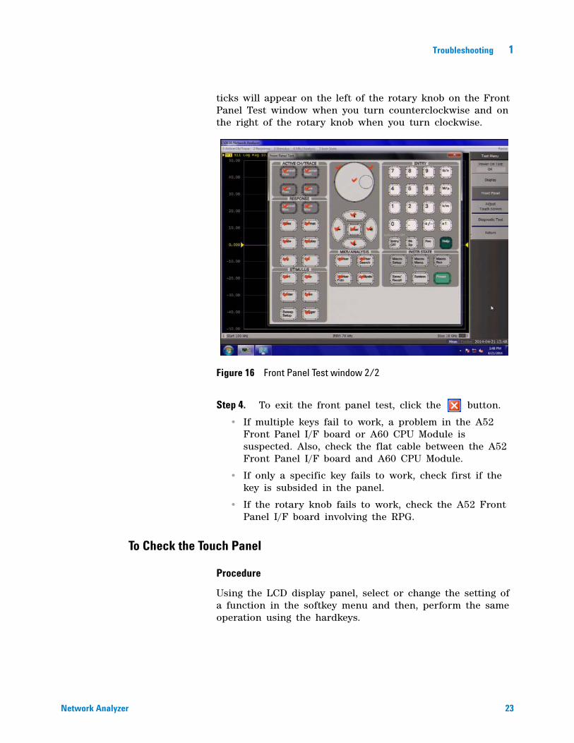
Step 3. Press the front panel keys. Red ticks will appear on the Front Panel Test window whenever the corresponding key on the front panel is pressed as shown in Figure 16. Turn the rotary knob clockwise or counterclockwise. Red
Figure 15 Front Panel Test window 1/2
Network Analyzer
Troubleshooting 1
Network Analyzer
ticks will appear on the left of the rotary knob on the Front Panel Test window when you turn counterclockwise and on the right of the rotary knob when you turn clockwise.
Step 4. To exit the front panel test, click the button.
• If multiple keys fail to work, a problem in the A52 Front Panel I/F board or A60 CPU Module is suspected. Also, check the flat cable between the A52 Front Panel I/F board and A60 CPU Module.
• If only a specific key fails to work, check first if the key is subsided in the panel.
• If the rotary knob fails to work, check the A52 Front Panel I/F board involving the RPG.
Figure 16 Front Panel Test window 2/2
To Check the Touch Panel
Procedure
Using the LCD display panel, select or change the setting of a function in the softkey menu and then, perform the same operation using the hardkeys.
23

24
1 Troubleshooting
• If the touch panel does not work correctly when the hardkeys function normally, a failure seems to be in the touch screen controller assembly or touch- panel LCD assembly. (The touch panel is not replaceable independently of the LCD.)
• Check the cable between the touch screen controller and the serial interface connector on the A60 CPU module.
• If no problem is found in the above checks, a failure in the A60 CPU Module is suspected.
To Check the LCD
Procedure
Step 1. Press key.
Step 2. Click Service - Display Test. The whole LCD screen turns RED.
Step 3. Tap anywhere on the LCD to go through the color test screen of RED, GREEN, BLUE, WHITE and BLACK. You can also use the rotary knob turned clockwise or press the ENTRY keys on the E5063A front panel.
If the color test screen does not appear, perform Step 4.
Step 3. Connect an external VGA monitor to the External Monitor Output Port on the E5063A rear panel.
• If the monitor screen view is the same as the LCD display, the problem seems to be in the A60 CPU module.
• If only the LCD display has a problem, check the flat cable between the A52 Front Panel I/F board and A60 CPU Module.
• If the cables are normal, check the A51 LCD module.
To Check the External Keyboard
Procedure
Step 1. Connect an external keyboard to the E5063A rear panel USB port.
Step 2. Press key.
Network Analyzer

Troubleshooting 1
Network Analyzer
Step 3. Press and keys on the external keyboard, and verify that the cursor on the menu bar moves up and down. If it doesn’t work, the external keyboard or the A60 CPU Module may be faulty.
To Check the Mouse
Procedure
Step 1. Connect a mouse to the E5063A rear panel USB port.
Step 2. Verify that the mouse buttons work normally. If any button does not work or the mouse pointer does not move, a failure in the mouse or the A60 CPU Module is suspected.
To Check the External Monitor Output Port
Procedure
Step 1. Connect an external VGA color monitor to the External Monitor Output Port on the E5063A rear panel.
Step 2. Turn the external monitor on.
Step 3. Verify that the monitor screen view is the same as the display on the LCD. If the monitor screen view is abnormal, a failure seems to be in the A60 CPU module.
To Check the External Trigger Input
Procedure
Step 1. Press key.
Step 2. Press Trigger Mode key.
Step 3. Click External in the menu bar to set the trigger mode to External.
Step 4. Connect a BNC Short or 50 ohm termination to the External Trigger Input Port on the rear panel and disconnect it. A measurement trigger should be generated and a measurement result should be refreshed.
Step 5. If no trigger occurs, a failure in the A51 DSP board is suspected.
25

1 Troubleshooting
To Check the GPIB
26
Procedure
Perform the E5063A Performance Test program. If the controller cannot detect the E5063A, the problem seems to be in the A60 CPU module.
To Check the USB
Procedure
Connect a USB cable between controller PC and USB Interface port (USBTMC) on the rear panel of the E5063A. Turn the controller PC on. If the E5063A cannot detect the controller PC, the problems seems to be in the CPU module. Agilent I/O Library should be installed on the PC.
Network Analyzer

Troubleshooting 1
Performance Test failure Troubleshooting
Network Analyzer
This section describes the adjustment and troubleshooting procedures used when the E5063A fails the performance tests. If the performance of the instrument is critical for the test limits and seems adjustable, perform first the adjustment(s) related to the failed test. When the test result are far from the tolerance of the test or the performance is not adjustable, isolate the faulty assembly in accordance with the “Performance Test failure Troubleshooting procedure.
Recommended Adjustment for Performance Test failure
Table 2 shows the recommended adjustments when the performance test fails. Select the adjustment program corresponding to the recommended adjustment and perform the adjustment.
You can execute the adjustment for Option 2H5 only. When the performance test fails on the unit with option 245 or 285, replace A1 board.
Table 2 Recommended adjustment for performance test failure
Failed Performance test item Recommended Adjusment
Frequency Accuracy PLL Sub-bandReference Frequency
RF Output Level Accuracy Test PLL Sub-bandReference FrequencySource Max. Output Power CheckSynthesizer GainSource Output Power
RF Output Level Linearity Test PLL Sub-bandReference FrequencySource Max. Output Power CheckSynthesizer GainSource Output Power
27

28
1 Troubleshooting
Crosstalk & System Dynamic Range Test
PLL Sub-bandReference FrequencySource Max. Output Power CheckMixer Local Input LevelSynthesizer GainReceiver IF FlatnessSource Output PowerReceiver IF Range Receiver Port CharacteristicsVirtual Bridge CoefficientReceiver Absolute Gain
Trace Noise Test PLL Sub-bandReference FrequencySource Max. Output Power CheckMixer Local Input LevelSynthesizer GainReceiver IF FlatnessSource Output PowerReceiver IF Range Receiver Port CharacteristicsVirtual Bridge CoefficientReceiver Absolute Gain
Uncorrected System Performance Test PLL Sub-bandReference FrequencySource Max. Output Power CheckMixer Local Input LevelSynthesizer GainReceiver IF FlatnessSource Output PowerReceiver IF Range Receiver Port CharacteristicsVirtual Bridge CoefficientReceiver Absolute Gain
Dynamic Accuracy Test(1) PLL Sub-bandReference FrequencyMixer Local Input LevelReceiver IF FlatnessReceiver IF Range Receiver Port CharacteristicsVirtual Bridge CoefficientReceiver Absolute Gain
Table 2 Recommended adjustment for performance test failure
Network Analyzer

Troubleshooting 1
Network Analyzer
Dynamic Accuracy Test(2) PLL Sub-bandReference FrequencyMixer Local Input LevelReceiver IF FlatnessReceiver IF Range Receiver Port CharacteristicsVirtual Bridge CoefficientReceiver Absolute Gain
Noise Floor PLL Sub-bandReference FrequencySource Max. Output Power CheckMixer Local Input LevelSynthesizer GainReceiver IF FlatnessReceiver IF Range Receiver Port CharacteristicsVirtual Bridge CoefficientReceiver Absolute Gain
Table 2 Recommended adjustment for performance test failure
Adjustment failure Troubleshooting
Replace the A1 Analog Module when any adjustment in diagnostic test is failed as the A1 module is only analog board which includes both source and receiver in the E5063A.
Performance Test failure Troubleshooting
Replace the A1 Analog Module when any adjustment in diagnostic test is failed as the A1 module is only one analog board which includes both source and receiver in the E5063A.
29

30
1 Troubleshooting
Network Analyzer

E5063A Network AnalyzerInstallation Guide
2Post Repair Procedure
Post Repair Procedures 32
This chapter lists the procedures required to verify the E5063A operation after an assembly is replaced with a new one.
31Agilent Technologies

2 Post Repair Procedure
Post Repair Procedures
32
Table 3 lists the required procedures that must be performed after the replacement of an assembly. These are the recommended minimum procedures to ensure that the replacement is successfully completed.
License file
Table 3 Post Repair Procedures
Replaced Assembly or Part
Required Adjustment Correction Constants (CC)
Verification
A11 Source Board When you replace defective board with E5063-63001 or E5063-69001, it is not necessary to performing the adjustment. The boards are adjusted at factory. Correction Constant data is stored in A11 itself and uploaded to SSD automatically.
Troubleshooting Using Diagnostic Test 18Perform all of the Performance Test.
A51 DSP Board Perform the following required adjustments using “A51 DSP Board” in Spot Adjustment of the program.
Troubleshooting Using Diagnostic Test 18Inspect the Booting Process
SSD (Solid State Drive)
Perform the following required adjustments using “HDD” in Spot Adjustment in the program. Copy from license file (.lic) under E:/license
Inspect the Booting Process
The license code for the frequency option (either 245, 285 or 2H5) and generation ID (G01) must be installed in E:/license, or the error message will be displayed.
The license code can be downloaded from the Agilent Software Manager (ASM) or Agilent Software Licensing (ASL).
Network Analyzer

Regional Sales and Support Offices
For more information about Agilent Technologies test and measurement products, applications,
services, and for the current sales office listing, visit our web site: http://www.agilent.com/find/tmdir.
You can also contact one of the following centers and ask for a test and measurement sales
representative*1.
United States:Test and Measurement Call Center(tel) 1 800 452-4844(fax) 1 888 900-8921
Australia/New Zealand:(tel) (61 3) 9210-5555 (Australia)(fax) (61 3) 9210-5899(tel) (64 4) 939-0636 (New Zealand)(fax) (64 4) 972-5364
Canada:Test and Measurement Call Center(tel) 1 877 894-4414(fax) 1 888 900-8921
Asia Pacific:(tel) (65) 6375-8100(fax) (65) 6836-0252E-mail: [email protected]
China:(tel) 800 810-0189(fax) 800 820-2816Europe:(tel) (31 20) 547-2323(fax) (31 20) 547-2390Japan:Call Center(tel) 0120 421-345(tel) (81) 426 56-7832(fax) (81) 426 56-7840Korea:(tel) (82 2) 2004-5004(fax) (82 2) 2004-5115Latin America:(tel) (305) 269-7500(fax) (305) 269-7599Taiwan:(tel) 0800 047 866(fax) 0800 286 331
33Agilent Technologies
* 1. As of 21/01/04

34
Network Analyzer

www.agilent.com
© Agilent Technologies, Inc. 2014
Printed in MalaysiaFirst edition, April 2014
*E5063-90100*E5063-90100
Agilent Technologies