e5080b method of implementation (moi) for 100base-tx
TRANSCRIPT
Find us at www.keysight.com Page 1
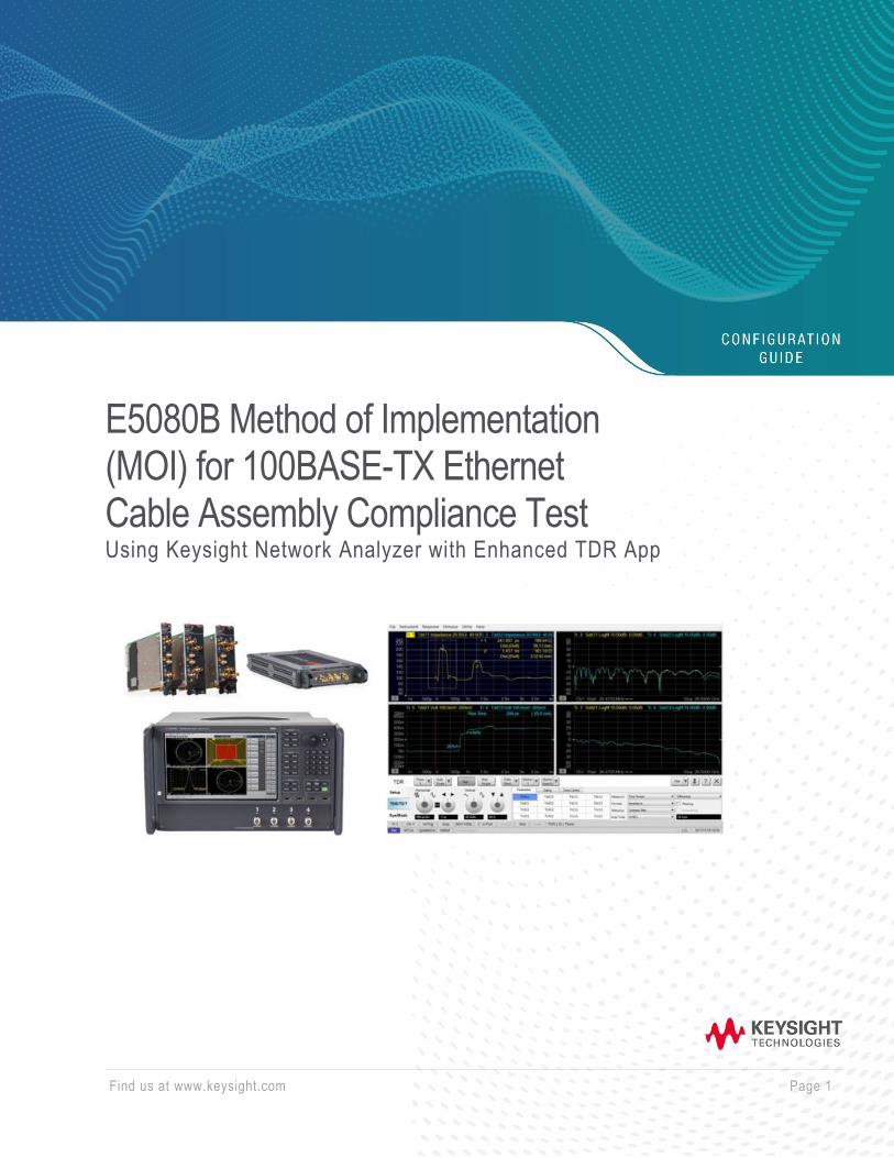
E5080B Method of Implementation (MOI) for 100BASE-TX Ethernet Cable Assembly Compliance Test Using Keysight Network Analyzer with Enhanced TDR App
Find us at www.keysight.com Page 2
Table of Contents
1. Revision History ........................................................................................................................................ 3
2. Configuration Requirements ..................................................................................................................... 3
3. Test Procedure .......................................................................................................................................... 4
3.1 Test Flow Chart ....................................................................................................................................... 4
3.2 Description of Measurement Window ..................................................................................................... 4
4. Measurement Setups ................................................................................................................................ 5
4.1 Recalling a State File .............................................................................................................................. 5
4.2 Calibration Setup ..................................................................................................................................... 7
4.2.1. ECal Calibration and Fixture Compensation on Time Domain ................................................... 7
4.2.2. ECal Calibration on Frequency Domain ..................................................................................... 9
4.2.3 Auto-Port Extension on Frequency Domain .............................................................................. 10
5. Measurement and Data Analysis ............................................................................................................ 11
5.1 Differential Characteristic Impedance ................................................................................................... 11
5.2 Differential Insertion Loss...................................................................................................................... 12
5.3 Differential Return Loss ......................................................................................................................... 13
5.4 Differential Near-End Crosstalk (NEXT) ............................................................................................... 14
6. Manual Setup .......................................................................................................................................... 15
6.1. Channel and Trace Setup .................................................................................................................... 15
6.2 Differential Characteristic Impedance ................................................................................................... 16
6.3 Common Parameters Setup for Frequency-domain Measurements .................................................... 16
6.4 Defining Limit Line Tables ..................................................................................................................... 17
Web Resources ........................................................................................................................................... 18
Find us at www.keysight.com Page 3
1. Revision History
Revision Comments Date
1.0 First draft for E5080B series 30-Nov-2020
Reference documents
1. IEEE 802.3-2018 Section 2; Approved on 14 Jun. 2018.
2. Configuration Requirements
Description Test Equipment Qty
Network Analyzer
Keysight Network Analyzer:
(4-port test set with at least 4.5 GHz frequency range)
Note: The 100BASE-TX Ethernet cable specification required
the frequency range up to 100 MHz)
• E5080B-440/460/490/4D0/4H0/4K0 or
• P5020/21/22/23/24 (Opt.400 4-Ports)
Note: Ensure that E5080B firmware revision is at least version
A.14.10 or above (Windows 10)
1 ea.
Software
S9x011A/B Enhanced time-domain analysis with TDR
* Selection is based on the VNA platforms. x=6 for ENA, x=7
for Streamline USB, x=5 for PXI
1 ea.
ECal or Mechanical
Cal Kit
N4433 4-Ports Electronic Calibration (ECal) Module or
85052D Economy Mechanical Calibration Kit 1 ea.
Test Fixture
Test Fixture for Ethernet Application.
• N5395C Ethernet 10/100/1G Transmitter Electrical Test
Fixture for N5392B/C 10/100/1G Compliance Application.
2 ea.
Adapter
(for E5080B only)
Coaxial straight Female-SMA Female-SMA 50-Ohm adapters
(Keysight 1250-1666). 4 ea.
RF cable
3.5 mm or SMA cables of 4 GHz bandwidth or more (EG:
5062-6691)
* Y1740A-100 (3.5-mm m-m, 36 inch) cable is recommended
for USB and PXI VNA.
4 ea.
Terminator 50-ohm terminations to terminate unused channels. 12 ea.
Find us at www.keysight.com Page 4
3. Test Procedure
3.1 Test Flow Chart
Steps Procedure
Step 1 The VNA should be powered on and allowed to warm up - recommendation is for 24
hours prior to measurement.
Step 2 Set measurement conditions by recalling a state file or manual setup.
Step 3 Connect Ethernet 10/100/1G Test fixture to test ports of the VNA.
Step 4 For Time Domain Measurements, perform Electronic Calibration (ECal) and Fixture
Compensation.
Step 5 For Frequency Domain Measurements, perform Electronic Calibration (ECal) and Auto
Port Extension.
Step 6 Perform Time Domain Measurements
• Differential Characteristic Impedance
Step 7
Perform Frequency Domain Measurements
• Differential Insertion Loss
• Differential Return Loss
• Differential Near-end Crosstalk (NEXT)
3.2 Description of Measurement Window
The following figure is the description of the measurement window.

Find us at www.keysight.com Page 5
Note:
• Hard Keys are displayed in Blue color and Bold. (Example: Avg, Analysis)
• Soft keys (Keys on the screen) are displayed in Bold. (Example: S11, Real, Transform)
• Buttons (in the TDR) are displayed in Green color and Bold. (Example: Trace, Rise Time)
• Tabs (in the TDR) are displayed in Brown color and Bold. (Example: Setup, Trace Control)
4. Measurement Setups
4.1 Recalling a State File
This section describes how to recall a state file for Time Domain and Frequency Domain settings. A state file
can be downloaded from Keysight.com at the following URL. www.keysight.com/find/ena-tdr_compliance
If you use your local PC to download, save the state file to a USB mass storage device in order to move it
to the VNA unit. Connect the USB mass storage device into the front USB port of the VNA unit.
For manual measurement settings, refer to Chapter 6.0 Appendix for manual setup procedure.
1. Click Setup > Main > Meas Class… to launch measurement class setup dialog box.
2. Select TDR and click OK.

Find us at www.keysight.com Page 6
3. Select Close and confirm with Yes to close the setup wizard.
4. Select Click Advanced Mode of TDR software and Click Yes to enter the advanced mode.
5. Click File > Recall State. Select the state file (*.tdr) and click Open to recall.
Find us at www.keysight.com Page 7
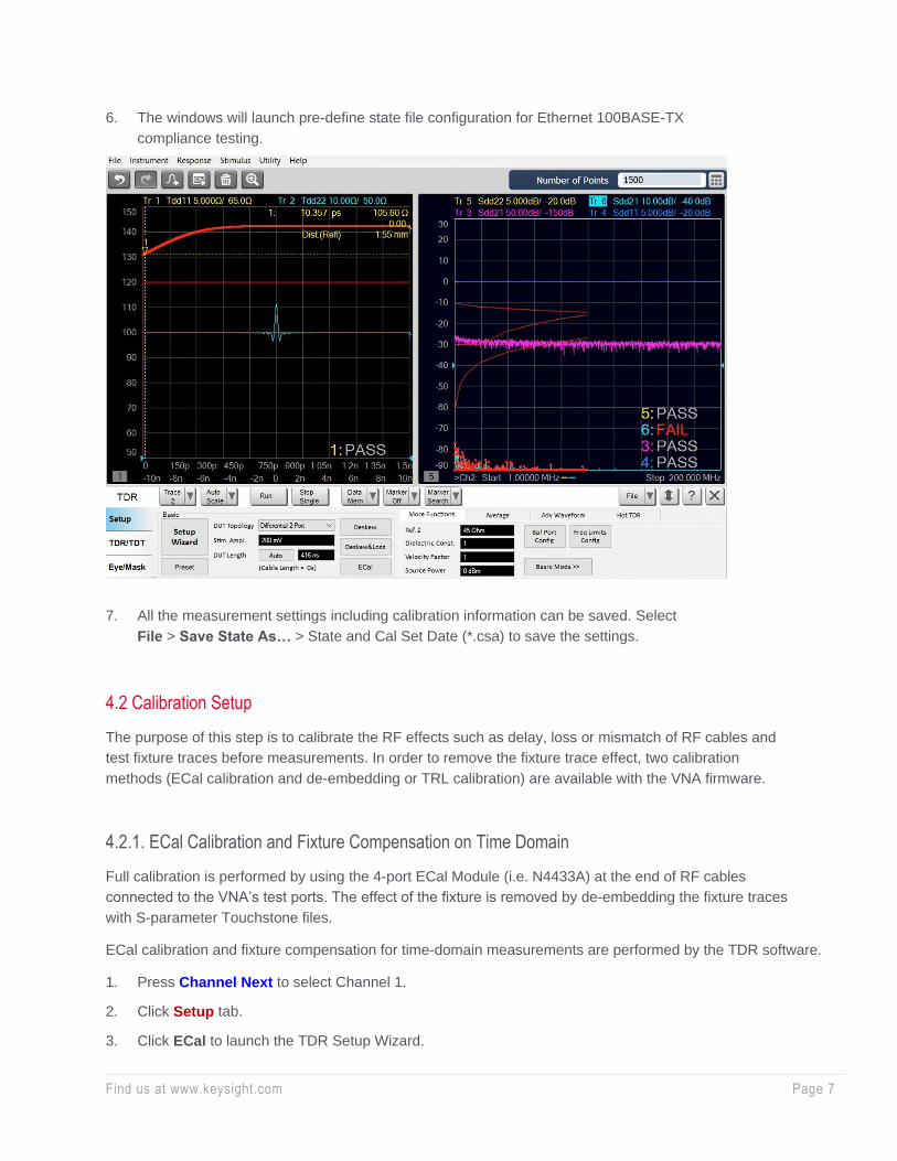
6. The windows will launch pre-define state file configuration for Ethernet 100BASE-TX
compliance testing.
7. All the measurement settings including calibration information can be saved. Select
File > Save State As… > State and Cal Set Date (*.csa) to save the settings.
4.2 Calibration Setup
The purpose of this step is to calibrate the RF effects such as delay, loss or mismatch of RF cables and
test fixture traces before measurements. In order to remove the fixture trace effect, two calibration
methods (ECal calibration and de-embedding or TRL calibration) are available with the VNA firmware.
4.2.1. ECal Calibration and Fixture Compensation on Time Domain
Full calibration is performed by using the 4-port ECal Module (i.e. N4433A) at the end of RF cables
connected to the VNA’s test ports. The effect of the fixture is removed by de-embedding the fixture traces
with S-parameter Touchstone files.
ECal calibration and fixture compensation for time-domain measurements are performed by the TDR software.
1. Press Channel Next to select Channel 1.
2. Click Setup tab.
3. Click ECal to launch the TDR Setup Wizard.

Find us at www.keysight.com Page 8
4. Connect the VNA ports (port 1 to 4) to the ECal module with RF cables.
5. Click Calibrate to perform ECal Calibration.
6. Click Next > to proceed.
7. Click Finish to complete the ECal.
8. Disconnect the ECal Module and connect the RF cables to the test fixtures. Click Fixture Comp to perform
fixture compensation. Once green check mark appears, click Finish to complete the compensation.
9. Connect DUT to the test fixture.
10. Open Setup tab.
Find us at www.keysight.com Page 9
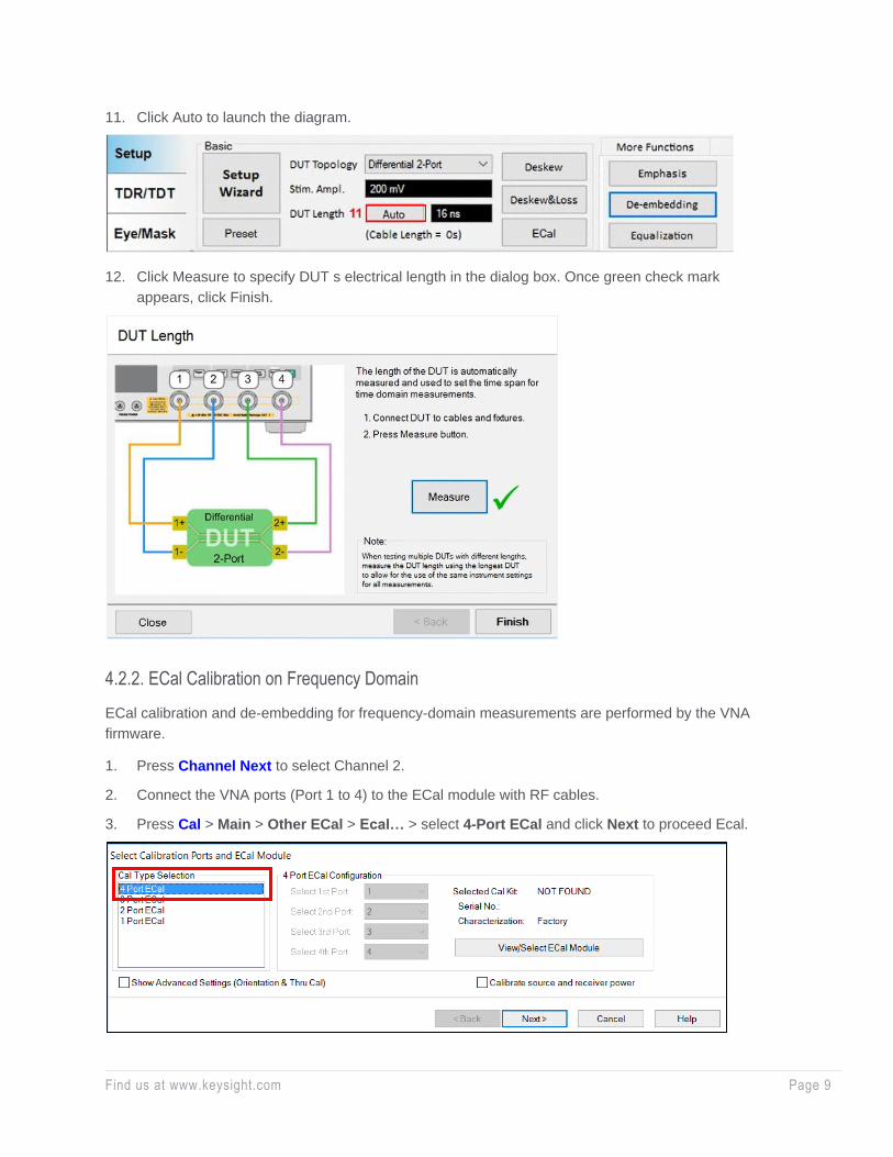
11. Click Auto to launch the diagram.
12. Click Measure to specify DUT s electrical length in the dialog box. Once green check mark
appears, click Finish.
4.2.2. ECal Calibration on Frequency Domain
ECal calibration and de-embedding for frequency-domain measurements are performed by the VNA
firmware.
1. Press Channel Next to select Channel 2.
2. Connect the VNA ports (Port 1 to 4) to the ECal module with RF cables.
3. Press Cal > Main > Other ECal > Ecal… > select 4-Port ECal and click Next to proceed Ecal.
Find us at www.keysight.com Page 10
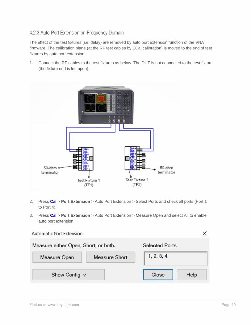
4.2.3 Auto-Port Extension on Frequency Domain
The effect of the test fixtures (i.e. delay) are removed by auto port extension function of the VNA
firmware. The calibration plane (at the RF test cables by ECal calibration) is moved to the end of test
fixtures by auto port extension.
1. Connect the RF cables to the test fixtures as below. The DUT is not connected to the test fixture
(the fixture end is left open).
2. Press Cal > Port Extension > Auto Port Extension > Select Ports and check all ports (Port 1
to Port 4).
3. Press Cal > Port Extension > Auto Port Extension > Measure Open and select All to enable
auto port extension.
Find us at www.keysight.com Page 11
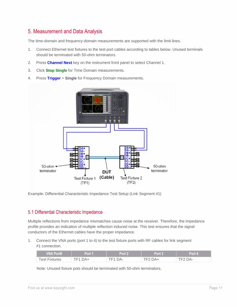
5. Measurement and Data Analysis
The time-domain and frequency-domain measurements are supported with the limit lines.
1. Connect Ethernet test fixtures to the test port cables according to tables below. Unused terminals
should be terminated with 50-ohm terminators.
2. Press Channel Next key on the instrument front panel to select Channel 1.
3. Click Stop Single for Time Domain measurements.
4. Press Trigger > Single for Frequency Domain measurements.
Example: Differential Characteristic Impedance Test Setup (Link Segment #1)
5.1 Differential Characteristic Impedance
Multiple reflections from impedance mismatches cause noise at the receiver. Therefore, the impedance
profile provides an indication of multiple reflection induced noise. This test ensures that the signal
conductors of the Ethernet cables have the proper impedance.
1. Connect the VNA ports (port 1 to 4) to the test fixture ports with RF cables for link segment
#1 connection.
VNA Port# Port 1 Port 2 Port 3 Port 4
Test Fixtures TF1 DA+ TF1 DA- TF2 DA+ TF2 DA-
Note: Unused fixture pots should be terminated with 50-ohm terminators.

Find us at www.keysight.com Page 12
2. Select Trace 1 (Tdd11).
3. Double-click the Trace to maximize the selected trace on the screen.
4. Click Stop Single.
5. Confirm the measured impedance is within the limit shown below. Otherwise, it will show Fail.
6. Select Trace 2 (Tdd22) and repeat Step 5-6 for the far end of the DUT.
Test Type Max Limit
Nominal differential characteristic impedance 100 Ω
7. Connect the VNA ports (port 1 to 4) to the test fixture ports with RF cables to measure differential
characteristic impedance of the link segment #2.
VNA Port# Port 1 Port 2 Port 3 Port 4
Test Fixtures TF1 DB+ TF1 DC- TF2 DB+ TF2 DC-
8. Repeat the same operation of Step 2 to 6 to measure Tdd11 and Tdd22 on link segment #2.
5.2 Differential Insertion Loss
1. Connect the VNA ports (port 1 to 4) to the test fixture ports with RF cables for link segment #1
connection.
VNA Port# Port 1 Port 2 Port 3 Port 4
Test Fixtures TF1 DA+ TF1 DA- TF2 DA+ TF2 DA-
Note: Unused fixture pots should be terminated with 50-ohm terminators.
2. Press Channel Next to select Channel 2.
3. Select Trace 3 (Sdd21).
4. Press Trigger > Single
5. Run and confirm the measured value is lower than the limit shown below. Otherwise, it will show Fail.
Start Frequency End Frequency Start Limit End Limit
1 MHz 10 MHz -2.5 dB -7.14 dB
10 MHz 20 MHz -7.14 dB -10.26 dB
20 MHz 40 MHz -10.26 dB -14.79 dB
40 MHz 60 MHz -14.79 dB -18.32 dB
60 MHz 80 MHz -18.32 dB -21.33 dB
80 MHz 100 MHz -21.33 dB -24.00 dB

Find us at www.keysight.com Page 13
6. Connect the VNA ports (port 1 to 4) to the test fixture ports with RF cables. Repeat the same operation
of step 3 to step 5 to confirm the measured values are within the specification for Link segment #2.
VNA Port# Port 1 Port 2 Port 3 Port 4
Test Fixtures TF1 DB+ TF1 DC- TF2 DB+ TF2 DC-
5.3 Differential Return Loss
1. Connect the VNA ports (port 1 to 4) to the test fixture ports with RF cables for link segment
#1 connection.
VNA Port# Port 1 Port 2 Port 3 Port 4
Test Fixtures TF1 DA+ TF1 DA- TF2 DA+ TF2 DA-
Note: Unused fixture pots should be terminated with 50-ohm terminators.
2. Press Channel Next to select Channel 2.
3. Select Trace 4 (Sdd11).
4. Press Trigger > Single.
5. Run and confirm the measured value shall meet or exceed the limit shown below. Otherwise, it will
show Fail.
Start Frequency End Frequency Start Limit End Limit
1 MHz 20 MHz -15 dB -15 dB
20 MHz 40 MHz -15 dB -11.99 dB
40 MHz 60 MHz -11.99 dB -10.23 dB
60 MHz 80 MHz -10.23 dB -8.98 dB
80 MHz 100 MHz -8.98 dB -8.01 dB
6. Select Trace 5 (Sdd22).
7. Press Trigger > Single.
8. Run and confirm the measured value shall meet or exceed the limit.
9. Connect the VNA ports (port 1 to 4) to the test fixture ports with RF cables. Repeat the same
operation of step 3 to step 8 to confirm the measured values are within the specification for
link segment #2.
VNA Port# Port 1 Port 2 Port 3 Port 4
Test Fixtures TF1 DB+ TF1 DC- TF2 DB+ TF2 DC-
Find us at www.keysight.com Page 14
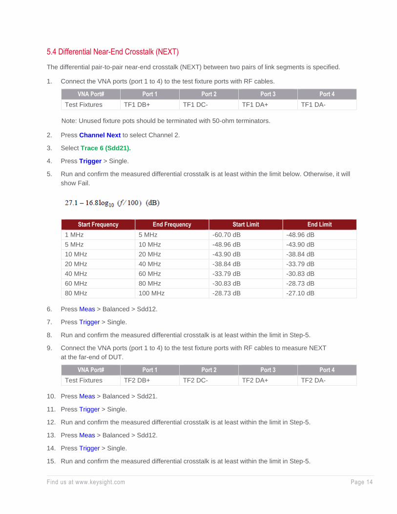
5.4 Differential Near-End Crosstalk (NEXT)
The differential pair-to-pair near-end crosstalk (NEXT) between two pairs of link segments is specified.
1. Connect the VNA ports (port 1 to 4) to the test fixture ports with RF cables.
VNA Port# Port 1 Port 2 Port 3 Port 4
Test Fixtures TF1 DB+ TF1 DC- TF1 DA+ TF1 DA-
Note: Unused fixture pots should be terminated with 50-ohm terminators.
2. Press Channel Next to select Channel 2.
3. Select Trace 6 (Sdd21).
4. Press Trigger > Single.
5. Run and confirm the measured differential crosstalk is at least within the limit below. Otherwise, it will
show Fail.
Start Frequency End Frequency Start Limit End Limit
1 MHz 5 MHz -60.70 dB -48.96 dB
5 MHz 10 MHz -48.96 dB -43.90 dB
10 MHz 20 MHz -43.90 dB -38.84 dB
20 MHz 40 MHz -38.84 dB -33.79 dB
40 MHz 60 MHz -33.79 dB -30.83 dB
60 MHz 80 MHz -30.83 dB -28.73 dB
80 MHz 100 MHz -28.73 dB -27.10 dB
6. Press Meas > Balanced > Sdd12.
7. Press Trigger > Single.
8. Run and confirm the measured differential crosstalk is at least within the limit in Step-5.
9. Connect the VNA ports (port 1 to 4) to the test fixture ports with RF cables to measure NEXT
at the far-end of DUT.
VNA Port# Port 1 Port 2 Port 3 Port 4
Test Fixtures TF2 DB+ TF2 DC- TF2 DA+ TF2 DA-
10. Press Meas > Balanced > Sdd21.
11. Press Trigger > Single.
12. Run and confirm the measured differential crosstalk is at least within the limit in Step-5.
13. Press Meas > Balanced > Sdd12.
14. Press Trigger > Single.
15. Run and confirm the measured differential crosstalk is at least within the limit in Step-5.
Find us at www.keysight.com Page 15
6. Manual Setup
The procedures of manual setup for time domain and frequency domain measurements are introduced in
this section for reference. All the required testing parameters have been properly set and saved in the
respective standards testing state file (*.tdr).
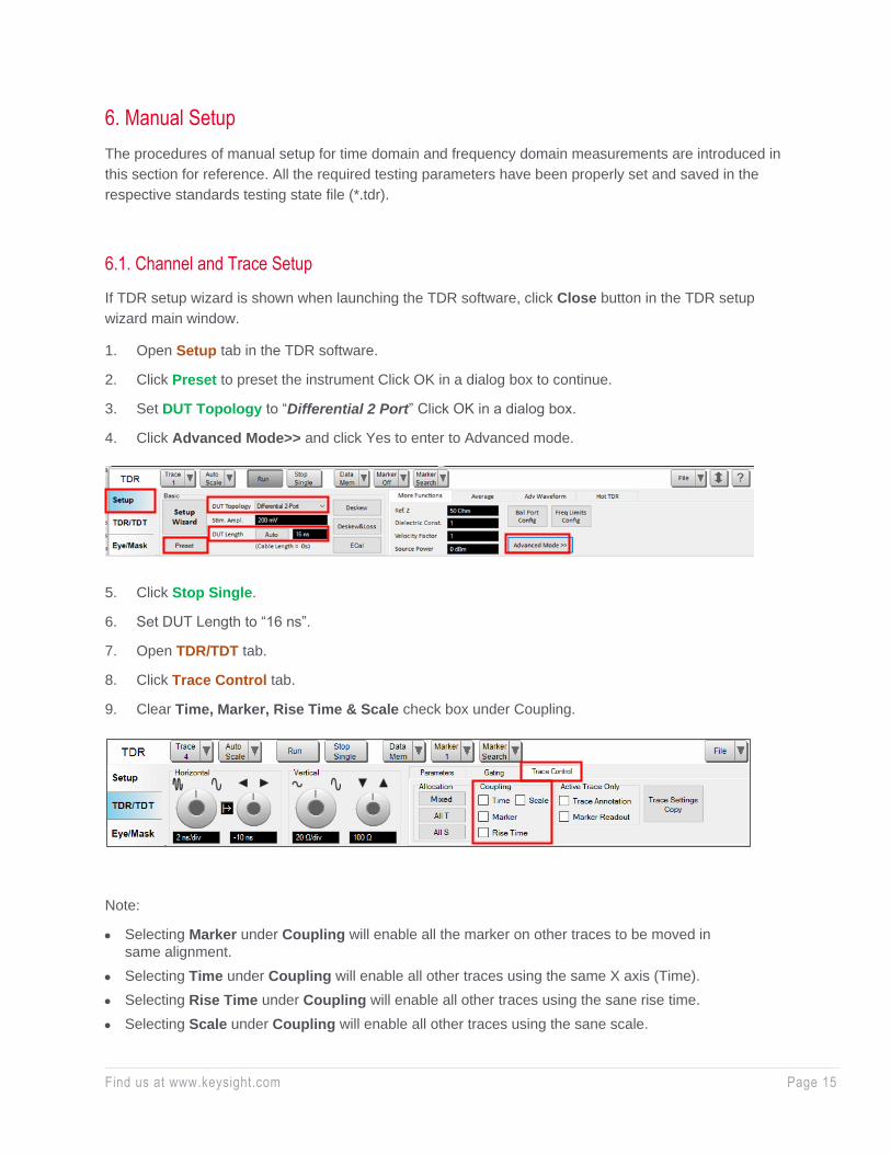
6.1. Channel and Trace Setup
If TDR setup wizard is shown when launching the TDR software, click Close button in the TDR setup
wizard main window.
1. Open Setup tab in the TDR software.
2. Click Preset to preset the instrument Click OK in a dialog box to continue.
3. Set DUT Topology to “Differential 2 Port” Click OK in a dialog box.
4. Click Advanced Mode>> and click Yes to enter to Advanced mode.
5. Click Stop Single.
6. Set DUT Length to “16 ns”.
7. Open TDR/TDT tab.
8. Click Trace Control tab.
9. Clear Time, Marker, Rise Time & Scale check box under Coupling.
Note:
• Selecting Marker under Coupling will enable all the marker on other traces to be moved in
same alignment.
• Selecting Time under Coupling will enable all other traces using the same X axis (Time).
• Selecting Rise Time under Coupling will enable all other traces using the sane rise time.
• Selecting Scale under Coupling will enable all other traces using the sane scale.
Find us at www.keysight.com Page 16
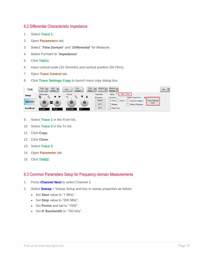
6.2 Differential Characteristic Impedance
1. Select Trace 1.
2. Open Parameters tab.
3. Select “Time Domain” and “Differential” for Measure.
4. Select Formant to “Impedance”.
5. Click Tdd11.
6. Input vertical scale (10 Ohm/div) and vertical position (50 Ohm).
7. Open Trace Control tab.
8. Click Trace Settings Copy to launch trace copy dialog box.
9. Select Trace 1 in the From list.
10. Select Trace 2 in the To list.
11. Click Copy.
12. Click Close.
13. Select Trace 2.
14. Open Parameter tab.
15. Click Tdd22.
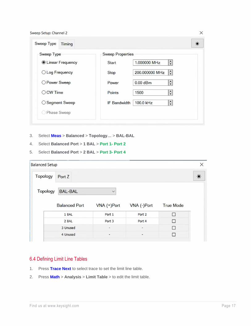
6.3 Common Parameters Setup for Frequency-domain Measurements
1. Press Channel Next to select Channel 2.
2. Select Sweep > Sweep Setup and key-in sweep properties as below:
• Set Start value to “1 MHz”.
• Set Stop value to “200 MHz”.
• Set Points and set to “1500”.
• Set IF Bandwidth to “100 kHz”.
Find us at www.keysight.com Page 17
3. Select Meas > Balanced > Topology… > BAL-BAL
4. Select Balanced Port > 1 BAL > Port 1- Port 2
5. Select Balanced Port > 2 BAL > Port 3- Port 4
6.4 Defining Limit Line Tables
1. Press Trace Next to select trace to set the limit line table.
2. Press Math > Analysis > Limit Table > to edit the limit table.
Find us at www.keysight.com Page 18 This information is subject to change without notice. © Keysight Technologies, 2020, Published in USA, December 14, 2020, 3120-1567.EN
Learn more at: www.keysight.com
For more information on Keysight Technologies’ products, applications or services,
please contact your local Keysight office. The complete list is available at:
www.keysight.com/find/contactus
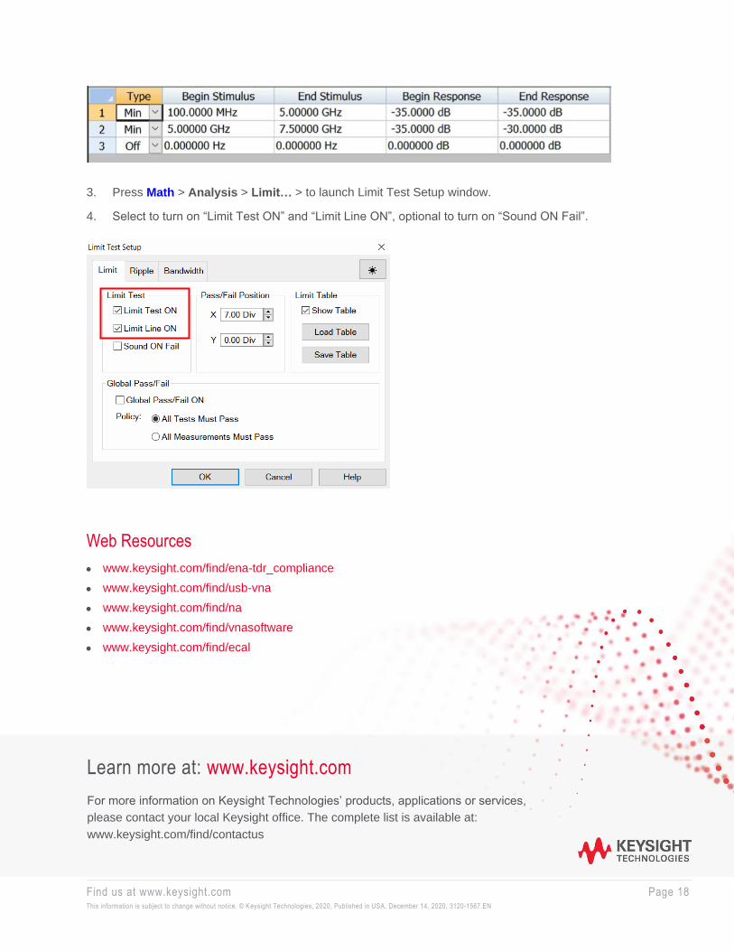
3. Press Math > Analysis > Limit… > to launch Limit Test Setup window.
4. Select to turn on “Limit Test ON” and “Limit Line ON”, optional to turn on “Sound ON Fail”.
Web Resources
• www.keysight.com/find/ena-tdr_compliance
• www.keysight.com/find/usb-vna
• www.keysight.com/find/na
• www.keysight.com/find/vnasoftware
• www.keysight.com/find/ecal