e6 install manual - encore automotive...
TRANSCRIPT
E6 IN REV. A 1
E6
PROFESSIONAL REMOTE CAR STARTER & 4 CHANNEL ALARM SYSTEM
INSTALLATION MANUAL
This unit is designed for professional installation only and must be installed by an Encore authorized dealer. Please register this product at
www.encoreautomotivesystems.com.
E6 IN REV. A 2
Precautions: Please read carefully This Remote Starter with Alarm and Keyless Entry System has been designed to be installed BY PROFESSIONAL INSTALLERS on fuel-injected vehicles with an automatic transmission ONLY. � Never install this remote starter on a manual transmission vehicle. � This system must be installed and wired through a safety switch so it will not start in any forward or
reverse gear. � Once you install this system, you must verify that the vehicle will not start in any forward or reverse
gear, regardless of the type of vehicle. � Read the operation manual for operating. � Do not install any component near the brake, gas pedal or steering linkage. � Some vehicles have a factory installed transponder immobilizer system that can severely complicate
the installation. There is a possibility that this system cannot be installed on some immobilizer-equipped vehicles.
� Most vehicles have an SRS air bag system. Use extreme care and do not probe any wires of the SRS system.
� Disconnect the car battery before beginning work on the vehicle. � Check behind panels before drilling any holes. Ensure that no wiring harness or other components
are located behind the panels that would otherwise be damaged. � Do not use conventional crimp lock, bullet on any wiring. Poor wiring, i.e. taped joints will possibly
introduce unreliability into the alarm system and may result in false alarms or incorrect operation. We suggest soldering all connection points.
� Install the wiring neatly under carpets or behind trim to prevent possible damage to wires. FOR AUTHORIZED DEALER TECHNICAL SUPPORT, PLEASE CALL Toll Free: (855) GO-ENCORE : 8:00 am TO 5:00 pm PST. WARNINGS: As with any product that performs automatic functions, there are certain safety precautions that you must practice and be aware of. 1. Keep the transmitter out of children’s reach. 2. Do not leave anyone in the vehicle while running on remote control. 3. Alert servicing personnel that the vehicle can be started automatically. 4. Do not start the vehicle by remote while it’s in an enclosed area or garage. 5. Always apply the parking brake and lock the vehicle as you exit the vehicle. 6. The vehicle windows must be rolled up. 7. Should the unit malfunction, disconnect the fuse until the problem is corrected. 8. The use and operations of this system is the sole responsibility of the operator. 9. Some areas may have local ordinances that prohibit leaving a vehicle running on public streets. 10.It is not safe to remote start the vehicle if the vehicle is parked on a steep incline. Do not start the vehicle by remote while it’s in an enclosed area or garage.
E6 IN REV. A 3
INSTALLATION DIAGRAM
E6 IN REV. A 4
20A
20ARed: Remote Start Power 1
Red: Remote Start Power 2
Violet: Starter (+) Output
Pink: Ignition 2 (+) Output
Yellow: Ignition 1 (+) Output
Brown: Acc/Heater (+) Output
6 PIN HEAVY GAUGE WIRE HARNESS
5 PIN WIRE HARNESS
Red: 12v + Battery Power Brown: Siren (+) Output
Black: System Main Ground (-)
White: Parking Light Relay Output
Red/White: Parking Light Relay Power Input
3 PIN, DOOR LOCK CONNECTOR
1. Blue Wire
3. Green Wire ( - ) Lock Pulse ( + ) Unlock Pulse
( - ) Unlock Pulse (+) Lock Pulse
WIRING Keep wiring away from moving engine parts, exhaust pipes and high-tension cable. Be sure to tape wires that pass through holes on the firewall to prevent fraying.
CAUTION: Do not connect the wire harness to the control module until all wiring to vehicle is complete.
E6 IN REV. A 5
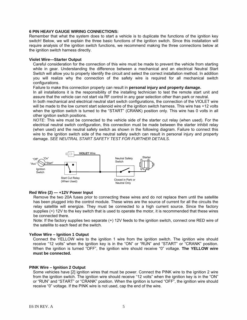
6 PIN HEAVY GAUGE WIRING CONNECTIONS: Remember that what the system does to start a vehicle is to duplicate the functions of the ignition key switch! Below, we will explain the three basic functions of the ignition switch. Since this installation will require analysis of the ignition switch functions, we recommend making the three connections below at the ignition switch harness directly. Violet Wire—Starter Output
Careful consideration for the connection of this wire must be made to prevent the vehicle from starting while in gear. Understanding the difference between a mechanical and an electrical Neutral Start Switch will allow you to properly identify the circuit and select the correct installation method. In addition you will realize why the connection of the safety wire is required for all mechanical switch configurations. Failure to make this connection properly can result in personal injury and property damage. In all installations it is the responsibility of the installing technician to test the remote start unit and assure that the vehicle can not start via RF control in any gear selection other than park or neutral. In both mechanical and electrical neutral start switch configurations, the connection of the VIOLET wire will be made to the low current start solenoid wire of the ignition switch harness. This wire has +12 volts when the ignition switch is turned to the “START” (CRANK) position only. This wire has 0 volts in all other ignition switch positions. NOTE: This wire must be connected to the vehicle side of the starter cut relay (when used). For the electrical neutral switch configuration, this connection must be made between the starter inhibit relay (when used) and the neutral safety switch as shown in the following diagram. Failure to connect this wire to the ignition switch side of the neutral safety switch can result in personal injury and property damage. SEE NEUTRAL START SAFETY TEST FOR FURTHER DETAILS.
Start Cut Relay(When Used)
VIOLET Wire
Closed in Park or Neutral Only
IgnitionSwitch
“Start”“On” Neutral Safety
Switch“Acc”
“Off”Starter
Red Wire (2) — +12V Power Input
Remove the two 20A fuses prior to connecting these wires and do not replace them until the satellite has been plugged into the control module. These wires are the source of current for all the circuits the relay satellite will energize. They must be connected to a high current source. Since the factory supplies (+) 12V to the key switch that is used to operate the motor, it is recommended that these wires be connected there. Note: If the factory supplies two separate (+) 12V feeds to the ignition switch, connect one RED wire of the satellite to each feed at the switch.
Yellow Wire – Ignition 1 Output Connect the YELLOW wire to the ignition 1 wire from the ignition switch. The ignition wire should receive “12 volts” when the ignition key is in the “ON” or “RUN” and “START” or “CRANK” position. When the ignition is turned “OFF”, the ignition wire should receive “0” voltage. The YELLOW wire must be connected.
PINK Wire – Ignition 2 Output
Some vehicles have [2] ignition wires that must be power. Connect the PINK wire to the ignition 2 wire from the ignition switch. The ignition wire should receive “12 volts” when the ignition key is in the “ON” or “RUN” and “START” or “CRANK” position. When the ignition is turned “OFF”, the ignition wire should receive “0” voltage. If the PINK wire is not used, cap the end of the wire.
E6 IN REV. A 6
Brown Wire –Accessory Output (Heater /AC Output)
Connect the BROWN wire to the accessory wire in the vehicle that powers the climate control system. An accessory wire will show + 12 volts when the ignition switch is turned to the “ACCESSORY” or “ON” and “RUN” positions, and will show 0 Volts when the key is turned to the “OFF” and “START” or “CRANK” position. There will often be more than one accessory wire in the ignition harness. The correct accessory wire will provide power to the vehicle’s climate control system. Some vehicles may have separate wires for the blower motor and the air conditioning compressor. In such cases, it will be necessary to add a relay to power the second accessory wire.
RS232 Two way SERIAL DATA PORT CONNECTION: This connector is to be used for Serial Data communications with idatalink modules by Encore only! DO NOT CONNECT THIS TO ANY OTHER WIRING! This port will only operate correctly with Encore idatalink Modules.
2 PIN WHITE CONNECTOR (THE LED STATUS INDICATOR): The led indicator status should be mounted in a highly visible area such as top of the dashboard, on top of the shifter console or on the dashboard face. Leave at least 6mm space behind the mounting location for LED housing. Once a suitable location is chosen, drill a 6mm hole. Run the LED wires through the hole then press the 2 pin LED housing into place. Route the LED wires to the control module.
5 PIN WIRE HARNESS: RED / WHITE WIRE –PARKING LIGHT RELAY INPUT —
The RED/WHITE wire is the input to the flashing parking light relay. The connection of the RED/WHITE wire will determine the output polarity of the flashing parking light relay. If the vehicle you are working on has +12volt switched parking lights, you don’t need connect this wire. This wire is already connected to +12volt. If the vehicle’s parking lights are ground switched, cut the RED/WHITE wire, connect the RED/WHITE wire to chassis ground.
WHITE WIRE — PARKING LIGHT RELAY OUTPUT (+12 V 10A OUTPUT) —
Connect the WHITE wire to the parking light wire coming from the headlight switch. Do not connect the WHITE wire to the dashboard lighting dimmer switch. (Damage to the dimmer will result). The limitation of the WHITE wire is 10 AMP max. Do not exceed this limit or damage to the alarm and parking relay will result.
BLACK WIRE — SYSTEM GROUND – This is the main ground connection of the alarm module. Make this connection to a solid section of the vehicle frame. Do not connect this wire to any existing ground wires supplied by the factory wire loom, make the connection to the vehicle’s frame directly.
BROWN WIRE – (+) SIREN OUTPUT – This wire is provides power to the supplied siren. Connect the Brown wire to the Red wire of the siren. Connect the Black wire of the siren to a stable chassis ground.
RED WIRE — SYSTEM POWER (+12V CONSTANT) — The RED wire supplies power to the system. Connect this wire to a stable constant +12 volt source.
E6 IN REV. A 7
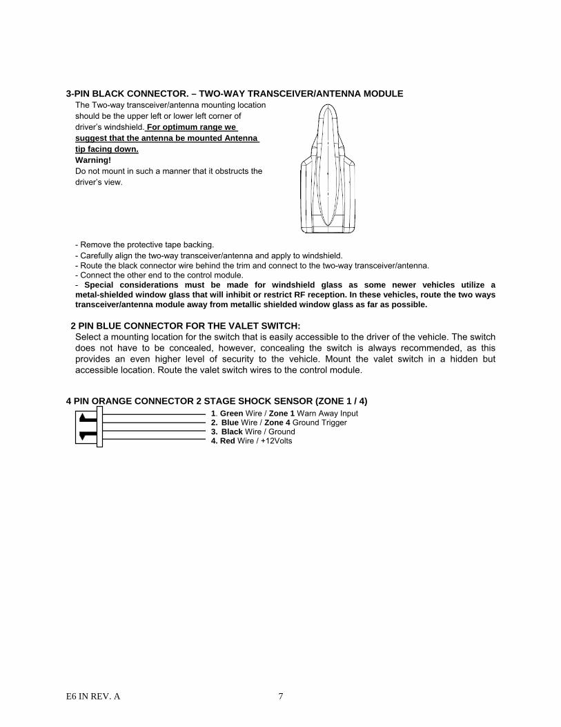
3-PIN BLACK CONNECTOR. – TWO-WAY TRANSCEIVER/ANTENNA MODULE
The Two-way transceiver/antenna mounting location should be the upper left or lower left corner of driver’s windshield. For optimum range we suggest that the antenna be mounted Antenna tip facing down. Warning! Do not mount in such a manner that it obstructs the driver’s view.
- Remove the protective tape backing. - Carefully align the two-way transceiver/antenna and apply to windshield. - Route the black connector wire behind the trim and connect to the two-way transceiver/antenna. - Connect the other end to the control module. - Special considerations must be made for windshield glass as some newer vehicles utilize a metal-shielded window glass that will inhibit or restrict RF reception. In these vehicles, route the two ways transceiver/antenna module away from metallic shielded window glass as far as possible.
2 PIN BLUE CONNECTOR FOR THE VALET SWITCH: Select a mounting location for the switch that is easily accessible to the driver of the vehicle. The switch does not have to be concealed, however, concealing the switch is always recommended, as this provides an even higher level of security to the vehicle. Mount the valet switch in a hidden but accessible location. Route the valet switch wires to the control module.
4 PIN ORANGE CONNECTOR 2 STAGE SHOCK SENSOR (ZONE 1 / 4) 1. Green Wire / Zone 1 Warn Away Input
2. Blue Wire / Zone 4 Ground Trigger 3. Black Wire / Ground 4. Red Wire / +12Volts
E6 IN REV. A 8
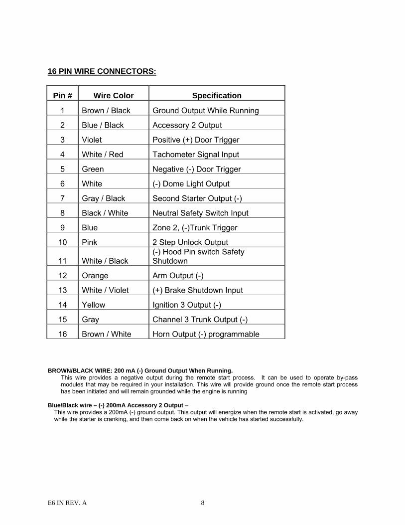
16 PIN WIRE CONNECTORS:
Pin # Wire Color Specification
1 Brown / Black Ground Output While Running
2 Blue / Black Accessory 2 Output
3 Violet Positive (+) Door Trigger
4 White / Red Tachometer Signal Input
5 Green Negative (-) Door Trigger
6 White (-) Dome Light Output
7 Gray / Black Second Starter Output (-)
8 Black / White Neutral Safety Switch Input
9 Blue Zone 2, (-)Trunk Trigger
10 Pink 2 Step Unlock Output
11 White / Black (-) Hood Pin switch Safety Shutdown
12 Orange Arm Output (-)
13 White / Violet (+) Brake Shutdown Input
14 Yellow Ignition 3 Output (-)
15 Gray Channel 3 Trunk Output (-)
16 Brown / White Horn Output (-) programmable BROWN/BLACK WIRE: 200 mA (-) Ground Output When Running.
This wire provides a negative output during the remote start process. It can be used to operate by-pass modules that may be required in your installation. This wire will provide ground once the remote start process has been initiated and will remain grounded while the engine is running
Blue/Black wire – (-) 200mA Accessory 2 Output –
This wire provides a 200mA (-) ground output. This output will energize when the remote start is activated, go away while the starter is cranking, and then come back on when the vehicle has started successfully.

E6 IN REV. A 9
87
87a
85
30
86
IN4003 Diode
H2/1 Blue / Black wire from control module
“Start”
“On” XCut
“Acc”“Off”
H1/4 Yellow wire (Ignition 1 output)form Heavy Gauge wire harness
To Ignition Coil
Violet wire – Positive Door Switch Sensing Input (Zone 3)–
This wire is the positive trigger input wire for positive door pin switch. This wire is connection for "positive" type factory door pins(typical FORD MOTOR). Locate the "common wire" for all door pins and make the connection of the VIOLET Wire here.
White / Red wire – Tachometer Signal Connection –
Note: You should connect this wire if you program the Start Feature E – 2 to “Tachometer checking type”, otherwise do not connect this wire and tap the end. Note: No connection of this wire is required, if you use the voltage or timer checking type mode. This input provides the remote start system with information about the engine’s revolutions per minute (RPM). It can be connected to the negative side of the coil in vehicle with conventional coils. In multi-coil and high energy ignition system locating a proper signal may be more difficult. Once connected, To test for a tachometer wire, a multi-meter capable of test AC voltage must be used. The tachometer wire will show between 1V and 6V AC at idle, and will increase as engine RPM increases. In multi-coil ignition system, the system can learn individual coil wire. Individual coil wires in a multi-coil ignition system will register lower amounts of AC voltage. Also, if necessary, the system can use a fuel injector control wire for engine speed sensing. Common locations for a tachometer wire are the ignition coil itself, the back of the gauges, engine computers, and automatic transmission computers. IMPORTANT! Do not test tachometer wires with a test light or logic probe. The vehicle will be damaged. How to find a tachometer wire with your multi-meter 1. Set the ACV or AC voltage (12V or 20V is fine.) 2. Attach the (-) probe of the meter to chassis ground. 3. Start and run the vehicle. 4. Probe the wire you suspect of being the tachometer wire with the red probe of the meter. 5. If this is the correct wire the meter will read between 1V and 6V.
IMPORTANT NOTE: No initial programming necessary. Default = voltage sensing mode Green wire – Negative Door Switch Sensing Input (Zone 3) –
This wire is the ground trigger input wire for negative door pin switch. This wire is connection for "grounding" type factory door pins locate the "common wire" that connects the door pin switches. Make the connection of the GREEN Wire here.
White wire – (-) 200mA Dome Light Control Output –
This wire becomes grounded when the dome light controls circuit active. The current capacity of this wire is 200mA. This wire can control the operation of the interior lights. An optional 10 Amps relay can be used to this system for interior lights operation.
87a86
87
3085
Fuse
White Wire +12V
Door Switch
CourtesyLight
a). Upon disarming, the interior lights will remain on for 30 seconds. b). If the alarm is triggered, the interior light will flash for the same duration as the siren. Gray / Black WIRE: 200 mA (-) Second Starter Output.
This line can be used if a second starter line is needed. Some vehicles require a two-starter line to remote start. This wire provides a negative output that will work the same way as the Violet starter line in connector H1.
Black/White wire – (-) Neutral Safety Switch Input or (-) Enable Switch Input –
E6 IN REV. A 10
When the BLACK/WHITE wire is grounded, the remote start unit is operable. When this wire is open from ground, the remote start is disabled.
1. The optional “remote start toggle switch” can be added on to temporarily disable the Remote Start Device, it can prevent the vehicle from being remote started accidentally. This feature is useful if the vehicle is being serviced or stored in an enclosed area. To disable the remote start, move the optional remote start enable toggle switch to the OFF position. To enable the remote start, move the optional remote start enable toggle switch to the ON position.
2. If needed, this wire can connect to the PARK/NEUTRAL switch in the vehicle. (See the TESTING YOUR INSTALLATION GUIDE) IMPORTANT NOTE: This wire must have a “GROUND” to operate remote start.
Blue wire – Ground Instant Trigger Input (Zone 2) –
This wire is the ground trigger input wire for hood and or trunk pin switches. Pink wire – (-) 200mA Programmable Output 2 Steps Unlock Output (Factory default setting) (See Alarm Feature
Programming) The 2 steps unlock feature will work for the most fully electronic door lock circuit. The vehicle must have an electronic door lock switch (not the lock knob or key switch), which locks and unlocks all of vehicle's doors. When wired for this feature, press the disarm (or unlock) button one time will disarm the alarm and unlock the driver's door only. If, press disarm (or unlock) button two times within 3 seconds, the alarm will disarm and all doors will unlock. Factory Security Disarm Signal Output – This wire is designed to disarm a factory installed security system. This wire sends a negative (-) 1 seconds pulse upon a remote start and remote door unlocking. Some factory systems must be disarmed to allow remote starting. In most cases, this wire may be connected directly to the factory alarm disarm wire. The correct wire will show negative ground when the key is used to unlock the doors or trunk. This wire is usually found in the kick panel area in the wiring harness coming into the car body from the door. Start Status (Shock Sensor By-Pass Control) Output– This wire is designed to by-pass shock sensor module. This wire will supply an output at all times the remote start is operating plus an additional 3 seconds after the remote start unit turn off. Key Sensor By-Pass Output – This output is for a Key Sense wire by-pass that some Chrysler and Toyota vehicles need to activate remote start. This wire comes on when remote start is activated and stays on for 20 seconds.
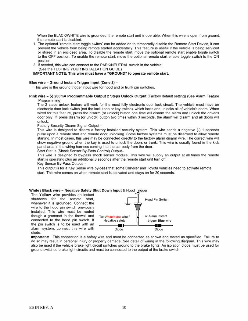
White / Black wire – Negative Safety Shut Down Input & Hood Trigger The Yellow wire provides an instant shutdown for the remote start, whenever it is grounded. Connect the wire to the hood pin switch previously installed. This wire must be routed though a grommet in the firewall and connected to the hood pin switch. If the pin switch is to be used with an alarm system, connect this wire with diode.
To: White/black wire / Negative safety
To: Alarm instant trigger Blue wire
Hood Pin Switch
Diode Diode
Important! This connection is a safety wire and must be connected as shown and tested as specifiled. Failure to do so may result in personal injury or property damage. See detail of wiring in the following diagram. This wire may also be used if the vehicle brake light circuit switches ground to the brake lights. An isolation diode must be used for ground switched brake light circuits and must be connected to the output of the brake switch.
E6 IN REV. A 11
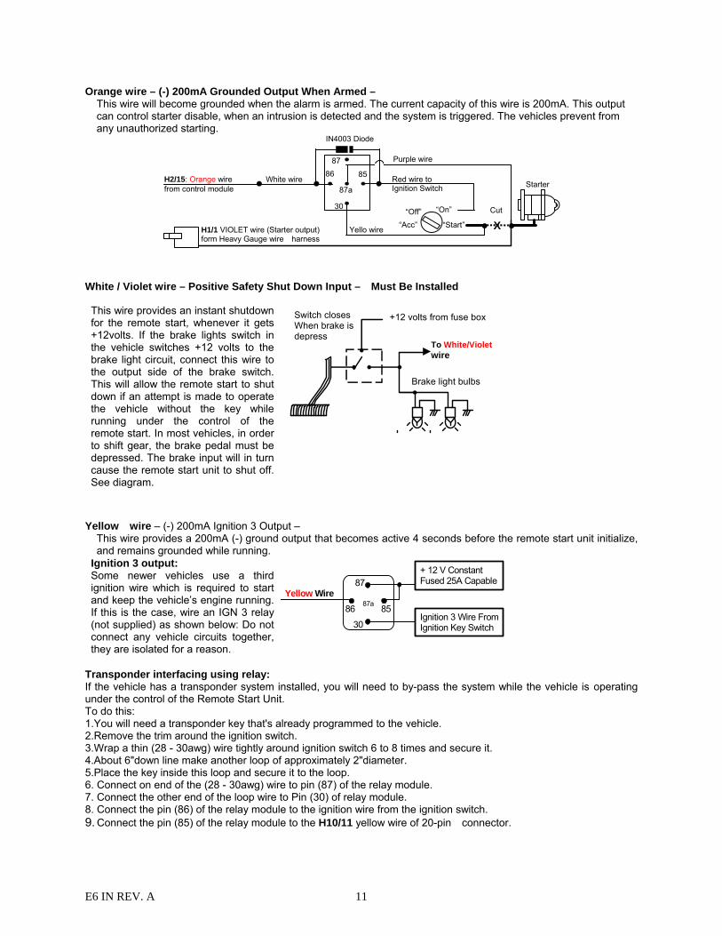
Orange wire – (-) 200mA Grounded Output When Armed – This wire will become grounded when the alarm is armed. The current capacity of this wire is 200mA. This output can control starter disable, when an intrusion is detected and the system is triggered. The vehicles prevent from any unauthorized starting.
87
87a
85
30
86
IN4003 Diode
H2/15: Orange wire from control module
“Start”
“On”
Purple wire
XCut
Yello wire
White wire
“Acc” “Off”
Starter
H1/1 VIOLET wire (Starter output) form Heavy Gauge wire harness
Red wire to Ignition Switch
White / Violet wire – Positive Safety Shut Down Input – Must Be Installed
Yellow wire – (-) 200mA Ignition 3 Output –
This wire provides a 200mA (-) ground output that becomes active 4 seconds before the remote start unit initialize, and remains grounded while running.
Ignition 3 output: Some newer vehicles use a third ignition wire which is required to start and keep the vehicle’s engine running. If this is the case, wire an IGN 3 relay (not supplied) as shown below: Do not connect any vehicle circuits together, they are isolated for a reason.
Yellow Wire87a
Ignition 3 Wire From Ignition Key Switch
+ 12 V Constant Fused 25A Capable
30
8586
87
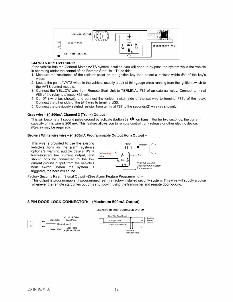
Transponder interfacing using relay: If the vehicle has a transponder system installed, you will need to by-pass the system while the vehicle is operating under the control of the Remote Start Unit. To do this: 1.You will need a transponder key that's already programmed to the vehicle. 2.Remove the trim around the ignition switch. 3.Wrap a thin (28 - 30awg) wire tightly around ignition switch 6 to 8 times and secure it. 4.About 6"down line make another loop of approximately 2"diameter. 5.Place the key inside this loop and secure it to the loop. 6. Connect on end of the (28 - 30awg) wire to pin (87) of the relay module. 7. Connect the other end of the loop wire to Pin (30) of relay module. 8. Connect the pin (86) of the relay module to the ignition wire from the ignition switch. 9. Connect the pin (85) of the relay module to the H10/11 yellow wire of 20-pin connector.
This wire provides an instant shutdown for the remote start, whenever it gets +12volts. If the brake lights switch in the vehicle switches +12 volts to the brake light circuit, connect this wire to the output side of the brake switch. This will allow the remote start to shut down if an attempt is made to operate the vehicle without the key while running under the control of the remote start. In most vehicles, in order to shift gear, the brake pedal must be depressed. The brake input will in turn cause the remote start unit to shut off. See diagram.
+12 volts from fuse box
To White/Violet wire
Brake light bulbs
Switch closes When brake is depress
E6 IN REV. A 12
GM VATS KEY OVERRIDE: If the vehicle has the General Motor VATS system installed, you will need to by-pass the system while the vehicle is operating under the control of the Remote Start Unit. To do this: 1. Measure the resistance of the resistor pellet on the ignition key then select a resistor within 5% of the key’s
value. 2. Locate the pair of VATS wires in the vehicle, usually a pair of thin gauge wires running from the ignition switch to
the VATS control module. 3. Connect the YELLOW wire from Remote Start Unit to TERMINAL #85 of an external relay. Connect terminal
#86 of the relay to a fused +12 volt. 4. Cut (#1) wire (as shown), and connect the ignition switch side of the cut wire to terminal #87a of the relay.
Connect the other side of the (#1) wire to terminal #30. 5. Connect the previously seleted resistor from terminal #87 to the second(#2) wire (as shown).
Gray wire – (-) 200mA Channel 3 (Trunk) Output –
This will become a 1 second pulse ground by activate (button 3) on transmitter for two seconds, the current capacity of this wire is 200 mA. This feature allows you to remote control trunk release or other electric device. (Realay may be required).
Brown / White wire wire – (-) 200mA Programmable Output Horn Output –
This wire is provided to use the existing vehicle's horn as the alarm system's optional's warning audible device. It's a transistorized low current output, and should only be connected to the low current ground output from the vehicle's horn switch. When the system is triggered, the horn will sound.
8586
87 87a
30
White/Blue wire
To horn
+ 12 V
+12V Or Ground Depending On System Requirements
FUSE
Factory Security Rearm Signal Output –(See Alarm Feature Programming) –
This output is programmable. If programmed rearm a factory installed security system. This wire will supply a pulse whenever the remote start times out or is shut dowm using the transmitter and remote door locking.
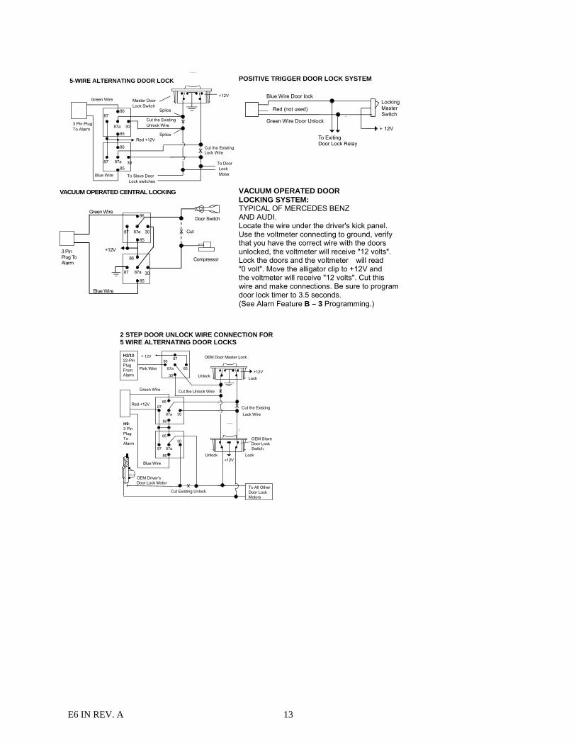
3 PIN DOOR LOCK CONNECTOR: (Maximum 500mA Output)
Blue Wire
Green Wire( - ) Lock Pulse( + ) Unlock Pulse
( - ) Unlock Pulse(+) Lock Pulse
Red(not used)
NEGATIVE TRIGGER DOOR LOCK SYSTEM
Red (not used)
Blue Wire Door Unlock
Green Wire Door Lock
LockingMaster Switch
To Exiting Door Lock Relay
E6 IN REV. A 13
VACUUM OPERATED CENTRAL LOCKING
Green Wire
Blue Wire
+12V
X Cut
Compressor
Door Switch
30
86
87a
85
87
30
86
87a
85
87
3 Pin Plug To Alarm
VACUUM OPERATED DOOR LOCKING SYSTEM: TYPICAL OF MERCEDES BENZ AND AUDI. Locate the wire under the driver's kick panel. Use the voltmeter connecting to ground, verify that you have the correct wire with the doors unlocked, the voltmeter will receive "12 volts". Lock the doors and the voltmeter will read "0 volt". Move the alligator clip to +12V and the voltmeter will receive "12 volts". Cut this wire and make connections. Be sure to program door lock timer to 3.5 seconds. (See Alarn Feature B – 3 Programming.)
+12V Master Door Lock Switch
X
X
Splice
Splice
Cut the Existing Lock Wire
To Door Lock Motor To Slave Door
Lock switches
Cut the Existing Unlock Wire 3 Pin Plug
To Alarm
5-WIRE ALTERNATING DOOR LOCK
30
86
87a
85
87
30
86
87a 85
87
Red +12V
Green Wire
Blue Wire
POSITIVE TRIGGER DOOR LOCK SYSTEM
Blue Wire Door lock
Green Wire Door Unlock
LockingMasterSwitch
To ExitingDoor Lock Relay
+ 12V
Red (not used)
2 STEP DOOR UNLOCK WIRE CONNECTION FOR 5 WIRE ALTERNATING DOOR LOCKS
+12V
Cut the ExistingLock Wire
Cut Existing Unlock X
Cut the Unlock Wire
LockUnlock
OEM Door Master Lock
OEM SlaveDoor LockSwitch
+12VLockUnlock
To All OtherDoor LockMotors
H2/13: 22-Pin Plug From Alarm
Pink Wire
x
X
Blue Wire
OEM Driver’s Door Lock Motor
+ 12V
85
86 87
87a
30
30
87 85
87a
86
30
87
85
87a
86
Green Wire
H9: 3 Pin Plug To Alarm
Red +12V

E6 IN REV. A 14
2 STEP DOOR UNLOCK WIRE CONNECTION FOR GROUND SWITCHED DOOR LOCKS
Cut Existing Unlock X
Lock Unlock
OEM Door Master Lock Switch
To All OtherDoor LockMotors
White/Green Wire
OEM Door Lock Motor
Existing Neg.Lock Wire
Existing Neg.Unlock Wire
86
30
85 87
87a
+ 12V
Green Wire Door Lock
Blue Wire Door Unlock OEM Door
Lock Relay
H2/13: 22-Pin Plug From Alarm
H9: 3 Pin Plug To Alarm
2 STEP DOOR UNLOCK WIRE CONNECTION FOR POSITIVE SWITCHED DOOR LOCKS
Cut Existing Unlock X
LockUnlock
OEM Door Master Lock Switch
To All OtherDoor LockMotors
White/Green Wire
OEM Driver'sDoor LockMotor
+ 12V Existing Pos.Lock Wire
Existing Pos.Unlock Wire30
87a
87
86 85
+12V
+ 12V
OEM Door Lock Relay
8630
85
8787a
Green WireDoor Unlock
Blue Wire Door Lock
H2/13: 22-Pin Plug From Alarm
H9: 3 Pin Plug To Alarm
PROGRAMMING PROGRAMMING TRANSMITTER: Note: This mode will only retain the last 4 remote transmitters programmed. If the transmitter memory is exceeded, the security system will start deleting transmitters from memory in chronological order. 1. Turn the Ignition 'switch ‘OFF/ON’ 4 TIMES and stay in ON position.
“Within 15 seconds”. 2. Push the Valet switch 4 times and hold it on the 4th push until a long chirp is heard then release the valet switch.
You are now in the Transmitter programming mode. 3. Press and hold any button of the transmitter until the siren responds with a confirming chirp, indicating the signal
has been stored into memory. 4. If you have additional transmitters (up to 4) that need to be programmed, repeat step 3 for each transmitter. Exit: Turn Ignition to 'OFF' position, or leave it for 15 seconds. 3 long chirps & 3 parking light flashes will confirm exit. FEATURES PROGRAMMING: ALARM FEATURE “A” PROGRAMMING: 1. Turn the Ignition 'switch ‘ON/OFF’ 3 TIMES and stay in OFF position. 2. Push the Valet switch 3 times (holding in on the 3rd push) until one long chirp is heard, then release the valet
switch. You are now in the Alarm feature “A” programming mode. 3. Press and release the transmitter button corresponding to the feature you want to program. a. The siren chirps and LED pause will indicate previously setting. b. The factory default settings is always [1] LED flash, [1] chirp.
4 Depress the transmitter button to change the feature. Simple keep re-depressing the transmitter button until the system advances to your desired setting. Press the transmitter button corresponding to the feature you want to program.
Press Transmitter
Button
One Chirp / LED one pulse
Factory Default Setting
Two Chirps / LED two pulses
Three Chirps / LED three pulses
Four Chirps / LED four pulses
1 Active arming
Passive arming without passive door locking
Passive arming with passive door
locking.
2 Automatic Rearm off
Automatic Rearm on
3 Instant Door Ajar error chirp
45 seconds delay Door Ajar error chirp.
E6 IN REV. A 15
4 All Confirmation chirps on
Siren Confirmation chirp on only
Horn Confirmation chirp on only
All Confirmation chirps off
5 + Panic with Ignition off
Panic with Ignition on & off
Panic with Ignition on & off.
Panic with No time limit.
Without Panic function.
6 + With Alarm Function
Without Alarm Function
7 + Without Car-jack mode
Active Car-jack
mode
Passive Car-jack mode
8 + With Dome light turns on & off
after ignition on & off (45 second
door by-pass)
With Dome light turns on after ignition off (45 second door by-pass)
Without this feature
9 + Lock/Arm & Unlock/Disarm Confirmation
Chirp
Lock/Arm Confirmation Only
Exit: Turn Ignition to 'ON' position, or leave it for 15 seconds. 3 long chirps & 3 parking light flashes will confirm exit. 45 seconds Delay Door Ajar Error Chirp: This feature controls the error chirp that is generated if the system is armed with the door trigger active. This is useful in a vehicle that has a long dome light delay after the door has been closed. If the system is armed before the dome light has turned off, the security system will generate the door trigger error chirp. Use this feature to disable the door open error chirp. With Dome light turns on after ignition off: Some vehicles turn on the dome light when ignition key is turned off. After remote start, with alarm on, a false alarm may occur when the run time elapses and the dome light comes on. To prevent this from happing, program Alarm Feature A-8 to “With Dome light turns on after ignition off (45 second door by-pass)”. ALARM FEATURE “B” PROGRAMMING: 1 Turn the Ignition switch ‘ON/OFF’ 3 TIMES and stay in OFF position. 2 Push the Valet switch 4 times (holding in on the 4th push) until one long chirp is heard then release the valet
switch. You are now in the Alarm feature “B” programming mode. 3 Press and release the transmitter button corresponding to the feature you want to program. Press Transmitter Button
One Chirp / LED one pulse Factory Default Setting
Two Chirps / LED two pulses
Three Chirps / LED three pulses
Four Chirps / LED four pulses
1 Pathway Illumination
Feature “off”
Parking light turns “on” for 30- second
upon an unlock signal
Parking light turns “on” for 30- second upon an unlock signal & 10-second upon
a lock signal.
2 Ignition controlled door locks & unlocks
Ignition controlled door
locks only
Ignition controlled door unlocks only
Without ignition controlled door locks & unlocks
3 0.8 second door lock & unlock
3.5 second door lock & Unlock
0.8 second Lock, 0.35 second Unlock
0.8 sec. dbl Lock, 0.8 sec. dbl Unlock
E6 IN REV. A 16
Five Chirps = 0.8 second Lock, double 0.8 second. Unlock
Six Chirps = Double 0.8 second Lock, 0.8 second Unlock
Seven Chirps = Door lock with “Comfort Feature”
Eight Chirps = DBI Two step unlock ( DBI ONLY )**
Nine chirps = DBI Unlock ALL doors ( DBI Only )**
**Select either of these options when using Encore Two Way Data Bus Interface Only.
4 Brown Wire = (+) Constant Siren
output
Brown Wire =5-second (+)
pulse Siren output
Brown Wire = (+) Pulsing Output (Relay required for [-] Horn)
5 + 3 Hours Timer Start 2 Hours Timer Start
6 +
The Vehicle withoutTurbo
(The system Can not be Arm with the
engine running)
The Vehicle with Turbo (The system Can be Arm with the engine running)
The shock sensor will be
by-passed upon engine running. (The engine will run by itself after
the ignition is turned off)
The shock sensor by-pass three minutes after
armed. (The engine will run by itself after
the ignition is turned off)
Press and
buttons at
the same time
to control
Engine run time
for one minute
and the shock
sensor will be
by-passed upon
engine running.
Five chirps = Press and buttons at the same time to control Engine run time for three minutes and the shock sensor will be by-pass upon engine running. Six chirps = Press and buttons at the same time to control Engine run time for five minutes and the shock sensor will be by-passed upon engine running.
7. + Horn chirp Duration
Standard
Horn chirp Duration
50 mS
Horn chirp Duration
30 mS
Horn chirp duration
10 mS
Exit: Turn Ignition to 'ON' position, or leave it for 15 seconds. 3 long chirps & 3 parking light flashes will confirm exit. Comfort Feature: Some Vehicles have a special “COMFORT feature”. When you lock the door with the key, you can keep turning the key in the door for about 5 to 7 seconds and the window will close directly. If your vehicle has the “COMFORT feature” and you wish for the door to be locked and the window to be closed automatically at the same time by remote control, you can set the alarm feature “B-3 “with comfort feature”. ALARM FEATURE “C” PRORAMMING: 1 Turn the Ignition 'switch ‘ON/OFF’ 3 TIMES and stay in OFF position. 2 Push the Valet switch 5times (holding in on the 5th push) until one long chirp is heard then release the valet
switch. You are now in the Alarm feature “C” programming mode.
E6 IN REV. A 17
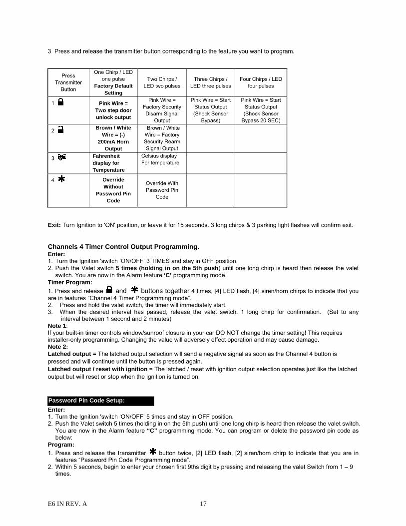
3 Press and release the transmitter button corresponding to the feature you want to program.
Press Transmitter
Button
One Chirp / LED one pulse
Factory Default Setting
Two Chirps / LED two pulses
Three Chirps / LED three pulses
Four Chirps / LED four pulses
1 Pink Wire = Two step door unlock output
Pink Wire = Factory Security Disarm Signal
Output
Pink Wire = Start Status Output (Shock Sensor
Bypass)
Pink Wire = Start Status Output (Shock Sensor
Bypass 20 SEC)
2 Brown / White Wire = (-)
200mA Horn Output
Brown / White Wire = Factory Security Rearm Signal Output
3 Fahrenheit display for Temperature
Celsius display For temperature
4 Override Without
Password Pin Code
Override With Password Pin
Code
Exit: Turn Ignition to 'ON' position, or leave it for 15 seconds. 3 long chirps & 3 parking light flashes will confirm exit. Channels 4 Timer Control Output Programming. Enter: 1. Turn the Ignition 'switch ‘ON/OFF’ 3 TIMES and stay in OFF position. 2. Push the Valet switch 5 times (holding in on the 5th push) until one long chirp is heard then release the valet
switch. You are now in the Alarm feature ‘C’ programming mode. Timer Program: 1. Press and release and buttons together 4 times, [4] LED flash, [4] siren/horn chirps to indicate that you are in features “Channel 4 Timer Programming mode”. 2. Press and hold the valet switch, the timer will immediately start. 3. When the desired interval has passed, release the valet switch. 1 long chirp for confirmation. (Set to any
interval between 1 second and 2 minutes) Note 1: If your built-in timer controls window/sunroof closure in your car DO NOT change the timer setting! This requires installer-only programming. Changing the value will adversely effect operation and may cause damage. Note 2: Latched output = The latched output selection will send a negative signal as soon as the Channel 4 button is pressed and will continue until the button is pressed again. Latched output / reset with ignition = The latched / reset with ignition output selection operates just like the latched output but will reset or stop when the ignition is turned on. Password Pin Code Setup: Enter: 1. Turn the Ignition 'switch ‘ON/OFF’ 5 times and stay in OFF position. 2. Push the Valet switch 5 times (holding in on the 5th push) until one long chirp is heard then release the valet switch.
You are now in the Alarm feature “C” programming mode. You can program or delete the password pin code as below:
Program: 1. Press and release the transmitter button twice, [2] LED flash, [2] siren/horn chirp to indicate that you are in
features “Password Pin Code Programming mode”. 2. Within 5 seconds, begin to enter your chosen first 9ths digit by pressing and releasing the valet Switch from 1 – 9
times.
E6 IN REV. A 18
3. Within 15 seconds of the last entered 9ths digit, turn the Ignition switch to “ON” position. 4. Within 15 seconds, enter your chosen second 9ths digit by pressing and releasing the valet Switch from 1 – 9
times. 5. Finish by turning the ignition switch to “OFF” position. If the new password code was accepted, the unit would report back the newly entered code, by flashing the LED, first indicating the first digit code has been memorized, pause and then the second digit code. The unit will report the new code three times with a one-second’s pause between each code. Note: If 15 seconds of inactivity expire, or if the ignition switch is turned “ON” for more then 5 seconds during of above steps, the unit will revert back to the last successfully stored code. A [3] long chirps to confirm exit. Will revert back to the last successfully stored code Delete Password Pin Code / Override Without Password Pin Code (Factory default setting): Within 15 seconds, press and hold the transmitter button for 3 seconds. One long chirp is heard to confirm Deleted the Password Pin Code. Example: To program the Password Code 92, you would; Enter: 1. Turn the Ignition 'switch ‘ON/OFF’ 5 times and stay in OFF position. 2. Push the Valet switch 5 times (holding in on the 5th push) it until one long chirp is heard then release the valet
switch. You are now in the Alarm feature “C” programming mode. Program: 1. Press and release the transmitter button twice, [2] LED flash, [2] siren/horn chirp to indicate you are in features
“Password pin code programming mode”. 2. Within 5 seconds, press and release the valet Switch 9 times. 3. Within 15 seconds of the last entered 9ths digit, turn the Ignition Switch to “ON” position. 4. Within 15 seconds press the valet Switch twice. 5. Turn the Ignition Switch to “OFF’ position. You will note the LED flashing nine times, pause and then flash two times, pause. This pattern will be repeated three times indicating the new code (92) has been accepted and stored in memory. Exit: Press any button (except button) of the transmitter to exit the password pin set up mode. REMOTE START FEATURE PROGRAM MODE. START FEATURE “D” PROGRAMMING: 1. Turn the Ignition 'switch ‘ON/OFF’ 3 TIMES and stay in OFF position.
E6 IN REV. A 19
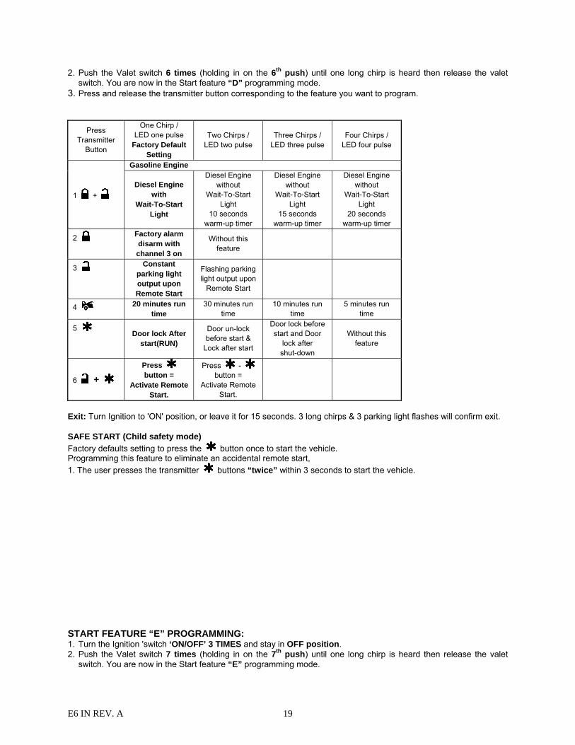
2. Push the Valet switch 6 times (holding in on the 6th push) until one long chirp is heard then release the valet switch. You are now in the Start feature “D” programming mode.
3. Press and release the transmitter button corresponding to the feature you want to program.
Press Transmitter
Button
One Chirp / LED one pulse
Factory Default Setting
Two Chirps / LED two pulse
Three Chirps / LED three pulse
Four Chirps / LED four pulse
1 +
Gasoline Engine
Diesel Engine with
Wait-To-Start Light
Diesel Engine without
Wait-To-Start Light
10 seconds warm-up timer
Diesel Engine without
Wait-To-Start Light
15 seconds warm-up timer
Diesel Engine without
Wait-To-Start Light
20 seconds warm-up timer
2 Factory alarm disarm with channel 3 on
Without this feature
3 Constant parking light output upon Remote Start
Flashing parking light output upon
Remote Start
4 20 minutes run time
30 minutes run time
10 minutes run time
5 minutes run time
5 Door lock After
start(RUN)
Door un-lock before start &
Lock after start
Door lock before start and Door
lock after shut-down
Without this feature
6 +
Press button =
Activate Remote Start.
Press - button =
Activate Remote Start.
Exit: Turn Ignition to 'ON' position, or leave it for 15 seconds. 3 long chirps & 3 parking light flashes will confirm exit. SAFE START (Child safety mode) Factory defaults setting to press the button once to start the vehicle. Programming this feature to eliminate an accidental remote start, 1. The user presses the transmitter buttons “twice” within 3 seconds to start the vehicle. START FEATURE “E” PROGRAMMING: 1. Turn the Ignition 'switch ‘ON/OFF’ 3 TIMES and stay in OFF position. 2. Push the Valet switch 7 times (holding in on the 7th push) until one long chirp is heard then release the valet
switch. You are now in the Start feature “E” programming mode.
E6 IN REV. A 20
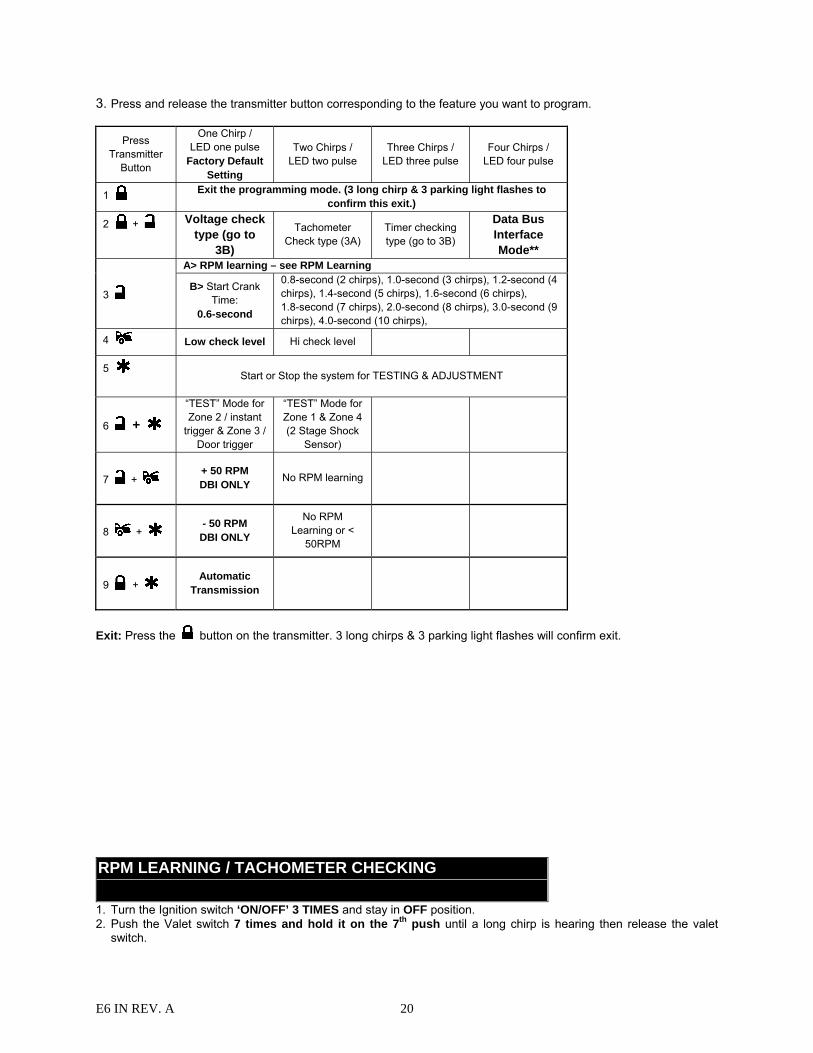
3. Press and release the transmitter button corresponding to the feature you want to program.
Press Transmitter
Button
One Chirp / LED one pulse
Factory Default Setting
Two Chirps / LED two pulse
Three Chirps / LED three pulse
Four Chirps / LED four pulse
1 Exit the programming mode. (3 long chirp & 3 parking light flashes to confirm this exit.)
2 + Voltage check type (go to
3B)
Tachometer Check type (3A)
Timer checking type (go to 3B)
Data Bus Interface Mode**
3
A> RPM learning – see RPM Learning
B> Start Crank Time:
0.6-second
0.8-second (2 chirps), 1.0-second (3 chirps), 1.2-second (4 chirps), 1.4-second (5 chirps), 1.6-second (6 chirps), 1.8-second (7 chirps), 2.0-second (8 chirps), 3.0-second (9 chirps), 4.0-second (10 chirps),
4 Low check level Hi check level
5 Start or Stop the system for TESTING & ADJUSTMENT
6 +
“TEST” Mode for Zone 2 / instant
trigger & Zone 3 / Door trigger
“TEST” Mode for Zone 1 & Zone 4 (2 Stage Shock
Sensor)
7 + + 50 RPM DBI ONLY
No RPM learning
8 + - 50 RPM
DBI ONLY
No RPM Learning or <
50RPM
9 + Automatic
Transmission
Exit: Press the button on the transmitter. 3 long chirps & 3 parking light flashes will confirm exit. RPM LEARNING / TACHOMETER CHECKING TYPE 1. Turn the Ignition switch ‘ON/OFF’ 3 TIMES and stay in OFF position. 2. Push the Valet switch 7 times and hold it on the 7th push until a long chirp is hearing then release the valet
switch.
E6 IN REV. A 21
3. Press and release the transmitter and buttons at the same time once to set the “Tachometer Checking Type”. [2] LED flash, [2] chirp to confirm this setting.
4. Press and release the transmitter button once, [2] LED flash, [2] chirp to indicate your are in features “RPM Learning mode”.
5. Start the vehicle with the key. (While the engine is running, the parking & LED will flash, If don’t, please check tachometer White/Blue wire connection.
6. Press and hold the valet switch for 2 seconds until a long chirp and the LED light constant for two seconds. The RPM signal is learned.
7. Turns off the ignition switch to stop the engine running. Once you complete step 7, you can adjust and test “Check Level” as below:
CHECK LEVEL PROGRAMMING: (TEST and ADJUST) 1. Press button once on the transmitter to start the vehicle. 2. If everything goes well:
a. Press button once on the transmitter to stop engine running. You have been completed this programming successfully.
b. Press button on the transmitter to exit the program mode. There will be 3 long chirps & 3 parking light flashes for confirmation.
3. If the crank time is too long, (Engine already successfully running, but still cranks): a. Press once on the transmitter to stop engine running or press brake pedal.
Press button on the transmitter to set proper “Check Level ” to Low position. [1] LED flash, [1 chirp will confirm this setting
b. Repeat steps 1 – 4 if necessary. 4. If the crank time is too short, (Engine not running, crank stopped before starting):
a. Press button once on the transmitter to stop engine running. Press button on the transmitter to set proper “ Check Level ” to Hi position. [2] LED flash, [2 chirps will confirm this setting
Repeat steps 1 – 4 if necessary. VOLTAGE CHECKING TYPE 1. Turn the Ignition 'switch ‘ON/OFF’ 3 TIMES and stay in OFF position. Default setting 2. Push the Valet switch 7 times and hold it on the 7th push until a long chirp is hearing then release the valet
switch. 3. Press the transmitter and buttons at the same time to set the “Voltage Checking Type”. [1] LED flashes, [1]
chirp to confirm this setting Once you complete step 3, you can adjust and test “Start Timer” as below: START CRANK TIME PROGRAMMING: (TEST and ADJUST) 1. Press button once on the transmitter to start the vehicle. 2. If everything goes well: Wait for 15 seconds:
a. If the engine still running. I. Press button once on the transmitter to stop engine running. You have been completed this programming
successfully. II. Press button on the transmitter to exit the program mode. There will be 3 long chirps & 3 parking light flashes for confirmation.
b. If the engine shuts down after the vehicle has been started. I. Press button once on the transmitter to stop engine running. II. Press button on the transmitter to set “Check Level” to LOW position. [1] LED flash, [1] chirp to confirm this setting III. Repeat steps 1 – 2.
3. If the crank time is too long, (Engine already successfully running, but still cranks): a. Press button once on the transmitter to stop engine running.
E6 IN REV. A 22
b. Press button on the transmitter to set proper “Start Timer”. The chirp & LED pause will confirm entry. (Decrease “Start Timer” is necessary.)
c. Repeat steps 1 – 4 if necessary. 4. If the crank time is too short, (Engine not started, crank time stopped):
a. Press button once on the transmitter to stop engine running. b. Press button on the transmitter to set proper “Start Timer”. The chirp & LED pause will confirm entry.
(Increase “Start Timer ” is necessary.) c. Repeat steps 1 – 4.
Timer Checking Type 1. Turn the Ignition 'switch ‘ON/OFF’ 3 TIMES and stay in OFF position. 2. Push the Valet switch 7 times and hold it on the 7th push until a long chirp is hearing then release the valet
switch. 3. Press the transmitter and buttons at the same time to set the “Timer Checking Type”. [3] LED flashes, [3]
chirps to confirm this setting Once you complete step 3, you can adjust and test “Start Timer” as below: START TIMER PROGRAMMING: (TEST) and ADJUST)While the system is in Start Feature “E” programming mode, 1. Press the button once on the transmitter to start the vehicle. 2. If everything goes well:
a. Press the ' button once on the transmitter to stop engine running. You have been completed this programming successfully.
b. Press button on the transmitter to exit the program mode. There will be 3 long chirps & 3 parking light flashes for confirmation.
3. If the crank time is too long, (Engine already successfully running, but still cranks): a. Press the button once on the transmitter to stop engine running. b. Press the button on the transmitter to set proper “Start Timer”. The chirp & LED pause will confirm entry.
(Decrease “Start Timer” is necessary.) c. Repeat the step1 – 4.
4. If the crank time is too short, (Engine not running, crank stopped before starting): a. Press the button once on the transmitter to stop engine running. b. Press button on the transmitter to set proper “Start Timer”. The chirp & LED pause will confirm entry.
(Increase “Start Timer ” is necessary.) c. Repeat the step1 – 4.
TEST MODE In this test mode, this system can test the Zone 2 (Instant ground trigger), the Zone 3 (Door trigger), and the Zone 1 & Zone 4 (2 stage shock sensor) sensitivity. The installer can save time to test the 2-stage shock sensor sensitivity and sensor without using the traditional arming/disarming procedures to test the sensors. Enter: 1. Turn the Ignition 'switch ‘ON/OFF’ 3 TIMES and stay in OFF position. 2. Push the Valet switch 7 times (holding in on the 7th) until one long chirp is heard then release the valet switch. You
are now in the Start feature ‘”E” programming mode. a. Test the Zone 2 / Instant Ground Trigger & Zone 3 / Door Trigger:
Press and release the transmitter and buttons at the same time once. [1] LED flash, [1] siren/horn chirp to indicate your are in Zone 2 / instant ground trigger and Zone 3 / Door trigger test mode.
Trigger sensor Siren chirps Zone 2 / Instant Ground trigger (H6/17 Blue wire) 2 Zone 3 / Door trigger (H6/15 Green or H6/19 Violet wire) 3
b. Test the Zone 1 & Zone 4 / Two Stage Shock Sensor (Connected to H6 4 Pin Plug):
Press and release the transmitter and buttons at the same time again. [2] LED flash, [2] siren/horn chirps to indicate your are in the shock sensor (connected to H6 4 pin plug) test mode. 1. Activate the warn-away (first stage of the shock sensor / Zone 1), system will emit a short chirp. 2. Activate the full alarm (second stage of the shock sensor / Zone 4), system will emit a long chirp.
E6 IN REV. A 23
3. Continue to test the shock sensor until the proper sensitivity is reached. RETURN TO FACTORY DEFAULT SETTING: 1. Turn the ignition ON then OFF 3 TIMES and stay in OFF position. 2. Push the Valet switch 8 times (holding in on the 8th push) until one long chirp is heard then release the valet switch.
You are now in the “Return To Factory Default Setting” programming mode. ALARM FEATURE ALL RETURNS TO FACTORY DEFAULT SETTING: 3. Press and hold the and buttons at the same time on the transmitter for 6 seconds, there will be a
confirmation six chirps with three long chirps to confirm the system “Alarm Feature A, B, & C Programming” all returns to factory default setting.
START FEATURE ALL RETURNS TO FACTORY DEFAULT SETTING: 4. Press the first, within 3 seconds press and hold the and buttons at the same time on the transmitter
for 6 seconds, there will be a confirmation six chirp with 4 long chirp to confirm the system “Start Feature D & E Programming all returns to factory default setting.
Exit: Turn Ignition to 'ON' position, or leave it for 15 seconds. A 3 long chirps & 3 parking light flashes to confirm exit.
DATA BUS RESET FOR C I 3 INTERFACE 1. Turn the ignition ON then OFF 3 TIMES and stay in OFF position. 2. Push the Valet switch 9 times (holding in on the 9th push) until one long chirp is heard then release the valet
switch. You are now in the “Data Bus Reset Setting” programming mode. Data Bus Reset: 3. Press and hold the and buttons at the same time on the transmitter, there will be a confirmation with
three long chirps to confirm the system has reset the data bus.
TROUBLE SHOOTING There are 5 reasons why the remote start button will not respond from the transmitter. 1. The Black/White Neutral Safety wire is not grounded. Must be grounded to start. 2. Hood Pin switch White/Black wire has a ground present. Must not show ground to start. 3. Brake pedal switch White/Violet has 12 volt present. Must not show 12 volt to start. 4. The system is in Valet mode. 5. The remote start feature programming has not been programmed to start the vehicle. The remote start
must be programmed how to start the vehicle. SHUTDOWN DIAGNOSTICS The unit has the ability to report the cause of the last shutdown of the remote start system.
E6 IN REV. A 24
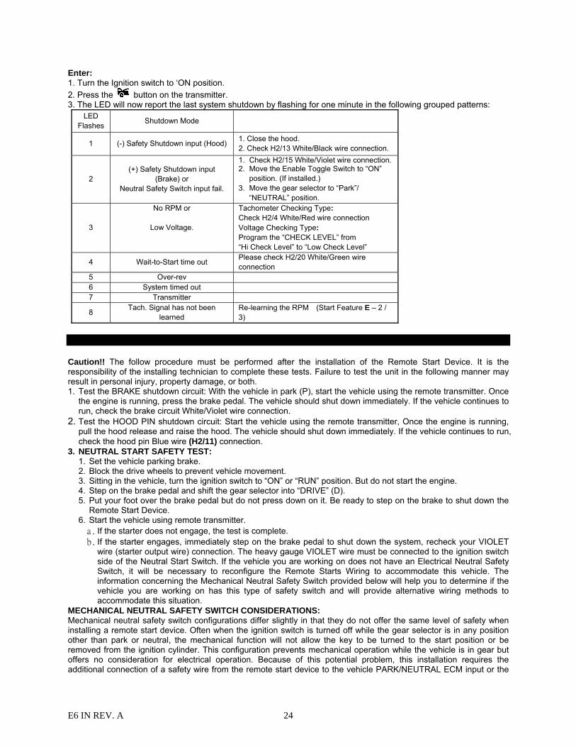
Enter: 1. Turn the Ignition switch to ‘ON position. 2. Press the button on the transmitter. 3. The LED will now report the last system shutdown by flashing for one minute in the following grouped patterns:
LED Flashes Shutdown Mode
1 (-) Safety Shutdown input (Hood) 1. Close the hood. 2. Check H2/13 White/Black wire connection.
2 (+) Safety Shutdown input
(Brake) or Neutral Safety Switch input fail.
1. Check H2/15 White/Violet wire connection. 2. Move the Enable Toggle Switch to “ON”
position. (If installed.) 3. Move the gear selector to “Park”/
“NEUTRAL” position.
3
No RPM or
Low Voltage.
Tachometer Checking Type: Check H2/4 White/Red wire connection Voltage Checking Type: Program the “CHECK LEVEL” from “Hi Check Level” to “Low Check Level”
4 Wait-to-Start time out Please check H2/20 White/Green wire connection
5 Over-rev 6 System timed out 7 Transmitter
8 Tach. Signal has not been learned
Re-learning the RPM (Start Feature E – 2 / 3)
TESTING YOUR INSTALLATION:
Caution!! The follow procedure must be performed after the installation of the Remote Start Device. It is the responsibility of the installing technician to complete these tests. Failure to test the unit in the following manner may result in personal injury, property damage, or both. 1. Test the BRAKE shutdown circuit: With the vehicle in park (P), start the vehicle using the remote transmitter. Once
the engine is running, press the brake pedal. The vehicle should shut down immediately. If the vehicle continues to run, check the brake circuit White/Violet wire connection.
2. Test the HOOD PIN shutdown circuit: Start the vehicle using the remote transmitter, Once the engine is running, pull the hood release and raise the hood. The vehicle should shut down immediately. If the vehicle continues to run, check the hood pin Blue wire (H2/11) connection.
3. NEUTRAL START SAFETY TEST: 1. Set the vehicle parking brake. 2. Block the drive wheels to prevent vehicle movement. 3. Sitting in the vehicle, turn the ignition switch to “ON” or “RUN” position. But do not start the engine. 4. Step on the brake pedal and shift the gear selector into “DRIVE” (D). 5. Put your foot over the brake pedal but do not press down on it. Be ready to step on the brake to shut down the
Remote Start Device. 6. Start the vehicle using remote transmitter. a. If the starter does not engage, the test is complete. b. If the starter engages, immediately step on the brake pedal to shut down the system, recheck your VIOLET
wire (starter output wire) connection. The heavy gauge VIOLET wire must be connected to the ignition switch side of the Neutral Start Switch. If the vehicle you are working on does not have an Electrical Neutral Safety Switch, it will be necessary to reconfigure the Remote Starts Wiring to accommodate this vehicle. The information concerning the Mechanical Neutral Safety Switch provided below will help you to determine if the vehicle you are working on has this type of safety switch and will provide alternative wiring methods to accommodate this situation.
MECHANICAL NEUTRAL SAFETY SWITCH CONSIDERATIONS: Mechanical neutral safety switch configurations differ slightly in that they do not offer the same level of safety when installing a remote start device. Often when the ignition switch is turned off while the gear selector is in any position other than park or neutral, the mechanical function will not allow the key to be turned to the start position or be removed from the ignition cylinder. This configuration prevents mechanical operation while the vehicle is in gear but offers no consideration for electrical operation. Because of this potential problem, this installation requires the additional connection of a safety wire from the remote start device to the vehicle PARK/NEUTRAL ECM input or the
E6 IN REV. A 25
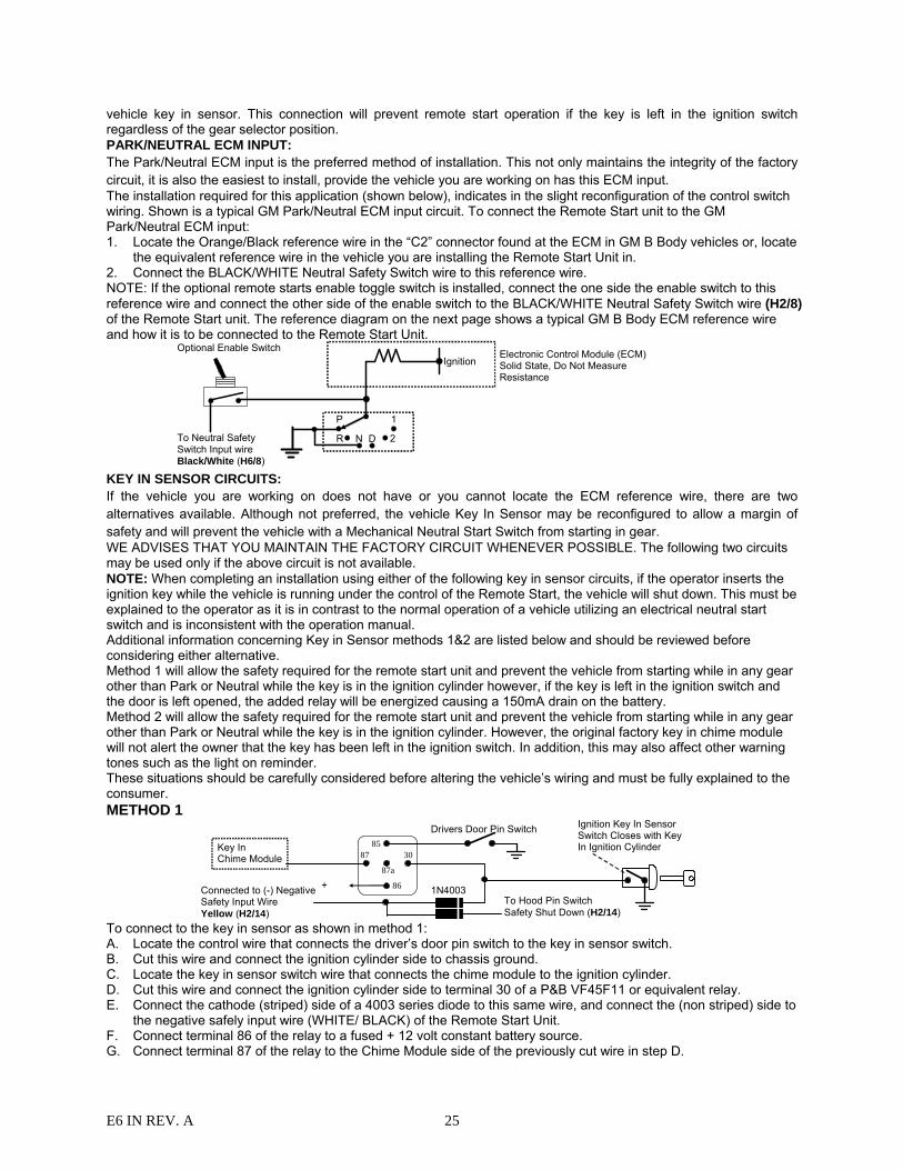
vehicle key in sensor. This connection will prevent remote start operation if the key is left in the ignition switch regardless of the gear selector position. PARK/NEUTRAL ECM INPUT: The Park/Neutral ECM input is the preferred method of installation. This not only maintains the integrity of the factory circuit, it is also the easiest to install, provide the vehicle you are working on has this ECM input. The installation required for this application (shown below), indicates in the slight reconfiguration of the control switch wiring. Shown is a typical GM Park/Neutral ECM input circuit. To connect the Remote Start unit to the GM Park/Neutral ECM input: 1. Locate the Orange/Black reference wire in the “C2” connector found at the ECM in GM B Body vehicles or, locate
the equivalent reference wire in the vehicle you are installing the Remote Start Unit in. 2. Connect the BLACK/WHITE Neutral Safety Switch wire to this reference wire. NOTE: If the optional remote starts enable toggle switch is installed, connect the one side the enable switch to this reference wire and connect the other side of the enable switch to the BLACK/WHITE Neutral Safety Switch wire (H2/8) of the Remote Start unit. The reference diagram on the next page shows a typical GM B Body ECM reference wire and how it is to be connected to the Remote Start Unit.
Ignition
P 1
2DNR
Electronic Control Module (ECM) Solid State, Do Not Measure Resistance
To Neutral Safety Switch Input wire Black/White (H6/8)
Optional Enable Switch
KEY IN SENSOR CIRCUITS: If the vehicle you are working on does not have or you cannot locate the ECM reference wire, there are two alternatives available. Although not preferred, the vehicle Key In Sensor may be reconfigured to allow a margin of safety and will prevent the vehicle with a Mechanical Neutral Start Switch from starting in gear. WE ADVISES THAT YOU MAINTAIN THE FACTORY CIRCUIT WHENEVER POSSIBLE. The following two circuits may be used only if the above circuit is not available. NOTE: When completing an installation using either of the following key in sensor circuits, if the operator inserts the ignition key while the vehicle is running under the control of the Remote Start, the vehicle will shut down. This must be explained to the operator as it is in contrast to the normal operation of a vehicle utilizing an electrical neutral start switch and is inconsistent with the operation manual. Additional information concerning Key in Sensor methods 1&2 are listed below and should be reviewed before considering either alternative. Method 1 will allow the safety required for the remote start unit and prevent the vehicle from starting while in any gear other than Park or Neutral while the key is in the ignition cylinder however, if the key is left in the ignition switch and the door is left opened, the added relay will be energized causing a 150mA drain on the battery. Method 2 will allow the safety required for the remote start unit and prevent the vehicle from starting while in any gear other than Park or Neutral while the key is in the ignition cylinder. However, the original factory key in chime module will not alert the owner that the key has been left in the ignition switch. In addition, this may also affect other warning tones such as the light on reminder. These situations should be carefully considered before altering the vehicle’s wiring and must be fully explained to the consumer. METHOD 1
+ 12 V
Ignition Key In Sensor Switch Closes with Key In Ignition Cylinder
Drivers Door Pin Switch
87a
86
308785Key In
Chime Module
Connected to (-) Negative Safety Input Wire Yellow (H2/14)
To Hood Pin Switch Safety Shut Down (H2/14)
1N4003+
To connect to the key in sensor as shown in method 1: A. Locate the control wire that connects the driver’s door pin switch to the key in sensor switch. B. Cut this wire and connect the ignition cylinder side to chassis ground. C. Locate the key in sensor switch wire that connects the chime module to the ignition cylinder. D. Cut this wire and connect the ignition cylinder side to terminal 30 of a P&B VF45F11 or equivalent relay. E. Connect the cathode (striped) side of a 4003 series diode to this same wire, and connect the (non striped) side to
the negative safely input wire (WHITE/ BLACK) of the Remote Start Unit. F. Connect terminal 86 of the relay to a fused + 12 volt constant battery source. G. Connect terminal 87 of the relay to the Chime Module side of the previously cut wire in step D.
E6 IN REV. A 26
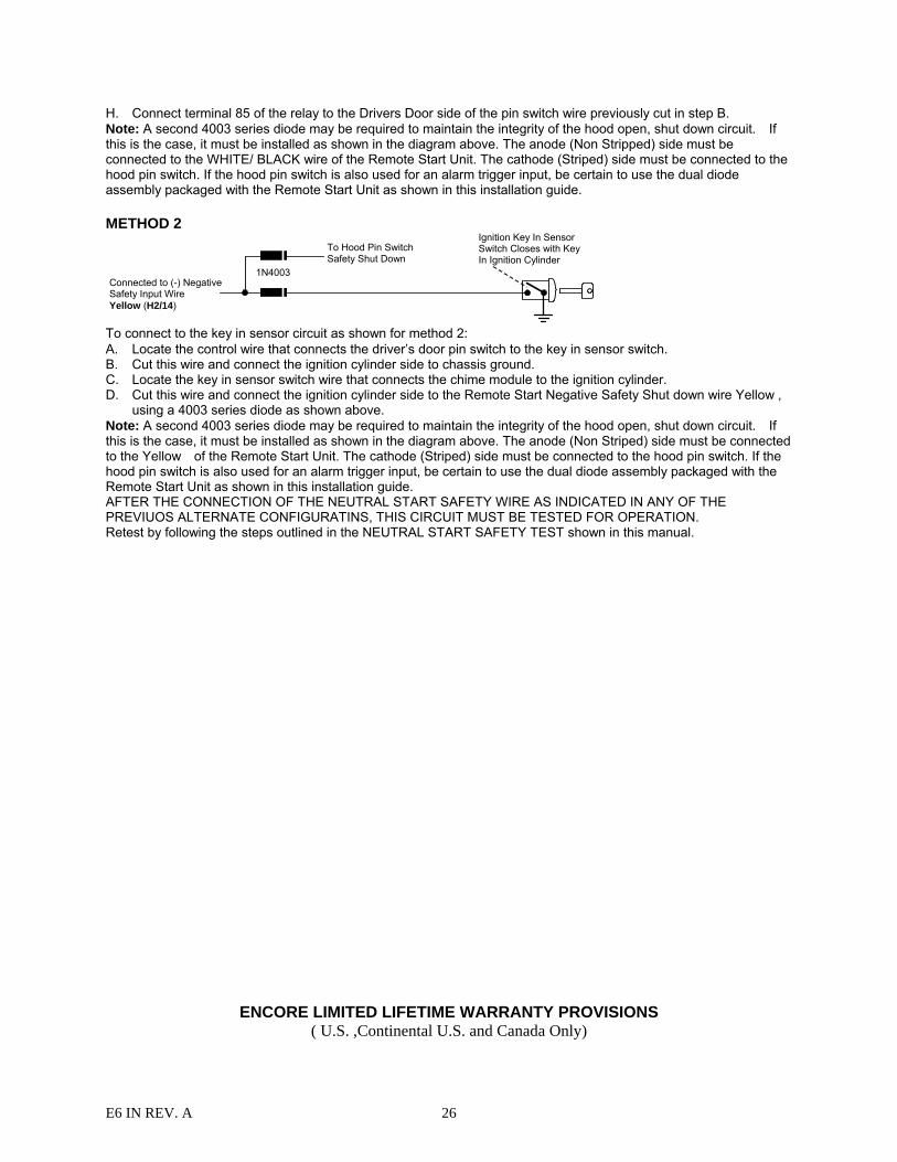
H. Connect terminal 85 of the relay to the Drivers Door side of the pin switch wire previously cut in step B. Note: A second 4003 series diode may be required to maintain the integrity of the hood open, shut down circuit. If this is the case, it must be installed as shown in the diagram above. The anode (Non Stripped) side must be connected to the WHITE/ BLACK wire of the Remote Start Unit. The cathode (Striped) side must be connected to the hood pin switch. If the hood pin switch is also used for an alarm trigger input, be certain to use the dual diode assembly packaged with the Remote Start Unit as shown in this installation guide. METHOD 2 Ignition Key In Sensor
Switch Closes with Key In Ignition Cylinder
Connected to (-) Negative Safety Input Wire Yellow (H2/14)
To Hood Pin Switch Safety Shut Down
1N4003
To connect to the key in sensor circuit as shown for method 2: A. Locate the control wire that connects the driver’s door pin switch to the key in sensor switch. B. Cut this wire and connect the ignition cylinder side to chassis ground. C. Locate the key in sensor switch wire that connects the chime module to the ignition cylinder. D. Cut this wire and connect the ignition cylinder side to the Remote Start Negative Safety Shut down wire Yellow ,
using a 4003 series diode as shown above. Note: A second 4003 series diode may be required to maintain the integrity of the hood open, shut down circuit. If this is the case, it must be installed as shown in the diagram above. The anode (Non Striped) side must be connected to the Yellow of the Remote Start Unit. The cathode (Striped) side must be connected to the hood pin switch. If the hood pin switch is also used for an alarm trigger input, be certain to use the dual diode assembly packaged with the Remote Start Unit as shown in this installation guide. AFTER THE CONNECTION OF THE NEUTRAL START SAFETY WIRE AS INDICATED IN ANY OF THE PREVIUOS ALTERNATE CONFIGURATINS, THIS CIRCUIT MUST BE TESTED FOR OPERATION. Retest by following the steps outlined in the NEUTRAL START SAFETY TEST shown in this manual.
ENCORE LIMITED LIFETIME WARRANTY PROVISIONS ( U.S. ,Continental U.S. and Canada Only)
E6 IN REV. A 27
1. Encore Automotive Systems LLC. WARRANTS that this new unit has been thoroughly inspected
and tested at the factory prior to delivery. Your Encore equipment is guaranteed for “life” to the original purchaser/user of the equipment and the original vehicle in which it was installed by an authorized installer under the following conditions: If the product proves defective (according to Encore’s testing) within the first year, the defective unit may be exchanged or repaired free of charge. “Proof of Purchase” (dated sales receipt) must accompany all warranty returns; otherwise, your return will be rejected and sent back. After one (1) year, the purchaser should ship the unit prepaid to Encore with a money order in the amount of $30.00 to cover shipping and handling charges. Note: The product needs to be registered online at time of installation. To register this product go to, www.encoresautomotivesystems.com .
2. Exclusion to the Limited Lifetime Warranty Provision: All two-way LCD and two-way OLED remote
transceivers are excluded from the Limited Lifetime Warranty noted in paragraph no.1. All two-way LCD and two-way OLED remote transceivers are guaranteed to the original purchaser for a period of one year from date of purchase. If the product proves to be defective within the first year, the defective unit may be exchanged or repaired free of charge. All other provisions stated on this card apply.
3. This WARRANTY will be considered void if the equipment has been misused, neglected, improperly
serviced or installed, altered, dropped or damaged by water, contrary to the Encore OPERATIONS MANUAL. Or, if used with accessories not approved by Encore, which may have contributed to the defect. See note below regarding product installation**.
4. The purchaser’s remedies under this WARRANTY shall be limited to the repair or replacement of
electronic components only. THE FOLLOWING IS NOT COVERED: Damages or deterioration to cases, batteries, covers and cabinets; the cost of repairs, replacement and labor of which shall be borne by the purchaser even if occurring during the WARRANTY period.
5. Any equipment or parts which are claimed to be defective under this WARRANTY must be sent to
the Encore Service center with “proof of purchase” at the purchaser’s expense prior to such return, a Return Authorization Number needs to be obtained. Encore will return the equipment, charges prepaid. Warranty Service can be provided through the dealer where the equipment is originally purchased.
6. Any unexpired WARRANTY shall be applicable to equipment and parts in the possession of the
original purchaser only. 7. THIS WARRANTY IS IN LIEU OF ANY AND ALL OTHER WARRANTIES, EXPRESSED OR
IMPLIED, INCLUDING BUT NOT LIMITED TO ANY WARRANTY OF MERCHANTABILITY OR FITNESS FOR A PARTICULAR PURPOSE.
8. Encore shall not be liable, under the foregoing WARRANTIES or otherwise, for: Any personal injury
or property damage of any kind to the purchaser or property, its employees or agents or anyone else whomsoever resulting directly or indirectly from the use or presence of the equipment or parts; Consequential damages of any kind; any inability of the purchaser to use the equipment.
**IMPORTANT NOTE: Any damages resulting from an installation performed by anyone other than a professional installation technician authorized by Encore will void the product’s Limited Lifetime Warranty.
E6 IN REV. A 28
It is the purchaser’s responsibility to register this product for any future warranty service. Warning: Some batteries may contain Perchlorate What is Perchlorate? Perchlorate is both a naturally occurring and manmade contaminant increasingly found in groundwater, surface water and soil. Most perchlorate manufactured in the U.S. is used as an ingredient in solid fuel for rockets and missiles. In addition, perchlorate-based chemicals are also used in the construction of highway safety flares, fireworks, pyrotechnics, explosives, common batteries, and automobile restraint systems. Perchlorate contamination has been reported in at least 20 states. Perchlorate greatly impacts human health by interfering with iodide uptake into the thyroid gland. In adults, the thyroid gland helps regulate the metabolism by releasing hormones, while in children; the thyroid helps in proper development. Perchlorate is becoming a serious threat to human health and water resources.“Perchlorate Material – Special handling may apply.”For more information, go to http://www.dtsc.ca.gov/hazardouswaste/perchlorate/
Notes :