e830-dtu(2r2-433l) datasheet en v1.0
TRANSCRIPT

1
E830-DTU(2R2-433L)
This manual may be modified based on product upgrade, please refer to the latest version.
All rights to interpret and modify this manual belong to Chengdu Ebyte Electronic Technology Co., Ltd.
User Manual

2
Version Date Description Issued by
1.00 2018/08/12 Initial version huaa
Content
Features.................................................................................................................................................................................................................. 3
1. Quick Start ................................................................................................................................................................................................... 3
1.1 Connection.................................................................................................................................................................................... 3
1.2 Controlling & collecting ........................................................................................................................................................ 6
2. Product Introduction ............................................................................................................................................................................. 7
2.1 General parameters ................................................................................................................................................................. 7
2.2 Size and interface description ........................................................................................................................................... 8
2.3 Reset button description ....................................................................................................................................................10
2.4 Indicator description .............................................................................................................................................................10
2.5 Dial switch description .........................................................................................................................................................10
3. Configuration mode ............................................................................................................................................................................11
4. Following mode......................................................................................................................................................................................11
4.1 Wireless response speed ....................................................................................................................................................11
4.2 Wireless channel ......................................................................................................................................................................12
4.3 Resending times ......................................................................................................................................................................13
5. Collecting mode .....................................................................................................................................................................................13
5.1 Relay maintains all the time ..............................................................................................................................................13
5.2 Relay keeps set time ..............................................................................................................................................................13
6. Modbus .......................................................................................................................................................................................................13
6.1 Default factory settings .......................................................................................................................................................13
6.2 ModBus address table..........................................................................................................................................................14
7. Important Statements.........................................................................................................................................................................17
8. About Us.....................................................................................................................................................................................................17

3
Features
It supports 2-channel switch value input;
It supports 2-channel relay output;
It supports remote transmission of data via 433MHz band;
It supports digital value following, controlling & collecting;
It supports four operation modes: wireless control acquisition, wireless follow-up transmission mode, wireless follow-up
reception mode, configuration mode, selection by dialing switch;
It uses Modbus RTU protocol data processing;
Tap the reset button, press and hold 5s in the wireless control acquisition mode, and the Modbus address restores the default
address 01. Built-in watch-dog enables super stability;
3 double-color indicators indicates operating modes;
The power supply features good over-current, over-voltage, reverse connection protection functions.
1. Quick Start
This chapter is a quick introduction to the E830-DTU (2R2-433L) series. It is recommended that the user system read
this chapter and follow the instructions. It will have a systematic understanding of the module products, and users can also
select the chapters you are interested in to read. For specific details and instructions, please refer to the following sections.
1.1 Connection
1.1.1 Input connection

4
1.1.2 Output connection
1.1.3 RS485 connection
In RS485 communication, please note the matching of A and B lines. If communication is abnormal, 120R matching resistor should be added
between A and B lines.
1.1.4 Following function
Prepare two E830-DTUs (2R2-433L) labeled as Device A and Device B, to ensure that their parameters are the same (factory default
parameters), device A is configured as the transmitting end, and device B i s configured as the receiving end. After the mode is changed, i t
needs to be powered on again.

5
Device A, the transmitter, M1=0, M0=1, repower it on after configurating.
Device B, the receiver, M1=1, M0=0, repower it on after configurating.
Notes: The input channel 1 of device A changes, while the blue light of D1 is on, the relay 1 of device B acts accordingly, and the green light of D1 is on. The input channel 2 of device A changes, while the blue light of D2 is on, the relay 2 of device B acts accordingly, and the green light of D2 is on. In the following mode, only the relay at the receiving end acts when the transmitting end is input, and the relay at the transmitting end does not move.
6
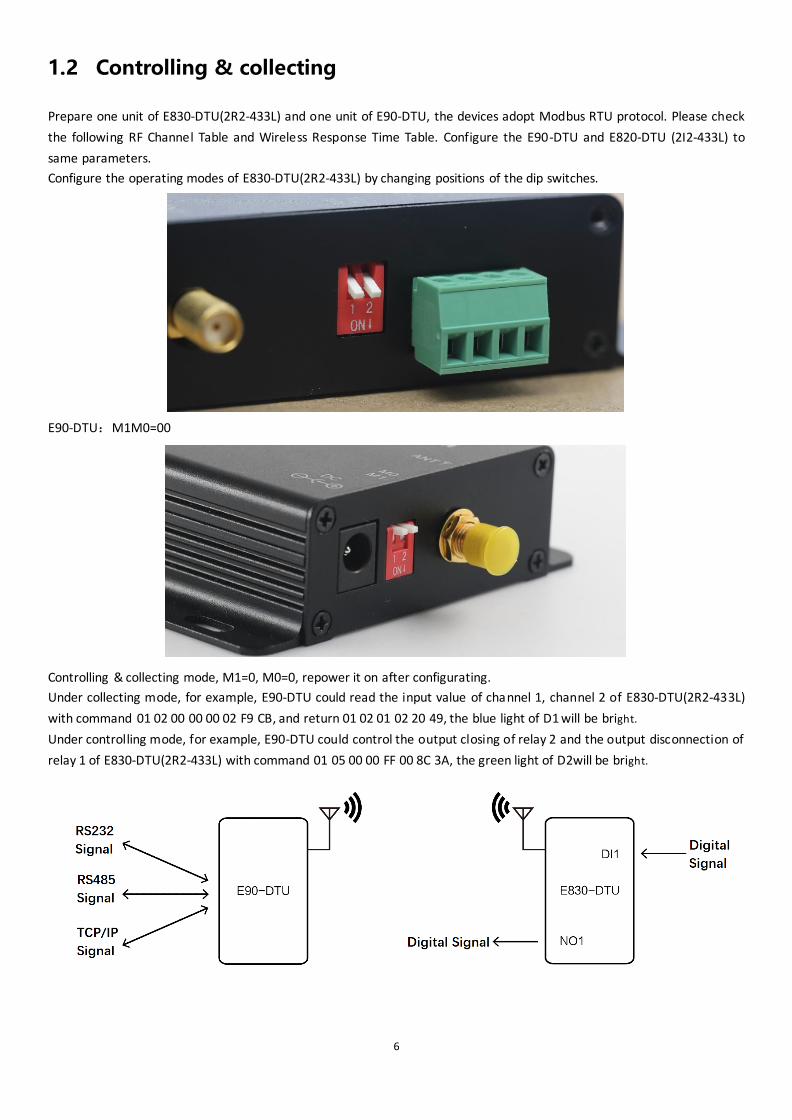
1.2 Controlling & collecting
Prepare one unit of E830-DTU(2R2-433L) and one unit of E90-DTU, the devices adopt Modbus RTU protocol. Please check
the following RF Channel Table and Wireless Response Time Table. Configure the E90-DTU and E820-DTU (2I2-433L) to
same parameters.
Configure the operating modes of E830-DTU(2R2-433L) by changing positions of the dip switches.
E90-DTU:M1M0=00
Controlling & collecting mode, M1=0, M0=0, repower it on after configurating.
Under collecting mode, for example, E90-DTU could read the input value of channel 1, channel 2 of E830-DTU(2R2-433L)
with command 01 02 00 00 00 02 F9 CB, and return 01 02 01 02 20 49, the blue light of D1 will be bright.
Under controlling mode, for example, E90-DTU could control the output closing of relay 2 and the output disconnection of
relay 1 of E830-DTU(2R2-433L) with command 01 05 00 00 FF 00 8C 3A, the green light of D2will be bright.
7
2. Product Introduction
E820-DTU (2I2-433L) is a remote controlling device supporting switch value following, controlling and collecting. It
supports 2-channel switch value input and 2-channel relay output. The communication interface is RS-485(only in
configuration mode) and it supports Modbus RTU protocol. This product is easy to use, It can be widely used in signal
collecting, monitoring and control of industrial field equipment.
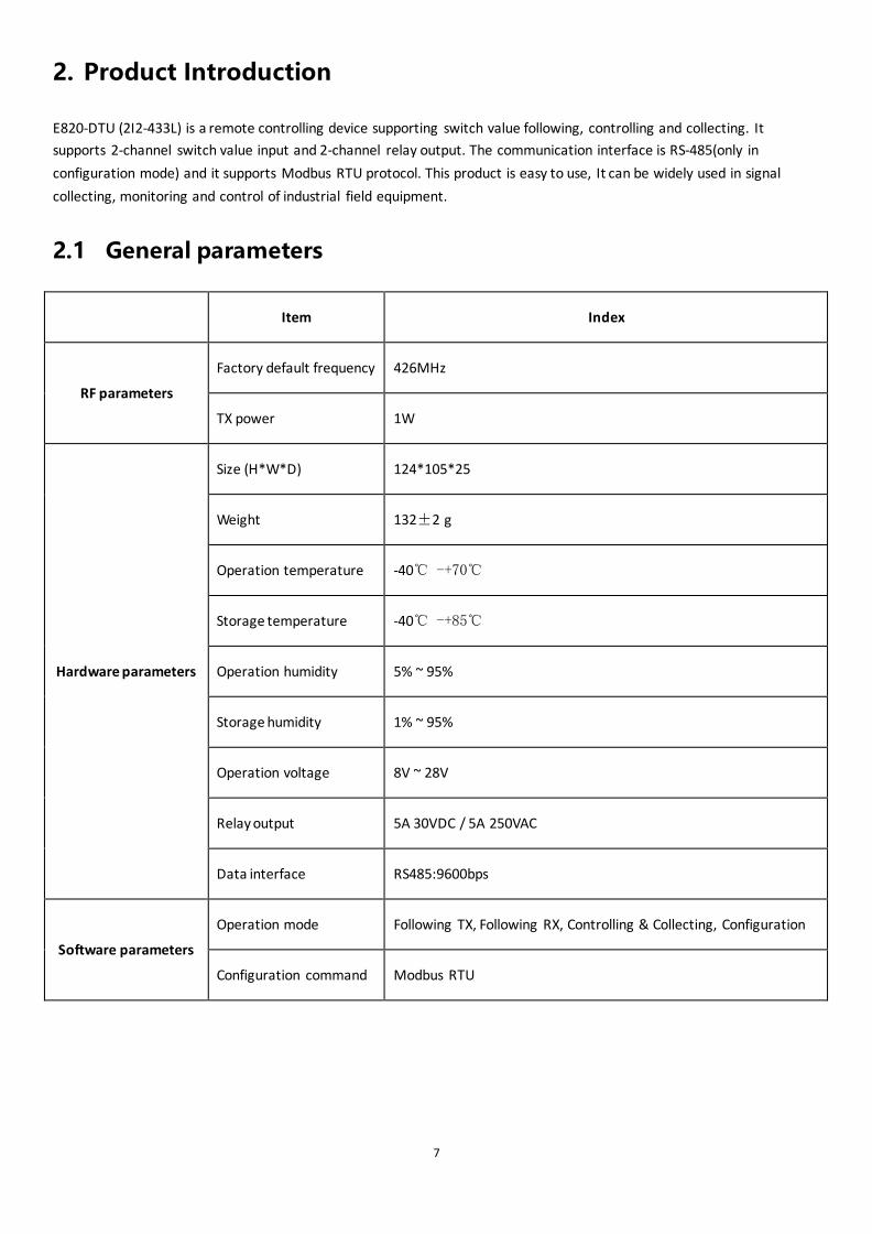
2.1 General parameters
Item Index
RF parameters
Factory default frequency 426MHz
TX power 1W
Hardware parameters
Size (H*W*D) 124*105*25
Weight 132±2 g
Operation temperature -40℃ -+70℃
Storage temperature -40℃ -+85℃
Operation humidity 5% ~ 95%
Storage humidity 1% ~ 95%
Operation voltage 8V ~ 28V
Relay output 5A 30VDC / 5A 250VAC
Data interface RS485:9600bps
Software parameters
Operation mode Following TX, Following RX, Controlling & Collecting, Configuration
Configuration command Modbus RTU
8
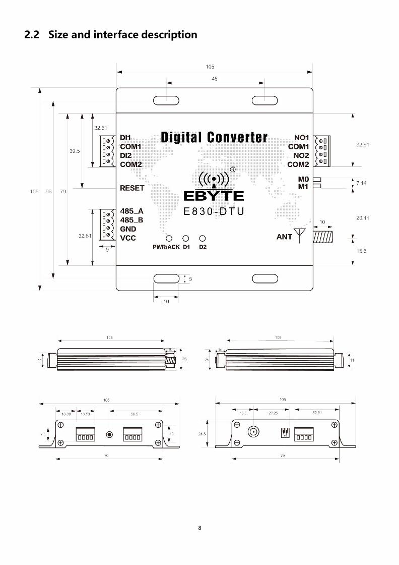
2.2 Size and interface description
9
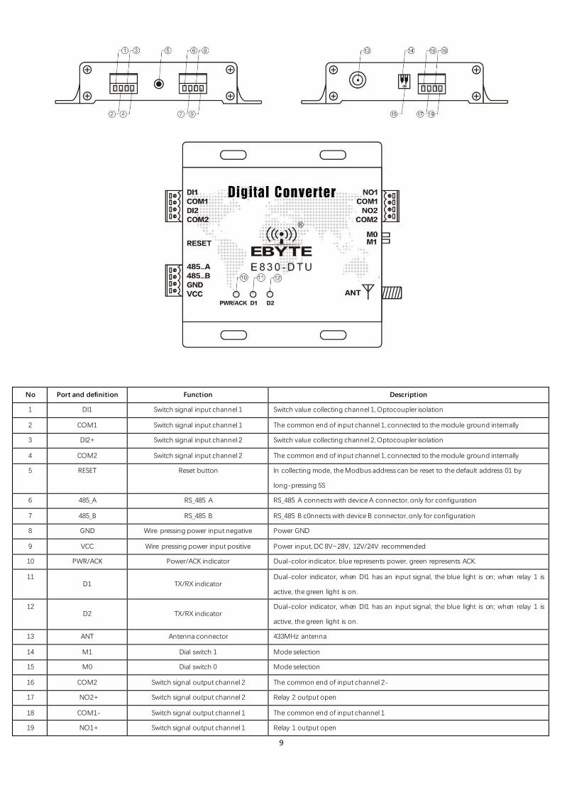
No Port and definition Function Description
1 DI1 Switch signal input channel 1 Switch value collecting channel 1, Optocoupler isolation
2 COM1 Switch signal input channel 1 The common end of input channel 1, connected to the module ground internally
3 DI2+ Switch signal input channel 2 Switch value collecting channel 2, Optocoupler isolation
4 COM2 Switch signal input channel 2 The common end of input channel 1, connected to the module ground internally
5 RESET Reset button In collecting mode, the Modbus address can be reset to the default address 01 by
long-pressing 5S
6 485_A RS_485 A RS_485 A connects with device A connector, only for configuration
7 485_B RS_485 B RS_485 B c0nnects with device B connector, only for configuration
8 GND Wire pressing power input negative Power GND
9 VCC Wire pressing power input positive Power input, DC 8V~28V, 12V/24V recommended
10 PWR/ACK Power/ACK indicator Dual-color indicator, blue represents power, green represents ACK.
11 D1 TX/RX indicator
Dual-color indicator, when DI1 has an input signal, the blue light is on; when relay 1 is
active, the green light is on.
12 D2 TX/RX indicator
Dual-color indicator, when DI1 has an input signal, the blue light is on; when relay 1 is
active, the green light is on.
13 ANT Antenna connector 433MHz antenna
14 M1 Dial switch 1 Mode selection
15 M0 Dial switch 0 Mode selection
16 COM2 Switch signal output channel 2 The common end of input channel 2-
17 NO2+ Switch signal output channel 2 Relay 2 output open
18 COM1- Switch signal output channel 1 The common end of input channel 1
19 NO1+ Switch signal output channel 1 Relay 1 output open
10
Notes:
Ground: it’s recommended to connect the device case to ground.
RS485: RS485 interface will only be used when configuring parameters under configuration mode.
Interface: COM port on the input side and on the output side cannot be mixed.
2.3 Reset button description
Long-pressing for 5 seconds, RST indicator blinks for one time once reset successful. (only valid under following RX,
controlling & collecting, configuration modes, only reset the device address as 0x01H)
2.4 Indicator description
PWR/ACK: Power/ACK indicator
When the DTU is powered on, the power indicator is always on, it is blue; only when the transmitter receives the ACK
returned by the receiver, the dual-color indicator will change from blue to purple and then back to blue. After the color
changes, it indicates that the transmitting end receives the ACK of the receiving end.
D1: Input/Output indicator
Dual-color lamp, when DI1 has input signal, blue light is on; when relay 1 is active, green light is on.
D2: Input/Output indicator
Dual-color lamp, when DI2 has input signal, blue light is on; when relay 2 is active, green light is on.
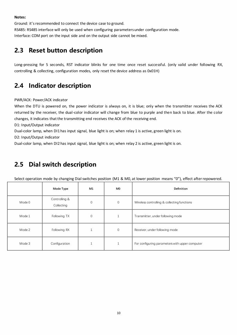
2.5 Dial switch description
Select operation mode by changing Dial switches position (M1 & M0, at lower position means “0”), effect after repowered.
Mode Type M1 M0 Definition
Mode 0 Controlling &
Collecting 0 0 Wireless controlling & collecting functions
Mode 1 Following TX 0 1 Transmitter, under following mode
Mode 2 Following RX 1 0 Receiver, under following mode
Mode 3 Configuration 1 1 For configuring parameters with upper computer

11
3. Configuration mode
Configuration mode (M1M0=11), configuration parameters can be configured by the host computer
Device address: It is the current Modbus address of DTU, the range is 0-248. The smaller the value is, the faster the search
speed of the upper computer is. The larger the value is, the slower the search speed is. When the upper computer is used
to change the address, the address must be searched again to change other parameters.
4. Following mode
4.1 Wireless response speed
It is the time when the data is input from the input port and then transmitted to the DTU output relay through the wireless
module. A total of 5 levels, the smaller the time, the faster the speed, the smaller the delay, the closer the distance.

12
E830-DTU wireless response speed E90-DTU air data rate
1 320ms 1200bps
2 200ms 2400bps (default)
3 120ms (default) 4800bps
4 100ms 9600bps
5 80ms 19200bps
4.2 Wireless channel
It is the frequency of DTU wireless communication, a total of 0-31 channels, the corresponding frequency point is as
follows:
E830-DTU wireless channel E90-DTU drequency and address
Frequency Channel Channel Address
410 MHz 0 0 0000
411 MHz 1 1 0101
412 MHz 2 2 0202
439MHz 29 29 1D1D
440MHz 30 30 1E1E
441MHz 31 31 1F1F
E90-DTU address conversion method: first change the decimal channel to a hexadecimal value, and then set the high and low bits of the
address to this value. For example, if the E830 channel is 16, then the E90 parameter needs to set the channel to 16 (corresponding to
hexadecimal 0x10), then the address high and low bits are all set to 10, that is, the address is 1010. Figure:
13
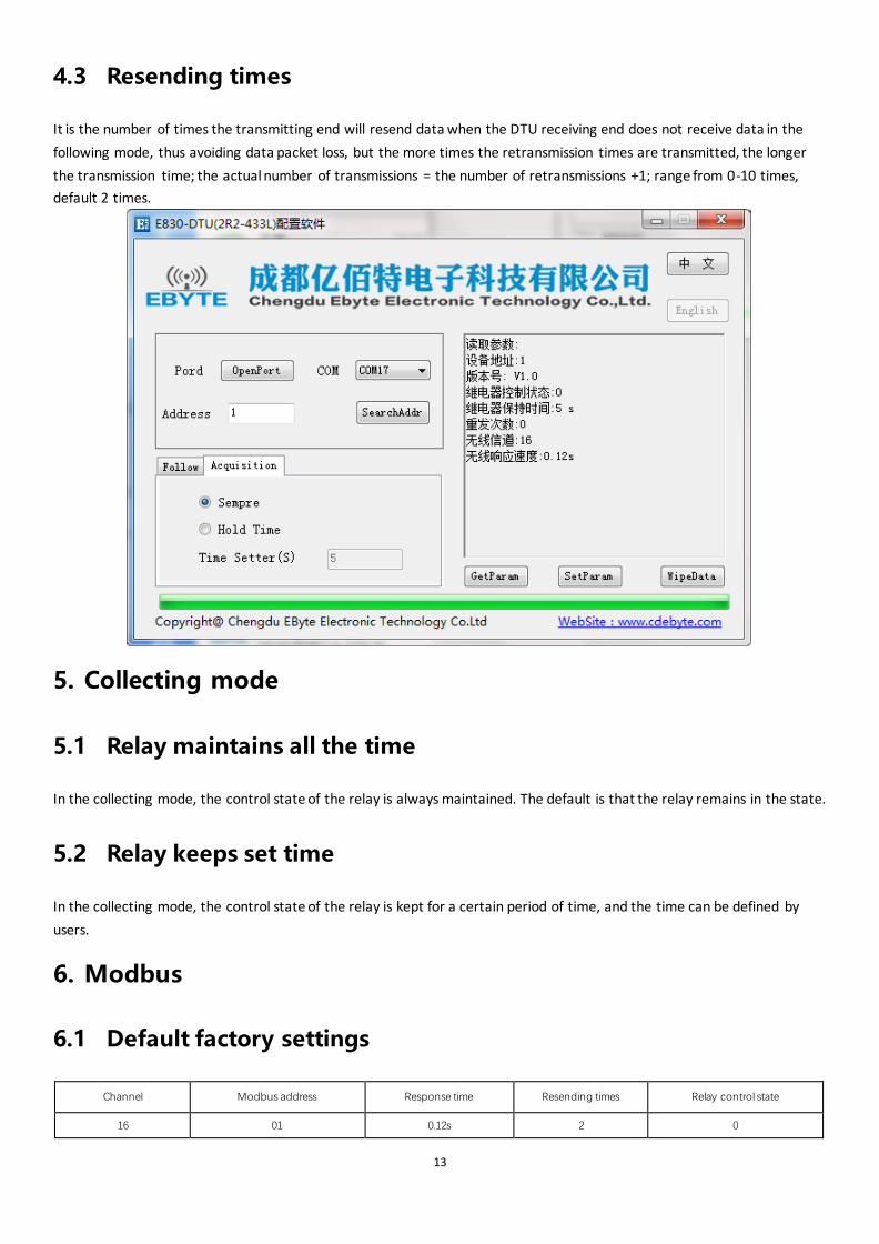
4.3 Resending times
It is the number of times the transmitting end will resend data when the DTU receiving end does not receive data in the
following mode, thus avoiding data packet loss, but the more times the retransmission times are transmitted, the longer
the transmission time; the actual number of transmissions = the number of retransmissions +1; range from 0-10 times,
default 2 times.
5. Collecting mode
5.1 Relay maintains all the time
In the collecting mode, the control state of the relay is always maintained. The default is that the relay remains in the state.
5.2 Relay keeps set time
In the collecting mode, the control state of the relay is kept for a certain period of time, and the time can be defined by
users.
6. Modbus
6.1 Default factory settings
Channel Modbus address Response time Resending times Relay control state
16 01 0.12s 2 0

14
6.2 ModBus address table
(1) Coil read and write instructions
Address table(function code:0x01H、0x05H、0x0FH)
Address Parameter Read/Write Min Max Instruction
00001 NO1 Read/Write 0x0000 0xFF00 Read/write the state of relay 1
00002 NO2 Read/Write 0x0000 0xFF00 Read/write the state of relay 1
Note: When sending a modbus command, the address in the table needs to be reduced by one.
E.g. 1: Use the 01 function code to read the coil output state. For example, read the output ports NO1 and NO2 as follows:
01 01 00 00 00 02 bd cb
Device ModBus address Function code Initial address Number of coils CRC check code
Return value:
01 01 01 02 D0 49
Device ModBus address Function code Data length Coil value CRC check code
Sending command: 01 01 00 00 00 02 bd cb
Return data: 01 01 01 02 D0 49
In the return value, the coil value is 02, corresponding to the binary bit 0000 0010, 1 means the relay output is closed, and
0 means the relay output is open. Bit0 is 0, which means that the relay output NO1 is open; bit1 is 1, which means the
relay output NO2 is closed.
E.g 2: Write an output coil using the 05 function code, for example, let the NO1 relay output close, send the command as
follows:
01 05 00 00 FF 00 8C 3A
Device ModBus address Function code Address Write value CRC check code
Return value:
01 05 00 00 FF 00 8C 3A
Device ModBus address Function code Address Write value CRC check code
Sending command: 01 05 00 00 FF 00 8C 3A
Return data: 01 05 00 00 FF 00 8C 3A
When sending command, the write value FF 00 stands for ON, that is, the relay is closed; the write value 00 00 stands for
OFF, that is, the relay is open.
E.g 3: Write the two output coils using the 0F function code. For example, let the NO2 relay output close and the NO1 relay
output open. Sending command is as follows:
01 0F 00 00 00 02 01 02 5F 56
Device ModBus address Function code Initial address Number of coils Data length Write value CRC check code

15
Return value:
01 0F 00 00 00 02 D4 0A
Device ModBus address Function code Initial address Number of coils CRC check code
Sending command: 01 0F 00 00 00 02 01 02 5F 56
Return data: 01 0F 00 00 00 02 D4 0A
When sending command, the write value 02 corresponds to binary 0000 0010, bit0 is 0, which means OFF, that is, the relay
N01 is openf; bit1 is 1, which means ON, that is, the relay N02 is closed.
(2) Discrete value address table
Discrete value address table(function code:0x02H)
Address Parameter Read/Write Min Max Instruction
10001 D I 1 Read only 0 1 Read the state of digital input channel 1
10002 D I 2 Read only 0 1 Read the state of digital input channel 2
Note: When sending a modbus command, the address in the table needs to be reduced by one.
E.g. 1: Use the 02 function code to read the discrete value input, for example, read DI2, DI1 switch input, send the
command as follows:
01 02 00 00 00 02 F9 CB
Device ModBus address Function code Initial address Number of coils CRC check code
Return value:
01 02 01 02 20 49
Device ModBus address Function code Data length Input state CRC check code
Sending command: 01 02 00 00 00 02 F9 CB
Return data: 01 02 01 02 20 49
In the return data, the input state is 02, corresponding to binary 0000 0010, bit0 is 0, which means disconnected, that is,
the digital input DI1 is open; bit1 is 1, which means closed, that is, the digital input DI2 is closed.
(3) Register address table
Register address table(function code:0x03H、0x06H、0x10H)
40033 ModBus address 2 Read/Write 0 248 Address
40034 Relay control state setting 2 Read/Write 0 1 0 (default), the relay is always maintained;
1, the relay remains setting time.
40035 Relay holding time setting 2 Read/Write 1 1000 Valid when the relay state is 1, default 5S
40036 Resending times 2 Read/Write 0 10 Default 2 times
40037 Wireless channel 2 Read/Write 0 31 Wireless channel
40038 Wireless response time 2 Read/Write 0 4 Default 2, refer to wireless response time description
40039 Device version 2 Read 0 65535 Device version information
Note: 1. When sending a modbus command, the address in the table needs to be reduced by one.
2. The 40034, 40035 register setting values are valid only in the controlling and collecting mode, and the 40036
register setting values are valid only in the following mode.
3. 40039 register only read, so only support 03H function code, do not support 06H, 10H function code.
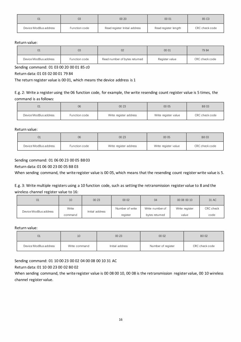
E.g. 1: Use the 03 function code to read the register value, for example, read the Modbus address register. The command is
as follows:
16
01 03 00 20 00 01 85 C0
Device ModBus address Function code Read register Initial address Read register length CRC check code
Return value:
01 03 02 00 01 79 84
Device ModBus address Function code Read number of bytes returned Register value CRC check code
Sending command: 01 03 00 20 00 01 85 c0
Return data: 01 03 02 00 01 79 84
The return register value is 00 01, which means the device address is 1
E.g. 2: Write a register using the 06 function code, for example, the write resending count register value is 5 times, the
command is as follows:
01 06 00 23 00 05 B8 03
Device ModBus address Function code Write register address Write register value CRC check code
Return value:
01 06 00 23 00 05 B8 03
Device ModBus address Function code Write register address Write register value CRC check code
Sending command: 01 06 00 23 00 05 B8 03
Return data: 01 06 00 23 00 05 B8 03
When sending command, the write register value is 00 05, which means that the resending count register write value is 5.
E.g. 3: Write multiple registers using a 10 function code, such as setting the retransmission register value to 8 and the
wireless channel register value to 16:
01 10 00 23 00 02 04 00 08 00 10 31 AC
Device ModBus address Write
command Initial address
Number of write
register
Write number of
bytes returned
Write register
value
CRC check
code
Return value:
01 10 00 23 00 02 B0 02
Device ModBus address Write command Initial address Number of register CRC check code
Sending command: 01 10 00 23 00 02 04 00 08 00 10 31 AC
Return data: 01 10 00 23 00 02 B0 02
When sending command, the write register value is 00 08 00 10, 00 08 is the retransmission register value, 00 10 wireless
channel register value.
17
7. Important Statements
EBYTE reserves the right of final interpretation and modification of all the contents in this manual.
As the hardware and software products continuously improving, this manual may subject to change without notice, please
refer to the latest version.
Users who use this product need to pay attention to the product dynamics on the official website so that users can get the
latest information of this product in time.
8. About Us
EBYTE after-sales technical support: [email protected]
For file download and more product information, please visit: www.ebyte.com/en
Thank you for using the CDEBYTE products! Any questions or suggestions, please contact: [email protected]
Tel: +86-28-61399028 ext. 812
Fax: 028-64146160
Web: www.cdebyte.com/en/
Address: Innovation Center D347, 4# XI-XIN Road, Chengdu, Sichuan, China