ea330-e4 series (engusa)-9y111-10181 · ea330-e4, wsm information i-1 1. safety first...
TRANSCRIPT

WORKSHOP MANUALDIESEL ENGINE
EA330-E4 SERIES
KiSC issued 05, 2015 A

TO THE READER
This Workshop Manual tells the servicing personnel about the mechanism, servicing andmaintenance of the EA330-E4. It contains 4 parts: "Information", "General", "Mechanism" and"Servicing".
InformationThis section primarily contains information below.
• Safety First• Specification• Performance Curve• Dimension
GeneralThis section primarily contains information below.
• Engine Identification• General Precautions• Maintenance Check List• Check and Maintenance• Special Tools
MechanismThis section contains information on the structure and the function of the unit. Before you continue
with the subsequent sections, make sure that you read this section.Refer to the latest version of Workshop Manual (Code No. 9Y021-01870) for the diesel engine
mechanism that this workshop manual does not include.
ServicingThis section primarily contains information below.
• Troubleshooting• Servicing Specifications• Tightening Torques• Checking, Disassembling and Servicing
All illustrations, photographs and specifications contained in this manual are of the newestinformation available at the time of publication.
KUBOTA reserves the right to change all information at any time without notice.Since this manual includes many models, information or illustrations and photographs can show
more than one model.
December, 2013© KUBOTA Corporation 2013
KiSC issued 05, 2015 A

Record of Revisions
For pdf, use search function Search word to find all the revised locations.
Last digit of the
Code No.
Issue month
Main Revised Point and Corrective Measures Search wordReference
Page
1 2015.05 Change the Adjusting Injection Timing to Replacing Injection pump. 1-S19
KiSC issued 05, 2015 A

I INFORMATION
KiSC issued 05, 2015 A

CONTENTS
1. SAFETY FIRST .............................................................................................................................. I-12. SPECIFICATIONS.......................................................................................................................... I-43. PERFORMANCE CURVES............................................................................................................ I-54. DIMENSIONS................................................................................................................................. I-6
INFORMATION
KiSC issued 05, 2015 A

INFORMATIONEA330-E4, WSM
I-1
1. SAFETY FIRST
WSM000001INI0001US1
BEFORE YOU START SERVICE
• Read all instructions and safety instructions in thismanual and on your engine safety decals.
• Clean the work area and engine.• Park the machine on a stable and level ground.• Let the temperature of the engine decrease before
you start a job.• Stop the engine, then remove the key.• Disconnect the battery negative cable.• Hang a "DO NOT OPERATE" tag in the operator
station.WSM000001INI0002US0
START SAFELY
• Do not do the procedures below when you start theengine.– short across starter terminals– bypass the safety start switch
• Do not make unauthorized modifications to theengine. This can cause damage and decrease theengine life.
WSM000001INI0003US0
SAFETY FIRST• This symbol, the industry's "Safety Alert Symbol", is used throughout this manual and on labels on the
machine itself to warn of the possibility of personal injury. Read these instructions carefully.• It is essential that you read the instructions and safety regulations before you try to repair or use this
unit.
DANGER• Indicates an imminently hazardous situation which, if not avoided, will result in death or serious injury.
WARNING• Indicates a potentially hazardous situation which, if not avoided, could result in death or serious injury.
CAUTION• Indicates a potentially hazardous situation which, if not avoided, could result in minor or moderate
injury.
IMPORTANT• Indicates that equipment or property damage could result if instructions are not followed.
NOTE• Gives helpful information.
KiSC issued 05, 2015 A

INFORMATIONEA330-E4, WSM
I-2
OPERATE SAFELY
• Do not use the machine after you consume alcoholor medication or when you are tired.
• Put on applicable clothing and safety equipment.• Use applicable tools only. Do not use alternative
tools or parts.• When 2 or more persons do servicing, make sure
that you do it safely.• Do not touch the hot parts or parts that turn when the
engine operates.• Do not remove the radiator cap when the engine
operates, or immediately after it stops. If not, hotwater can spout out from the radiator. Only removethe radiator cap when it is at a sufficiently lowtemperature to touch with bare hands. Slowly loosenthe cap to release the pressure before you remove itfully.
• Released fluid (fuel or hydraulic oil) under pressurecan cause damage to the skin and cause seriousinjury. Release the pressure before you disconnecthydraulic or fuel lines. Tighten all connections beforeyou apply the pressure.
• Do not open a fuel system under high pressure.The fluid under high pressure that stays in fuel linescan cause serious injury. Do not disconnect or repairthe fuel lines, sensors, or any other componentsbetween the fuel pump and injectors on engines witha common rail fuel system under high pressure.
• Put on an applicable ear protective device (earmuffsor earplugs) to prevent injury against loud noises.
• Be careful about electric shock. The enginegenerates a high voltage of more than DC100 V inthe ECU and is applied to the injector.
WSM000001INI0004US0
PREVENT A FIRE
• Fuel is very flammable and explosive under someconditions. Do not smoke or let flames or sparks inyour work area.
• To prevent sparks from an accidental short circuit,always disconnect the battery negative cable firstand connect it last.
• The battery gas can cause an explosion. Keep thesparks and open flame away from the top of battery,especially when you charge the battery.
• Make sure that you do not spill fuel on the engine.WSM000001INI0005US0
KiSC issued 05, 2015 A

INFORMATIONEA330-E4, WSM
I-3
KEEP A GOOD AIRFLOW IN THE WORK AREA
• If the engine is in operation, make sure that the areahas good airflow. Do not operate the engine in aclosed area. The exhaust gas contains poisonouscarbon monoxide.
WSM000001INI0006US0
DISCARD FLUIDS CORRECTLY
• Do not discard fluids on the ground, down the drain,into a stream, pond, or lake. Obey relatedenvironmental protection regulations when youdiscard oil, fuel, coolant, electrolyte and otherdangerous waste.
WSM000001INI0007US0
PREVENT ACID BURNS
• Keep electrolyte away from your eyes, hands andclothing. Sulfuric acid in battery electrolyte ispoisonous and it can burn your skin and clothing andcause blindness. If you spill electrolyte on yourself,clean yourself with water, and get medical aidimmediately.
WSM000001INI0008US0
PREPARE FOR EMERGENCIES
• Keep a first aid kit and fire extinguisher ready at alltimes.
• Keep the emergency contact telephone numbersnear your telephone at all times.
WSM000001INI0009US0
KiSC issued 05, 2015 A

INFORMATIONEA330-E4, WSM
I-4
2. SPECIFICATIONS
*Conversion Formula: HP=0.746 kW, PS=0.7355 kW9Y1211018INI0001US0
Model EA330-E4-NB1 EA330-E4-NB1-APU-1 EA330-E4-NB1-SCS-1
Number of Cylinder 1
Engine Type Horizontal, water-cooled, 4-cycle diesel engine
Bore × Stroke 77.0 mm × 70.0 mm (3.03 in × 2.76 in.)
Displacement 325 cc (19.8 cu.in.)
Brake HorsepowerSAE Intermittent 5.15 kW (6.91 HP) / 3000 min-1 (rpm)
5.76 kW (7.72 HP) /3000 min-1 (rpm)
SAE Continuous 4.4 kW (5.9 HP) / 3000 min-1 (rpm)4.8 kW (6.4 HP) /3000 min-1 (rpm)
Maximum Bare Speed 3220 min-1 (rpm)
Minimum Bare Idling Speed 1300 min-1 (rpm)
Combustion Chamber Spherical type (TVCS)
Fuel Injection Pump Bosch K type mini pump
Governor Mechanical all speed governor
Direction of Rotation Counter-clockwise (Viewed from flywheel side)
Injection Nozzle DN-PD Mini Nozzle
Injection Timing 0.445 rad (25.5 °) Before T.D.C.
Injection Pressure 13.73 MPa (140.0 kgf/cm2, 1991 psi)
Compression Ratio 24
Lubricating System Forced Lubrication by Trochoid Pump
Cooling System Radiator –
Starting System Electric Starting with Starter
Starting Motor 12 V, 0.8 kW
Starting Support Device By glow plug in combustion chamber
EGR None
Battery 12V, 28 AH equivalent
Charging Alternator 12V, 60W
Fuel No. 2-D S500 or S15, See page G-6
Lubricating OilClass CF lubricating oil as per API classification is recommended.
For details on recommended lubricating oils. (see page G-6)
Lubricating Oil Capacity 1.3 L (0.34 U.S.gals)
Coolant Capacity 1.2 L (0.32 U.S.gals) –
Fuel Tank Capacity 4.8 L (1.3 U.S.gals) –
Weight (Dry) 54.0 kg (119 lbs) 43.0 kg (94.8 lbs) 39.0 kg (86.0 lbs)
KiSC issued 05, 2015 A

INFORMATIONEA330-E4, WSM
I-5
3. PERFORMANCE CURVES
NOTE• Each performance curves obtained in accordance with SAE J816b are corrected to 760 mm Hg
(29.9 in.Hg), 20 °C (68 °F) 60 % humidity.9Y1211018INI0002US0
(1) Intermittent Torque (2) Brake Horse Power (Intermittent)
(3) Fuel Consumption (4) Brake Horse Power (Continuous)
KiSC issued 05, 2015 A

INFORMATIONEA330-E4, WSM
I-6
4. DIMENSIONSEA330-E4-NB1
9Y1211018INI0003US0
A 311.5 mm (12.26 in.)
B 138 mm (5.43 in.)
C 173.5 mm (6.831 in.)
D 326 mm dia. (12.8 in. dia.)
E 64 mm (2.5 in.)
F 46 mm (1.8 in.)
G 567.7 mm (22.35 in.)
H 335 mm (13.2 in.)
I 232.7 mm (9.161 in.)
J 457 mm (18.0 in.)
K 326 mm (12.8 in.)
L 125 mm (4.92 in.)
M 451 mm (17.8 in.)
N 160 mm (6.30 in.)
O 125 mm (4.92 in.)
P 317 mm (12.5 in.)
Q 163 mm (6.42 in.)
KiSC issued 05, 2015 A

INFORMATIONEA330-E4, WSM
I-7
EA330-E4-NB1-APU-1
9Y1211018INI0004US0
A 303.5 mm (11.95 in.)
B 130 mm (5.12 in.)
C 173.5 mm (6.831 in.)
D 64 mm (2.5 in.)
E 46 mm (1.8 in.)
F 485 mm (19.1 in.)
G 317 mm (12.5 in.)
H 168 mm (6.61 in.)
I 400 mm (15.7 in.)
J 304 mm (12.0 in.)
K 125 mm (4.92 in.)
L 429 mm (16.9 in.)
M 160 mm (6.30 in.)
N 125 mm (4.92 in.)
KiSC issued 05, 2015 A

INFORMATIONEA330-E4, WSM
I-8
EA330-E4-NB1-SCS-1
9Y1211018INI0005US0
A 303.5 mm (11.95 in.)
B 130 mm (5.12 in.)
C 173.5 mm (6.831 in.)
D 64 mm (2.5 in.)
E 46 mm (1.8 in.)
F 485 mm (19.1 in.)
G 317 mm (12.5 in.)
H 168 mm (6.61 in.)
I 221 mm (8.70 in.)
J 216.8 mm (8.535 in.)
K 125 mm (4.92 in.)
L 341.8 mm (13.46 in.)
M 160 mm (6.30 in.)
N 125 mm (4.92 in.)
KiSC issued 05, 2015 A

INFORMATIONEA330-E4, WSM
I-9
Pulley Shaft (EA330-E4-NB1, EA330-E4-NB1-APU-1, EA330-E4-NB1-SCS-1)
9Y1211018INI0006US0
V-Pulley
9Y1211018INI0007US0
Flywheel
9Y1211018INI0008US0
No. 19501-8451-0
A 9.525 to 9.575 mm (0.3750 to 0.3769 in.)
B36.487 to 36.512 mm dia.(1.4365 to 1.4374 in. dia.)
C 88.9 mm (3.50 in.)
D 66.60 to 66.90 mm (2.622 to 2.633 in.)
E 3 Through holes-9.0 mm dia. (0.35 in. dia.)
F 128.9 mm (5.075 in.)
G 116 mm dia. (4.57 in. dia.)
H 138 mm dia. (5.43 in. dia.)
(1) Key
No. 19704-8401-0
A 130 mm dia. (5.12 in. dia.)
B 53 mm (2.1 in.)
C 44 mm (1.7 in.)
D 10 mm (0.39 in.)
A 3 Screw holes - Screw dia. size 8.0 mm (0.31 in.)
B 116 mm dia. (4.57 in. dia.)
C97.000 to 97.035 mm dia.(3.8189 to 3.8202 in. dia.)
D 16.8 to 17.2 mm (0.662 to 0.677 in.)
KiSC issued 05, 2015 A

G GENERAL
KiSC issued 05, 2015 A

CONTENTS
1. ENGINE IDENTIFICATION .......................................................................................................... G-1[1] MODEL NAME AND ENGINE SERIAL NUMBER.................................................................. G-1[2] E4 ENGINE ............................................................................................................................ G-3
2. GENERAL PRECAUTIONS.......................................................................................................... G-43. MAINTENANCE CHECK LIST ..................................................................................................... G-54. CHECK AND MAINTENANCE ..................................................................................................... G-7
[1] DAILY CHECK LIST ............................................................................................................... G-7[2] CHECK POINT OF EVERY 50 HOURS................................................................................. G-8[3] CHECK POINT OF EVERY 100 HOURS............................................................................... G-8
5. SPECIAL TOOLS ....................................................................................................................... G-10
GENERAL
KiSC issued 05, 2015 A

GENERALEA330-E4, WSM
G-1
1. ENGINE IDENTIFICATION[1] MODEL NAME AND ENGINE SERIAL NUMBER
When contacting the manufacture, always specify your enginemodel name and serial number.
The engine model and its serial number need to be identifiedbefore the engine can be serviced or parts replaced. Engine Serial Number
The engine serial number is an identified number for the engine.It is marked after the engine model name.
It indicates month and year of manufacture as follows.Engine Series
Production Year
(To be continued)
Number or Alphabet
SeriesNumber or Alphabet
Series
1 05 (include: WG) 7 03
2 V3 8 07
3 08 A EA, RK
4 SM (include: WG) B03 (KET
Production)
5Air Cooled Gasoline
CV3, 07 (KEW Production)
6GZ, OC, AC, EA,
E
Alphabet or Number
YearAlphabet or
NumberYear
1 2001 F 2015
2 2002 G 2016
3 2003 H 2017
4 2004 J 2018
5 2005 K 2019
6 2006 L 2020
7 2007 M 2021
8 2008 N 2022
9 2009 P 2023
A 2010 R 2024
B 2011 S 2025
C 2012 T 2026
D 2013 V 2027
E 2014
(1) Engine Model(2) Serial Number
(3) Emission Label(4) Engine Label
KiSC issued 05, 2015 A

GENERALEA330-E4, WSM
G-2
(Continued)Production Month and Lot Number
* Alphabetical letters "I" and "O" are not used.
e.g. EA330(a)
- 6 (b)
D(c)
B (d)
A001(e)
9Y1211018GEG0001US0
Month Engine Lot Number
January A0001 ~ A9999 B0001 ~
February C0001 ~ C9999 D0001 ~
March E0001 ~ E9999 F0001 ~
April G0001 ~ G9999 H0001 ~
May J0001 ~ J9999 K0001 ~
June L0001 ~ L9999 M0001 ~
July N0001 ~ N9999 P0001 ~
August Q0001 ~ Q9999 R0001 ~
September S0001 ~ S9999 T0001 ~
October U0001 ~ U9999 V0001 ~
November W0001 ~ W9999 X0001 ~
December Y0001 ~ Y9999 Z0001 ~
(a) EA330: Engine Model Name(b) 6: Engine Series (EA series)(c) D: Production Year (2013)(d) B: Production Month (January)(e) A001: Lot Number: (0001 ~ 9999 or A001 ~ Z999)
KiSC issued 05, 2015 A

GENERALEA330-E4, WSM
G-3
[2] E4 ENGINE[Example: Engine Model Name EA330-E4-XXXX]The emission controls previously implemented in various countries to prevent air pollution will be stepped up as
Nonroad Emission Standards continue to change. The timing or applicable date of the specific Nonroad Emissionregulations depends on the engine output classification.
Over the past several years, KUBOTA has been supplying diesel engines that comply with regulations in therespective countries affected by Nonroad Emission regulations. For KUBOTA Engines, E4 will be the designation thatidentifies engine models affected by the next emission phase (See the table below).
When servicing or repairing ###-E4 series engines, use only replacement parts for that specific E4 engine,designated by the appropriate E4 KUBOTA Parts List and perform all maintenance services listed in the appropriateKUBOTA Operator's Manual or in the appropriate E4 KUBOTA Workshop Manual. Use of incorrect replacement partsor replacement parts from other emission level engines (for example: E3 engines), may result in emission levels outof compliance with the original E4 design and EPA or other applicable regulations. Please refer to the emission labellocated on the engine head cover to identify Output classification and Emission Control Information. E4 engines areidentified with "EF" at the end of the Model designation, on the US EPA label. Please note: E4 is not marked on theengine.
9Y1211018GEG0002US0
Category (1) Engine output classification EU regulation
K From 19 to less than 37 kW STAGE IIIA
P From 37 to less than 56 kW STAGE IIIB
N From 56 to less than 75 kW STAGE IIIB
M From 75 to less than 130 kW STAGE IIIB
Category (2) Engine output classification EPA regulation
EF
Less than 19kW Tier 4
From 19 to less than 56 kW Interim Tier 4
From 56 to less than 75 kW Interim Tier 4
From 75 to less than 130 kW Interim Tier 4
(1) EU regulation engine output classification category(2) "E4" engines are identified with "EF" at the end of the Model designation, on
the US EPA label."E4" designates some Interim Tier 4 / Tier 4 models, depending on engine output classification.
KiSC issued 05, 2015 A

GENERALEA330-E4, WSM
G-4
2. GENERAL PRECAUTIONS• When you disassemble, carefully put the parts in a clean area
to make it easy to find the parts. You must install the screws,bolts and nuts in their initial position to prevent the reassemblyerrors.
• When it is necessary to use special tools, use KUBOTA specialtools. Refer to the drawings when you make special tools thatyou do not use frequently.
• Before you disassemble or repair machine, make sure that youalways disconnect the ground cable from the battery first.
• Remove oil and dirt from parts before you measure.• Use only KUBOTA genuine parts for replacement to keep the
machine performance and to make sure of safety.• You must replace the gaskets and O-rings when you assemble
again. Apply grease (1) to new O-rings or oil seals before youassemble.
• When you assemble the external or internal snap rings, makesure that the sharp edge (3) faces against the direction fromwhich force (2) is applied.
• Make sure that you try to operate the engine after you repair orassemble it. Do not try to give a heavy load immediately, if not,you can cause serious damage to the engine.
WSM000001GEG0091US0
(1) Grease(2) Force(3) Sharp Edge
(A) External Snap Ring(B) Internal Snap Ring
KiSC issued 05, 2015 A

GENERALEA330-E4, WSM
G-5
3. MAINTENANCE CHECK LISTTo maintain long-lasting and safe engine performance, make it a rule to carry out regular inspections by following
the table below.
• When the battery is used for less than 100 hours in a year, check its electrolyte yearly. (for refillable battery's only.)• The items listed above (@ marked) are registered as emission related critical parts by KUBOTA in the U.S.EPA
nonroad emission regulation. As the engine owner, you are responsible for the performance of the requiredmaintenance on the engine according to the above instruction. Please see the Warranty Statement in detail.
9Y1211018GEG0003US0
Item
Service interval
DailyInitial 50 hrs
Every 50 hrs
Every 100 hrs
Every 300 hrs
Every 500 hrs
Every 800 hrs
Every 1500 hrs
Every 3000 hrs
Every 1 year
Every 2 years
Radiator coolantCheck
Change
Crankcase oilCheck
Change
Fuel feed pipingCheck
Change
Air cleaner element
Check @
Clean
Change
Fuel filterClean
Change
Fuel tankCheck
Clean
Valve clearance Check
Nozzle Check @
Injection pump Check @
Fan belt Change
Battery Check
KiSC issued 05, 2015 A

GENERALEA330-E4, WSM
G-6
NOTEEngine Oil:• Refer to the following table for the suitable American Petroleum Institute (API) classification of engine oil
according to the engine type (with internal EGR, external EGR or non-EGR) and the Fuel Type Used: (Low Sulfur, Ultra Low Sulfur or High Sulfur Fuels).
EGR: Exhaust Gas Re-circulation• CJ4 classification oil is intended for use in engines equipped with DPF (Diesel Particulate Filter) and is
Not Recommended for use in KUBOTA E3 specification engines.• Oil used in the engine should have API classification and Proper SAE Engine Oil Viscosity according to
the ambient temperatures where the engine is operated.• With strict emission control regulations now in effect, the CF-4 and CG-4 engine oils have been developed
for use with low sulfur fuels, for On-Highway vehicle engines. When a Non-Road engine runs on highsulfur fuel, it is advisable to use a "CF or better" classification engine oil with a high Total Base Number(a minimum TBN of 10 is recommended).
Fuel:• Cetane Rating: The minimum recommended Fuel Cetane Rating is 45. A cetane rating greater than 50 is
preferred, especially for ambient temperatures below −20 °C (−4 °F) or elevations above 1500 m (4921 ft).• Diesel Fuel Specification Type and Sulfur Content % (ppm) used, must be compliant with all applicable
emission regulations for the area in which the engine is operated.• Use of diesel fuel with sulfur content less than 0.10 % (1000 ppm) is strongly recommended.• If high-sulfur fuel (sulfur content 0.50 % (5000 ppm) to 1.0 % (10000 ppm)) is used as a diesel fuel, change
the engine oil and oil filter at shorter intervals. (approximately half)• DO NOT USE Fuels that have sulfur content greater than 1.0 % (10000 ppm).• Diesel fuels specified to EN 590 or ASTM D975 are recommended.• No.2-D is a distillate fuel of lower volatility for engines in industrial and heavy mobile service. (SAE J313
JUN87)• Since KUBOTA diesel engines of less than 56 kW (75 hp) utilize EPA Tier 4 and Interim Tier 4 standards,
the use of low sulfur fuel or ultra low sulfur fuel is mandatory for these engines, when operated in US EPAregulated areas. Therefore, please use No.2-D S500 or S15 diesel fuel as an alternative to No.2-D, and useNo.1-D S500 or S15 diesel fuel as an alternative to No.1-D for ambient temperatures below −10 °C (14 °F).
1) SAE: Society of Automotive Engineers2) EN: European Norm3) ASTM: American Society of Testing and Materials4) US EPA: United States Environmental Protection Agency5) No.1-D or No.2-D, S500: Low Sulfur Diesel (LSD) less than 500 ppm or 0.05 wt.%
No.1-D or No.2-D, S15: Ultra Low Sulfur Diesel (ULSD) 15 ppm or 0.0015 wt.%9Y1211018GEG0004US0
Fuel Type
Engine oil classification (API classification)
Engines with non-EGR Engines with internal EGR
Engines with external EGR
High Sulfur Fuel [0.05 % (500 ppm) ≤ Sulfur Content < 0.50 % (5000 ppm)]
CF(If the "CF-4, CG-4, CH-4, or CI-4" engine oil is used with a high-sulfur fuel, change the engine oil at shorter intervals. (approximately half))
–
Low Sulfur Fuel [Sulfur Content < 0.05 % (500 ppm)] or Ultra Low Sulfur Fuel [Sulfur Content < 0.0015 % (15 ppm)]
CF, CF-4, CG-4, CH-4 or CI-4CF or CI-4(Class CF-4, CG-4 and CH-4 engine oils cannot be used on EGR type engines.)
KiSC issued 05, 2015 A

GENERALEA330-E4, WSM
G-7
4. CHECK AND MAINTENANCE[1] DAILY CHECK LIST
Checking Coolant Level (Daily)
CAUTION• During operation or immediately after operation, coolant in
the radiator is extremely hot.If the radiator cap is removed, hot water may gush out,causing scalding. Open the radiator cap after the enginehas cooled.
1. Fill the radiator with tap or fresh water.
NOTE• Dirt or dust in the water will hinder water flow, impairing
cooling efficiency.2. When draining coolant, open both the drain valve (2) and the
radiator cap (1). Water will drain even more completely if theengine is shaken several times.
3. When there is a chance of freezing and no antifreeze is addedto coolant, drain it after every use.
4. Periodically remove the radiator net (3) and check to see if theradiator fin may greatly lower cooling or pressurized water, donot use anything hard like a screwdriver or a spatula which mayscratch the fin.
9Y1211018GEG0005US0
Checking Engine Oil Level (Daily)
NOTE• Engine should be on a level surface when oil level is
checked.1. Pull out dipstick (1) and check oil level.2. If necessary, add engine oil to bring oil level between the oil
level mark (2) on dipstick.
9Y1211018GEG0006US0
(1) Radiator Cap(2) Drain Valve(3) Radiator Net
A: OPENB: CLOSE
(1) Dipstick(2) Oil Level Mark
(3) Oil Inlet
KiSC issued 05, 2015 A

GENERALEA330-E4, WSM
G-8
[2] CHECK POINT OF EVERY 50 HOURSChecking Air Cleaner Element
IMPORTANT• When used in a dustily place, check the cleaner every day,
and clean.1. Ensure that the element (1) or the dust cup (2) is not clogged by
dirt or dust.2. If necessary, clean them according to the procedure in the
following section "Cleaning Air Cleaner Element".
NOTE• Do not let dust build up to move than half way up the dust
cap.
9Y1211018GEG0007US0
[3] CHECK POINT OF EVERY 100 HOURSChanging Engine Oil and Cleaning Oil Strainer (First 50 Hoursand Every 100 Hours)
1. After warming up the engine, remove the drain plug (1) anddrain the oil completely.
2. Clean the inside of the oil strainer and the cylinder block withegas oil.
3. Supply the specified quantity of the specified oil through the oilinlet.
IMPORTANT• Engine oil should have properties of API classification CF.• Change the type of engine oil according to the ambient
temperature.
9Y1211018GEG0008US0
Cleaning of Air Cleaner Element
1. Remove the air cleaner element.2. Use clean dry compressed air on the inner side of the element.
The pressure of compressed air must be less than 205 kPa(2.1 kgf/cm2, 30 psi).Keep an appropriate distance between the nozzle and the filter.
NOTE• The air cleaner uses a dry element. Do not apply oil to it.• Do not operate the engine without the filter element.• Replace the element once a year or every sixth cleaning.
9Y1211018GEG0009US0
(1) Air Cleaner Element (2) Dust Cap
Engine oil quantity1.3 L 0.34 U.S.gals
Above 20 °C (68 °F) SAE30
5 to 20 °C (41 to 68 °F) SAE20
Below 5 °C (41 °F) SAE10W or SAE10W-30
(1) Drain Plug (Oil Strainer)
KiSC issued 05, 2015 A

GENERALEA330-E4, WSM
G-9
Cleaning Fuel Element
CAUTION• If the element is damaged, replace it. Otherwise, dust may
enter the injection pump and the nozzle, shortening theirservice life.
1. Close the fuel valve.2. Loosen the retainer ring (2) on the cap (3) and the bolt mounting
element holder, take out the cap, and clean out any dust orwater collected in the bottom of it.
3. The element (1) can be detached by pulling downward gently.Immerse it in new fuel and swish gently to wash.
4. Apply a thin film of fuel to the O-ring and then fully tighten it byhand.
IMPORTANT• The retainer ring must be tightened by hand at all times.
9Y1211018GEG0010US0
(1) Filter Element(2) Retainer Ring
(3) Filter Cap
KiSC issued 05, 2015 A

GENERALEA330-E4, WSM
G-10
5. SPECIAL TOOLSSpecial Use Puller Set
Code No.• 07916-09032
Application• Use exclusively to pull out bearing, gears and other parts with
ease.WSM000001GEG0011US0
Wet Liner Puller
Code No.• 07916-30012
Application• A puller for pulling out the wet liner. It combines with a presser
for pushing in the wet liner.9Y1211018GEG0011US0
Flywheel Puller
Code No.• (1) 07916-04052• (2) 07916-32491
Application• Use to remove the flywheel.
9Y1211018GEG0012US0
Diesel Engine Compression Tester (for Injection Nozzle)
Code No.• 07909-30208 (Assembly)• 07909-30934 (A to F)• 07909-31211 (E and F)• 07909-31231 (H)• 07909-31251 (G)• 07909-31271 (I)• 07909-31281 (J)
Application• Use to measure diesel engine compression and diagnostics of
need for major overhaul.
WSM000001GEG0014US0
(1) Gauge(2) L Joint(3) Adaptor A(4) Adaptor B(5) Adaptor C(6) Adaptor E
(7) Adaptor F(8) Adaptor G(9) Adaptor H(10) Adaptor I(11) Adaptor J
KiSC issued 05, 2015 A

GENERALEA330-E4, WSM
G-11
Oil Pressure Tester
Code No.• 07916-32032
Application• Use to measure lubricating oil pressure.
WSM000001GEG0015US0
(1) Gauge(2) Cable(3) Threaded Joint(4) Adaptor 1
(5) Adaptor 2(6) Adaptor 3(7) Adaptor 4(8) Adaptor 5
KiSC issued 05, 2015 A

GENERALEA330-E4, WSM
G-12
NOTE• The following special tools are not provided, so make them referring to the figure.
9Y1211018GEG0013US0
Valve Guide Replacing Tool
Application• Use to press out and press in the valve guide.
9Y1211018GEG0014US0
Idle Gear Bushing Replacing Tool
Application• Use to press out and to press fit the idle gear bushing.
Material• S43C
Heat Treatment• Hardening, Anneal.
9Y1211018GEG0015US0
A 225 mm (8.86 in.)
B 70 mm (2.8 in.)
C 45 mm (1.8 in.)
D 20 mm dia. (0.79 in. dia.)
E 11.7 to 11.9 mm dia. (0.461 to 0.468 in. dia.)
F 6.50 to 6.60 mm dia. (0.256 to 0.259 in. dia.)
G 25 mm dia. (0.98 in. dia.)
H 6.70 to 7.00 mm dia. (0.264 to 0.275 in. dia.)
I 5.0 mm (0.20 in.)
J 20 mm dia. (0.79 in. dia.)
K 12.5 to 12.8 mm dia. (0.493 to 0.503 in. dia.)
L 8.90 to 9.10 mm (0.351 to 358 in.)
C1 Chamfer 1.0 mm (0.039 in.)
C2 Chamfer 2.0 mm (0.079 in.)
C0.3 Chamfer 0.30 mm (0.012 in.)
A 19.90 to 19.95 mm dia. (0.7835 to 0.7854 in. dia.)
B 17.90 to 17.95 mm dia. (0.7048 to 0.7066 in. dia.)
C 15 mm dia. (0.59 in. dia.)
D 8 mm (0.3 in.)
E 25 mm (0.98 in.)
F 100 mm (3.94 in.)
C1 Chamfer 1.0 mm (0.039 in.)
C2 Chamfer 2.0 mm (0.079 in.)
C0.3 Chamfer 0.3 mm (0.012 in.)
KiSC issued 05, 2015 A

GENERALEA330-E4, WSM
G-13
Piston Pin Bushing Replacing Tool
Application• Use to press out and to press fit the piston pin bushing.
Material• S43C
Heat Treatment• Hardening, Anneal.
9Y1211018GEG0016US0
Flywheel Stopper
Application• Use to loosen and tighten the flywheel nut.
Material• SS41.
9Y1211018GEG0017US0
A 22.90 to 22.95 mm dia. (0.9016 to 0.9035 in. dia.)
B 19.90 to 19.95 mm dia. (0.7835 to 0.7854 in. dia.)
C 15 mm dia. (0.59 in. dia.)
D 8 mm (0.3 in.)
E 25 mm (0.98 in.)
F 100 mm (3.94 in.)
C1 Chamfer 1.0 mm (0.039 in.)
C2 Chamfer 2.0 mm (0.079 in.)
C0.3 Chamfer 0.3 mm (0.012 in.)
A 235 mm dia. (9.25 in. dia.)
B 30 mm (1.2 in.)
C 20 mm (0.79 in.)
D 30 mm (1.2 in.)
E 26 mm (1.0 in.)
F 8 mm (0.3 in.)
G 10 mm dia. (0.39 in. dia.)
KiSC issued 05, 2015 A

GENERALEA330-E4, WSM
G-14
Crank Gear Puller
Application• Use exclusively to pull out easily the crank gear.
Material• (1) Hexagonal Bar Steel• (2) SS41
9Y1211018GEG0018US0
A 125 mm (4.92 in.)
B 95 mm (3.7 in.)
C 5 mm (0.2 in.)
D 20 mm (0.79 in.)
E 10 mm (0.39 in.)
F 19 mm (0.75 in.)
G 10 mm dia. (0.39 in. dia.)
H M16 × P1.5
I 0.87 rad (50 °)
J 30 mm (1.2 in.)
K 11.5 mm (0.453 in.)
L 7 mm (0.3 in.)
M 13.5 mm (0.531 in.)
N M16 × P1.5
O 60 mm (2.4 in.)
P 18 mm (0.71 in.)
Q 12 mm (0.47 in.)
C2 Chamfer 2 mm (0.08 in.)
R0.5 R0.5 mm (0.02 in.)
R4.5 R4.5 mm (0.18 in.)
R14 R14 mm (0.55 in.)
KiSC issued 05, 2015 A

GENERALEA330-E4, WSM
G-15
Injection Pump Pressure Tester
Application• Use to check fuel tightness of injection pumps.
9Y1211018GEG0019US0
APressure gauge full scale:More than 29.4 MPa (300 kgf/cm2, 4270 psi)
B PF 1/2
C Copper gasket
D Flange (Material Steel)
E Hex. nut 27 mm (1.1 in.) across the plat
F Adhesive application
G Fillet welding on the enter circumference
H Retaining nut
I 17 mm dia. (0.67 in. dia.)
J 8.0 mm dia. (0.3 in. dia.)
K 1.0 mm (0.039 in.)
L 17 mm dia. (0.67 in. dia.)
M 6.10 to 6.20 mm dia. (0.241 to 0.244 in. dia.)
N 8.0 mm (0.31 in.)
O 4.0 mm (0.16 in.)
P 11.97 to 11.99 mm dia. (0.4713 to 0.4720 in. dia.)
Q PF 1/2
R 23 mm (0.91 in.)
S 17 mm (0.67 in.)
T 4.0 mm (0.16 in.)
U 12.00 to 12.02 mm dia. (0.4725 to 0.4732 in. dia.)
V 100 mm (3.94 in.)
W M12 × P1.5
X 5 mm (0.2 in.)
KiSC issued 05, 2015 A

1 ENGINE
KiSC issued 05, 2015 A

CONTENTS
1. FEATURE................................................................................................................................... 1-M12. ENGINE BODY........................................................................................................................... 1-M2
[1] CYLINDER HEAD ................................................................................................................ 1-M2[2] VALVE MECHANISM ........................................................................................................... 1-M4[3] CYLINDER BLOCK AND CYLINDER LINER....................................................................... 1-M6[4] CRANKSHAFT AND CRANKSHAFT JOURNAL BEARING ................................................ 1-M6[5] PISTON AND PISTON RING ............................................................................................... 1-M7[6] CONNECTING ROD AND CONNECTING ROD BEARING................................................. 1-M7[7] TIMING GEAR...................................................................................................................... 1-M8[8] CAMSHAFT.......................................................................................................................... 1-M8[9] FLYWHEEL .......................................................................................................................... 1-M8[10]DYNAMIC BALANCER......................................................................................................... 1-M9
3. LUBRICATING SYSTEM.......................................................................................................... 1-M10[1] GENERAL .......................................................................................................................... 1-M10[2] OIL PUMP .......................................................................................................................... 1-M11[3] OIL STRAINER................................................................................................................... 1-M11[4] RELIEF VALVE .................................................................................................................. 1-M11[5] OIL SIGNAL........................................................................................................................ 1-M12[6] OIL PRESSURE SWITCH.................................................................................................. 1-M12
4. COOLING SYSTEM ................................................................................................................. 1-M13[1] GENERAL .......................................................................................................................... 1-M13[2] RADIATOR ......................................................................................................................... 1-M13[3] RADIATOR CAP................................................................................................................. 1-M14
5. INTAKE / EXHAUST SYSTEM................................................................................................. 1-M15[1] GENERAL .......................................................................................................................... 1-M15[2] AIR CLEANER.................................................................................................................... 1-M15[3] MUFFLER........................................................................................................................... 1-M15
6. FUEL SYSTEM......................................................................................................................... 1-M16[1] GENERAL .......................................................................................................................... 1-M16[2] INJECTION PUMP ............................................................................................................. 1-M17[3] INJECTION NOZZLE ......................................................................................................... 1-M20[4] GOVERNOR MECHANISM................................................................................................ 1-M21[5] FUEL FILTER ..................................................................................................................... 1-M23
7. ELECTRICAL SYSTEM............................................................................................................ 1-M24[1] GENERAL .......................................................................................................................... 1-M24[2] FAN DYNAMO.................................................................................................................... 1-M25[3] STARTER........................................................................................................................... 1-M26[4] GLOW PLUG...................................................................................................................... 1-M31
MECHANISM
KiSC issued 05, 2015 A

ENGINEEA330-E4, WSM
1-M1
1. FEATURENOTE
• Figure shows EA330 engineThe EA330-E4 series engines are horizontal,
water-cooled 4-cycle diesel engine.They are incorporated KUBOTA's foremost
technologies.With KUBOTA's exclusive E-TVCS (Three Vortex
Combustion System) combustion chamber and 2-shaftdynamic balances, well-known Bosch M type injectionpump, they give greater power, low fuel consumption,little vibration and quiet operation.
9Y1211018ENM0001US0
KiSC issued 05, 2015 A

ENGINEEA330-E4, WSM
1-M2
2. ENGINE BODY[1] CYLINDER HEAD
As the cylinder head is subjected to hightemperature and high pressure, it is made of specialalloy iron.
The cylinder head is installed on top of the cylinderblock, it houses the intake and exhaust valves (4), rockerarm (1), injection nozzle (3), and others.
It is also equipped with a decompressor to reducecompression in the cylinder so the crankshaft rotateswith less force for staring.
The area of the cylinder head that faces the pistonhead and forms the combustion chamber has the intakeand exhaust holes and nozzle hole. In the other area, alubricating oil gallery, coolant gallery, screw hole, andothers are machined symmetrically with the cylinderblock.
The EA330-E4 engine is equipped with the glow plugfor easy starting even in cold weather.
9Y1211018ENM0002US0
The intake port (1) and exhaust port (2) are crossflow type which open respectively at both sides of thecylinder head. In this cylinder head, less exhaust heat ishardly conducted to the intake port, so that high densityair is always inhaled into the cylinder for stablecombustion.
9Y1211018ENM0003US0
(1) Rocker Arm(2) Decompression Shaft
(3) Injection Nozzle(4) Valve
(1) Intake Port (2) Exhaust Port
KiSC issued 05, 2015 A

ENGINEEA330-E4, WSM
1-M3
This engine employs KUBOTA's exclusive (ThreeVortex Combustion System) system. This systemprovides three swirls inside a spherical vortex chamberduring the combustion stroke for effective combustion.Specific fuel consumption is improved by approx. 10 %over our conventional engines. This combustion systemalso features good starting performance and reducednoise.
9Y1211018ENM0004US0
(1) Combustion Chamber(2) Intake Air Port(3) Atomized Fuel
(During Compression)(4) Atomized Fuel
(During Explosion)
(5) Injection Nozzle(6) Cylinder Head(7) Cylinder Liner(8) Piston
KiSC issued 05, 2015 A
ENGINEEA330-E4, WSM
1-M4
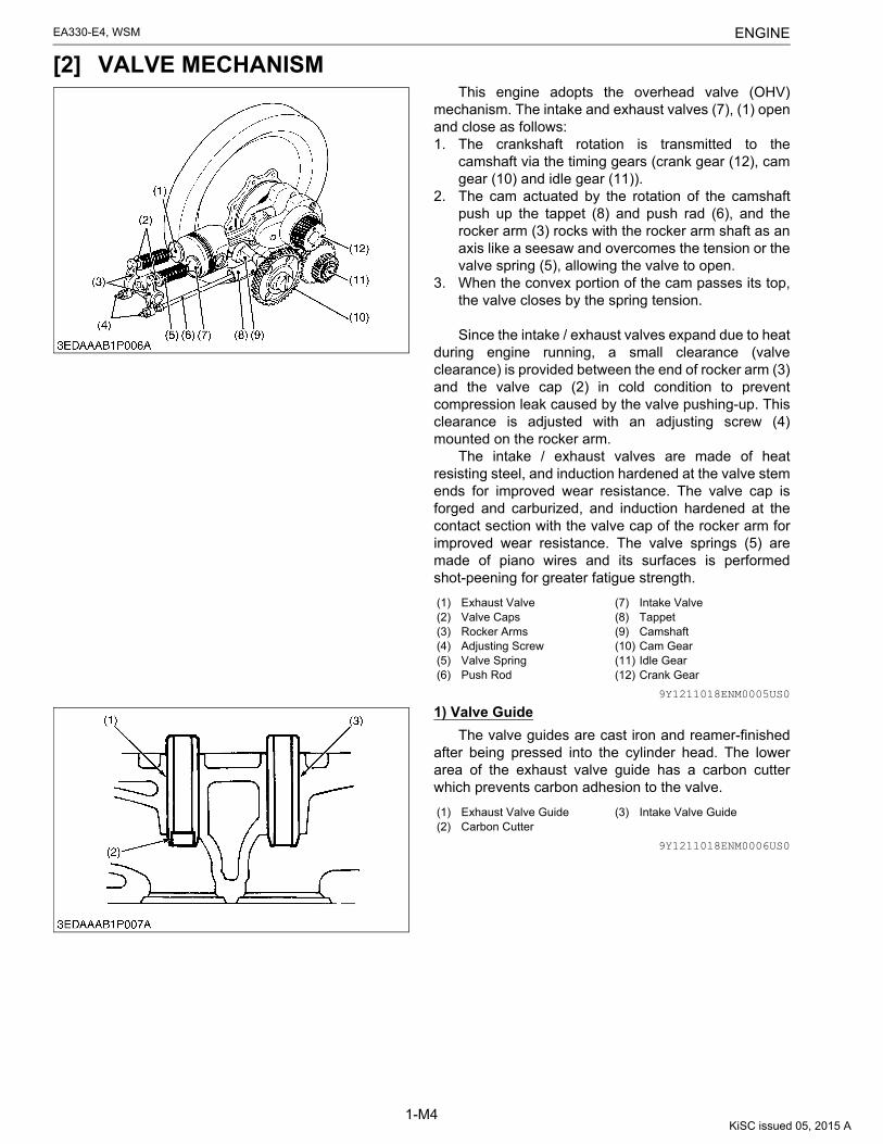
[2] VALVE MECHANISMThis engine adopts the overhead valve (OHV)
mechanism. The intake and exhaust valves (7), (1) openand close as follows:1. The crankshaft rotation is transmitted to the
camshaft via the timing gears (crank gear (12), camgear (10) and idle gear (11)).
2. The cam actuated by the rotation of the camshaftpush up the tappet (8) and push rad (6), and therocker arm (3) rocks with the rocker arm shaft as anaxis like a seesaw and overcomes the tension or thevalve spring (5), allowing the valve to open.
3. When the convex portion of the cam passes its top,the valve closes by the spring tension.
Since the intake / exhaust valves expand due to heatduring engine running, a small clearance (valveclearance) is provided between the end of rocker arm (3)and the valve cap (2) in cold condition to preventcompression leak caused by the valve pushing-up. Thisclearance is adjusted with an adjusting screw (4)mounted on the rocker arm.
The intake / exhaust valves are made of heatresisting steel, and induction hardened at the valve stemends for improved wear resistance. The valve cap isforged and carburized, and induction hardened at thecontact section with the valve cap of the rocker arm forimproved wear resistance. The valve springs (5) aremade of piano wires and its surfaces is performedshot-peening for greater fatigue strength.
9Y1211018ENM0005US0
1) Valve Guide
The valve guides are cast iron and reamer-finishedafter being pressed into the cylinder head. The lowerarea of the exhaust valve guide has a carbon cutterwhich prevents carbon adhesion to the valve.
9Y1211018ENM0006US0
(1) Exhaust Valve(2) Valve Caps(3) Rocker Arms(4) Adjusting Screw(5) Valve Spring(6) Push Rod
(7) Intake Valve(8) Tappet(9) Camshaft(10) Cam Gear(11) Idle Gear(12) Crank Gear
(1) Exhaust Valve Guide(2) Carbon Cutter
(3) Intake Valve Guide
KiSC issued 05, 2015 A

ENGINEEA330-E4, WSM
1-M5
2) Valve Timing
The valve opening and closing timing is extremelyimportant for effectively taking air into the cylinder andsufficiently discharging unnecessary exhaust gas.
An appropriate timing can be obtained by aligningthe alignment line on the crank gear, idle gear and camgear.
9Y1211018ENM0007US0
Intake valve open (I.D.)0.35 rad before T.D.C.(20° before T.D.C.)
Intake valve close (I.C.)0.79 rad after B.D.C.(45° after B.D.C.)
Exhaust valve open (E.O.)0.87 rad before B.D.C.(50° before B.D.C.)
Exhaust valve close (E.C.)0.26 rad after T.D.C.(15° after T.D.C.)
Fuel Injection Timing0.4320 to 0.4581 rad (24.75 to 26.25°) before T.D.C.
(1) Intake(2) Compression(3) Combustion (Power)(4) Exhaust
FI: Fuel InjectionT.D.C.:Top Dead CenterB.D.C.:Bottom Dead Center
(a) 0.35 rad before T.D.C.(20° before T.D.C.)
(b) 0.79 rad after B.D.C.(45° after B.D.C.)
(c) 0.87 rad before B.D.C.(50° before B.D.C.)
(d) 0.26 rad after T.D.C.(15° after T.D.C.)
KiSC issued 05, 2015 A

ENGINEEA330-E4, WSM
1-M6
[3] CYLINDER BLOCK AND CYLINDER LINERThe cylinder block is made of aluminium die-cast.The cylinder block is provided with oil galleries to
lubricate the crankshaft, main bearing case and rockerarm bracket. The cylinder liner (1) made of special castiron having excellent wear resistance, is press fitted intothe cylinder block.
These engines adopt a wet type cylinder liner whichperiphery comes into direct contact with coolant. Toprevent water leakage, O-rings (2) are installed at thelower part of cylinder liner periphery. To prevent gasleakage, the upper part of the liner slightly protrudesfrom the cylinder block. This is because the gasket at thispart is tightened strongly between the cylinder head andthe liner.
NOTE• Similarly as the aluminum alloy gear case, etc.
cylinder blocks that are made of aluminum alloyare prone to scratches and greater thermalexpansion. Therefore, following advises need tobe followed during repair.
• Parts must be tightened when they are cold.• Follow specified tightening torques accurately.• Protect processed surfaces, especially, from
scratches.
9Y1211018ENM0008US0
[4] CRANKSHAFT AND CRANKSHAFT JOURNAL BEARINGThe crankshaft (1) is made of tough special alloy
steel, and the pin and oil seal slinging portions areinduction hardened to increase the hardness for higherwear resistance.
The journal portions are supported by main bearing1 (7) and 2 (5).
The crankshaft is provided with an oil gallery whichfeeds engine oil to the pin portion and lubricate it.
The oil fed from the oil pump travels along the grooveon the oil filler rings (3), passes through the oil gallery inthe crankshaft and lubricates the crank pin part. The fillerring is made of aluminum alloy casting.
The oil seal (2) is provided to prevent oil leakage.
9Y1211018ENM0009US0
(1) Cylinder Liner(2) O-ring
(3) Cylinder Block
(1) Crankshaft(2) Oil Seal(3) Oil Filler Ring(4) Main Bearing Case
(5) Main Bearing 2(6) Crank Pin Bearing(7) Main Bearing 1
KiSC issued 05, 2015 A

ENGINEEA330-E4, WSM
1-M7
[5] PISTON AND PISTON RINGSince the piston is always subjected to high
temperature and high pressure and reciprocates withinthe cylinder, it must be lightweight, tough, heat resistant,wear resistant, and of little thermal expansion. For thisreason, the piston is made of High-silicone (aluminiumalloy).
The piston crown is flat-formed. Grooves are formedaround the piston crown and these aid heat dissipationand prevent scuffing of the piston and cylinder liner.
The piston has three piston rings.The top ring (1) is of a Keystone type to prevent gas
leakage, and it designed for a better initial fit and toprevent abnormal wear and seizure. The ring surface ishard-chromium plated for improved wear resistance.
The second ring (2) is an under-cut type whicheffectively prevents the rise of oil.
The oil ring (3) has chamfered contact faces and anexpander ring, which increase the pressure of the oil ringagainst the cylinder wall.
A portion of the scraped oil is forced inside the pistonas it passes through escape holes in rings and piston.These oil rings are plated with hard chrome to giveincreased wear resistance.
9Y1211018ENM0010US0
[6] CONNECTING ROD AND CONNECTING ROD BEARINGThe connecting rod (2) is made of I-shape forging of
carbon steel so that it can withstand large repetitiveimpacts.
The big end of the connecting rod is of a horizontalsplit type and tightened with special screws. Since theconnecting rod body (2) and cap (4) are I.D. machinedafter matching, matching must not be changed.
The crank pin bearing (3) is a split type, and made ofcopper-lead alloy (called Kelmet) (with a mild steel backmetal). The surface is tin plated to obtain a better initialfit.
The piston pin bushing (1) is made of lead bronze(with a mild steel back metal) which has the mostexcellent shock resistance, load resistance and heatresistance. The surface is tin plated.
9Y1211018ENM0011US0
(1) Top Ring(2) Second Ring
(3) Oil Ring
(1) Piston Pin Bushing(2) Connecting Rod
(3) Crank Pin Bearing(4) Connecting Rod Cap
KiSC issued 05, 2015 A

ENGINEEA330-E4, WSM
1-M8
[7] TIMING GEARThe timing gears consisting of the crank gear (2),
cam gear (1), idle gear (6), (7) and balancer gears (4),(5) serve to correctly control the intake and exhaustvalves opening, closing timing, fuel injection timing andbalance movement, etc.
Respective gears are marked with alignment marksto assure correct relative positioning of gears whenassembling. For these timing gears, helical gears areused. They smoothly convey rotations with less noise.
9Y1211018ENM0012US0
[8] CAMSHAFTThe camshaft is made of carbon steel forging and its
cam and journal faces are induction hardened.The oval-shaped cam improves intake efficiency and
at the same time reduces noise.On the camshaft, the cam gear (3) is installed.The camshaft is provided with an intake and exhaust
cam to actuate the intake and exhaust valves. Inaddition, a groove is machined at the tip of the camshaftto drive the trochoid pump for lubrication.
9Y1211018ENM0013US0
[9] FLYWHEELThe flywheel stores the rotating force in the
combustion stroke as inertial energy, reduces crankshaftrotating speed fluctuation and maintains the smoothrotating conditions.
On the circumference of the flywheel are stampedthe top dead center "T" mark and four lines indicatingevery 0.03 rad (2 °) of crank angle from 0.35 rad (20 °) to0.49 rad (28 °) before mark "T".
On the NB type, ring gears are press-fitted into theperiphery inside the flywheel to allow the engine to bestarted withe a starter.
9Y1211018ENM0014US0
(1) Cam Gear(2) Crank Gear(3) Balancer Gear 2(4) Balancer Gear 3
(5) Balancer Gear 1(6) Idle Gear (45T)(7) Idle Gear (21T)
(1) Camshaft(2) Camshaft Stopper
(3) Cam Gear
(1) Fuel Injection Timing Line(2) Fan Cover Mark
(3) T.D.C. Mark "T"
KiSC issued 05, 2015 A

ENGINEEA330-E4, WSM
1-M9
[10] DYNAMIC BALANCERThe engine has a dynamic balancer (biaxial
balancer) to offset primary force caused by thereciprocating motion of the piston. This significantlyreduces engine vibration and resultant vibrating noises.
9Y1211018ENM0015US0
KiSC issued 05, 2015 A

ENGINEEA330-E4, WSM
1-M10
3. LUBRICATING SYSTEM[1] GENERAL
Lubrication is forced on with a trochoid pump.Lubrication oil is sucked in by the trochoid pump (7) via an oil strainer (8) mounted on the side of the gear case.
The pressure of lubricating oil discharged from the trochoid pump is regulated by a relief valve (6) to 200 to 390 kPa(2.0 to 4.0 kgf/cm2, 29 to 56 psi) (at the rated revolution speed of the engine), and the pressure-regulated oil is thenfed to various portions through the oil gallery in the cylinder block.
Lubricating oil sent to the oil gallery in the crankshaft lubricates the crank pin portion (4).Oil sent to the cylinder head via the oil gallery in the cylinder block lubricates rocker arms (1) via a rocker arm
bracket (2).Other items such as the piston, piston pin bushing (9), cam shaft journal portion, tappet, timing gear and bearings
are lubricated by splash of the crankshaft, etc.An oil signal (5) is provided to enable the judgement whether the oil pressure is 50 kPa (0.5 kgf/cm2, 7 psi) or
more.9Y1211018ENM0016US0
(1) Rocker Arm(2) Rocker Arm Bracket(3) Oil Filler Ring
(4) Crank Pin Portion(5) Oil Signal
(6) Relief Valve(7) Trochoid Pump
(8) Oil Strainer(9) Piston Pin Bushing
KiSC issued 05, 2015 A

ENGINEEA330-E4, WSM
1-M11
[2] OIL PUMPThe oil pump is of trochoid pump type, whose rotors
have trochoid lobes. The inner rotor (3) has 4 lobes andthe outer rotor (4) has 5 lobes, and they are eccentricallyengaged with each other. The inner rotor, which is drivenby the crankshaft through the gears, rotates the outerrotor in the same direction, varying the spaces betweenthe lobes.
While the rotors rotate from (A) to (B), the spaceleading to the inlet port increases, which causes the oilto flow through the inlet port.
When the rotors rotate to (C), the port to which thespace leads is changed from inlet to outlet.
At (D), the space decreases and sucked oil isdischarged from the outlet port.
9Y1211018ENM0017US0
[3] OIL STRAINEREntry of foreign material such as iron chips, dirt, etc.
into the lubricating system may damage the lubricatedparts. To prevent this, an oil strainer is equipped prior tothe oil pump. This strainer has a double wound stainlesssteel net (50 meshes) at the outside, and four magnets(2) are mounted inside.
This stainless steel net (screen (4)) removes smalldirt in the lubricating oil. Further, fine iron chips passingthrough this net are attracted by these magnets toprevent them from entering the lubricating system.
9Y1211018ENM0018US0
[4] RELIEF VALVEThe relief valve consists of ball (4), spring (3), and
plug (1), which holds them, and is built into the lower partof the gear case.
The relief valve (5) is used to adjust the lubricating oilpressure to a proper level (200 to 390 kPa, 2.0 to4.0 kgf/cm2, 29 to 56 psi).
The oil which has passed through the relief valvefalls to the cylinder block.
If this regulated pressure is too low, the delivery oflubricating oil to various portions will become deficientand may cause seizure. Too high oil pressure may causeoil leakage.
9Y1211018ENM0019US0
(1) Inlet(2) Outlet
(3) Inner Rotor(4) Outer Rotor
(1) Plug(2) Magnet(3) Spacer
(4) Stainless Steel Net(5) Spring(6) End Plate
(1) Plug(2) Gasket(3) Spring(4) Ball
(5) Relief Valve(6) Trochoid Pump(7) Oil Strainer
KiSC issued 05, 2015 A
ENGINEEA330-E4, WSM
1-M12
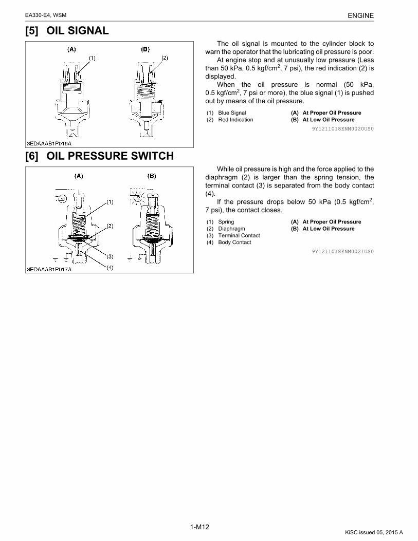
[5] OIL SIGNALThe oil signal is mounted to the cylinder block to
warn the operator that the lubricating oil pressure is poor.At engine stop and at unusually low pressure (Less
than 50 kPa, 0.5 kgf/cm2, 7 psi), the red indication (2) isdisplayed.
When the oil pressure is normal (50 kPa,0.5 kgf/cm2, 7 psi or more), the blue signal (1) is pushedout by means of the oil pressure.
9Y1211018ENM0020US0
[6] OIL PRESSURE SWITCHWhile oil pressure is high and the force applied to the
diaphragm (2) is larger than the spring tension, theterminal contact (3) is separated from the body contact(4).
If the pressure drops below 50 kPa (0.5 kgf/cm2,7 psi), the contact closes.
9Y1211018ENM0021US0
(1) Blue Signal(2) Red Indication
(A) At Proper Oil Pressure(B) At Low Oil Pressure
(1) Spring(2) Diaphragm(3) Terminal Contact(4) Body Contact
(A) At Proper Oil Pressure(B) At Low Oil Pressure
KiSC issued 05, 2015 A

ENGINEEA330-E4, WSM
1-M13
4. COOLING SYSTEM[1] GENERAL
This engine employ a pressurized radiator naturalconvection cooling system.
Cooling by the radiator (1) and radiator fan (2)increases in specific gravity. And it absorbs combustionheat of the cylinder liner (5) and cylinder head (3) andfriction heat generated from moving parts to cool them.
Then, coolant moves upward, as the water absorbsheat and decreases in specific gravity.
The heated water is cooled again by the radiator.Thus, the coolant circulates naturally to cool the engine.
9Y1211018ENM0022US0
[2] RADIATORThe radiator adopted is of a plate fin type which is
durable and resistant to pressure, and has good heattransfer proper ties. As it passes through the radiatorcore, coolant is cooled by air from outside, and is againcirculated to the engine body.
The radiator core is composed of a tube (1), throughwhich water flow, and cooling fins (2). Both of thecomponents are formed of thin copper plate, etc. whichgives good heat transfer. Cooling air passing betweenthe fins helps coolant in the tube to give off heat.
9Y1211018ENM0023US0
(1) Radiator(2) Radiator Fan(3) Cylinder Head
(4) Cylinder Block(5) Cylinder Liner
(1) Tube (2) Cooling Fin(Waved Plate Fin)
KiSC issued 05, 2015 A

ENGINEEA330-E4, WSM
1-M14
[3] RADIATOR CAPRadiator Cap Function
When Radiator Pressure is HighWhen temperature increases inside the radiator,
there is expansion of water followed by conversion ofwater to steam as the temperature continues toincrease.
The pressure valve is designed to prevent internalpressure rising above specified opening pressure(110 kPa, 1.1 kgf/cm2, 16 psi) in order to protect theradiator, therefore, the pressure valve opens allowingsteam to escape, as shown in the figure.
An additional function of the radiator cap is toprevent foam forming inside the engine and to restrict theloss of coolant resulting from temperature increase. When Radiator Pressure is Negative
When the temperature of the coolant decreases,internal pressure becomes negative as a result of watercontraction. In this situation, the vacuum valve opensallowing the entry of air and a return to atmosphericpressure, thereby preventing distortion of the radiator.
9Y1211018ENM0024US0
(1) Pressure Valve(2) Vacuum Valve
[A] At High Pressure[B] At Negative Pressure
KiSC issued 05, 2015 A

ENGINEEA330-E4, WSM
1-M15
5. INTAKE / EXHAUST SYSTEM[1] GENERAL
The intake / exhaust system consists of an intakesystem to supply clean air into the cylinder and anexhaust system to reduce exhaust noise.
The intake system consists of an air cleaner (3) andan inlet pipe (5). The air cleaner prevents dust and dirt inthe air (4), or raindrops from entering into the cylinderand the inlet pipe directs clean, filtered air into thecylinder. The exhaust system consists of a muffler flange(6) that directs exhaust gas (1) from the cylindercollectively into the muffler (2), and muffler to reduceexhaust noise.
9Y1211018ENM0025US0
[2] AIR CLEANERThe air cleaner is a dry type. The air enters it from the
periphery of the element (1), and the air is turned into acyclone swirl by the impeller (2) to separate coarse dustparticles centrifugally from the air. As the air passes theelement, remaining dust is removed from the air, and theclean air is sucked into the cylinder from the center.
9Y1211018ENM0026US0
[3] MUFFLERThe muffler consists of the perforated inner tube (2)
and outer tube (3), glass wool (1), main body (4), etc.The inner and outer tube baffle plates (5) effectivelydampen exhaust noises. The glass wool placed betweenthe outer tube and main body, absorb higher frequencyof exhaust noises.
9Y1211018ENM0027US0
(1) Exhaust Gas(2) Muffler(3) Air Cleaner
(4) Intake Air(5) Inlet Pipe(6) Muffler Flange
(1) Element(2) Impeller
(3) Dust Guide
(1) Glass Wool(2) Inner Tube(3) Outer Tube
(4) Main Body(5) Baffle Plate
KiSC issued 05, 2015 A

ENGINEEA330-E4, WSM
1-M16
6. FUEL SYSTEM[1] GENERAL
Fuel from the fuel tank (10) passes through the fuel filter (8), and then enters the injection pump (4) after impuritiessuch as dirt, water, etc. are removed.
The fuel pressurized by the injection pump to the opening pressure (13.73 to 14.70 MPa, 140.0 to 150.0 kgf/cm2,1992 to 2133 psi), of the injection nozzle (2) is injected into the combustion chamber.
Part of the fuel fed to the injection nozzle (2) lubricates the moving parts of the plunger inside the nozzle, thenreturns to the fuel tank through the fuel overflow pipe (1) from the upper part of the nozzle holder.
9Y1211018ENM0028US0
(1) Fuel Overflow Pipe(2) Injection Nozzle(3) Injection Pipe
(4) Injection Pump(5) Air Vent Pipe 1(6) Air Vent Pipe 2
(7) Fuel Pipe 2(8) Fuel Filter
(9) Fuel Pipe 1(10) Fuel Tank
KiSC issued 05, 2015 A

ENGINEEA330-E4, WSM
1-M17
[2] INJECTION PUMPA Bosch M type mini pump is used for the injection
pump. It is small, lightweight and easy to handle.The plunger (4) with a left-hand lead reciprocates via
the tappet roller (3) by means of the camshaft fuel cam,causing the fuel to be delivered into the injection nozzle.
The fuel in the fuel chamber is drawn into thedelivery chamber when the plunger lowers. When theplunger rises, delivery valve (5) is pushed open to forceinto the injection nozzle.
The control rack (2) is actuated by the governor, andthe control rack movement is transmitted to the controlsleeve (1). As a result, the plunger rotates to vary theamount of fuel fed into the injection nozzle.
When the speed control lever is set to the stopposition, the fuel is not pressurized, and is not injectedsince the feed hole meets with the control groove.
9Y1211018ENM0029US0
Fuel Pressure-feed Stroke to Injection Nozzle
1. Fuel SuctionThe fuel fed into fuel chamber (2) by the action of the
fuel feed pump when plunger (1) is down is drawn intodelivery chamber (4) after passing through feed hole (3).2. Fuel Pressure-feeding Commencement
When plunger (1) rises, the surface of the plungerhead blocks feed hole (3) and the pressure insidedelivery chamber (4) increases thereby raising deliveryvalve (5) and fuel commences to be pressure-feed intothe nozzle.3. During Fuel Pressure-feeding
The plunger continues to rise and pressure-feedingof fuel continues.4. Conclusion of Fuel Pressure-feeding
The plunger continues to rise even further andcontrol groove (6) on the outer periphery of the plungerreaches the feed hole, fuel then passes from deliverychamber (4) through the control groove and returns tofuel chamber (2) after passing once again through feedhole (3).
9Y1211018ENM0030US0
(1) Control Sleeve(2) Control Rack(3) Tappet Roller(4) Plunger
(5) Delivery Valve(6) Delivery Valve Holder(7) Dumping Valve
(1) Plunger(2) Fuel Chamber(3) Feed Hole
(4) Delivery Chamber(5) Delivery Valve(6) Control Groove
KiSC issued 05, 2015 A

ENGINEEA330-E4, WSM
1-M18
Regulating Fuel Injection
1. No Fuel Delivery....Engine StoppedWhen the control rack (5) is set at the engine stop
position, the plunger (2) is rotated to a position where thevertical slot (6) in the plunger (2 aligns with the feed hole(4). Since the vertical slot prevents the feed hole frombeing covered, pressure in the delivery chamber (7)cannot build up. Therefore, no fuel can be forced to theinjection nozzle.2. Fuel Injection....Small to Medium
When the plunger rotates in the direction of the arrowby the action of the control rack (as shown in the figure)and after the head-section of plunger (2) closes off feedhole (4), the quantity of fuel in the effective stroke "A"(the section of strode up until control groove (3) reachesthe feed hole) is fed to the nozzle and injected.3. Fuel Injection....Maximum
When the control rack has moved maximumdistance in the direction of the arrow, effective stroke "B"of the plunger is at its maximum, consequently, fuelinjection is also at maximum.
9Y1211018ENM0031US0
1) Pump ElementThe pump element (1) consists of the plunger (3) and
the cylinder (2). Their sliding surfaces aresuper-precision finished to maintain a sufficient injectionpressure at low speeds.
The driving face (8) goes inside the control sleeve,and moves the control rack. As a result, the plunger (3)is turned and increases or decreases the fuel injectionrate accordingly.
As explained earlier, the plunger is provided with acontrol groove (7), a notch (5) for stopping and a speedadvance lead (6). The control groove is a left-hand lead.
9Y1211018ENM0032US0
(1) Control Sleeve(2) Plunger(3) Control Groove(4) Feed Hole(5) Control Rack
(6) Vertical Rack(7) Delivery Chamber
A: Effective Stroke (Small)B: Effective Stroke (Large)
(1) Pump Element(2) Cylinder(3) Plunger(4) Feed Hole
(5) Notch for Stopping(6) Speed Advance Lead(7) Control Groove(8) Driving Face
KiSC issued 05, 2015 A

ENGINEEA330-E4, WSM
1-M19
2) Delivery ValveThe delivery valve consists of the relief valve (1) and
delivery valve seat (2).
9Y1211018ENM0033US0
Delivery Valve Operation
Non-return FunctionTime delay from the beginning of pressure-feeding of
the pump element to the beginning of nozzlefeed-injection becomes large when the delivery chamberof the pump and the injection nozzle are in alignment andthe cut-off of fuel is also delayed. Then, simultaneouslywith the completion of the pressure-feeding of fuel, thedelivery valve descends as a result of the action of thedelivery valve spring thereby forming a cut-off betweenthe delivery chamber and the injection pipe preventingany reverse flow of fuel.Reverse Suction Function (Dripping Prevention)1. When the pressure-feeding of fuel ends, the delivery
valve lowers and relief valve (1) section comes intocontact with the valve seat.
2. Furthermore, the valve descends until seat surface(2) is in contact with delivery valve seat (3) but as theamount of fuel during interval "A" is sucked backfrom inside the injection pipe, pressure within thepipe is reduced giving improved cut-off of fuelinjection by the nozzle, thereby preventingsubsequent dripping of the injectors.
9Y1211018ENM0034US0
Dumping Valve
At Fuel InjectionSince dumping valve is pushed up to press the
spring, fuel is pressure-fed to injection nozzle the sameas without dumping valve.At Suck-Back
At suck-back by delivery valve after fuel injection,fuel returns through dumping valve orifice. Generallysecond injection is apt to occur by reflex pressure due toreaction of sudden pressure drop when changing intosuck-back by delivery valve from high injection pressure.As a result of preventing this second injection perfectlyby dumping valve and dissolving nozzle clogging,durability of injection nozzle is improved.
9Y1211018ENM0035US0
(1) Relief Valve (2) Delivery Valve Seat
(1) Relief Valve(2) Seat Surface(3) Delivery Valve Seat
(a) Non-return Function(b) Reverse Section Function
(Dripping Prevention)
(1) Dumping Valve(2) Delivery Valve(3) Orifice
(a) At Fuel Injection(b) At Suck-BackA: Suck-back Stroke
KiSC issued 05, 2015 A

ENGINEEA330-E4, WSM
1-M20
[3] INJECTION NOZZLESince the nozzle is a throttle type, only a small
amount of fuel is injected at the initial stage of injection,and the amount increases gradually until a full amount isinjected. As a result, combustion starts up moresmoothly with less noise. Fuel pressurized by theinjection pump pushes up needle valve (7), and as aresult, fuel is injected into the combustion chamber.
The injection pressure is adjusted to openingpressure values in the table below.
If the pressure drops and adjustment is necessary, ashim must be inserted between nozzle holder body (1)and adjustment washer (2). Increases of approximately980 kPa (10 kgf/cm2, 140 psi) will occur with shimthicknesses of 0.1 mm (0.004 in.).
As these components are precision-machined likethe nozzle and pump, adequate care must be taken toprevent entry of water or foreign matter.
9Y1211018ENM0036US0
(1) Nozzle Holder Body(2) Adjustment Washer(3) Nozzle Spring(4) Push Rod(5) Retaining Nut
(6) Nozzle Body(7) Needle Valve(8) Combustion Chamber(9) Eye-tube Joint(10) Overflow Pipe
KiSC issued 05, 2015 A

ENGINEEA330-E4, WSM
1-M21
[4] GOVERNOR MECHANISM
The governor maintains the constant engine speed and at the same time controls the output. The centrifugalmechanical governor used in this engine is an all-speed type which controls engine speed at any point between idlingand maximum speed positions. At Starting
When the speed control lever (7) is moved in the direction "A", the governor lever (6) is pulled in the direction "C"by the force the governor spring (1). At this time, the governor weight (4) has no active centrifugal force, since theengine is not rotating. Thus, the control rack (10) moves to the maximum fuel injection position to facilitate starting ofthe engine. At Idling
When the speed control lever (7) is set in the idling position, the governor spring (1) is almost relaxed and theidling spring (9) of small tension alone is at work. This idling spring works in the direction "C" (to increase fuel supply).To the contrary, the governor weight (4) extends by the centrifugal force in the direction of "E" to push the governorshaft (5) and in turn move the governor lever (6) in the direction of "D" (to decrease the fuel supply). The engine willidle in a condition in which the two forces are balanced with each other.
9Y1211018ENM0037US0
(1) Governor Spring(2) Stop Spring(3) Crank Gear(4) Governor Weight(5) Governor Shaft(6) Governor Lever(7) Speed Control Lever(8) Fuel Limiter(9) Idling Spring(10) Control Rack
KiSC issued 05, 2015 A

ENGINEEA330-E4, WSM
1-M22
At Idling to Maximum SpeedsWhen the engine rotates at idling to maximum speeds, engine rotates at a constant speed at the point where the
governor spring tension and the governor weight's centrifugal force are well balanced. If the load is increased, theengine speeds down and the centrifugal force of the governor weight (4) becomes smaller, so that the control rack(10) is moved in the direction C in which fuel is increased to restore the original speed. In this way, the engine speedis automatically controlled for a constant revolution. At Maximum Engine Speed
When the speed control lever (7) is moved in the direction "A", the governor weight (4) is at the maximumcentrifugal force, with the governor lever (6) contacting the fuel limiter (8). As the load becomes large, the speed isreduced, decreasing the governor lever pushes the fuel limiter (the limiter contains a spring) and moves in thedirection "C". Thus, the control rack (10) is placed at the maximum fuel injection position, producing the maximumengine output power. At Engine Stop
When the speed control lever (7) is moved fully in the direction "B" to the stop position, arm pushes the governorlever pin to move the governor lever (6) in direction "D", thus the control rack (10) is set to the stop position (No fuelinjection) and the engine stops.
9Y1211018ENM0038US0
Fuel Limiter Apparatus Construction
At starting and maximum power point, the governorlever (2) of the fuel limiter pushes the pin (3), whichtouches the lock screw (4) and stops. As a result, thecontrol rack (1) moves to the position at which point thelargest amount of fuel is injected.
9Y1211018ENM0039US0
(1) Governor Spring(2) Stop Spring(3) Crank Gear(4) Governor Weight(5) Governor Shaft(6) Governor Lever(7) Speed Control Lever(8) Fuel Limiter(9) Idling Spring(10) Control Rack
(1) Control Rack(2) Governor Lever
(3) Pin(4) Lock Screw
KiSC issued 05, 2015 A

ENGINEEA330-E4, WSM
1-M23
[5] FUEL FILTEREach moving part of the injection pump and nozzle is
extremely precision machined, and clearances of theirsliding parts are extremely small. Fuel itself serves aslubricating oil. For this reason, it is extremely importantto completely remove water and dirt contained in fuel.
This fuel filter, which uses very fine filter paper,serves to separate and filter dirt in fuel and wateraccumulated in the tank.
After passing through the filter element (6) fromoutside to the center of the filter, the fuel flows to theinjection pump from the fuel outlet port (1).
When the filter element (6) is replaced, or the pipe isremoved, or air enters together with fuel, air isautomatically bled from the air vent port (2), (3).
9Y1211018ENM0040US0
(1) Fuel Outlet Port(2) Air Vent Port(3) Air Vent Port
(4) Fuel Inlet(5) Fuel Valve(6) Fuel Element
KiSC issued 05, 2015 A

ENGINEEA330-E4, WSM
1-M24
7. ELECTRICAL SYSTEM[1] GENERALEA330-E4-NB1
Color of Wiring
9Y1211018ENM0041US0
(1) Battery (option)(2) Starter(3) Oil Switch (option)(4) Glow Plug
(5) Fan Dynamo(6) Switch Box(7) Starter Switch
(8) Oil Lamp(9) Glow Lamp(10) Regulator
(11) Glow Lamp Timer(12) Fuse
Bl...................................Black Ye ................................ Yellow Re ................................Red
Blu.................................Blue Bl / Wh ......................... Black / White Bl / Re ..........................Black / Red
Re / Wh ........................Red / White Gr ................................ Green
KiSC issued 05, 2015 A

ENGINEEA330-E4, WSM
1-M25
The electrical system of this engine comes equippedwith the starter, glow plug, fan dynamo and switch box asstandard.
The fan dynamo is a single-phase alternating currentgenerator built in the radiator fan. The rectifier rectifiesthe single-phase alternating current. When the rectifiedcurrent voltage is higher than the battery voltage, thebattery is charged. When the battery is charged and itsvoltage exceeds approximately 14 V, the zener diode ofthe current limiter conduct, causing the thyristor toconduct. Thus, current generated at the dynamo isgrounded directly through the thyristor, preventingovercharge.
NOTE• The thick line indicates a circuit normally live
with 12 V.9Y1211018ENM0042US0
[2] FAN DYNAMOThe fan dynamo generates a single-phase
alternating current as the permanent magnet (2) which isan integral part of the fan (1) rotates outside the dynamocoil (3) which is fixed.Power Generating Performance
9Y1211018ENM0043US0
Recommendation battery changing capability
28 to 32 Ah
EA330-E4-NB1EA330-E4-NB1-APU-1
13V 1.6 to 2.6 A(Fan speed: 6950 min-1 (rpm))
(1) Fan(2) Permanent Magnet
(3) Fan Dynamo
KiSC issued 05, 2015 A

ENGINEEA330-E4, WSM
1-M26
[3] STARTER
9Y1211018ENM0044US0
(1) Drive End Frame(2) Drive Lever(3) Cover(4) Magnet Switch(5) Plug
(6) Bushing(7) Collar(8) Snap Pin(9) Overrunning Clutch(10) Armature
(11) Brush Spring(12) Bushing(13) Gasket(14) Brake Spring(15) Brake Shoe
(16) End Frame Cap(17) Yoke(18) Brush Holder(19) End Frame
KiSC issued 05, 2015 A

ENGINEEA330-E4, WSM
1-M27
1) Starting MotorThe starting motor converts the electrical energy into
rotary mechanical energy to crank the engine, and iscomposed of an armature, commutator, field coil,brushes and others.
9Y1211018ENM0045US0
(1) Armature Shaft(2) Stopper(3) Coil(4) Slot Insulator(5) Armature Core(6) Hemp String(7) Commutator(8) Rubber Bushing(9) Cotton Tape(10) Flat Wire(11) Yoke(12) Brush(13) Pole Core(14) Armature
[A] Armature Construction[B] Field Coil and Brush
Constructions[C] Motor Circuit
KiSC issued 05, 2015 A

ENGINEEA330-E4, WSM
1-M28
2) Overrunning ClutchThe overrunning clutch prevents the armature from
being driven by the rotational force of the engine whenthe pinion and the engine flywheel ring gear are in mesh.1. When power is transmitted, the rotational force of the
outer clutch gear (1) drives the pinion gear (6)through the roller (2).
2. Even when the pinion gear is driven by the engineflywheel ring gear and its speed exceeds that of theouter clutch gear, the rotation force of the ring gearis not transmitted to the outer clutch gear.
9Y1211018ENM0046US0
3) Armature BrakeThe armature brake stops armature rotation
immediately after the starter switch is turned off.
9Y1211018ENM0047US0
(1) Outer Clutch Gear(2) Roller(3) Roller Spring(4) Inner Spline Tube(5) Pinion Shaft, Solid with
Pinion Gear(6) Pinion Gear(7) Locked Position(8) Clutch Cover
[A] Overrunning Clutch Operation
[B] Overrunning Clutch Construction
(a) When Power is Transmitted
(b) Idling Rotation with Shaft Speed Exceeding That of Outer Clutch
(1) Overrunning Clutch(2) Brake Spring(3) Armature(4) Yoke(5) Brush Spring(6) Brush Holder
(7) Brush(8) Washer(9) Brake Spring(10) End Frame(11) Field Coil
KiSC issued 05, 2015 A

ENGINEEA330-E4, WSM
1-M29
4) Magnet SwitchThe magnet switch serves as a relay to drive the
armature. It consists of a pull-in coil, a holding coil and aplunger. It works as follows.1. When the starter switch is set to START position, the
armature is rotated at a small amperage as thepull-in coil (9) and the holding coil (7) attract theplunger (6) to the left.
2. When the main circuit from the contact plate (11) toarmature is closed by the plunger (6), the armaturestarts rotating at a strong torque.At the same time, a current stops flowing into thepull-in coil and the plunger is kept attracted by theholding coil alone.
3. When the starter switch is released after starting theengine, the flow of a current to the holding coil alsostops. Thus, the armature stops rotating.
9Y1211018ENM0048US0
(1) Joint(2) Switch Housing(3) Return Spring(4) Magnetic Cover(5) Switch Cover(6) Plunger(7) Holding Coil(8) Plunger Shaft(9) Pull-in Coil(10) Spring(11) Contact Plate
[A] Magnet Switch Construction
[B] Pull-in and Holding Coil
KiSC issued 05, 2015 A

ENGINEEA330-E4, WSM
1-M30
5) Operation of Starter When Starter Switch is Turned to START
PositionCurrent from the battery flows through the pull-in coil
and holding coil, producing the magnetism in thewindings to pull the plunger in.
At this time, the drive lever moves the pinion toengage with the ring gear.
When Contact Plate is ClosedLarge current flows through the motor section to
operate the motor.At this time, the pinion is moved forward by the screw
for more contact.Since the pull-in coil ends are short-circuit by the
contact plate, the plunger is held only by the magnetismof the holding coil.
When Starter Switch is ReleasedCurrent flows instantaneously through the pull-in coil
the opposite direction as shown in figure. Therefore, themagnetic field is collapsed immediately.
As a result, the plunger is returned by the returnspring. Simultaneously, the pinion is disengaged fromthe ring gear, the contact plate is disconnected, and thestarter is immediately stopped by the armature brake.
9Y1211018ENM0049US0
(1) Drive Lever(2) Contact Plate(3) Commutator(4) Screw(5) Armature(6) Pole Core(7) Return Spring(8) Battery(9) Ground(10) Pinion(11) Ring Gear(12) Spline Tube
A: Operated by LeverPC: Pull-in CoilHC: Holding CoilS: Switch
KiSC issued 05, 2015 A

ENGINEEA330-E4, WSM
1-M31
[4] GLOW PLUGThe glow plug is used for pre-combustion chamber
of the cylinder head to make starting easier. The glowplug is quick-heating type, which makes starting easierwith short pre-hearing time
9Y1211018ENM0050US0
KiSC issued 05, 2015 A

CONTENTS
1. TROUBLESHOOTING.................................................................................................................1-S12. SERVICING SPECIFICATIONS ..................................................................................................1-S53. TIGHTENING TORQUES..........................................................................................................1-S11
[1] TIGHTENING TORQUES FOR SPECIAL USE SCREWS, BOLTS AND NUTS.................1-S11[2] TIGHTENING TORQUES FOR GENERAL USE SCREWS, BOLTS AND NUTS...............1-S12
4. CHECKING, DISASSEMBLING AND SERVICING ...................................................................1-S13[1] CHECKING AND ADJUSTING............................................................................................1-S13
(1) Engine Body ..................................................................................................................1-S13(2) Lubricating System........................................................................................................1-S16(3) Cooling System .............................................................................................................1-S17(4) Fuel System...................................................................................................................1-S19(5) Electrical System...........................................................................................................1-S22
[2] DISASSEMBLING AND ASSEMBLING ..............................................................................1-S23(1) Draining Coolant and Oil ...............................................................................................1-S23(2) External Components ....................................................................................................1-S23(3) Cylinder Head................................................................................................................1-S26(4) Gear Case .....................................................................................................................1-S30(5) Piston and Connecting Rod...........................................................................................1-S35(6) Flywheel and Crankshaft ...............................................................................................1-S38(7) Starter............................................................................................................................1-S42
[3] SERVICING.........................................................................................................................1-S44(1) Cylinder Head and Valves .............................................................................................1-S44(2) Piston and Connecting Rod...........................................................................................1-S50(3) Crankshaft .....................................................................................................................1-S53(4) Timing Gear and Camshaft ...........................................................................................1-S55(5) Cylinder Liner ................................................................................................................1-S59(6) Oil Pump........................................................................................................................1-S60(7) Starter............................................................................................................................1-S61
SERVICING
KiSC issued 05, 2015 A
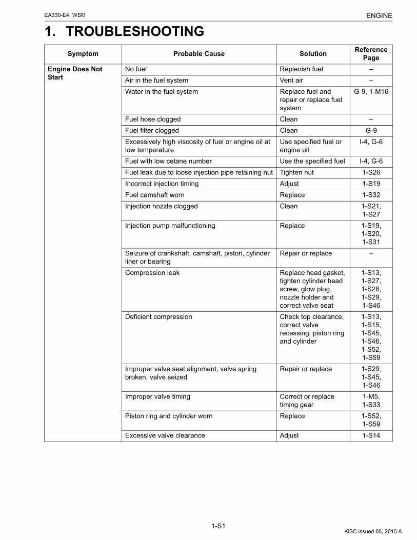
ENGINEEA330-E4, WSM
1-S1
1. TROUBLESHOOTING
Symptom Probable Cause SolutionReference
Page
Engine Does Not Start
No fuel Replenish fuel –
Air in the fuel system Vent air –
Water in the fuel system Replace fuel and repair or replace fuel system
G-9, 1-M16
Fuel hose clogged Clean –
Fuel filter clogged Clean G-9
Excessively high viscosity of fuel or engine oil at low temperature
Use specified fuel or engine oil
I-4, G-6
Fuel with low cetane number Use the specified fuel I-4, G-6
Fuel leak due to loose injection pipe retaining nut Tighten nut 1-S26
Incorrect injection timing Adjust 1-S19
Fuel camshaft worn Replace 1-S32
Injection nozzle clogged Clean 1-S21, 1-S27
Injection pump malfunctioning Replace 1-S19, 1-S20, 1-S31
Seizure of crankshaft, camshaft, piston, cylinder liner or bearing
Repair or replace –
Compression leak Replace head gasket, tighten cylinder head screw, glow plug, nozzle holder and correct valve seat
1-S13, 1-S27, 1-S28, 1-S29, 1-S46
Deficient compression Check top clearance, correct valve recessing, piston ring and cylinder
1-S13, 1-S15, 1-S45, 1-S46, 1-S52, 1-S59
Improper valve seat alignment, valve spring broken, valve seized
Repair or replace 1-S29, 1-S45, 1-S46
Improper valve timing Correct or replace timing gear
1-M5, 1-S33
Piston ring and cylinder worn Replace 1-S52, 1-S59
Excessive valve clearance Adjust 1-S14
KiSC issued 05, 2015 A

ENGINEEA330-E4, WSM
1-S2
Starter Does Not Run Battery discharged Charge –
Starter malfunctioning Repair or replace 1-S22, 1-S42, 1-S61, 1-S62, 1-S63, 1-S64
Starter switches malfunctioning Replace –
Wiring disconnected Connect 1-M24
Engine Revolution Is Not Smooth
Fuel filter clogged or dirt Clean or replace G-9
Air cleaner clogged Clean or replace G-8
Fuel leak due to loose injection pipe retaining nut Tighten nut 1-S26
Injection pump malfunctioning Replace 1-S19, 1-S31
Incorrect nozzle opening pressure Adjust 1-S21, 1-S27
Injection nozzle stuck or clogged Repair or replace 1-S21, 1-S27
Fuel over flow hose clogged Clean –
Governor malfunctioning Repair 1-S33
Either White or Blue Exhaust Gas Is Observed
Excessive engine oil Reduce to the specified level
G-7
Piston ring and liner worn or stuck Repair or replace 1-S52, 1-S59
Incorrect injection timing Adjust 1-S19
Deficient compression Check top clearance, correct valve recessing, piston ring and cylinder
1-S13, 1-S15, 1-S45, 1-S46, 1-S52, 1-S59
Either Black or Dark Gray Exhaust Gas Is Observed
Overload Lessen the load –
Low grade fuel used Use the specified fuel I-4, G-6
Fuel filter clogged Replace G-9
Air cleaner clogged Clean or replace G-8
Deficient Output Incorrect injection timing Adjust 1-S19
Engine's moving parts seem to be seizing Repair or replace –
Deficient nozzle injection Repair or replace the nozzle
1-S21, 1-S27
Compression leak Replace head gasket, tighten cylinder head screw, glow plug, nozzle holder and correct valve seat
1-S13, 1-S27, 1-S28, 1-S29, 1-S46
Symptom Probable Cause SolutionReference
Page
KiSC issued 05, 2015 A

ENGINEEA330-E4, WSM
1-S3
Excessive Lubricant Oil Consumption
Piston ring's gap facing the same direction Shift ring gap direction
1-S36
Oil ring worn or stuck Replace 1-S37, 1-S52
Piston ring groove worn Replace the piston 1-S52
Valve stem and valve guide worn Replace 1-S46, 1-S47
Crank pin bearing worn Replace 1-S35, 1-S53
Oil leak Repair –
Fuel Mixed into Lubricant Oil
Injection pump's plunger worn Replace injection pump assembly
1-S19, 1-S31
Injection pump broken Replace 1-S19, 1-S31
Water Mixed into Lubricant Oil
Head gasket defective Replace 1-S28
Cylinder block or cylinder head flawed Replace 1-S44
Low Oil Pressure(Engine oil pressure)
Engine oil insufficient Replenish G-7
Oil strainer clogged Clean G-8
Relief valve stuck with dirt Clean 1-M10, 1-M11
Relief valve spring weaken or broken Replace 1-M10, 1-M11
Excessive oil clearance of oil filler ring Replace 1-S38, 1-S54
Excessive oil clearance of crank pin bearing Replace 1-S35, 1-S53
Excessive oil clearance of rocker arm bushing Replace 1-S28, 1-S48
Oil passage clogged Clean 1-M10
Different type of oil Use the specified type of oil
I-4, G-6
Oil pump defective Repair or replace 1-S31, 1-S60
High Oil Pressure(Engine oil pressure)
Different types of oil Use specified type of oil
I-4, G-6
Relief valve defective Replace 1-M10, 1-M11
Symptom Probable Cause SolutionReference
Page
KiSC issued 05, 2015 A

ENGINEEA330-E4, WSM
1-S4
9Y1211018ENS0001US0
Engine Overheated Engine oil insufficient Replenish G-7
Fan belt broken or tensioned improperly Replace or adjust 1-S17
Coolant insufficient Replenish G-7
Radiator net and radiator fin clogged with dust Clean G-7
Inside of radiator corroded Clean or replace 1-S25
Coolant flow route corroded Clean or replace 1-M13
Radiator cap defective Replace 1-S18
Overload running Loosen the load –
Head gasket defective Replace 1-S28
Incorrect injection timing Adjust 1-S19
Unsuitable fuel used Use specified fuel I-4, G-6
Battery Quickly Discharge (NB type)
Battery fluid insufficient Replenish distilled water and charge
–
Fan belt slips Adjust belt tension or replace
1-S17
Wiring defective Correct 1-M24
Fan dynamo defective Replace 1-M25, 1-S22, 1-S24
Battery defective Replace –
Glow Plug Indicator Heats too Slowly or Does Not Heat (EA330-NB1)
Glow plug defective Replace 1-M24, 1-S22, 1-S24
Wiring improper Check and correctly connect
1-M24
Glow plug indicator defective Replace –
Battery discharged or defective Charge or replace –
Glow Plug Indicator Heats too Quickly
Glow plug or glow plug indicator short-circuited or wiring between them short-circuit
Repair or replace 1-M24
Symptom Probable Cause SolutionReference
Page
KiSC issued 05, 2015 A

ENGINEEA330-E4, WSM
1-S5
2. SERVICING SPECIFICATIONSENGINE BODY
Item Factory Specification Allowable Limit
Cylinder head surface Flatness – 0.05 mm / 100 mm0.002 in. / 3.94 in.
Top Clearance 0.60 to 0.80 mm0.024 to 0.031 in.
–
Compression Pressure 3.48 MPa35.5 kgf/cm2
505 psi
2.60 MPa26.5 kgf/cm2
377 psi
Decompression Device 0.940 to 1.31 mm0.0370 to 0.0515 in.
–
Valve Clearance (Cold) 0.16 to 0.20 mm0.0063 to 0.0078 in.
–
Valve Face Angle 0.786 to 0.794 rad45.0 to 45.5 °
–
Valve Seat Angle 0.785 rad45.0 °
–
Valve Seat Width 2.1 mm0.083 in.
–
Valve Recessing 0.80 to 0.90 mm0.032 to 0.035 in.
1.5 mm0.059 in.
Valve Stem and Valve Guide
• Valve Stem
• Valve Guide Bore
Oil Clearance
O.D.
I.D.
0.035 to 0.065 mm0.0014 to 0.0025 in.
6.960 to 6.975 mm0.2741 to 0.2746 in.
7.010 to 7.025 mm0.2760 to 0.2765 in.
0.1 mm0.004 in.
–
–
Intake Valve Open
Close
0.35 rad20 ° before T.D.C.
0.79 rad45 ° after B.D.C.
–
–
Exhaust Valve Open
Close
0.87 rad50 ° before B.D.C.
0.26 rad15 ° after T.D.C.
–
–
Valve Spring Free Length 34.5 mm1.36 in.
33.8 mm1.33 in.
Valve Spring Setting Load / Setting Length 59 N / 31 mm6.0 kgf / 31 mm13 lbf / 1.2 in.
49 N / 31 mm5.0 kgf / 31 mm11 lbf / 1.2 in.
Valve Spring Tilt – 1.2 mm0.047 in.
KiSC issued 05, 2015 A

ENGINEEA330-E4, WSM
1-S6
Rocker Arm shaft and Rocker Arm I.D.
• Rocker Arm Shaft
• Rocker Arm
Oil Clearance
O.D.
I.D.
0.016 to 0.045 mm0.00063 to 0.0017
10.973 to 10.984 mm0.43201 to 0.43244 in.
11.000 to 11.018 mm0.43307 to 0.43377 in.
0.15 mm0.0059 in.
–
–
Tappet and Guide
• Tappet
• Tappet Guide Bore
Oil Clearance
O.D.
I.D.
0.020 to 0.062 mm0.00079 to 0.0024 in.
19.959 to 19.980 mm0.78579 to 0.78661 in.
20.000 to 20.021 mm0.78741 to 0.78822 in.
0.15 mm0.0059 in.
–
–
Push Rod Alignment – 0.125 mm0.00492 in.
Piston Skirt O.D. 76.925 to 76.945 mm3.0286 to 3.0293 in.
Liner I.D.0.25 mm0.0098 in.
Piston Pin Bore I.D. 20.000 to 20.013 mm0.78741 to 0.78791 in.
20.04 mm0.7890 in.
Clearance between Ring Groove and Ring Top Ring
Second Ring
Oil Ring
–
0.0850 to 0.112 mm0.00335 to 0.00440 in.
0.020 to 0.055 mm0.00079 to 0.0021 in.
–
0.2 mm0.008 in.
0.15 mm0.0059 in.
Ring Gap Top Ring
Second Ring
Oil Ring
0.30 to 0.45 mm0.012 to 0.017 in.
0.30 to 0.45 mm0.012 to 0.017 in.
0.25 to 0.40 mm0.0099 to 0.015 in.
1.2 mm0.047 in.
1.2 mm0.047 in.
1.2 mm0.047 in.
Connecting Rod Alignment – 0.05 mm / 100 mm0.002 in. / 3.94 in.
Piston Pin and Bushing
• Piston Pin
• Piston Pin Bushing
Oil Clearance
O.D.
I.D.
0.014 to 0.038 mm0.00056 to 0.0014 in.
20.002 to 20.011 mm0.78748 to 0.78783 in.
20.025 to 20.040 mm0.78839 to 0.78897 in.
0.15 mm0.0059 in.
–
–
Crankshaft Alignment – 0.04 mm0.002 in.
Item Factory Specification Allowable Limit
KiSC issued 05, 2015 A

ENGINEEA330-E4, WSM
1-S7
Crankshaft and Oil Filler Ring
• Crankshaft
• Oil Filler Ring
Oil Clearance
O.D.
I.D.
0.025 to 0.066 mm0.00099 to 0.0025 in.
34.959 to 34.975 mm1.3764 to 1.3769 in.
35.000 to 35.025 mm1.3780 to 1.3789 in.
0.2 mm0.008 in.
–
–
Crank Pin and Bearing
• Crank Pin
• Crank Pin Bearing
Oil Clearance
O.D.
I.D.
0.019 to 0.077 mm0.00075 to 0.0030 in.
36.959 to 36.975 mm1.4551 to 1.4557 in.
36.994 to 37.036 mm1.4565 to 1.4581 in.
0.2 mm0.008 in.
–
–
Crankshaft Side Clearance 0.050 to 0.46 mm0.0020 to 0.018 in.
0.56 mm0.022 in.
Timing Gear Backlash Barancer Gear 1 × Barancer Gear 2
Other Gears
0.0490 to 0.135 mm0.00193 to 0.00531 in.
0.0430 to 0.130 mm0.00170 to 0.00511 in.
0.3 mm0.01 in.
–
Idle Gear Side Clearance 0.20 to 0.51 mm0.0079 to 0.020 in.
0.9 mm0.04 in.
Idle Gear Shaft and Idle Gear Bushing
• Idle Gear Shaft
• Idle Gear Bushing
Oil Clearance
O.D.
I.D.
0.016 to 0.045 mm0.00063 to 0.0017 in.
17.973 to 17.984 mm0.70760 to 0.70803 in.
18.000 to 18.018 mm0.70867 to 0.70937 in.
0.1 mm0.004 in.
–
–
Camshaft Alignment – 0.08 mm0.003 in.
Cam Height (IN, EX) 27.0 mm1.06 in.
26.5 mm1.04 in.
Camshaft (Flywheel Side)
• Camshaft Journal
• Camshaft Bore
Oil Clearance
O.D.
I.D.
0.020 to 0.054 mm0.00079 to 0.0021 in.
21.967 to 21.980 mm0.86485 to 0.86535 in.
22.000 to 22.021 mm0.86615 to 0.86696 in.
0.25 mm0.0098 in.
–
–
Camshaft (Gear Side)
• Camshaft Journal
• Camshaft Bore
Oil Clearance
O.D.
I.D.
0.025 to 0.066 mm0.00099 to 0.0025 in.
32.959 to 32.975 mm1.2976 to 1.2982 in.
33.000 to 33.025 mm1.2993 to 1.3001 in.
0.1 mm0.004 in.
–
–
Item Factory Specification Allowable Limit
KiSC issued 05, 2015 A

ENGINEEA330-E4, WSM
1-S8
Cam Gear Side Clearance 0.0700 to 0.220 mm0.00276 to 0.00866 in.
0.3 mm0.01 in.
Cylinder Liner I.D. 75.000 to 75.019 mm2.9528 to 2.9535 in.
+0.25 mm+0.0098 in.
Projection of Cylinder Liner 0.030 to 0.13 mm0.0012 to 0.0051 in.
–
Item Factory Specification Allowable Limit
KiSC issued 05, 2015 A

ENGINEEA330-E4, WSM
1-S9
LUBRICATING SYSTEM
COOLING SYSTEM
FUEL SYSTEM
Item Factory Specification Allowable Limit
Engine Oil Pressure At Idle Speed 50 kPa0.5 kgf/cm2
7 psi or more
–
At Rated Speed(Engine Speed)
250 kPa2.5 kgf/cm2
36 psi or more(3000 rpm)
200 kPa2.0 kgf/cm2
28 psi(3000 rpm)
Inner Rotor to Outer Rotor Clearance 0.15 mm or less0.0059 in. or less
0.20 mm0.0079 in.
Outer Rotor to Pump Body Clearance 0.0900 to 0.171 mm0.00355 to 0.00673 in.
0.24 mm0.0094 in.
Inner Rotor to Cover Clearance 0.02 to 0.06 mm0.0008 to 0.002 in.
0.25 mm0.0098 in.
Relief Pressure 200 to 390 kPa2.0 to 4.0 kgf/cm2
29 to 56 psi
–
Item Factory Specification Allowable Limit
Fan Belt Tension 5.0 to 10 mm / 98 N0.20 to 0.39 in.(10 kgf, 22 Ibs)
–
Radiator Water Tightness No leak at190 kPa
1.9 kgf/cm2
27 psi
–
Radiator Cap Air Leakage 10 seconds or more110 → 80 kPa
1.1 → 0.8 kgf/cm2
16 → 10 psi
–
Item Factory Specification Allowable Limit
Injection Timing (Static) 0.4320 to 0.4581 rad(24.75 to 26.25 °)
before T.D.C.
–
Fuel Tightness of Pump Element – 13.73 MPa140.0 kgf/cm2
1991 psi
Fuel Tightness of Delivery Valve 10 seconds13.73 → 12.75 MPa
140.0 → 130.0 kgf/cm2
1991 → 1849 psi
5 seconds13.73 → 12.75 MPa
140.0 → 130.0 kgf/cm2
1991 → 1849 psi
Fuel Injection Pressure 13.73 to 14.70 MPa140.0 to 150.0 kgf/cm2
1992 to 2133 psi
–
Fuel Tightness of Nozzle Valve Seat 12.75 to 13.72 MPa130.0 to 140.0 kgf/cm2
1849 to 1991 psi
–
KiSC issued 05, 2015 A

ENGINEEA330-E4, WSM
1-S10
ELECTRICAL SYSTEM
9Y1211018ENS0002US0
Item Factory Specification Allowable Limit
Power Generation Performance[Fan Dynamo:(EA330-E4-NB1, EA330-E4-NB1-APU-1)]
Fan Speed
Voltage
Current
6900 min-1 (rpm)
Approx. 13 V
1.6 to 2.6 A
–
–
–
Glow Plug Resistance(at cold occasion)
Approx. 0.9 V –
Starter Commutator O.D. 28.0 mm1.10 in.
27.0 mm1.06 in.
Starter Mica Undercut 0.5 to 0.8 mm0.02 to 0.03 in.
0.2 mm0.008 in.
Starter Brush Length 16.0 mm0.630 in.
10.5 mm0.413 in.
KiSC issued 05, 2015 A

ENGINEEA330-E4, WSM
1-S11
3. TIGHTENING TORQUES[1] TIGHTENING TORQUES FOR SPECIAL USE SCREWS, BOLTS
AND NUTSScrew, bolts and nuts must be tightened to the specified torque using a torque wrench.Several bolts and nuts such as ones used on the cylinder head must be tightened in proper sequence and to the
proper torque.
NOTE• For "**" marked screws and nuts on the table, apply engine oil to their threads and seats before
tightening.9Y1211018ENS0003US0
Item Size × Pitch N·m kgf·m lbf·ft
Cylinder head (Stud) M9 × 1.25 25 to 29 2.5 to 3.0 18 to 21
**Cylinder head (Nut) M9 × 1.25 57 to 61 5.8 to 6.3 42 to 45
**Connecting rod screw M7 × 0.75 27 to 30 2.7 to 3.1 20 to 22
**Flywheel nut M20 × 1.5 197 to 215 20.0 to 22.0 145 to 159
Main bearing case mounting screw / nut
M6 × 1.0 9.81 to 11.2 1.00 to 1.15 7.24 to 8.31
Crankcase cover mounting screw M6 × 1.0 7.9 to 9.3 0.80 to 0.95 5.8 to 6.8
Gear case mounting screw M6 × 1.0 9.81 to 11.2 1.00 to 1.15 7.24 to 8.31
Idle gear shaft screw M6 × 1.0 9.81 to 11.2 1.00 to 1.15 7.24 to 8.31
Head cover mounting nut M7 × 1.0 9.8 to 10 1.0 to 1.1 7.3 to 7.9
**Rocker arm bracket mounting nut M7 × 1.0 17 to 20 1.7 to 2.1 13 to 15
Oil signal holder PT 1/8 15 to 19 1.5 to 2.0 11 to 14
Oil signal / Oil Switch PT 1/8 6.9 to 9.8 0.70 to 1.0 5.1 to 7.2
Oil strainer M20 ×x 1.5 25 to 34 2.5 to 3.5 18 to 25
Injection pump mounting screw M6 × 1.0 9.81 to 11.2 1.00 to 1.15 7.24 to 8.31
Nozzle holder Assembly M20 × 1.5 49 to 68 5.0 to 7.0 37 to 50
Nozzle holder – 35 to 39 3.5 to 4.0 26 to 28
Over flow eye joint pipe mounting nut M12 × 1.5 20 to 24 2.0 to 2.5 15 to 18
Muffler mounting nut M8 × 1.25 24 to 27 2.4 to 2.8 18 to 20
Tension pulley pivot screw M8 × 1.25 20 to 23 2.0 to 2.4 15 to 17
Injection pipe retaining nut M12 × 1.5 25 to 34 2.5 to 3.5 18 to 25
Injection pump eye joint bolt M12 × 1.5 25 to 29 2.5 to 3.0 18 to 21
Glow plug M8 × 1.0 7.9 to 14 0.80 to 1.5 5.8 to 10
Glow plug terminal nut M4 × 0.7 0.98 to 1.7 0.10 to 0.18 0.73 to 1.3
Radiator mounting screw / nut M6 × 1.0 5.9 to 7.8 0.60 to 0.80 4.4 to 5.7
KiSC issued 05, 2015 A

ENGINEEA330-E4, WSM
1-S12
[2] TIGHTENING TORQUES FOR GENERAL USE SCREWS, BOLTS AND NUTS
If the tightening torque is not specified, refer to the table below for the none specified torques values.
9Y1211018ENS0004US0
Indication on top of bolt No-grade or 4T 7T
Indication on top of nut No-grade or 4T
Unit N·m kgf·m lbf·ft N·m kgf·m lbf·ft
M6 7.9 to 9.3 0.80 to 0.95 5.8 to 6.8 9.81 to 11.2 1.00 to 1.15 7.24 to 8.31
M8 18 to 20 1.8 to 2.1 13 to 15 24 to 27 2.4 to 2.8 18 to 20
M10 40 to 45 4.0 to 4.6 29 to 33 49 to 55 5.0 to 5.7 37 to 41
M12 63 to 72 6.4 to 7.4 47 to 53 78 to 90 7.9 to 9.2 58 to 66
KiSC issued 05, 2015 A

ENGINEEA330-E4, WSM
1-S13
4. CHECKING, DISASSEMBLING AND SERVICING[1] CHECKING AND ADJUSTING(1) Engine Body
Compression Pressure
1. Run the engine until warm up.2. Stop the engine and remove the air cleaner and nozzle holder.3. Attach a compression tester (Code No. 07909-30204) to the
adapter B or H.4. After making sure that the speed control lever (1) is set at the
stop position (Non-injection), run the flywheel at 320 to440 min-1 (rpm) with starter and read constant maximum on thetester. Execute the test at least twice. (Run the engine the for 5to 10 seconds for each test.)
NOTE• Measure specific gravity of the battery electrolyte and
ensure that the battery is fully charged.• Compression occurs every second approximately when
the engine speed is 320 to 440 min-1 (rpm). Try to learn this"feeling" and ensure that the engine is running at thisspeed range when measuring compression.
5. If the pressure does not reach the allowable limit, apply a smallamount of oil to the cylinder wall through the nozzle holder holeand measure the pressure again.
6. If the pressure raises after applying oil, check the cylinder walland piston rings.
7. If the pressure is still low, check the top clearance, valveclearance, cylinder head and piston rings.
9Y1211018ENS0005US0
Decompression Device
1. Align the T mark on the flywheel to the mark on the fan cover atthe top dead center in the compression stroke.
2. Remove the decompression cover from the cylinder head cover.3. Pull the decompression lever (1) to the operating position.4. Loosen the lock nut (3) and screw (2) until it contacts the rocker
arm (4).5. From the position where the adjusting screw contacts the rocker
arm, further screw in the adjusting screw by one and a half turns(9.42 ± 1.56 rad, 540 ± 90 °).
6. Tighten the lock nut.7. After adjustment, make sure that the piston does not push up
the valve when slightly turning the flywheel with thedecompression lever.
(Adjusting screw pitch: 0.75 mm (0.030 in.))
9Y1211018ENS0006US0
Compression Pressure
Factory specification3.48 MPa35.5 kgf/cm2
505 psi
Allowable limit2.60 MPa26.5 kgf/cm2
377 psi
(1) Speed Control Lever
Decompression device Factory specification0.940 to 1.31 mm0.0370 to 0.0515 in.
(1) Decompression Lever(2) Decompression Adjusting Screw
(3) Lock Nut(4) Rocker Arm
KiSC issued 05, 2015 A

ENGINEEA330-E4, WSM
1-S14
Valve Clearance
IMPORTANT• The valve clearance must be inspected and adjusted as
needed when the engine is cold (equal to the atmosphericair temperature).
1. Remove the cylinder head cover.2. Align the T mark (1) on the flywheel with the fan cover mark (2)
at the top dead center in the compression stroke.3. Measure the valve clearance using a thickness gauge.4. If the clearance is not within the factory specifications, adjust
with the adjusting screw.5. After tightening the lock nut and turning the flywheel twice or
three times counterclockwise, recheck the valve clearance.
9Y1211018ENS0007US0
Valve clearance (Cold) Factory specification0.16 to 0.20 mm0.0063 to 0.0078 in.
(1) T Mark(2) Fan Cover Mark
(3) Valve Clearance
KiSC issued 05, 2015 A

ENGINEEA330-E4, WSM
1-S15
Top Clearance
1. Tighten the cylinder head to the specified torque (57 to 61 N·m,5.8 to 6.3 kgf·m, 42 to 45 lbf·ft).
2. Remove the nozzle holder.3. Set the piston to the bottom dead center and insert a
high-quality fuse through the nozzle holder hole. (Use care sothat the fuse does not contact the valve head.).
4. Turn the piston slowly with the flywheel until it passes the topdead center.
5. Pull out the fuse slowly without letting it drop.6. Measure the top clearance three times, each with a new fuse
positioned in different directions.7. Measure the thickness of the crushed fuse with a vernier
caliper.(Reference)• The top clearance (A) can be determined also from the amount
of projection (C) above the liner.[Top clearance (A) = (B) - (C)]
8. If the clearance is not within the factory specifications, checkand correct the oil clearance at the crank pin, oil filler ring andpiston pin.
9Y1211018ENS0008US0
Head gasket thickness (B)
Tightened0.950 to 1.05 mm0.0374 to 0.0413 in.
Top clearance Factory specification0.60 to 0.80 mm0.024 to 0.031 in.
(1) Cylinder Head(2) Head Gasket(3) Cylinder Block(4) Piston(5) Cylinder Liner
(A) Top Clearance(B) Head Gasket Thickness(C) Amount of Projection
KiSC issued 05, 2015 A

ENGINEEA330-E4, WSM
1-S16
(2) Lubricating SystemEngine Oil Pressure
1. Remove the oil signal (or oil switch) and install an oil pressuretester (Code No. 07916-32031) (Adaptor screw size: PT 1/8).
2. Start the engine. After warming up, measure the oil pressure ofboth idling and rated speeds.
3. If the oil pressure is less than the allowable limit, check thefollowing.
• Engine oil insufficient• Oil pump defective• Oil strainer clogged• Excessive oil clearance of bearing• Foreign matter in the relief valve• Oil gallery clogged
* When engine oil is 100 to 120 °C (212 to 248 °F)
(When installing)
NOTE• Check for oil leakage after installing the oil signal (or oil
switch).9Y1211018ENS0009US0
Engine oil pressure
At idle speed
More than50 kPa0.5 kgf/cm2
7 psi
At rated speed(3000 min-1 (rpm))
250 kPa2.5 kgf/cm2
36 psi
Tightening torque
Oil signal /Oil Switch6.9 to 9.8 N·m0.70 to 1.0 kgf·m5.1 to 7.2 lbf·ft
Oil signal holder15 to 19 N·m1.5 to 2.0 kgf·m11 to 14 lbf·ft
KiSC issued 05, 2015 A

ENGINEEA330-E4, WSM
1-S17
(3) Cooling SystemFan Belt Tension
1. Check to see the belt tension allows a depression of thespecified amount when the belt is pressed down by a fingermidway between the cooling fan pulley (2) and tension pulley(5).
2. Adjust the tension by the tension bolt (6).
* The FM type refers to a low edge plain type, which is a vanrope for general fans having a upper canvas width of 11.0 mm(0.433 in.) and a height of 8.0 mm (0.31 in.).
NOTE• Whenever a new fan belt is installed, provide a tension
somewhat higher than specified, and adjust it as specifiedafter running the fan for some time.
9Y1211018ENS0010US0
Fan Belt Damage and Wear
1. Check the fan belt for wear.2. Check if the fan belt is worn and sunk in the pulley groove.3. Replace the fan belt if the belt is nearly worn out or deeply sunk
in the pulley groove.
9Y1211018ENS0011US0
Radiator Water Tightness
1. Fill the radiator with water to the specified amount and warm upthe engine.
2. Set a radiator tester and raise the water pressure to thespecified pressure.
3. Check the radiator for water leaks.4. For water leak from the pin hole, repair with the radiator cement,
and for other leaks, replace the radiator.
CAUTION• During operation or immediately after operation, coolant in
the radiator is extremely hot.If the radiator cap is removed, hot water may gush out,causing scalding. Open the radiator cap after the enginehas cooled.
9Y1211018ENS0012US0
Fan belt tension Factory specification5.0 to 10 mm0.20 to 0.39 in.
Size of fan belt FM 32.5
(1) Fan Drive Pulley(2) Fan Pulley(3) Tension
(4) Force of 98 N (10 kgf, 22 lbf)(5) Tension Pulley(6) Tension Bolt
(1) Defective Belt
Radiator water tightness Factory specification
No leak at190 kPa1.9 kgf/cm2
27 psi
KiSC issued 05, 2015 A

ENGINEEA330-E4, WSM
1-S18
Radiator Cap Air Leakage
1. Set a radiator tester on the radiator cap.2. Apply specified pressure and measure the time for the pressure
to fall.3. If the measurement is less than the factory specification,
replace the radiator cap.
9Y1211018ENS0013US0
Radiator cap air leakage Factory specification
10 seconds or more110 kPa (1.1 kgf/cm2, 16 psi) → 80 kPa (0.8 kgf/cm2, 10 psi)
KiSC issued 05, 2015 A

ENGINEEA330-E4, WSM
1-S19
(4) Fuel SystemReplacing Injection Pump
1. Remove the injection pump.2. Remove the tamper proof cap and then remove the fuel limiter.3. Mount a new injection pump and adjust the injection timing and
the fuel limit position.A: <How to Adjust the Injection Timing>1. Mount the injection pump as indicated in the picture.2. Set the speed adjustment lever to the max revolutions position.3. Turn the crankshaft using a start handle and make sure fuel is
discharged from the tip of the injection pipe.4. Turn the flywheel in the counter clockwise direction until the line
mark (timing angle lines (1)) on the outer circumference of theflywheel nears the fan cover mark (2).
5. From this position, slowly continue to rotate the flywheel in thecounter clockwise direction and stop rotation of the flywheelwhen the fuel level at the tip of the injection pipe starts to riseand check the angle indicated by the fan cover mark (2) at thispoint.
6. If injection timing is off, adjust using shims (3) on the mountingsurface of the injection pump.
B: <How to Adjust the Fuel Limit Position>1. After adjusting injection timing, remove the new injection pump.2. Reset the fuel limiter using a prescribed jig (Pitak-Q). Refer to
Pitak-Q Workshop Manual (Code No. 9Y120-00110). (Matchthe number of shims (3) for after adjusting the injection timingwhen mounting the jig.)
3. Mount the new injection pump.
NOTE• Even if not replacing the injection pump, when checking
the injection timing, first release the fuel limiter and thenreadjust the fuel limiter using the procedure indicated in Babove <How to Adjust the Fuel Limit Position>.
(Reference)• If injection timing is advanced → increase the number of shims.• If injection timing is retarded → decrease the number of shims.
NOTE• The crank angle changes approximately 1.5 ° for one
0.15 mm shim.
9Y1211018ENS0014US0
Pump Element Fuel Tightness
1. Remove the injection pipe.2. Install an injection pump pressure tester to the injection pump.3. Set the speed control lever to the maximum speed position.4. Turn the flywheel counterclockwise ten times or more.5. If the pressure can not reach the allowable limit, replace the
injection pump assembly.
9Y1211018ENS0015US0
Injection timing (static) Factory specification0.4320 to 0.4581 rad(24.75 to 26.25 °) before T.D.C.
(1) Timing Angle lines(2) Fan Cover Mark
(3) Shim
Pump element fuel tightness
Allowable limit13.73 MPa140.0 kgf/cm2
1991 psi
KiSC issued 05, 2015 A

ENGINEEA330-E4, WSM
1-S20
Delivery Valve Fuel Tightness
1. Remove the injection pipe.2. Set an injection pump pressure tester to the injection pump.3. In the same way as to check the pump element fuel tightness,
turn the flywheel counterclockwise ten times or more so that thepressure is increased to specified pressure (Refer to the table).
4. Set the plunger at the bottom dead center to reduce the deliverychamber pressure to zero.
5. Measure the fall time for the pressure to drop to the referencepressure from the specified initial pressure.
6. If the measurement is less than the allowable limit, replace theinjection pump assembly.
(Reference)• How to set the plunger to the bottom dead center.
Turn the flywheel to clockwise 1.6 rad (90 °) from the injectiontiming position. (Align the injection timing line (2) on the flywheelwith the fan cover mark (1).)
9Y1211018ENS0016US0
Delivery valve fuel tightness
Factory specification
10 seconds or more13.73 → 12.75 MPa140.0 → 130.0 kgf/cm2
1991 → 1849 psi
Allowable limit
5 seconds13.73 → 12.75 MPa140.0 → 130.0 kgf/cm2
1991 → 1849 psi
(1) Fan Cover Mark(2) Timing Line
(a) 1.6 rad (90 °)
KiSC issued 05, 2015 A

ENGINEEA330-E4, WSM
1-S21
CAUTION• Be careful not to come into direct contact with the injected spray destroys any cells it touches. It may also
cause blood poisoning, etc, Check the injection nozzle after confirming that nobody is standing in thedirection of the spray.
9Y1211018ENS0017US0
Fuel Injection Pressure
1. Set the injection nozzle to a nozzle tester.2. Measure the injection pressure.3. If the measurement is not within the factory specifications,
adjust with the adjusting washer inside the nozzle holder.
(Reference)• Pressure change per 0.1 mm (0.004 in.) adjusting washer:
Approx. 980 kPa (10 kgf/cm2, 140 psi)9Y1211018ENS0018US0
Fuel Tightness of Nozzle Valve Seat
1. Apply a pressure 980 kPa (10 kgf/cm2, 140 psi) lower than thefuel injection pressure.
2. After keeping the nozzle under this pressure for 10 seconds,check to see if fuel leaks from the nozzle.
3. If fuel should leak, replace the nozzle piece.
9Y1211018ENS0019US0
Nozzle Spraying Condition
1. Set the nozzle to a nozzle tester and check the nozzle sprayingcondition.
2. If the spraying condition is defective, replace the nozzle piece.
9Y1211018ENS0020US0
Fuel injection pressure Factory specification13.73 to 14.70 MPa140.0 to 150.0 kgf/cm2
1992 to 2133 psi
Fuel tightness of nozzle valve seat
Factory specification12.75 to 13.72 MPa130.0 to 140.0 kgf/cm2
1849 to 1991 psi
(a) Good (b) Bad
KiSC issued 05, 2015 A

ENGINEEA330-E4, WSM
1-S22
(5) Electrical SystemFan Dynamo
1. Check the continuity among the leads following the table
2. Check the continuity among the leads following the table
9Y1211018ENS0021US0
Starter
Motor Test1. Disconnect the ground cable clamp from the battery negative
terminal post.2. Disconnect the battery positive cable and leads from the starter.3. Remove the starter from the engine.4. Disconnect the connecting lead from the starter C terminal.
CAUTION• Secure the starter in a vise to prevent it from jumping up
and down while testing the motor.5. Connect a jumper lead from the connecting lead to the battery
positive terminal post.6. Connect a jumper lead momentarily between the starter
housing and battery negative terminal post.7. If the motor does not run, check the motor.
9Y1211018ENS0022US0
Glow Plug
Glow Plug Disconnection / Short-circuit Test1. Remove the glow plug cord.2. Measure the resistance between the thread (1) at the glow plug
end and engine body or the resistance between the thread andhousing (2) with an ohmmeter.
3. If the resistance is 0 ohm or infinity, replace the glow plug.
9Y1211018ENS0023US0
(1) (2) (3)
(1) Continuity Continuity
(2) Continuity Continuity
(3) Continuity Continuity
(1) Lead (Red)(2) Lead (Yellow)
(3) Lead (Yellow)
(1) Body Earth (2) Connecting Lead
Glow plug resistance Factory specification0.9 Ω(Normal temperature)
(1) Thread (2) Housing
KiSC issued 05, 2015 A
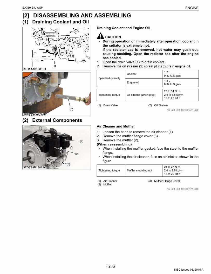
ENGINEEA330-E4, WSM
1-S23
[2] DISASSEMBLING AND ASSEMBLING(1) Draining Coolant and Oil
Draining Coolant and Engine Oil
CAUTION• During operation or immediately after operation, coolant in
the radiator is extremely hot.If the radiator cap is removed, hot water may gush out,causing scalding. Open the radiator cap after the enginehas cooled.
1. Open the drain valve (1) to drain coolant.2. Remove the oil strainer (2) (drain plug) to drain engine oil.
9Y1211018ENS0024US0
(2) External ComponentsAir Cleaner and Muffler
1. Loosen the band to remove the air cleaner (1).2. Remove the muffler flange cover (3).3. Remove the muffler (2).(When reassembling)• When installing the muffler gasket, face the steel to the muffler
flange.• When installing the air cleaner, face an air inlet as shown in the
figure.
9Y1211018ENS0025US0
Specified quantity
Coolant1.2 L0.32 U.S.gals
Engine oil1.3 L0.34 U.S.gals
Tightening torque Oil strainer (Drain plug)25 to 34 N·m2.5 to 3.5 kgf·m18 to 25 lbf·ft
(1) Drain Valve (2) Oil Strainer
Tightening torque Muffler mounting nut24 to 27 N·m2.4 to 2.8 kgf·m18 to 20 lbf·ft
(1) Air Cleaner(2) Muffler
(3) Muffler Flange Cover
KiSC issued 05, 2015 A

ENGINEEA330-E4, WSM
1-S24
Fuel Tank and Filter
1. Close the fuel valve (7) as shown in the photograph.2. Remove the engine hook (1) and radiator cover (2).3. Disconnect the overflow hose (3).4. Remove the eye joint bolt of the injection pump to detach the
fuel hose 2 (4).5. Remove the fuel filter mounting screw (8).6. Remove the fuel tank (5), fuel filter and hose as an unit.7. Remove the radiator net (6).(When reassembling)• Lap the overflow hose (3) below the radiator cover (2) as shown
in the photograph.• Set the hose clamps securely.
9Y1211018ENS0026US0
Wire Harness
1. Disconnect the fan leads (1).(When reassembling)• The lead wire must be grounded at particular locations as
illustrated.
9Y1211018ENS0027US0
Fan Cover and Starter
1. Disconnect the glow plug cord (4).2. Remove the flywheel cover (2).3. Remove the fan cover (3).4. Remove the starter (1), wire harness and battery cable as an
unit.
9Y1211018ENS0028US0
Cooling Fan
1. Remove the tension pulley (2).2. Remove the cooling fan assembly (1).(When reassembling)• Adjust the fan belt tension to the factory specifications.
9Y1211018ENS0029US0
Tightening torqueInjection pump eye joint bolt
25 to 29 N·m2.5 to 3.0 kgf·m18 to 21 lbf·ft
(1) Engine Hook(2) Radiator Cover(3) Overflow Hose(4) Fuel Hose 2
(5) Fuel Tank(6) Radiator Net(7) Fuel Valve(8) Fuel Filter Mounting Screw
Tightening torque Glow plug terminal nut0.98 to 1.7 N·m0.10 to 0.18 kgf·m0.73 to 1.3 lbf·ft
(1) Fan Lead
(1) Starter(2) Flywheel Cover
(3) Fan Cover(4) Glow Plug Cord
(1) Cooling Fan Assembly (2) Tension Pulley
KiSC issued 05, 2015 A

ENGINEEA330-E4, WSM
1-S25
Radiator
(When reassembling)• Apply liquid gasket (Three Bond 1102 or equivalent) to the both
sides of radiator gasket (2).
9Y1211018ENS0030US0
Tightening torqueRadiator mounting screw / nut
5.9 to 7.8 N·m0.60 to 0.80 kgf·m4.4 to 5.7 lbf·ft
(1) Radiator Assembly (2) Radiator Gasket
KiSC issued 05, 2015 A

ENGINEEA330-E4, WSM
1-S26
(3) Cylinder Head
9Y1211018ENS0031US0
Injection Pipe and Nozzle Holder
1. Remove the injection pipe (3).2. Remove the nozzle holder assembly (1) with a socket wrench
and remove heat seal and the copper gasket.3. Remove the glow plug (2).(When reassembling)• When reassembling the nozzle holder, take care that no carbon
or dirt gets in.• Replace the copper gasket and heat seal with a new one.
9Y1211018ENS0032US0
(1) Nozzle Holder(2) Injection Pipe(3) Decompress Hole Cover(4) Cylinder Head Cover(5) Rocker Arm Bushing(6) Rocker Arm(7) Rocker Arm Bracket(8) Valve Cap(9) Valve Spring Collet(10) Valve Spring Retainer(11) Valve Spring(12) Exhaust Valve Guide(13) Exhaust Valve(14) Decompress Shaft(15) Intake Valve Guide(16) Cylinder Head(17) Cylinder Head Gasket(18) Intake Valve(19) Drain Valve(20) Glow Plug(21) Heat Seal
Tightening torque
Nozzle holder assembly49 to 68 N·m5.0 to 7.0 kgf·m37 to 50 lbf·ft
Injection pipe retaining nut25 to 34 N·m2.5 to 3.5 kgf·m18 to 25 lbf·ft
Glow plug7.9 to 14 N·m0.80 to 1.5 kgf·m5.8 to 10 lbf·ft
(1) Nozzle Holder Assembly(2) Glow Plug
(3) Injection Pipe(4) Pipe Clamp Mounting Screw
KiSC issued 05, 2015 A

ENGINEEA330-E4, WSM
1-S27
Nozzle Heat Seal Service Removal Procedure
IMPORTANT• Use a plus (phillips head) screw driver that has a Dia. which
is bigger than the heat seal hole (Approx. 6 mm (1/4 in.).1. Drive screw driver lightly into the heat seal hole.2. Turn screw driver three or four times each way.3. While turning the screw driver, slowly pull the heat seal out
together with the injection nozzle gasket.
If the heat seal drops, repeat the above procedure. Heat sealand injection nozzle gasket must be changed when the injectionnozzle is removed for cleaning or for service.
9Y1211018ENS0033US0
Nozzle Holder
1. Secure the nozzle retaining nut (7) with a vise.2. Remove the nozzle holder (1), and take out parts inside.(When reassembling)• Assemble the nozzle in clean fuel oil.• Install the push rod (4), noting its direction.• After assembling the nozzle, be sure to adjust the fuel injection
pressure.
9Y1211018ENS0034US0
Cylinder Head Cover
1. Remove the cylinder head cover (1).(When reassembling)• After reassembling the head cover, adjust decompression
device.
9Y1211018ENS0035US0
(1) Plus Screw Driver(2) Injection Nozzle
(3) Injection Nozzle Gasket(4) Heat Seal
Tightening torque
Nozzle holder35 to 39 N·m3.5 to 4.0 kgf·m26 to 28 lbf·ft
Nozzle holder assembly49 to 68 N·m5.0 to 7.0 kgf·m37 to 50 lbf·ft
(1) Nozzle Holder(2) Adjusting Washer(3) Nozzle Spring(4) Push Rod
(5) Distance Piece(6) Nozzle Piece(7) Nozzle Retaining Nut
Tightening torque Head cover mounting nut9.8 to 10 N·m1.0 to 1.1 kgf·m7.3 to 7.9 lbf·ft
(1) Cylinder Head Cover
KiSC issued 05, 2015 A

ENGINEEA330-E4, WSM
1-S28
Rocker Arm Bracket and Push Rod
1. Remove the rocker arm bracket (1) and rocker arms together.2. Pull out the push rods (2).(When reassembling)• Apply engine oil to the rocker arm bushing bore and nut thread.• Insert the push rod into groove of tappet securely as shown in
the figure.• After tightening bracket mounting nut to the specified torque,
check that the rocker arm smoothly.
NOTE• Do not keep the push rods apart from the rocker arms while
tightening the nut.
IMPORTANT• The valve clearance must be adjusted after the rocker arm
is installed.
9Y1211018ENS0036US0
Cylinder Head
1. Remove the screws of tension bolt guide (1).2. Remove the air cleaner flange (2).3. Remove the cylinder head.(When reassembling)• Replace on the O-ring (3) between cylinder block and cylinder
head with a new one.• Replace the head gasket with a new one.• When installing the new head gasket, be careful of the
installation direction.
IMPORTANT• Gradually tighten the nuts in three passes in the order of (a)
to (f) as shown in the figure. After tuning the engine formore than 30 minutes, be sure to retighten the head nut.
• The valve clearance must be adjusted after the cylinderhead is installed.
9Y1211018ENS0037US0
Tightening torqueRocker arm bracket mounting nut
17 to 20 N·m1.7 to 2.1 kgf·m13 to 15 lbf·ft
(1) Rocker Arm Bracket(2) Push Rod
(3) Tappet
Tightening torque Cylinder head mounting nut57 to 61 N·m5.8 to 6.3 kgf·m42 to 45 lbf·ft
(1) Tension Bolt Guide(2) Air Cleaner Flange
(3) O-ring
KiSC issued 05, 2015 A

ENGINEEA330-E4, WSM
1-S29
Valve
1. Remove the valve caps (5).2. Remove the valve spring collets (4) with a valve lifter (6).3. Remove the valve spring retainers (3), valve springs (2) and
valves (1).(When reassembling)• Wash the valve stem and valve guide hole, and apply engine oil
sufficiently.• After installing the valve spring collets, lightly tap the stem to
assure proper fit with a plastic hammer.
9Y1211018ENS0038US0
(1) Valve(2) Valve Spring(3) Valve Spring Retainer
(4) Valve Spring Collet(5) Valve Cap(6) Valve Lifter
KiSC issued 05, 2015 A

ENGINEEA330-E4, WSM
1-S30
(4) Gear Case
9Y1211018ENS0039US0
(1) Balancer(2) Balancer Gear 2(3) Balancer Gear 1(4) Balancer Gear 3(5) Balancer Bearing Retainer
(6) Idle Gear Shaft(7) Idle Gear(8) Camshaft(9) Camshaft Gear
(10) Camshaft Stopper(11) Breather Assembly(12) Breather Oil Guard(13) Governor
(14) Injection Pump Assembly(15) Pump Adjusting Shim(16) Gear Case(17) Oil Pump Rotor Assembly
KiSC issued 05, 2015 A

ENGINEEA330-E4, WSM
1-S31
Injection Pump
1. Remove the injection pump mounting screws.2. Move the speed control lever (3) and align the control rack pin
(1) and notch (2) on the gear case to remove the injection pump.
NOTE• Record the number of injection timing adjusting shims
used to adjust the injection timing.(When reassembling)• Apply a thin coat of liquid gasket (Three bond 1215 or
equivalent) to the shim.
IMPORTANT• Insert the same number of shims as used before, install the
pump and then check the injection timing.• Correctly fit the control rack pin (1) into the groove of the
governor lever (4).
9Y1211018ENS0040US0
Oil Pump Cover and Oil Pump (If necessary)
1. Remove the oil pump cover.2. Remove the gear case.3. Push out the inner rotor shaft from inside of the gear case.(When reassembling)• Apply engine oil in each section (gear case oil pump body, inner
rotor shaft, inner rotor, outer rotor.).
NOTE• After installing the gear case to the cylinder block, be sure
to fit the inner rotor shaft into the camshaft end groove.9Y1211018ENS0041US0
Gear Case
1. Remove the gear case.(When reassembling)• Dismount the inner rotor shaft of oil pump beforehand.• Replace the O-ring (1) of the oil gallery connection with a new
one.• Coat the gear case gasket with grease, and take case to avoid
any misalignment of the new O-ring or screw holes.
9Y1211018ENS0042US0
Tightening torqueInjection pump mounting screw
9.81 to 11.2 N·m1.00 to 1.15 kgf·m7.24 to 8.31 lbf·ft
(1) Control Rack Pin(2) Notch
(3) Speed Control Lever(4) Governor Lever
Tightening torque Gear case mounting screw9.81 to 11.2 N·m1.00 to 1.15 kgf·m7.24 to 8.31 lbf·ft
(1) O-ring
KiSC issued 05, 2015 A

ENGINEEA330-E4, WSM
1-S32
Cam Gear and Camshaft
NOTE• Before disassembling, check the backlash of each gears.
Also check them during reassembly.1. Remove the lock plate mounting screw (2).2. Remove the cam gear (1) and camshaft together.(When reassembling)
IMPORTANT• Align the alignment marks of each gears.
9Y1211018ENS0043US0
Idle Gear
1. Draw out the external snap ring (3) on the idle gear shaft (6) andtake out the idle gear (2).
2. Alternatively, remove the idle gear shaft screw, and the take outthe idle gear and gear shaft together.
3. Remove the balancer bearing retainer (5).(When reassembling)
NOTE• Align the alignment marks of the idle gear, balancer gear (4)
and crank gear (1).
9Y1211018ENS0044US0
Crankcase Cover
1. Remove the crankcase cover (1).(When reassembling)• Tighten the crankcase cover mounting screws gradually in the
order of (a) to (h) as shown in the figure.
9Y1211018ENS0045US0
(1) Cam Gear (2) Lock Plate Mounting Screw
Tightening torque Idle gear shaft screw9.81 to 11.2 N·m1.00 to 1.15 kgf·m7.24 to 8.31 lbf·ft
(1) Crank Gear(2) Idle Gear(3) External Snap Ring
(4) Balancer Gear(5) Balancer Bearing Retainer(6) Idle Gear Shaft
Tightening torqueCrankcase cover mounting screw
7.9 to 9.3 N·m0.80 to 0.95 kgf·m5.8 to 6.8 lbf·ft
(1) Crankcase Cover
KiSC issued 05, 2015 A

ENGINEEA330-E4, WSM
1-S33
Balancer Gear and Balancer
NOTE• Before disassembling, check the backlash of the balancer
gears 1 (2) and 2 (1). Also check it during reassembly.1. From the inside of the cylinder block place a brass rod against
the end of the balancer and tap it off to the gear case side witha hammer.
(When reassembling)• If the piston and the connecting rod have been removed, it is
easier to reassemble the connecting rod cap first, and thenproceed to the balancer gear reassembly.
IMPORTANT• Align the alignment marks of the balancer gears 1 (2) and 2
(1).
9Y1211018ENS0046US0
Reassembling Procedure of Gears
1. Set the crankshaft so the crank pin comes directly to the left sideas viewed from the gear.
2. Align the alignment marks of balancer gear 2 (3) and balancergear 1 (5).
3. Turn the balancer gear by 3.14 rad (180 °) to the position asshown in the figure.
4. Align the alignment marks of the crank gear (2), cam gear (1)and balancer gear 3 (4), and reassemble the idle gear (6), (7).
9Y1211018ENS0047US0
Governor Lever
1. Detach the governor spring (3) and spring (4) from the governorlever (1).
2. Remove the screw (2) and pull out the governor lever shafttoward the breather side.
3. Remove the governor lever.
NOTE• Do not lose the ball onto the governor shaft in the process.
9Y1211018ENS0048US0
Breather
1. Remove the breather mounting screw (1) to remove thebreather assembly.
(When reassembling)• Install the breather assembly with the valve hole (3) in the
opposite side of the oil escape groove (2).
9Y1211018ENS0049US0
(1) Balancer Gear 2 (2) Balancer Gear 1
(1) Cam Gear(2) Crank Gear(3) Balancer Gear 2(4) Balancer Gear 3
(5) Balancer Gear 1(6) Idle Gear (45T)(7) Idle Gear (21T)
(1) Governor Lever(2) Screw
(3) Governor Spring(4) Idling Spring
(1) Mounting Screw(2) Oil Escape Groove
(3) Valve Hole
KiSC issued 05, 2015 A

ENGINEEA330-E4, WSM
1-S34
Governor Weight
1. Remove the governor weight (1) and governor weight holder (2)together.
9Y1211018ENS0050US0
Tightening torqueGovernor weight holder mounting screw
9.81 to 11.2 N·m1.00 to 1.15 kgf·m7.24 to 8.31 lbf·ft
(1) Governor Weight (2) Governor Weight Holder
KiSC issued 05, 2015 A

ENGINEEA330-E4, WSM
1-S35
(5) Piston and Connecting Rod
9Y1211018ENS0051US0
Connecting Rod Cap
1. Set the piston in the bottom dead center.2. Remove the connecting rod screws (2) to remove the
connecting rod cap (1).
NOTE• Untighten rod screws slowly and equally.
(When reassembling)• Apply engine oil to the crank pin bearings and connecting rod
screws.• The connecting rod cap must be installed with the stamped
mark facing the radiator so the mark (3) of the connecting rodand that of the connecting rod cap are aligned.
IMPORTANT• Screw the rod screws light by hand and fully insert it. If it
cannot be screwed in lightly by hand, clean the thread. If itis still hard to screw, replace the screw.
9Y1211018ENS0052US0
(1) Piston(2) Connecting Rod(3) Crank PIn Bearing(4) Connecting Rod Cap(5) Connecting Rod Screw(6) Crankcase Cover(7) Piston RIng Assembly(8) PIston Pin(9) Piston Pin Bushing
Tightening torque Connecting rod screw27 to 30 N·m2.7 to 3.1 kgf·m20 to 22 lbf·ft
(1) Connecting Rod Cap(2) Connecting Rod Screw
(3) Mark
KiSC issued 05, 2015 A

ENGINEEA330-E4, WSM
1-S36
Piston and Connecting Rod
1. Turn the flywheel and bring the piston to the top dead center.2. Pull out the piston upward by tapping it from the bottom of the
cylinder block with the grip of a hammer.(When reassembling)• Before installing the piston into the cylinder, apply enough
engine oil to the cylinder liner wall.• When inserting the piston into the cylinder, face the mark on the
connecting rod to the radiator side.• When inserting the piston into the cylinder, place the top ring
gap (b) on the opposite side of the combustion chamber (a), andstagger the second ring gap (c) and oil ring gap (d) marking aright angle from the top ring gap.
9Y1211018ENS0053US0
(1) Piston Ring Compressor
(a) Combustion Chamber(b) Top Ring Gap(c) Second Ring Gap(d) Oil Ring Gap
A: 1.6 rad (90 °)B: 1.6 rad (90 °)C: 0.31 rad (18 °)
KiSC issued 05, 2015 A

ENGINEEA330-E4, WSM
1-S37
Piston Ring and Connecting Rod
1. Remove the piston rings with a piston ring tool.2. Put the parting mark (8) on the piston head as shown in the
photograph.3. Remove the piston pin (7), and separate the connecting rod (6)
from the piston (1).(When reassembling)• Clean all the parts before assembling.• When installing the ring, assemble the rings so that the
manufacturer's mark R near the gap faces the top of piston.• When installing the oil ring onto the piston, place the expander
joint (10) on the opposite side of the oil ring gap (11).• Apply engine oil to the piston pin, and insert it to the piston.• When installing the connecting rod to the piston, align the
stamped mark (9) on the connecting rod to the parting mark (8).
9Y1211018ENS0054US0
(1) Piston(2) Top Ring(3) Second Ring(4) Oil Ring(5) Piston Pin Snap Ring(6) Connecting Rod(7) Piston Pin
(8) Parting Mark(9) Mark(10) Expander Joint(11) Oil Ring Gap(12) Manufacturer's Mark
(a) 3.14 rad (180 °)
KiSC issued 05, 2015 A

ENGINEEA330-E4, WSM
1-S38
(6) Flywheel and Crankshaft
9Y1211018ENS0055US0
Pulley Shaft
1. Place a wood block, etc. to prevent the crankshaft from turning,and remove the pulley shaft (or the pulley).
9Y1211018ENS0056US0
Flywheel Nut
1. Stretch the lock washer.2. Lock the flywheel nut to turn with a flywheel stopper.3. Remove the flywheel nut with a socket wrench 36 mm.(When reassembling)• Apply molybdenum disulfide oil to the flywheel nut seat and
thread, and tighten the flywheel nut to the specified torque.• Be sure to bend up the lock washer (1) to prevent loosening as
shown in the figure.
9Y1211018ENS0057US0
(1) Pulley Shaft(2) Flywheel Nut(3) Flywheel(4) Oil Seal(5) O-ring(6) Oil Filler Ring(7) Internal Snap Ring(8) Main Bearing Case(9) O-ring(10) Main Bearing Retainer(11) Main Bearing 2(12) Crankshaft(13) Main Bearing 1(14) Crankshaft Gear(15) Ring Gear
Tightening torque Flywheel nut197 to 215 N·m20.0 to 22.0 kgf·m145 to 159 lbf·ft
(1) Lock Washer
KiSC issued 05, 2015 A

ENGINEEA330-E4, WSM
1-S39
Flywheel
1. Set a flywheel puller (Code No. 17916-04052) and remove itwith the flywheel.
IMPORTANT• Clean the flywheel and crankshaft tapered section to be
free from any dirt or chips. Also take care so that oil doesnot stick to the crankshaft tapered section.
9Y1211018ENS0058US0
Crankshaft and Main Bearing Case
1. Remove the flywheel key.2. Remove the bolts of main bearing case.3. Insert the tip of a screwdriver in the gap "A" between the
bearing case and the cylinder block (as shown with in thephoto). Then, by prying the screwdriver to left and right evenly,pull out the bearing and the crank shaft together.
(When reassembling)• Check that the O-ring is not damaged and apply a light coating
of oil to the ring.• Tighten the main bearing case retaining bolts gradually in the
order of (a) to (i) as shown in the figure.
9Y1211018ENS0059US0
Tightening torqueMain bearing case mounting screw / nut
9.81 to 11.2 N·m1.00 to 1.15 kgf·m7.24 to 8.31 lbf·ft
A: Gap
KiSC issued 05, 2015 A
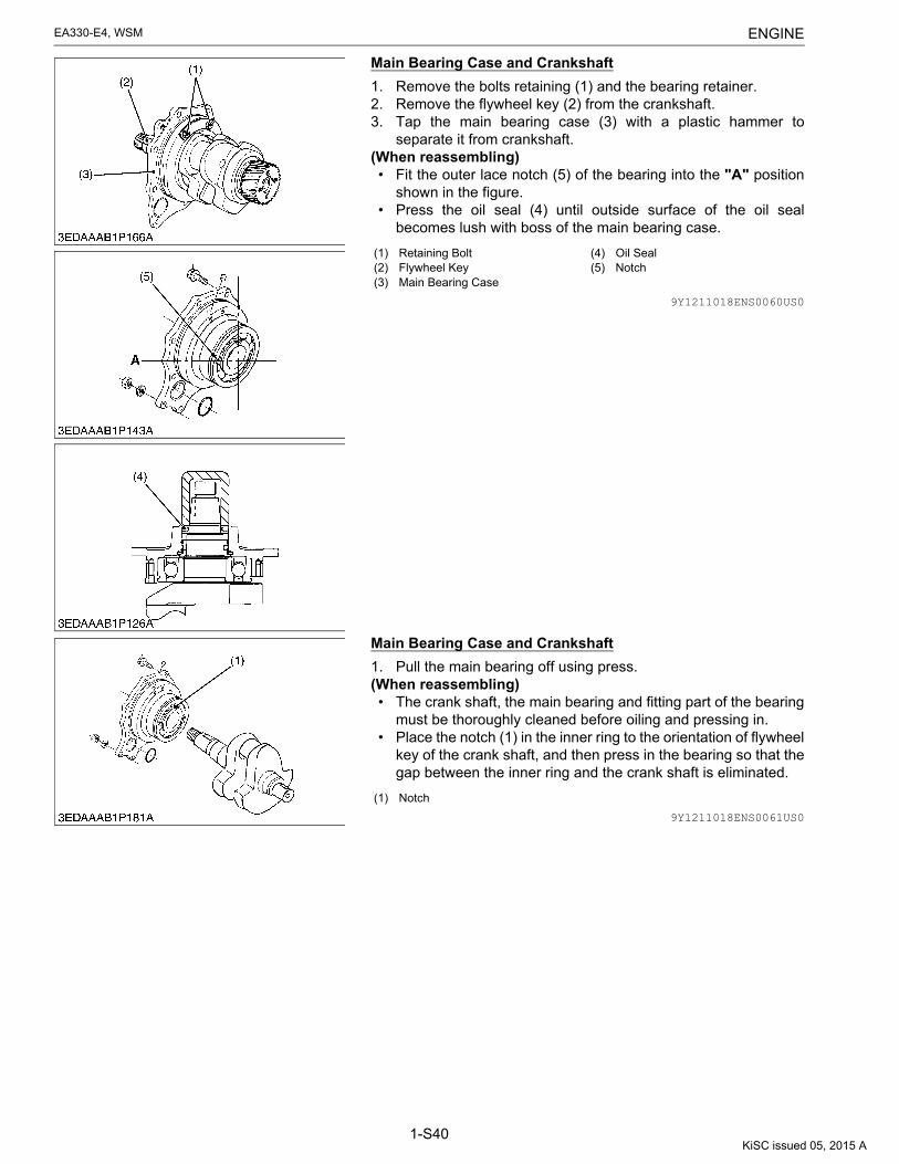
ENGINEEA330-E4, WSM
1-S40
Main Bearing Case and Crankshaft
1. Remove the bolts retaining (1) and the bearing retainer.2. Remove the flywheel key (2) from the crankshaft.3. Tap the main bearing case (3) with a plastic hammer to
separate it from crankshaft.(When reassembling)• Fit the outer lace notch (5) of the bearing into the "A" position
shown in the figure.• Press the oil seal (4) until outside surface of the oil seal
becomes lush with boss of the main bearing case.
9Y1211018ENS0060US0
Main Bearing Case and Crankshaft
1. Pull the main bearing off using press.(When reassembling)• The crank shaft, the main bearing and fitting part of the bearing
must be thoroughly cleaned before oiling and pressing in.• Place the notch (1) in the inner ring to the orientation of flywheel
key of the crank shaft, and then press in the bearing so that thegap between the inner ring and the crank shaft is eliminated.
9Y1211018ENS0061US0
(1) Retaining Bolt(2) Flywheel Key(3) Main Bearing Case
(4) Oil Seal(5) Notch
(1) Notch
KiSC issued 05, 2015 A

ENGINEEA330-E4, WSM
1-S41
Crank Gear and Main Bearing 1
1. Secure the crankshaft with a vise and installing a crank gearpuller.
2. Pull out the crank gear.(When reassembling)• Tap the outer ring (5) of the main bearing 1 (roller bearing near
the gear case) into the cylinder block (3) until the end surface ofthe outer ring (5) is flush with that of the cylinder block (3).
IMPORTANT• Tap the outer ring of the bearing carefully without
damaging the roller raceway surface (4).• Confirm that main bearing is press-fitted so that the gap
between the crankshaft end surface and main bearing sidesurface is 0 mm (0 in.).
• Press-fit the crank gear (6) so that the gap between thebearing side and bearing inner side is 0 mm (0 in.).
9Y1211018ENS0062US0
Tappet
1. Pull out the tappet (1).(When reassembling)• Before installing the tappet, apply engine oil around it.
9Y1211018ENS0063US0
(1) Gear Case Surface(2) Inserting Tool(3) Cylinder Block(4) Roller Raceway Surface
(5) Roller Bearing Outer Ring(6) Crank Gear
A: 0 mm (0 in.)
(1) Tappet
KiSC issued 05, 2015 A

ENGINEEA330-E4, WSM
1-S42
(7) StarterMagnet Switch
1. Disconnect the connecting lead.2. Remove the mounting nut.3. Remove the magnet switch (1) by sliding it up so that it is
disconnected from the drive lever.
9Y1211018ENS0064US0
Armature Brake
1. Remove the end frame cap (1).2. Remove the brake shoe (2).3. Remove the brake spring (3).4. Remove the gasket (4).(When reassembling)• After reassembling the brake shoe (2), adjust the shaft thrust
gap.
9Y1211018ENS0065US0
End Frame
1. Remove the two through bolts.2. Remove the end frame (1).
9Y1211018ENS0066US0
Brush Holder
1. Draw out the brush from the holder while holding the spring up.2. Remove the brush holder (1).(When reassembling)• When replacing the spring, install it by referring to the figure.• Do not contact the brush's positive lead with the body.
9Y1211018ENS0067US0
(1) Magnet Switch
(1) End Frame Cap(2) Brake Shoe
(3) Brake Spring(4) Gasket
(1) End Frame
(1) Brush Holder(2) Spring Hanger
(3) Attach the brush spring in this method
(4) Brush
KiSC issued 05, 2015 A

ENGINEEA330-E4, WSM
1-S43
Yoke
1. Draw out the yoke (1) from the drive end frame.(When reassembling)• Install the yoke, nothing the location of dowel pin.
9Y1211018ENS0068US0
Armature
1. Draw out the armature (2) with the drive lever (1).(When reassembling)• Install the drive lever, nothing its direction.
9Y1211018ENS0069US0
(1) Yoke
(1) Drive Lever(2) Armature
(3) Drive End Frame
KiSC issued 05, 2015 A
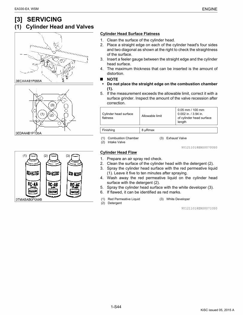
ENGINEEA330-E4, WSM
1-S44
[3] SERVICING(1) Cylinder Head and Valves
Cylinder Head Surface Flatness
1. Clean the surface of the cylinder head.2. Place a straight edge on each of the cylinder head's four sides
and two diagonal as shown at the right to check the straightnessof the surface.
3. Insert a feeler gauge between the straight edge and the cylinderhead surface.
4. The maximum thickness that can be inserted is the amount ofdistortion.
NOTE• Do not place the straight edge on the combustion chamber
(1).5. If the measurement exceeds the allowable limit, correct it with a
surface grinder. Inspect the amount of the valve recession aftercorrection.
9Y1211018ENS0070US0
Cylinder Head Flaw
1. Prepare an air spray red check.2. Clean the surface of the cylinder head with the detergent (2).3. Spray the cylinder head surface with the red permeative liquid
(1). Leave it five to ten minutes after spraying.4. Wash away the red permeative liquid on the cylinder head
surface with the detergent (2).5. Spray the cylinder head surface with the white developer (3).6. If flawed, it can be identified as red marks.
9Y1211018ENS0071US0
Cylinder head surface flatness
Allowable limit
0.05 mm / 100 mm0.002 in. / 3.94 in.of cylinder head surface length
Finishing 8 μRmax
(1) Combustion Chamber(2) Intake Valve
(3) Exhaust Valve
(1) Red Permeative Liquid(2) Detergent
(3) White Developer
KiSC issued 05, 2015 A
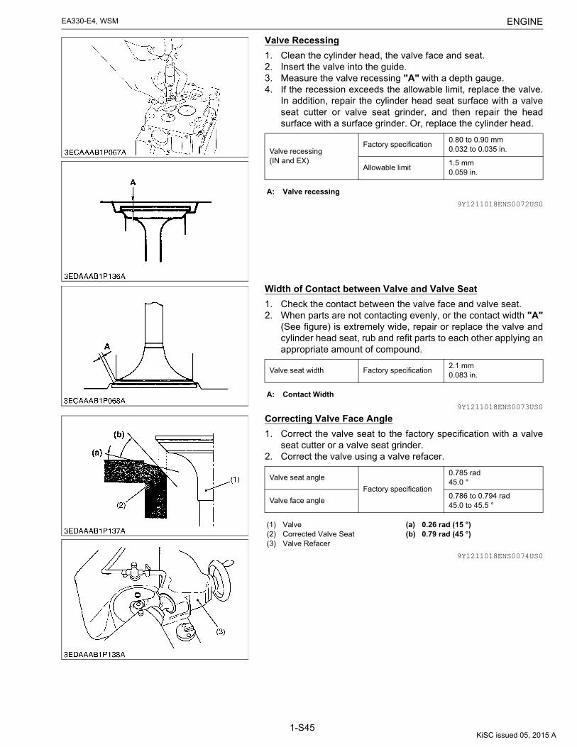
ENGINEEA330-E4, WSM
1-S45
Valve Recessing
1. Clean the cylinder head, the valve face and seat.2. Insert the valve into the guide.3. Measure the valve recessing "A" with a depth gauge.4. If the recession exceeds the allowable limit, replace the valve.
In addition, repair the cylinder head seat surface with a valveseat cutter or valve seat grinder, and then repair the headsurface with a surface grinder. Or, replace the cylinder head.
9Y1211018ENS0072US0
Width of Contact between Valve and Valve Seat
1. Check the contact between the valve face and valve seat.2. When parts are not contacting evenly, or the contact width "A"
(See figure) is extremely wide, repair or replace the valve andcylinder head seat, rub and refit parts to each other applying anappropriate amount of compound.
9Y1211018ENS0073US0
Correcting Valve Face Angle
1. Correct the valve seat to the factory specification with a valveseat cutter or a valve seat grinder.
2. Correct the valve using a valve refacer.
9Y1211018ENS0074US0
Valve recessing(IN and EX)
Factory specification0.80 to 0.90 mm0.032 to 0.035 in.
Allowable limit1.5 mm0.059 in.
A: Valve recessing
Valve seat width Factory specification2.1 mm0.083 in.
A: Contact Width
Valve seat angle
Factory specification
0.785 rad45.0 °
Valve face angle0.786 to 0.794 rad45.0 to 45.5 °
(1) Valve(2) Corrected Valve Seat(3) Valve Refacer
(a) 0.26 rad (15 °)(b) 0.79 rad (45 °)
KiSC issued 05, 2015 A

ENGINEEA330-E4, WSM
1-S46
Correcting Procedure for Valve Seat
NOTE• Always try to minimize the valve seat recession.
1. Correct the valve seat surface with a 0.79 rad (45 °) valve seatcutter.
2. Place the valve and visually check the contact position betweenthe valve face and valve seat with red lead.(If the valve has been used for a long period of time, the seattends to come into contact with the upper side of the valveface.).
3. Cut the seat with a 0.26 rad (15 °) valve seat cutter so that thevalve seat width makes contact in the same dimensions to thevalve face width.
4. Cut the seat with a 0.79 rad (45 °) valve seat cutter again, andvisually recheck the contact between the valve and seat.
5. Repeat steps "B" and "C" until the correct contact is achieved.6. Continue lapping until the seated rate is more than 70% of the
total contact area.
9Y1211018ENS0075US0
Correcting Valve Seating (Valve Lapping)
1. Apply compound evenly to the valve lapping surface.2. Insert the valve into the valve guide. Lap the valve onto its seat
with a valve flapper.3. After lapping the valve, wash the compound away and apply oil,
then repeat valve lapping with oil.4. Apply prussian blue to the contact surface to check the seated
rate. If it is less than 70 %, repeat valve lapping again.
IMPORTANT• When valve lapping is performed, be sure to check the
valve recessing and adjust the valve clearance afterassembling the valve.
9Y1211018ENS0076US0
Oil Clearance between Valve Stem and Valve Guide
1. Remove carbon from the valve guide bore.2. Measure the valve stem O.D. with an outside micrometer.3. Measure I.D. of the cylinder head valve guide at the most worn
part with a small hole gauge, and find the oil clearance.(Normally, a greater wear results in parallel to the rocker arm.).
4. If the clearance exceeds the allowable limit, replace the valveguide and valve.
9Y1211018ENS0077US0
(1) Valve Seat Cutter(2) Identical Dimensions(3) Seat Surface Width
(a) 0.26 rad (15 °)(b) 0.79 rad (45 °)(c) 0.79 rad (45 °)(d) 0.26 rad (15 °)(e) 0.79 rad (45 °)
A: 0.79 rad (45 °) CutterB: Contact CheckC: 0.26 rad (15 °) CutterD: 0.79 rad (45 °) CutterE: Contact Check
Oil clearance between valve stem and valve guide
Factory specification0.035 to 0.065 mm0.0014 to 0.0025 in.
Allowable limit0.1 mm0.004 in.
Valve stem O.D. Factory specification6.960 to 6.975 mm0.2741 to 0.2746 in.
Valve guide bore I.D. Factory specification7.010 to 7.025 mm0.2760 to 0.2765 in.
KiSC issued 05, 2015 A

ENGINEEA330-E4, WSM
1-S47
Replacing Valve Guide
(When removing)1. Press out valve guide with a valve guide replacing tool.(When installing)1. Clean the valve guide bore, and apply engine oil to it.2. Press in the valve guide until its flange contacts the cylinder
head.3. Provide an oil return hole in the exhaust valve with a drill.4. Ream precisely the bore of the valve guide to the specified
dimension in the table below.
IMPORTANT• Do not hit the valve guide with a hammer during
replacement.
9Y1211018ENS0078US0
Valve Spring Free Length and Tension
1. Measure the free length of the spring with vernier calipers.2. Place the spring on a spring compression tester and compress
to the specified length, and get the tension.3. If the measurement is less than the allowable limit, replace the
valve spring.
9Y1211018ENS0079US0
Valve guide bore I.D. Factory specification7.010 to 7.025 mm0.2760 to 0.2765 in.
Finishing 6.3 S
Free length
Factory specification34.5 mm1.36 in.
Allowable limit33.8 mm1.33 in.
Setting load / Setting length
Factory specification59 N / 31 mm6.0 kgf / 31 mm13 lbf / 1.2 in.
Allowable limit49 N / 31 mm5.0 kgf / 31 mm11 lbf / 1.2 in.
KiSC issued 05, 2015 A

ENGINEEA330-E4, WSM
1-S48
Valve Spring Tilt
1. Place the spring on the surface plate and a square at its side.2. Measure the free length "A" (See figure) by rotating spring.3. If the measurement exceeds the allowable limit, replace the
valve spring.
9Y1211018ENS0080US0
Oil Clearance between Rocker Arm Shaft and Rocker Arm
1. Measure the rocker arm shaft O.D. with an outside micrometer.2. Measure the rocker arm I.D. with an inside micrometer, and
calculate the oil clearance.3. If the clearance exceeds the allowable limit, replace the rocker
arm.
9Y1211018ENS0081US0
Oil Clearance between Tappet and Guide
1. Measure the tappet O.D. with a outside micrometer.2. Measure the tappet guide bore I.D. of the cylinder block with an
inside micrometer, and calculate the oil clearance.3. If the oil clearance exceeds the allowable limit or the sliding
surface is scored, replace the tappet.
9Y1211018ENS0082US0
Tilt B Allowable limit1.2 mm0.047 in.
A: Free Length B: Tilt
Oil clearance between rocker arm and shaft
Factory specification0.016 to 0.045 mm0.00063 to 0.0017 in.
Allowable limit0.15 mm0.0059 in.
Rocker arm shaft Factory specification10.973 to 10.984 mm0.43201 to 0.43244 in.
Rocker arm I.D. Allowable limit11.000 to 11.018 mm0.43307 to 0.43377 in.
Oil clearance between tappet and guide
Factory specification0.020 to 0.062 mm0.00079 to 0.0024 in.
Allowable limit0.15 mm0.0059 in.
Tappet O.D. Factory specification19.959 to 19.980 mm0.78579 to 0.78661 in.
Guide bore I.D. Factory specification20.000 to 20.021 mm0.78741 to 0.78822 in.
KiSC issued 05, 2015 A

ENGINEEA330-E4, WSM
1-S49
Push Rod Alignment
1. Check the both end of the push rod for cracks, damage andunusual wear.
2. Measure the bending of the push rod with a dial indicator.3. If the measurement exceeds the allowable limit, replace the
push rod.
9Y1211018ENS0083US0
Bending Allowable limit0.125 mm0.00492 in.
KiSC issued 05, 2015 A

ENGINEEA330-E4, WSM
1-S50
(2) Piston and Connecting RodPiston Skirt O.D.
1. Measure the piston skirt O.D. with an outside micrometer.(Measuring points are shown in the figure.)
2. If the measurement is less than the allowable limit, replace thepiston.
9Y1211018ENS0084US0
Piston Pin Bore
1. Measure the piston pin bore I.D. (lengthwise and widthwise ofthe piston) with a cylinder gauge.
2. If the measurement exceeds the allowable limit, replace thepiston.
9Y1211018ENS0085US0
Oil Clearance between Piston Pin and Bushing
1. Measure the piston pin O.D. with an outside micrometer.2. Measure the piston pin bushing I.D. with an inside micrometer,
and calculate the oil clearance.3. If the clearance exceeds the allowable limit, replace the
bushing.4. If the clearance still exceeds the allowable limit with new
bushing, replace the piston pin.
9Y1211018ENS0086US0
Piston skirt O.D.
Factory specification76.925 to 76.945 mm3.0286 to 3.0293 in.
Allowable limitCylinder liner I.D.−0.25 mm−0.0098 in.
Piston pin bore I.D.
Factory specification20.000 to 20.013 mm0.78741 to 0.78791 in.
Allowable limit20.04 mm0.7890 in.
Oil clearance between piston pin and bushing
Factory specification0.014 to 0.038 mm0.00056 to 0.0014 in.
Allowable limit0.15 mm0.0059 in.
Piston pin O.D. Factory specification20.002 to 20.011 mm0.78748 to 0.78783 in.
Small end bushing I.D. Factory specification20.025 to 20.040 mm0.78839 to 0.78897 in.
KiSC issued 05, 2015 A

ENGINEEA330-E4, WSM
1-S51
Replacing Piston Pin Bushing
(When removing)1. Press out piston pin bushing with a piston pin bushing replacing
tool.(When installing)1. Clean the new bushing and bore, and apply engine oil to them.2. Insert a new bushing onto the tool and press-fit it with the press
so that the oil holes (2) are aligned as shown in the figure, untilit is flush with the connecting rod.
3. Drill a hole to the bushing with aligning the oil hole (2) ofconnecting rod using 4.0 mm dia. (0.16 in. dia.) drill.
NOTE• Be sure to chamfer the oil hole circumference with an oil
stone.• Check that the seam (1) of the bushing positions as shown
in the figure.(Reference)• Service parts dimension:
9Y1211018ENS0087US0
Connecting Rod Alignment
NOTE• Since the piston pin bushing I.D. is the basis of this check,
check bushing for wear beforehand.1. Remove the connecting rod bearing and install the bearing cap.2. Install the piston pin into the connecting rod.3. Install the connecting rod on the connecting rod alignment tool.4. Put a gauge over the piston pin and move it against the face
plate.5. If the gauge does not fit squarely against the face plate,
measure the space between the pin of the gauge and the faceplate.
6. If the measurement exceeds the allowable limit, replace theconnecting rod.
9Y1211018ENS0088US0
Oil clearance between piston pin and bushing
Factory specification0.015 to 0.075 mm0.00059 to 0.0029 in.
Allowable limit0.15 mm0.0059 in.
Piston pin O.D.
Factory specification
20.002 to 20.011 mm0.78748 to 0.78783 in.
Piston pin bushing I.D.20.026 to 20.077 mm0.78843 to 0.79043 in.
(1) Seam(2) Oil Hole
(A) When Removing(B) When Installing(a) 0.79 rad (45 °)
Bent "A"
Allowable limit
0.05 mm / 100 mm0.002 in. / 3.94 in.
Twist "B"0.05 mm /100 mm0.002 in. / 3.94 in.
KiSC issued 05, 2015 A

ENGINEEA330-E4, WSM
1-S52
Piston Ring Gap
1. Insert the piston ring into the lower part of the liner (Measuringpoints are shown in the figure) with a piston ring compressorand the piston.
2. Measure the ring gap with a feeler gauge.3. If the gap exceeds the allowable limit, replace the piston ring.
9Y1211018ENS0089US0
Clearance between Piston Ring and Ring Groove
1. Clean the rings and the ring grooves, and install each ring intoits groove.
2. Measure the clearance between the ring and the groove with afeeler gauge.
3. If the clearance exceeds the allowable limit, replace the pistonring.
4. If the clearance still exceeds the allowable limit with new ring,replace the piston.
NOTE• As the top ring is a Keystone type, it cannot be measured
by this method.9Y1211018ENS0090US0
Ring gap
Factory specifica-tion
Top ringSecond ring
0.30 to 0.45 mm0.012 to 0.017 in.
Oil ring0.25 to 0.40 mm0.0099 to 0.015 in.
Allowable limit1.2 mm0.047 in.
(a) Approx. 90 mm (3.5 in.)
Clearance between piston ring and ring groove
Factory specifica-tion
Top ring Keystone ring
Second ring
0.0850 to 0.112 mm0.00335 to 0.00440 in.
Oil ring0.020 to 0.055 mm0.00079 to 0.0021 in.
Allowable limit
Second ring
0.2 mm0.008 in.
Oil ring0.15 mm0.0059 in.
KiSC issued 05, 2015 A

ENGINEEA330-E4, WSM
1-S53
(3) CrankshaftOil Clearance between Crank Pin and Bearing
1. Put a strip of press gauge lengthwise on the center of the crankpin in each direction as shown in the figure.
2. Install the connecting rod cap and tighten the screws to thespecified torque (27 to 30 N·m, 2.7 to 3.1 kgf·m, 20 to 22 lbf·ft)once, and remove the cap again.
3. Measure the amount of the flattening with the scale and get theoil clearance.
4. If the clearance exceeds the allowable limit, replace the bearing.
NOTE• Do not insert the press gauge into the crank pin oil hole.• Fasten the crankshaft so that it does not turn.
(Reference)• When the crank pin wears further over a long period of use and
oil clearance exceeds the allowable limit after replacing thestandard bearing, use a undersize bearing. Machine the crankpin according to the following precautions.
9Y1211018ENS0091US0
Use of Under size Bearing and Crank Pin Correction
1. Be sure to correctly grind the corner radius of the crank pin.2. Be sure to chamfer the entire circumference of each oil hole,
using an oil stone.3. Be sure to precision finish the crank pin section to higher than
0.4S.
9Y1211018ENS0092US0
Oil clearance between crank pin and bearing
Factory specification0.019 to 0.077 mm0.00075 to 0.0030 in.
Allowable limit0.2 mm0.008 in.
Crank pin O.D.
Factory specification
36.959 to 36.975 mm1.4551 to 1.4557 in.
Crank pin bearing I.D.(When tightening)
36.994 to 37.036 mm1.4565 to 1.4581 in.
(a) 0.52 rad (30 °) (b) 0.52 rad (30 °)
0.2 mm (0.008 in.) 0.4 mm (0.02 in.)
Bearing Code No. 15531-2297-1 15531-2298-1
Bearing Name Crank pin bearing (0.2) Crank pin bearing (0.4)
Bearing Mark 0.2 US 0.4 US
Crankshaft machined Dimension D(See figure)
36.759 to 36.775 mm1.4472 to 1.4478 in.
36.559 to 36.575 mm1.4394 to 1.4399 in.
(1) Corner Radius 2.8 to 3.2 mm R(0.11 to 0.12 in. R)
(2) The End of the Oil Hole Should be Chamfered to 1.0 to 1.5mm R(0.040 to 0.059 in. R)
(3) Maker Mark(4) Manufacture's No.(5) Size
[A] Marking and Numbering on Under size Bearing
KiSC issued 05, 2015 A

ENGINEEA330-E4, WSM
1-S54
Crankshaft Side Clearance
1. Move the crankshaft to the flywheel side.2. Attach a dial gauge to the crankshaft (3).3. Measure the end play by pushing the crankshaft toward the
crank gear (5).4. If the measurement exceeds the allowable limit, replace the
main bearing retainer (1).5. If the new end play still exceeds the allowable limit, check main
bearings 2 (2) and 1 (4). If worn abnormally, replace mainbearings.
NOTE• When the end play is below the factory specifications, it
may be heavy turning or difficult starting, and when it isover, it may be vibration of the flywheel or knocking.
9Y1211018ENS0093US0
Oil Clearance between Crankshaft and Oil Filler Ring
1. Measure the crankshaft O.D. with an outside micrometer.2. Measure the oil filler ring I.D. with an inside micrometer, and
calculate the oil clearance.3. If the clearance exceeds the allowable limit, replace the oil filler
ring.
9Y1211018ENS0094US0
Crankshaft Alignment
1. Support the crankshaft with V block on the surface plate and seta dial indicator with its tip on the intermediate journal at rightangle.
2. Rotate the crankshaft on the V block and get the misalignment(half of the measurement).
3. If the misalignment exceeds the allowable limit, replace thecrankshaft.
9Y1211018ENS0095US0
Crankshaft side clearance
Factory specification0.050 to 0.46 mm0.0020 to 0.018 in.
Allowable limit0.56 mm0.022 in.
Thickness of main bearing retainer
Factory specification1.9 to 2.0 mm0.075 to 0.078 in.
(1) Main Bearing Retainer(2) Main Bearing 2(3) Crankshaft
(4) Main Bearing 1(5) Crank Gear
Oil clearance between crankshaft and oil filler ring
Factory specification0.025 to 0.066 mm0.00099 to 0.0025 in.
Allowable limit0.2 mm0.008 in.
Crankshaft O.D.
Factory specification
34.959 to 34.975 mm1.3764 to 1.3769 in.
Oil filler ring I.D.35.000 to 35.025 mm1.3780 to 1.3789 in.
Crankshaft alignment Allowable limit0.04 mm0.002 in.
KiSC issued 05, 2015 A

ENGINEEA330-E4, WSM
1-S55
(4) Timing Gear and CamshaftTiming Gear Backlash
1. Set a dial indicator (lever type) with its tip on the gear tooth.2. Move the gear to measure the backlash, holding its mating gear.3. If the backlash exceeds the allowable limit, check the oil
clearance of the shafts and gear.4. If the oil clearance is proper, replace the gear.
9Y1211018ENS0096US0
Side Clearance of Idle Gear
1. Pull the idle gear collar 2 (1) and push the idle gear (2) to eachend.
2. Measure the clearance "A" between the idle gear and idle gearcollar 2 with a feeler gauge.
3. If the clearance exceeds the allowable limit, replace the idlegear collar 1 (3).
9Y1211018ENS0097US0
Side Clearance of Cam Gear
1. Pull the cam gear (2) with the camshaft (1) to its end.2. Measure the clearance "A" between the cam gear (2) and
camshaft stopper (3).3. If the clearance exceeds the allowable limit, replace the
camshaft stopper.
9Y1211018ENS0098US0
Backlash
Factory specifica-tion
Barancer gear 1 × gear 2
0.0490 to 0.135 mm0.00193 to 0.00531 in.
Other gears
0.0430 to 0.130 mm0.00170 to 0.00511 in.
Allowable limit
All gears0.3 mm0.01 in.
Idle gear side clearance
Factory specification0.20 to 0.51 mm0.0079 to 0.020 in.
Allowable limit0.9 mm0.04 in.
Thickness of idle gear collar 1
Factory specification2.45 to 2.50 mm0.0965 to 0.0984 in.
(1) Idle Gear Collar 2(2) Idle Gear(2) Idle Gear Collar 1
A: Clearance
Cam gear side clearance
Factory specification0.0700 to 0.220 mm0.00276 to 0.00866 in.
Allowable limit0.3 mm0.001 in.
Thickness of camshaft stopper
Factory specification3.780 to 3.855 mm0.1489 to 0.1517 in.
(1) Camshaft(2) Cam Gear(2) Stopper
A: Clearance
KiSC issued 05, 2015 A

ENGINEEA330-E4, WSM
1-S56
Oil Clearance between Idle Gear Shaft and Bushing
1. Measure the idle gear shaft O.D. with an outside micrometer.2. Measure the idle gear bushings I.D. with an inside micrometer,
and calculate the oil clearance.3. If the clearance exceeds the allowable limit, replace the
bushing.4. If the clearance still exceeds the allowable limit with new
bushing, replace the idle gear shaft.
9Y1211018ENS0099US0
Replacing Idle Gear Bushing
(When removing)1. Press out the bushings with an idle gear bushing replacing tool.(When installing)1. Clean the new bushings and bore, and apply engine oil to them.2. Press in the bushing with an idle gear bushing replacing tool.(Reference)• Service parts dimension:
9Y1211018ENS0100US0
Oil clearance between idle gear shaft and bushing
Factory specification0.016 to 0.045 mm0.00063 to 0.0017 in.
Allowable limit0.1 mm0.004 in.
Idle gear shaft O.D.
Factory specification
17.973 to 17.984 mm0.70760 to 0.70803 in.
Idle gear bushing I.D.18.000 to 18.018 mm0.70867 to 0.70937 in.
Oil clearance between idle gear shaft and bushing
Factory specification0.016 to 0.078 mm0.00063 to 0.0030 in.
Allowable limit0.1 mm0.004 in.
Idle gear shaft O.D.
Factory specification
17.973 to 17.984 mm0.70760 to 0.70803 in.
Idle gear bushing I.D.18.000 to 18.048 mm0.70867 to 0.71055 in.
(A) When removing (B) When installing
KiSC issued 05, 2015 A

ENGINEEA330-E4, WSM
1-S57
Oil Clearance of Camshaft
1. Measure the camshaft journal O.D. with an outside micrometer.2. Measure the camshaft bore I.D. withe an inside micrometer and
calculate the oil clearance.3. If the clearance exceeds the allowable limit, replace the
camshaft.4. If the clearance still exceeds the allowable limit with new
camshaft, replace the cylinder block.
9Y1211018ENS0101US0
Intake and Exhaust Cam Height
1. Measure the height of the camshaft lobes at their largest O.D.with an outside micrometer.
2. If the measurement is less than the allowable limit, replace thecamshaft and tappet.
9Y1211018ENS0102US0
Oil clearance of camshaft [Flywheel side]
Factory specification0.020 to 0.054 mm0.00079 to 0.0021 in.
Allowable limit0.25 mm0.0098 in.
Camshaft journal O.D.
Factory specification
21.967 to 21.980 mm0.86485 to 0.86535 in.
Camshaft bore I.D.22.000 to 22.021 mm0.86615 to 0.86696 in.
Oil clearance of camshaft[Gear side]
Factory specification0.025 to 0.066 mm0.00099 to 0.0025 in.
Allowable limit0.1 mm0.004 in.
Camshaft journal O.D.
Factory specification
32.959 to 32.975 mm1.2976 to 1.2982 in.
Camshaft bore I.D.33.000 to 33.025 mm1.2993 to 1.3001 in.
Cam height (IN, EX)
Factory specification27.0 mm1.06 in.
Allowable limit26.5 mm1.04 in.
(1) Cam Height
KiSC issued 05, 2015 A

ENGINEEA330-E4, WSM
1-S58
Camshaft Alignment
1. Support the camshaft with V block on the surface plate and seta dial indicator with its tip on the intermediate journal at rightangle.
2. Rotate the camshaft on the V block and get the misalignment(half of the measurement).
3. If the misalignment exceeds the allowable limit, replace thecamshaft.
9Y1211018ENS0103US0
Camshaft alignment Allowable limit0.08 mm0.003 in.
KiSC issued 05, 2015 A

ENGINEEA330-E4, WSM
1-S59
(5) Cylinder LinerCylinder Liner I.D.
1. Visually check the cylinder liner I.D. for vertical scratches.2. Measure the six points as shown in the figure with a cylinder
gauge to find out the maximum wear. Generally, position (1) inthe (a) direction (at approx. 10 mm (0.39 in.) from the top) showsthe maximum wear. Since position (3) at the lower part of theliner shown the minimum wear, find this difference.
3. If the measurement exceeds the allowable limit, replace thecylinder liner.
9Y1211018ENS0104US0
Replacing Cylinder Liner
(When removing)1. Pull out the liner with a wet liner puller (Code No. 07916-30012).(When installing)2. Clean the fitting surface of liner and cylinder block and apply
engine oil to the wall of cylinder liner bore, and apply grease tothe O-ring.
3. Press-fit the cylinder liner into the cylinder block.4. After press-fitting the liner, check the projection of cylinder liner.
9Y1211018ENS0105US0
Projection of Cylinder Liner
1. Apply straight edge to the flange portion of cylinder liner, andmeasure the gap "A" between the cylinder block and thestraight edge with a feeler gauge.
2. If the measurement is not within the factory specifications,check the press-fit condition.
9Y1211018ENS0106US0
Cylinder liner I.D.
Factory specification75.000 to 75.019 mm2.9528 to 2.9535 in.
Allowable limit+0.25 mm+0.0098 in.
(1) Top(2) Middle(3) Bottom (Skirt)
(a) Right-angle to the Piston Pin(b) Parallel to the Piston Pin
Projection of cylinder liner
Factory specification0.030 to 0.13 mm0.0012 to 0.0051 in.
(1) Cylinder Block(2) Cylinder Liner
A: Gap
KiSC issued 05, 2015 A

ENGINEEA330-E4, WSM
1-S60
(6) Oil PumpClearance between Inner Rotor and Outer Rotor
1. Measure the clearance between a high point on the inner rotorand high point on the outer rotor with a feeler gauge.
2. If the clearance exceeds the allowable limit, replace the oilpump rotor assembly.
9Y1211018ENS0107US0
Clearance between Outer Rotor and Pump Body
1. Measure the clearance between the outer rotor and the pumpbody with a feeler gauge.
2. If the clearance exceeds the allowable limit, replace the oilpump rotor assembly.
9Y1211018ENS0108US0
Clearance between Rotor and Cover
1. Put a strip of press gauge onto the rotor face with grease.2. Install the cover and tighten the screws.3. Remove the cover carefully, and measure the depression of
press gauge with a sheet of gauge.4. If the clearance exceeds the allowable limit, replace the oil
pump rotor assembly.
9Y1211018ENS0109US0
Clearance between inner rotor and outer rotor
Factory specification0.15 mm or less0.0059 in. or less
Allowable limit0.20 mm0.0079 in.
Clearance between outer rotor and pump body
Factory specification0.0900 to 0.171 mm0.00355 to 0.00673 in.
Allowable limit0.24 mm0.0094 in.
Clearance between rotor and cover
Factory specification0.02 to 0.06 mm0.0008 to 0.002 in.
Allowable limit0.25 mm0.0098 in.
KiSC issued 05, 2015 A

ENGINEEA330-E4, WSM
1-S61
(7) StarterMagnet Switch
NOTE• Each test should be carried out for a short time (3 to 5
seconds), and at half of the rated voltage (6V).1) Pull - in Coil (Attraction Test)1. Connect jumper lead from the battery negative terminal post to
the C terminal.2. The plunger should be attracted strongly when a jumper lead is
connected from the battery positive terminal to the S terminal.2) Holding Coil (Retention Test)1. Connect jumper leads from the battery negative terminal post to
the body and the battery positive terminal post to the S terminal.2. Push the plunger in by hand and release it.
Then, the plunger should remain being attracted.9Y1211018ENS0110US0
Continuity Across Terminal
1. Check the resistance with an ohmmeter across the C terminaland the B terminal, pushing in the plunger.
2. If 0 ohm is not indicated, replace the magnet switch.
9Y1211018ENS0111US0
Shaft Thrust Gap
1. Measure the thrust gap of armature shaft with a feeler gauge.2. If the gap is not within factory specifications, adjust by the brake
shoe.
9Y1211018ENS0112US0
(1) C Terminal (2) B Terminal
Shaft thrust gap Factory specification0.050 to 1.0 mm0.0020 to 0.039 in.
KiSC issued 05, 2015 A

ENGINEEA330-E4, WSM
1-S62
Commutator and Mica
1. Check the contact face of the commutator for wear, and grindthe commutator with sand paper if it is slightly worn.
2. Measure the commutator O.D. at several points.3. If the difference of the O.D.'s exceeds the allowable limit, correct
the commutator on a lathe to the factory specification.4. If the minimum O.D. is less than the allowable limit, replace the
armature.5. Measure the mica undercut.6. If the undercut is less than the allowable limit, correct with a saw
blade and chamfer the segment edges.
9Y1211018ENS0113US0
Clearance between Shaft and Bushing
1. Measure the bushing I.D. on the drive side and commutatorside.
2. Measure the shaft O.D. on the drive side and commutator side.3. If the clearance exceeds the allowable limit, replace the
bushing.
9Y1211018ENS0114US0
Commutator O.D.
Factory specification28.0 mm1.10 in.
Allowable limit27.0 mm1.06 in.
Difference of O.D.'s
Factory specificationLess than0.1 mm0.004 in.
Allowable limit0.4 mm0.02 in.
Mica undercut
Factory specification0.5 to 0.8 mm0.02 to 0.03 in.
Allowable limit0.2 mm0.008 in.
(1) Segment(2) Undercut(3) Mica
(a) Correct(b) Incorrect
Clearance between shaft and bushing
Factory specifica-tion
Commutator side
0.030 to 0.10 mm0.0012 to 0.0039 in.
Drive side0.050 to 0.10 mm0.0020 to 0.0039 in.
Allowable limit
Allowable limit
0.20 mm0.0079 in.
Shaft O.D.
Factory specification
12.50 mm0.4921 in.
Commutator bushing I.D.12.53 to 12.60 mm0.4933 to 0.4960 in.
Drive bushing I.D.12.55 to 12.60 mm0.4941 to 0.4960 in.
KiSC issued 05, 2015 A

ENGINEEA330-E4, WSM
1-S63
Armature Coil
1. Check the continuity across the commutator and armature shaftwith an ohmmeter.
2. If it conducts, replace the armature.9Y1211018ENS0115US0
Brush Wear
1. Measure the brush length (A).2. If the length is less than the allowable limit, replace the brush
holder.
9Y1211018ENS0116US0
Brush Holder
1. Check the continuity across the brush holder and the holdersupport with an ohmmeter.
2. If it conducts, replace the brush holder.
9Y1211018ENS0117US0
Field Coil
1. Check the continuity across the lead (1) and brush (2) with anohmmeter.
2. If it does not conduct, replace the yoke assembly.3. Check the continuity across the brush (2) and yoke (3) with an
ohmmeter.4. If it conducts, replace the yoke assembly.
9Y1211018ENS0118US0
Brush length (A)
Factory specification16.0 mm0.630 in.
Allowable limit10.5 mm0.413 in.
ResistanceBrush holder – Holder support
Infinity
(1) Lead(2) Brush
(3) Yoke
KiSC issued 05, 2015 A

ENGINEEA330-E4, WSM
1-S64
Bearing and Clutch
1. Check the bearing and clutch for smooth rotation.2. The clutch should engage and rotate with the pinion shaft in
driving direction and disengage in reverse.
9Y1211018ENS0119US0
(a) Free (b) Lock
KiSC issued 05, 2015 A

Editor : Farm and Industrial Machinery International Service DepartmentAddress : 64, Ishizu-Kitamachi, Sakai-Ku, Sakai-City, Osaka, 590-0823, JapanPhone : +81-72-241-1129Fax : +81-72-245-2484E-mail : [email protected]
KUBOTA CorporationPrinted in Japan 2015. 05, S, EI, EI, engusa
2013. 12, S, EI, EI, engusa Code No.9Y111-10181