each kit includes sport kit team kit€¦ · · 2009-12-29pencil-type soldering iron is better...
TRANSCRIPT
2
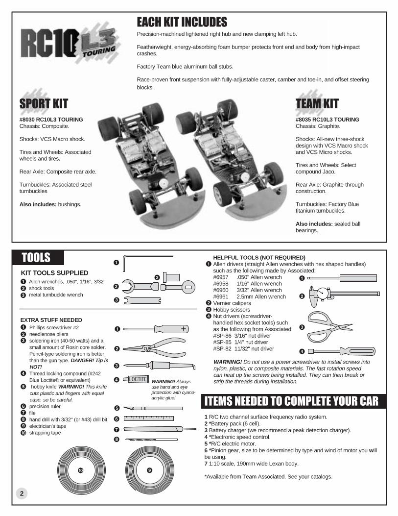
T O O L S HELPFUL TOOLS (NOT REQUIRED)Allen drivers (straight Allen wrenches with hex shaped handles) such as the following made by Associated:#6957 .050" Allen wrench#6958 1/16" Allen wrench#6960 3/32" Allen wrench#6961 2.5mm Allen wrenchVernier calipersHobby scissorsNut drivers (screwdriver-handled hex socket tools) such as the following from Associated:#SP-86 3/16" nut driver#SP-85 1/4" nut driver#SP-82 11/32" nut driver
WARNING! Do not use a power screwdriver to install screws into nylon, plastic, or composite materials. The fast rotation speed can heat up the screws being installed. They can then break or strip the threads during installation.
KIT TOOLS SUPPLIED
EXTRA STUFF NEEDEDPhillips screwdriver #2needlenose plierssoldering iron (40-50 watts) and a small amount of Rosin core solder. Pencil-type soldering iron is better than the gun type. DANGER! Tip is HOT!Thread locking compound (#242 Blue Loctite© or equivalent) hobby knife WARNING! This knife cuts plastic and fingers with equal ease, so be careful.precision ruler filehand drill with 3/32" (or #43) drill bitelectrician's tapestrapping tape
Allen wrenches, .050", 1/16", 3/32"shock toolsmetal turnbuckle wrench
WARNING! Alwaysuse hand and eye protection with cyano-acrylic glue! I T E M S N E E D E D T O C O M P L E T E Y O U R C A R
1 R/C two channel surface frequency radio system.2 *Battery pack (6 cell).3 Battery charger (we recommend a peak detection charger).4 *Electronic speed control.5 *R/C electric motor.6 *Pinion gear, size to be determined by type and wind of motor you will be using.7 1:10 scale, 190mm wide Lexan body.
*Available from Team Associated. See your catalogs.
T E A M K I T#8035 RC10L3 TOURINGChassis: Graphite.
Shocks: All-new three-shock design with VCS Macro shock and VCS Micro shocks.
Tires and Wheels: Select compound Jaco.
Rear Axle: Graphite-through construction.
Turnbuckles: Factory Blue titanium turnbuckles.
Also includes: sealed ball bearings.
S P O R T K I T#8030 RC10L3 TOURINGChassis: Composite.
Shocks: VCS Macro shock.
Tires and Wheels: Associated wheels and tires.
Rear Axle: Composite rear axle.
Turnbuckles: Associated steel turnbuckles
Also includes: bushings.
E A C H K I T I N C L U D E SPrecision-machined lightened right hub and new clamping left hub.
Featherwieght, energy-absorbing foam bumper protects front end and body from high-impactcrashes.
Factory Team blue aluminum ball stubs.
Race-proven front suspension with fully-adjustable caster, camber and toe-in, and offset steeringblocks.
shoulder down
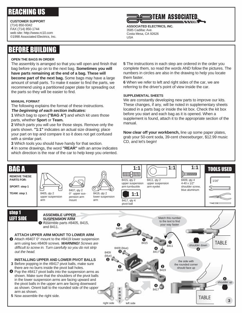
8405, qty 2upper suspension arm
8407, qty 20° upper sus-pension arm mount 8417, qty 4
pivot ball
8415, qty 2upper suspensionarm turnbuckle
8411, qty 2upper suspensionarm eyelet
s t e p 1 ASSEMBLE UPPER SUSPENSION ARM Assemble parts #8405, 8415, and 8411.
ATTACH UPPER ARM MOUNT TO LOWER ARMAttach #8407 0° mount to the #8419 lower suspension arm using two #8409 screws. WARNING! Screws are difficult to screw in. Turn carefully so you do not strip out the head.
INSTALLING UPPER AND LOWER PIVOT BALLSBefore popping in the #8417 pivot balls, make sure there are no burrs inside the pivot ball holes.Pop the #8417 pivot balls into the suspension arms as shown. Make sure that the shoulders of the pivot balls in the lower suspension arms are facing upward and the pivot balls in the upper arm are facing downward as shown. Orient ball to the rounded side of the upper arm as shown.Now assemble the right side.
L E F T S I D E
B A G AREMOVE THESE PARTS FOR:
SPORT: step 1
TEAM: step 1
1:11:1
B E F O R E B U I L D I N GOPEN THE BAGS IN ORDERThe assembly is arranged so that you will open and finish that bag before you go on to the next bag. Sometimes you will have parts remaining at the end of a bag. These will become part of the next bag. Some bags may have a large amount of small parts. To make it easier to find the parts, we recommend using a partitioned paper plate for spreading out the parts so they will be easier to find.
MANUAL FORMAT The following explains the format of these instructions. The beginning of each section indicates:1 Which bag to open ("BAG A") and which kit uses those parts, whether Sport or Team.2 Which parts you will use for those steps. Remove only the parts shown. "1:1" indicates an actual size drawing; place your part on top and compare it so it does not get confused with a similar part.3 Which tools you should have handy for that section.4 In some drawings, the word "REAR" with an arrow indicates which direction is the rear of the car to help keep you oriented.
5 The instructions in each step are ordered in the order you complete them, so read the words AND follow the pictures. The numbers in circles are also in the drawing to help you locate them faster.6 When we refer to left and right sides of the car, we are referring to the driver's point of view inside the car.
SUPPLEMENTAL SHEETSWe are constantly developing new parts to improve our kits. These changes, if any, will be noted in supplementary sheets located in a parts bag or inside the kit box. Check the kit box before you start and each bag as it is opened. When a supplement is found, attach it to the appropriate section of the manual.
Now clear off your workbench, line up some paper plates, grab your 50-cent soda, 39-cent cheeseburger, $12.99 music CD, and let's begin!
R E A C H I N G U S
ASSOCIATED ELECTRICS, INC.3585 Cadillac Ave.Costa Mesa, CA 92626USA
CUSTOMER SUPPORT(714) 850-9342FAX (714) 850-1744web site: http://www.rc10.com©1998 Associated Electrics, Inc.
3
T O O L S U S E D
Match this numberto the text to findyour way faster
84118415
8405
8407 8419
8409 (blue)
8409(blue)
8417
8417
8409, qty 44-40 x 1/2"shoulder screw,blue aluminum
1:1
1:18419, qty 2lower suspension arm
shoulder up
left sideright side
the side with the rounded corner
should face up
1/16"
3
5
FRONT

8421, qty 2offset steeringblock
8413, qty 2hinge pin
8179, qty 2spacer
8439, qty 48-32 x 5/8blue aluminum
6917, qty 24-40 x 3/8
s t e p 3L E F T S I D E
B A G AREMOVE THESE PARTS FOR:
SPORT: steps 2-3
TEAM: steps 2-3
1:1 1:11:1 T O O L S U S E D
4
8413
8413
8413
4449
4448
6299
8423
8429
8425
6299
s t e p 2
NOTE: The bottom of the chassis has the screw holes countersunk.
FILE THE CHASSISUse your file to bevel the slots on the top of the chassis so the edges won't cut through the battery cell wrap. WARNING! Graphite dust can be harmful to your health. File in a well ventilated area. Then wash the chassis with running water and dry with paper towels. Wash your hands afterward with cold water and soap. Deposit graphite filings in trash.
TAPE THE CHASSISInsulate the battery slots by wrapping the slots with electrical tape.
8413, qty 4caster shim
6299, qty 6E-clip
1:1
4448, qty 2ball endblue aluminum
1:1
4449, qty 24-40 locknut
1:1
3213, qty 2axle
8423, qty 2kingpin
8429, qty 2spring, .020
1:1
8425, qty 10kingpin shim
1:1
1:1
8403, qty 1cross brace
1/16", .050"
6917
8403
8439
8179
9
the side with the rounded corner
should face up
chassis
FRONT VIEW SHOWN
FRONT VIEW SHOWN
1:1
4187, qty 4spacer
1:1
4187
SUSPENSION ARMS TO CHASSISSlip the #8179 spacer between the suspension arm and the chassis, then bolt on with two #8439 blue aluminum screws from underneath the chassis. Do the other side.
MOUNT THE CROSS BRACEMount the #8403 cross brace to the front suspension using two #6917 button head screws.
UPPER ARM TO THE SUSPENSION MOUNTAssemble the upper arm assembly to the suspension mount as shown, using the #8413 hinge pin and #8413 shims.
FINAL FRONT SUSPENSION ASSEMBLYAssemble the #8421 steering block as shown using parts #3213, 6299, 4448, 4187, and 4449. Install the ball end into the rear hole.Place one #6299 E-clip on the bottom of the #8423 kingpin then slide the #8429 spring over.Slide the #8423 kingpin completely through the bottom of the suspension arm and up through the steering block.Place one #8425 shim on top of the #8421 steering block. Now push the upper arm over the kingpin. Place four #8425 shims over the kingpin and secure with a #6299 E-clip. Do the other side.
8425
84213213
6299
4187
SPORT ONLY: #8480.TEAM ONLY: #8474.

4335, qty 2 ea pivot socket,upper and lower
4334, qty 82-56 x 5/16
8191, qty 1T-bar, .075"
B A G BREMOVE THESE PARTS FOR:
SPORT: steps 1-3
TEAM: steps 1-3
1:11:1 T O O L S U S E D
5
s t e p 1
T-BAR ASSEMBLYSPORT ONLY: Trim the sides on the #4335 front pivot sockets in order to make room for the T-bar tweak screws. The back rear pivot stays the same.SPORT & TEAM: Assemble the #4335 T-bar sockets and #4336 pivot balls. Secure the T-bar pivot assemblies to the #8191 T-bar using eight #4334 screws as shown, installing both on the same side of the T-bar. (The side of the T-bar with the screw heads showing will be the bottom when finished.)SPORT ONLY: Install the two #4436 tweak screws as shown. Do not overtighten the screws.
4336, qty 2pivot ball
L E F T S I D E
s t e p 2R I G H T S I D E
REAR POD ASSEMBLYBolt the lower pod plate to the black #4536 left bulkhead with three #6292 screws. Bolt the aluminum #4537 motor bulkhead with two #7673 screws.Attach the lower pod plate to the T-bar with two #4526 spacers, two #6292 screws, and two #4449 locknuts. The spacer goes between the T-bar and the pod plate. The T-bar is on top.
4536, qty 1left rear bulkhead
4537, qty 1motor bulkhead
1:1
4526, qty 2T-bar spacermolded plastic
1:1
1:1
6292, qty 54-40 x 3/8steel
.050", 1/16"
4334
8191
4336
4526
6292
4536
4537
4449
4449
7260
6922
T-BAR TO CHASSISInsert the #6922 screw through the chassis hole shown and into the T-bar, and secure with a #7260 plain nut.
s t e p 3L E F T S I D E
7260, qty 14-40 nut
1:1
7673, qty 24-40 x 5/16steel
1:1
6922, qty 14-40 x 1/2
1:1
4449, qty 24-40 locknut
8320, qty 1lower pod plate
4334
4336
4335
4335
4335
4335
6292
6292
7673
7673
6292
6292
4526
4436
S P O R T K I T O N L Y
8191
S P O R T O N L Y
1:14436, qty 24-40 x 5/16Allen screw
8191
T E A M O N L Y
8475, qty 1lower pod plate
lower pod plateSPORT ONLY: #8320TEAM ONLY: #8475
Trim both sides of the two front pivot sockets
4335
4335
4335
4335
4336
4336
4334
4334

6
B A G BREMOVE THESE PARTS FOR:
SPORT: steps 4-5
TEAM: steps 4-5
T O O L S U S E D
s t e p 4
REAR CHASSIS BRACE ASSEMBLYMount the aluminum #4442 and #4441 standoffs to the #8478 rear chassis brace with two #6270 steel ball ends and one #6919 screw where shown. Mount the #8186 rear body mounts to the rear chassis brace in the holes shown and secure the mounts using two #6917 screws. (For low profile bodies, use the #8185 posts.) Tighten the #4338 collars to the posts with the #6951 set screws.
1:1
4442, qty 2dampener bracestandoff
1:1
6919, qty 34-40 x 5/16
1:1
6917, qty 34-40 x 3/8
8186, qty 2rear body mount, 5"
8482, qty 1rear chassis brace
1:1
4441, qty 1dampener center post
1/16"
8478
8186
6917
6919
6270(steel)
4442
4442
6917
8186
CHASSIS BRACE MOUNTINGInsert the #6915 screw up through the chassis then into the rear pivot part of the T-bar, and screw it into the center chassis brace standoff tube.Secure the outside aluminum standoffs to the chassis with two #7673 screws.
s t e p 5
6915
7673
1:1
6915, qty 1 4-40 x 5/8
1:1
7673, qty 24-40 x 5/16
1:1
6270, qty 24-40 ball endsteel
4441
76736270(steel)
T E A M K I T O N L Ys t e p 4
REAR CHASSIS BRACE ASSEMBLYMount the aluminum #4442 and #4441 standoffs to the #8478 rear chassis brace with three #6919 screws. Mount the #8186 rear body mounts to the rear chassis brace in the holes shown and secure the mounts using two #6917 screws. (For low profile bodies, use the #8185 posts.) Tighten the #4338 collars to the posts with the #6951 set screws. Place a small amount of Locktite on the tip of a #6917 screw. Mount the #4516 dampener post to the rear chassis brace with the #6917 screw.
S P O R T K I T O N L Y B O T H K I T S
8186
8186
44426917
4441
8482
6919
6919
6919
4516
4517
8330
4340
6917
4442
6917
1:1
4517, qty 1dampener spring
1:1
8330, qty 1dampener O-ringblack
4340, qty 1dampener washer
4516, qty 1dampener post
1:1
S P O R T O N L YT E A M O N L Y
8478, qty 1rear chassis brace
69514338
DAMPENER ASSEMBLYSlide the #4517 spring, #8330 O-ring, and #4340 washer over the #4516 post in the order shown.
69514338
4338, qty 2body postcollar
8185, qty 2rear body mount, 3"
1:1
6951, qty 2set screw
1:1
B A G BREMOVE THESE PARTS FOR:
SPORT: step 6
TEAM: step 6
T O O L S U S E D1:1
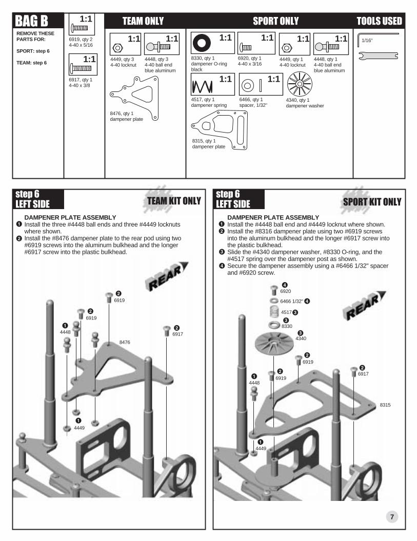
6919, qty 24-40 x 5/16
1:1
6917, qty 14-40 x 3/8
1/16"1:1
4449, qty 34-40 locknut
8476, qty 1dampener plate
1:1
T E A M K I T O N L Y S P O R T K I T O N L Y
DAMPENER PLATE ASSEMBLYInstall the three #4448 ball ends and three #4449 locknuts where shown.Install the #8476 dampener plate to the rear pod using two #6919 screws into the aluminum bulkhead and the longer #6917 screw into the plastic bulkhead.
s t e p 6L E F T S I D E
8476
6919
4448 6917
4449
6919
s t e p 6L E F T S I D E
DAMPENER PLATE ASSEMBLYInstall the #4448 ball end and #4449 locknut where shown.Install the #8316 dampener plate using two #6919 screws into the aluminum bulkhead and the longer #6917 screw into the plastic bulkhead.Slide the #4340 dampener washer, #8330 O-ring, and the #4517 spring over the dampener post as shown. Secure the dampener assembly using a #6466 1/32" spacer and #6920 screw.
4448
4449
8315
6919
69196917
4340
8330
4517
6466 1/32"
6920
7
1:1
4517, qty 1dampener spring
1:1
8330, qty 1dampener O-ringblack
4340, qty 1dampener washer
8315, qty 1dampener plate
1:1
6920, qty 14-40 x 3/16
S P O R T O N L YT E A M O N L Y
1:1
4449, qty 14-40 locknut
1:1
4448, qty 14-40 ball endblue aluminum
4448, qty 34-40 ball endblue aluminum
1:1
6466, qty 1spacer, 1/32"

B A G CREMOVE THESE PARTS FOR:
SPORT: steps 1-4
TEAM: steps 1-4
1:1
T O O L S U S E D
s t e p 1
DIFFERENTIAL ASSEMBLYFind the #4349 adjusters that have a small #1 on them, and insert them into the rear pod, hole at top. (The tuning tips section has more info on these.)TEAM KIT ONLY: Insert two #897 flanged ball bearings into the ride height adjusters as shown.SPORT KIT ONLY: Insert two #8208 metal flanged bushings into the ride height adjusters as shown.
L E F T S I D E
8
6636
6626
s t e p 3
FINAL DIFF ASSEMBLYHold the axle upright and slide the #6625 diff ring over the axle and onto the aluminum hub of the axle.Slide the #8282 spur gear over the axle and center it on the hub.Install the second #6625 diff ring as shown.SPORT KIT: Insert a #897 bearing into the end of the #8477 wheel hub shown, an #8208 flanged bushing into the other side, then slide the wheel hub over the axle.TEAM KIT: Insert a #897 bearing into each end of the #8477 wheel hub, then slide the wheel hub over the axle.Install the #8213 cone so that the smaller end is facing the wheel hub. Place the three #8213 washers over the axle so that the smaller end faces away from the cone, and secure with a #4185 locknut. We will adjust the diff after we put the wheels on.
6625
6625
8213
4185
8282
8213
DIFF GEARAdd #6636 silicone grease to the #8282 diff gear ball holes and center hole.Push the eight #6626 diff balls into the holes.
8282
SPORT KIT ONLY: #8209TEAM KIT ONLY: #4355
897, qty 41/4 x 3/8flanged bearing
4349, qty 2ride heightadjuster, #1 UP
6626, qty 81/8" diff ball
1:1
8282, qty 1diff gear81 tooth
8209, qty 1composite axle
4185, qty 18-32 locknut
1:1
8213, qty 3Belleville washer
1:1
1:1
8213, qty 1diff thrust cone
1:1
6625, qty 2diff drive ring
6636, qty 1silicone grease
s t e p 2
3/32"
8477
4349
6924, qty 14-40 x 3/8
1:1
aluminum hub
4355, qty 1graphite axle
S P O R T O N L YT E A M O N L Y
1:1
8208, qty 31/4 x 3/8flanged bushing
8477, qty 1right wheel hub
8465, qty 1left wheel hub
897
S P O R T K I T O N L Y
8978208 bushing
897bearing
8477
1:1
897, qty 11/4 x 3/8flanged bearing
S P O R T K I T O N L Y
43498208bushing

B A G DREMOVE THESE PARTS FOR:
SPORT: steps 1-4
TEAM: steps 1-4
SHOCK/ANTENNA MOUNTRemove the shock cap bushing from the #8184 shock antenna mount.Install the mount using two #6922 aluminum screws.
5407, qty 2red O-ring
6464, qty 1shock piston #1
5422, qty 130 wt silicone oil
1:1 1:1 T O O L S U S E D
s t e p 1
6464TRIM SHOCK PISTONBurrs on the #6464 shock piston interfere with smooth shock action within the shock body. To remove from tree without creating burrs, twist up, not down. Remove one #1 shock piston.Remove remaining burrs carefully with a hobby knife.
burr
wrong
right
s t e p 2
VC FOAM AND PISTONSoak the #8456 VC foam with #5422 shock oil and install it onto the #8456 VC bobbin.
s t e p 3
6469, qty 1large O-ring
6299, qty 2E-clip
1:1 1:1
6922, qty 24-40 x 1/2steel
1:1
8458, qty 1macro shock body
6460, qty 1shock shaft
8184, qty 1shock/antennamount
remove this part, then put aside
for later assembly
1:1
7230, qty 1ball cup
1/16"
6922
2
5422
O I L
Install the #6469 O-ring over the threads of the #8458 shock body.Install a #6299 E-clip on either side of a #6464 (#1) piston from step 2.Slide the assembled VC foam/bobbin over the #6460 shaft and then two #5407 red O-rings. Place a couple of drops of oil on the O-rings.Insert the assembly into the shock body and pull the shaft through firmly to seat the VC bobbin at the base of the shock bore.Screw the #7230 ball cup onto the end of the shock shaft while holding the shaft with needlenose pliers next to threads.
s t e p 4
5422O I L
6299
6299
64698458
5407
7230
9
8184
8184
8456foam
8456bobbin
6460
6464 (#1)
8456, qty 1VC foam
1:1
8456, qty 1VC bobbin
Use a piece of paper or smooth part of jaws to prevent damaging shaft.
6922
s t e p 4
INSTALLING DIFF ASSEMBLYSlide the complete rear axle assembly through the motor bulkhead until it extends through the plastic bulkhead on the other side.Install the #8465 left wheel hub onto the rear axle. Thread the #6924 screw into the hub to tighten it to the axle.
SETTING THE AXLE END PLAYMake sure there is a slight (less than 1/64" or .015" or .4mm) amount of axle end play when tightening the left hub clamping screw.
6924
REAR VIEW SHOWN
8465
assembled
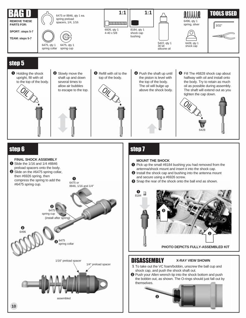
6475 or 8846, qty 1 ea.spring preloadspacers, 1/4, 1/16
FINAL SHOCK ASSEMBLYSlide the 1/16 and 1/4 #8846 preload spacers onto the body.Slide on the #6475 spring collar, then #6926 spring, then compress the spring to add the #6475 spring cup.
B A G DREMOVE THESE PARTS FOR:
SPORT: steps 5-7
TEAM: steps 5-7
6475spring collar
6475spring cup
6475, qty 1spring collar
6475, qty 1spring cup
(install after spring)
6428
s t e p 6
T O O L S U S E D
s t e p 5
6496, qty 1spring, silver
6496
3/32"
Holding the shock upright, fill with oil to the top of the body.
Slowly move the shaft up and down several times to allow air bubbles to escape to the top.
Refill with oil to the top of the body.
Push the shaft up until the piston is level with the top of the body. The oil will bulge up above the shock body.
Fill The #6828 shock cap about halfway with oil and install onto the body. Try to retain as much oil as possible during assembly. The shaft will extend out as you tighten the cap down.
5422, qty 130 wt silicone oil
6428, qty 1shock cap
10
MOUNT THE SHOCKPick up the small #8184 bushing you had removed from the antenna/shock mount and insert it into the shock cap.Install the shock cap and bushing into the antenna mount and secure using a #6926 screw.Snap the rear of the shock onto the ball end as shown.
s t e p 7
8184
PHOTO DEPICTS FULLY-ASSEMBLED KIT
6926, qty 14-40 x 5/8
1:1
8184, qty 1shock capbushing
1:1
6475 or8846, 1/16 and 1/4"
1/16" preload spacer1/4" preload spacer
D I S A S S E M B L YTo take out the VC foam/bobbin, unscrew the ball cup and shock cap, and push the shock shaft out. Push your Allen wrench tip into the shock bottom and push the bobbin out, as shown. The O-rings should just fall out by themselves.
1
X-RAY VIEW SHOWN
assembled
B A G DREMOVE THESE PARTS FOR:
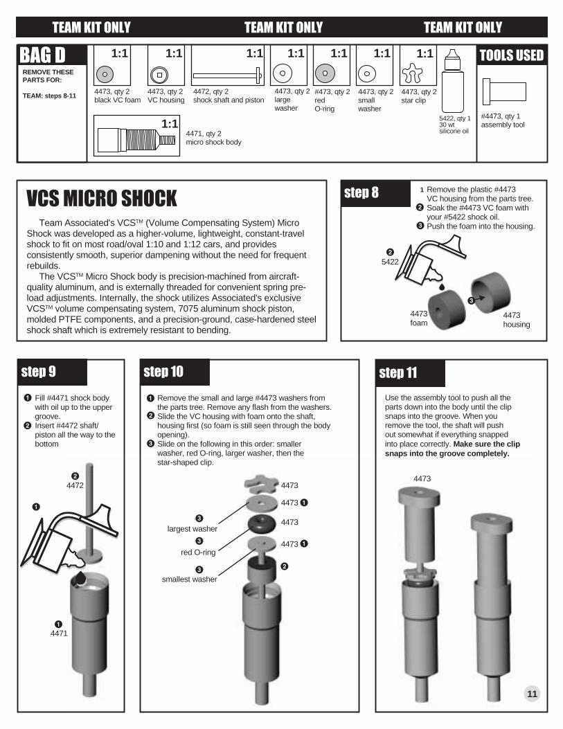
TEAM: steps 8-11
T O O L S U S E D
s t e p 8
11
4473, qty 2black VC foam
4473, qty 2VC housing
4471, qty 2micro shock body
4472, qty 2shock shaft and piston
4473, qty 2small washer
#473, qty 2redO-ring
4473, qty 2largewasher
4473, qty 2star clip
#4473, qty 1assembly tool
Remove the plastic #4473 VC housing from the parts tree.Soak the #4473 VC foam with your #5422 shock oil.Push the foam into the housing.
1
Fill #4471 shock body with oil up to the upper groove.Insert #4472 shaft/piston all the way to the bottom
Remove the small and large #4473 washers from the parts tree. Remove any flash from the washers.Slide the VC housing with foam onto the shaft, housing first (so foam is still seen through the body opening).Slide on the following in this order: smaller washer, red O-ring, larger washer, then the star-shaped clip.
smallest washer
largest washer
red O-ring
Use the assembly tool to push all the parts down into the body until the clip snaps into the groove. When you remove the tool, the shaft will push out somewhat if everything snappedinto place correctly. Make sure the clipsnaps into the groove completely.
s t e p 9 s t e p 1 0
4473
4473
4473
4473
1:1 1:1 1:1 1:1 1:1 1:1
1:1
1:1
V C S M I C R O S H O C K Team Associated's VCSTM (Volume Compensating System) Micro Shock was developed as a higher-volume, lightweight, constant-travel shock to fit on most road/oval 1:10 and 1:12 cars, and provides consistently smooth, superior dampening without the need for frequent rebuilds. The VCSTM Micro Shock body is precision-machined from aircraft-quality aluminum, and is externally threaded for convenient spring pre-load adjustments. Internally, the shock utilizes Associated's exclusive VCSTM volume compensating system, 7075 aluminum shock piston, molded PTFE components, and a precision-ground, case-hardened steel shock shaft which is extremely resistant to bending.
5422, qty 130 wt silicone oil
4473housing
4473foam
s t e p 1 1
4473
T E A M K I T O N L Y T E A M K I T O N L Y T E A M K I T O N L Y
5422
4472
4471

screw on flange first
B A G DREMOVE THESE PARTS FOR:
TEAM: steps 12-14
T O O L S U S E D
s t e p 1 2
#4474, qty 2shock shaft end
#6951, qty 2set screw
#8451, qty 2silver spring
#4473, qty 2springadjusting nut
#6274, qty 4ball cup disassembly rod
.050"
Slide the #8451 spring over the body and up against the #4473 adjusting nut.Screw the #6274 ball cup onto the #4474 shock shaft end.Tighten the #4474 shock shaft end to the shaft with the#6951 set screw.
Pop the #6274 ball cups on the ball ends of your kit.Turn the spring adjusting nut to adjust spring tension.
Remove the assembly tool and screw on the #6274 ball cup where shown.Screw the #4473 spring adjusting nut onto the shock body threads, flange first, as shown.
To remove the parts from inside the shock, first loosen the#6951 set screw of the #4474 shock shaft end (step 13), then slide off the shaft end and spring. Now carefully insert your disassembly rod into one of the rounded grooves of the star clip and pop it out.
flange on this side
turn to adjust tension
D I S A S S E M B L Ys t e p 1 4
s t e p 1 3
6274
4473
84516274
4474
6951
1
12
T E A M K I T O N L Y T E A M K I T O N L Y T E A M K I T O N L Y
body painting suggestions (body not included in kits)top: Nissan Primera from Protoformbottom: Mercedes CLK from Protoform
PHOTO DEPICTS FULLY-ASSEMBLED KIT
B O XREMOVE THESE PARTS FOR:
SPORT: steps 1-2
TEAM: steps 1-2
T O O L S U S E D
s t e p 1L E F T S I D E
1:1
6299, qty 2e-clip
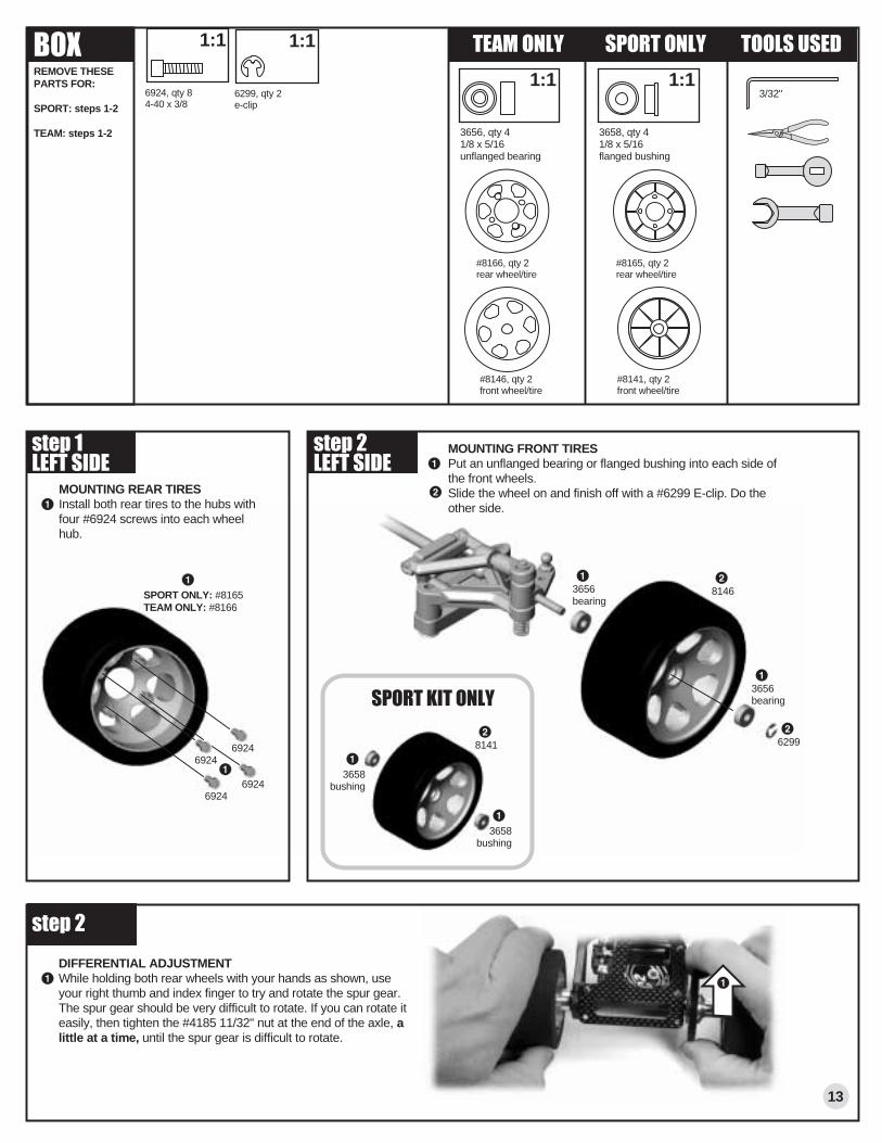
DIFFERENTIAL ADJUSTMENTWhile holding both rear wheels with your hands as shown, use your right thumb and index finger to try and rotate the spur gear. The spur gear should be very difficult to rotate. If you can rotate it easily, then tighten the #4185 11/32" nut at the end of the axle, a little at a time, until the spur gear is difficult to rotate.
s t e p 2
13
MOUNTING REAR TIRESInstall both rear tires to the hubs with four #6924 screws into each wheel hub.
1:1
6924
MOUNTING FRONT TIRESPut an unflanged bearing or flanged bushing into each side of the front wheels.Slide the wheel on and finish off with a #6299 E-clip. Do the other side.
1:16924, qty 84-40 x 3/8
#8165, qty 2rear wheel/tire
#8141, qty 2front wheel/tire
3/32"
69246924
69246299
s t e p 2L E F T S I D E
SPORT ONLY: #8165TEAM ONLY: #8166
#8166, qty 2rear wheel/tire
#8146, qty 2front wheel/tire
S P O R T O N L YT E A M O N L Y
1:1
3656, qty 4 1/8 x 5/16unflanged bearing
3658, qty 4 1/8 x 5/16flanged bushing
S P O R T K I T O N L Y
81463656bearing
3658bushing
8141
3656bearing
3658bushing
s t e p 1 for large servos,drill these two for small servos
(not recommendedfor 1:10 scale)
drill into blockperpendicular tothe slanted face
NO! Don't drill into theblock at an angle to the slanted face
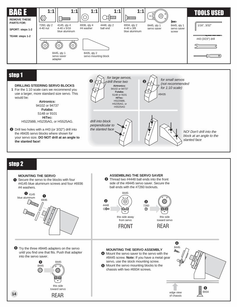
DRILLING STEERING SERVO BLOCKSFor the 1:10 scale cars we recommend you use a larger, more standard size servo. This would be:
Airtronics: 94102 or 94737
Futaba:S148 or 9101
HiTec:HS225BB, HS235AG, or HS525AG.
Drill two holes with a #43 (or 3/32") drill into the #8435 servo blocks where shown for your servo size. DO NOT drill at an angle to the slanted face!
s t e p 2
MOUNTING THE SERVOSecure the servo to the blocks with four #4145 blue aluminum screws and four #6936 #4 washers.
4145blue aluminum
6936
8445
4448
8445
8445
6934
ASSEMBLING THE SERVO SAVERThread two #4448 ball ends into the front side of the #8445 servo saver. Secure the ball ends with the #7260 locknuts.
MOUNTING THE SERVO ASSEMBLYMount the servo saver to the servo with the #8445 screw. Note: If you have a metal gear servo, use the stock mounting screw. Mount the servo mounting blocks to the chassis with two #6934 screws.
this side awayfrom servo
this sidetoward servo
8445
edge viewof chassis
F R O N T
R E A R14
Try the three #8445 adapters on the servo until you find one that fits. Push that adapter into the servo saver.
this sidetoward servo
7260
R E A R
1Airtronics:
94102 or 94737Futaba:
S148 or 9101HiTec:
HS225BB, HS235AG, or
HS525AG
B A G EREMOVE THESE PARTS FOR:
SPORT: steps 1-2
TEAM: steps 1-2
8435, qty 2servo mounting block
T O O L S U S E D
4145, qty 44-40 x 5/16blue aluminum
1:1
6936, qty 4#4 washer
1:1
8445, qty 1servo saver
8445, qty 1servo saverscrew
8445, qty 1servo saveradapter
4448, qty 2ball end
1:1
6934, qty 24-40 x 3/8blue aluminum
1:1
7260, qty 24-40 nut
1:1
1/16", 3/32"
#43 (3/23") drill
#8435

B A G EREMOVE THESE PARTS FOR:
SPORT: steps 3-4
TEAM: steps 3-4
T O O L S U S E D
s t e p 3
STEERING LINKAGEInstall the plastic #6274 ball cups onto the #1405 titanium steering turnbuckles. Match the length of the turnbuckles to the actual size picture below.Snap one ball cup onto the ball end on the servo saver. Snap the opposite end on as shown. Install both turnbuckles.When you are adjusting your turnbuckles, always make sure that the servo saver is pointing straight down.
1:1
s t e p 4
FRONT BUMPERBolt the #8303 front bumper to the front of the chassis with two #6942 blue screws from underneath and two #3438 locknuts on top.
FRONT BODY MOUNT POSTSTighten the #8304 body posts to the bumper with two #6942 blue screws from underneath.Cut and trim the #8305 foam bumper with a sanding block to fit the body of your choice and slide it over the two body mounts.Add #6332 body clips to the front posts and the rear.
6274 6274
2.40"
6274, qty 4ball cup
15
6332, qty 4body clip
1:1
6942, qty 48-32 x 1/2blue aluminum
8304, qty 2front body post
1:1
8303, qty 1front bumper
1:1
3438, qty 28-32 locknut
3
8305, qty 1foam bumper
8303
6942
6942
3438
3438
6942
8304
8304
6942
6332
6332
8305
SPORT ONLY: #8438 steelTEAM ONLY: #1405 titanium
8438, qty 2steel steering turnbuckle
1:1
1405, qty 2blue titanium steering turnbuckle
1:1
S P O R T O N L Y
T E A M O N L Y
- B A T T E R Y +
+ B A T T E R Y -
- B A T T E R Y +
16
s t e p 5
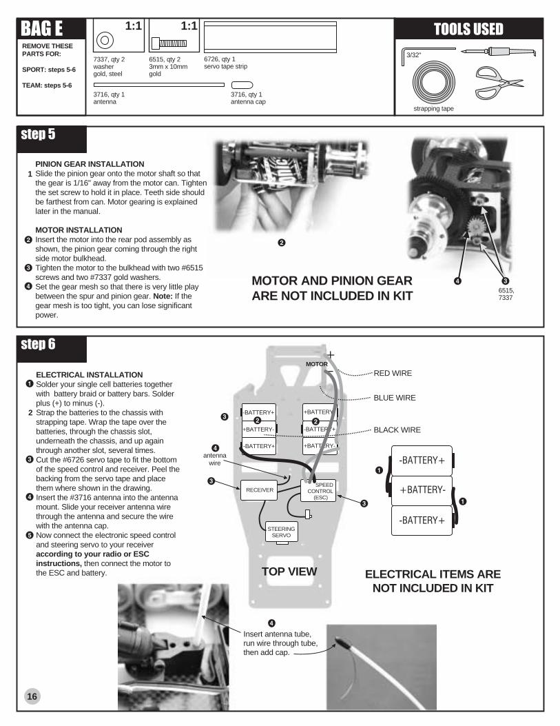
PINION GEAR INSTALLATIONSlide the pinion gear onto the motor shaft so that the gear is 1/16" away from the motor can. Tighten the set screw to hold it in place. Teeth side should be farthest from can. Motor gearing is explained later in the manual.
MOTOR INSTALLATIONInsert the motor into the rear pod assembly as shown, the pinion gear coming through the right side motor bulkhead.Tighten the motor to the bulkhead with two #6515 screws and two #7337 gold washers.Set the gear mesh so that there is very little play between the spur and pinion gear. Note: If the gear mesh is too tight, you can lose significant power.
B A G EREMOVE THESE PARTS FOR:
SPORT: steps 5-6
TEAM: steps 5-6
T O O L S U S E D
7337, qty 2washergold, steel
1:1
MOTOR AND PINION GEARARE NOT INCLUDED IN KIT
6515, qty 23mm x 10mmgold
1:1
s t e p 6
STEERINGSERVO
-BATTERY+
+BATTERY-
-BATTERY+
+BATTERY-
-BATTERY+
+BATTERY-
+_
ELECTRICAL INSTALLATIONSolder your single cell batteries together with battery braid or battery bars. Solder plus (+) to minus (-).Strap the batteries to the chassis with strapping tape. Wrap the tape over the batteries, through the chassis slot, underneath the chassis, and up again through another slot, several times.Cut the #6726 servo tape to fit the bottom of the speed control and receiver. Peel the backing from the servo tape and place them where shown in the drawing.Insert the #3716 antenna into the antenna mount. Slide your receiver antenna wire through the antenna and secure the wire with the antenna cap.Now connect the electronic speed control and steering servo to your receiver according to your radio or ESC instructions, then connect the motor to the ESC and battery. ELECTRICAL ITEMS ARE
NOT INCLUDED IN KIT
3716, qty 1antenna
3716, qty 1antenna cap
strapping tape
RECEIVER
6726, qty 1servo tape strip
antennawire
1
RED WIRE
BLUE WIRE
BLACK WIRE
3/32"
TOP VIEW
MOTOR
2
Insert antenna tube,run wire through tube,then add cap.
SPEEDCONTROL
(ESC)
6515,7337

FINAL ADJUSTMENTS
TIRE DIAMETER ADJUSTMENTIf you change tire diameter you can affect yourgearing. You can calculate any gearing adjustmentsby using the following formulas.
Old Pinion Factor Results New PinionGear Gear 18 X 1.105 = 19.89 = 20 (round to nearest
whole number)
Old NewTire Tire FactorDia. Dia.( 2.1" ÷÷÷÷÷ 1.9" ) = 1.105
MAKE THESE ADJUSTMENTS BEFORE RACING
SETTING THE TWEAKWe set the “tweak” after everything except the
body is installed on the car, including batteries, mo-tor, speed control, and all the radio equipment.
WHAT IS TWEAK? Ideally, the left wheelshould be pushing down on the ground with ex-actly the same force as the right wheel. If this isnot happening, the car is TWEAKED (or twisted).This can cause the car to spin out easily underacceleration. It will also cause the car to oversteerin one direction and understeer in the opposite di-rection.
CHECKING THE TWEAK.1 Measure the front chassis width. Use half of thismeasurement to find the centerline of the chassis.2 Scratch a mark at the centerline at the front ofthe chassis with your hobby knife as in photo.3 To tweak the car, place the tip of a hobby knifeon the center mark as shown.
4 Lift the front of the car slowly. For a neutral han-dling car, we want both front tires to leave theground at the same time. If one tire leaves theground before the other one, the car is tweaked.
ADJUSTING THE TWEAK, TEAM KIT. Afterchecking the tweak, tighten the spring adjustingnut (page 12, step 14) 1/2 turn on the tire side thatleft the ground first. Now loosen the opposite shockspring adjusting nut the same amount. Now recheckthe tweak. Continue to make these adjustments untilyou achieve the amount of tweak desired.
ADJUSTING THE TWEAK, SPORT KIT. Afterchecking the tweak, loosen the T-bar tweak screw(page 5, step 1) 1/8 of a turn on the tire side thatleft the ground first. Now tighten the opposite tweakscrew (the one that left the ground last) the sameamount. Now recheck the tweak. Continue to makethese adjustments until you achieve the amount oftweak desired.
PAINTING THE BODY1 While the body is still clear, mark and cut out theholes for the body mounts and antenna tube.2 Clean the body and wing thoroughly before paint-ing with warm water and a mild dish soap.
3 Mask the inside of the body according to yourpaint scheme, using automotive masking tape forthe best results. Take the time to press down alledges of the tape. Mask off the holes you cut withtape on the outside of the body.
4 Spray the body and wing, applying the paint inthin coats and letting it dry between coats. Werecommend Pactra paints.
RADIO ADJUSTMENTSCharge the transmitter batteries if they are NiCads.(See your radio manual for instructions.) Nextcharge your battery pack according to the instruc-tions included with your battery charger or batterypack. Make sure all the ESC connections are ac-cording to the appropriate manuals. Now use thefollowing steps to make the final adjustments onyour car.1 Turn the transmitter switch ON2 Make sure the motor is unplugged or unsoldered.3 Plug in or solder in your battery pack.4 Turn the car switch to the ON position. (This isnormally attached to the ESC.)5 Move the steering control on the transmitter tothe right. Do the wheels steer to the right? If not,you must reverse the steering servo direction on
your transmitter (see radio manual).6 After you have the wheels steering in the correctdirection, remove your hand from the steering con-trol on the transmitter. Now look at the servo hornmounted on the servo. Is it pointing straight down?If not, adjust its position with the steering trim con-trol on the transmitter, or move its position on theservo.7 Now look at your front wheels. Are they pointedstraight ahead in relation to the center line of thechassis? If not, first check the alignment of theservo saver in relation to the wheels. Do they nowpoint straight ahead? If not, use the steering tie-rod turnbuckles to adjust each wheel so that it ispointed straight ahead.8 Adjust the ESC (electronic speed control) ac-cording to the speed control manufacturer’s instruc-
tions. Note: Some manufacturers have the motorconnected during adjustment and some do not. Nowturn the car ON/OFF switch OFF.9 Plug in or solder in your motor. Place your car ona block or car stand so that the rear wheels cannottouch anything. Turn the car switch back ON. Checkthe ESC operation and settings. After you have setand checked the speed control, turn the car switchOFF.10 The transmitter switch must always be the FIRSTSWITCH TURNED ON and THE LAST SWITCHTURNED OFF.
CONGRATULATIONS! YOUR CAR IS NOWREADY TO RUN!
MOTOR GEARINGTo get the most from your motor proper gearing isimportant. The gear ratios listed in the chart beloware recommended starting gear ratios. Ratios canvary from track to track but you should not changethe pinion size more than one tooth from the rec-ommended ratio.
CAUTION! Increasing the pinion size by morethan one tooth can damage your motor from ex-cess heat.
MOTOR PINION SPUR24° ROAR stock motor 26 81DS Spec motor 25 8136° stock motor 24 8114 turn modified motor 21 8413 turn modified motor 20 8412 turn modified motor 19 8411 turn motor 18 84
17
Here are some guidelines to optimize tweak: Both tires leave the ground at the same time:
neutral, easy-to-drive steering. Left front tire leaves the ground first: less steer-
ing (understeer). Right front tire leaves the ground first: more steer-
ing (oversteer).
18
BATTERY CHARGING &DISCHARGING
The battery packs used for R/C cars are six-cell, sub-C, rechargeable type found in any hobbyshop.
CHARGING. Proper battery charging and dis-charging is important to maintain the performanceand life of your battery pack.
Associated recommends the use of a goodquality automatic peak detection type charger. Peakdetection chargers will automatically sense whenthe battery pack is fully charged and shut off, thuslessening the chance of damage due to over charg-ing. Timer chargers are not recommended becausea mistake can be made, thus damaging the bat-tery pack.
DISCHARGING. To maintain performancefrom your battery packs, it is recommended youcompletely discharge them between charges. Thereare several inexpensive discharges available at yourhobby shop. Associated recommends the light bulbtype discharger that is popular with the racers. Fol-low the discharging instructions supplied with yourdischarger for best battery performance.
TUNING & SETUP TIPS
MAINTENANCE FOLLOW THESE STEPS TO KEEP YOUR CAR IN SHAPE FOR RACING
THESE STEPS PREPARE YOUR CAR FOR MAXIMUM PERFORMANCE
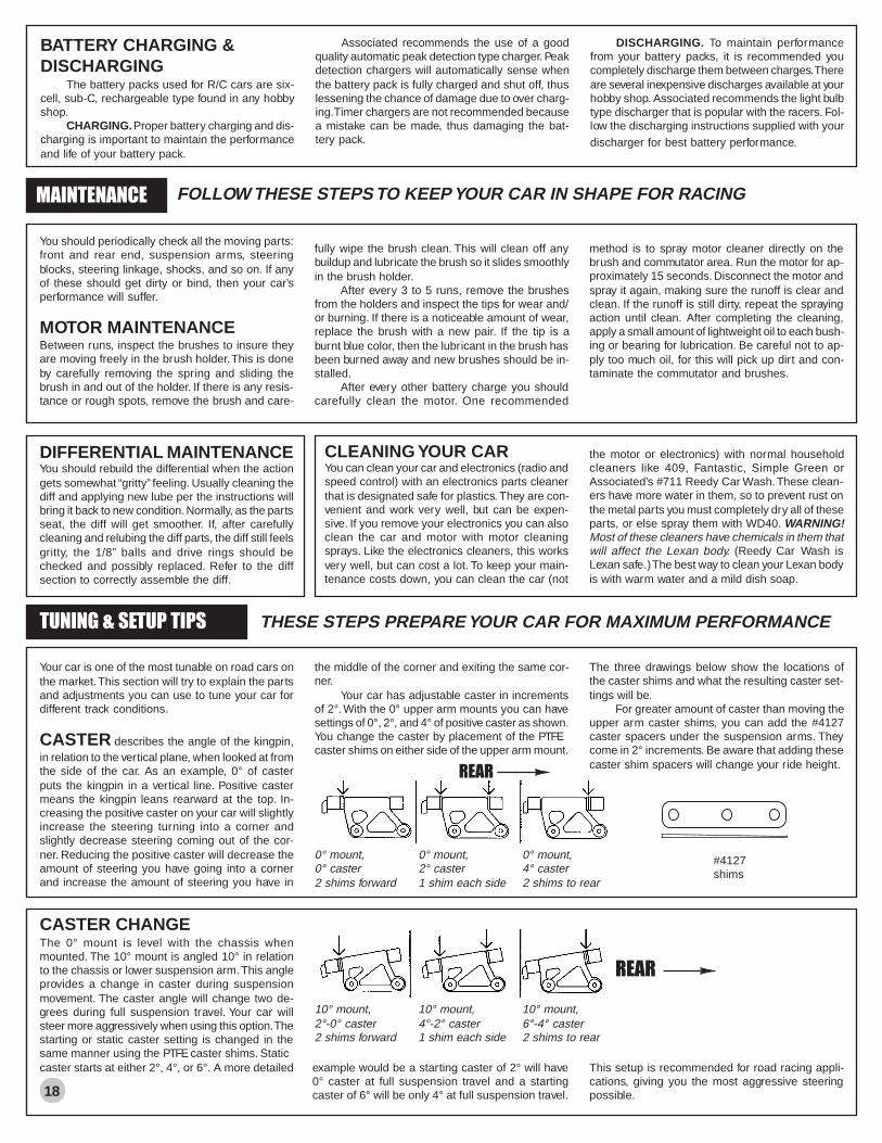
0° mount, 0° mount, 0° mount,0° caster 2° caster 4° caster2 shims forward 1 shim each side 2 shims to rear
You should periodically check all the moving parts:front and rear end, suspension arms, steeringblocks, steering linkage, shocks, and so on. If anyof these should get dirty or bind, then your car’sperformance will suffer.
MOTOR MAINTENANCEBetween runs, inspect the brushes to insure theyare moving freely in the brush holder. This is doneby carefully removing the spring and sliding thebrush in and out of the holder. If there is any resis-tance or rough spots, remove the brush and care-
fully wipe the brush clean. This will clean off anybuildup and lubricate the brush so it slides smoothlyin the brush holder.
After every 3 to 5 runs, remove the brushesfrom the holders and inspect the tips for wear and/or burning. If there is a noticeable amount of wear,replace the brush with a new pair. If the tip is aburnt blue color, then the lubricant in the brush hasbeen burned away and new brushes should be in-stalled.
After every other battery charge you shouldcarefully clean the motor. One recommended
method is to spray motor cleaner directly on thebrush and commutator area. Run the motor for ap-proximately 15 seconds. Disconnect the motor andspray it again, making sure the runoff is clear andclean. If the runoff is still dirty, repeat the sprayingaction until clean. After completing the cleaning,apply a small amount of lightweight oil to each bush-ing or bearing for lubrication. Be careful not to ap-ply too much oil, for this will pick up dirt and con-taminate the commutator and brushes.
DIFFERENTIAL MAINTENANCEYou should rebuild the differential when the actiongets somewhat “gritty” feeling. Usually cleaning thediff and applying new lube per the instructions willbring it back to new condition. Normally, as the partsseat, the diff will get smoother. If, after carefullycleaning and relubing the diff parts, the diff still feelsgritty, the 1/8” balls and drive rings should bechecked and possibly replaced. Refer to the diffsection to correctly assemble the diff.
CLEANING YOUR CARYou can clean your car and electronics (radio andspeed control) with an electronics parts cleanerthat is designated safe for plastics. They are con-venient and work very well, but can be expen-sive. If you remove your electronics you can alsoclean the car and motor with motor cleaningsprays. Like the electronics cleaners, this worksvery well, but can cost a lot. To keep your main-tenance costs down, you can clean the car (not
the motor or electronics) with normal householdcleaners like 409, Fantastic, Simple Green orAssociated’s #711 Reedy Car Wash. These clean-ers have more water in them, so to prevent rust onthe metal parts you must completely dry all of theseparts, or else spray them with WD40. WARNING!Most of these cleaners have chemicals in them thatwill affect the Lexan body. (Reedy Car Wash isLexan safe.) The best way to clean your Lexan bodyis with warm water and a mild dish soap.
Your car is one of the most tunable on road cars onthe market. This section will try to explain the partsand adjustments you can use to tune your car fordifferent track conditions.
CASTER describes the angle of the kingpin,in relation to the vertical plane, when looked at fromthe side of the car. As an example, 0° of casterputs the kingpin in a vertical line. Positive castermeans the kingpin leans rearward at the top. In-creasing the positive caster on your car will slightlyincrease the steering turning into a corner andslightly decrease steering coming out of the cor-ner. Reducing the positive caster will decrease theamount of steering you have going into a cornerand increase the amount of steering you have in
the middle of the corner and exiting the same cor-ner.
Your car has adjustable caster in incrementsof 2°. With the 0° upper arm mounts you can havesettings of 0°, 2°, and 4° of positive caster as shown.You change the caster by placement of the PTFEcaster shims on either side of the upper arm mount.
REAR
The three drawings below show the locations ofthe caster shims and what the resulting caster set-tings will be.
For greater amount of caster than moving theupper arm caster shims, you can add the #4127caster spacers under the suspension arms. Theycome in 2° increments. Be aware that adding thesecaster shim spacers will change your ride height.
#4127shims
CASTER CHANGEThe 0° mount is level with the chassis whenmounted. The 10° mount is angled 10° in relationto the chassis or lower suspension arm. This angleprovides a change in caster during suspensionmovement. The caster angle will change two de-grees during full suspension travel. Your car willsteer more aggressively when using this option. Thestarting or static caster setting is changed in thesame manner using the PTFE caster shims. Staticcaster starts at either 2°, 4°, or 6°. A more detailed example would be a starting caster of 2° will have
0° caster at full suspension travel and a startingcaster of 6° will be only 4° at full suspension travel.
REAR
10° mount, 10° mount, 10° mount,2°-0° caster 4°-2° caster 6°-4° caster2 shims forward 1 shim each side 2 shims to rear
This setup is recommended for road racing appli-cations, giving you the most aggressive steeringpossible.

FRONT SUSPENSION SPRINGSare available in various wire sizes as listed below.Changing springs will increase or decrease steer-ing. In general a softer spring (smaller wire diam-eter) will add steering and a harder spring (largerwire diameter) will decrease steering. Oval racingwill normally require a harder spring than roadcourse racing. The #8015 L2 kit includes #8427springs. The #8416 L2O kit includes #8429 springs.
Part Number Wire Size#8433 (.024") Harder (less steering)#8431 (.022")#8429 (kit std.) (.020")#8427 (.018") Softer (more steering)
19
CAMBER is a word describing the angle atwhich the tire and wheel rides relative to the groundwhen looked at from the front or back. This is oneof the most important adjustments on the car. Nega-tive camber means that the tire leans inward at thetop, putting it closer to the centerline of the carthan the bottom of the tire. Positive camber meansjust the opposite, the top of the tire is further awayfrom the centerline of the car than the bottom ofthe tire.
TOE-IN AND TOE-OUT is a beneficialadjustment and has a fairly significant effect on thecar. Toe-in will help stabilize your car and it alsoremoves a small amount of turn in steering. Toe-out will allow the car to turn in to a corner quickerbut will reduce stability exiting the corner. Both toe-in and toe-out will scrub speed so try to use aslittle, of either, as possible. You adjust the toe-in ortoe-out by adjusting the length of the steering tie-rod turnbuckles.
Excessive negative camber willdecrease traction but increase sta-bility. Positive camber will do thesame. We suggest a starting settingof 2° of negative camber. Try to useat least 1 to 2° negative camber atall times and make adjustments tokeep your tires wearing flat. This canbe adjusted by turning the upper armturnbuckles in the appropriate direc-tion.
REAR AXLE HEIGHTADJUSTERSYour car comes with four sets of rear axle heightadjuster inserts. These inserts allow you to raiseor lower the height of the back of the car withoutchanging tire diameters. Even though there are onlyfour offsets, three can be rotated 180° for a total ofseven different axle heights as shown.
The #4-up position allows you to use the maximum diameter tire and the #4-down position requires you touse the minimum tire diameter. This adjustment allows you to get more useful life from a set of tires byadjusting axle height as tire diameter decreases. You can also adjust the overall height of your car for highor low traction conditions.
#1-UP #2-UP #3 #2-DOWN #1-DOWN#4-UP
4
4
#4-DOWN
T-BAR FLEXLook at the back end of the of the T-bar at the "T" shaped section. You willsee there are three holes which can be used to attach the T-bar to the lowerrear pod plate. You have assembled your car using only the two outermostholes. This setup will make the rear suspension very active (soft) front-to-rear. Your car will have more rear traction and will accelerate through bumpsbetter than if you were using all three attachment holes. Try using all threeattachment holes only when racing on smooth, high traction conditions.
SAVE THIS BOOKLET!More than an instruction manual, its also a handy
pictorial supplement to Team Associated’s RC10L cata-log.
Refer to this manual for part numbers and descrip-tion when ordering parts or explaining problems forcustomer service calls.
MORE AGGRESSIVE STEERINGIf the steering of your car is not aggressive enough for you, replace the standardsteering block and axle with the optional #8441 steering block and #8443 axle.The #8443 axle requires #6902 bearings.
STANDARD OPTIONAL IN-LINE
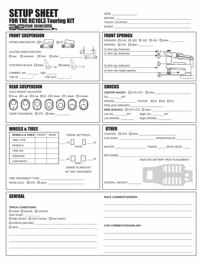
SETUP SHEETFOR THE RC10L3 Touring KIT
FRONT SUSPENSION FRONT SPRINGS
REAR SUSPENSION SHOCKS
WHEELS & TIRES
GENERAL
UPPER ARM MOUNT: 0° 10°
CASTER SHIM POSITION:
rear centered front other ________________
STEERING BLOCK: inline trailing
CAMBER, left ________ right _______
TOE-IN: _________° TOE-OUT: _________°
SPRINGS: .018 .020 .022 .024 other __________
KINGPIN: STD other __________
1) shim qty, thickness:
2) shim qty, thickness:
3) shim qty, thickness:
4) front ride height spacers:
AXLE HEIGHT ADJUSTER:
4-up 1-up 2-up #3 2-down 1-down 4-down
T-BAR THICKNESS: STD other __________
CENTER SHOCK: STD VCS other ________________________
OIL: ________WT
SPRING: ______________ PISTON: #1 #2 #3
PRELOAD SPACERS: ______________________
SIDE SHOCKS: STD VCS other ___________________________
Left OIL: ________WT Right OIL: ________WT
Left SPRING: _________ Right SPRING: _________
WHEELS & TIRES FRONT REAR
TIRE TYPE
WHEELS
TIRE DIA
STAGGER
CAR WIDTH
TIRE TREATMENT TYPE: ______________________________
REAR AXLE: STD other _________________________
TWEAK SETTINGS:
____ oz. ____ oz.
____ oz. ____ oz.
(front)
(rear)
SHADE IN AMOUNT
OF TIRE TREATMENT
OTHERCHASSIS: STD other _________________________
CAR BODY: ________________________ WING/SPOILER: ___________
MOTOR: _____________________ PINION: _____ SPUR GEAR: _____
BATTERIES: _________________________________________________
INDICATE BATTERY PACK PLACEMENT:
TRACK CONDITIONS: carpet asphalt concrete
track length: ___________ high traction med. traction low traction
artificial (describe): __________________________________________
other: _____________________________________________________
____________________________________________________________
____________________________________________________________
____________________________________________________________
RACE COMMENTS/FINISH:
____________________________________________________________
____________________________________________________________
____________________________________________________________
CAR COMMENTS/HANDLING:
____________________________________________________________
____________________________________________________________
____________________________________________________________
____________________________________________________________
DATE: _________________
DRIVER: ____________________________________________________
TRACK LOCATION: ____________________________________________
EVENT: _____________________________________________________
OVERALL WEIGHT: _________