early microwave magnetrons - educypediaeducypedia.karadimov.info/library/p_tubes.pdfthe x-band...
TRANSCRIPT
Early microwave magnetrons
The trajectory of electrons, moving under the effect of an electrostatic field, is affected bysuperimposed magnetic fields. The combined effect of electric and magnetic field on electrons hadbeen exploited in a variety of unconventional vacuum tubes, commonly referred to as ‘magnetrons’ bytheir designers.
Tyne gives several examples of early experiments on tubes where magnetic fields generated bysolenoids control electron flow. De Forest and Von Lieben patented some kinds of such electrondevices and Moorhead sold the A-P solenoid tube for a while.
The first description of the static characteristics of a device called magnetron was described by A. W.Hull in 1921. The tube had a linear filament in a coaxial cylindrical plate. The plate cylinder wassurrounded by a winding, used to generate a magnetic field. The radial electric field and thesuperimposed magnetic field forced electrons to follow circular orbits before reaching anode. If themagnetic field was raised, the radius of the orbits became smaller and smaller until electrons could notreach the plate, so causing a cut-off condition in the anode current. Hull also noted that just on theborder between conduction and cut-off, adding a resonant tank circuit, the tube could sustain self-oscillations.
Split anode magnetron designs had been approached since 1924, in order to reach more stableoscillations at higher frequencies. In this case, the LC resonant circuit was placed between the twoanodes. From 1934 to 1935 K. Posthumus at Philips developed a four segment magnetron; he also left atheoretic treatment of the rotating electron clouds, which gave the relations between the tube geometry,as the number of anodes, and the intensities of electrical and magnetic fields. In 1936, Cleeton andWilliams reached the upper frequency of 47 GHz with a split anode structure. Multi-cavity devices,forerunner of the high power magnetrons in use since WWII, had been proposed by Samuel of the BellTelephone in 1934. Multi-cavity magnetrons were subsequently developed in Russia and in England.
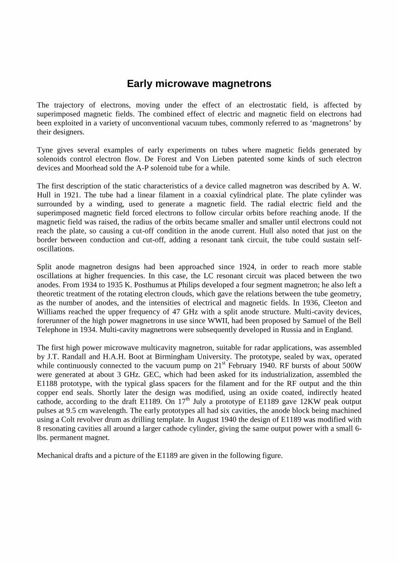
The first high power microwave multicavity magnetron, suitable for radar applications, was assembledby J.T. Randall and H.A.H. Boot at Birmingham University. The prototype, sealed by wax, operatedwhile continuously connected to the vacuum pump on 21st February 1940. RF bursts of about 500Wwere generated at about 3 GHz. GEC, which had been asked for its industrialization, assembled theE1188 prototype, with the typical glass spacers for the filament and for the RF output and the thincopper end seals. Shortly later the design was modified, using an oxide coated, indirectly heatedcathode, according to the draft E1189. On 17th July a prototype of E1189 gave 12KW peak outputpulses at 9.5 cm wavelength. The early prototypes all had six cavities, the anode block being machinedusing a Colt revolver drum as drilling template. In August 1940 the design of E1189 was modified with8 resonating cavities all around a larger cathode cylinder, giving the same output power with a small 6-lbs. permanent magnet.
Mechanical drafts and a picture of the E1189 are given in the following figure.

Fig. 1 - Left, original drafts of the E1189, the first S-band power magnetron produced by GEC. Right, a picture of theE1189 brought to North America by the Tizard mission.
One of the eight cavities E1189, the sample No. 12, was brought to the North America by the Tizardmission. Its design details were transferred to Western Electric, to Raytheon and to the Radiation Lab atMIT, in U.S., and to R.E.L. in Canada. REL was the radar-manufacturing arm of the Canadian NationalResearch Council. The sample was X-rayed and eventually left in Canada. In U.S. the RadiationLaboratory at MIT controlled the development of new radar equipment and components, includingmagnetrons. The development also continued in England, pushed by military. At the very beginningmagnetrons operated well beyond the limits of conventional electron tubes, as microwave high-powerpulse generators, but evidenced many troubles. Its operation was quite critical and frequency spectrumgenerated was influenced by unwanted modes of operation. The glass spacers and the thin coppersealing plates were delicate: many magnetrons were damaged by improper handling when attemptingto replace them in the field.
The strapping technique, connecting the cavities according to some schemes, prevented modes ofoscillation different from the pi fundamental one. Strapped magnetrons were soon available, capable ofgenerating clean pulses of several tens to hundreds kilowatts. The close co-operation amongmanufacturers, research laboratories and users of the three countries, Great Britain, U.S. and Canada,resulted in a very fast improvement of the early magnetron types, with everyday introduction of highperformance devices for every application and, virtually, for every new radar equipment.
In the next pages some of British and U.S. early S-band pulsed magnetrons are shown. Their lookclosely recalls the E1189 prototype. U.S. magnetrons evolved with the addition of mounting bracketsand of a rugged glass boot over the filament connections.

Early British S-band magnetron tubes
Fig. 2 – CV64 was the first echelon strapped magnetron, 40KW-pulse power at 3300MHz. CV186 was very similar, 35KWat 3320MHz, for use in Lancaster bombers turret gun laying radar system. CV1479 delivers 450KW pulses at 3045MHz.

US early S-band magnetrons
Fig. 3 - Some of the early U.S. S-band magnetrons. Western Electric 706A to 706C were fixed frequency cavity magnetronsinspired to the E1189 brought by the Tizard mission; shortly later they were replaced by the 706AY to 706GY version,capable of 200KW output pulses. WE 714AY gave 125KW pulses. Raytheon 2J27, capable of 265KW output pulses;although retaining the same basic structure of other similar magnetrons, its design included several improvements, such asthe glass boot to protect the filament seals and the thick mounting flange.

The X-band evolution
Once the radar sets based upon S-band magnetrons had become operative, British and U.S. researchesmoved to the next border: the development of multicavity magnetron capable of operation in the X-band region. In this band a better resolution was expected, the radar sets being compact enough to beeasily installed even in small combat airplanes, as night fighters.
The British approach approximately retained the overall dimensions of S-band magnetrons, whileincreasing the number of cavities to operate with acceptable magnetic flux densities. A large number ofcavities however resulted in a random operation, due to the increasing difficulty to avoid unwantedmodes of oscillation. At the end, a 12 slot anode was selected as best compromise betweenperformances and production easiness, being possible to accurately milling the slots with available gearcutting machines. The magnetron was approved as CV108. It looked very similar to the S-band CV64,with the exception of the output probe: a glass encased antenna, which had to be inserted into awaveguide piece.
In U.S., Western Electric followed a different design approach, scaling-down the dimensions of S-bandmagnetrons. U.S. advanced manufacturing processes made possible to form precise anode blocks in asingle operation, starting from a cylinder of oxygen-free copper. Western Electric developed its 725A,a double ring strapped X-.band magnetron, which soon became the most popular magnetron ever madeand the reference for many new design. Capable of delivering about 60KW peak power at 9375MHz,725A had a glass boot on the filament seals and a rugged flange to be easily handled even in fieldservice operations. Two figures give an idea of its success: some 89.480 units 725A were deliveredduring WWII to British Empire under the Lend-Lease Law and in the mid 950s, the same magnetroncould be bought on the surplus market for as little as 4,50 USD, versus 25,00 USD asked for a 2K25klystron.
The structure of the 725A was copied in several designs, both in U.S. and in Great Britain. 730A was a725A with a cathode bi-pin base and the waveguide flange moved to the top. 2J21 was interchangeablewith 725A and 2J48, 2J49, 2J50 from Raytheon just differed from it for their tuning frequency. BritishBTH designed the CV208, which was a 725A repackaged to be interchangeable with CV108.
Some pictures of X-band early magnetrons are given in the following page.

X-band Magnetrons
Fig. 4 – Some pictures of the early X-band pulsed magnetrons, all derived from the 725A. Top, the British CV208, with itsglass encased probe to be inserted in the waveguide adapting section. CV208 had the same shape of CV108. 730A and 2J49were U.S. variants of the 725A.

Other magnetron devices
Multicavity pulsed magnetrons became by far the most used devices in radar transmitters. But thedevelopment of this kind of velocity modulated tubes soon made available different magnetron devicesfor other applications.
CW multicavity magnetrons
These tubes were introduced for RF heating purpose. The most important applications were indiathermy electro-medical equipment and in microwave ovens for food heating/cooking. The principleof CW magnetrons is not different from their pulsed equivalent, but for operating parameters. Anodevoltage must be limited to a safe value, within the anode dissipation capability, and the magnetic fieldshould be accordingly low.
Fig. 5 - Telefunken MG8-200 delivers 200W at 3.3GHz. It is intended for diathermy electromedical equipment.

Split-anode magnetrons, 5J29
There are some very odd devices, designed for VHF/UHF military jammers, based upon the long timeknown split-anode architecture. Two fluid cooled heavy copper anodes were connected to a tunedtransmission line, to generate about 150 W at frequencies from some 150 to about 900MHz.
Fig. 6 - 5J29 was the first of three split-anode magnetrons designed by General Electric for high-frequency jammers. Thetwo anode copper blocks are internally connected by a short copper tubing which acts as shorting termination of the externaltuning line, also granting inside the circulation of the cooling fluid.

5J30, Split-anode Magnetron
Fig. 7 - General Electric 5J30, split anode magnetron. Each anode block is fluid cooled through coaxial copper tubing. Thetwo blocks are insulated from each other, the resonant line being shorted by a tuning stub on the side opposite to themagnetron. Thoriated tungsten filamentary cathode with shielding rings at each end and small shielding vanes along thefilament axis.

5J32 Split-anode Magnetron
Fig. 8 - The GE variant 5J32, which differs from the 5J30 for having double-ended connections to the anode blocks.

X-band minimagnetron, CV2380
Fig. 9 – This unusual mini-magnetron can deliver about 100mW pulses at 9400MHz. It should be mounted in a specialwaveguide resonator, with a 2450 Oersted magnetic field.