earth moving machinery-rubber tyred machines …...ais-144 1/19 earth moving machinery-rubber tyred...
TRANSCRIPT
AIS-144
I
AUTOMOTIVE INDUSTRY STANDARD
Earth Moving Machinery-Rubber
Tyred Machines-Steering Requirements
PRINTED BY
THE AUTOMOTIVE RESEARCH ASSOCIATION OF INDIA
P.B. NO. 832, PUNE 411 004
ON BEHALF OF
AUTOMOTIVE INDUSTRY STANDARDS COMMITTEE
UNDER
CENTRAL MOTOR VEHICLE RULES – TECHNICAL STANDING COMMITTEE
SET-UP BY
MINISTRY OF ROAD TRANSPORT and HIGHWAYS
(DEPARTMENT OF ROAD TRANSPORT and HIGHWAYS)
GOVERNMENT OF INDIA
March 2018

AIS-144
II
Status chart of the Standard to be used by the purchaser for updating the record
Sr. No. Corrigenda. Amendment Revision Date Remark Misc.
General remarks:

AIS-144
III
INTRODUCTION
The Government of India felt the need for a permanent agency to expedite the
publication of standards and development of test facilities in parallel when the
work on the preparation of the standards is going on, as the development of
improved safety critical parts can be undertaken only after the publication of the
standard and commissioning of test facilities. To this end, the erstwhile Ministry
of Surface Transport (MoST) has constituted a permanent Automotive Industry
Standards Committee (AISC) vide order No. RT-11028/11/97-MVL dated
September 15, 1997. The standards prepared by AISC will be approved by the
permanent CMVR Technical Standing Committee (CTSC). After approval, the
Automotive Research Association of India (ARAI), Pune, being the secretariat of
the AIS Committee, would publish this standard. For better dissemination of this
information ARAI may publish this standard on their Web site.
This standard addresses the general requirements, requirement of a Steering
system, Emergency Steering system. This standard is intended to replace the
requirements currently notified under CMV(A)R, 1989.
While deriving this standard considerable assistance has been derived from the
following:
a) ISO:5010 :2007 Earthmoving machinery- Rubber- tyred machines-
Steering requirements
b) EN 12643 :2010 Earthmoving machinery- Rubber- tyred machines-
Steering requirements
Rule 98 A of the Central Motor Vehicle Rules, 1989 already lays down certain
technical prescriptions and requirements which have been suitably considered.
Based on above international standards reference Automotive Industry standard
have adopted additional alternative steering test course. Other technical
requirement remains same.
For the purpose of deciding whether a particular requirement of this standard, the
final value, observed or calculated, expressing the result of a test or analysis, shall
be rounded off in accordance with IS 2 : 1960 ‘Rules for rounding off numerical
values (revised)’. The number of significant places retained in the rounded off
value should be the same as that of the specified value in this standard.
The AISC panel and the Automotive Industry Standards Committee (AISC)
responsible for preparation of this standard are given in Annex-A and Annex-B
respectively.
AIS-144
IV
CONTENTS
Clause
No.
Details Page No.
1.0 Scope 1/19
2.0 References 1/19
3.0 Terms and Definitions 1/19
4.0 General Requirements 4/19
5.0 Ergonomic requirements 8/19
6.0 Performance Requirements 9/19
7.0 Steering Test Course 10/19
8.0 Machine Specifications for Test 11/19
9.0 Tyre Circle Test Procedure 11/19
10.0 Steering Tests 11/19
List of Annexes
Annex - A AISC Panel Composition 18/19
Annex - B Automotive Industry Standards Committee
Composition 19/19

AIS-144
1/19
Earth Moving Machinery-Rubber Tyred Machines -
Steering Requirements
1.0 SCOPE
This Indian Standard specifies steering system tests and performance
criteria for evaluating the steering capability of rubber-tyred,
self-propelled earth-moving machines and /or Construction Equipment
vehicles as defined under CMVR, 1989.
It is applicable to machines equipped with either manual steering, power
- assisted steering or fully powered steering systems as defined in IS/ISO
6165. It is not applicable to rollers, compactors, pipe layers and track
equipment’s which does not include rubber-tyres.
2.0 REFERENCES
The standards listed below are necessary adjuncts to this standard. At the
time of publication, the editions indicated were valid. All standards are
subject to revisions and parties to agreements based on this standard are
encouraged to investigate the possibility of applying the most recent
editions of the standards indicated.
AIS-143 Performance requirements and test procedures of braking
systems for wheeled high speed rubber tracked earth moving machines
and all types of construction equipment vehicles.
IS/ISO 6165:2006, Earth-moving machinery -Basic types - Identification
and terms and definitions.
IS/ISO 10968: 2004, Earth-moving machinery - Operator's controls.
ISO 7457:1997, Earth-moving machinery - Determination of turning
dimensions of wheeled machines.
ISO 13849 -1:2006 Safety of machinery - Safety-related parts of control
systems -Part 1: General principles for design.
ISO 13849 -2 : 2012 Safety of machinery - Safety-related parts of
control systems -Part 2: Validation.
ISO 15998:2008 Earth-moving machinery - Machine-control systems
(MCS) using electronic components - Performance criteria and tests for
functional safety.
IEC 62061, Safety of machinery - Functional safety of safety-related
electrical, electronic and programmable electronic control systems.
3.0 TERMS AND DEFINITIONS
For the purpose of this standard, the definitions given in IS/ISO 6165
and the following shall apply.

AIS-144
2/19
3.1 Steering System
System including all machine elements between the operator and the
ground-contacting wheels participating in steering the machine.
3.1.1 Manual Steering System
System depending exclusively on the muscular power of the operator to
effect normal steering of the machine.
3.1.2 Power-Assisted Steering System
System employing auxiliary power source(s) to supplement the muscular
power of the operator to effect steering of the machine system in which
steering is provided by steering power source(s). Without the power
source(s), the machine cannot reasonably be steered with muscle power
only (see 6.2.1).
3.1.3 Full Power-Assisted Steering System Fully Powered Steering System
System in which the steering is performed by one (or several) source(s)
of power.
Note: A fully powered steering system can be described as one that
would require 115 N or more muscle power to steer without the
power assist.
3.1.4 Emergency Steering System
System used to steer the machine in the event of a failure of the normal
steering power source(s) or engine stoppage.
3.2 Steering Power Sources
3.2.1 Normal steering power source means for providing power to effect
steering in either power-assisted or fully powered steering systems.
Example: Hydraulic pump, air compressor, electric generator.
3.2.2 Emergency Steering Power Source
Means for providing power to the emergency steering system.
Example: Hydraulic pump, air compressor, accumulator, battery.
3.2.3 Failure of Normal Steering Power Source
Complete and instantaneous loss of a normal steering power source
output
Note: It is assumed that not more than one failure will occur at the same
time.
AIS-144
3/19
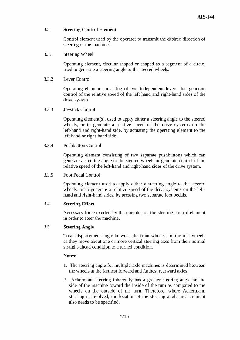
3.3 Steering Control Element
Control element used by the operator to transmit the desired direction of
steering of the machine.
3.3.1 Steering Wheel
Operating element, circular shaped or shaped as a segment of a circle,
used to generate a steering angle to the steered wheels.
3.3.2 Lever Control
Operating element consisting of two independent levers that generate
control of the relative speed of the left hand and right-hand sides of the
drive system.
3.3.3 Joystick Control
Operating element(s), used to apply either a steering angle to the steered
wheels, or to generate a relative speed of the drive systems on the
left-hand and right-hand side, by actuating the operating element to the
left hand or right-hand side.
3.3.4 Pushbutton Control
Operating element consisting of two separate pushbuttons which can
generate a steering angle to the steered wheels or generate control of the
relative speed of the left-hand and right-hand sides of the drive system.
3.3.5 Foot Pedal Control
Operating element used to apply either a steering angle to the steered
wheels, or to generate a relative speed of the drive systems on the left-
hand and right-hand sides, by pressing two separate foot pedals.
3.4 Steering Effort
Necessary force exerted by the operator on the steering control element
in order to steer the machine.
3.5 Steering Angle
Total displacement angle between the front wheels and the rear wheels
as they move about one or more vertical steering axes from their normal
straight-ahead condition to a turned condition.
Notes:
1. The steering angle for multiple-axle machines is determined between
the wheels at the farthest forward and farthest rearward axles.
2. Ackermann steering inherently has a greater steering angle on the
side of the machine toward the inside of the turn as compared to the
wheels on the outside of the turn. Therefore, where Ackermann
steering is involved, the location of the steering angle measurement
also needs to be specified.

AIS-144
4/19
A steering angle accomplished by a combination of geometries
incorporating Ackermann steering is included, and also requires the
location of the steering angle measurement to be specified.
3.6 Tyre Circle
Outer tyre clearance diameter determined in accordance with clause 9.
3.7 Working Circuit Pressure
That nominal pressure applied to the specific circuit by the pump(s).
3.8 Transfer Device
Parts of the steering system (3.1) being used to transfer forces (actuation
forces and steering forces) and/or steering commands between the
steering control element (3.3), and if applicable, the steering power
source (3.2).
Note:
The steering forces and/or steering commands can be transferred
- mechanically,
- hydraulically,
- electrically,
- electronically,
or as a combination of these.
3.9 Steered Wheels
Wheels whose direction of movement can be directly or indirectly
modified in order to determine the machine′s direction of travel.
3.10 Safe State
State applied automatically or manually, after a malfunction of the
steering-control system whereby the controlled equipment, process or
system is stopped or switched to a safe mode in order to prevent
unexpected movements or potentially hazardous release of stored
energy.
Note: Safe state is a function of many factors, including operating
conditions, the technologies involved, fault detection capabilities and the
safety concept. For electro-hydraulic steering control systems, disabling
the electronic portions during a fault and relying on the hydraulic
steering system is just one of several ways to reach a safe state.
4.0 GENERAL REQUIREMENTS
4.1 All Steering Systems
The following requirements apply to all steering systems within the
scope of this Indian Standard.
AIS-144
5/19
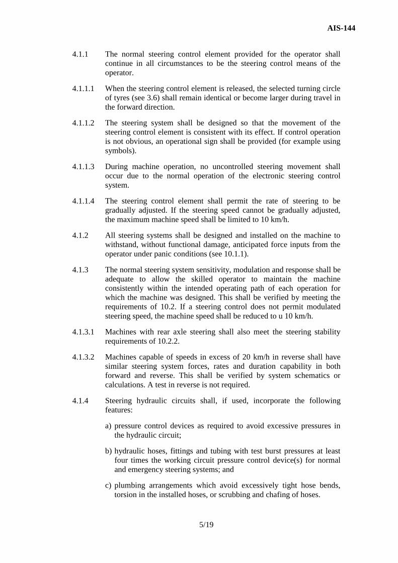
4.1.1 The normal steering control element provided for the operator shall
continue in all circumstances to be the steering control means of the
operator.
4.1.1.1 When the steering control element is released, the selected turning circle
of tyres (see 3.6) shall remain identical or become larger during travel in
the forward direction.
4.1.1.2 The steering system shall be designed so that the movement of the
steering control element is consistent with its effect. If control operation
is not obvious, an operational sign shall be provided (for example using
symbols).
4.1.1.3 During machine operation, no uncontrolled steering movement shall
occur due to the normal operation of the electronic steering control
system.
4.1.1.4 The steering control element shall permit the rate of steering to be
gradually adjusted. If the steering speed cannot be gradually adjusted,
the maximum machine speed shall be limited to 10 km/h.
4.1.2 All steering systems shall be designed and installed on the machine to
withstand, without functional damage, anticipated force inputs from the
operator under panic conditions (see 10.1.1).
4.1.3 The normal steering system sensitivity, modulation and response shall be
adequate to allow the skilled operator to maintain the machine
consistently within the intended operating path of each operation for
which the machine was designed. This shall be verified by meeting the
requirements of 10.2. If a steering control does not permit modulated
steering speed, the machine speed shall be reduced to u 10 km/h.
4.1.3.1 Machines with rear axle steering shall also meet the steering stability
requirements of 10.2.2.
4.1.3.2 Machines capable of speeds in excess of 20 km/h in reverse shall have
similar steering system forces, rates and duration capability in both
forward and reverse. This shall be verified by system schematics or
calculations. A test in reverse is not required.
4.1.4 Steering hydraulic circuits shall, if used, incorporate the following
features:
a) pressure control devices as required to avoid excessive pressures in
the hydraulic circuit;
b) hydraulic hoses, fittings and tubing with test burst pressures at least
four times the working circuit pressure control device(s) for normal
and emergency steering systems; and
c) plumbing arrangements which avoid excessively tight hose bends,
torsion in the installed hoses, or scrubbing and chafing of hoses.

AIS-144
6/19
4.1.5 Steering system reliability shall be enhanced by the selection and design
of components arranged so that inspection and maintenance can be
readily performed.
4.1.6 Steering system disturbances shall meet the conditions given in 4.1.6.1
and 4.1.6.2.
4.1.6.1 Steering system disturbances due to other machine functions shall be
minimized by appropriate arrangement and geometry. Flexure or travel
of suspension elements, machine side inclinations or axle oscillations
and steering variations due to driving and braking torques at the wheels
are among the influences which shall be minimized by suitable system
arrangement and geometry.
4.1.6.2 Steering system disturbances due to the influences of external forces on
the machine within the applications for which the machine is designed
shall not significantly affect steering control.
4.1.7 Power-assisted and fully powered steering systems shall meet the
conditions given in 4.1.7.1 and 4.1.7.3.
4.1.7.1 These systems should preferably be separate from other power systems
and circuits. Where this is not the case, the power-assisted and fully
powered steering systems shall have priority over other systems or
circuits except for an emergency steering system and emergency
stopping system which shall be maintained at the level of performance
specified in ISO 3450 (Doc No.1236) .
4.1.7.2 If other systems (consumers) are provided with power from the normal
steering power source, any failure in these systems (consumers) shall be
considered the same as a failure in the normal steering power source.
4.1.7.3 A change in ratio between the steering control element and steered
wheels is permissible after failure of the normal steering power source,
provided the requirements of 10.3 are met.
4.1.8 For machines equipped with an emergency steering system, the system
should preferably be separate from other power systems and circuits.
Where this is not the case, the emergency steering devices and circuits
shall have priority over all other systems or circuits except for the
emergency stopping system, which shall be maintained at the level of
performance specified in ISO 3450 (Doc No.1236).
4.1.9 The operator’s manual for machines equipped with an emergency
steering system shall include the following information:
a) an indication that the machine is equipped with an emergency steering
system;
b) the emergency steering capability limitations; and
c) the field test procedure for verifying that the emergency steering
system is functional.

AIS-144
7/19
4.1.10 Unintentional Operation
All steering control elements, except for the steering wheel, shall be
designed, arranged (i.e. operator station layout), taken out of service
(that is, interlocked) or secured such as to reduce the possibility of
unintentional activation when a person is entering or leaving the operator
area.
4.2 Steering Systems with Normal and Additional Steering Control
Elements
If more than one steering control element is to be used, in addition to the
requirements of 4.1, the following requirements shall also be fulfilled:
4.2.1 If a conventional steering wheel is one of the steering control elements,
it shall always be activated and have a higher priority than any other
steering control element and shall be considered as the normal steering
control element.
4.2.2 Steering control elements that can be activated/deactivated or which
have a restricted speed range shall have visible or audible indication to
the operator when activated.
4.2.3 If use of a steering control element is limited to a certain travel speed in
accordance with the steering test specified in 10.4, the travel speed of the
machine shall be restricted by design to that speed when the steering
control element is activated.
4.2.4 The function of the additional steering control element shall be capable
of being switched off or disabled, if it is required to be disabled for
travel on public roads.
4.3 Steering Systems with Electrical/Electronic Transfer Device
In addition to the requirements of 4.1, these steering systems shall also
meet the requirements of ISO 15998:2008, or ISO 13849:2012 or IEC
62061, as applicable, and the following.
4.3.1 In the case of a single failure of the electrical/electronic steering control
system that results in a hazardous condition and where the driving speed
of the machine is greater than 10 km/h, the steering system shall pass
into the safe state.
4.3.2 For machines having a speed greater than 20 km/h when operated with
electrical/electronic steering control system, the following performance
criteria shall be met:
a) the steering performance shall be maintained also in case of a single
failure 2);
b) the probability of unintended steering shall be minimized;
c) the operator shall be warned in case of a failure 2).

AIS-144
8/19
4.3.3 In the case of failure in the power source for the additional steering
control element and if the normal steering control element is not
affected, requirement a) and b) above do not apply.
4.3.4 The requirements specified in 4.3.2 shall be verified by relevant risk
analysis methods, such as FMEA, FTA, ETA or similar, as specified by
the manufacturer.
5.0 ERGONOMIC REQUIREMENTS
The following requirements apply to all steering systems within the
scope of this Standard.
5.1 The machine shall steer in the direction that corresponds to the direction
of movement of the steering control element: that is, steering-wheel
rotation shall be such that the clockwise rotation will turn the machine to
the right; counterclockwise rotation will turn the machine to the left.
Operation of the steering control element shall be in accordance with
IS/ISO 10968:2004 and, as applicable, with the normal functioning of
the machine.
5.2 The steering effort, as defined in 3.4, shall be as low as practical and
shall not exceed the values given in 5.2.1 and 5.2.2.
5.2.1 The steering effort for normal steering systems using a steering wheel
shall not exceed 115 N when specified for the steering tests according to
clause 10.0.
The steering actuation forces for operating elements - apart from the
steering wheel - shall be in accordance with Table 1.
5.2.2 The steering effort for emergency steering systems shall not exceed 350
N for the steering tests according to clause 10.
5.3 Steering control element movement to produce a given result shall not
vary by more than 25 percent between right and left turns up to a 30°
steering angle. This may be shown by calculations. For Ackermann
steering, this angle applies to the wheels toward the inside of the turn.
5.4 When continued moving of the steering control element is required to
continue changing the steering angle, it is desirable to make steering
control movement for a given steering angle change greater in the
vicinity of the straight-ahead position, such as is commonly achieved
with variable rate worm steering gears.

AIS-144
9/19
Table 1
Control actuating forces
(Clause 5.2.1)
S. No Control-actuating force, in
Newton
Max Normal
(frequent
operation)
Min a
1. Hand
lever, forward/backward
lever, sideways
brake lever, upwards
230
100
400
80
60
60
20
15
15
2. Foot
pedal
tread, centre-pivoted
450
230
120 b
50
30
30
3. Toe
pedal
90
50
12
4. Fingertip
lever or switch
25
10
2
a For information only. Since the actuating force can be variable along
the travel of the control lever, the indicated values are intended to be
achieved during the movement and, in particular, before any
engagement into a detent position.
b With back support: 150 N.
6.0 PERFORMANCE REQUIREMENTS
6.1 Normal Steering
Steering effort (see 3.4) for normally operating systems, whether
manual, power-assisted, or fully powered, shall not exceed 115 N when
negotiating the test course described in 10.2.3.
6.2 Emergency Steering with Power-Assisted Steering
6.2.1 Steering effort (see 3.4) shall not exceed 350 N during the emergency
steering tests according to 10.3.5 and 10.3.6. If this requirement is not
met, the steering system shall be classified and tested as a fully powered
steering system.
6.2.2 A warning device indicating a normal steering power source failure is
required. This warning device shall be audible or visual, and shall be
activated by failure of the normal steering power source. However, no
emergency steering power source or warning device is required,
provided that the emergency steering capability remains within the limits
specified in 6.2.1, regardless of time or number of steering applications,

AIS-144
10/19
and that either a significant increase in steering effort or a significant
increase in steering wheel movement for a given amount of steering
gives a definite indication to the operator of normal steering power
source failure.
6.2.3 This emergency steering system shall also function with reverse machine
movement if the maximum rated speed in reverse exceeds 20 km/h.
6.3 Emergency Steering with Fully Powered Steering
6.3.1 For machines equipped with an emergency steering system, the
emergency steering power source shall be as defined in 3.2.2.
6.3.2 Steering effort shall not exceed 350 N when tested in accordance with
10.3.5, 10.3.6 and 10.5.4.
6.3.3 A warning device indicating a normal steering power source failure is
required. This warning device shall be audible or visual, and shall be
activated by failure of the normal steering power source.
6.3.4 This emergency steering system shall also function with reverse machine
movement if the maximum rated speed in reverse exceeds 20 km/h.
6.4 All Steering Systems
All steering systems (normal and emergency) shall remain functionally
undamaged after testing in accordance with 10.1.1.
7.0 STEERING TEST COURSE
7.1 All steering tests shall be performed on courses made on a compacted
earth or paved surface which is flat and which has no more than 3
percent grade in any direction. (see clause 9, 10.2.1 and 10.3.3, and Fig.
1, 2 and 3.
7.2 The test course dimensions shown in Fig. 1 shall be determined
according to tyre circle, wheelbase, width over tyres and machine type.
7.3 The stated minimum values in Fig. 1 are set forth to maintain a
reasonable course for the smallest machines.
7.4 The wheelbase for a multiple-axle machine for establishing the Fig. 1
test course dimensions is the distance between the most forward axle and
the most rearward axle.
7.5 The mirror image of the test course shown in Fig. 1 may be used.
7.6 Machines with optional tyre sizes shall be tested with tyres approved by
the manufacturer having the narrowest tyre tread width.
Except for the alternative test course for Figure 3, machines with
optional tyre sizes shall be tested with the tyres approved by the
manufacturer that have the narrowest tyre tread width.
7.7 Additional steering tests shall be performed according to 10.4, with the
additional steering control elements lever control, joystick control and
pushbutton control.

AIS-144
11/19
8.0 MACHINE SPECIFICATIONS FOR TEST
8.1 Scrapers and dumpers shall be at the manufacturer’s rated maximum
gross mass and axle distribution, including the mass of the heaviest
combination of equipment and attachments approved by the
manufacturer, an operator of 75 kg and a full fuel tank.
8.2 Wheeled loaders, wheeled dozers, excavators and graders shall be at the
manufacturer’s empty machine mass, including the mass of the heaviest
combination of equipment and attachments approved by the
manufacturer which produce the greatest load on the steered axle(s), an
operator of 75 kg and a full fuel tank.
8.3 All component parameters related to steering capability shall be within
the manufacturer's specifications, that is, tyre size and pressure,
hydraulic fluid pressure and flow, warning device actuation point, etc.
9.0 TYRE CIRCLE TEST PROCEDURE
The tyre circle (used in calculating the test course dimensions for Fig. 1
and Fig. 2) is the outer tyre clearance diameter as determined in ISO
7457:1997 and the following.
9.1 Use only the normal steering control element (for example steering
wheel) and the normal steering system. Controls of other functions that
can affect the steering path obtained shall not be used (for example
steering brakes, grader wheel lean, grader rear bogie steer).
9.2 For machines with different right- and left-hand steering circles, use the
smaller tyre circle in calculating the test course dimensions.
9.3 Machines with three or more axles which include towed trailing units
shall have the tyre circle determined without any semi-trailed or trailing
units being towed in order to preclude steering stop interference between
the trailing portions and the leading unit.
10.0 STEERING TESTS
10.1 Tests with All Steering Systems
10.1.1 Steering systems with a steering wheel as the steering control element
shall resist a force of 900 N applied to the steering control element in the
direction of the control element movement (see 4.1.2) without any
restriction of their function.
Other steering control elements shall resist the double load of the
maximum operating force as defined in Table 1.
10.1.2 Machine tyres shall remain within the boundaries of the test courses as
shown in Fig. 1 and Fig. 2, excepting machines with three or more axles
which include a towed semi-trailed or trailing section or unit(s), where
the tyre path of those semi-trailed or trailing unit(s) is excluded.

AIS-144
12/19
10.2 Tests with Normal Steering System
10.2.1 The steering system performance shall be sufficient to maintain the
machine tyres within a straight course 100 m long and having a width of
1.25 times the maximum width over tyres while travelling at maximum
forward speed. Normal operator steering corrections are permissible.
10.2.2 Machines with rear axle steering shall be driven at 8 km/h ± 2 km/h in a
circular path with a diameter corresponding to approximately half of the
largest steering angle. When releasing the steering control element, the
steering angle shall not increase.
10.2.3 The steering system shall provide sufficient capability to maintain the
machine tyres (see 10.1.2) within the test course shown in Fig. 1,
constructed in accordance with 7, in forward travel at a sustained speed
of 16 km/h ± 2 km/h, from the time the axes of the front wheels enter the
course until the axes of the front wheels reach the end of the course. The
steering effort shall be recorded and shall not exceed 115 N. Several
practice runs are permitted to allow the operator to develop an even,
modulated application of muscular force on the steering control element.
10.3 Tests with Emergency Steering System
10.3.1 Check the emergency steering warning device system for proper
functioning in accordance with 6.2.2 and 6.3.3.
10.3.2 The power for the normal steering system shall be disconnected if
engine-driven because engine power is employed to drive the machine
through the test courses specified in 10.3.3, 10.3.5, 10.3.6 and 10.3.8.
10.3.3 The emergency steering system performance shall be sufficient to
maintain the machine tyres (see 10.1.2) within a straight course 100 m
long and having a width of 1.25 times the maximum width over tyres
while travelling at 16 km/h ± 2 km/h. Normal operator steering
corrections are permissible.
10.3.4 Emergency steering power available at the beginning of any emergency
steering test run shall be no more than is normally available at the instant
a normal steering power source failure is indicated.
10.3.5 Emergency steering shall provide an adequate steering force and steering
duration to maintain the machine tyres (see 10.1.2) within the test course
(as determined from Fig. 1) at 8 km/h ± 2 km/h, with the machine
moving continuously at that speed from the time the axes of the front
wheels enter the course.
10.3.6 Emergency steering shall provide an adequate steering force and steering
rate to maintain the machine tyres (see 10.1.2) within the test course
(as determined from Fig. 1) at 16 km/h ± 2 km/h, with the machine
moving continuously at that speed from the time the axes of the front
wheels enter the course until the axes of the front wheels reach the end
of the course.

AIS-144
13/19
10.3.7 During the tests according to 10.3.5 and 10.3.6, the steering effort shall
be recorded and shall not exceed 350 N. Several practice runs are
permitted to allow the operator to develop an even, modulated
application of the muscular force on the steering control element.
10.3.8 The emergency steering response test specified in this clause shall be
conducted by driving the machine through the test course as shown in
Fig. 2, at 16 km/h ± 2 km/h. This test shall be conducted with the
mirror image of the course shown in Fig. 2 if the Fig. 1 test course was
conducted with its own mirror image. Enter the test course with the
emergency steering system capability as normally available. Initiate a
turn at point A, as shown in Fig. 2. The start of steering control
actuation should trigger a ground marker located under the front axle,
and simultaneously simulate a failure of the normal steering power
source(s). The machine shall complete a 90° turn with the tyre track
paths remaining within the boundary specified.
10.4 Steering Test with Additional Steering Control Elements
Additional steering control element(s) shall be tested according to
Fig. 1. In the case of failure, the highest permitted speed shall be
defined according to Fig. 3.
Machine tyres shall remain within the boundaries of the test course as
shown in Fig. 3, excepting machines with three or more axles which
include a towed semi-trailed or trailing section or unit(s), where the tyre
path of those semi-trailed or trailing unit(s) is excluded (other than
avoiding the obstacle).
None of the cones shall be run over.
The machine shall be controllable as a comparable machine with a
steering-wheel as operating element and shall provide the same level of
safety and efficiency.
Zone 1: The maximum speed should be realized in zone 1. The
machine shall enter zone 2 centered between the cones and parallel to
the course. Speed may only be reduced after the front edge of the
machine has reached the first group of cones.
Zone 2: In this zone, the operator is permitted to do anything that is
required for keeping or reducing speed, except for using the brakes.
The machine shall swerve around the single cone; additional
manoeuvres are not permitted (for example a loop turn).
Zone 3: In this zone, the operator may use the brakes after the wheel
centre of the front tyre has passed the cones. The machine shall be able
to stay within the course until coming to a complete stop.
10.5 Alternative steering tests
For rubber-tyred earth-moving machines the steering tests in this clause
may be used as an alternative to those tests in clause 9, 10.2.3 and
10.3.5 to 10.3.8 of this Indian Standard.

AIS-144
14/19
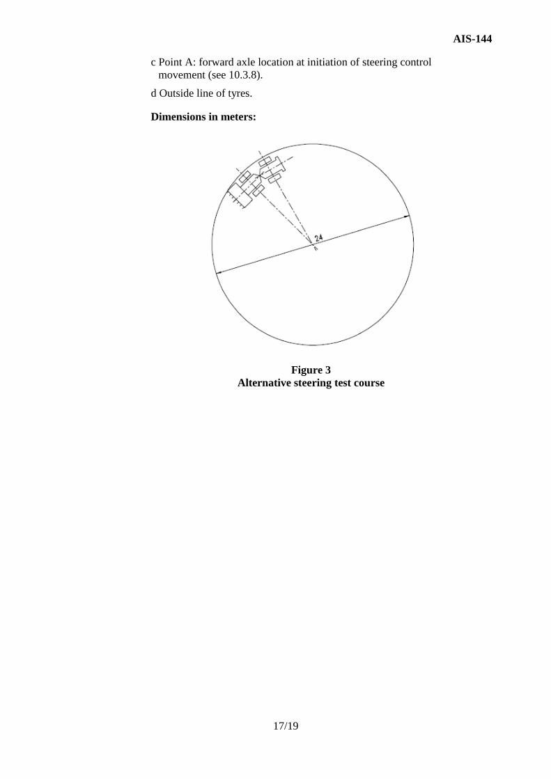
10.5.1 Alternative Test Course
The alternative test course is a test course having a machine clearance
diameter of 24 m on a surface as specified in 7.1 (see Fig. 3).
10.5.2 Test Steering Angle
The steering angle for subsequent use in this test shall be determined to
the left and right as follows.
10.5.2.1 Use only the normal steering control element (for example steering
wheel) and the normal steering system. Controls of other functions that
may affect the steering path obtained shall not be used (for example
steering brakes, grader wheel lean, grader rear bogie steer).
10.5.2.2 The machine shall be steered into the test course and driven in a
continuous circular path at 3 km/h ± 1 km/h. To determine the steering
angle corresponding to the test course according to 10.5.1, the
outermost part of the machine and its equipment shall follow the test
course (see Fig. 3).
10.5.3 Test with Normal Steering Systems
The steering system shall provide sufficient capability to steer the
machine from straight-ahead position to the steering angle as
determined from 10.5.2 within a time of 4 s. The forward travel speed
shall be 10 km/h ± 2 km/h and the steering effort shall not exceed
115 N. Tests shall be made turning to both the left hand and right-hand
side.
10.5.4 Tests with Emergency Steering Systems
10.5.4.1 Emergency steering shall provide adequate steering force and steering
duration to steer the machine continuously without interruption from
straight-ahead position to the left steering angle determined from
10.5.2, afterwards to the right steering angle and finish in the straight-
ahead position. The forward travel speed shall be 10 km/h ± 2 km/h and
the steering effort shall not exceed 350 N.
10.5.4.2 Emergency steering shall provide adequate steering force and steering
rate to steer the machine from straight-ahead position to the steering
angle determined from 10.5.2 within a time of 6 s. The forward travel
speed shall be 10 km/h ± 2 km/h and the steering effort shall not exceed
350 N. Tests shall be made turning to both the left-hand and right-hand
side.
10.5.4.3 An emergency steering response test shall be conducted by driving the
machine from straight-ahead position to the steering angle as
determined from 10.5.2. At the start of steering control actuation, a
failure of the normal steering power source(s) shall be simulated. The
time from the start of steering control actuation to the steering angle
specified in 10.5.2 shall not exceed 6 s. The forward travel speed shall
be 10 km/h ± 2 km/h and the steering effort shall not exceed 350 N.
The test shall be made turning to the side of the greatest time as
determined in 10.5.4.2.
AIS-144
15/19
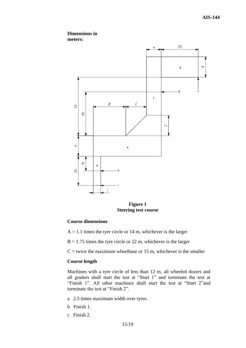
Dimensions in
meters:
Figure 1
Steering test course
Course dimensions
A = 1.1 times the tyre circle or 14 m, whichever is the larger
B = 1.75 times the tyre circle or 22 m, whichever is the larger
C = twice the maximum wheelbase or 15 m, whichever is the smaller
Course length
Machines with a tyre circle of less than 12 m, all wheeled dozers and
all graders shall start the test at “Start 1” and terminate the test at
“Finish 1”. All other machines shall start the test at “Start 2”and
terminate the test at “Finish 2”.
a 2.5 times maximum width over tyres.
b Finish 1.
c Finish 2.

AIS-144
16/19
d Corridor 3.
e Corridor 4.
f Corridor 2.
g Corridor 1.
h Start 1.
i Start 2.
j 1.25 times maximum width over tyres.
Dimensions in meters:
Figure 2
Emergency steering response
Key
A = 1,1 times the tyre circle or 14 m, whichever is the larger
a Perpendicular to original direction of travel.
b Original direction of travel.
AIS-144
17/19
c Point A: forward axle location at initiation of steering control
movement (see 10.3.8).
d Outside line of tyres.
Dimensions in meters:
Figure 3
Alternative steering test course

AIS-144
18/19
ANNEX- A
(See Introduction)
COMPOSITION OF AISC PANEL ON EARTH MOVING MACHINERY-
RUBBER TYRED MACHINES-STEERING REQUIREMENTS*
Convener
Mr. A. A. Badusha The Automotive Research Association of India (ARAI)
Members Representing
Mr. K. B. Patil The Automotive Research Association of India (ARAI)
Mr. Saurabh Dalela JCB India Ltd.,
Mr. Karthik Kaliappan John Deere India Pvt Ltd.
Mr. K.Vijay Ajax Fiori Engineering (I) Pvt. Ltd
Mr. K. Reji Jose Caterpillar India Ltd.
Mr. Bhaskaran Venkataramani Caterpillar India Ltd.
Mr. Vivek Rawat JCB India Ltd.,
Mr. Suresh Kumar M. Larsen & Toubro Limited
Mr. Rajeev Shalia Case Construction Equipment
Mr. G. Rajendra. Mahindra& Mahindra Construction Equipment Division
Mr. M. Rajendran Komatsu India Pvt. Ltd.
Mr. R. Ashok Volvo Construction Equipment Ltd.,
Mr. S. G. Roy Indian Earthmoving & Construction Industry Association Ltd.
* At the time of approval of this Automotive Industry Standard (AIS)

AIS-144
19/19
ANNEX- B
(See Introduction)
COMMITTEE COMPOSITION *
Automotive Industry Standards Committee
Chairperson
Mrs. Rashmi Urdhwareshe Director
The Automotive Research Association of India, Pune
Members Representing
Shri Priyank Bharti Ministry of Road Transport and Highways
(Dept. of Road Transport and Highways), New Delhi
Representative from Ministry of Heavy Industries and Public Enterprises
(Department of Heavy Industry), New Delhi
Shri S. M. Ahuja Office of the Development Commissioner, MSME, Ministry
of Micro, Small and Medium Enterprises, New Delhi
Shri Shrikant R. Marathe Former Chairman, AISC
Shri R.R. Singh Bureau of Indian Standards, New Delhi
Director Central Institute of Road Transport, Pune
Director Indian Institute of Petroleum, Dehra Dun
Director Vehicles Research and Development Establishment,
Ahmednagar
Director International Centre for Automotive Technology
Director Global Automotive Research Centre
Director Indian Rubber Manufacturers Research Association
Representatives from Society of Indian Automobile Manufacturers
Shri T. R. Kesavan Tractor Manufacturers Association, New Delhi
Shri Uday Harite Automotive Components Manufacturers Association of
India, New Delhi
Member Secretary
Shri Vikram Tandon
Dy. General Manager
The Automotive Research Association of India, Pune
* At the time of approval of this Automotive Industry Standard (AIS)