earthing • copper welding...earthing electrodes v1. 2013 7 1. earthing electrodes 1.1 earthing...
TRANSCRIPT

EARTHING • COPPER WELDING


TABLE OF CONTENTS
1. Earth electrode __________________________________________ 7
1.1 Earth rods _________________________________________ 7
1.2 Accessories for earth rods _________________________ 11
1.3 Rod connections _________________________________ 14
1.4 Grid, earthing plates and duckfoot ___________________ 15
2. Connections for round and fl at conductors ________________ 17
2.1 Connectors ______________________________________ 17
2.2 Crossed-shape, splice and earthing connectors _______ 22
3. Flat and round conductor fi xing accessories _______________ 26
3.1 Tightening clamps, collars and brackets ______________ 26
3.2 Terminals ________________________________________ 30
3.3 Vertical or horizontal mountings _____________________ 33
3.4 Mountings for roofs _______________________________ 37

4. Lightning protection _____________________________________ 38
4.1 Pda _____________________________________________ 38
4.2 Lightning rod _____________________________________ 39
4.3 Brackets _________________________________________ 40
4.4 Accessories for downpipes _________________________ 42
6. Conductors _____________________________________________ 52
6.1 Conductors ______________________________________ 52
6.2 Round conductors ________________________________ 53
6.3 Flat conductors ___________________________________ 54
6.4 Cu and Ag conductors _____________________________ 55
6.5 Round and fl at wire ropes __________________________ 56
5. Equipotential links _______________________________________ 45
5.1 Sinker bars and solid copper bars ___________________ 45
5.2 Equipotentiality bars _______________________________ 46
5.3 Clamps __________________________________________ 49
5.4 Clamping rings ___________________________________ 51

7. Copper alumino-thermic welding ________________________ 58 7.1 Cable / Cable _____________________________________ 66
7.2 Cable / Earth rod __________________________________ 77
7.3 Earth rod / Earth rod _______________________________ 82
7.4 Cable / Steel re-bar ________________________________ 83
7.5 Cable / Steel surface ______________________________ 89 7.6 Cable / Steel pipe _________________________________ 97
7.7 Cable / Bus bar ___________________________________ 98
7.8 Bus bar / Bus bar ________________________________ 108
7.9 LsVIP and ELPA TUBO __________________________ 117
- Lid that prevents spattering.
- Lid that reduces the smoke emission.
- Remote ignition device and versatil ignition system.
- Advantages of these NEW procedures.

EARTHING SYSTEMS
Although many elements as solid plates, radial strips, buried conductors, etc. are used as earthing electrodes, we refer here only to the deep driven rod electrodes because these are the most widely used due that this kind of electrodes are highly effi cient and comparatively low cost in installation.
The rod electrodes are driven into soil by hammering them so the contact resistance between the earth rod and the adjacent earth is negligible without needing of additional packing and the connection of the earth conductor is easily checkable at any time.
KLK’s earth rod electrodes consist of a high strength steel core with a copper coating, covered by a thick layer of pure electrolytic copper that is MOLECULARLY BONDED to the steel, combining a high mechanical strength and corrosion resistance.
Due to this molecular union, the steel and copper are physically inseparable and therefore:
• Against soil chemical agent attacks their performance is comparable to 99.9% pure copper.
• Their mechanical performance is like a solid steel rod, as both metals are present.
• As they are molecularly united there is no internal corrosion.
EARTH ELECTRODE RESISTANCE
In general, earthing resistance is:
• Directly proportional to the soil resistivity. • Inversely proportional to the length of the electrode.
Because of the high soil resistivity, earthing currents cause a great voltage drop and 90% of this voltage drop occurs around the electrode, practically in a radius of about 1.80 m from it.
Thus, to install a good earthing system the following factors must be taken into account:
• As the length of the rod is the most infl uential dimension, the best results will be obtained using the greater length possible.
• To reduce the resistance value several rods will be placed in parallel, yet separated by at least two meters.
• Soil resistivity decreases with moisture, which mainly depends on thedepth.

KLK Electro Materiales, s.l.uCamino de la Peñona 38B • 33211 GIJÓN • P.O. BOX 333-33206T. +34 985 321 850 F. +34 985 312 820 • e-mail: [email protected]
Dimensions indicated are nominal
EA
RT
HIN
G E
LEC
TR
OD
ES
V1.
201
3
7
1. EARTHING ELECTRODES1.1 EARTHING RODS
COPPERBONDED RODSDescription Manufactured from a high strength steel core
which is applied a copper plating molecularly bonded to the steel.
Material Core: Steel. Plating: Copper.
All our rod electrodes are marked on the surface with the “KLK” logo and the corresponding type.NOTE: Nominal and shank diameters do not correspond as they are threaded by rolling process.
TYPE UNE 202006 - 100 MICRONS
Cat Ref. Length (mm) x Ø Nominal Dia. (mm)
Ø Shank Dia. (mm) Kg/m
1,5 UNE 202006 142 1 1500 x 16 14.2 1.25
2 UNE 202006 142 1 2000 x 16 14.2 1.25
1,5 100M 180* 1500 x 20 18 1.25
2 100M 180* 2000 x 20 18 1.25Only supplied unthreaded.* Compliant with Standard copper thickness and length.
TYPE E - 350 MICRONS
Cat Ref. Cat. Ref. Threaded
Cat. Ref. Self-coupled
Length (mm) x Ø Nominal Dia. (“)
Ø Shank Dia.
(mm)Kg/m
E-10 34 E-10 34-RR E-10 34-AA 1000 x 3/4” 17.3 1.90
E-15 34 E-15 34-RR E-15 34-AA 1500 x 3/4” 17.3 1.90
E-20 34 E-20 34-RR E-20 34-AA 2000 x 5/8” 17.3 1.90
TYPE NU - 300 MICRONS
Cat Ref. Cat. Ref. Threaded
Length (mm) x Ø Nominal Dia. (mm)
Ø Shank Dia. (mm) Kg/ m
15 NU 146 2 15 NU 146 RR 1500 x 16 14.6 1.35
20 NU 146 2 20 NU 146 RR 2000 x 16 14.6 1.35
25 NU 146 25 NU 146 RR 2500 x 16 14.6 1.35
30 NU 146 30 NU 146 RR 3000 x 16 14.6 1.35
15 NU 183 2 15 NU 183 RR 1500 x 20 18.3 2.10
20 NU 183 2 20 NU 183 RR 2000 x 20 18.3 2.10
25 NU 183 25 NU 183 RR 2500 x 20 18.3 2.10
30 NU 183 30 NU 183 RR 3000 x 20 18.3 2.10
Add “R” if threaded on one end and “RR” if threaded on both ends.All rod electrodes are supplied in bundles of 5 units.
1 Rods certifi ed according to Standard UNE 202006:20102 Rods certifi ed according to UNE 21056:1981/UNE 21056:2000 ERRATUM

KLK Electro Materiales, s.l.uCamino de la Peñona 38B • 33211 GIJÓN • P.O. BOX 333-33206T. +34 985 321 850 F. +34 985 312 820 • e-mail: [email protected]
Dimensions indicated are nominal
1. EARTHING ELECTRODES1.1 EARTHING RODS
V1.
201
3E
AR
TH
ING
ELE
CT
RO
DE
S8
Self - Coupled
COPPERBOND RODSDescription Manufactured from a high strength steel core
which is applied a copper plating molecularly bonded to the steel .
Material Core: Steel. Plating: Copper
All our rods are marked on the surface with the “KLK” logo and the corresponding type. Other diameters and/or coatings upon request.
NOTE: Nominal and shank diameters do not correspond as they are threaded by rolling process.
TYPE J - 250 MICRONS
Cat. Ref. Cat. Ref.Threaded
Cat. Ref.Self-coupled
Length (mm) x Ø Nominal Dia.
(“)
Ø ShankDia.
(mm)Kg/m
J-10 58 J-10 58-RR J-10 58-AA 1000 x 5/8” 14.3 1.30
J-15 58 J-15 58-RR J-15 58-AA 1500 x 5/8” 14.3 1.30
J-20 58 J-20 58-RR J-20 58-AA 2000 x 5/8” 14.3 1.30
J-25 58 J-25 58-RR J-25 58-AA 2500 x 5/8” 14.3 1.30
J-30 58 J-30 58-RR J-30 58-AA 3000 x 5/8” 14.3 1.30
J-10 34 J-10 34-RR J-10 34-AA 1000 x 3/4” 17.3 1.90
J-15 34 J-15 34-RR J-15 34-AA 1500 x 3/4” 17.3 1.90
J-20 34 J-20 34-RR J-20 34-AA 2000 x 3/4” 17.3 1.90
J-25 34 J-25 34-RR J-25 34-AA 2500 x 3/4” 17.3 1.90
J-30 34 J-30 34-RR J-30 34-AA 3000 x 3/4” 17.3 1.90
TYPE ST - 150 MICRONS
Cat. Ref. Cat. Ref.Threaded
Length (mm) x Ø Nominal Dia. (mm)
Ø Shank Dia. (mm) Kg/m
10 ST 143 10 ST 143 - RR 1000 x 16 14.3 1.25
15 ST 143 15 ST 143 - RR 1500 x 16 14.3 1.25
20 ST 143 20 ST 143 - RR 2000 x 16 14.3 1.25
25 ST 143 25 ST 143 - RR 2500 x 16 14.3 1.25
30 ST 143 30 ST 143 - RR 3000 x 16 14.3 1.25
10 ST 180 10 ST 180 - RR 1000 x 18 18 1.98
15 ST 180 15 ST 180 - RR 1500 x 18 18 1.98
20 ST 180 20 ST 180 - RR 2000 x 18 18 1.98
25 ST 180 25 ST 180 - RR 2500 x 18 18 1.98
30 ST 180 30 ST 180 - RR 3000 x 18 18 1.98
Add “R” if threaded on one end and “RR” if threaded on both ends.
All the rod electrodes are supplied in bundles of 5 units.

KLK Electro Materiales, s.l.uCamino de la Peñona 38B • 33211 GIJÓN • P.O. BOX 333-33206T. +34 985 321 850 F. +34 985 312 820 • e-mail: [email protected]
Dimensions indicated are nominal
EA
RT
HIN
G E
LEC
TR
OD
ES
1. EARTHING ELECTRODES1.1 EARTHING RODS
V1.
201
3
9
All our rods are marked on the surface with the “KLK” logo and the corresponding type. Other diameters and/or coating upon request.
NOTE: Nominal and shank diameters do not correspond as they are threaded by rolling process.
COPPERBOND RODSDescription Manufactured from a high strength steel core
which is applied a copper plating molecularly bonded to the steel.
Material Core: Steel. Plating: Copper.
TYPE CG - 15 MICRONS
REF. Length x Ø Nominal Dia. (mm) Ø Shank Dia.(mm) Kg/U
10 CG 138 1000 x 13.8 13.8 1.20
15 CG 138 1500 x 13.8 13.8 1.80
20 CG 138 2000 x 13.8 13.8 2.40
GALVANISED STEEL RODSDescription Manufactured from a high strength steel core which is
applied a hot-dip galvanised coating.
Material Core: Steel. Plating: Hot-dip galvanised steel.
TYPE AG - 80 MICRONS
REF. Length x Ø Nominal Dia. (mm) Ø Shank Dia. (mm) Kg/U
10 AG 160 1000 x 16 16 2.89
15 AG 160 1500 x 16 16 4.04
20 AG 160 2000 x 16 16 5.19
STAINLESS STEEL RODSDescription Stainless steel rods. The Self-coupling rods have a
cone point and perforated head for its self-coupling.
Material Stainless Steel AISI 420-X30Cr13/16 mm.
TYPE I
Types Self- extensible Length x Ø Nominal Dia. (mm) Ø Shank Dia. (mm) Kg/m
I-1016 I-1016-AA 1000 x 16 16 1.5
I-1516 I-1516-AA 1500 x 16 16 2.25
I-2016 I-2016-AA 2000 x 16 16 3
All the rod electrodes are supplied in bundles of 5 units.

KLK Electro Materiales, s.l.uCamino de la Peñona 38B • 33211 GIJÓN • P.O. BOX 333-33206T. +34 985 321 850 F. +34 985 312 820 • e-mail: [email protected]
Dimensions indicated are nominal
1. EARTHING ELECTRODES1.1 EARTHING RODS
V1.
201
3E
AR
TH
NI G
ELE
CT
RO
DE
S10
All our rods are marked on the surface with the “KLK” logo and the corresponding type. Other diameters and/or coating upon request.
NOTE: Nominal and shank diameters do not correspond as they are threaded by rolling process.
ZINC RODS (CATHODIC PROTECTION )Description These electrodes have a steel core covered by a thick layer
of metallic Zinc and are suitable to be used as sacrifi cial anodes in cathodic protection systems to reduce the corrosion of structures or buried steel deposits.
Material Core: Electrogalvanised steel or hot-dip galvanised steel. Covering: Zinc bath in casting.
ZN RODSREF. Length x Ø Nominal Dia. (mm) Kg/U
10Zn30 1036 x 30 5.05
12Zn30 1200 x 30 6.10
15Zn35 1500 x 35 10.17
The lengths and diameters of the steel-zinc rods refer to the zinc coating.
TRACTOR RODDescription With this technique the earthing is performed directly
through the cable thereby avoiding corrosion. The admissible copper cable section shall be 25-29 mm2.
Material Core: Steel S235 J. Coating: Hot-dip galvanised a/Standard UNE-EN ISO 1461. Thickness ≥ 65 µm.
TRACTOR RODREF. Length x Ø Nominal Dia. (mm) Kg/U
PT-10166 1010 x 16.6 5.05
EPT-10166 1160 x 16.6 6.10
All rod electrodes are supplied in bundles of 5 units.

KLK Electro Materiales, s.l.uCamino de la Peñona 38B • 33211 GIJÓN • P.O. BOX 333-33206T. +34 985 321 850 F. +34 985 312 820 • e-mail: [email protected]
Dimensions indicated are nominal
EA
RT
HIN
G E
LEC
TR
OD
ES
V1.
201
3
11
1. EARTHING ELECTRODE1.2 EARTHING ROD ACCESSORIES
DRIVING HAMMERDescription Laminated steel hammer to drive rods of 20mm maximum
diameter.
Material Head: round laminated ST-52. Body: laminated steel pipe of 40x2 mm. Finish: Heat resistant aluminium paint.
MD-10
REF. Ø Nominal Dia. Rod size (mm)
DIMENSIONSKg/ U
L (mm) A(mm) D (mm) d (mm)
MD-10 20 1150 150 100 40 10
COUPLINGDescription Auxiliary part which ensures the coupling of the rod section
with another to drive the rod deeper.
Material Brass.
COUPLING M FOR THREADED AND UNTHREADED RODS
REF.DIMENSIONS
Kg/ UL (mm) D (mm) d (mm)
M-16 80 23 20.5 0,115
M-58 75 21 18.5 0,115
M-20 70 27 20 0,17
M-34 80 24 21.5 0,17
MC-58C 75 21 18,5 0,17
MC-54C 80 24 21,5 0,17
STUDDescription Hexagonal head stud designed to drive threaded rods.
Material Carbon steel.
TREF. T - 16 T - 58 T - 20 T - 34
Kg/u 0,09 0,09 0,16 0,16

KLK Electro Materiales, s.l.uCamino de la Peñona 38B • 33211 GIJÓN • P.O. BOX 333-33206T. +34 985 321 850 F. +34 985 312 820 • e-mail: [email protected]
Dimensions indicated are nominal
1. EARTHING ELECTRODES1.2 EARTHING ROD ACCESSORIES
V1.
201
3E
AR
TH
ING
ELE
CT
RO
DE
S12
DRIVING HEADDescription Auxiliary part to drive rods of 20mm maximum diameter.
It ensures the mechanical driving forces are directly transferred without damaging the rod or the coupling.
Material Body: Round calibrated steel S235 JR.Finish: Bi-chromated.
SN
REF. Ø Nominal Dia. rod size (mm)
DIMENSIONSKg/ U
L (mm) D (mm) d (mm)
SN 20 110 30 40 0.41
S-AA 3/4” 0.46
ELECTROLYTE SALTSDescription Electrolyte and hygroscopic salts which enable improving
the soil resistivity.This preparation achieves a notable reduction of the soil resistivity in high resistivity soils. Insoluble in water, non-corrosive, it is not affected by the soil’s chemical components.
Performance One dose of Protegel is recommended per cubic meter of earth, for the installation of an electrode at 2 to 3 meters length (one tub per rod).
PROTEGELREF. Kg/U U
PROTEGEL 6 1
METAL EARTH INSPECTION PITSDescription Metal cover to close inspection pits, installed on site, with
the earth sign stamped.
Material AC-M 150 Aluminium foundry.AC-M 200 Aluminium foundry.
AC-MCat. Ref. A D H Kg/ U
AC-M 150 AL 210 170 50 1,11
AC-M 200 FE 250 200 120 8

KLK Electro Materiales, s.l.uCamino de la Peñona 38B • 33211 GIJÓN • P.O. BOX 333-33206T. +34 985 321 850 F. +34 985 312 820 • e-mail: [email protected]
Dimensions indicated are nominal
EA
RT
HIN
G E
LEC
TR
OD
ES
1. EARTHING ELECTRODES1.2 EARTHING ROD ACCESSORIES
V1.
201
3
13
POLYESTER EARTH INSPECTION PITSDescription Bottomless earth inspection pits. Made in polyester, with
earthing sign stamped.
Material Polyester resin reinforced with fi breglass.
AC-CP (ROUND), AC-RP (SQUARE)
Cat.Ref. D (mm) A (mm) H (mm) Thickness (mm) Kg/U
AC - CP 20 200 285 500 2-3 1.40
AC - CP 30 300 400 520 2-3 2.40
AC - RP 40 450 450 490 >2.5 2.90
POLYESTER RECTANGULAR PITDescription Polyester rectangular pit. This pit is closed with bottom and
with punched holes. Cover with earthing sign stamped .
Material Polyester resin reinforced with fi breglass.
AC - RP 60Cat.Ref. A (mm) D (mm) H (mm) Thickness (mm) Kg/U
AC - RP 60 460 685 280 3 6
PVC RECTANGULAR PITDescription Siphon pit, accessible with cover and passable.
Material PVC.
AC - RPCat.Ref. A (mm) D (mm) H (mm) Kg/U
AC - RP 200 200 200 200 1.2
AC - RP 300 300 300 300 1.5
AC - RP 400 400 400 400 1.7
KLK Electro Materiales, s.l.uCamino de la Peñona 38B • 33211 GIJÓN • P.O. BOX 333-33206T. +34 985 321 850 F. +34 985 312 820 • e-mail: [email protected]
Las dimensiones indicadas son nominales
V1.
201
3E
AR
TH
ING
ELE
CT
RO
DE
S14
1. EARTHING ELECTRODES1.3 ROD CONNECTION
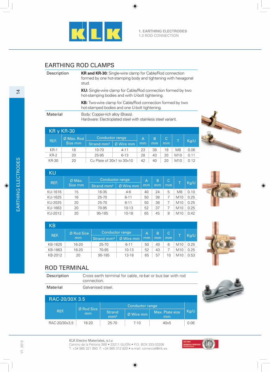
EARTHING ROD CLAMPSDescription KR and KR-30: Single-wire clamp for Cable/Rod connection
formed by one hot-stamping body and tightening with hexagonal stud.
KU: Single-wire clamp for Cable/Rod connection formed by two hot-stamping bodies and with U-bolt tightening.
KB: Two-wire clamp for Cable/Rod connection formed by two hot-stamped bodies and one U-bolt tightening.
Material Body: Copper-rich alloy (Brass).Hardware: Electroplated steel with stainless steel variant.
KR y KR-30
REF. Ø Máx. RodSize mm
Conductor range Amm
Bmm
Cmm T Kg/U
Strand mm² Ø Wire mm
KR-1 16 10-70 4-11 23 38 18 M8 0.06
KR-2 20 25-95 6-13 28 43 20 M10 0.11
KR-30 20 Cu Plate of 30x1 to 30x10 42 40 20 M10 0.12
KU
REF. Ø Máx. Size mm
Conductor range Amm
Bmm
Cmm T Kg/U
Strand mm² Ø Wire mm
KU-1616 15 16-35 4-6 40 24 5 M8 0.10
KU-1625 16 25-70 6-11 50 38 7 M10 0.25
KU-2025 20 25-70 6-11 50 38 7 M10 0.25
KU-1663 20 70-95 10-13 52 37 7 M10 0.25
KU-2012 20 95-185 10-18 65 45 9 M10 0.42
KB
REF. Ø Rod Size mm
Conductor range Amm
Bmm
Cmm T Kg/U
Strand mm² Ø Wire mm
KB-1625 16-20 25-70 6-11 50 40 6 M10 0.25
KB-1663 16-20 70-95 10-13 52 43 7 M10 0.25
KB-2012 20 95-185 13-18 65 57 10 M10 0.53
ROD TERMINALDescription Cross earth terminal for cable, re-bar or bus bar with rod
connection.
Material Galvanised steel.
RAC-20/30X 3.5
REF. Ø Rod Size mm
Conductor rangeKg/UStrand
mm² Ø Wire mm Max. Plate size mm
RAC-20/30x3,5 16-20 25-70 7-10 40x5 0.06

KLK Electro Materiales, s.l.uCamino de la Peñona 38B • 33211 GIJÓN • P.O. BOX 333-33206T. +34 985 321 850 F. +34 985 312 820 • e-mail: [email protected]
Dimensions indicated are nominal
EA
RT
HIN
G E
LEC
TR
OD
ES
V1.
201
3
15
1. EARTHING ELECTRODES1.4 EARTHING GRID, PLATE AND DUCKFOOT
EARTHING GRIDSDescription Copper earthing grids with or without solid band.
Material Body: copper.
GTC. GTC-SB. GRID WITH SOLID BAND
REF.Dimensions
Section Mesh (mm) Kg/U UA B
GTC-10/10/2 1000 1000 2x2 115 x 55 2 1
GTC-10/10/3 1000 1000 3x3 115 x 55 4 1
GTC-20/10/2 2000 1000 2x2 115 x 55 4 1
GTC-20/10/3 2000 1000 3x3 115 x 55 8 1
GTC-10/10/2SB 1000 1000 2x2 115 x 55 1.15 1
GTC-10/10/3SB 1000 1000 3x3 115 x 55 3.20 1
GTC-20/10/2SB 2000 1000 2x2 115 x 55 2.3 1
GTC-20/10/3SB 2000 1000 3x3 115 x 55 6.50 1
GTC-25/4/3SB 2500 400 3x3 115 x 55 2.6 1
OTHER DIMENSIONS UPON REQUEST
EARTH MESHDescription Copper grid with or without solid band. Welded by alumino-
thermal welding.
Material Body: copper.
GTC
REF.Dimensions
Section Mesh (mm) Kg/U UA B
GTC-20/10/2ALU*X 2000 1000 2x2 115 x 55 - 1
GTC-20/10/3ALU*X 2000 1000 3x3 115 x 55 - 1
GTC-25/4/3SB-2x25 mm 2400 400 3x3 115 x 55 2,83 1
OTHER DIMENSIONS UPON REQUEST

KLK Electro Materiales, s.l.uCamino de la Peñona 38B • 33211 GIJÓN • P.O. BOX 333-33206T. +34 985 321 850 F. +34 985 312 820 • e-mail: [email protected]
Dimensions indicated are nominal
1. EARTHING ELECTRODE1.4 EARTHING GRID, PLATE AND DUCKFOOT
V1.
201
3E
AR
TH
ING
ELE
CT
RO
DE
S16
EARTH CONDUCTORSDescription Earth plates.
Material Copper.
PTC
REF.Dimensions Thickness
(mm)Length of arms
(mm) Kg/U UA B
PTC-20/10/2 2000 1000 2 - 35 1
PTC-20/10/3 2000 1000 3 - 53 1
PTC-20/10/4 2000 1000 4 - 71 1
POSSIBILITY OF WELDING BY ALUMINO-THERMAL CONDUCTORS TO THE PLATE
PTC-20/10/X ALUX Y 2000 1000 X Y 50 1
EARTH PLATEDescription Copper plate of 2 mm thickness.
Material Plate: Electrolytic copper.Clamp TK 50T: Copper-rich alloy (Brass). Hardware: Stainless steel.
PTC
REF.Dimensions
Thickness (mm) Kg/U UA B
PLACA PAT 500x500 500 500 2 4,5 1
PLACA PAT 500x1000 500 1000 2 9 1
PLACA PAT 1000x1000 1000 1000 2 18 1
PO- 3XX/1XYDescription Duckfoot recommended to achieve a low inductance on the
earthing.
Material Tinned copper.
X : Length of the branched conductorsY : Length of the main conductor

KLK Electro Materiales, s.l.uCamino de la Peñona 38B • 33211 GIJÓN • P.O. BOX 333-33206T. +34 985 321 850 F. +34 985 312 820 • e-mail: [email protected]
Dimensions indicated are nominal
CO
NN
EC
TIO
N O
F R
OU
ND
AN
D F
LAT
CO
ND
UC
TO
RS
V1.
201
3
17
2. CONNECTION FOR ROUND AND FLAT CONDUCTORS 2.1 CONNECTORS
MISCELLANEAOUS CLAMPSDescription KBL: Two-wire clamp formed by two hot-stamping bodies
and tightening with one hexagonal stud.
KBH: Two-wire clamp formed by two hot-stamping bodies and tightening with two hexagonal studs.
KDP: Two-wire clamp formed by two hot-stamping bodies and tightening with one hexagonal stud.
Material Body: Copper-rich alloy (Brass).Hardware: Electro-galvanised steel with stainless steel variant.
KBL
REF.Conductor range A
mmB
mmC
mm T Kg/UStrand mm² Ø Wire mm
KBL-25 25-70 6-11 50 40 7 M 8x35 0.20
KBL-63 70-95 11-13 56 45 7 M 10x45 0.22
KBL-125 95-185 12-18 65 57 12.5 M 10x55 0.51
KBH
REF.Conductor range A
mmB
mmC
mm T Kg/UStrand mm² Ø Wire mm
KBH-25 25-70 6-11 50 40 7 M 8x35 0.22
KBH-63 70-95 11-13 54 45 7 M 10x45 0.26
KBH-125 95-185 13-18 65 57 12.5 M 10x55 0.54
KDP
REF.Conductor range A
mmB
mmC
mm T Kg/UStrand mm² Ø Wire mm
KDP-10/35/2 4-30 2-6 20 25 M6 0.027
KDP-10/50 10-50 4-9 23 30 M6 0.04
KDP-10/50/2 10-50 4-9 30 30 2xM6 0.07
KDP-16/95/2 16-95 4-13 30 37 2xM6 0.095
KDP-25/150 25-150 6-16 42 48 2xM8 0.198
KDP-50 16-50 4-9 25 33 5.5 M 8x30 0.07
KDP-95 25-95 6-13 30 47 6.5 M 8x35 0.118
KDP-150 35-150 7-16 35 52 7 M 10x40 0.175
KDP-240 95-240 12-20 40 63 12 2- M 8x60 0.35
KDP-16/150 16-150 4-16 50 53 11 2- M 8x45 0.25

KLK Electro Materiales, s.l.uCamino de la Peñona 38B • 33211 GIJÓN • P.O. BOX 333-33206T. +34 985 321 850 F. +34 985 312 820 • e-mail: [email protected]
Dimensions indicated are nominal
2. CONNECTION FOR ROUND AND FLAT CONDUCTORS 2.1 CONNECTORS
V1.
201
3C
ON
NE
CT
ION
OF
RO
UN
D A
ND
FLA
T C
ON
DU
CT
OR
S
18
MISCELLANEOUS CLAMPSDescription KZ: Two-cable cross clamp branch formed by three hot-stamped
bodies and with hardware tightening.
KM: Single-wire clamp for cable fi xing to metal structure formed by one hot-stamped body. The tightening of the cable and the fi xing to the structure is with hexagonal stud. It can not be mounted on concrete as the bolt head is recessed in the clamp and it can not be turned to crew it into the plug inserted in the concrete.
KML: Two-wire clamp to fi x two cables to a metal or concrete structure formed by one hot-stamped body. The tightening is with one hexagonal screw.
Material Body: Copper-rich alloy (Brass).Hardware: Electrogalvanised steel with stainless steel variant.
KZ
REF.Conductor range A
mmB
mmC
mm T Kg/UStrand mm² Ø Wire mm
KZ-25 25-70 6-11 44 44 7 M 8 0.24
KZ-63 70-95 10-13 62 62 12 M 10 0.835
KZ-100 95-185 12-18 62 62 12 M 10 0.835
KM
REF.Conductor range A
mmB
mmC
mm T Kg/UStrand mm² Ø Wire mm
KM-25 25-70 6-11 25 40 7.5 M 8x30 0.05
KM-63 70-95 10-13 35 45 11 M 10x35 0.11
KM-100 95-185 12-18 40 55 15 M 10x50 0.16
KML
REF.Conductor range A
mmB
mmC
mm T Kg/UStrand mm² Ø Wire mm
KML-25 25-70 6-11 50 40 7 M 8x35 0.14
KML-63 70-95 10-13 56 45 8.5 M 10x45 0.14
KML-125 95-185 12-18 65 57 12.5 M 10x55 0.29

KLK Electro Materiales, s.l.uCamino de la Peñona 38B • 33211 GIJÓN • P.O. BOX 333-33206T. +34 985 321 850 F. +34 985 312 820 • e-mail: [email protected]
Dimensions indicated are nominal
2. CONNECTION FOR ROUND AND FLAT CONDUCTORS 2.1 CONNECTORS
CO
NN
EC
TIO
N O
F R
OU
ND
AN
D F
LAT
CO
ND
UC
TO
RS
V1.
201
3
19
TERMINALS AND CONNECTORSDescription TK.P: Terminal for cable, formed by a round body and one
fl at blade. The tightening of the cable is with screw.
TK.T: Terminal for cable, formed by one round body and one fl at blade. The tightening of the cable is with hexagonal bolt.
Material Body and screw: Copper-rich alloy (Brass).Hardware: Electro-galvanised steel with stainless steel variant.
TK.P and TK.T
REF.Section Conductor
Strand mm² Ø Screw Hole Dia.Ø mm
Amm
Bmm
Cmm
Emm Kg/U
Mín. Máx.
TK 25 P 10 25 6.5 14 28 18 3 0.025
TK 50 P 25 50 8.5 19 38 24 4 0.06
TK 150 P 50 150 10.5 24 50 32 5 0.125
TK 300 P 95 300 12.5 35 76 44 7 0.34
TK 25 T 10 25 6.5 14 28 18 3 0.025
TK 50 T 25 50 8.5 19 38 24 4 0.06
TK 150 T 50 150 10.5 24 50 32 5 0.125
TK 300 T 95 300 12.5 35 76 44 7 0.34
TIGHTENING CONNECTORDescription CD: Copper alloy body with high mechanical resistance,
manufactured by hot-stamping and corrosion resistant.
CT: Copper alloy body with high mechanical resistance, manufactured by hot-stamping and corrosion resistant.
Material Body: Copper-rich alloy (Brass). Hardware: Electrogalvanised steel with stainless steel variant.
CD and CT
REF.Conductor range A
mm T Ømm Kg/100 U
Strand mm² Ø Wire mm
CD-10/70-8 10-70 3-11 24 M5 8 7.20 10-25
CD-10/70-10 10-70 3-11 24 M5 10 7.20 10-25
CD-10/70-12 10-70 3-11 24 M5 12 7.20 10-25
CD-25/120-12 25-120 6-15 30 M8 12 13.20 10-25
CT-10/70-8 10-70 3-11 24 M 5 8 8 10-25
CT-10/70-10 10-70 3-11 24 M 8 10 8 10-25
CT-25/120-12 25-120 6-15 30 M 8 12 18 10-25

KLK Electro Materiales, s.l.uCamino de la Peñona 38B • 33211 GIJÓN • P.O. BOX 333-33206T. +34 985 321 850 F. +34 985 312 820 • e-mail: [email protected]
Dimensions indicated are nominal
2. CONNECTION FOR ROUND AND FLAT CONDUCTORS 2.1 CONNECTORS
V1.
201
3C
ON
NE
CT
ION
OF
RO
UN
D A
ND
FLA
T C
ON
DU
CT
OR
S20
TIGHTENING CONNECTORDescription CE: Copper alloy body with high mechanical resistance,
manufactured by hot-stamping and corrosion resistant.
RD: Copper alloy body with high mechanical resistance, manufactured by hot-stamping and corrosion resistant.
RT: Copper alloy body with high mechanical resistance, manufactured by hot-stamping and corrosion resistant.
Material Body: Copper-rich alloy (Brass) .Hardware: Electrogalvanised steel with stainless steel variant .
CE
REF.Conductor range
Amm T Ø
mm Kg/100 UStrand mm² Ø Wire
(mm)
CE-10/70-8 10-70 4-11 24 M 5 8 7.60 10-25
CE-25/120/12 25-120 6-15 30 M 8 12 16.20 10-25
RD
REF.Conductor range
T Kg/100 UStrand mm² Ø Wire mm
RD-10/70 10-70 3-11 M6 10 10-25
RD-25/120 25-120 6-15 M8 13 10-25
RT
REF.Conductor range
T Kg/100 UStrand mm² Ø Wire mm
RT-10/70 10-70 4-11 M6 10.5 10-25
RT-25/120 25-120 6-15 M8 20 10-25

KLK Electro Materiales, s.l.uCamino de la Peñona 38B • 33211 GIJÓN • P.O. BOX 333-33206T. +34 985 321 850 F. +34 985 312 820 • e-mail: [email protected]
Dimensions indicated are nominal
2. CONNECTION FOR ROUND AND FLAT CONDUCTORS 2.1 CONNECTORS
CO
NN
EC
TIO
N O
F R
OU
ND
AN
D F
LAT
CO
ND
UC
TO
RS
V1.
201
3
21
CONNECTOR IN CDescription Clamp for branching by compression.
Material Tinned copper.
REF. A B C
Kg/100 UMin (mm²)
Max(mm²)
Min (mm²)
Max(mm²)
C1(mm)
C2(mm)
C6E 1.5 6 1.5 6 10 9 0.3 100
C10E 10 6 2x1.5 10 12.5 12 0.46 100
C16E1016
169
2x1.516 19 17 2 50
C25E252730
293550
106
2x1.5
291616
24.3 20 2.20 50
C35E3050
3550
25 2x1.5
3516
26.5 20 3.70 25
C50E5063
507075
162x1.5
503025
26.5 20 3.60 25
C70E 70 70 25 70 34 28 9.20 25
C75E757090
9595
303516
7570
41 30 8.70 25
C95E 75 95 75 95 41 30 14 25
C120E120150
120 150
356
120 50
45 30 16 25
C150E 150 150 75 150 45 30 12 10
C185E115150
185185
9560
185150
54 35 25 10
C240E 240 240 150 240 54 35 22 10
KLK Electro Materiales, s.l.uCamino de la Peñona 38B • 33211 GIJÓN • P.O. BOX 333-33206T. +34 985 321 850 F. +34 985 312 820 • e-mail: [email protected]
Dimensions indicated are nominal
V1.
201
3C
ON
NE
CT
ION
OF
RO
UN
D A
ND
FLA
T C
ON
DU
CT
OR
S
22
2. CONNECTION FOR ROUND AND FLAT CONDUCTORS 2.2 CROSS, SPLICE AND EARHTING CONNECTORS
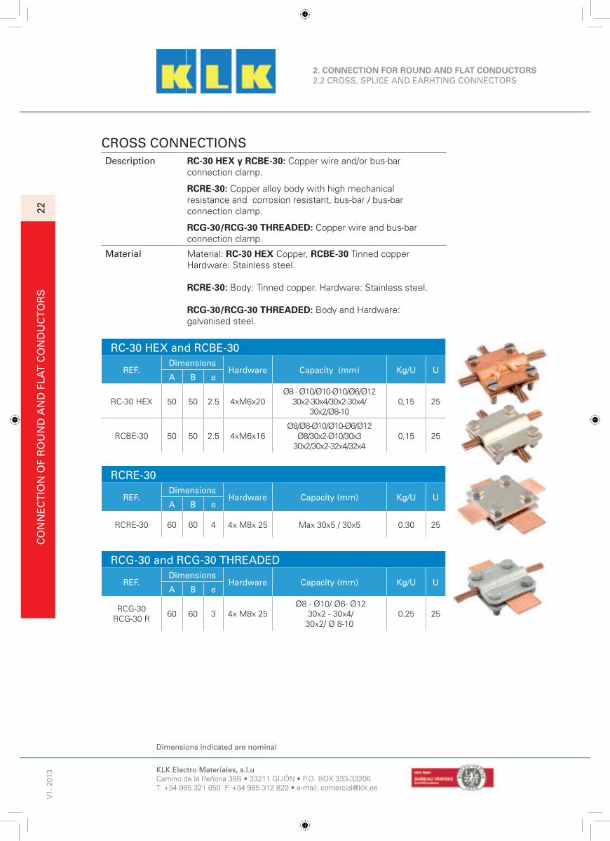
CROSS CONNECTIONSDescription RC-30 HEX y RCBE-30: Copper wire and/or bus-bar
connection clamp.
RCRE-30: Copper alloy body with high mechanical resistance and corrosion resistant, bus-bar / bus-bar connection clamp.
RCG-30/RCG-30 THREADED: Copper wire and bus-bar connection clamp.
Material Material: RC-30 HEX Copper, RCBE-30 Tinned copper Hardware: Stainless steel.
RCRE-30: Body: Tinned copper. Hardware: Stainless steel.
RCG-30/RCG-30 THREADED: Body and Hardware: galvanised steel.
RC-30 HEX and RCBE-30
REF.Dimensions
Hardware Capacity (mm) Kg/U UA B e
RC-30 HEX 50 50 2.5 4xM6x20Ø8 - Ø10/Ø10-Ø10/Ø6/Ø12
30x2-30x4/30x2-30x4/30x2/Ø8-10
0,15 25
RCBE-30 50 50 2.5 4xM6x16Ø8/Ø8-Ø10/Ø10-Ø6/Ø12
Ø8/30x2-Ø10/30x330x2/30x2-32x4/32x4
0,15 25
RCRE-30
REF.Dimensions
Hardware Capacity (mm) Kg/U UA B e
RCRE-30 60 60 4 4x M8x 25 Max 30x5 / 30x5 0.30 25
RCG-30 and RCG-30 THREADED
REF.Dimensions
Hardware Capacity (mm) Kg/U UA B e
RCG-30RCG-30 R
60 60 3 4x M8x 25 Ø8 - Ø10/ Ø6- Ø12
30x2 - 30x4/ 30x2/ Ø 8-10
0.25 25

KLK Electro Materiales, s.l.uCamino de la Peñona 38B • 33211 GIJÓN • P.O. BOX 333-33206T. +34 985 321 850 F. +34 985 312 820 • e-mail: [email protected]
Dimensions indicated are nominal
CO
NN
EC
TIO
N O
F R
OU
ND
AN
D F
LAT
CO
ND
UC
TO
RS
2. CONNECTION OF ROUND AND FLAT CONDUCTORS 2.2 CROSS, SPLICE AND EARHTING CONNECTORS
V1.
201
3
23
CROSS CONNECTIONS
Description RC-Ix: Connection clamp for cross conductors.RCR-30Ix: Bus-bar / Bus-bar connection clamp.RCR-30Ix/S: Copper wire and bus-bar connection clamp.
Material RC-IX y RCR-30Ix: Stainless steel.RCR-30Ix/S: Stainless steel.
RC-IX
REF.Dimensions (mm)
Hardware Capacity (mm) Kg/U UA B e
RC-Ix 55 55 1 4xM6x16 8-10/30 30/30 0.15 25
RCR-30IX and RCR-30IX/S
REF.Dimensions (mm)
Hardware Capacity (mm) Kg/U UA B e
RCR-30Ix 60 60 3 4xM8x25Min Ø8/ 30x2
Max Ø14/ 30x230x5 / 30x5
0.25 25
RCR-30Ix/s 60 60 3 4xM8x25Min Ø8/ 30x2
Max Ø14/ 30x230x5 / 30x5
0.319 25

KLK Electro Materiales, s.l.uCamino de la Peñona 38B • 33211 GIJÓN • P.O. BOX 333-33206T. +34 985 321 850 F. +34 985 312 820 • e-mail: [email protected]
Dimensions indicated are nominal
2. CONNECTION OF ROUND AND FLAT CONDUCTORS 2.2 CROSS, SPLICE AND EARHTING CONNECTORS
V1.
201
3C
ON
NE
CT
ION
OF
FLA
T A
ND
RO
UN
D C
ON
DU
CT
OR
S24
CROSS CONNECTIONDescription Connection terminal formed by two pieces, with hexagonal
stud and thread on the bottom part.
Material Galvanised steel.
RAC 8-10 and RAC 8-10/16
REF.Dimensions
Hardware Capacity (mm) Kg/U U
A B e
RAC 8-10 40 40 2 M 10x30 8-10 0.1 50
RAC 8-10/16 48 44 2.5-3 M10x40 8-10 / 16 0.12 50
TERMINALDescription Multiple-use connection terminal, with cross terminal, T and
parallel terminal of three pieces, with thread on the bottom part.
Material Galvanised steel.
RAG-30REF. Capacity Ø (mm) Kg U
RAG-30 8-16/15-25 0.480 25
TERMINALDescription Clamp for reinforcement bar and bus-bar with stud M 10x40.
Material Galvanised steel.
RPP-30
REF. CapacityØ (mm) Kg U
RPP-30 6 - 22 / 40 0.125 25
TERMINALDescription Terminal for round and fl at conductors.
Material Galvanised steel.
RDG-30
REF. Capacity Ø (mm) Kg U
RDG-30 7-10/7-10, 7-10/30, 30/30 0.125 25

KLK Electro Materiales, s.l.uCamino de la Peñona 38B • 33211 GIJÓN • P.O. BOX 333-33206T. +34 985 321 850 F. +34 985 312 820 • e-mail: [email protected]
Dimensions indicated are nominal
CO
NN
EC
TIO
N O
F R
OU
ND
AN
D F
LAT
CO
ND
UC
TO
RS
2. CONNECTION OF ROUND AND FLAT CONDUCTORS 2.2 CROSS, SPLICE AND EARHTING CONNECTORS
V1.
201
3
25
FIXED EARTHING POINTSDescription Stainless steel earthing terminal with 80 diameter head and
threaded hole M 10/12/16 supplied with plastic protective cover.
Material Exterior plate: Stainless steel. Rod: Hot-galvanised steel.
PT- M10/ M12 and PT- M16REF. Rod Ø (mm) Kg/U U
PT-M10/M12 10 x 200 0.30 5
PT-M16 10.5 x 400 0.603 5
FIXED EARTHING POINTSDescription Equipotential point fi xed to the structure to provide fi xing
points for the earthing.
Material Bronze body.Hardware: Brass, 2xM10x25.
EP2PREF. Rod Ø (mm) Dimensions (mm) Capacity (mm) Kg/U U
EP2P 10 x 50 52 x 52 25x3 / Ø8-10
CONNECTION CLAMPDescription Connection clamp for cable / bus-bar.
Material Body: Hot-galvanised steel.Hardware: Stainless steel.
RAC - 8/30X3,5
REF.Dimensions
Hardware Capacity (mm) Kg/U UA B e
RAC-8/30X3,5 58 30 2.5 2x M8x 20Ø8-Ø10/ Ø8-Ø10
Ø8-Ø10/ 30 0.25 25
ANTI-CORROSION TAPEDescription Tape to protect the buried connections from
corrosion.
Material Petrolatum.
RUBDENSOREF. Dimensions (Length x width) Kg U
RUBDENSO Roll of tape 10 m x 50 mm 0.75 1

KLK Electro Materiales, s.l.uCamino de la Peñona 38B • 33211 GIJÓN • P.O. BOX 333-33206T. +34 985 321 850 F. +34 985 312 820 • e-mail: [email protected]
Dimensiones indicated are nominal
V1.
201
3FI
XIN
G A
CC
ES
SO
RIE
S F
OR
FLA
T A
ND
RO
UN
D C
ON
DU
CT
OR
S26
3. FIXING ACCESSORIES FOR FLAT AND ROUNDCONDUCTORS3.1 TIGHTENING CLAMPS, WASHERS AND SUPPORTS
MISCELLANEOUS CLAMPSDescription GK: Two-wire clamp, formed by one machining hexagonal
body. Tightening of the cables is with hold-down nut.
KX and KXP: Single-wire clamp to support cable to metal
structure, formed by one machining hexagonal body.
The cable is tightened with a hold-down nut.
KXR: Single-cable clamp to support cable to metal
structure, formed by a mechanised round body.
The cable is tightened with stay bolt.
Material Body, nut, hold-down nut and bolt: copper rich allow (Brass).
GK
REF.Conductors Rang A
mmB
mm T Kg/UStrand (mm²) Ø Wire (mm)
GK-35 16-35 5.5-6.5 14 35 M 14 0.035
GK-63 35-70 7-9.5 20 45 M 20 0.07
GK-120 50-120 9-14 27 55 M 27 0.18
KX
REF.Conductors Rang A
mmB
mm T Kg/UStrand (mm²) Ø Wire (mm)
KX-10 10-35 4-8 18 47 M 8x20 0.05
KX-25 25-70 6-11 24 56 M 10x25 0.1
KX-63 70-95 10-13 32 65 M 12x25 0.19
KX-100 95-185 12-18 40 78 M 14x25 0.34
KXP
REF.Conductors Rang A
mmB
mm T Kg/UStrand (mm²) Ø Wire (mm)
KXP-10 10-35 4-8 18 26 M 6x7 0.035
KXP-25 25-70 6-11 24 34 M 6x11 0.08
KXP-63 70-95 10-13 32 43 M 8x13 0.165
KXP-100 95-185 12-18 40 56 M 10x15 0.3
KXR
REF.Conductors Rang A
mmB
mm T Kg/UStrand (mm²) Ø Wire (mm)
KXR-10 10-35 4-8 18 22 M 6x6 0.03
KXR-25 25-70 6-11 22 27 M 6x6 0.055
KXR-63 70-95 10-14 26 37 M 8x10 0.105
KXR-100 95-185 12-18 30 42 M 8x10 0.145
Kg/U
0.055
0.105
0.145

KLK Electro Materiales, s.l.uCamino de la Peñona 38B • 33211 GIJÓN • P.O. BOX 333-33206T. +34 985 321 850 F. +34 985 312 820 • e-mail: [email protected]
Dimensiones indicated are nominal
FIX
ING
AC
CE
SS
OR
IES
FO
R F
LAT
AN
D R
OU
ND
CO
ND
UC
TO
RS
3. FIXING ACCESSORIES FOR FLAT AND ROUNDCONDUCTORS3.1 TIGHTENING CLAMPS, WASHERS AND SUPPORTS
V1.
201
3
27
ACCESSORIESMaterial Stainless steel.
Screw with hexagonal head according to standard DIN933 ISO4017.
REF. Metric Length (mm) Head size (mm) Kg /100 U
Hexa M6x16 A2
M6
16
10
0.55 200
Hexa M6x20 A2 20 0.61 200
Hexa M6x25 A2 25 0.66 200
Hexa M6x30 A2 30 0.76 200
Hexa M8x16 A2
M8
16
13
1.08 200
Hexa M8x20 A2 20 1.23 200
Hexa M8x25 A2 25 1.36 200
Hexa M8x30 A2 30 1.51 200
Hexa M8x40 A2 40 1.85 200
Hexa M10x20 A2
M10
20
17
2.17 100
Hexa M10x25 A2 25 2.43 100
Hexa M10x30 A2 30 2.68 100
Hexa M10x40 A2 40 3.12 100
Hexa M12x40 A2
M12
40
19
4.38 100
Hexa M12x50 A2 50 5.22 50
Hexa M12x60 A2 60 6.06 50
Hexa M12x70 A2 70 6.90 50
Hexa M12x80 A2 80 7.60 50
Hexagonal nut according to standard DIN934 ISO4032.
REF. Metric Length (mm) Head size (mm) Kg /100 U
Hexa M6 A2 M6 5 10 0.22 200
Hexa M8 A2 M8 6.5 13 0.46 200
Hexa M10 A2 M10 8 17 1.06 100
Hexa M12 A2 M12 10 19 1.56 100
Safety washer according to standard DIN 125 ISO 7089.
REF. Ø Inner (mm) Ø Outer (mm) Thickness (mm) Kg /100 U
M6 A2 6.4 12 1.6 0.11 200
M8 A2 8.4 16 1.6 0.2 200
M10 A2 10.5 20 2 0.41 100
M12 A2 13 24 2.5 0.85 100
Safety washer according to standard DIN 127B.
REF. Ø Inner (mm) Ø Outer (mm) Thickness (mm) Kg /100 U
C Dia 6 A2 6.1 11.8 1.6 0.09 200
C Dia 8 A2 8.1 14.8 2 0.15 200
C Dia 10 A2 10.2 18.1 2.2 0.25 100
C Dia 12 A2 12.2 21.1 2.5 0.37 100

KLK Electro Materiales, s.l.uCamino de la Peñona 38B • 33211 GIJÓN • P.O. BOX 333-33206T. +34 985 321 850 F. +34 985 312 820 • e-mail: [email protected]
Dimensiones indicated are nominal
3. FIXING ACCESSORIES FOR FLAT AND ROUNDCONDUCTORS3.1 TIGHTENING CLAMPS, WASHERS AND SUPPORTS
V1.
201
3FI
XIN
G A
CC
ES
SO
RIE
S F
OR
RO
UN
D A
ND
FLA
T C
ON
DU
CT
OR
S28
SUPPORTSDescription Wedge bolt for fi xing on fl at or sloping surface.
It has a smooth hole to insert a threaded rod.
Material Cast iron.
TKMREF. M / Ø H Resistence (Kg) U
TKM 1000 M 6 18 120 50
TKM 1005 Ø 9 18 120 50
TKM 1010 M 8 18 120 50
TKM 1015 Ø 11 20 250 50
TKM 1020 M 10 20 250 50
TKM 1025 Ø 13 26 350 50
TKM 1030 M 12 26 350 50
TKM 1035 M 16 28 550 50
CONNECTORDescription Copper-rich alloy body of high mechanical
resistance and resistant to corrosion.
Material Body: Copper-rich allow (Brass).
HKXR
REF.A B C
Kg/100 US (mm²) Ø (mm ) Min (mm) C1 (mm)
HKXR-25/6 25 3-6 17 M6 2.40 50
HKXR-35/6 35 4-8 19 M6 3.10 50
HKXR-50/6 50 7-10 21 M6 4.65 50
HKXR-95/6 95 8-12 24 M6 6.71 25
HKXR-120/6 120 10-14 26 M6 8.80 25
HKXR-150/6 150 10-16 30 M6 14 10
HKXR-185/6 185 16-18 32 M6 16.20 10
HKXR-240/6 240 18-20 36 M6 22.50 10
HKXR-25/7 25 3-6 17 M7 2.40 50
HKXR-35/7 35 4-8 19 M7 3.10 50
HKXR-60/7 60 7-10 21 M7 4.65 50
HKXR-95/7 95 8-12 24 M7 6.71 25
HKXR-120/7 120 10-14 26 M7 8.80 25
HKXR-150/7 150 10-16 30 M7 14 10
HKXR-185/7 185 16-18 32 M7 16.20 10
HKXR-240/7 240 18-20 36 M7 22.50 10
HKXR-25/8 25 3-6 17 M8 1.8 50
HKXR-35/8 35 4-8 19 M8 3 50
HKXR-60/8 60 6-10 21 M8 4.8 50
HKXR-95/8 95 8-12 24 M8 7 25
HKXR-120/8 120 10-14 26 M8 8.9 25
HKXR-150/8 150 10-16 30 M8 14 10
HKXR-185/8 185 16-18 32 M8 16.20 10
HKXR-240/8 240 18-20 36 M8 22.50 10

KLK Electro Materiales, s.l.uCamino de la Peñona 38B • 33211 GIJÓN • P.O. BOX 333-33206T. +34 985 321 850 F. +34 985 312 820 • e-mail: [email protected]
Dimensiones indicated are nominal
FIX
ING
AC
CE
SS
OR
IES
FO
R F
LAT
AN
D R
OU
ND
CO
ND
UC
TO
RS
3. FIXING ACCESSORIES FOR FLAT AND ROUNDCONDUCTORS3.1 TIGHTENING CLAMPS, WASHERS AND SUPPORTS
V1.
201
3
29
BI-METALLIC WASHERSDescription Bi-metallic washer, used for connections between
copper conductors and aluminium conductorsTo prevent galvanic corrosions which make theconnection ineffi cient and unreliable.
Material Copper-Aluminium.
BMREF. A (Ø mm) B1xB2 (mm) Ø (mm) Kg/100 U
BM-30/2/6.5 30x2 Thickness 6,5 0.46 100
BM-30/2/8.5 30x2 Thickness 8,5 0.45 100
BM-30/2/10.5 30x2 Thickness 10,5 0.45 100
BM-30/2/13 30x2 Thickness 13 0.45 100
BM-30/2/14.3 30x2 Thickness 14,5 0.45 100
BM-50/31/1/14.5 50x31x1 14,5 1,30 100
BM-55/36/1/16,5 55x36x1 16,5 1,30 100
SUPPORTSDescription Support to fi x cable with threaded hole for screw M7.
Material Brass.
ATLASREF. Interior Diameter (mm) Kg/100 U
ATLAS-12 12 1.21 100
ATLAS-14 14 1.25 100
ATLAS-16 16 1.30 100
ATLAS-18 18 1.37 100
ATLAS-20 20 1.46 100
ATLAS-22 22 1.57 100
ATLAS-24 24 1.69 100
ATLAS-26 26 1.84 100
FIXING ELEMENTSDescription Fixing elements.
Material Hardware: Galvanised steel. Dowel: Nylon.
PAV / CH-VREF. L (mm) Hardware C (Ø: mm) U
PAV-6x100 6 x 1
PAV-7x150 40 7 x 1.50 100
PAV-8x125 50 8 x 1.25 100
PAV-10x150 60 10 x 1.5 100
CH-V7 7 100
CH-V8 40 8 100
CH-V10 45 10 100
FIXING ELEMENTSD
Material

KLK Electro Materiales, s.l.uCamino de la Peñona 38B • 33211 GIJÓN • P.O. BOX 333-33206T. +34 985 321 850 F. +34 985 312 820 • e-mail: [email protected]
Dimensions indicated are nominal
V1.
201
3FI
XIN
G A
CC
ES
SO
RIE
S F
OR
FLA
T A
ND
RO
UN
D C
ON
DU
CT
OR
S30
3. FIXING ACCESSORIES FOR FLAT ANDROUND CONDUCTORS3.2 TERMINALS
COMPRESSION CABLE LUGS (1/2)Description Bell butt compression cable lug. Includes hole to verify the
right placing of the cable.
Material Tinned copper. Standard NFC 20-130.
CTU
REF.A B C
Kg/100 US (mm²)
Ø(mm)
B1(mm)
B2(mm)
B3(mm) M Ø
(mm)
4²CTU-4/6 4 2.7 5 12 19 M6 4.3 0.24 100
CTU-4/8 4 2.7 5 12 22 M8 6.5 0.31 100
6²
CTU-6/4 6 3.3 5.5 13 24 M4 4.3 0.36 100
CTU-6/6 6 3.3 5.5 13 25 M6 6.5 0.36 100
CTU-6/8 6 3.3 5.5 13 28 M8 8.5 0.42 100
10²
CTU-10/6 10 4.2 6.8 12 27 M6 6.5 0.49 100
CTU-10/8 10 4.2 6.8 15 29 M8 8.5 0.60 100
CTU-10/10 10 4.2 6.8 16 31 M10 10.5 0.72 100
CTU-10/12 10 4.2 6.8 19 32 M12 13 0.66 100
16²
CTU-16/6 16 5.5 8 12 30 M6 6.5 0.68 100
CTU-16/8 16 5.5 8 16 32 M8 8.5 0.77 100
CTU-16/10 16 5.5 8 16 34 M10 10.5 0.79 100
CTU-16/12 16 5.5 8 19 35 M12 13 0.80 100
25²
CTU-25/6 25 6.6 9.5 13 32 M6 6.5 1.05 100
CTU-25/8 25 6.6 9.5 16 34 M8 8.5 1.24 100
CTU-25/10 25 6.6 9.5 17 37 M10 10.5 1.33 100
CTU-25/12 25 6.6 9.5 19 38 M12 13 1.30 100
35²
CTU-35/6 35 7.9 11 15 37 M6 6.5 1.33 100
CTU-35/8 35 7.9 11 17 40 M8 8.5 1.45 100
CTU-35/10 35 7.9 11 17 41 M10 10.5 1.60 100
CTU-35/12 35 7.9 11 19 45 M12 13 1.65 100
50²
CTU-50/8 50 9.2 12.5 18 41 M8 8.5 1.95 100
CTU-50/10 50 9.2 12.5 18 43 M10 10.5 2.20 100
CTU-50/12 50 9.2 12.5 19 45 M12 13 2.31 100
CTU-50/16 50 9.2 12.5 26 50 M16 17 2.50 100
70²
CTU-70/8 70 11 15 21 55 M8 8.5 3.18 100
CTU-70/10 70 11 15 21 55 M10 10.5 3.38 100
CTU-70/12 70 11 15 22 55 M12 13 3.58 100
CTU-70/16 70 11 15 28 55 M16 16 3.85 100
95²
CTU-95/8 95 13.1 17 25 46 M8 8.5 4.25 50
CTU-95/10 95 13.1 17 25 48 M10 10.5 4.45 50
CTU-95/12 95 13.1 17 25 50 M12 13 4.65 50
CTU-95/16 95 13.1 17 25 54 M16 17 5.85 50

KLK Electro Materiales, s.l.uCamino de la Peñona 38B • 33211 GIJÓN • P.O. BOX 333-33206T. +34 985 321 850 F. +34 985 312 820 • e-mail: [email protected]
Dimensions indicated are nominal
FIX
ING
AC
CE
SS
OR
IES
FO
R F
LAT
AN
D R
OU
ND
CO
ND
UC
TO
RS
3. FIXING ACCESSORIES FOR FLAT AND ROUND CONDUCTORS3.2 TERMINALS
V1.
201
3
31
COMPRESSION CABLE LUGS (2/2)
REF.A B C
Kg/100 US (mm²)
Ø(mm)
B1(mm)
B2(mm)
B3(mm) M Ø
(mm)
120²
CTU-120/10 120 14.5 19 28 52 M10 10.5 5.90 50
CTU-120/12 120 14.5 19 28 53 M12 13 6.10 50
CTU-120/16 120 14.5 19 28 56 M16 17 6.60 50
150²
CTU-150/12 150 16.2 21 30 58 M12 13 8.45 50
CTU-150/16 150 16.2 21 30 59 M16 17 8.30 50
CTU-150/20 150 16.2 21 36 66 M20 21 9.5 50
185²
CTU-185/12 185 18 23 34 65 M12 13 11.20 50
CTU-185/16 185 18 23 34 68 M16 17 10 50
CTU-185/20 185 18 23 40 70 M20 21 11.40 50
240 ²
CTU-240/12 240 20.6 26 39 72 M12 13 15 25
CTU-240/16 240 20.6 26 39 72 M16 17 14.6 25
CTU-240/20 240 20.6 26 39 72 M20 21 14.20 25
300 ²
CTU-300/12 300 23.1 28 41 80 M12 13 15.25 20
CTU-300/16 300 23.1 28 41 83 M16 17 16.20 20
CTU-300/20 300 23.1 28 41 85 M20 21 16.95 20
400 ²
CTU-400/12 400 26.1 32 47 96 M12 13 26.8 20
CTU-400/16 400 26.1 32 47 96 M16 17 25.6 20
CTU-400/20 400 26.1 32 47 96 M20 21 26.10 20
COMPRESSION CABLE LUGS (1/2)
Description Compression cable lug.
Material Tinned Copper Standard DIN 46-235.
CTUD
REF.A B C
Kg/100 US (mm²) B1 B2
(mm)B3
(mm) M Ø(mm)
16 ²
CTUD-16/6 16 8.5 13 36 6 6.4 1.19 100
CTUD-16/8 16 8.5 13 36 8 8.4 1.22 100
CTUD-16/10 16 8.5 17 36 10 10.5 1.30 100
CTUD-16/12 16 8.5 18 36 12 13 1.27 100
25 ²
CTUD-25/6 25 10 14 38 6 6.4 1.51 100
CTUD-25/8 25 10 16 38 8 8.4 1.54 100
CTUD-25/10 25 10 17 38 10 10.5 1.62 100
CTUD-25/12 25 10 19 38 12 13 1.66 100
COMPRESSION CABLE LUGS (2/2)
120

KLK Electro Materiales, s.l.uCamino de la Peñona 38B • 33211 GIJÓN • P.O. BOX 333-33206T. +34 985 321 850 F. +34 985 312 820 • e-mail: [email protected]
Dimensions indicated are nominal
3. FIXING ACCESSORIES FOR FLAT AND ROUND CONDUCTORS3.2 TERMINALS
V1.
201
3FI
XIN
G A
CC
ES
SO
RIE
S F
OR
FLA
T A
ND
RO
UN
D C
ON
DU
CT
OR
S32
COMPRESSION CABLE LUGS (2/2)
REF.A B C
Kg/100 US (mm²)
B1(mm)
B2(mm)
B3(mm) M Ø
(mm)
35 ²
CTUD-35/6 35 12.5 17 42 6 6.4 2.77 100
CTUD-35/8 35 12.5 17 42 8 8.4 2.85 100
CTUD-35/10 35 12.5 19 42 10 10.5 2.84 100
CTUD-35/12 35 12.5 21 42 12 13 2.79 100
50 ²
CTUD-50/8 50 14.5 20 52 M8 8.4 4.46 50
CTUD-50/10 50 14.5 22 52 M10 10.5 4.48 50
CTUD-50/12 50 14.5 24 52 M12 13 4.40 50
CTUD-50/16 50 14.5 28 52 M16 17 4.57 50
70 ²
CTUD-70/8 70 16.5 24 55 M8 8.4 5.92 50
CTUD-70/10 70 16.5 24 55 M10 10.5 6.02 50
CTUD-70/12 70 16.5 24 55 M12 13 5.89 50
CTUD-70/16 70 16.5 30 55 M16 17 6.13 50
95 ²
CTUD-95/8 95 19 28 65 M8 8.5 9.21 50
CTUD-95/10 95 19 28 65 M10 10.5 8.97 50
CTUD-95/12 95 19 28 65 M12 13 8.62 50
CTUD-95/16 95 19 32 65 M16 17 9.00 50
120 ²
CTUD-120/10 120 21 32 70 M10 10.5 11.40 50
CTUD-120/12 120 21 32 70 M12 13 11.31 50
CTUD-120/16 120 21 32 70 M16 17 11.34 50
CTUD-120/20 120 21 38 70 M20 21 11.03 50
150 ²
CTUD-150/10 150 23.5 34 78 M10 10.5 16.38 50
CTUD-150/12 150 23.5 34 78 M12 13 16.29 50
CTUD-150/16 150 23.5 34 78 M16 17 16.17 50
CTUD-150/20 150 23.5 40 78 M20 21 15.90 50
185 ²
CTUD-185/10 185 25.5 37 82 M10 10.5 18.96 25
CTUD-185/12 185 25.5 37 82 M12 13 18.11 25
CTUD-185/16 185 25.5 37 82 M16 17 18.74 25
CTUD-185/20 185 25.5 40 82 M20 21 18.69 25
240 ²
CTUD-240/12 240 29 42 92 M12 13 27.00 25
CTUD-240/16 240 29 42 92 M16 17 27.37 25
CTUD-240/20 240 29 45 92 M20 21 26.88 25
300 ²CTUD-300/16 300 32 46 100 M16 17 32.94 20
CTUD-300/20 300 32 46 100 M20 21 33.24 20
400 ²CTUD-400/16 400 38.5 54 115 M16 17 68.54 10
CTUD-400/20 400 38.5 54 115 M20 21 65.40 10
500 ²CTUD-500/16 500 42 60 125 M16 17 83.31 10
CTUD-500/20 500 42 60 125 M20 21 81.58 10

KLK Electro Materiales, s.l.uCamino de la Peñona 38B • 33211 GIJÓN • P.O. BOX 333-33206T. +34 985 321 850 F. +34 985 312 820 • e-mail: [email protected]
Dimensions indicated are nominal
FIX
ING
AC
CE
SS
OR
IES
FO
R R
OU
ND
AN
D F
LAT
CO
ND
UC
TO
RS
V1.
201
3
33
3. FIXING ACCESSORIES FOR FLAT ANDROUND CONDUCTORS3.3 VERTICAL AND HORIZONTAL FIXINGS
FIXING ELEMENTSDescription Insulating plastic support for bus-bar or round
conductor, UV resistant.
Material Body: nylon. Hardware: Stainless steel.
SP 30 IXREF. Fixing hole mm Capacity Kg/ 100U U
SP-30Ix 5 x 10Ø 6 - Ø 8
30x2 - 30x42.5 100
FIXING ELEMENTSDescription Insulating plastic support for bus-bar or round
conductor, UV resistant.
Material Support: nylon. Hardware: Stainless steel.
SP - 30 CH and SP - 30 MREF. Thread mm Capacity Kg/ 100U U
SP-30CH8 M6Ø 6 - Ø 8
30x2 - 30x42.20 50
SP-30M6 M 6Ø 6 - Ø 8
30x2 - 30x42.20 50
SP-30M8 M 8Ø 6 - Ø 8
30x2 - 30x42.20 50
PLASTIC SUPPORTDescription Insulating plastic support, UV resistant for fi xing cable or
bus-bar.
Material Body: Nylon. Hardware: Stainless steel.
SP - ... / CH and SP - ... / MREF. M mm Capacity Kg/ 100U U
SP-13CH8 Ø 8x40 Ø 13 2.2 50
SP-13M6 M 6 Ø 13 2.2 50
SP-13M8 M 8 Ø 13 2.2 50
SP-16CH8 Ø 8x40 Ø 16 2.2 50
SP-16M6 M 6 Ø 16 2.2 50
SP-16M8 M 8 Ø 16 2.2 50

KLK Electro Materiales, s.l.uCamino de la Peñona 38B • 33211 GIJÓN • P.O. BOX 333-33206T. +34 985 321 850 F. +34 985 312 820 • e-mail: [email protected]
Dimensions indicated are nominal
3. FIXING ACCESSORIES FOR FLAT ANDROUND CONDUCTORS3.3 VERTICAL AND HORIZONTAL FIXINGS
V1.
201
3FI
XIN
G A
CC
ES
SO
RIE
S F
OR
RO
UN
D A
ND
FLA
T C
ON
DU
CT
OR
S34
SUPPORTSDescription Wall-mounting support for bus-bar with bolt M8 in
Stainless steel.
SM30
REF. MaterialDimensions (mm)
Kg UE A B
SM-30 AG Galvanised steel 11 70 40 0.152 25
SM-30 Cu Copper 11 70 40 0.163 25
SM-30 Ix Stainless steel 11 70 40 0.15 25
CLAMP FOR ROUND CONDUCTORSDescription Bolt-free Stainless steel support system.
Plastic clip.
Material Stainless steel. Plastic.
GRIP and SNAPREF. Material Kg U
GRIP - 8/20 Stainless steel 0.014 50
GRIP - 8/30 Stainless steel 0.023 50
SNAP-M 6/16 Plastic 0.008 50
SNAP-M 6/36 Plastic 0.015 50
SNAP-CH 8/16 Plastic 0.01 50

KLK Electro Materiales, s.l.uCamino de la Peñona 38B • 33211 GIJÓN • P.O. BOX 333-33206T. +34 985 321 850 F. +34 985 312 820 • e-mail: [email protected]
Dimensions indicated are nominal
FIX
ING
AC
CE
SS
OR
IES
FO
R R
OU
ND
AN
D F
LAT
CO
ND
UC
TO
RS
3. FIXING ACCESSORIES FOR FLAT ANDROUND CONDUCTORS3.3 VERTICAL AND HORIZONTAL FIXINGS
V1.
201
3
35
SUPPORT FOR BUS-BARDescription Support clip to fi x fl at conductors.
Material Stainless steel.
CLIP-30REF. Material Bus-bar (mm) Kg/100U U
CLIP - 30 Stainless steel 30x2 0.200 100
Rivet-Ix-etanche Ø 4 Aluminium 0.100 100
S-30x2/140Tin A/Copper+ Stainlesssteel clip
30x2 6.00 10
SUPPORTDescription Copper bus-bar connection clamp to structure formed by
two hot-stamping bodies and tightening with two hexagonal studs.
Material Body: Copper-rich alloy (Brass).Hardware: Electro-galvanised steel with stainless steel variant.
PBL
REF. BUS BARDIMENSIONS
Amm
Bmm
Cmm T Kg/U
PBL-30 30 20 60 7.5 M 6x25 0.15
PBL-40 40 20 70 7.5 M 8x12 0.17
PBL-50 50 24 87 8 M 10x15 0.35
PBL-60 60 30 95 9 M 10x15 0.44
PBL-70 70 30 105 10 M 10x15 To consult
PBL-80 80 30 115 11 M 10x15 To consult
PBL-90 90 40 135 11 M 10x15 To consult
PBL-100 100 40 145 12 M 10x15 1.18
PBL-110 110 40 155 12 M 10x15 To consult
PBL-120 120 50 170 14 M 10x15 2.15
PBL-130 130 60 180 14 M 10x15 To consult
FIXING ELEMENTDescription Fixing for bus-bar conductors to fl at surface.
Material Body: Galvanised steel. Bolt: plastic.
CMG-30REF. Dimensions Kg/ 100 U U
CMG - 30 30 x 2 - 30 x 4 2 100 ó 500
CHPB Ø 5 x 30 0,50 100

KLK Electro Materiales, s.l.uCamino de la Peñona 38B • 33211 GIJÓN • P.O. BOX 333-33206T. +34 985 321 850 F. +34 985 312 820 • e-mail: [email protected]
Dimensions indicated are nominal
3. FIXING ACCESSORIES FOR FLAT ANDROUND CONDUCTORS3.3 VERTICAL AND HORIZONTAL FIXINGS
V1.
201
3FI
XIN
G A
CC
ES
SO
RIE
S F
OR
RO
UN
D A
ND
FLA
T C
ON
DU
CT
OR
S36
CSIX and P/CBDescription Collar. Tool to hold washers of 4.6 or 7.9 mm wide.
Material Stainless steel.
CSIX and P/CB
REF. Length (mm) Max. SuppØ Máx (mm)
Resistance to traction (daN) U
CSIx-200/4.6 201 51 45 100
CSIx-362/4.6 360 102 45 100
CSIx-521/4.6 520 152 45 100
CSIx-680/4.6 679 203 45 100
CSIx-838/4.6 838 254 45 100
CSIx-1067/4.6 1016 305 45 100
CSIx-200/7.9 201 51 113 100
CSIx-362/7.9 360 102 113 100
CSIx-521/7.9 520 152 113 100
CSIx-680/7.9 679 203 113 100
CSIx-838/7.9 838 254 113 100
CSIx-1067/7.9 1016 305 113 100
P/CB 1
SUPPORTSDescription Earthing collar for pipes.
Material Fixing body: Nickel-plated brass. Belt: tinned bronze.
COE
REF. Section(mm²)
Ø Pipe (mm) Collar width x Length (mm) g U
Min Máx
COE/2.5-6/8-18 12 8 17.5 15x140 30.5 10
COE/2.5-16/18-48 14 17.5 48 15x200 60 10
COE/2.5-16/18-114 16 17.5 114 23x410 72 10
COE/2.5-16/18-165 18 17.5 165 23x560 80 10

KLK Electro Materiales, s.l.uCamino de la Peñona 38B • 33211 GIJÓN • P.O. BOX 333-33206T. +34 985 321 850 F. +34 985 312 820 • e-mail: [email protected]
Dimensions indicated are nominal
FIX
ING
AC
CE
SS
OR
IES
FO
R R
OU
ND
AN
D F
LAT
CO
ND
UC
TO
V1.
201
3
37
3. FIXING ACCESSORIES FOR FLAT ANDROUND CONDUCTORS3.4 FIXINGS FOR ROOFS
SUPPORTSDescription Pyramidal support for conductors on roofs.
Material Concrete. Plastic cover.
PLOTBET - PVC (30 PVC and 8 PVC)REF. Dimensions Capacity (mm) Kg/U U
PLOTBET - 8 PVC 140x140x70 Ø 8 - Ø 10 1 25
PLOTBET - 30 PVC 140x140x80 ≤ 30 x 4 / Ø 6 - Ø 11 1 25
CONCRETE SUPPORTDescription Round conductor fi xing. Plastic bearing.
Material Body: Concrete. Base and collar: plastic.
PLOTBET - 30REF. Material Dimensions Capacity (mm) Kg/U U
PLOTBET - 30 Concrete 100 x 100 x 70 ≤ 30 x 4 / Ø8 1 25
TIGHT FIXING Description Fixings for fl at conductors.
Material Tarred aluminium.
RUBERALU and RUBERALU-RIXREF. Dimensions Kg U
Ruberalu 200 x 50 0.030 25
Ruberalu-RIx Roll of tape de 10 m 6 1
SUPPORTSDescription Terminal for connection of conductors to roof gutter.
Material Galvanised steel.
BG-RD8-AGREF. Kg U
BG-RD8-AG 0.19 25
SUPPORTS
Description Support to fi x 8mm conductors on roof.
Material Copper.
S-RD 8/335REF. Length (mm) Kg U
S-Rd 8 / 335 335 0,93 50

KLK Electro Materiales, s.l.uCamino de la Peñona 38B • 33211 GIJÓN • P.O. BOX 333-33206T. +34 985 321 850 F. +34 985 312 820 • e-mail: [email protected]
Dimensions indicated are nominal
V1.
201
3P
RO
TE
CT
ION
AG
AIN
ST
LIG
HT
NIN
G38
4. PROTECTION AGAINST LIGHTNING4.1 PDA
LIGHTNING ARRESTERDescription Lightning arrester with discharge device.
PDAREF. Name Ø (mm) H (mm) Kg U
PDA TS 2.25 M20 E.S.E.L.C. 25 µs 100 330 3.3 1
PDA TS 3.40 M20 E.S.E.L.C. 40 µs 100 330 3.4 1
PDA TS 4.50 M20 E.S.E.L.C. 50 µs 185 385 5.5 1
PDA TS 6.60 M20 E.S.E.L.C. 60 µs 185 385 5.6 1
POSTSDescription Extendable masts.
Material Galvanised steel with variant in Stainless steel.
MRREF. Section Ø (mm) H (mm) Kg U
MR-200-1-AG-35 (A) 35 2 3 1
MR-200-2-AG-42 (B) 42 2 5 1
MR-200-3-AG-50 (C) 50 2 5 1
MR-3.75-AG (A+B) Set de A+B 3.75 8 1
MR-5.5-AG (A+B+C) Set de A+B+C 5.50 13 1
TSPDescription Fixing support.
Material Galvanised steel.
TSPREF. Width x Height (mm) Kg U
TSP-AG/35 360 x 320 4 1
TSP-AG/50 515 x 470 7 1
KLK Electro Materiales, s.l.uCamino de la Peñona 38B • 33211 GIJÓN • P.O. BOX 333-33206T. +34 985 321 850 F. +34 985 312 820 • e-mail: [email protected]
Dimensions indicated are nominal
PR
OT
EC
TIO
N A
GA
INS
T L
IGH
TN
ING
V1.
201
3
39
4. PROTECTION AGAINST LIGHTNING4.2 LIGHTNING ARRESTER
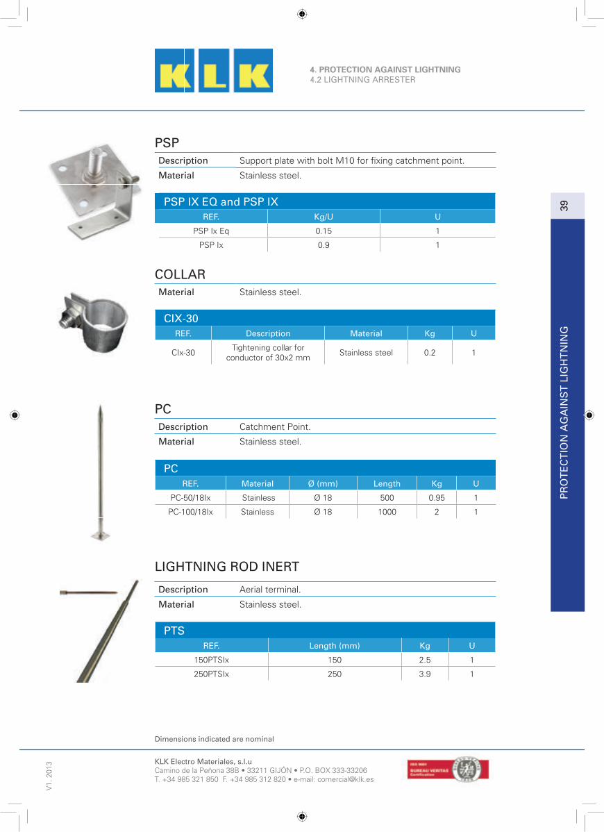
PSPDescription Support plate with bolt M10 for fi xing catchment point.
Material Stainless steel.
PSP IX EQ and PSP IXREF. Kg/U U
PSP Ix Eq 0.15 1
PSP Ix 0.9 1
COLLARMaterial Stainless steel.
CIX-30REF. Description Material Kg U
CIx-30Tightening collar for
conductor of 30x2 mmStainless steel 0.2 1
PCDescription Catchment Point.
Material Stainless steel.
PCREF. Material Ø (mm) Length Kg U
PC-50/18Ix Stainless Ø 18 500 0.95 1
PC-100/18Ix Stainless Ø 18 1000 2 1
LIGHTNING ROD INERT
Description Aerial terminal.
Material Stainless steel.
PTSREF. Length (mm) Kg U
150PTSIx 150 2.5 1
250PTSIx 250 3.9 1

KLK Electro Materiales, s.l.uCamino de la Peñona 38B • 33211 GIJÓN • P.O. BOX 333-33206T. +34 985 321 850 F. +34 985 312 820 • e-mail: [email protected]
Dimensions indicated are nominal
V1.
201
3P
RO
TE
CT
ION
AG
AIN
ST
LIG
HT
NIN
G40
4. PROTECTION AGAINST LIGHTNING4.3 SUPPORTS
PDC and PS-AGDescription Fixing support to be embedded or screwed to wall.
Material Galvanised steel.
PDD-24 AG and PB-13 AGDescription Fixing support.
CXD-AG and CX-AG y CK-AGDescription Double clamp anchoring in parallel.
Material Galvanised steel.
REF. Ø (mm) Length (mm) Kg U
PDC 20 AG-H Ø 22 to 55 200 1,5 1
PDC 20 AG-V Ø 22 to 55 200 1,5 1
PDC 30 AG-H Ø 22 to 55 300 2 1
PDC 30 AG-V Ø 22 to 55 300 2 1
PS-AG Ø 22 to 55 300 1,5 1
PDD-24 AG Ø 22 to 55 240 1,5 1
PB-13AG Ø 22 to 55 130 1 1
CXD-AG Ø 22 to 55 -- 0,5 1
CX-AG Ø 22 to 55 -- 0,5 1
CK-AG Ø 22 to 55 -- 0,5 1

KLK Electro Materiales, s.l.uCamino de la Peñona 38B • 33211 GIJÓN • P.O. BOX 333-33206T. +34 985 321 850 F. +34 985 312 820 • e-mail: [email protected]
Dimensions indicated are nominal
4. PROTECTION AGAINST LIGHTNING4.3 SUPPORTS
PR
OT
EC
TIO
N A
GA
INS
T L
IGH
TN
ING
V1.
201
3
41
PROTECTION AGAINST LIGHTNINGDescription Aimed at uniting the mast of the antenna to the lightning
arrester to ensure the equipotential union between themetal elements.
Material Stainless steel.
Designation Nominal discharge current (8/20 µs): 25kAa.c. Spark over voltage (50 Hz): 10 kVStriking voltage at 100% to the shock wave (1.2/50 µs): 25kA.
E-MAT ANTENNE
REF. Dimension (mm)
Distancebetween axes
(mm)
DimensionHoles (mm) Kg U
E-MAT ANTENNE 30 x 3.5 115 11 x 13 0.26 1
SIGNAGE PLATEDescription Signage plate in Spanish, English or French: Earthing.
Material Aluminium.
Dimensions 10 x 10 x 10 cm.
Weight 110 g.
SIGNAGE PLATE

KLK Electro Materiales, s.l.uCamino de la Peñona 38B • 33211 GIJÓN • P.O. BOX 333-33206T. +34 985 321 850 F. +34 985 312 820 • e-mail: [email protected]
Dimensions indicated are nominal
V1.
201
3P
RO
TE
CT
ION
AG
AIN
ST
LIG
HT
NIN
G42
4. PROTECTION AGAINST LIGHTNING4.4 ACCESSORIES FOR DOWN PIPES
CLAMP FOR FLAT / ROUND CONDUCTORDescription Brass connection terminal made by hot-stamping for fl at or
round conductor.For bolt M6 DIN 912 .
Material Copper-rich alloy (Brass).
BC-30/8REF. Length (L: mm) Capacity (mm) Kg/U U
BC 30-8 7030x2 - 30x3.5
Ø6 - Ø80.40 1
FP-30/2 Y FP-30/2IXDescription Protection for fl at conductor of up to 30x4 mm
supplied with 3 fi xings.
Material Protection: Galvanised steel / Stainless steelFixings: Stainless steel.
FP-30/2 and FP-30/2IXREF. Length (mm) Kg/U U
FP-30/2 2000 1.2 1
FP-30/2Ix 2000 1.2 1
DIGITAL METER CTR-8EDescription Digital Meter which allows counting the lightning discharges
at an outdoor lightning protection installation. The digitalscreen enables directly reading the amount of impactsrecorded. The recording of the lightning discharges and theirmemorisation does not need any exterior power supply, so itdoes not depend on the duration of the battery. Only the digital screen, directed by a front button requires a power supplied by a long-lasting lithium battery.
Installation Installed directly on the down conductor.No interruption of the conductor is required which allows anexcellent electrical continuity from the point to the earhting.The meter records the lightning power when it passes through the down conductor.
Characteristics Meter conforming to standard UTE C17106Minimum detection power(Id) > = 1 kAMaximum power detection (Imax.) < = 100 kALack of detection power (Ind) = Id / 3 = 333 AProtection indexes IP 54

KLK Electro Materiales, s.l.uCamino de la Peñona 38B • 33211 GIJÓN • P.O. BOX 333-33206T. +34 985 321 850 F. +34 985 312 820 • e-mail: [email protected]
Dimensions indicated are nominal
4. PROTECTION AGAINST LIGHTNING4.4 ACCESSORIES FOR DOWN PIPES
PR
OT
EC
TIO
N A
GA
INS
T L
IGH
TN
ING
V1.
201
3
43
METER CTR-8Description Meter with mechanical indicator which allows counting the
lightning discharges at an outdoor lightning protection installation.
Characteristics Meter conforming Standard UTE C-17-106Minimum detection power (Id) > = 0,7 kAMaximum detection power (Imax.) < = 100 kAProtection indexes IP 65
METER CTR-8SADescription Digital Meter which allows counting the lightning discharges
of an intensity between 1 kA and 100 kA. This meter isconnected in siries with a round conductor of 8 to 10 mmdiameter or bus-bar of 30x2.
Characteristics Conforming Directive CEMSensitivity: 200A (8/20 µs)Minimum detection power (Id) > = 0,7 kAMaximum detection power (Imax.) < = 100 kA (8/20 µs)Protection index: IP 65
SWITCH BOXDescription Box made of insulating material which includes a switch
used to check the earhting resistance in the transformerstations.
Material Housing: resistant polycarbonate at 960ºC.Connections: Electrolytic tin copper of 20x3 mm.Connection terminals: CFeedthrough cones: PVC

KLK Electro Materiales, s.l.uCamino de la Peñona 38B • 33211 GIJÓN • P.O. BOX 333-33206T. +34 985 321 850 F. +34 985 312 820 • e-mail: [email protected]
Dimensions indicated are nominal
4. PROTECTION AGAINST LIGHTNING4.4 ACCESSORIES FOR DOWN PIPES
V1.
201
3P
RO
TE
CT
ION
AG
AIN
ST
LIG
HT
NIN
G44
DISCONNECTING LINKDescription Disconnecting link for round conductor.
Characteristics Body: Plastic. Hardware: Brass.
BCTREF. Dimensions (mm) Section Cable (mm²) Kg/U U
BCT-35 125x30x26 25-35 0.12 10
BCT-70 150x34x65 35-70 0.27 10
BCTI-50 150x45x70 25-50 0.31 5
TEST LINKSDescription Test link for the disconnection of the underground power
from the aerial and perform the correct measurement ofthe Earthing Resistance. Formed by three copper busbarsfi xed with two hexagonal screws.The fi xing to the support is not included in the supply.
Material Test link: Electrogalvanised copper bus-bar.Hardware: Electrogalvanised brass with variant in stainlesssteel.
PTType Dimensions Bus-Bar (mm) Section conductor Cable Max(mm²)
PT-3 25 x 3 75 0.29
PT-4 25 x 4 100 0.38
PT-5 25 x 5 125 0.45
PT-6 25 x 6 150 0.55

KLK Electro Materiales, s.l.uCamino de la Peñona 38B • 33211 GIJÓN • P.O. BOX 333-33206T. +34 985 321 850 F. +34 985 312 820 • e-mail: [email protected]
Dimensions indicated are nominal
EQ
UIP
OT
EN
TIA
L LI
NK
S
V1.
201
3
45
5. EQUIPOTENTIAL LINKS5.1 SOLID COPPER SLOTTED ANDTHREADED BARS
SLOTTED AND THREADED BARSDescription Slotted and threaded bars.
Material Copper.
CREF. Size (mm) Diameter (mm) A (mm) Kg/m U
Plain hole, Length 1750 mm Double
C-1750/25x5/10 25x5x1750 10.5 25 1.66 1
Double holes, Length 1750 mm
C-1750/50x5/10 50x5x1750 10.5 25 3.32 1
C-1750/80x5/10 80x5x1750 10.5 25 5.30 1
C-1750/100x5/10 100x5x1750 10.5 25 6.64 1
Threaded hole, Length 1000
C-1000/18x4/M8 18x4x1000 8 25 0.64 1
C-1000/30x10/M8 30x10x1000 8 25 2.67 1
Threaded hole, Length 990
C-990/12x4/M5 12x4x990 5 25 0.36 1
C-990/20x5/M6 20x5x990 6 25 0.76 1
C-990/32x5/M6 32x5x990 6 25 1.22 1
Plain hole
C-280-6-8 50x5x280 8.5 35 0.63 1
C-420-10-8 50x5x420 8.5 35 0.94 1
C-595-15-8 50x5x595 8.5 35 1.32 1
C-770-20-8 50x5x770 8.5 35 1.71 1
C-945/25/8 50x5x945 8.5 35 2.10 1
Double hole, Length 300
C-300/100x10/10 100x10x300 10.5 30 2.67 1
* Other dimensions upon request.
COPPER BARSDescription Copper bars.
Material Copper.
CREF. Size (mm) Kg/m ml
C25x3 25x3 0.668 3
C25x5 25x5 1.112 3
C40x5 40x5 1.780 3
C50x5 50x5 2.225 3
C80x5 80x5 3.56 3
C100x5 100x5 4.45 3
C100x10 100x10 8.90 3
* Other dimensions upon request.
C

KLK Electro Materiales, s.l.uCamino de la Peñona 38B • 33211 GIJÓN • P.O. BOX 333-33206T. +34 985 321 850 F. +34 985 312 820 • e-mail: [email protected]
Dimensions indicated are nominal
V1.
201
3E
QU
IPO
TE
NT
IAL
LIN
KS
46
5. EQUIPONTENTIAL LINKS5.2 EQUIPOTENTIALITY BARS
EARTHING BARSDescription Equipotentiality bar. Slotted for 6-10-15-20-25
connections on copper bus-bar of 50x5. Mounted withinsulators on perforated profi le for an easy fi xing.
Material Bar: copper. Insulators: fi breglass - polyester.
BEREF. Length (mm) Number of holes (mm) Kg/U U
BE-280/6/8 280 6 1.25 1
BE-420/10/8 420 10 1.75 1
BE-595/15/8 595 15 2.25 1
BE-770/20/8 770 20 2.80 1
BE-945/25/8 945 25 3.35 1
EARTHING BARSDescription Perforated bus-bar with or without insulators.
Material Copper.
C-300/100X10/10 and BC-300/100X10/10REF. Length (mm) Number of holes Kg/U U
BE-300/100x10/10 300 2x10 3 1
EARTHING BARS WITH DISCONNECTING LINKDescription Equipotentiality bar with incorporated disconnecting link.
Perforated for 6-10-15-20-25 connections on copper bus-barof 50x5.Mounting with insulators on perforated profi le for an easy fi xing.
Material Bar: Copper. Insulators: Fibreglass - Polyester.
BCEREF. Length (mm) Number of holes (mm) Kg/U U
BEC-280/6/8 350 6 1.65 1
BEC-420/10/8 490 10 2.15 1
BEC-595/15/8 665 15 2.65 1
BEC-770/20/8 770 20 3.20 1
BEC-945/25/8 1015 25 3.75 1

KLK Electro Materiales, s.l.uCamino de la Peñona 38B • 33211 GIJÓN • P.O. BOX 333-33206T. +34 985 321 850 F. +34 985 312 820 • e-mail: [email protected]
Dimensions indicated are nominal
EQ
UIP
OT
EN
TIA
L LI
NK
S
5. EQUIPONTENTIAL LINKS5.2 EQUIPOTENTIALITY BARS
V1.
201
3
47
DISCONNECTING LINKDescription Copper bus-bar disconnecting link of 50x5, mounted on
clamping profi le.
Material Bar: Copper. Insulators: fi breglass- Polyester.
BC-200/3/8REF. Length (mm) Kg/U U
BC-200/3/8 110 0.70 1
FIBREGLASS –POLYESTER INSULATORSDescription Insulators with high mechanical resistance and
high electrical properties. They can be used inunfavourable environmental conditions.
Material Fibreglass - Polyester.
ISO-FFREF. Nominal Voltage (V) Height H: mm C: M x mm Kg/U U
ISO-35FFM6 750 35 M6 x 10 0.10 50
ISO-35FFM8 750 35 M8 x 10 0.10 50
ISO-50FFM8 1500 50 M8 x 15 0.20 50
ISO-50FFM10 1500 50 M10 x 15 0.20 50
ISO-80FFM12 3600 80 M12 x 25 0.25 25

KLK Electro Materiales, s.l.uCamino de la Peñona 38B • 33211 GIJÓN • P.O. BOX 333-33206T. +34 985 321 850 F. +34 985 312 820 • e-mail: [email protected]
Dimensions indicated are nominal
5. EQUIPONTENTIAL LINKS5.2 EQUIPOTENTIALITY BARS
V1.
201
3E
QU
IPO
TE
NT
IAL
LIN
KS
48
EARTHING BARSDescription Equipotentiality earthing bar to mount on concrete formed
by a copper bus-bar with KBH type clamps to connect the cables from the different circuits of the aerial earhting network.
Material Equipotentiality bus-bar: electrogalvanised copper.Clamps:- Body: Copper-rich alloy (Brass).- Hardware: Electrogalvanised copper with variant inStainless steel.Fixings: Electrogalvanised steel.
For earthing bars with more clamps or combined upon request.
EC
REF. Nº. ofClamps
Section ConductorCable mm²
Amm
Bmm
Cmm D Kg/U
EC 70-2 2
25 70 60
195
6
170 1.15
EC 70-3 3 265 240 1.55
EC 70-4 4 335 310 2
EC 70-5 5 405 380 2.45
EC 70-6 6 475 450 2.91
EC 100-2 2
70 95 60
195
6
170 1.23
EC 100-3 3 265 240 1.67
EC 100-4 4 335 310 2.13
EC 100-5 5 405 380 2.65
EC 100-6 6 475 450 3.16
EC 200-2 2
95 185 60
195
6
170 1.8
EC 200-3 3 265 240 2.51
EC 200-4 4 335 310 3.25
EC 200-5 5 405 380 4.05
EC 200-6 6 475 450 4.86

KLK Electro Materiales, s.l.uCamino de la Peñona 38B • 33211 GIJÓN • P.O. BOX 333-33206T. +34 985 321 850 F. +34 985 312 820 • e-mail: [email protected]
Dimensions indicated are nominal
EQ
UIP
OT
EN
TIA
L LI
NK
S
V1.
201
3
49
5. EQUIPOTENTIAL LINKS5.3 FLANGES
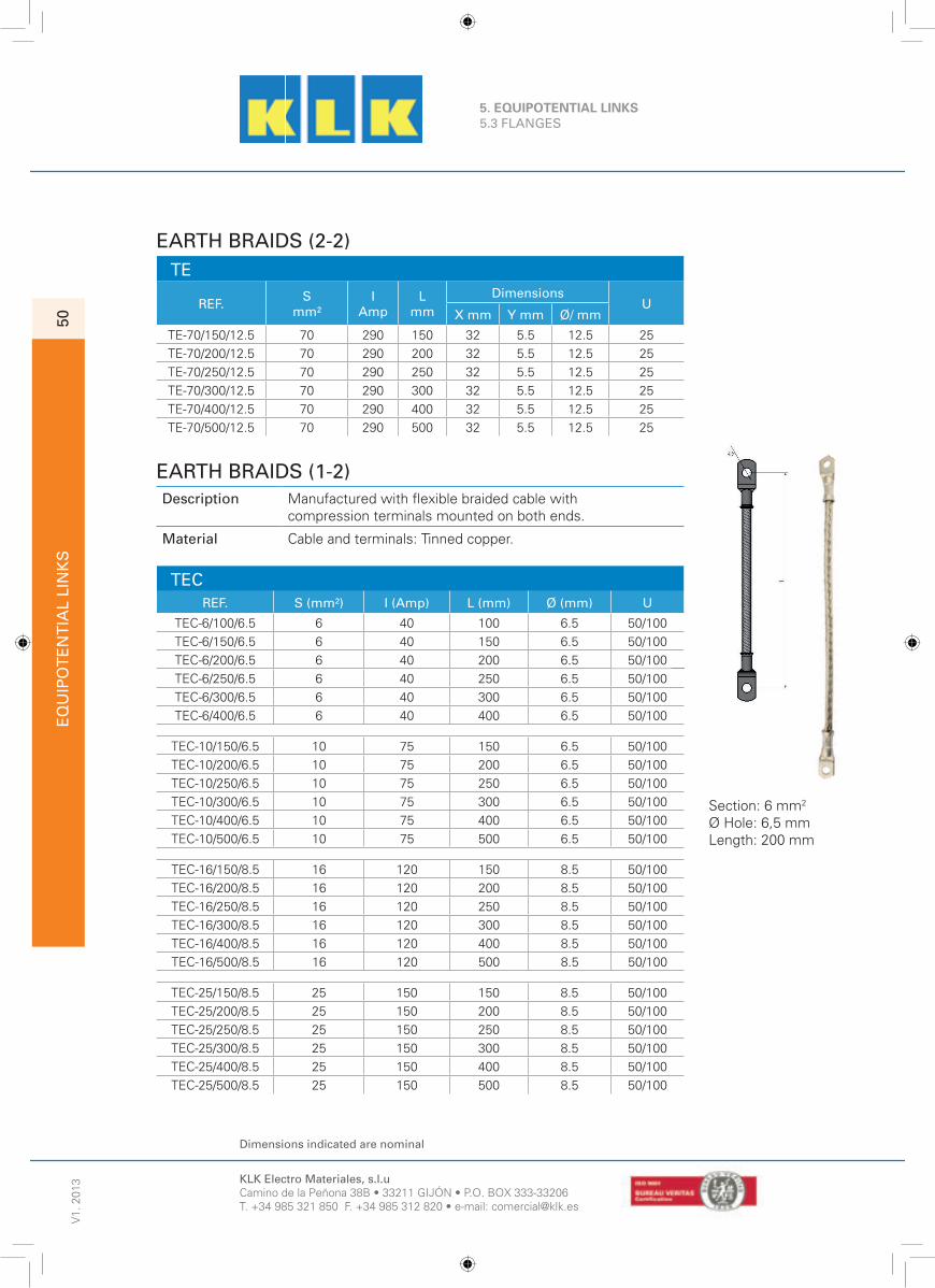
EARTH BRAIDS (1-2)Description Manufactured with fl at copper braid and with fl at tabs on
both ends.
Material Tinned copper.
TE
REF. S mm²
IAmp
Lmm
DimensionsU
X mm Y mm Ø/ mm
TE-10/100/6.5 10 75 100 14 3.5 6.5 50/100
TE-10/150/6.5 10 75 150 14 3.5 6.5 50/100
TE-10/200/6.5 10 75 200 14 3.5 6.5 50/100
TE-10/250/6.5 10 75 250 14 3.5 6.5 50/100
TE-10/300/6.5 10 75 300 14 3.5 6.5 50/100
TE-16/100/8.5 16 120 100 17 4 8.5 50/100
TE-16/150/8.5 16 120 150 17 4 8.5 50/100
TE-16/200/8.5 16 120 200 17 4 8.5 50/100
TE-16/250/8.5 16 120 250 17 4 8.5 50/100
TE-16/300/8.5 16 120 300 17 4 8.5 50/100
TE-16/350/8.5 16 120 350 17 4 8.5 50/100
TE-16/400/8.5 16 120 400 17 4 8.5 50/100
TE-25/100/8.5 25 150 100 23 4 8.5 25/50
TE-25/150/8.5 25 150 150 23 4 8.5 25/50
TE-25/200/8.5 25 150 200 23 4 8.5 25/50
TE-25/250/8.5 25 150 250 23 4 8.5 25/50
TE-25/300/8.5 25 150 300 23 4 8.5 25/50
TE-25/350/8.5 25 150 350 23 4 8.5 25/50
TE-25/400/8.5 25 150 400 23 4 8.5 25/50
TE-35/100/10.5 35 190 100 27 4.2 10.5 25/50
TE-35/150/10.5 35 190 150 27 4.2 10.5 25/50
TE-35/200/10.5 35 190 200 27 4.2 10.5 25/50
TE-35/250/10.5 35 190 250 27 4.2 10.5 25/50
TE-35/300/10.5 35 190 300 27 4.2 10.5 25/50
TE-35/350/10.5 35 190 350 27 4.2 10.5 25/50
TE-35/400/10.5 35 190 400 27 4.2 10.5 25/50
TE-50/100/10.5 50 250 100 33 5 10.5 25
TE-50/150/10.5 50 250 150 33 5 10.5 25
TE-50/200/10.5 50 250 200 33 5 10.5 25
TE-50/250/10.5 50 250 250 33 5 10.5 25
TE-50/300/10.5 50 250 300 33 5 10.5 25
TE-50/350/10.5 50 250 350 33 5 10.5 25
TE-50/400/10.5 50 250 400 33 5 10.5 25
TE-50/500/10.5 50 250 500 33 5 10.5 25
Description
Material
TE
Section: 25 mm2Ø Hole: 8,5 mmLength: 300 mm
KLK Electro Materiales, s.l.uCamino de la Peñona 38B • 33211 GIJÓN • P.O. BOX 333-33206T. +34 985 321 850 F. +34 985 312 820 • e-mail: [email protected]
Dimensions indicated are nominal
5. EQUIPOTENTIAL LINKS5.3 FLANGES
V1.
201
3E
QU
IPO
TE
NT
IAL
LIN
KS
50
EARTH BRAIDS (2-2) TE
REF. S mm²
IAmp
Lmm
DimensionsU
X mm Y mm Ø/ mm
TE-70/150/12.5 70 290 150 32 5.5 12.5 25
TE-70/200/12.5 70 290 200 32 5.5 12.5 25
TE-70/250/12.5 70 290 250 32 5.5 12.5 25
TE-70/300/12.5 70 290 300 32 5.5 12.5 25
TE-70/400/12.5 70 290 400 32 5.5 12.5 25
TE-70/500/12.5 70 290 500 32 5.5 12.5 25
EARTH BRAIDS (1-2)Description Manufactured with fl exible braided cable with
compression terminals mounted on both ends.
Material Cable and terminals: Tinned copper.
TECREF. S (mm²) I (Amp) L (mm) Ø (mm) U
TEC-6/100/6.5 6 40 100 6.5 50/100
TEC-6/150/6.5 6 40 150 6.5 50/100
TEC-6/200/6.5 6 40 200 6.5 50/100
TEC-6/250/6.5 6 40 250 6.5 50/100
TEC-6/300/6.5 6 40 300 6.5 50/100
TEC-6/400/6.5 6 40 400 6.5 50/100
TEC-10/150/6.5 10 75 150 6.5 50/100
TEC-10/200/6.5 10 75 200 6.5 50/100
TEC-10/250/6.5 10 75 250 6.5 50/100
TEC-10/300/6.5 10 75 300 6.5 50/100
TEC-10/400/6.5 10 75 400 6.5 50/100
TEC-10/500/6.5 10 75 500 6.5 50/100
TEC-16/150/8.5 16 120 150 8.5 50/100
TEC-16/200/8.5 16 120 200 8.5 50/100
TEC-16/250/8.5 16 120 250 8.5 50/100
TEC-16/300/8.5 16 120 300 8.5 50/100
TEC-16/400/8.5 16 120 400 8.5 50/100
TEC-16/500/8.5 16 120 500 8.5 50/100
TEC-25/150/8.5 25 150 150 8.5 50/100
TEC-25/200/8.5 25 150 200 8.5 50/100
TEC-25/250/8.5 25 150 250 8.5 50/100
TEC-25/300/8.5 25 150 300 8.5 50/100
TEC-25/400/8.5 25 150 400 8.5 50/100
TEC-25/500/8.5 25 150 500 8.5 50/100
Section: 6 mm2
Ø Hole: 6,5 mmLength: 200 mm

KLK Electro Materiales, s.l.uCamino de la Peñona 38B • 33211 GIJÓN • P.O. BOX 333-33206T. +34 985 321 850 F. +34 985 312 820 • e-mail: [email protected]
Dimensions indicated are nominals
EQ
UIP
OT
EN
TIA
L LI
NK
S
5. EQUIPOTENTIAL LINKS5.4 CLAMPING RINGS
V1.
201
3
51
PIPE SUPPORTDescription Strip coil to fasten and fi x to pipe.
Material Stainless steel.
F-REF. Dimensions (mm) Kg U (m)
F104 10 x 0.4 1.80 50
F107 10 x 0.7 3.00 50
F204 20 x 0.4 3.50 50
F207 20 x 0.7 5.90 50
SUPPORTDescription Clamp (holding clip) for 10 mm wide tape
Material Stainless steel.
A-REF. Length (mm) Kg / 100 U
A 100 10 0.36 100
A 200 20 0.60 100
CLAMPSDescription OPL.
Material Tool to tighten strip of 10 to 20 mm wide.

KLK Electro Materiales, s.l.uCamino de la Peñona 38B • 33211 GIJÓN • P.O. BOX 333-33206T. +34 985 321 850 F. +34 985 312 820 • e-mail: [email protected]
Dimensions indicated are nominal
V1.
201
3C
ON
DU
CT
OR
S52
6. CONDUCTORS6.1 CONDUCTORS
INSULATED COPPER CONDUCTORDescription Insulated copper conductor green, yellow.
Material Copper.
H07-V
REF. Section (mm²) Composition(nº wires x Ø mm) Kg/m ml
H07-VK-1x6 6 84x0.31 0.06 100 & coil
H07-VR-1x6 6 7x1.04 0.07 100 & coil
H07-VK-1x10 10 80x0.41 0.10 100 & coil
H07-VR-1x10 10 7x1.35 0.11 100 & coil
H07-VK-1x16 16 126x0.41 0.16 100 & coil
H07-VR-1x16 16 7x1.70 0.16 100 & coil
H07-VK-1x25 25 196x0.41 0.25 100 & coil
H07-VR-1x25 25 7x2.14 0.26 100 & coil
H07-VK-1x35 35 276x0.41 0.34 100 & coil
H07-VR-1x35 35 7x2.52 0.36 100 & coil
H07-VK-1x50 50 396x0.41 0.46 50 & coil
H07-VR-1x50 50 19x1.78 0.48 50 & coil
H07-VK-1x70 70 360x0.51 0.68 coil
H07-VR-1x70 70 19x2.14 0.74 coil
H07-VK-1x95 95 475x0.51 0.954 coil
H07-VR-1x95 95 19x2.52 0.96 coil
H07-VK-1x120 120 608x0.51 1.20 coil
H07-VR-1x120 120 37x2.03 1.152 coil

KLK Electro Materiales, s.l.uCamino de la Peñona 38B • 33211 GIJÓN • P.O. BOX 333-33206T. +34 985 321 850 F. +34 985 312 820 • e-mail: [email protected]
Dimensiones indicated are nominal
CO
ND
UC
TO
RS
V1.
201
3
53
6. CONDUCTORS6.2 ROUND CONDUCTORS
ROUND SOLID CONDUCTORDescription Round solid conductor.
Material See table.
RDREF. Diameter (Ø mm) Material Kg/m ml
RD-6 6 Pure Copper 0.25 100-120
RD-8 8 Pure Copper 0.448 50-60
RD-8/E 8 Tin copper 0.448 50-60
RD-8/3 8 Pure Copper 0.448 3
RD-8AG 8 Galvanised steel 0.393 100-130
RD-8Ix 8 Stainless steel 0.9 90-110
RD-10AG 10 Galvanised steel 0.617 50-80
RD-10 Ix 10 Stainless steel 0.625 50-80
RD-8Al 8 Aluminium 0.135 150
RD-10Al 10 Aluminium 0.21 100

KLK Electro Materiales, s.l.uCamino de la Peñona 38B • 33211 GIJÓN • P.O. BOX 333-33206T. +34 985 321 850 F. +34 985 312 820 • e-mail: [email protected]
Dimensions indicated are nominal
V1.
201
3C
ON
DU
CT
OR
S54
6. CONDUCTORS6.3 FLAT CONDUCTORS
FLAT CONDUCTORDescription CE.
Material Flat conductor.
CE-AI-AGREF. Size (mm) Material Kg/m ml
CE-27x2 27x2 Tinned copper 0.480 50
CE-30x2 30x2 Tinned copper 0.534 60
AI-30x3,5 V2A 30x3,5 Stainless steel 304 0.83 60
AI-30x3,5 V4A 30x3.5 Stainless steel 316 0.83 60
ALU-30x3 30x3 Aluminium 0.243 110
AG70-30x3,5 30x3,5 Galvanised steel (70 µm) 0.84 50
* Other dimensions upon request.

KLK Electro Materiales, s.l.uCamino de la Peñona 38B • 33211 GIJÓN • P.O. BOX 333-33206T. +34 985 321 850 F. +34 985 312 820 • e-mail: [email protected]
Dimension indicated are nominal
CO
ND
UC
TO
RS
V1.
201
3
55
6. CONDUCTORS6.4 Cu and Ag CONDUCTORS
COPPER CONDUCTORS
Description Braided conductor.
Material Copper.
CRR
REF. Section (mm²) Composition(nº wires x Ø mm) g/m ml
CRR-16 16 7 x 1.71 0.144 50/100/coil
CRR-25 25 7 x 2.13 0.225 50/100/coil
CRR-29 29 19 x 1.40 0.267 50/100/coil
CRR-35 35 7 x 2.50 0.305 50/100/coil
CRR-50 50 19 x 1.77 0.42 25/50/coil
CRR-70 70 19 x 2.14 0.6 25/50/coil
CRR-95 95 19 x 2.52 0.83 25/50/coil
CRR-120 120 19 x 2.94 1.040 coil
CRR-120/37 120 37 x 2.05 1.065 coil
CRR-150 150 19 x 3.24 1.26 coil
CRR-150/37 150 37 x 2.21 1.26 coil
CRR-185 185 37 x 2.50 1.62 coil
CRR-240 240 61 x 2.28 2.20 coil
CRR-300 300 61 x 2.50 2.65 coil
STEEL CONDUCTORSDescription Conductor.
Material Hot-Galvanised steel.
CAGREF. Section (mm²) Composition (nºhilos) Kg/m ml
CAG-50/50 50 19 0.46 coil
CAG-70/50 70 19 0.60 coil
CAG-95/50 95 19 0.80 coil
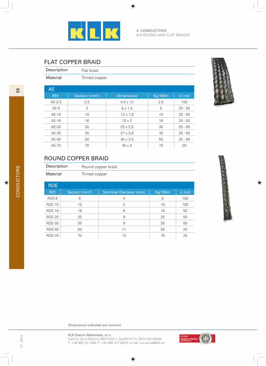
KLK Electro Materiales, s.l.uCamino de la Peñona 38B • 33211 GIJÓN • P.O. BOX 333-33206T. +34 985 321 850 F. +34 985 312 820 • e-mail: [email protected]
Dimensions indicated are nominal
V1.
201
3C
ON
DU
CT
OR
S56
6. CONDUCTORS6.5 ROUND AND FLAT BRAIDS
FLAT COPPER BRAIDDescription Flat braid.
Material Tinned copper.
AEREF. Section (mm²) Dimensions Kg/100m U (ml)
AE-2,5 2,5 4.5 x 13 2,5 100
AE-5 5 8 x 1,4 5 25 - 50
AE-10 10 12 x 1,8 10 25 - 50
AE-16 16 15 x 2 16 25 - 50
AE-30 30 25 x 2,5 30 25 - 50
AE-35 35 27 x 2,8 35 25 - 50
AE-50 50 30 x 3,5 50 25 - 50
AE-70 70 30 x 5 70 25
ROUND COPPER BRAIDDescription Round copper braid.
Material Tinned copper.
RDEREF. Section (mm²) Nominal Diameter (mm) Kg/100m U (ml)
RDE-6 6 4 6 100
RDE-10 10 5 10 100
RDE-16 16 6 16 50
RDE-25 25 8 25 50
RDE-35 35 9 35 50
RDE-50 50 11 50 25
RDE-70 70 13 70 25

KLK Electro Materiales, s.l.uCamino de la Peñona 38B • 33211 GIJÓN • P.O. BOX 333-33206T. +34 985 321 850 F. +34 985 312 820 • e-mail: [email protected]
Dimensions indicated are nominal
CO
ND
UC
TO
RS
6. CONDUCTORS6.5 ROUND AND FLAT BRAIDS
V1.
201
3
57
FLAT COPPER BRAIDDescription Flat copper braid with PVC coating.
Material Body: Tin copper. Coating: PVC.
AE-PVCREF. Section (mm²) Dimensions (mm) Kg/100m U (ml)
AE-10PVC 10 12 x 3,5 15 50
AE-16PVC 16 17 x 3,5 23 50
AE-25PVC 25 27 x 4 35 50
AE-35PVC 35 29 x 4 46 50
AE-50PVC 50 28 x 7 65 50
AE-70PVC 70 30 x 5 95 25
ROUND COPPER BRAIDDescription Round braid.
Material Body: Tin copper. Coating: PVC.
RDE-PVCREF. Section (mm²) Dimensions (mm) Kg/100m U
RDE-10PVC 10 7 13 50
RDE-16PVC 16 8 19 50
RDE-25PVC 25 10 35 50
RDE-35PVC 35 12 53 50
RDE-50PVC 50 13 71 50

7. COPPER ALUMINOTHERMIC WELDING
KLK-WELD PROCEDURE
The KLK-WELD process utilizes the high temperature of the reaction between copper oxide and aluminium. The reaction takes place in a graphite mould-crucible, into which the pieces to be welded have been inserted; the melted metal from the aluminothermic reaction fl ows over the pieces, causing them to melt and fuse into a solid homogeneous mass.
The reaction is so quick that the pieces to be welded get a lower temperature, on the zone around the welding point, than that arising when using other process. This is an important fact for protecting insulated cables or the physical characteristics of the pieces to be welded.
The KLK-WELD process may also be used in addition to welding copper to
copper,Eg. connections between copper and other materials.
C
KLK-WELD CONNECTION
The KLK-WELD connection is a perfect molecular weld and not just a mechanical contact. The alloy used has practically the same fusion temperature as that of copper and usually has a section double than that of the conductors to be welded, therefore:
· Connections are not affected by high current surges. Tests have shown that the electrical conductors will melt before the connection when subject to high short-circuit current.
· Connection conductivity is at least equal or greater than the conductors welded.
· There is no possibility of corrosion at the point of the weld, since the conductors become an integral part of the connection.
CO
PP
ER
ALU
MIN
OT
HE
RM
IC W
ELD
ING
58

CO
PP
ER
ALU
MIN
OT
HE
RM
IC W
ELD
ING
7. COPPER ALUMINOTHERMIC WELDING
59
KLK-WELD MOULD
KLK-WELD CARTRIDGES AND DISCS
Each plastic container holds the aluminothermic powder at one end (coloured cover)and the starting powder at the other one (black cover). The disc is used to seal the tap hole before depositing the load.
Mould cover
Starting powder
Aluminothermic powder
Metallic disc
Tap hole
Welding cavity
Lower cover, black coloured
Starting powder
Aluminothermic powder
Upper cover, coloured according to cartridge size
Cables
CARTRIDGE C-15 C-25 C-32 C-45 C-65 C-90 C-115 C-150 C-200 C-250
COLOUR LIGHT GREY GREY PURPLE WHITE YELLOW ORANGE RED BROWN BLUE GREEN
UNITS/BOX 20 20 20 20 10 10 10 10 10 10

7. COPPER ALUMINOTHERMIC WELDING
CO
PP
ER
ALU
MIN
OT
HE
RM
IC W
ELD
ING
60
KLK-WELD EQUIPMENT
The KLK-WELD equipment is light and portable and requires no outside power source, this being useful for fi eld use. It requires very little time or skill to get top quality connections.
MOULDS:
The moulds are manu-factured from a heat-re-sistant material (graphi-te) block that lasts for an average of 70-100 con-nections under normal conditions of use.
The metallic cover pro-tects from the reaction projections.
FLINT IGNITER:
Used to ignite the igni-tion powder. It takes nor-mal lighter fl ints as spare parts.
HANDLE CLAMPS TSC:
CARDCLOTH BRUSH:
MOULD BRUSH:
They are designed to handle the moulds allowing to open and clo-se them safely.
There are three types of handle clamps depen-ding on the Mould size: TSC 50, TSC-80 and TSC-100.
Used for the correct clea-ning of cables to welded.
For cleaning the interior of the mould after each weld.
HANDLE CLAMP MS:
It is designed to fi t Moulds manufactured from a so-lid piece of graphite, spe-cially those used to weld steel pieces.
MOULD SCRAPER:
Its shape is specially de-signed to clean the mould loading hopper.

CO
PP
ER
ALU
MIN
OT
HE
RM
IC W
ELD
ING
7. COPPER ALUMINOTHERMIC WELDING
61
TABLES OF CABLES, BUS-BARS AND EARTH RODS
The moulds are cut to fi t the type and size of copper conductors, concrete steel re-bars and earth rods shown on these tables. For any other type and/or size, it is necessary to confi rm the actual overall diameter.
SECTION mm² COMPOSITION Ø EXTERIOR mm.
10 7 x 1,35 4,05
16 7 x 1,70 5,10
25 7 x 2,14 6,42
35 7 x 2,52 7,56
50 19 x 1,83 9,15
70 19 x 2,17 10,85
95 19 x 2,52 12,60
120 19 x 2,85 14,25
150 37 x 2,25 15,75
185 37 x 2,52 17,64
235 37 x 2,85 19,95
300 61 x 2,62 22,68
400 61 x 2,85 25,65
COPPER CONDUCTORS (UNE 21012)
COPPER-STEEL EARHT RODS CONCRETE STEEL RE-BARSEARTH ROD TYPE Ø EXTERIOR mm.
J - ...58 14,3
J - ...34 17,3
...NU 146 14,6
...NU 183 18,3
...ST 143 14,3
Ø NOMINAL Ø EXTERIOR mm.
6 7,2
8 9,6
10 12,0
12 14,4
14 16,8
16 192
20 24,0
25 30,0

7. COPPER ALUMINOTHERMIC WELDING
PREPARATION OF MATERIAL
PREPARATION OF THE CABLES
To achieve a perfect weld the cable must be clean, dry and well fi tting.
Cables treated with oil or grease must be cleaned with a degreaser (preferably a quick drying and non residual solvent). In extreme cases heat the conductor with a welding torch to remove grease and oil completely.
Rusty cables must be polished with a cardclothbrush.
A moist or muddy conductor will cause a porous weld and molten metal outside the mould. Conductors must be dried with a welding torch and then all mud removed.
Badly-cut or fi tted conductors will prevent the mould from closing properly, causing molten metal to spill.PREPARACIÓN DE LAS PICAS DE PUESTA A TIERRA
PREPARATION OF THE STEEL SURFACES
Steel surface must be rust free and perfectly clean and fl at.
· Rust fi lm, paint, grease or dust must be cleaned off with a grinder.
· Remove moisture with a welding torch.
· Galvanized surfaces may be cleaned without needing to remove the zinc coating.
CO
PP
ER
ALU
MIN
OT
HE
RM
IC W
ELD
ING
62
PREPARATION OF THE EARTH RODS
Earth rod end on which the weld is to be done must be perfectly clean, dry and without any deformation.
PREPARATION OF THE GRAPHITE MOULD
Moisture in moulds will cause a porous weld. Moulds must be perfectly dry before making a weld.
For making proper coneections, warm the mould before starting the fi rst weld with a welding torch or ignite a cartridge to get the mould over 100º C. When using a cartridge be careful to avoid handle clamp damage due to molten metal leaking.
Generated heat will maintain the mould at the appropiate temperature for the next weld. If delays among welds cause temperature to fall the mould drying process must be started again.

CO
PP
ER
ALU
MIN
OT
HE
RM
IC W
ELD
ING
7. COPPER ALUMINOTHERMIC WELDING
63
Remove the insulation-
from the cable on a length of 15 cm. when using in-sulated cable. Using the cardclothbrush brush the cable and the rod end to remove all the dust and oxides.
Before starting the fi rst weld pre-heat the graphi-te mould which the wel-ding torch during at least 5 minutes. This operation is very important because moisture in moulds will cause a porous weld.
Open the mould by se-parating the two arms of the handle clamp. Cable must sit on top of rod.Support mould to keep it from sliding down the rod when welding. Use lock pliers or clamp on rod below mould.
Close securely the mould with the handle clamp to avoid molten metal los-ses.
Place the metallic disc, conical side to bottom, on tap hole.
Open coloured cover of the cartridge size shown on the mould tag and pour.
Open black cover of the cartridge and spread all the starting powder on the welding powder and on the top edge of the mould, under open cover, for easy ignition.
Close the mould cover and placing the fl int igni-tor from aside ignite the starting powder.
It is advisable, once the ignition takes place, to pull away the fl int igniter quickly to avoid its dama-ge.
Wait one minute to open the mould handle clamp.
Open completely, to re-move the welded connec-tion.
Remove slag from the-crucible and tap hole with the mould scraper. Re-move dust from the weld cavity,tap hole, crucible and mould cover with the mouldbrush. If the mould is still warm,you can go on the welding process without pre-heating it again.
KLK-WELD PROCEDURE

7. COPPER ALUMINOTHERMIC WELDING
CO
PP
ER
ALU
MIN
OT
HE
RM
IC W
ELD
ING
64
STANDARD CONNECTIONS
CABLE / CABLE
CABLE / EARTH ROD
CABLE / RE - BAR
EARTH ROD /
EARTH ROD
CR-PHCR-TL
CR-TP
CR-TH
CR-PV
CR-XS
CC-L CC-TH
CC-DPH
CC-TV
CC-X CC-XS
PP-V
CP-ARCP-TS
CP-T
CP-V CP-VS
CC-L CC-TH CC-TV
CC-DPH CC-X CC-XS
PP-VCP-VSCP-V
CP-AR
CR-XS CR-TH
CR-PH CR-PV CR-TPCR-TL
CP-T
CP-TS

CO
PP
ER
ALU
MIN
OT
HE
RM
IC W
ELD
ING
7. COPPER ALUMINOTHERMIC WELDING
65
STANDARD CONNECTIONS
CABLE /
STEEL SURFACE
CABLE / BUS-BAR CABLE / PIPE
BUS-BAR / BUS-BAR
PL-LVPL-ARI
PL-TVPL-V
PL-TS PL-DPPL-TH
PL-LH
PL-X
CT-TH
CH-TH
CH-PHH
CH-TF
CH-PVHCH-TVDCH-TVI CH-PVVCH-VS
CH-VI
CPL-LCPL-T
CPL-H
CPL-VS
CPL-VI
CH-TF
CH-VICH-TH
CH-TVD
CH-TVICH-PHH CH-PVH CH-VS CH-PVV
CPL-VI
CPL-VS
CPL-H
CPL-T CPL-L
PL-LVPL-ARI PL-V
PL-LH
PL-TV
PL-TH PL-TS PL-X PL-DP
CT-TH

CO
PP
ER
ALU
MIN
OT
HE
RM
IC W
ELD
ING
66
7.1 CABLE / CABLE
V1.
201
31
See mould price key on tariff.
KLK Electro Materiales, s.l.uCamino de la Peñona 38B • 33211 GIJÓN • P.O. BOX 333-33206T. +34 985 321 850 F. +34 985 312 820 • e-mail: [email protected]
CONNECTION CC-L
DIMENSIONCABLE (mm²)
MAIN TAP CABLEMOULD
(PART. No.)CARTRIDGE CLAMP SCRAPER
PRICEKEY FORMOULDS
25 25 CC-L 25 C-32* TSC-80 R-45
A
3525 CC-L 35/25 C-45* TSC-80 R-45
35 CC-L 35 C-45* TSC-80 R-45
50
25 CCL 50/25 C-45* TSC-80 R-45
35 CC-L 50/35 C-45* TSC-80 R-45
50 CC-L 50 C-45* TSC-80 R-45
70
25 CC-L 70/25 C-45* TSC-80 R-45
35 CC-L 70/35 C-45* TSC-80 R-45
50 CC-L 70/50 C-65 TSC-80 R-45
70 CC-L 70 C-65 TSC-80 R-45
95
25 CC-L 95/25 C-65 TSC-80 R-45
35 CC-L 95/35 C-65 TSC-80 R-45
50 CC-L 95/50 C-90 TSC-80 R-90
70 CC-L 95/70 C-90 TSC-80 R-90
95 CC-L 95 C-90 TSC-80 R-90
120
25 CC-L 120/25 C-65 TSC-80 R-90
35 CC-L 120/35 C-65 TSC-80 R-90
50 CC-L 120/50 C-90 TSC-80 R-90
70 CC-L 120/70 C-90 TSC-80 R-90
95 CC-L 120/95 C-90 TSC-80 R-90
120 CC-L 120 C-115 TSC-80 R-90
150
25 CC-L 150/25 C-90 TSC-80 R-90
35 CC-L 150/35 C-90 TSC-80 R-90
50 CC-L 150/50 C-90 TSC-80 R-90
70 CC-L 150/70 C-90 TSC-80 R-90
95 CC-L 150/95 C-115 TSC-80 R-90
120 CC-L 150/120 C-115 TSC-80 R-90
150 CC-L 150 C-115 TSC-80 R-90
185
25 CC-L 185/25 C-90 TSC-80 R-90
35 CC-L 185/35 C-90 TSC-80 R-90
50 CC-L 185/50 C-90 TSC-80 R-90
70 CC-L 185/70 C-90 TSC-80 R-90
95 CC-L 185/95 C-115 TSC-80 R-90
120 CC-L 185/120 C-150 TSC-80 R-150
150 CC-L 185/150 C-150 TSC-80 R-150
185 CC-L 185 C-150 TSC-80 R-150
240
25 CC-L 240/25 C-90 TSC-80 R-90
35 CC-L 240/35 C-115 TSC-80 R-90
50 CC-L 240/50 C-115 TSC-80 R-90
70 CC-L 240/70 C-115 TSC-80 R-90
95 CC-L 240/95 C-150 TSC-80 R-150
120 CC-L 240/120 C-150 TSC-80 R-150
150 CC-L 240/150 C-200 TSC-80 R-150
185 CC-L 240/185 C-200 TSC-80 R-150
240 CC-L 240 C-200 TSC-80 R-150
OPERATINGINSTRUCTIONS
For 240mm²cables or more,
separate the points inthe centre by (S) 5-6mm. approximately.
S
Possibility of using mini moulds for cartridges C-45 or smaller, with clamp TSC-50 and scrapper R-M.

CO
PP
ER
ALU
MIN
OT
HE
RM
IC W
ELD
ING
67
7.1 CABLE / CABLE
V1.
201
32
See mould price key on tariff.
KLK Electro Materiales, s.l.uCamino de la Peñona 38B • 33211 GIJÓN • P.O. BOX 333-33206T. +34 985 321 850 F. +34 985 312 820 • e-mail: [email protected]
CONNECTION CC-TH (1 OF 2)
DIMENSIONCABLE (mm²)
MAIN TAP CABLEMOULD
(PART. No.)CARTRIDGE CLAMP SCRAPER
PRICEKEY FORMOULDS
25
25 CC-TH 25/25 C-45* TSC-80 R-45
A
35 CC-TH 25/35 C-45* TSC-80 R-45
50 CC-TH 25/50 C-45* TSC-80 R-45
35
25 CC-TH 35/25 C-45* TSC-80 R-45
35 CC-TH 35/35 C-45* TSC-80 R-45
50 CC-TH 35/50 C-65 TSC-80 R-45
70 CC-TH 35/70 C-65 TSC-80 R-45
50
25 CC-TH 50/25 C-65 TSC-80 R-45
35 CC-TH 50/35 C-65 TSC-80 R-45
50 CC-TH 50/50 C-90 TSC-80 R-90
70 CC-TH 50/70 C-90 TSC-80 R-90
95 CC-TH 50/95 C-90 TSC-80 R-90
70
25 CC-TH 70/25 C-65 TSC-80 R-45
35 CC-TH 70/35 C-65 TSC-80 R-45
50 CC-TH 70/50 C-90 TSC-80 R-90
70 CC-TH 70/70 C-90 TSC-80 R-90
95 CC-TH 70/95 C-90 TSC-80 R-90
120 CC-TH 70/120 C-115 TSC-80 R-90
95
25 CC-TH 95/25 C-90 TSC-80 R-90
35 CC-TH 95/35 C-90 TSC-80 R-90
50 CC-TH 95/50 C-90 TSC-80 R-90
70 CC-TH 95/70 C-90 TSC-80 R-90
95 CC-TH 95/95 C-115 TSC-80 R-90
120 CC-TH 95/120 C-115 TSC-80 R-90
150 CC-TH 95/150 C-115 TSC-80 R-90
120
25 CC-TH 120/25 C-90 TSC-80 R-90
35 CC-TH 120/35 C-90 TSC-80 R-90
50 CC-TH 120/50 C-90 TSC-80 R-90
70 CC-TH 120/70 C-115 TSC-80 R-90
95 CC-TH 120/95 C-115 TSC-80 R-90
120 CC-TH 120/120 C-150 TSC-80 R-150
150 CC-TH 120/150 C-150 TSC-80 R-150
185 CC-TH 120/185 C-200 TSC-80 R-150
OPERATINGINSTRUCTIONS
For 240 mm² and largerseparate cables (S) 5-6
mm under the centre of the tap hole.
S
Possibility of using mini moulds for cartridges C-45 or smaller, with clamp TSC-50 and scrapper R-M.

CO
PP
ER
ALU
MIN
OT
HE
RM
IC W
ELD
ING
68
7.1 CABLE / CABLEV
1. 2
013
3
See mould price key on tariff.
KLK Electro Materiales, s.l.uCamino de la Peñona 38B • 33211 GIJÓN • P.O. BOX 333-33206T. +34 985 321 850 F. +34 985 312 820 • e-mail: [email protected]
CONNECTION CC-TH (MM²) (2 OF 2)
MAIN TAP CABLEMOULD
(PART. No.)CARTRIDGE CLAMP SCRAPER
PRICEKEY FORMOULDS
150
25 CC-TH 150/25 C-90 TSC-80 R-90
A
35 CC-TH 150/35 C-115 TSC-80 R-90
50 CC-TH 150/50 C-115 TSC-80 R-90
70 CC-TH 150/70 C-115 TSC-80 R-90
95 CC-TH 150/95 C-115 TSC-80 R-90
120 CC-TH 150/120 C-150 TSC-80 R-150
150 CC-TH 150/150 C-200 TSC-80 R-150
185 CC-TH 150/185 C-200 TSC-80 R-150
240 CC-TH 150/240 C-200 TSC-80 R-150
185
25 CC-TH 185/25 C-115 TSC-80 R-90
35 CC-TH 185/35 C-115 TSC-80 R-90
50 CC-TH 185/50 C-115 TSC-80 R-90
70 CC-TH 185/70 C-150 TSC-80 R-150
95 CC-TH 185/95 C-150 TSC-80 R-150
120 CC-TH 185/120 C-200 TSC-80 R-150
150 CC-TH 185/150 C-200 TSC-80 R-150
185 CC-TH 185/185 C-200 TSC-80 R-150
240 CC-TH 185/240 C-250 TSC-80 R-150
240
25 CC-TH 240/25 C-115 TSC-80 R-90
35 CC-TH 240/35 C-115 TSC-80 R-90
50 CC-TH 240/50 C-150 TSC-80 R-150
70 CC-TH 240/70 C-150 TSC-80 R-150
95 CC-TH 240/95 C-200 TSC-80 R-150
120 CC-TH 240/120 C-200 TSC-80 R-150
150 CC-TH 240/150 C-200 TSC-80 R-150
185 CC-TH 240/185 C-250 TSC-80 R-150
240 CC-TH 240/240 2 x C-150 TSC-80 R-150
OPERATINGINSTRUCTIONS
For 240 mm² and larger,separate (S) 5-6 mm.
From the run cable.
S
Possibility of using mini moulds for cartridges C-45 or smaller, with clamp TSC-50 and scrapper R-M.

CO
PP
ER
ALU
MIN
OT
HE
RM
IC W
ELD
ING
69
7.1 CABLE / CABLE
V1.
201
34
See mould price key on tariff.
KLK Electro Materiales, s.l.uCamino de la Peñona 38B • 33211 GIJÓN • P.O. BOX 333-33206T. +34 985 321 850 F. +34 985 312 820 • e-mail: [email protected]
CONNECTION CC-TV (1 OF 2)
DIMENSIONCABLE (mm²)
MAIN TAP CABLEMOULD
(PART. No.)CARTRIDGE CLAMP SCRAPER
PRICEKEY FORMOULDS
25
25 CC-TV 25 C-45* TSC-80 R-45
A
35 CC-TV 25/35 C-45* TSC-80 R-45
50 CC-TV 25/50 C-45* TSC-80 R-45
35
25 CC-TV 35/25 C-45* TSC-80 R-45
35 CC-TV 35/35 C-45* TSC-80 R-45
50 CC-TV 35/50 C-65 TSC-80 R-45
70 CC-TV 35/70 C-65 TSC-80 R-45
50
25 CC-TV 50/25 C-45* TSC-80 R-45
35 CC-TV 50/35 C-65 TSC-80 R-45
50 CC-TV 50/50 C-90 TSC-80 R-90
70 CC-TV 50/70 C-90 TSC-80 R-90
95 CC-TV 50/95 C-90 TSC-80 R-90
70
25 CC-TV 70/25 C-65 TSC-80 R-45
35 CC-TV 70/35 C-65 TSC-80 R-45
50 CC-TV 70/50 C-90 TSC-80 R-90
70 CC-TV 70/70 C-90 TSC-80 R-90
95 CC-TV 70/95 C-90 TSC-80 R-90
120 CC-TV 70/120 C-115 TSC-80 R-90
95
25 CC-TV 95/25 C-90 TSC-80 R-90
35 CC-TV 95/35 C-90 TSC-80 R-90
50 CC-TV 95/50 C-90 TSC-80 R-90
70 CC-TV 95/70 C-90 TSC-80 R-90
95 CC-TV 95 C-115 TSC-80 R-90
120 CC-TV 95/120 C-115 TSC-80 R-90
150 CC-TV 95/150 C-115 TSC-80 R-90
120
25 CC-TV 120/25 C-90 TSC-80 R-90
35 CC-TV 120/35 C-90 TSC-80 R-90
50 CC-TV 120/50 C-90 TSC-80 R-90
70 CC-TV 120/70 C-115 TSC-80 R-90
95 CC-TV 120/95 C-115 TSC-80 R-90
120 CC-TV 120 C-150 TSC-80 R-150
150 CC-TV 120/150 C-150 TSC-80 R-150
185 CC-TV 120/185 C-150 TSC-80 R-150S
OPERATINGINSTRUCTIONS
Cut run cable andseparate (S) 5-6 mm
under the centre of thetap hole. But the tap
cable against run cable.
Possibility of using mini moulds for cartridges C-45 or smaller, with clamp TSC-50 and scrapper R-M..

CO
PP
ER
ALU
MIN
OT
HE
RM
IC W
ELD
ING
70
7.1 CABLE / CABLEV
1. 2
013
5
See mould price key on tariff.
KLK Electro Materiales, s.l.uCamino de la Peñona 38B • 33211 GIJÓN • P.O. BOX 333-33206T. +34 985 321 850 F. +34 985 312 820 • e-mail: [email protected]
CONNECTION CC-TV (MM²) (2 OF 2)
MAIN TAP CABLEMOULD
(PART. No.)CARTRIDGE CLAMP SCRAPER
PRICEKEY FORMOULDS
150
25 CC-TV 150/25 C-90 TSC-80 R-90
A
35 CC-TV 150/35 C-115 TSC-80 R-90
50 CC-TV 150/50 C-115 TSC-80 R-90
70 CC-TV 150/70 C-115 TSC-80 R-90
95 CC-TV 150/95 C-115 TSC-80 R-90
120 CC-TV 150/120 C-150 TSC-80 R-150
150 CC-TV 150/150 C-200 TSC-80 R-150
185 CC-TV 150/185 C-200 TSC-80 R-150
240 CC-TV 150/240 C-200 TSC-80 R-150
185
25 CC-TV 185/25 C-115 TSC-80 R-90
35 CC-TV 185/35 C-115 TSC-80 R-90
50 CC-TV 185/50 C-115 TSC-80 R-90
70 CC-TV 185/70 C-150 TSC-80 R-150
95 CC-TV 185/95 C-150 TSC-80 R-150
120 CC-TV 185/120 C-150 TSC-80 R-150
150 CC-TV 185/150 C-200 TSC-80 R-150
185 CC-TV 185/185 C-200 TSC-80 R-150
240 CC-TV 185/240 C-250 TSC-80 R-150
240
25 CC-TV 240/25 C-115 TSC-80 R-90
35 CC-TV 240/35 C-115 TSC-80 R-90
50 CC-TV 240/50 C-150 TSC-80 R-150
70 CC-TV 240/70 C-150 TSC-80 R-150
95 CC-TV 240/95 C-200 TSC-80 R-150
120 CC-TV 240/120 C-200 TSC-80 R-150
150 CC-TV 240/150 C-200 TSC-80 R-150
185 CC-TV 240/185 C-250 TSC-80 R-150
240 CC-TV 240/240 2 x C-150 TSC-80 R-150
S
OPERATINGINSTRUCTIONS
Cut run cable andseparate (S) 5-6 mm
under the centre of thetap hole. But the tap
cable against run cable.
Possibility of using mini moulds for cartridges C-45 or smaller, with clamp TSC-50 and scrapper R-M.

CO
PP
ER
ALU
MIN
OT
HE
RM
IC W
ELD
ING
71
7.1 CABLE / CABLE
V1.
201
36
See mould price key on tariff.
KLK Electro Materiales, s.l.uCamino de la Peñona 38B • 33211 GIJÓN • P.O. BOX 333-33206T. +34 985 321 850 F. +34 985 312 820 • e-mail: [email protected]
CONNECTION CC-DPH (1 OF 2)
DIMENSIONCABLE (mm²)
MAIN TAP CABLEMOULD
(PART. No.)CARTRIDGE CLAMP SCRAPER
PRICEKEY FORMOULDS
25
25 CC-DPH 25 C-65 TSC-80 R-45
A
35 CC-DPH 25/35 C-65 TSC-80 R-45
50 CC-DPH 25/50 C-90 TSC-80 R-90
70 CC-DPH 25/70 C-90 TSC-80 R-90
95 CC-DPH 25/95 C-90 TSC-80 R-90
120 CC-DPH 25/120 C-115 TSC-80 R-90
35
25 CC-DPH 35/25 C-65 TSC-80 R-45
35 CC-DPH 35 C-90 TSC-80 R-90
50 CC-DPH 35/50 C-90 TSC-80 R-90
70 CC-DPH 35/70 C-90 TSC-80 R-90
95 CC-DPH 35/95 C-115 TSC-80 R-90
120 CC-DPH 35/120 C-115 TSC-80 R-90
150 CC-DPH 35/150 C-115 TSC-80 R-90
50
25 CC-DPH 50/25 C-90 TSC-80 R-90
35 CC-DPH 50/35 C-90 TSC-80 R-90
50 CC-DPH 50/50 C-90 TSC-80 R-90
70 CC-DPH 50/70 C-90 TSC-80 R-90
95 CC-DPH 50/95 C-115 TSC-80 R-90
120 CC-DPH 50/120 C-150 TSC-80 R-150
150 CC-DPH 50/150 C-150 TSC-80 R-150
185 CC-DPH 50/185 C-150 TSC-80 R-150 C
70
25 CC-DPH 70/25 C-90 TSC-80 R-90
A
35 CC-DPH 70/35 C-90 TSC-80 R-90
50 CC-DPH 70/50 C-90 TSC-80 R-90
70 CC-DPH 70/70 C-115 TSC-80 R-90
95 CC-DPH 70/95 C-150 TSC-80 R-150
120 CC-DPH 70/120 C-150 TSC-80 R-150
150 CC-DPH 70/150 C-200 TSC-80 R-150
185 CC-DPH 70/185 C-200 TSC-80 R-150 C
240 CC-DPH 70/240 C-250 TSC-100 R-750 E
95
25 CC-DPH 95/25 C-90 TSC-80 R-90
A
35 CC-DPH 95/35 C-115 TSC-80 R-90
50 CC-DPH 95/50 C-115 TSC-80 R-90
70 CC-DPH 95/70 C-150 TSC-80 R-150
95 CC-DPH 95/95 C-150 TSC-80 R-150
120 CC-DPH 95/120 C-200 TSC-80 R-150
150 CC-DPH 95/150 C-200 TSC-80 R-150
185 CC-DPH 95/185 C-250 TSC-80 R-150 C
240 CC-DPH 95/240 2xC-150 TSC-100 R-750 E
OPERATINGINSTRUCTIONS
Place cables according to the sketch below.

CO
PP
ER
ALU
MIN
OT
HE
RM
IC W
ELD
ING
72
7.1 CABLE / CABLEV
1. 2
013
7
See mould price key on tariff.
KLK Electro Materiales, s.l.uCamino de la Peñona 38B • 33211 GIJÓN • P.O. BOX 333-33206T. +34 985 321 850 F. +34 985 312 820 • e-mail: [email protected]
CONNECTION CC-DPH (MM²) (2 OF 2)
MAIN TAP CABLEMOULD
(PART. No.)CARTRIDGE CLAMP SCRAPER
PRICEKEY FORMOULDS
120
25 CC-DPH 120/25 C-115 TSC-80 R-90
A
35 CC-DPH 120/35 C-115 TSC-80 R-90
50 CC-DPH 120/50 C-150 TSC-80 R-150
70 CC-DPH 120/70 C-150 TSC-80 R-150
95 CC-DPH 120/95 C-200 TSC-80 R-150
120 CC-DPH 120/120 C-200 TSC-80 R-150
150 CC-DPH 120/150 C-200 TSC-80 R-150
185 CC-DPH 120/185 C-250 TSC-80 R-150 C
240 CC-DPH 120/240 2xC-150 TSC-100 R-750 E
150
35 CC-DPH 150/35 C-115 TSC-80 R-90
A
50 CC-DPH 150/50 C-150 TSC-80 R-150
70 CC-DPH 150/70 C-200 TSC-80 R-150
95 CC-DPH 150/95 C-200 TSC-80 R-150
120 CC-DPH 150/120 C-250 TSC-80 R-150
150 CC-DPH 150/150 C-250 TSC-80 R-150
185 CC-DPH 150/185 2xC-150 TSC-80 R-150
240 CC-DPH 150/240 2xC-200 TSC-100 R-750 E
185
35 CC-DPH 185/35 C-200 TSC-80 R-150
C
50 CC-DPH 185/50 C-250 TSC-80 R-150
70 CC-DPH 185/70 C-200 TSC-80 R-150
95 CC-DPH 185/95 C-250 TSC-80 R-150
120 CC-DPH 185/120 C-250 TSC-80 R-150
150 CC-DPH 185/150 C-250 TSC-80 R-150
185 CC-DPH 185/185 C-250 TSC-80 R-150
240 CC-DPH 185/240 2xC-150 TSC-100 R-750
E240
50 CC-DPH 240/50 C-200 TSC-100 R-750
70 CC-DPH 240/70 C-250 TSC-100 R-750
95 CC-DPH 240/95 2xC-150 TSC-100 R-750
120 CC-DPH 240/120 2xC-150 TSC-100 R-750
150 CC-DPH 240/150 2xC-200 TSC-100 R-750
185 CC-DPH 240/185 2xC-150 TSC-100 R-750
240 CC-DPH 240/240 2xC-250 TSC-100 R-750
OPERATINGINSTRUCTIONS
Place cables according to the sketch below.

CO
PP
ER
ALU
MIN
OT
HE
RM
IC W
ELD
ING
73
7.1 CABLE / CABLE
V1.
201
38
See mould price key on tariff.
KLK Electro Materiales, s.l.uCamino de la Peñona 38B • 33211 GIJÓN • P.O. BOX 333-33206T. +34 985 321 850 F. +34 985 312 820 • e-mail: [email protected]
CONNECTION CC-X (1 OF 2)
DIMENSIONCABLE (mm²)
MAIN TAP CABLEMOULD
(PART. No.)CARTRIDGE CLAMP SCRAPER
PRICEKEY FORMOULDS
25
25 CC-X 25/25 C-65 TSC-80 R-45
A
35 CC-X 25/35 C-65 TSC-80 R-45
50 CC-X 25/50 C-90 TSC-80 R-90
70 CC-X 25/70 C-90 TSC-80 R-90
95 CC-X 25/95 C-90 TSC-80 R-90
120 CC-X 25/120 C-115 TSC-80 R-90
35
25 CC-X 35/25 C-65 TSC-80 R-45
35 CC-X 35/35 C-90 TSC-80 R-90
50 CC-X 35/50 C-90 TSC-80 R-90
70 CC-X 35/70 C-90 TSC-80 R-90
95 CC-X 35/95 C-115 TSC-80 R-90
120 CC-X 35/120 C-115 TSC-80 R-90
150 CC-X 35/150 C-115 TSC-80 R-90
50
25 CC-X 50/25 C-90 TSC-80 R-90
35 CC-X 50/35 C-90 TSC-80 R-90
50 CC-X 50/50 C-90 TSC-80 R-90
70 CC-X 50/70 C-90 TSC-80 R-90
95 CC-X 50/95 C-115 TSC-80 R-90
120 CC-X 50/120 C-150 TSC-80 R-150
150 CC-X 50/150 C-150 TSC-80 R-150
185 CC-X 50/185 C-150 TSC-80 R-150
70
25 CC-X 70/25 C-90 TSC-80 R-90
35 CC-X 70/35 C-90 TSC-80 R-90
50 CC-X 70/50 C-90 TSC-80 R-90
70 CC-X 70/70 C-115 TSC-80 R-90
95 CC-X 70/95 C-150 TSC-80 R-150
120 CC-X 70/120 C-150 TSC-80 R-150
150 CC-X 70/150 C-200 TSC-80 R-150
185 CC-X 70/185 C-200 TSC-80 R-150
240 CC-X 70/240 C-200 TSC-100 R-750 E
95
25 CC-X 95/25 C-90 TSC-80 R-90
A
35 CC-X 95/35 C-115 TSC-80 R-90
50 CC-X 95/50 C-115 TSC-80 R-90
70 CC-X 95/70 C-150 TSC-80 R-150
95 CC-X 95/95 C-150 TSC-80 R-150
120 CC-X 95/120 C-200 TSC-80 R-150
150 CC-X 95/150 C-200 TSC-80 R-150
185 CC-X 95/185 C-200 TSC-80 R-150
240 CC-X 95/240 C-250 TSC-100 R-750 E
OPERATINGINSTRUCTIONS
Cut the larger cableand butt the ends
against the smaller one.

CO
PP
ER
ALU
MIN
OT
HE
RM
IC W
ELD
ING
74
7.1 CABLE / CABLEV
1. 2
013
9
See mould price key on tariff.
KLK Electro Materiales, s.l.uCamino de la Peñona 38B • 33211 GIJÓN • P.O. BOX 333-33206T. +34 985 321 850 F. +34 985 312 820 • e-mail: [email protected]
CONNECTION CC-X (MM²) (2 OF 2)
MAIN TAP CABLEMOULD
(PART. No.)CARTRIDGE CLAMP SCRAPER
PRICEKEY FORMOULDS
120
25 CC-X 120/25 C-115 TSC-80 R-90
A
35 CC-X 120/35 C-115 TSC-80 R-90
50 CC-X 120/50 C-150 TSC-80 R-150
70 CC-X 120/70 C-150 TSC-80 R-150
95 CC-X 120/95 C-200 TSC-80 R-150
120 CC-X 120/120 C-200 TSC-80 R-150
150 CC-X 120/150 C-200 TSC-80 R-150
185 CC-X 120/185 C-250 TSC-80 R-150
240 CC-X 120/240 2xC-150 TSC-100 R-750 E
150
35 CC-X 150/35 C-115 TSC-80 R-90
A
50 CC-X 150/50 C-150 TSC-80 R-150
70 CC-X 150/70 C-200 TSC-80 R-150
95 CC-X 150/95 C-200 TSC-80 R-150
120 CC-X 150/120 C-200 TSC-80 R-150
150 CC-X 150/150 C-250 TSC-80 R-150
185 CC-X 150/185 2xC-150 TSC-80 R-150
240 CC-X 150/240 2xC-200 TSC-100 R-750 E
185
35 CC-X 185/35 C-200 TSC-80 R-150
A
50 CC-X 185/50 C-150 TSC-80 R-150
70 CC-X 185/70 C-200 TSC-80 R-150
95 CC-X 185/95 C-250 TSC-80 R-150
120 CC-X 185/120 C-250 TSC-80 R-150
150 CC-X 185/150 2xC-150 TSC-80 R-150
185 CC-X 185/185 C-250 TSC-80 R-150
240 CC-X 185/240 2xC-150 TSC-100 R-750
E240
50 CC-X 240/50 C-200 TSC-100 R-750
70 CC-X 240/70 C-200 TSC-100 R-750
95 CC-X 240/95 C-250 TSC-100 R-750
120 CC-X 240/120 2xC-150 TSC-100 R-750
150 CC-X 240/150 2xC-200 TSC-100 R-750
185 CC-X 240/185 2xC-200 TSC-100 R-750
240 CC-X 240/240 2xC-250 TSC-100 R-750
OPERATINGINSTRUCTIONS
Cut the larger cableand butt the ends
against the smaller one.
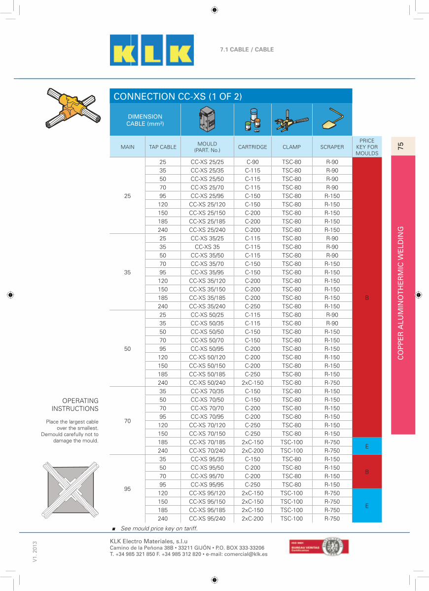
CO
PP
ER
ALU
MIN
OT
HE
RM
IC W
ELD
ING
75
7.1 CABLE / CABLE
V1.
201
310
See mould price key on tariff.
KLK Electro Materiales, s.l.uCamino de la Peñona 38B • 33211 GIJÓN • P.O. BOX 333-33206T. +34 985 321 850 F. +34 985 312 820 • e-mail: [email protected]
CONNECTION CC-XS (1 OF 2)
DIMENSIONCABLE (mm²)
MAIN TAP CABLEMOULD
(PART. No.)CARTRIDGE CLAMP SCRAPER
PRICEKEY FORMOULDS
25
25 CC-XS 25/25 C-90 TSC-80 R-90
B
35 CC-XS 25/35 C-115 TSC-80 R-90
50 CC-XS 25/50 C-115 TSC-80 R-90
70 CC-XS 25/70 C-115 TSC-80 R-90
95 CC-XS 25/95 C-150 TSC-80 R-150
120 CC-XS 25/120 C-150 TSC-80 R-150
150 CC-XS 25/150 C-200 TSC-80 R-150
185 CC-XS 25/185 C-200 TSC-80 R-150
240 CC-XS 25/240 C-200 TSC-80 R-150
35
25 CC-XS 35/25 C-115 TSC-80 R-90
35 CC-XS 35 C-115 TSC-80 R-90
50 CC-XS 35/50 C-115 TSC-80 R-90
70 CC-XS 35/70 C-150 TSC-80 R-150
95 CC-XS 35/95 C-150 TSC-80 R-150
120 CC-XS 35/120 C-200 TSC-80 R-150
150 CC-XS 35/150 C-200 TSC-80 R-150
185 CC-XS 35/185 C-200 TSC-80 R-150
240 CC-XS 35/240 C-250 TSC-80 R-150
50
25 CC-XS 50/25 C-115 TSC-80 R-90
35 CC-XS 50/35 C-115 TSC-80 R-90
50 CC-XS 50/50 C-150 TSC-80 R-150
70 CC-XS 50/70 C-150 TSC-80 R-150
95 CC-XS 50/95 C-200 TSC-80 R-150
120 CC-XS 50/120 C-200 TSC-80 R-150
150 CC-XS 50/150 C-200 TSC-80 R-150
185 CC-XS 50/185 C-250 TSC-80 R-150
240 CC-XS 50/240 2xC-150 TSC-80 R-750
70
35 CC-XS 70/35 C-150 TSC-80 R-150
50 CC-XS 70/50 C-150 TSC-80 R-150
70 CC-XS 70/70 C-200 TSC-80 R-150
95 CC-XS 70/95 C-200 TSC-80 R-150
120 CC-XS 70/120 C-250 TSC-80 R-150
150 CC-XS 70/150 C-250 TSC-80 R-150
185 CC-XS 70/185 2xC-150 TSC-100 R-750E
240 CC-XS 70/240 2xC-200 TSC-100 R-750
95
35 CC-XS 95/35 C-150 TSC-80 R-150
B50 CC-XS 95/50 C-200 TSC-80 R-150
70 CC-XS 95/70 C-200 TSC-80 R-150
95 CC-XS 95/95 C-250 TSC-80 R-150
120 CC-XS 95/120 2xC-150 TSC-100 R-750
E150 CC-XS 95/150 2xC-150 TSC-100 R-750
185 CC-XS 95/185 2xC-150 TSC-100 R-750
240 CC-XS 95/240 2xC-200 TSC-100 R-750
OPERATINGINSTRUCTIONS
Place the largest cableover the smallest.
Demould carefully not todamage the mould.

CO
PP
ER
ALU
MIN
OT
HE
RM
IC W
ELD
ING
76
7.1 CABLE / CABLEV
1. 2
013
11
See mould price key on tariff.
KLK Electro Materiales, s.l.uCamino de la Peñona 38B • 33211 GIJÓN • P.O. BOX 333-33206T. +34 985 321 850 F. +34 985 312 820 • e-mail: [email protected]
CONNECTION CC-XS (MM²) (2 OF 2)
MAIN TAP CABLEMOULD
(PART. No.)CARTRIDGE CLAMP SCRAPER
PRICEKEY FORMOULDS
120
50 CC-XS 120/50 C-200 TSC-80 R-150B
70 CC-XS 120/70 C-250 TSC-80 R-150
95 CC-XS 120/95 2xC-150 TSC-100 R-750
E
120 CC-XS 120/120 2xC-150 TSC-100 R-750
150 CC-XS 120/150 2xC-200 TSC-100 R-750
185 CC-XS 120/185 2xC-250 TSC-100 R-750
240 CC-XS 120/240 2xC-250 TSC-100 R-750
150
50 CC-XS 150/50 C-200 TSC-80 R-150B
70 CC-XS 150/70 C-250 TSC-80 R-150
95 CC-XS 150/95 2xC-150 TSC-100 R-750
E
120 CC-XS 150/120 2xC-200 TSC-100 R-750
150 CC-XS 150/150 2xC-200 TSC-100 R-750
185 CC-XS 150/185 2xC-250 TSC-100 R-750
240 CC-XS 150/240 2xC-250 TSC-100 R-750
185
70 CC-XS 185/70 2xC-150 TSC-100 R-750
95 CC-XS 185/95 2xC-150 TSC-100 R-750
120 CC-XS 185/120 2xC-250 TSC-100 R-750
150 CC-XS 185/150 2xC-250 TSC-100 R-750
185 CC-XS 185/185 2xC-250 TSC-100 R-750
OPERATINGINSTRUCTIONS
Place the largest cableover the smallest.
Demould carefully not todamage the mould.

CO
PP
ER
ALU
MIN
OT
HE
RM
IC W
ELD
ING
77
7.2 CABLE / ROD
V1.
201
312
See mould price key on tariff.
KLK Electro Materiales, s.l.uCamino de la Peñona 38B • 33211 GIJÓN • P.O. BOX 333-33206T. +34 985 321 850 F. +34 985 312 820 • e-mail: [email protected]
CONNECTION CP-AR
DIMENSION
RODCABLE(mm²)
MOULD(PART. No.)
CARTRIDGE CLAMP SCRAPERPRICE
KEY FORMOULDS
143
25 CP-AR 143/25 C-65 TSC-80 R-45
A
35 CP-AR 143/35 C-65 TSC-80 R-4550 CP-AR 143/50 C-90 TSC-80 R-9070 CP-AR 143/70 C-90 TSC-80 R-9095 CP-AR 143/95 C-90 TSC-80 R-90120 CP-AR 143/120 C-90 TSC-80 R-90150 CP-AR 143/150 C-115 TSC-80 R-90185 CP-AR 143/185 C-115 TSC-80 R-90240 CP-AR 143/240 C-150 TSC-80 R-150
146
25 CP-AR 146/25 C-65 TSC-80 R-4535 CP-AR 146/35 C-65 TSC-80 R-4550 CP-AR 146/50 C-90 TSC-80 R-9070 CP-AR 146/70 C-90 TSC-80 R-9095 CP-AR 146/95 C-90 TSC-80 R-90120 CP-AR 146/120 C-90 TSC-80 R-90150 CP-AR 146/150 C-115 TSC-80 R-90185 CP-AR 146/185 C-115 TSC-80 R-90240 CP-AR 146/240 C-150 TSC-80 R-150
58
25 CP-AR 58/25 C-65 TSC-80 R-4535 CP-AR 58/35 C-65 TSC-80 R-4550 CP-AR 58/50 C-90 TSC-80 R-9070 CP-AR 58/70 C-90 TSC-80 R-9095 CP-AR 58/95 C-90 TSC-80 R-90
120 CP-AR 58/120 C-90 TSC-80 R-90150 CP-AR 58/150 C-115 TSC-80 R-90185 CP-AR 58/185 C-115 TSC-80 R-90240 CP-AR 58/240 C-150 TSC-80 R-150
183
25 CP-AR 183/25 C-90 TSC-80 R-9035 CP-AR 183/35 C-90 TSC-80 R-9050 CP-AR 183/50 C-90 TSC-80 R-9070 CP-AR 183/70 C-90 TSC-80 R-9095 CP-AR 183/95 C-90 TSC-80 R-90120 CP-AR 183/120 C-90 TSC-80 R-90150 CP-AR 183/150 C-115 TSC-80 R-90185 CP-AR 183/185 C-115 TSC-80 R-90240 CP-AR 183/240 C-150 TSC-80 R-150
34
25 CP-AR 34/25 C-90 TSC-80 R-9035 CP-AR 34/35 C-90 TSC-80 R-9050 CP-AR 34/50 C-90 TSC-80 R-9070 CP-AR 34/70 C-90 TSC-80 R-9095 CP-AR 34/95 C-90 TSC-80 R-90120 CP-AR 34/120 C-90 TSC-80 R-90150 CP-AR 34/150 C-115 TSC-80 R-90185 CP-AR 34/185 C-115 TSC-80 R-90240 CP-AR 34/240 C-150 TSC-80 R-150
OPERATINGINSTRUCTIONS
Place end of cable at theaxis of the tap hole androd butted against thecable. Use a clamprod
below mould to support it.
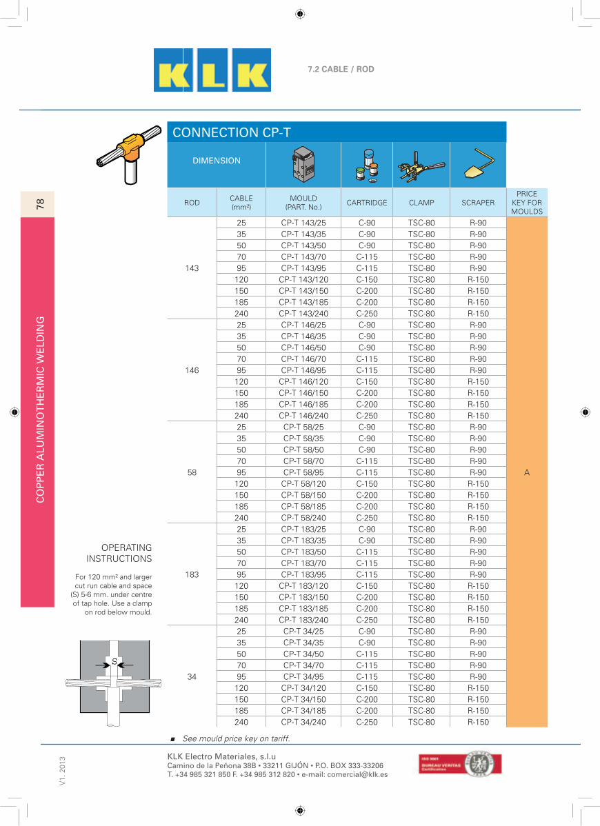
CO
PP
ER
ALU
MIN
OT
HE
RM
IC W
ELD
ING
78
7.2 CABLE / RODV
1. 2
013
13
See mould price key on tariff.
KLK Electro Materiales, s.l.uCamino de la Peñona 38B • 33211 GIJÓN • P.O. BOX 333-33206T. +34 985 321 850 F. +34 985 312 820 • e-mail: [email protected]
CONNECTION CP-T
DIMENSION
RODCABLE(mm²)
MOULD(PART. No.)
CARTRIDGE CLAMP SCRAPERPRICE
KEY FORMOULDS
143
25 CP-T 143/25 C-90 TSC-80 R-90
A
35 CP-T 143/35 C-90 TSC-80 R-9050 CP-T 143/50 C-90 TSC-80 R-9070 CP-T 143/70 C-115 TSC-80 R-9095 CP-T 143/95 C-115 TSC-80 R-90120 CP-T 143/120 C-150 TSC-80 R-150150 CP-T 143/150 C-200 TSC-80 R-150185 CP-T 143/185 C-200 TSC-80 R-150240 CP-T 143/240 C-250 TSC-80 R-150
146
25 CP-T 146/25 C-90 TSC-80 R-9035 CP-T 146/35 C-90 TSC-80 R-9050 CP-T 146/50 C-90 TSC-80 R-9070 CP-T 146/70 C-115 TSC-80 R-9095 CP-T 146/95 C-115 TSC-80 R-90
120 CP-T 146/120 C-150 TSC-80 R-150150 CP-T 146/150 C-200 TSC-80 R-150185 CP-T 146/185 C-200 TSC-80 R-150240 CP-T 146/240 C-250 TSC-80 R-150
58
25 CP-T 58/25 C-90 TSC-80 R-9035 CP-T 58/35 C-90 TSC-80 R-9050 CP-T 58/50 C-90 TSC-80 R-9070 CP-T 58/70 C-115 TSC-80 R-9095 CP-T 58/95 C-115 TSC-80 R-90120 CP-T 58/120 C-150 TSC-80 R-150150 CP-T 58/150 C-200 TSC-80 R-150185 CP-T 58/185 C-200 TSC-80 R-150240 CP-T 58/240 C-250 TSC-80 R-150
183
25 CP-T 183/25 C-90 TSC-80 R-9035 CP-T 183/35 C-90 TSC-80 R-9050 CP-T 183/50 C-115 TSC-80 R-9070 CP-T 183/70 C-115 TSC-80 R-9095 CP-T 183/95 C-115 TSC-80 R-90120 CP-T 183/120 C-150 TSC-80 R-150150 CP-T 183/150 C-200 TSC-80 R-150185 CP-T 183/185 C-200 TSC-80 R-150240 CP-T 183/240 C-250 TSC-80 R-150
34
25 CP-T 34/25 C-90 TSC-80 R-9035 CP-T 34/35 C-90 TSC-80 R-9050 CP-T 34/50 C-115 TSC-80 R-9070 CP-T 34/70 C-115 TSC-80 R-9095 CP-T 34/95 C-115 TSC-80 R-90120 CP-T 34/120 C-150 TSC-80 R-150150 CP-T 34/150 C-200 TSC-80 R-150185 CP-T 34/185 C-200 TSC-80 R-150240 CP-T 34/240 C-250 TSC-80 R-150
OPERATINGINSTRUCTIONS
For 120 mm² and largercut run cable and space
(S) 5-6 mm. under centreof tap hole. Use a clamp
on rod below mould.
S

CO
PP
ER
ALU
MIN
OT
HE
RM
IC W
ELD
ING
79
7.2 CABLE / ROD
V1.
201
314
See mould price key on tariff.
KLK Electro Materiales, s.l.uCamino de la Peñona 38B • 33211 GIJÓN • P.O. BOX 333-33206T. +34 985 321 850 F. +34 985 312 820 • e-mail: [email protected]
CONNECTION CP-TS
DIMENSION
RODCABLE(mm²)
MOULD(PART. No.)
CARTRIDGE CLAMP SCRAPERPRICE
KEY FORMOULDS
143
25 CP-TS 143/25 C-90 TSC-80 R-90
D
35 CP-TS 143/35 C-90 TSC-80 R-9050 CP-TS 143/50 C-115 TSC-80 R-9070 CP-TS 143/70 C-115 TSC-80 R-9095 CP-TS 143/95 C-115 TSC-80 R-90120 CP-TS 143/120 C-150 TSC-80 R-150150 CP-TS 143/150 C-150 TSC-80 R-150185 CP-TS 143/185 C-250 TSC-80 R-150
240 CP-TS 143/240 2xC-200 TSC-80 R-150 H
146
25 CP-TS 146/25 C-90 TSC-80 R-90
D
35 CP-TS 146/35 C-90 TSC-80 R-9050 CP-TS 146/50 C-115 TSC-80 R-9070 CP-TS 146/70 C-115 TSC-80 R-9095 CP-TS 146/95 C-115 TSC-80 R-90120 CP-TS 146/120 C-150 TSC-80 R-150150 CP-TS 146/150 C-150 TSC-80 R-150185 CP-TS 146/185 C-250 TSC-80 R-150
240 CP-TS 146/240 2xC-200 TSC-80 R-150 H
58
25 CP-TS 58/25 C-90 TSC-80 R-90
D
35 CP-TS 58/35 C-90 TSC-80 R-9050 CP-TS 58/50 C-115 TSC-80 R-9070 CP-TS 58/70 C-115 TSC-80 R-9095 CP-TS 58/95 C-115 TSC-80 R-90120 CP-TS 58/120 C-150 TSC-80 R-150150 CP-TS 58/150 C-150 TSC-80 R-150185 CP-TS 58/185 C-250 TSC-80 R-150
240 CP-TS 58/240 2xC-200 TSC-80 R-150 H
183
25 CP-TS 183/25 C-90 TSC-80 R-90
D
35 CP-TS 183/35 C-90 TSC-80 R-9050 CP-TS 183/50 C-115 TSC-80 R-9070 CP-TS 183/70 C-150 TSC-80 R-15095 CP-TS 183/95 C-150 TSC-80 R-150120 CP-TS 183/120 C-200 TSC-80 R-150150 CP-TS 183/150 C-250 TSC-80 R-150185 CP-TS 183/185 2xC-150 TSC-80 R-150
H240 CP-TS 183/240 2xC-250 TSC-80 R-150
34
25 CP-TS 34/25 C-90 TSC-80 R-90
D
35 CP-TS 34/35 C-90 TSC-80 R-9050 CP-TS 34/50 C-115 TSC-80 R-9070 CP-TS 34/70 C-150 TSC-80 R-15095 CP-TS 34/95 C-150 TSC-80 R-150120 CP-TS 34/120 C-200 TSC-80 R-150150 CP-TS 34/150 C-250 TSC-80 R-150185 CP-TS 34/185 2xC-150 TSC-80 R-150
H240 CP-TS 34/240 2xC-250 TSC-80 R-150
OPERATINGINSTRUCTIONS
Insert cable into themould and secure it torod with backing plate
attachment. Use anotherclamp on rod below
mould.

CO
PP
ER
ALU
MIN
OT
HE
RM
IC W
ELD
ING
80
7.2 CABLE / RODV
1. 2
013
15
See mould price key on tariff.
KLK Electro Materiales, s.l.uCamino de la Peñona 38B • 33211 GIJÓN • P.O. BOX 333-33206T. +34 985 321 850 F. +34 985 312 820 • e-mail: [email protected]
CONNECTION CP-V
DIMENSION
RODCABLE(mm²)
MOULD(PART. No.)
CARTRIDGE CLAMP SCRAPERPRICE
KEY FORMOULDS
143
25 CP-V 143/25 C-65 TSC-80 R-45A
35 CP-V 143/35 C-65 TSC-80 R-4550 CP-V 143/50 C-90 TSC-80 R-90
D
70 CP-V 143/70 C-90 TSC-80 R-9095 CP-V 143/95 C-90 TSC-80 R-90120 CP-V 143/120 C-90 TSC-80 R-90150 CP-V 143/150 C-115 TSC-80 R-90185 CP-V 143/185 C-115 TSC-80 R-90240 CP-V 143/240 C-150 TSC-80 R-150
146
25 CP-V 146/25 C-65 TSC-80 R-45A
35 CP-V 146/35 C-65 TSC-80 R-4550 CP-V 146/50 C-90 TSC-80 R-90
D
70 CP-V 146/70 C-90 TSC-80 R-9095 CP-V 146/95 C-90 TSC-80 R-90120 CP-V 146/120 C-90 TSC-80 R-90150 CP-V 146/150 C-115 TSC-80 R-90185 CP-V 146/185 C-115 TSC-80 R-90240 CP-V 146/240 C-150 TSC-80 R-150
58
25 CP-V 58/25 C-65 TSC-80 R-45A
35 CP-V 58/35 C-65 TSC-80 R-4550 CP-V 58/50 C-90 TSC-80 R-90
D
70 CP-V 58/70 C-90 TSC-80 R-9095 CP-V 58/95 C-90 TSC-80 R-90120 CP-V 58/120 C-90 TSC-80 R-90150 CP-V 58/150 C-115 TSC-80 R-90185 CP-V 58/185 C-115 TSC-80 R-90240 CP-V 58/240 C-150 TSC-80 R-150
183
25 CP-V 183/25 C-90 TSC-80 R-9035 CP-V 183/35 C-90 TSC-80 R-9050 CP-V 183/50 C-90 TSC-80 R-9070 CP-V 183/70 C-90 TSC-80 R-9095 CP-V 183/95 C-90 TSC-80 R-90120 CP-V 183/120 C-90 TSC-80 R-90150 CP-V 183/150 C-115 TSC-80 R-90185 CP-V 183/185 C-115 TSC-80 R-90240 CP-V 183/240 C-150 TSC-80 R-150
34
25 CP-V 34/25 C-90 TSC-80 R-9035 CP-V 34/35 C-90 TSC-80 R-9050 CP-V 34/50 C-90 TSC-80 R-9070 CP-V 34/70 C-90 TSC-80 R-9095 CP-V 34/95 C-90 TSC-80 R-90120 CP-V 34/120 C-90 TSC-80 R-90150 CP-V 34/150 C-115 TSC-80 R-90185 CP-V 34/185 C-115 TSC-80 R-90240 CP-V 34/240 C-150 TSC-80 R-150
S
OPERATINGINSTRUCTIONS
Separate rod and cable(S) 5- 6 mm. At the axis ofthe tap hole. Use a clamp
on rod below mould.
CP-V 143/35

CO
PP
ER
ALU
MIN
OT
HE
RM
IC W
ELD
ING
81
7.2 CABLE / ROD
V1.
201
316
See mould price key on tariff.
KLK Electro Materiales, s.l.uCamino de la Peñona 38B • 33211 GIJÓN • P.O. BOX 333-33206T. +34 985 321 850 F. +34 985 312 820 • e-mail: [email protected]
CONNECTION CP-VS
DIMENSION
RODCABLE(mm²)
MOULD(PART. No.)
CARTRIDGE CLAMP SCRAPERPRICE
KEY FORMOULDS
143
25 CP-VS 143/25 C-90 TSC-80 R-90
D
35 CP-VS 143/35 C-90 TSC-80 R-9050 CP-VS 143/50 C-115 TSC-80 R-9070 CP-VS 143/70 C-150 TSC-80 R-15095 CP-VS 143/95 C-150 TSC-80 R-150120 CP-VS 143/120 C-200 TSC-80 R-150150 CP-VS 143/150 C-250 TSC-80 R-150
I185 CP-VS 143/185 2xC-150 TSC-80 R-150240 CP-VS 143/240 2xC-250 TSC-80 R-150
146
25 CP-VS 146/25 C-90 TSC-80 R-90
D
35 CP-VS 146/35 C-90 TSC-80 R-9050 CP-VS 146/50 C-115 TSC-80 R-9070 CP-VS 146/70 C-150 TSC-80 R-15095 CP-VS 146/95 C-150 TSC-80 R-150120 CP-VS 146/120 C-200 TSC-80 R-150150 CP-VS 146/150 C-250 TSC-80 R-150
I185 CP-VS 146/185 2xC-150 TSC-80 R-150240 CP-VS 146/240 2xC-250 TSC-80 R-150
58
25 CP-VS 58/25 C-90 TSC-80 R-90
D
35 CP-VS 58/35 C-90 TSC-80 R-9050 CP-VS 58/50 C-115 TSC-80 R-9070 CP-VS 58/70 C-150 TSC-80 R-9095 CP-VS 58/95 C-200 TSC-80 R-90120 CP-VS 58/120 C-200 TSC-80 R-150150 CP-VS 58/150 C-250 TSC-80 R-150
I185 CP-VS 58/185 2xC-150 TSC-80 R-150240 CP-VS 58/240 2xC-200 TSC-80 R-150
183
25 CP-VS 183/25 C-90 TSC-80 R-90
D
35 CP-VS 183/35 C-90 TSC-80 R-9050 CP-VS 183/50 C-115 TSC-80 R-9070 CP-VS 183/70 C-150 TSC-80 R-15095 CP-VS 183/95 C-200 TSC-80 R-150120 CP-VS 183/120 C-200 TSC-80 R-150150 CP-VS 183/150 C-250 TSC-80 R-150
I185 CP-VS 183/185 2xC-150 TSC-80 R-150240 CP-VS 183/240 2xC-200 TSC-80 R-150
34
25 CP-VS 34/25 C-90 TSC-80 R-90
D
35 CP-VS 34/35 C-90 TSC-80 R-9050 CP-VS 34/50 C-115 TSC-80 R-9070 CP-VS 34/70 C-150 TSC-80 R-15095 CP-VS 34/95 C-200 TSC-80 R-150120 CP-VS 34/120 C-200 TSC-80 R-150150 CP-VS 34/150 C-250 TSC-80 R-150
I185 CP-VS 34/185 2xC-150 TSC-80 R-150240 CP-VS 34/240 2xC-200 TSC-80 R-150
OPERATINGINSTRUCTIONS
Insert cable until theaxis of the tap hole. Use a
clamp on rod below mould.

CO
PP
ER
ALU
MIN
OT
HE
RM
IC W
ELD
ING
82
7.3 ROD / RODV
1. 2
013
17
See mould price key on tariff.
KLK Electro Materiales, s.l.uCamino de la Peñona 38B • 33211 GIJÓN • P.O. BOX 333-33206T. +34 985 321 850 F. +34 985 312 820 • e-mail: [email protected]
CONNECTION PP-V
DIMENSION
RODMOULD
(PART. No.)CARTRIDGE CLAMP SCRAPER
PRICEKEY FORMOULDS
143 PP-V 143 C-200 TSC-80 R-150
D
146 PP-V 146 C-200 TSC-80 R-150
58 PP-V 58 C-200 TSC-80 R-150
183 PP-V 183 2xC-150 TSC-80 R-150
34 PP-V 34 2xC-150 TSC-80 R-150
S
OPERATINGINSTRUCTIONS
Place tip point of therods in the centre of the
tap rod. If they do nothave a point, separate
them (S) 10 mm. Use aclamp on lower rod
below mould.

CO
PP
ER
ALU
MIN
OT
HE
RM
IC W
ELD
ING
83
7.4 CABLE / RE-BAR
V1.
201
318
See mould price key on tariff.
KLK Electro Materiales, s.l.uCamino de la Peñona 38B • 33211 GIJÓN • P.O. BOX 333-33206T. +34 985 321 850 F. +34 985 312 820 • e-mail: [email protected]
CONNECTION CR-XS
DIMENSION
RE-BAR(mm)
CABLE(mm²)
MOULD(PART. No.)
CARTRIDGE CLAMP SCRAPERPRICE
KEY FORMOULDS
10
25 CR-XS 10/25 C-90 TSC-80 R-90
B
35 CR-XS 10/35 C-90 TSC-80 R-90
50 CR-XS 10/50 C-115 TSC-80 R-90
70 CR-XS 10/70 C-150 TSC-80 R-150
95 CR-XS 10/95 C-150 TSC-80 R-150
16
25 CR-XS 16/25 C-115 TSC-100 R-90
E
35 CR-XS 16/35 C-115 TSC-100 R-90
50 CR-XS 16/50 C-150 TSC-100 R-150
70 CR-XS 16/70 C-150 TSC-100 R-150
95 CR-XS 16/95 C-200 TSC-100 R-150
120 CR-XS 16/120 C-200 TSC-100 R-150
150 CR-XS 16/150 C-200 TSC-100 R-150
20
25 CR-XS 20/25 C-115 TSC-100 R-90
35 CR-XS 20/35 C-115 TSC-100 R-90
50 CR-XS 20/50 C-150 TSC-100 R-150
70 CR-XS 20/70 C-150 TSC-100 R-150
95 CR-XS 20/95 C-200 TSC-100 R-150
120 CR-XS 20/120 C-200 TSC-100 R-150
150 CR-XS 20/150 C-250 TSC-100 R-150
185 CR-XS 20/185 C-250 TSC-100 R-150
240 CR-XS 20/240 2xC-150 TSC-100 R-750
OPERATINGINSTRUCTIONS
Seal the re-bar withpaste on both sides ofthe weld cavity. Place
cable over the top of rebar.

CO
PP
ER
ALU
MIN
OT
HE
RM
IC W
ELD
ING
84
7.4 CABLE / RE-BARV
1. 2
013
19
See mould price key on tariff.
KLK Electro Materiales, s.l.uCamino de la Peñona 38B • 33211 GIJÓN • P.O. BOX 333-33206T. +34 985 321 850 F. +34 985 312 820 • e-mail: [email protected]
CONNECTION CR-TH
DIMENSION
RE-BAR(mm)
CABLE(mm²)
MOULD(PART. No.)
CARTRIDGE CLAMP SCRAPERPRICE
KEY FORMOULDS
10
25 CR-TH 10/25 C-90 TSC-80 R-90
A
35 CR-TH 10/35 C-90 TSC-80 R-90
50 CR-TH 10/50 C-115 TSC-80 R-90
70 CR-TH 10/70 C-115 TSC-80 R-90
95 CR-TH 10/95 C-150 TSC-80 R-150
16
25 CR-TH 16/25 C-150 TSC-80 R-150
35 CR-TH 16/35 C-150 TSC-80 R-150
50 CR-TH 16/50 C-150 TSC-80 R-150
70 CR-TH 16/70 C-150 TSC-80 R-150
95 CR-TH 16/95 C-200 TSC-80 R-150
120 CR-TH 16/120 C-200 TSC-80 R-150
150 CR-TH 16/150 C-250 TSC-80 R-150
20
25 CR-TH 20/25 C-150 TSC-80 R-150
35 CR-TH 20/35 C-150 TSC-80 R-150
50 CR-TH 20/50 C-200 TSC-80 R-150
70 CR-TH 20/70 C-200 TSC-80 R-150
95 CR-TH 20/95 C-200 TSC-80 R-150
120 CR-TH 20/120 C-250 TSC-80 R-150
150 CR-TH 20/150 C-250 TSC-80 R-150
185 CR-TH 20/185 2xC-150 TSC-80 R-150
240 CR-TH 20/240 2xC-200 TSC-100 R-750 E
OPERATINGINSTRUCTIONS
Seal the re-bar withpast on both sides of the
weld cavity, on the out-side.
Butt tap cable against there-bar.

CO
PP
ER
ALU
MIN
OT
HE
RM
IC W
ELD
ING
85
7.4 CABLE / RE-BAR
V1.
201
320
See mould price key on tariff.
KLK Electro Materiales, s.l.uCamino de la Peñona 38B • 33211 GIJÓN • P.O. BOX 333-33206T. +34 985 321 850 F. +34 985 312 820 • e-mail: [email protected]
CONNECTION CR-TL
DIMENSION
RE-BAR(mm)
CABLE(mm²)
MOULD(PART. No.)
CARTRIDGE CLAMP SCRAPERPRICE
KEY FORMOULDS
10
25 CR-TL 10/25 C-90 TSC-80 R-90
D
35 CR-TL 10/35 C-90 TSC-80 R-90
50 CR-TL 10/50 C-115 TSC-80 R-90
70 CR-TL 10/70 C-115 TSC-80 R-90
95 CR-TL 10/95 C-150 TSC-80 R-150
120 CR-TL 10/120 C-150 TSC-80 R-150
150 CR-TL 10/150 C-200 TSC-80 R-150
16
25 CR-TL 16/25 C-150 TSC-80 R-150
35 CR-TL 16/35 C-150 TSC-80 R-150
50 CR-TL 16/50 C-150 TSC-80 R-150
70 CR-TL 16/70 C-150 TSC-80 R-150
95 CR-TL 16/95 C-200 TSC-80 R-150
120 CR-TL 16/120 C-200 TSC-80 R-150
150 CR-TL 16/150 C-250 TSC-80 R-150
20
25 CR-TL 20/25 C-150 TSC-80 R-150
35 CR-TL 20/35 C-150 TSC-80 R-150
50 CR-TL 20/50 C-200 TSC-80 R-150
70 CR-TL 20/70 C-200 TSC-80 R-150
95 CR-TL 20/95 C-200 TSC-80 R-150
120 CR-TL 20/120 C-250 TSC-80 R-150
150 CR-TL 20/150 C-250 TSC-80 R-150
185 CR-TL 20/185 2xC-150 TSC-80 R-150
240 CR-TL 20/240 2xC-200 TSC-80 R-150
OPERATINGINSTRUCTIONS
Seal the re-barwith paste below theweld cavity. Butt thetap cable against the
re-bar. Use a clamp onre-bar below mould.

CO
PP
ER
ALU
MIN
OT
HE
RM
IC W
ELD
ING
86
7.4 CABLE / RE-BARV
1. 2
013
21
See mould price key on tariff.
KLK Electro Materiales, s.l.uCamino de la Peñona 38B • 33211 GIJÓN • P.O. BOX 333-33206T. +34 985 321 850 F. +34 985 312 820 • e-mail: [email protected]
CONNECTION CR-PV
DIMENSION
RE-BAR(mm)
CABLE(mm²)
MOULD(PART. No.)
CARTRIDGE CLAMP SCRAPERPRICE
KEY FORMOULDS
10
25 CR-PV 10/25 C-90 TSC-80 R-90
D
35 CR-PV 10/35 C-90 TSC-80 R-90
50 CR-PV 10/50 C-115 TSC-80 R-90
70 CR-PV 10/70 C-150 TSC-80 R-150
95 CR-PV 10/95 C-150 TSC-80 R-150
16
25 CR-PV 16/25 C-115 TSC-80 R-90
35 CR-PV 16/35 C-115 TSC-80 R-90
50 CR-PV 16/50 C-150 TSC-80 R-150
70 CR-PV 16/70 C-150 TSC-80 R-150
95 CR-PV 16/95 C-200 TSC-80 R-150
120 CR-PV 16/120 C-200 TSC-80 R-150
150 CR-PV 16/150 C-200 TSC-80 R-150
20
25 CR-PV 20/25 C-115 TSC-80 R-90
35 CR-PV 20/35 C-115 TSC-80 R-90
50 CR-PV 20/50 C-150 TSC-80 R-150
70 CR-PV 20/70 C-150 TSC-80 R-150
95 CR-PV 20/95 C-200 TSC-80 R-150
120 CR-PV 20/120 C-200 TSC-80 R-150
150 CR-PV 20/150 C-250 TSC-80 R-150
185 CR-PV 20/185 C-250 TSC-80 R-150
240 CR-PV 20/240 2xC-150 TSC-80 R-150OPERATING
INSTRUCTIONS
Seal the re-bar withpaste on both sides ofthe weld cavity, on the
outside. Insert the cablein the mould and secure
it to the re-bar.Place the backing partand secure it to re-bar.Use a clamp on cable
below mould.
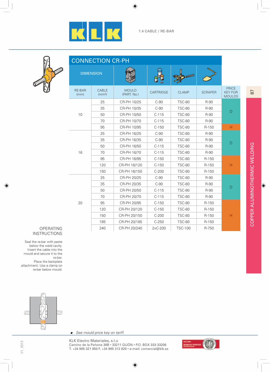
CO
PP
ER
ALU
MIN
OT
HE
RM
IC W
ELD
ING
87
7.4 CABLE / RE-BAR
V1.
201
322
See mould price key on tariff.
KLK Electro Materiales, s.l.uCamino de la Peñona 38B • 33211 GIJÓN • P.O. BOX 333-33206T. +34 985 321 850 F. +34 985 312 820 • e-mail: [email protected]
CONNECTION CR-PH
DIMENSION
RE-BAR(mm)
CABLE(mm²)
MOULD(PART. No.)
CARTRIDGE CLAMP SCRAPERPRICE
KEY FORMOULDS
10
25 CR-PH 10/25 C-90 TSC-80 R-90
D35 CR-PH 10/35 C-90 TSC-80 R-90
50 CR-PH 10/50 C-115 TSC-80 R-90
70 CR-PH 10/70 C-115 TSC-80 R-90
95 CR-PH 10/95 C-150 TSC-80 R-150 H
16
25 CR-PH 16/25 C-90 TSC-80 R-90
D35 CR-PH 16/35 C-90 TSC-80 R-90
50 CR-PH 16/50 C-115 TSC-80 R-90
70 CR-PH 16/70 C-115 TSC-80 R-90
95 CR-PH 16/95 C-150 TSC-80 R-150
H120 CR-PH 16/120 C-150 TSC-80 R-150
150 CR-PH 16/150 C-200 TSC-80 R-150
20
25 CR-PH 20/25 C-90 TSC-80 R-90
D35 CR-PH 20/35 C-90 TSC-80 R-90
50 CR-PH 20/50 C-115 TSC-80 R-90
70 CR-PH 20/70 C-115 TSC-80 R-90
95 CR-PH 20/95 C-150 TSC-80 R-150
H
120 CR-PH 20/120 C-150 TSC-80 R-150
150 CR-PH 20/150 C-200 TSC-80 R-150
185 CR-PH 20/185 C-250 TSC-80 R-150
240 CR-PH 20/240 2xC-200 TSC-100 R-750OPERATINGINSTRUCTIONS
Seal the re-bar with pastebelow the weld cavity.
Insert the cable into themould and secure it to the
re-bar.Place the backplate
attachment. Use a clamp onre-bar below mould.

CO
PP
ER
ALU
MIN
OT
HE
RM
IC W
ELD
ING
88
7.4 CABLE / RE-BARV
1. 2
013
23
See mould price key on tariff.
KLK Electro Materiales, s.l.uCamino de la Peñona 38B • 33211 GIJÓN • P.O. BOX 333-33206T. +34 985 321 850 F. +34 985 312 820 • e-mail: [email protected]
CONNECTION CR-TP
DIMENSION
RE-BAR(mm)
CABLE(mm²)
MOULD(PART. No.)
CARTRIDGE CLAMP SCRAPERPRICE
KEY FORMOULDS
10
25 CR-TP 10/25 C-90 TSC-80 R-90
A
35 CR-TP 10/35 C-90 TSC-80 R-90
50 CR-TP 10/50 C-115 TSC-80 R-90
70 CR-TP 10/70 C-115 TSC-80 R-90
95 CR-TP 10/95 C-150 TSC-80 R-150
16
25 CR-TP 16/25 C-90 TSC-80 R-90
35 CR-TP 16/35 C-90 TSC-80 R-90
50 CR-TP 16/50 C-115 TSC-80 R-90
70 CR-TP 16/70 C-115 TSC-80 R-90
95 CR-TP 16/95 C-150 TSC-80 R-150
120 CR-TP 16/120 C-150 TSC-80 R-150
150 CR-TP 16/150 C-200 TSC-80 R-150
20
25 CR-TP 20/25 C-90 TSC-80 R-90
35 CR-TP 20/35 C-90 TSC-80 R-90
50 CR-TP 20/50 C-115 TSC-80 R-90
70 CR-TP 20/70 C-115 TSC-80 R-90
95 CR-TP 20/95 C-150 TSC-80 R-150
120 CR-TP 20/120 C-150 TSC-80 R-150
150 CR-TP 20/150 C-200 TSC-80 R-150
185 CR-TP 20/185 C-250 TSC-80 R-150
240 CR-TP 20/240 C-250 TSC-80 R-150
OPERATINGINSTRUCTIONS
Seal the re-bar withpaste on both sides ofthe weld cavity, on the
outside. Insert thecable up to the centre
of the tap hole.
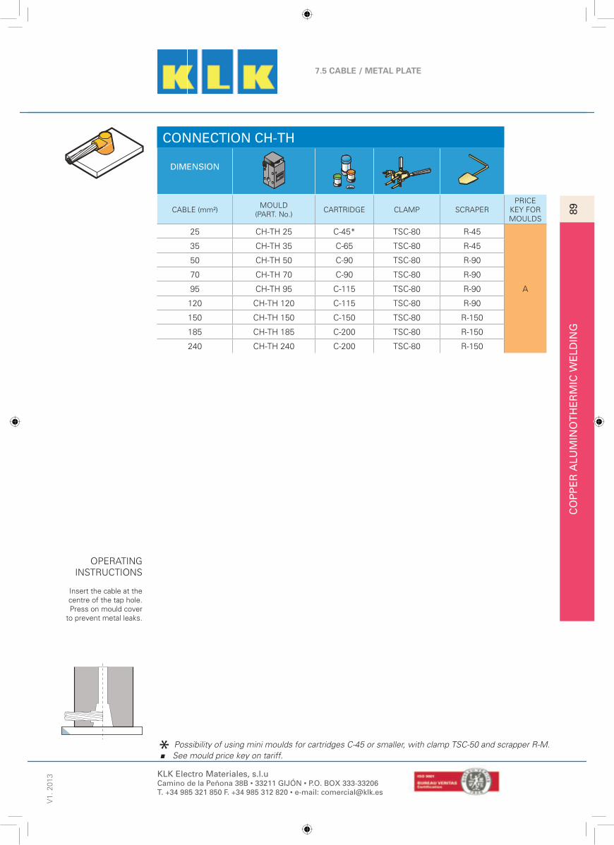
CO
PP
ER
ALU
MIN
OT
HE
RM
IC W
ELD
ING
89
7.5 CABLE / METAL PLATE
V1.
201
324
See mould price key on tariff.
KLK Electro Materiales, s.l.uCamino de la Peñona 38B • 33211 GIJÓN • P.O. BOX 333-33206T. +34 985 321 850 F. +34 985 312 820 • e-mail: [email protected]
CONNECTION CH-TH
DIMENSION
CABLE (mm²)MOULD
(PART. No.)CARTRIDGE CLAMP SCRAPER
PRICEKEY FORMOULDS
25 CH-TH 25 C-45* TSC-80 R-45
A
35 CH-TH 35 C-65 TSC-80 R-45
50 CH-TH 50 C-90 TSC-80 R-90
70 CH-TH 70 C-90 TSC-80 R-90
95 CH-TH 95 C-115 TSC-80 R-90
120 CH-TH 120 C-115 TSC-80 R-90
150 CH-TH 150 C-150 TSC-80 R-150
185 CH-TH 185 C-200 TSC-80 R-150
240 CH-TH 240 C-200 TSC-80 R-150
OPERATINGINSTRUCTIONS
Insert the cable at thecentre of the tap hole.Press on mould cover
to prevent metal leaks.
Possibility of using mini moulds for cartridges C-45 or smaller, with clamp TSC-50 and scrapper R-M.

CO
PP
ER
ALU
MIN
OT
HE
RM
IC W
ELD
ING
90
7.5 CABLE / METAL PLATEV
1. 2
013
25
See mould price key on tariff.
KLK Electro Materiales, s.l.uCamino de la Peñona 38B • 33211 GIJÓN • P.O. BOX 333-33206T. +34 985 321 850 F. +34 985 312 820 • e-mail: [email protected]
CONNECTION CH-TF
DIMENSION
CABLE (mm²)MOULD
(PART. No.)CARTRIDGE CLAMP SCRAPER
PRICEKEY FORMOULDS
25 CH-TF 25 C-45* TSC-80 R-45
A
35 CH-TF 35 C-45* TSC-80 R-45
50 CH-TF 50 C-90 TSC-80 R-90
70 CH-TF 70 C-90 TSC-80 R-90
95 CH-TF 95 C-115 TSC-80 R-90
120 CH-TF 120 C-115 TSC-80 R-90
150 CH-TF 150 C-150 TSC-80 R-150
185 CH-TF 185 C-200 TSC-80 R-150
240 CH-TF 240 C-200 TSC-80 R-150
OPERATINGINSTRUCTIONS
Insert the cable untilreaching the metalplate. Secure withclamp, if possible.
Possibility of using mini moulds for cartridges C-45 or smaller, with clamp TSC-50 and scrapper R-M.

CO
PP
ER
ALU
MIN
OT
HE
RM
IC W
ELD
ING
91
7.5 CABLE / METAL PLATE
V1.
201
326
See mould price key on tariff.
KLK Electro Materiales, s.l.uCamino de la Peñona 38B • 33211 GIJÓN • P.O. BOX 333-33206T. +34 985 321 850 F. +34 985 312 820 • e-mail: [email protected]
CONNECTION CH-VI
DIMENSION
CABLE (mm²)MOULD
(PART. No.)CARTRIDGE CLAMP SCRAPER
PRICEKEY FORMOULDS
25 CH-VI 25 C-45* TSC-80 R-45
A
35 CH-VI 35 C-65 TSC-80 R-45
50 CH-VI 50 C-90 TSC-80 R-90
70 CH-VI 70 C-90 TSC-80 R-90
95 CH-VI 95 C-115 TSC-80 R-90
120 CH-VI 120 C-115 TSC-80 R-90
150 CH-VI 150 C-150 TSC-80 R-150
185 CH-VI 185 C-150 TSC-80 R-150
240 CH-VI 240 C-200 TSC-80 R-150
OPERATINGINSTRUCTIONS
Insert the cable until the centre of the tap hole. Seal the space
between the cable and the plate with mastic
below the weld cavity.Secure mould to the plate with a clamp, if
possible.
Possibility of using mini moulds for cartridges C-45 or smaller, with clamp TSC-50 and scrapper R-M. See

CO
PP
ER
ALU
MIN
OT
HE
RM
IC W
ELD
ING
92
7.5 CABLE / METAL PLATEV
1. 2
013
27
See mould price key on tariff.
KLK Electro Materiales, s.l.uCamino de la Peñona 38B • 33211 GIJÓN • P.O. BOX 333-33206T. +34 985 321 850 F. +34 985 312 820 • e-mail: [email protected]
CONNECTION CH-TVD/CH-TVI
DIMENSION
CABLE (mm²)MOULD
(PART. No.)CARTRIDGE CLAMP SCRAPER
PRICEKEY FORMOULDS
25 CH-TVD/ CH-TVI 25 C-45* TSC-80 R-45
A
35 CH-TVD/ CH-TVI 35 C-65 TSC-80 R-45
50 CH-TVD/ CH-TVI 50 C-90 TSC-80 R-90
70 CH-TVD/ CH-TVI 70 C-90 TSC-80 R-90
95 CH-TVD/ CH-TVI 95 C-115 TSC-80 R-90
120 CH-TVD/ CH-TVI 120 C-115 TSC-80 R-90
150 CH-TVD/ CH-TVI 150 C-150 TSC-80 R-150
185 CH-TVD/ CH-TVI 185 C-200 TSC-80 R-150
240 CH-TVD/ CH-TVI 240 C-200 TSC-80 R-150
OPERATINGINSTRUCTIONS
Insert the cable up to thecentre of the tap hole.
Seal the space betweenthe cable and the plate
outside the weld cavity.Secure the mould to the
plate with a clamp, ifpossible.
Possibility of using mini moulds for cartridges C-45 or smaller, with clamp TSC-50 and scrapper R-M.

CO
PP
ER
ALU
MIN
OT
HE
RM
IC W
ELD
ING
93
7.5 CABLE / METAL PLATE
V1.
201
328
See mould price key on tariff.
KLK Electro Materiales, s.l.uCamino de la Peñona 38B • 33211 GIJÓN • P.O. BOX 333-33206T. +34 985 321 850 F. +34 985 312 820 • e-mail: [email protected]
CONNECTION CH-PHH
DIMENSION
CABLE (mm²)MOULD
(PART. No.)CARTRIDGE CLAMP SCRAPER
PRICEKEY FORMOULDS
25 CH-PHH 25 C-65 TSC-80 R-45
A
35 CH-PHH 35 C-90 TSC-80 R-90
50 CH-PHH 50 C-90 TSC-80 R-90
70 CH-PHH 70 C-115 TSC-80 R-90
95 CH-PHH 95 C-115 TSC-80 R-90
120 CH-PHH 120 C-150 TSC-80 R-150
150 CH-PHH 150 C-200 TSC-80 R-150
185 CH-PHH 185 C-250 TSC-80 R-150
240 CH-PHH 240 2xC-150 TSC-80 R-150
OPERATINGINSTRUCTIONS
Cut and separate thecable 3 to 4 mm.
Under centre of taphole. Press on the
cover of the mould toprevent metal leaks.
S

CO
PP
ER
ALU
MIN
OT
HE
RM
IC W
ELD
ING
94
7.5 CABLE / METAL PLATEV
1. 2
013
29
See mould price key on tariff.
KLK Electro Materiales, s.l.uCamino de la Peñona 38B • 33211 GIJÓN • P.O. BOX 333-33206T. +34 985 321 850 F. +34 985 312 820 • e-mail: [email protected]
CONNECTION CH-PVH
DIMENSION
CABLE (mm²)MOULD
(PART. No.)CARTRIDGE CLAMP SCRAPER
PRICEKEY FORMOULDS
25 CH-PVH 25 C-65 TSC-80 R-45
A
35 CH-PVH 35 C-90 TSC-80 R-90
50 CH-PVH 50 C-115 TSC-80 R-90
70 CH-PVH 70 C-115 TSC-80 R-90
95 CH-PVH 95 C-150 TSC-80 R-150
120 CH-PVH 120 C-150 TSC-80 R-150
150 CH-PVH 150 C-200 TSC-80 R-150
185 CH-PVH 185 C-250 TSC-80 R-150
240 CH-PVH 240 2xC-150 TSC-80 R-150
OPERATINGINSTRUCTIONS
Seal the spacebetween the cable andthe plate on both sides
of the weld cavity.Secure the mould to the
plate with a clamp, if possible.
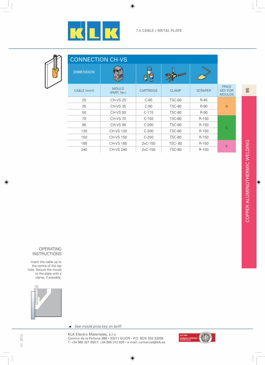
CO
PP
ER
ALU
MIN
OT
HE
RM
IC W
ELD
ING
95
7.5 CABLE / METAL PLATE
V1.
201
330
See mould price key on tariff.
KLK Electro Materiales, s.l.uCamino de la Peñona 38B • 33211 GIJÓN • P.O. BOX 333-33206T. +34 985 321 850 F. +34 985 312 820 • e-mail: [email protected]
CONNECTION CH-VS
DIMENSION
CABLE (mm²)MOULD
(PART. No.)CARTRIDGE CLAMP SCRAPER
PRICEKEY FORMOULDS
25 CH-VS 25 C-65 TSC-80 R-45
A35 CH-VS 35 C-90 TSC-80 R-90
50 CH-VS 50 C-115 TSC-80 R-90
70 CH-VS 70 C-150 TSC-80 R-150
C95 CH-VS 95 C-200 TSC-80 R-150
120 CH-VS 120 C-200 TSC-80 R-150
150 CH-VS 150 C-250 TSC-80 R-150
185 CH-VS 185 2xC-150 TSC- 80 R-150F
240 CH-VS 240 2xC-150 TSC-80 R-150
OPERATINGINSTRUCTIONS
Insert the cable up tothe centre of the tap
hole. Secure the mouldto the plate with aclamp, if possible.

CO
PP
ER
ALU
MIN
OT
HE
RM
IC W
ELD
ING
96
7.5 CABLE / METAL PLATEV
1. 2
013
31
See mould price key on tariff.
KLK Electro Materiales, s.l.uCamino de la Peñona 38B • 33211 GIJÓN • P.O. BOX 333-33206T. +34 985 321 850 F. +34 985 312 820 • e-mail: [email protected]
CONNECTION CH-PVV
DIMENSION
CABLE (mm²)MOULD
(PART. No.)CARTRIDGE CLAMP SCRAPER
PRICEKEY FORMOULDS
25 CH-PVV 25 C-90 TSC-80 R-90A
35 CH-PVV 35 C-115 TSC-80 R-90
50 CH-PVV 50 C-150 TSC-80 R-150
C70 CH-PVV 70 C-200 TSC-80 R-150
95 CH-PVV 95 C-250 TSC-80 R-150
120 CH-PVV 120 C-250 TSC-80 R-150
150 CH-PVV 150 2xC-150 TSC-100 R-750
F185 CH-PVV 185 2xC-150 TSC-100 R-750
240 CH-PVV 240 2xC-200 TSC-100 R-750
OPERATINGINSTRUCTIONS
Cut and separate thecable 5 to 6 mm in thecentre of the tap hole.Seal the gap between
the cable and theplate with mastic
below the weld cavity.Secure the mould with
a clamp, if possible.

CO
PP
ER
ALU
MIN
OT
HE
RM
IC W
ELD
ING
97
7.6 CABLE / PIPE
V1.
201
332
See mould price key on tariff.
KLK Electro Materiales, s.l.uCamino de la Peñona 38B • 33211 GIJÓN • P.O. BOX 333-33206T. +34 985 321 850 F. +34 985 312 820 • e-mail: [email protected]
CONNECTION CT-TH
DIMENSION
CABLE (mm²)MOULD
(PART. No.)CARTRIDGE CLAMP SCRAPER
PRICEKEY FORMOULDS
10 CT-TH 10 C-15 MS R-45
A
16 CT-TH 16 C-15 MS R-45
25 CT-TH 25 C-25 MS R-45
35 CT-TH 35 C-32 MS R-45
50 CT-TH 50 C-45 MS R-45
70 CT-TH 70 C-65 MS R-45
OPERATINGINSTRUCTIONS
Insert the cable untilthe centre of the tap
hole. Seal the gapbetween the cableand the plate withmastic outside theweld cavity. Press
on the mould toprevent metal leaks.

CO
PP
ER
ALU
MIN
OT
HE
RM
IC W
ELD
ING
98
7.7 CABLE / BUS-BARV
1. 2
013
33
See mould price key on tariff.
KLK Electro Materiales, s.l.uCamino de la Peñona 38B • 33211 GIJÓN • P.O. BOX 333-33206T. +34 985 321 850 F. +34 985 312 820 • e-mail: [email protected]
CONNECTION CPL-VI (1 OF 2)
DIMENSION
CABLE(mm²)
BUS-BAR PART. No. CARTRIDGE CLAMP SCRAPERPRICE
KEY FORMOULDS
25
20x2 CPL-VI 25/20x2 C-65 TSC-80 R-45
A
20x3 CPL-VI 25/20x3 C-90 TSC-80 R-90
20x5 CPL-VI 25/20x5 C-90 TSC-80 R-90
25x3 CPL-VI 25/25x3 C-90 TSC-80 R-90
25x5 CPL-VI 25/25x5 C-115 TSC-80 R-90
30x3 CPL-VI 25/30x3 C-115 TSC-80 R-90
35
20x3 CPL-VI 35/20x3 C-115 TSC-80 R-90
20x5 CPL-VI 35/20x5 C-115 TSC-80 R-90
25x3 CPL-VI 35/25x3 C-115 TSC-80 R-90
25x5 CPL-VI 35/25x5 C-115 TSC-80 R-90
30x3 CPL-VI 35/30x3 C-115 TSC-80 R-90
40x3 CPL-VI 35/40x3 C-115 TSC-80 R-90
40x5 CPL-VI 35/40x5 C-115 TSC-80 R-90
50
20x3 CPL-VI 50/20x3 C-115 TSC-80 R-90
20x5 CPL-VI 50/20x5 C-115 TSC-80 R-90
25x3 CPL-VI 50/25x3 C-115 TSC-80 R-90
25x5 CPL-VI 50/25x5 C-115 TSC-80 R-90
30x3 CPL-VI 50/30x3 C-115 TSC-80 R-90
30x5 CPL-VI 50/30x5 C-115 TSC-80 R-90
40x3 CPL-VI 50/40x3 C-115 TSC-80 R-90
40x5 CPL-VI 50/40x5 C-115 TSC-80 R-90
50x5 CPL-VI 50/50x5 C-150 TSC-80 R-150
70
20x3 CPL-VI 70/20x3 C-115 TSC-80 R-90
20x5 CPL-VI 70/20x5 C-150 TSC-80 R-150
25x3 CPL-VI 70/25x3 C-150 TSC-80 R-150
25x5 CPL-VI 70/25x5 C-150 TSC-80 R-150
30x3 CPL-VI 70/30x3 C-150 TSC-80 R-150
30x5 CPL-VI 70/30x5 C-150 TSC-80 R-150
40x3 CPL-VI 70/40x3 C-150 TSC-80 R-150
40x5 CPL-VI 70/40x5 C-150 TSC-80 R-150
50x5 CPL-VI 70/50x5 C-200 TSC-80 R-150
OPERATINGINSTRUCTIONS
Insert end of tap cableeven with upper edge
of run bus-bar, seal thegap between the cable
and the mould withmastic below the weld
cavity.

SO
LDA
DU
RA
ALU
MIN
OT
ÉR
MIC
A D
EL
CO
BR
E99
7.7 CABLE / BUS-BAR
V1.
201
334
See mould price key on tariff.
KLK Electro Materiales, s.l.uCamino de la Peñona 38B • 33211 GIJÓN • P.O. BOX 333-33206T. +34 985 321 850 F. +34 985 312 820 • e-mail: [email protected]
CONNECTION CPL-VI (2 OF 2)CABLE(mm²)
BUS-BAR PART. No. CARTRIDGE CLAMP SCRAPERPRICE
KEY FORMOULDS
95
20x3 CPL-VI 95/20x3 C-150 TSC-80 R-150
A
20x5 CPL-VI 95/20x5 C-150 TSC-80 R-150
25x3 CPL-VI 95/25x3 C-150 TSC-80 R-150
25x5 CPL-VI 95/25x5 C-150 TSC-80 R-150
30x3 CPL-VI 95/30x3 C-200 TSC-80 R-150
30x5 CPL-VI 95/30x5 C-200 TSC-80 R-150
40x3 CPL-VI 95/40x3 C-200 TSC-80 R-150
40x5 CPL-VI 95/40x5 C-200 TSC-80 R-150
50x5 CPL-VI 95/50x5 C-250 TSC-80 R-150
60x5 CPL-VI 95/60x5 2xC-150 TSC-100 R-750 D
120
20x5 CPL-VI 120/20x5 C-200 TSC-80 R-150
A
25x3 CPL-VI 120/25x3 C-200 TSC-80 R-150
25x5 CPL-VI 120/25x5 C-200 TSC-80 R-150
30x3 CPL-VI 120/30x3 C-200 TSC-80 R-150
30x5 CPL-VI 120/30x5 C-200 TSC-80 R-150
40x3 CPL-VI 120/40x3 C-250 TSC-80 R-150
40x5 CPL-VI 120/40x5 C-250 TSC-80 R-150
50x5 CPL-VI 120/50x5 2xC-150 TSC-100 R-750D
60x5 CPL-VI 120/60x5 2xC-150 TSC-100 R-750
150
25x5 CPL-VI 150/25x5 C-200 TSC-80 R-150
A
30x3 CPL-VI 150/30x3 C-200 TSC-80 R-150
30x5 CPL-VI 150/30x5 C-200 TSC-80 R-150
40x3 CPL-VI 150/40x3 C-250 TSC-80 R-150
40x5 CPL-VI 150/40x5 C-250 TSC-80 R-150
50x5 CPL-VI 150/50x5 2xC-150 TSC-100 R-750D
60x5 CPL-VI 150/60x5 2xC-150 TSC-100 R-750
185
25x5 CPL-VI 185/25x5 C-250 TSC-80 R-150
A30x3 CPL-VI 185/30x3 C-250 TSC-80 R-150
30x5 CPL-VI 185/30x5 C-250 TSC-80 R-150
40x3 CPL-VI 185/40x3 2xC-150 TSC-100 R-750
D
40x5 CPL-VI 185/40x5 2xC-150 TSC-100 R-750
50x5 CPL-VI 185/50x5 2xC-150 TSC-100 R-750
60x5 CPL-VI 185/60x5 2xC-200 TSC-100 R-750
240
25x6 CPL-VI 240/25x6 C-250 TSC-100 R-750
30x7 CPL-VI 240/30x7 C-250 TSC-100 R-750
30x9 CPL-VI 240/30x9 C-250 TSC-100 R-750
40x7 CPL-VI 240/40x7 2xC-150 TSC-100 R-750
40x9 CPL-VI 240/40x9 2xC-150 TSC-100 R-750
50x6 CPL-VI 240/50x6 2xC-150 TSC-100 R-750
60x6 CPL-VI 240/60x6 2xC-200 TSC-100 R-750
OPERATINGINSTRUCTIONS
Insert end of tap cableeven with upper edge
of run bus-bar, seal thegap between the cable
and the mould withmastic below the weld
cavity.

CO
PP
ER
ALU
MIN
OT
HE
RM
IC W
ELD
ING
100
7.7 CABLE / BUS-BARV
1. 2
013
35
See mould price key on tariff.
KLK Electro Materiales, s.l.uCamino de la Peñona 38B • 33211 GIJÓN • P.O. BOX 333-33206T. +34 985 321 850 F. +34 985 312 820 • e-mail: [email protected]
CONNECTION CPL-VS (1 OF 2)
DIMENSION
CABLE(mm²)
BUS-BAR PART. No. CARTRIDGE CLAMP SCRAPERPRICE
KEY FORMOULDS
25
20x2 CPL-VS 25/20x2 C-45 TSC-80 R-45
D
20x3 CPL-VS 25/20x3 C-65 TSC-80 R-45
20x5 CPL-VS 25/20x5 C-65 TSC-80 R-45
25x3 CPL-VS 25/25x3 C-90 TSC-80 R-90
25x5 CPL-VS 25/25x5 C-90 TSC-80 R-90
35
20x2 CPL-VS 35/20x2 C-65 TSC-80 R-45
20x3 CPL-VS 35/20x3 C-90 TSC-80 R-90
20x5 CPL-VS 35/20x5 C-90 TSC-80 R-90
25x3 CPL-VS 35/25x3 C-90 TSC-80 R-90
25x5 CPL-VS 35/25x5 C-115 TSC-80 R-90
30x3 CPL-VS 35/30x3 C-115 TSC-80 R-90
50
20x3 CPL-VS 50/20x3 C-115 TSC-80 R-90
20x5 CPL-VS 50/20x5 C-115 TSC-80 R-90
25x3 CPL-VS 50/25x3 C-115 TSC-80 R-90
25x5 CPL-VS 50/25x5 C-115 TSC-80 R-90
30x3 CPL-VS 50/30x3 C-115 TSC-80 R-90
30x5 CPL-VS 50/30x5 C-115 TSC-80 R-90
40x3 CPL-VS 50/40x3 C-115 TSC-80 R-90
40x5 CPL-VS 50/40x5 C-115 TSC-80 R-90
70
20x3 CPL-VS 70/20x3 C-115 TSC-80 R-90
20x5 CPL-VS 70/20x5 C-115 TSC-80 R-90
25x3 CPL-VS 70/25x3 C-115 TSC-80 R-90
25x5 CPL-VS 70/25x5 C-115 TSC-80 R-90
30x3 CPL-VS 70/30x3 C-115 TSC-80 R-90
30x5 CPL-VS 70/30x5 C-115 TSC-80 R-90
40x3 CPL-VS 70/40x3 C-115 TSC-80 R-90
40x5 CPL-VS 70/40x5 C-115 TSC-80 R-90
50x5 CPL-VS 70/50x5 C-150 TSC-80 R-150
OPERATINGINSTRUCTIONS
Run bus-bar is insertedto seat in mould. Butt
tap cable against upperedge of run bus-bar.

CO
PP
ER
ALU
MIN
OT
HE
RM
IC W
ELD
ING
101
7.7 CABLE / BUS-BAR
V1.
201
336
See mould price key on tariff.
KLK Electro Materiales, s.l.uCamino de la Peñona 38B • 33211 GIJÓN • P.O. BOX 333-33206T. +34 985 321 850 F. +34 985 312 820 • e-mail: [email protected]
CONNECTION CPL-VS (2 OF 2)CABLE(mm²)
BUS-BAR PART. No. CARTRIDGE CLAMP SCRAPERPRICE
KEY FORMOULDS
95
20x3 CPL-VS 95/20x3 C-115 TSC-80 R-90
D
20x5 CPL-VS 95/20x5 C-150 TSC-80 R-150
25x3 CPL-VS 95/25x3 C-150 TSC-80 R-150
25x5 CPL-VS 95/25x5 C-150 TSC-80 R-150
30x3 CPL-VS 95/30x3 C-150 TSC-80 R-150
30x5 CPL-VS 95/30x5 C-150 TSC-80 R-150
40x3 CPL-VS 95/40x3 C-150 TSC-80 R-150
40x5 CPL-VS 95/40x5 C-150 TSC-80 R-150
50x5 CPL-VS 95/50x5 C-200 TSC-80 R-150
120
20x3 CPL-VS 120/20x3 C-150 TSC-80 R-150
20x5 CPL-VS 120/20x5 C-150 TSC-80 R-150
25x3 CPL-VS 120/25x3 C-150 TSC-80 R-150
25x5 CPL-VS 120/25x5 C-150 TSC-80 R-150
30x3 CPL-VS 120/30x3 C-200 TSC-80 R-150
30x5 CPL-VS 120/30x5 C-200 TSC-80 R-150
40x3 CPL-VS 120/40x3 C-200 TSC-80 R-150
40x5 CPL-VS 120/40x5 C-200 TSC-80 R-150
50x5 CPL-VS 120/50x5 C-250 TSC-80 R-150
60x5 CPL-VS 120/60x5 2xC-150 TSC-80 R-150
150
20x5 CPL-VS 150/20x5 C-200 TSC-80 R-150
25x3 CPL-VS 150/25x3 C-200 TSC-80 R-150
25x5 CPL-VS 150/25x5 C-200 TSC-80 R-150
30x3 CPL-VS 150/30x3 C-200 TSC-80 R-150
30x5 CPL-VS 150/30x5 C-200 TSC-80 R-150
40x3 CPL-VS 150/40x3 C-250 TSC-80 R-150
40x5 CPL-VS 150/40x5 C-250 TSC-80 R-150
50x5 CPL-VS 150/50x5 2xC-150 TSC-80 R-150
60x5 CPL-VS 150/60x5 2xC-150 TSC-80 R-150
185
25x5 CPL-VS 185/25x5 C-200 TSC-80 R-150
30x3 CPL-VS 185/30x3 C-200 TSC-80 R-150
30x5 CPL-VS 185/30x5 C-200 TSC-80 R-150
40x3 CPL-VS 185/40x3 C-250 TSC-80 R-150
40x5 CPL-VS 185/40x5 C-250 TSC-80 R-150
50x5 CPL-VS 185/50x5 2xC-150 TSC-80 R-150
60x5 CPL-VS 185/60x5 2xC-150 TSC-80 R-150
240
25x5 CPL-VS 240/25x5 C-250 TSC-80 R-150
30x3 CPL-VS 240/30x3 C-250 TSC-80 R-150
30x5 CPL-VS 240/30x5 C-250 TSC-80 R-150
40x3 CPL-VS 240/40x3 2xC-150 TSC-80 R-150
40x5 CPL-VS 240/40x5 2xC-150 TSC-80 R-150
50x5 CPL-VS 240/50x5 2xC-150 TSC-80 R-150
60x5 CPL-VS 240/60x5 2xC-200 TSC-80 R-750
OPERATINGINSTRUCTIONS
Run bus-bar is insertedto seat in mould. Butt
tap cable against upperedge of run bus-bar.

CO
PP
ER
ALU
MIN
OT
HE
RM
IC W
ELD
ING
102
7.7 CABLE / BUS-BARV
1. 2
013
37
See mould price key on tariff.
KLK Electro Materiales, s.l.uCamino de la Peñona 38B • 33211 GIJÓN • P.O. BOX 333-33206T. +34 985 321 850 F. +34 985 312 820 • e-mail: [email protected]
CONNECTION CPL-H (1 OF 2)
DIMENSION
CABLE(mm²)
BUS-BAR PART. No. CARTRIDGE CLAMP SCRAPERPRICE
KEY FORMOULDS
2520x2 CPL-H 25/20x2 C-45* TSC-80 R-45
A
20x3 CPL-H 25/20x3 C-65 TSC-80 R-45
35
20x2 CPL-H 35/20x2 C-45* TSC-80 R-45
20x3 CPL-H 35/20x3 C-45* TSC-80 R-45
20x5 CPL-H 35/20x5 C-45* TSC-80 R-45
25x3 CPL-H 35/25x3 C-45* TSC-80 R-45
50
20x2 CPL-H 50/20x2 C-45* TSC-80 R-45
20x3 CPL-H 50/20x3 C-45* TSC-80 R-45
20x5 CPL-H 50/20x5 C-65 TSC-80 R-45
25x3 CPL-H 50/25x3 C-65 TSC-80 R-45
70
20x2 CPL-H 70/20x2 C-45* TSC-80 R-45
20x3 CPL-H 70/20x3 C-65 TSC-80 R-45
20x5 CPL-H 70/20x5 C-65 TSC-80 R-45
25x3 CPL-H 70/25x3 C-90 TSC-80 R-90
25x5 CPL-H 70/25x5 C-90 TSC-80 R-90
95
20x2 CPL-H 95/20x2 C-65 TSC-80 R-45
20x3 CPL-H 95/20x3 C-90 TSC-80 R-90
20x5 CPL-H 95/20x5 C-90 TSC-80 R-90
25x3 CPL-H 95/25x3 C-90 TSC-80 R-90
25x5 CPL-H 95/25x5 C-115 TSC-80 R-90
30x3 CPL-H 95/30x3 C-115 TSC-80 R-90
120
20x3 CPL-H 120/20x3 C-115 TSC-80 R-90
20x5 CPL-H 120/20x5 C-115 TSC-80 R-90
25x3 CPL-H 120/25x3 C-115 TSC-80 R-90
25x5 CPL-H 120/25x5 C-115 TSC-80 R-90
30x3 CPL-H 120/30x3 C-115 TSC-80 R-90
30x5 CPL-H 120/30x5 C-115 TSC-80 R-90
40x3 CPL-H 120/40x3 C-115 TSC-80 R-90
40x5 CPL-H 120/40x5 C-115 TSC-80 R-90
OPERATINGINSTRUCTIONS
Run bus-bar is insertedto seat in mould. Butt
tap cable against upperedge of run bus-bar.
Possibility of using mini moulds for cartridges C-45 or smaller, with clamp TSC-50 and scrapper R-M.
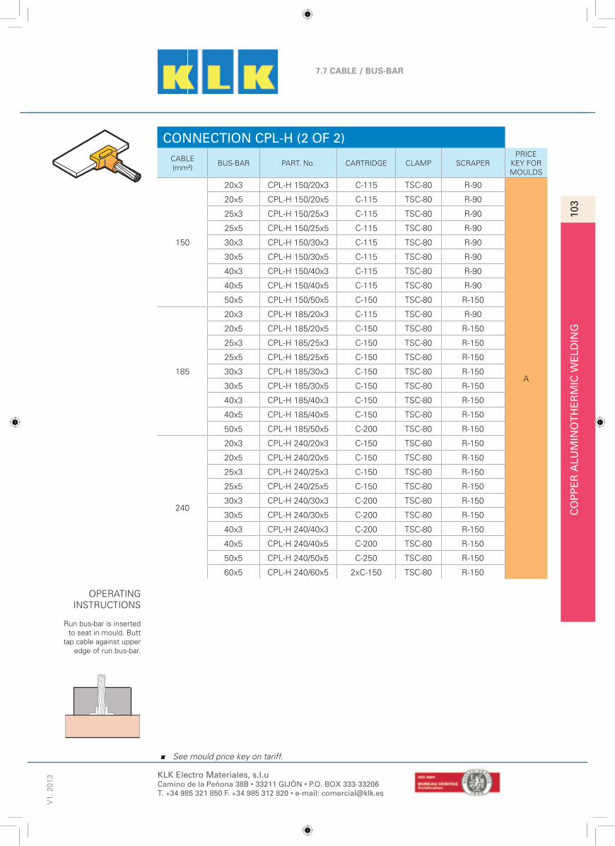
CO
PP
ER
ALU
MIN
OT
HE
RM
IC W
ELD
ING
103
7.7 CABLE / BUS-BAR
V1.
201
338
See mould price key on tariff.
KLK Electro Materiales, s.l.uCamino de la Peñona 38B • 33211 GIJÓN • P.O. BOX 333-33206T. +34 985 321 850 F. +34 985 312 820 • e-mail: [email protected]
CONNECTION CPL-H (2 OF 2)CABLE(mm²)
BUS-BAR PART. No. CARTRIDGE CLAMP SCRAPERPRICE
KEY FORMOULDS
150
20x3 CPL-H 150/20x3 C-115 TSC-80 R-90
A
20x5 CPL-H 150/20x5 C-115 TSC-80 R-90
25x3 CPL-H 150/25x3 C-115 TSC-80 R-90
25x5 CPL-H 150/25x5 C-115 TSC-80 R-90
30x3 CPL-H 150/30x3 C-115 TSC-80 R-90
30x5 CPL-H 150/30x5 C-115 TSC-80 R-90
40x3 CPL-H 150/40x3 C-115 TSC-80 R-90
40x5 CPL-H 150/40x5 C-115 TSC-80 R-90
50x5 CPL-H 150/50x5 C-150 TSC-80 R-150
185
20x3 CPL-H 185/20x3 C-115 TSC-80 R-90
20x5 CPL-H 185/20x5 C-150 TSC-80 R-150
25x3 CPL-H 185/25x3 C-150 TSC-80 R-150
25x5 CPL-H 185/25x5 C-150 TSC-80 R-150
30x3 CPL-H 185/30x3 C-150 TSC-80 R-150
30x5 CPL-H 185/30x5 C-150 TSC-80 R-150
40x3 CPL-H 185/40x3 C-150 TSC-80 R-150
40x5 CPL-H 185/40x5 C-150 TSC-80 R-150
50x5 CPL-H 185/50x5 C-200 TSC-80 R-150
240
20x3 CPL-H 240/20x3 C-150 TSC-80 R-150
20x5 CPL-H 240/20x5 C-150 TSC-80 R-150
25x3 CPL-H 240/25x3 C-150 TSC-80 R-150
25x5 CPL-H 240/25x5 C-150 TSC-80 R-150
30x3 CPL-H 240/30x3 C-200 TSC-80 R-150
30x5 CPL-H 240/30x5 C-200 TSC-80 R-150
40x3 CPL-H 240/40x3 C-200 TSC-80 R-150
40x5 CPL-H 240/40x5 C-200 TSC-80 R-150
50x5 CPL-H 240/50x5 C-250 TSC-80 R-150
60x5 CPL-H 240/60x5 2xC-150 TSC-80 R-150
OPERATINGINSTRUCTIONS
Run bus-bar is insertedto seat in mould. Butt
tap cable against upperedge of run bus-bar.

CO
PP
ER
ALU
MIN
OT
HE
RM
IC W
ELD
ING
104
7.7 CABLE / BUS-BARV
1. 2
013
39
See mould price key on tariff.
KLK Electro Materiales, s.l.uCamino de la Peñona 38B • 33211 GIJÓN • P.O. BOX 333-33206T. +34 985 321 850 F. +34 985 312 820 • e-mail: [email protected]
CONNECTION CPL-T (1 OF 2)
DIMENSION
CABLE(mm²)
BUS-BAR PART. No. CARTRIDGE CLAMP SCRAPERPRICE
KEY FORMOULDS
25
20x2 CPL-T 25/20x2 C-45* TSC-80 R-45
A
20x3 CPL-T 25/20x3 C-45* TSC-80 R-45
20x5 CPL-T 25/20x5 C-45* TSC-80 R-45
25x3 CPL-T 25/25x3 C-45* TSC-80 R-45
35
20x2 CPL-T 35/20x2 C-45* TSC-80 R-45
20x3 CPL-T 35/20x3 C-45* TSC-80 R-45
20x5 CPL-T 35/20x5 C-65 TSC-80 R-45
25x3 CPL-T 35/25x3 C-65 TSC-80 R-45
50
20x2 CPL-T 50/20x2 C-45 TSC-80 R-45
20x3 CPL-T 50/20x3 C-65 TSC-80 R-45
20x5 CPL-T 50/20x5 C-65 TSC-80 R-45
25x3 CPL-T 50/25x3 C-90 TSC-80 R-90
25x5 CPL-T 50/25x5 C-90 TSC-80 R-90
70
20x2 CPL-T 70/20x2 C-65 TSC-80 R-45
20x3 CPL-T 70/20x3 C-90 TSC-80 R-90
20x5 CPL-T 70/20x5 C-90 TSC-80 R-90
25x3 CPL-T 70/25x3 C-90 TSC-80 R-90
25x5 CPL-T 70/25x5 C-115 TSC-80 R-90
30x3 CPL-T 70/30x3 C-115 TSC-80 R-90
95
20x3 CPL-T 95/20x3 C-115 TSC-80 R-90
20x5 CPL-T 95/20x5 C-150 TSC-80 R-150
25x3 CPL-T 95/25x3 C-150 TSC-80 R-150
25x5 CPL-T 95/25x5 C-150 TSC-80 R-150
30x3 CPL-T 95/30x3 C-150 TSC-80 R-150
30x5 CPL-T 95/30x5 C-150 TSC-80 R-150
40x3 CPL-T 95/40x3 C-150 TSC-80 R-150
40x5 CPL-T 95/40x5 C-150 TSC-80 R-150
50x5 CPL-T 95/50x5 C-200 TSC-80 R-150
OPERATINGINSTRUCTIONS
Butt tap bus-bar againstside of run cable.
Possibility of using mini moulds for cartridges C-45 or smaller, with clamp TSC-50 and scrapper R-M.

CO
PP
ER
ALU
MIN
OT
HE
RM
IC W
ELD
ING
105
7.7 CABLE / BUS-BAR
V1.
201
340
See mould price key on tariff.
KLK Electro Materiales, s.l.uCamino de la Peñona 38B • 33211 GIJÓN • P.O. BOX 333-33206T. +34 985 321 850 F. +34 985 312 820 • e-mail: [email protected]
CONNECTION CPL-T (2 OF 2)CABLE(mm²)
BUS-BAR PART. No. CARTRIDGE CLAMP SCRAPERPRICE
KEY FORMOULDS
120
20x3 CPL-T 120/20x3 C-150 TSC-80 R-150
A
20x5 CPL-T 120/20x5 C-150 TSC-80 R-150
25x3 CPL-T 120/25x3 C-150 TSC-80 R-150
25x5 CPL-T 120/25x5 C-150 TSC-80 R-150
30x3 CPL-T 120/30x3 C-200 TSC-80 R-150
30x5 CPL-T 120/30x5 C-200 TSC-80 R-150
40x3 CPL-T 120/40x3 C-200 TSC-80 R-150
40x5 CPL-T120/40x5 C-200 TSC-80 R-150
50x5 CPL-T 120/50x5 C-250 TSC-80 R-150
60x5 CPL-T 120/60x5 2xC-150 TSC-100 R-750 F
150
20x5 CPL-T 150/20x5 C-200 TSC-80 R-150
A
25x3 CPL-T 150/25x3 C-200 TSC-80 R-150
25x5 CPL-T 150/25x5 C-200 TSC-80 R-150
30x3 CPL-T 150/30x3 C-200 TSC-80 R-150
30x5 CPL-T 150/30x5 C-200 TSC-80 R-150
40x3 CPL-T 150/40x3 C-250 TSC-80 R-150
40x5 CPL-T150/40x5 C-250 TSC-80 R-150
50x5 CPL-T 150/50x5 2xC-150 TSC-80 R-150
60x5 CPL-T 150/60x5 2xC-150 TSC-100 R-750 F
185
25x5 CPL-T 185/25x5 C-200 TSC-80 R-150
A
30x3 CPL-T 185/30x3 C-200 TSC-80 R-150
30x5 CPL-T 185/30x5 C-200 TSC-80 R-150
40x3 CPL-T 185/40x3 C-250 TSC-80 R-150
40x5 CPL-T185/40x5 C-250 TSC-80 R-150
50x5 CPL-T 185/50x5 2xC-150 TSC-80 R-150
60x5 CPL-T 185/60x5 2xC-150 TSC-100 R-750 F
240
25x5 CPL-T 240/25x5 C-250 TSC-80 R-150
A
30x3 CPL-T 240/30x3 C-250 TSC-80 R-150
30x5 CPL-T 240/30x5 C-250 TSC-80 R-150
40x3 CPL-T 240/40x3 2xC-150 TSC-80 R-150
40x5 CPL-T 240/40x5 2xC-150 TSC-80 R-150
50x5 CPL-T 240/50x5 2xC-150 TSC-80 R-150
60x5 CPL-T 240/60x5 2xC-200 TSC-100 R-750 F
OPERATINGINSTRUCTIONS
Butt tap bus-bar againstside of run cable.

CO
PP
ER
ALU
MIN
OT
HE
RM
IC W
ELD
ING
106
7.7 CABLE / BUS-BARV
1. 2
013
41
See mould price key on tariff.
KLK Electro Materiales, s.l.uCamino de la Peñona 38B • 33211 GIJÓN • P.O. BOX 333-33206T. +34 985 321 850 F. +34 985 312 820 • e-mail: [email protected]
CONNECTION CPL-L (1 OF 2)
DIMENSION
CABLE(mm²)
BUS-BAR PART. No. CARTRIDGE CLAMP SCRAPERPRICE
KEY FORMOULDS
2520x2 CPL-L 25/20x2 C-32* TSC-80 R-45
B
20x3 CPL-L 25/20x3 C-45* TSC-80 R-45
35
20x2 CPL-L 35/20x2 C-45* TSC-80 R-45
20x3 CPL-L 35/20x3 C-45* TSC-80 R-45
20x5 CPL-L 35/20x5 C-45* TSC-80 R-45
25x3 CPL-L 35/25x3 C-45* TSC-80 R-45
50
20x2 CPL-L 50/20x2 C-45* TSC-80 R-45
20x3 CPL-L 50/20x3 C-45* TSC-80 R-45
20x5 CPL-L 50/20x5 C-65 TSC-80 R-45
25x3 CPL-L 50/25x3 C-65 TSC-80 R-45
70
20x2 CPL-L 70/20x2 C-45* TSC-80 R-45
20x3 CPL-L 70/20x3 C-65 TSC-80 R-45
20x5 CPL-L 70/20x5 C-65 TSC-80 R-45
25x3 CPL-L 70/25x3 C-90 TSC-80 R-90
25x5 CPL-L 70/25x5 C-90 TSC-80 R-90
95
20x2 CPL-L 95/20x2 C-65 TSC-80 R-45
20x3 CPL-L 95/20x3 C-90 TSC-80 R-90
20x5 CPL-L 95/20x5 C-90 TSC-80 R-90
25x3 CPL-L 95/25x3 C-90 TSC-80 R-90
25x5 CPL-L 95/25x5 C-115 TSC-80 R-90
30x3 CPL-L 95/30x3 C-115 TSC-80 R-90
120
20x3 CPL-L 120/20x3 C-115 TSC-80 R-90
20x5 CPL-L 120/20x5 C-115 TSC-80 R-90
25x3 CPL-L 120/25x3 C-115 TSC-80 R-90
25x5 CPL-L 120/25x5 C-115 TSC-80 R-90
30x3 CPL-L 120/30x3 C-115 TSC-80 R-90
30x5 CPL-L 120/30x5 C-115 TSC-80 R-90
40x3 CPL-L 120/40x3 C-115 TSC-80 R-90
40x5 CPL-L 120/40x5 C-115 TSC-80 R-90
OPERATINGINSTRUCTIONS
Butt ends ofcable and bus-bar
under centre of taphole.
Possibility of using mini moulds for cartridges C-45 or smaller, with clamp TSC-50 and scrapper R-M.

CO
PP
ER
ALU
MIN
OT
HE
RM
IC W
ELD
ING
107
7.7 CABLE / BUS-BAR
V1.
201
342
See mould price key on tariff.
KLK Electro Materiales, s.l.uCamino de la Peñona 38B • 33211 GIJÓN • P.O. BOX 333-33206T. +34 985 321 850 F. +34 985 312 820 • e-mail: [email protected]
CONNECTION CPL-L (2 OF 2)CABLE(mm²)
BUS-BAR PART. No. CARTRIDGE CLAMP SCRAPERPRICE
KEY FORMOULDS
150
20x3 CPL-L 150/20x3 C-115 TSC-80 R-90
B
20x5 CPL-L 150/20x5 C-115 TSC-80 R-90
25x3 CPL-L 150/25x3 C-115 TSC-80 R-90
25x5 CPL-L 150/25x5 C-115 TSC-80 R-90
30x3 CPL-L 150/30x3 C-115 TSC-80 R-90
30x5 CPL-L 150/30x5 C-115 TSC-80 R-90
40x3 CPL-L 150/40x3 C-115 TSC-80 R-90
40x5 CPL-L 150/40x5 C-115 TSC-80 R-90
50x5 CPL-L 150/50x5 C-150 TSC-80 R-150
185
20x3 CPL-L 185/20x3 C-115 TSC-80 R-90
20x5 CPL-L 185/20x5 C-150 TSC-80 R-150
25x3 CPL-L 185/25x3 C-150 TSC-80 R-150
25x5 CPL-L 185/25x5 C-150 TSC-80 R-150
30x3 CPL-L 185/30x3 C-150 TSC-80 R-150
30x5 CPL-L 185/30x5 C-150 TSC-80 R-150
40x3 CPL-L 185/40x3 C-150 TSC-80 R-150
40x5 CPL-L 185/40x5 C-150 TSC-80 R-150
50x5 CPL-L 185/50x5 C-200 TSC-80 R-150
240
20x3 CPL-L 240/20x3 C-150 TSC-80 R-150
20x5 CPL-L 240/20x5 C-150 TSC-80 R-150
25x3 CPL-L 240/25x3 C-150 TSC-80 R-150
25x5 CPL-L 240/25x5 C-150 TSC-80 R-150
30x3 CPL-L 240/30x3 C-200 TSC-80 R-150
30x5 CPL-L 240/30x5 C-200 TSC-80 R-150
40x3 CPL-L 240/40x3 C-200 TSC-80 R-150
40x5 CPL-L 240/40x5 C-200 TSC-80 R-150
50x5 CPL-L 240/50x5 C-250 TSC-80 R-150
60x5 CPL-L 240/60x5 2xC-150 TSC-100 R-750 F
OPERATINGINSTRUCTIONS
Butt ends ofcable and bus-bar
under centre of taphole.

CO
PP
ER
ALU
MIN
OT
HE
RM
IC W
ELD
ING
108
7.8 BUS-BAR / BUS-BARV
1. 2
013
43
See mould price key on tariff.
KLK Electro Materiales, s.l.uCamino de la Peñona 38B • 33211 GIJÓN • P.O. BOX 333-33206T. +34 985 321 850 F. +34 985 312 820 • e-mail: [email protected]
OPERATINGINSTRUCTIONS
End of bus-bar less than30 mm wide must be
cut in “V” undercentre tap holes (S) 5
to 6 mm. Bus-barwider than 30 mm(S)
10 to 12 mm.
CONNECTION PL-LV
DIMENSION
BUS-BARMOULD
(PART. No.)CARTRIDGE CLAMP SCRAPER
PRICEKEY FORMOULDS
20x2 PL-LV 20x2 C-45* TSC-80 R-45
A
20x3 PL-LV 20x3 C-45* TSC-80 R-45
20x5 PL-LV 20x5 C-65 TSC-80 R-45
25x3 PL-LV 25x3 C-65 TSC-80 R-45
25x5 PL-LV 25x5 C-90 TSC-80 R-90
30x3 PL-LV 30x3 C-90 TSC-80 R-90
30x5 PL-LV 30x5 C-115 TSC-80 R-90
40x3 PL-LV 40x3 C-115 TSC-80 R-90
40x5 PL-LV 40x5 C-150 TSC-80 R-150B
50x5 PL-LV 50x5 C-200 TSC-80 R-150
60x5 PL-LV 60x5 2xC-150 TSC-100 R-750 E
S
Possibility of using mini moulds for cartridges C-45 or smaller, with clamp TSC-50 and scrapper R-M.

CO
PP
ER
ALU
MIN
OT
HE
RM
IC W
ELD
ING
109
7.8 BUS-BAR / BUS-BAR
V1.
201
344
See mould price key on tariff.
KLK Electro Materiales, s.l.uCamino de la Peñona 38B • 33211 GIJÓN • P.O. BOX 333-33206T. +34 985 321 850 F. +34 985 312 820 • e-mail: [email protected]
OPERATINGINSTRUCTIONS
End of bus-bar less than30 mm wide must be cut
in “V” under centre tapholes (S) 5 to 6 mm.
Busbarwider than 30 mm(S)
10 to 12 mm.
CONNECTION PL-ARI
DIMENSION
BUS-BARMOULD
(PART. No.)CARTRIDGE CLAMP SCRAPER
PRICEKEY FORMOULDS
20x2 PL-ARI 20x2 C-45* TSC-80 R-45
A
20x3 PL-ARI 20x3 C-45* TSC-80 R-45
20x5 PL-ARI 20x5 C-65 TSC-80 R-45
25x3 PL-ARI 25x3 C-65 TSC-80 R-45
25x5 PL-ARI 25x5 C-90 TSC-80 R-90
30x3 PL-ARI 30x3 C-90 TSC-80 R-90
30x5 PL-ARI 30x5 C-115 TSC-80 R-90
40x3 PL-ARI 40x3 C-115 TSC-80 R-90
40x5 PL-ARI 40x5 C-150 TSC-80 R-150B
50x5 PL-ARI 50x5 C-200 TSC-80 R-150
60x5 PL-ARI 60x5 2xC-150 TSC-100 R-750 E
S
Possibility of using mini moulds for cartridges C-45 or smaller, with clamp TSC-50 and scrapper R-M.

CO
PP
ER
ALU
MIN
OT
HE
RM
IC W
ELD
ING
110
7.8 BUS-BAR / BUS-BARV
1. 2
013
45
See mould price key on tariff.
KLK Electro Materiales, s.l.uCamino de la Peñona 38B • 33211 GIJÓN • P.O. BOX 333-33206T. +34 985 321 850 F. +34 985 312 820 • e-mail: [email protected]
OPERATINGINSTRUCTIONS
Insert the end of tapbus-bar even with upper
edge of run bus-bar.
CONNECTION PL-TV
DIMENSION
BUS-BARMOULD
(PART. No.)CARTRIDGE CLAMP SCRAPER
PRICEKEY FORMOULDS
20x2 PL-TV 20x2 C-45* TSC-80 R-45
A
20x3 PL-TV 20x3 C-65 TSC-80 R-45
20x5 PL-TV 20x5 C-65 TSC-80 R-45
25x3 PL-TV 25x3 C-90 TSC-80 R-90
25x5 PL-TV 25x5 C-90 TSC-80 R-90
30x3 PL-TV 30x3 C-90 TSC-80 R-90
30x5 PL-TV 30x5 C-115 TSC-80 R-90
40x3 PL-TV 40x3 C-115 TSC-80 R-90
40x5 PL-TV 40x5 C-150 TSC-80 R-150B
50x5 PL-TV 50x5 C-200 TSC-80 R-150
60x5 PL-TV 60x5 2xC-150 TSC-100 R-750 E
Possibility of using mini moulds for cartridges C-45 or smaller, with clamp TSC-50 and scrapper R-M.

CO
PP
ER
ALU
MIN
OT
HE
RM
IC W
ELD
ING
111
7.8 BUS-BAR / BUS-BAR
V1.
201
346
See mould price key on tariff.
KLK Electro Materiales, s.l.uCamino de la Peñona 38B • 33211 GIJÓN • P.O. BOX 333-33206T. +34 985 321 850 F. +34 985 312 820 • e-mail: [email protected]
OPERATINGINSTRUCTIONS
The ends of bus-bars ofup to 6 mm thick must
be separated (S) 5-6mm. in the centre of thetap hole. Bus-bar thicker
than 6 mm (S)10-12mm.
CONNECTION PL-V
DIMENSION
BUS-BARMOULD
(PART. No.)CARTRIDGE CLAMP SCRAPER
PRICEKEY FORMOULDS
20x2 PL-V 20x2 C-65 TSC-80 R-45B
20x3 PL-V 20x3 C-65 TSC-80 R-45
20x5 PL-V 20x5 C-90 TSC-80 R-90
D25x3 PL-V 25x3 C-90 TSC-80 R-90
25x5 PL-V 25x5 C-115 TSC-80 R-90
30x3 PL-V 30x3 C-115 TSC-80 R-90
30x5 PL-V 30x5 C-150 TSC-80 R-150
H40x3 PL-V 40x3 C-150 TSC-80 R-150
40x5 PL-V 40x5 C-200 TSC-80 R-150
50x5 PL-V 50x5 C-250 TSC-80 R-150
60x5 PL-V 60x5 2xC-150 TSC-100 R-750 J
S

CO
PP
ER
ALU
MIN
OT
HE
RM
IC W
ELD
ING
112
7.8 BUS-BAR / BUS-BARV
1. 2
013
47
See mould price key on tariff.
KLK Electro Materiales, s.l.uCamino de la Peñona 38B • 33211 GIJÓN • P.O. BOX 333-33206T. +34 985 321 850 F. +34 985 312 820 • e-mail: [email protected]
CONNECTION PL-TS
DIMENSION
BUS-BARMOULD
(PART. No.)CARTRIDGE CLAMP SCRAPER
PRICEKEY FORMOULDS
20x2 PL-TS 20x2 C-115 TSC-80 R-90
D
20x3 PL-TS 20x3 C-115 TSC-80 R-90
20x5 PL-TS 20x5 C-150 TSC-80 R-150
25x3 PL-TS 25x3 C-150 TSC-80 R-150
25x5 PL-TS 25x5 C-200 TSC-80 R-150
30x3 PL-TS 30x3 C-200 TSC-80 R-150
30x5 PL-TS 30x5 C-250 TSC-80 R-150
40x3 PL-TS 40x3 C-250 TSC-80 R-150
40x5 PL-TS 40x5 2xC-150 TSC-100 R-750
I50x5 PL-TS 50x5 2xC-200 TSC-100 R-750
60x5 PL-TS 60x5 2xC-250 TSC-100 R-750
S
OPERATINGINSTRUCTIONS
Leave a gap of(S) 5-6 mm between
the tap bus-bar and therun bus-bar. Secure
them with backing plateattachment.

CO
PP
ER
ALU
MIN
OT
HE
RM
IC W
ELD
ING
113
7.8 BUS-BAR / BUS-BAR
V1.
201
348
See mould price key on tariff.
KLK Electro Materiales, s.l.uCamino de la Peñona 38B • 33211 GIJÓN • P.O. BOX 333-33206T. +34 985 321 850 F. +34 985 312 820 • e-mail: [email protected]
OPERATINGINSTRUCTIONS
Insert end of tap bus-barup to the centre of the taphole. Tab bus-bar must beat least 70 mm parallel to
the run bus-bar.
CONNECTION PL-DP
DIMENSION
BUS-BARMOULD
(PART. No.)CARTRIDGE CLAMP SCRAPER
PRICEKEY FORMOULDS
20x2 PL-DP 20x2 C-90 TSC-80 R-90B
20x3 PL-DP 20x3 C-90 TSC-80 R-90
20x5 PL-DP 20x5 C-90 TSC-80 R-90
C
25x3 PL-DP 25x3 C-90 TSC-80 R-90
25x5 PL-DP 25x5 C-90 TSC-80 R-90
30x3 PL-DP 30x3 C-115 TSC-80 R-90
30x5 PL-DP 30x5 C-115 TSC-80 R-90
40x3 PL-DP 40x3 C-115 TSC-80 R-90
40x5 PL-DP 40x5 C-200 TSC-80 R-150
50x5 PL-DP 50x5 C-200 TSC-80 R-150
60x5 PL-DP 60x5 2xC-200 TSC-100 R-750 I
70

CO
PP
ER
ALU
MIN
OT
HE
RM
IC W
ELD
ING
114
7.8 BUS-BAR / BUS-BARV
1. 2
013
49
See mould price key on tariff.
KLK Electro Materiales, s.l.uCamino de la Peñona 38B • 33211 GIJÓN • P.O. BOX 333-33206T. +34 985 321 850 F. +34 985 312 820 • e-mail: [email protected]
OPERATINGINSTRUCTIONS
Bus-bar up to 3 mmthick must be separated
(S) 3 mm in the centre ofthe tap hole. Bus-bars
thicker than 3 mm mustbe separated (S) 5-6
mm.
CONNECTION PL-LH
DIMENSION
BUS-BARMOULD
(PART. No.)CARTRIDGE CLAMP SCRAPER
PRICEKEY FORMOULDS
20x2 PL-LH 20x2 C-45* TSC-80 R-45
B
20x3 PL-LH 20x3 C-45* TSC-80 R-45
20x5 PL-LH 20x5 C-65 TSC-80 R-45
25x3 PL-LH 25x3 C-65 TSC-80 R-45
25x5 PL-LH 25x5 C-90 TSC-80 R-90
30x3 PL-LH 30x3 C-90 TSC-80 R-90
30x5 PL-LH 30x5 C-115 TSC-80 R-90
40x3 PL-LH 40x3 C-150 TSC-80 R-150
40x5 PL-LH 40x5 C-150 TSC-80 R-150
50x5 PL-LH 50x5 C-200 TSC-80 R-150
60x5 PL-LH 60x5 2xC-150 TSC-100 R-750 F
S
Possibility of using mini moulds for cartridges C-45 or smaller, with clamp TSC-50 and scrapper R-M.

CO
PP
ER
ALU
MIN
OT
HE
RM
IC W
ELD
ING
115
7.8 BUS-BAR / BUS-BAR
V1.
201
350
See mould price key on tariff.
KLK Electro Materiales, s.l.uCamino de la Peñona 38B • 33211 GIJÓN • P.O. BOX 333-33206T. +34 985 321 850 F. +34 985 312 820 • e-mail: [email protected]
OPERATINGINSTRUCTIONS
Tap bus-bars of up to 6mm thick must be
separated (S) 5-6 mmfrom the run bus bar.
Busbarthicker than 6 mm
must be separated (S)10mm.
CONNECTION PL-TH
DIMENSION
BUS-BARMOULD
(PART. No.)CARTRIDGE CLAMP SCRAPER
PRICEKEY FORMOULDS
20x2 PL-TH 20x2 C-45* TSC-80 R-45
B
20x3 PL-TH 20x3 C-45* TSC-80 R-45
20x5 PL-TH 20x5 C-65 TSC-80 R-45
25x3 PL-TH 25x3 C-65 TSC-80 R-45
25x5 PL-TH 25x5 C-90 TSC-80 R-90
30x3 PL-TH 30x3 C-90 TSC-80 R-90
30x5 PL-TH 30x5 C-115 TSC-80 R-90
40x3 PL-TH 40x3 C-150 TSC-80 R-150
40x5 PL-TH 40x5 C-150 TSC-80 R-150
50x5 PL-TH 50x5 C-200 TSC-80 R-150
60x5 PL-TH 60x5 2xC-150 TSC-100 R-750 F
S
Possibility of using mini moulds for cartridges C-45 or smaller, with clamp TSC-50 and scrapper R-M.

CO
PP
ER
ALU
MIN
OT
HE
RM
IC W
ELD
ING
116
7.8 BUS-BAR / BUS-BARV
1. 2
013
51
See mould price key on tariff.
KLK Electro Materiales, s.l.uCamino de la Peñona 38B • 33211 GIJÓN • P.O. BOX 333-33206T. +34 985 321 850 F. +34 985 312 820 • e-mail: [email protected]
OPERATINGINSTRUCTIONS
Place bus-bar in themould slots.
CONNECTION PL-X
DIMENSION
BUS-BARMOULD
(PART. No.)CARTRIDGE CLAMP SCRAPER
PRICEKEY FORMOULDS
20x2 PL-X 20x2 C-45* TSC-80 R-45
B
20x3 PL-X 20x3 C-65 TSC-80 R-45
20x5 PL-X 20x5 C-65 TSC-80 R-45
25x3 PL-X 25x3 C-65 TSC-80 R-45
25x5 PL-X 25x5 C-90 TSC-80 R-90
30x3 PL-X 30x3 C-90 TSC-80 R-90
30x5 PL-X 30x5 C-115 TSC-80 R-90
40x3 PL-X 40x3 C-115 TSC-80 R-90
40x5 PL-X 40x5 C-150 TSC-80 R-150
50x5 PL-X 50x5 C-200 TSC-80 R-150
60x5 PL-X 60x5 C-250 TSC-80 R-150
Possibility of using mini moulds for cartridges C-45 or smaller, with clamp TSC-50 and scrapper R-M.

©
®
The LsVIP KLK-weld Ignition Procedure is the best solution to ignite the aluminothermic welding charges from the point of view of safety and cleanliness, as it prevents spattering from the crucible-mould during the aluminothermic reaction, minimizes smoke emissions and, furthermore, it enables the charge to be ignited at a certain distance from the mould, using the KLK-weld Remote Ignition Device.
IGNITION PROCEDURE LsVIP
Ignition procedure for aluminothermic welding charges for electrical connections
Camino de la Peñona, 38-B33211 Gijón (Asturias) · Spain
Tel. +34 985 321 850Fax. +34 985 312 820
KLK-USA Co.(dba Dwight & Wilson Co.)
30 Interstate driveP.O. Box 363 Napoleon, OH · 43545 USA
Phone. +1 419 591 3778Fax. +1 419 599 [email protected]
KLK Electro Materiales, S.A.C/ Rosario Pino, Nº18, 4º - 7ª
28020 Madrid · SpainTel. +34 915 709 692 Fax. +34 915 713 540
EKE Electra-KLK Europe, S.à.r.l.Z.A. de L’Europe, 6 rue de l’Orge
68920 Wintzenheim Logelbach · FranceTel. +33 (0) 389 201 730 Fax. +33 (0) 389 201 731
www.klk.es

•••
®
The special lid used in the Ignition Procedure can be used either with the standard flint igniter or with the KLK-weld Remote Ignition Device. The same applies to the cartridges, ignition powder, and the other welding accessories, thus there is a complete versatility to use either of the two ignition options.
IGNITION PROCEDURE LsVIP••• EASY AND QUICK TO USE:
The connections achieved using the KLK-weld welding procedures, and in particular those achieved after using the LsVIP Ignition Procedure, are connections with a very high electrical conductivity, equal or greater to that of the welded conductor.
The KLK-weld Remote Ignition Device includes sufficient cable to allow the charge to be ignited at a certain distance from the mould where the reaction takes place. It only requires two standard batteries and it includes warning lights that indicate when the batteries are dead or if the fuse is properly inserted into the clamp.
For each ignition using the KLK-weld Remote Ignition Device it is also necessary to use a fuse, one end of which is inserted into the device clamp, the other end into the lid seat made for this purpose. The fuses are the only additional consumables for the remote ignition procedure.The LsVIP KLK-weld Ignition Procedure uses a special lid that
completely closes the mould crucible, so that it prevents spattering from the aluminothermic reaction. But at the same time it allows the release of overpressures within the crucible. Furthermore, the smoke emissions are much lower than in other ignition procedures.
Apart from the supplying of moulds with the special lid used in the procedure (the LsVIP moulds) a quick fastening special lid can also be supplied, this can be easily fitted onto a mould that uses the usual lid.
In this case, to use the special lid, it is sufficient to leave the usual lid open.
LsVIP: Low Smoke Versatile Ignition Procedure
Insert the fuse into the clamp of the device.
1
Pour the reserved ignition powder through the funnel shape
opening in the lid.
4
Pour the welding and the ignition powder into the crucible,
reserving a small amount of the ignition powder.
2
Partially open the upper part of the lid and place the fuse in its seat.
3
If the option chosen is remote ignition, move away from
the mould as desiredand press the button.
5If the option chosen is the flint igniter, put it close to the funnel
shape opening in the lid and pull the trigger.
6

KLK Electro Materiales, s.l.uCamino de la Peñona 38B • 33211 GIJÓN • P.O. BOX 333-33206T. +34 985 321 850 F. +34 985 312 820 • e-mail: [email protected]
V1.
201
312
0A
DVA
NTA
GE
S O
F T
HE
LS
VIP
PR
OC
EU
DR
E
ADVANTAGES OF THE LsVIP PROCEDURE
1.- KLK’s Remote ignition (LsVIP) is performed with the same cartridges and it is not necessary to have another reference of special cartridges. Our cartridges keep both powders separated yet together in the same container, which prevents the user from forgetting the ignition powder.
2.- It is possible to use the same moulds used for all the other welding works, only the lid changes, as our moulds have interchangeable lids. Distance welding is possible, safe welding without splattering and traditional welding. If requesting mould with Ref. LsVIP the mould already includes the lid.
3.- Our ignition system allows igniting with remote control and with igniter.
4.- Our remote ignition system uses an interchangeable lid for moulds which signifi -cantly reduces the smoke arising from the work and prevents spattering from the aluminothermic reaction.
5.- It is the best solution to comply with the most demanding safety requirements in the fi eld of aliminothermic welding.
6.- Due to versatility of LsVIP the users and clients do not need any more tools or new utensils and do not need to change the traditional ignition system and extend and modify their possible stock of material, and will never forget the ignition powder, allowing them to weld at all times.

©
®
The ELPA-Pipe KLK-weld procedure is the best solution for making the electrical connections of copper cable to steel pipe in order to give cathodic protection to the pipe, as the resulting weld has a low electrical resistivity and a high mechanical strength in the connection. This procedure does not change the structure of the steel pipe as the temperature never exceeds 450 ºC.
WELDING PROCEDURE ELPA-PIPE
Welding of electric copper cable to steel pipe
Camino de la Peñona, 38-B33211 Gijón (Asturias) · Spain
Tel. +34 985 321 850Fax. +34 985 312 820
KLK-USA Co.(dba Dwight & Wilson Co.)
30 Interstate driveP.O. Box 363 Napoleon, OH · 43545 USA
Phone. +1 419 591 3778Fax. +1 419 599 [email protected]
KLK Electro Materiales, S.A.C/ Rosario Pino, Nº18, 4º - 7ª
28020 Madrid · SpainTel. +34 915 709 692 Fax. +34 915 713 540
EKE Electra-KLK Europe, S.à.r.l.Z.A. de L’Europe, 6 rue de l’Orge
68920 Wintzenheim Logelbach · FranceTel. +33 (0) 389 201 730 Fax. +33 (0) 389 201 731
www.klk.es

®
The ELPA-Pipe KLK-weld procedure combines aluminothermic welding and braze- welding processes in which the latter partially uses the heat produced by the former. A ferritic steel plate is placed between the copper conductor and the pipe absorbing the thermal shock of the aluminothermic molten metal. As a result of this, the plate will be welded to the cable’s end. A tin-silver alloy on the pipe side of this plate makes the pipe/plate joint possible through the combination of the heat that melts this alloy and the strength of the device that pushes the plate to the pipe during the solidification process. The result is a fault free braze-weld
The procedure has two versions:
• The first version uses one-shot moulds and reusable fixing tools.
• The second version consists of one-shot moulds mounted on non-reusable fixing tools.
For both options, there is no need to completely unearth the pipes because the fixing devices do not encompass them. To make the welds, it is sufficient to uncover the top of the pipe.
Also, the same kit may be used with any size of pipe (greater than a minimum). It is also possible to supply kits that can be used with different sections of cable. The most common ones go from 10 mm2 to 70mm2.
As an option, the LsVIP (Low smoke Versatile Ignition Procedure) may be used. This allows safe distance to be kept during welding.
WELDING PROCEDURE ELPA-PIPE
THE ELPA-PIPE KLK-WELD KIT INCLUDES THE FOLLOWING PARTS:
EASY AND CONVENIENT USE
a Ceramic mould with a steel plate, sleeve for cable entrance, metal disc to seal the crucible draining hole, sealing joints, lid with fuse for the remote starting and, depending on the above mentioned version, a fixing device.
b Cartridge containing the welding and the ignition powder.
c Flux portion.
d Flare to ignite the powder.
e Additional sleeves to be used with other cable sections (as an option).
f User’s guide.
Remove protective insulation, grind and apply the flux to the area.
1
Finished weld.
Pour the welding and ignition powder into the mould and ignite.
4
Place the mould and activate the fixing device.
2
Insert the cable to the stop in the mould’s sleeve.
3
Break the mould and clean the weld.
7
As an option, the LsVIP (Low smoke Versatile Ignition Procedure) may be
used to ignite the powder.
5
Either the flint ignitor or the flare may be used to ignite the powder.
6
8

KLK Electro Materiales, s.l.uCamino de la Peñona 38B • 33211 GIJÓN • P.O. BOX 333-33206T. +34 985 321 850 F. +34 985 312 820 • e-mail: [email protected]
V1.
201
312
4A
DVA
NTA
GE
S O
F T
HE
ELP
A-P
IPE
KIT
ADVANTAGES OF THE ELPA-PIPE KIT
Advantages of the new welding procedure at low-temperature to make electrical connections of copper cable to steel pipe, in order to provide cathodic protection to the pipe.
The advantages of this low-temperature welding procedure which has the trade name of Elpa-Pipe, are listed below:
1. The connections achieved have excellent electric conductivity.
2. The connections achieved have high mechanical resistance.
3. The internal steel structure of the pipe is not altered.
4. Easy and fast to use.
5. Absolute reliability.
6. To weld it is not necessary to completely unbury the pipe, uncovering part of it is suffi cient.
7. Good price.
8. The same kit can be used on pipes of different diameters (please enquire).
9. Possibility of supplying kits that can be used with cables of different sections.
10. Possibility of remote ignition.
11. Possibility of using on active pipes without the need to cancel the supply or transport.

KLK Electro Materiales, s.l.uCamino de la Peñona 38B • 33211 GIJÓN • P.O. BOX 333-33206T. +34 985 321 850 F. +34 985 312 820 • e-mail: [email protected]
V1.
201
3
NOTES

KLK Electro Materiales, s.l.uCamino de la Peñona 38B • 33211 GIJÓN • P.O. BOX 333-33206T. +34 985 321 850 F. +34 985 312 820 • e-mail: [email protected]
V1.
201
3
NOTES


El procedimiento de soldadura ELPA-Tubo KLK-weld es el mejor procedimiento para realizar conexión eléctrica de cable de cobre a tubería de acero, con el fin de realizar protección catódica de esa tubería, pues se consigue una baja resistividad eléctrica y una alta resistencia mecánica en la conexión, todo ello sin afectar al acero de la tubería, pues la temperatura en la misma no supera los 450ºC.
PROCEDIMIENTO DE SOLDADURA ELPA-TUBO
Procedimiento de soldadura de conexiones eléctricas de cable de cobre a tubería de acero
Camino de la Peñona, 38-B33211 Gijón (Asturias) · Spain
Tel. +34 985 321 850Fax. +34 985 312 820
KLK-USA Co.(dba Dwight & Wilson Co.)
30 Interstate driveP.O. Box 363 Napoleon, OH · 43545 USA
Phone. +1 419 591 3778Fax. +1 419 599 [email protected]
KLK Electro Materiales, S.A.C/ Rosario Pino, Nº18, 4º - 7ª
28020 Madrid · SpainTel. +34 915 709 692 Fax. +34 915 713 540
EKE Electra-KLK Europe, S.à.r.l.Z.A. de L’Europe, 6 rue de l’Orge
68920 Wintzenheim Logelbach · FranceTel. +33 (0) 389 201 730 Fax. +33 (0) 389 201 731
www.klk.es©
®
RAILTECH BOUTET, Inc.
25 Interstate Drive P.O. Box 69
Napoleon, OH 43545 Phone. (419) 592-5050
Fax. (419) [email protected]
KLK Electro Materiales, S.L.UC/ Rosario Pino, Nº18, 4º - 7ª
28020 Madrid · SpainTel. +34 915 709 692 Fax. +34 915 713 540
EKE Electra-KLK Europe, S.à.r.l.Z.A. de L’Europe, 6 rue de l’Orge
68920 Wintzenheim Logelbach · FranceTel. +33 (0) 389 201 730 Fax. +33 (0) 389 201 731