earthwork & utilitiescontents.kocw.net/kocw/document/2015/gachon/kimjaecheol2/13.pdf · –...
TRANSCRIPT

단지계획 14강EARTHWORK & UTILITIES
1

PRESENTATION ORDER
2
I. Overview
• General process of earthworks
• Construction documents
II. Earthwork
• Earthwork
• Earth-moving machines
• Grading criteria
• Representing elevations
• Cut and fill calculations
• Profiles
• Grading plans
III. Utilities
• Storm drainage
– Elements of the system
– Flow of water
– Gradients
– System layout
– Computation of pipe size
– Culverts
• Sanitary drainage
– Sewage disposal
– Dry disposal
• Water supply
– Capacity
• Electric power
• Lighting
• Other utilities
• Solid waste
• Utility plan

3
I. Overview
• “Infrastructure” – pavements, curbs, foundations, grading, sewer
pipes, power lines – is the central concerns of site construction,
and their specification is the meat of the working drawings.
• Normal construction process: 1) Identify the accurate location
of property and construction boundaries; 2) Strip off the topsoil
from the working area and store in heaps; 3) Locate principle
structure (roads, buildings, underground utilities); 4) Lay
foundations and trench in pipes; 5) Complete major structures; 6)
Grade the exposed topsoil to its new shape; 7) Install the road
base & surfacing and above-ground features 8) Replace the
topsoil and put in new plant materials
• This normal process will often be modified
e.g.) When new grades are very different from the old ?
4
I. Overview
Construction documents
• Contents and preparation order of construction documents
1. Precise plan layout (layout of the roads and buildings in plan)
2. A profile of each road or other critical linear feature
3. Spot elevations of critical points & a grading plan
4. A plan layout of all utilities
5. A landscaping plan
6. A series of detailed drawings of street elements (manholes, inlets,
curbs, seats, lights, and walls)
7. A set of written specifications to control the quality and installation
• However, working details are not just the mechanical consequence of a
design idea. Designers should develop them in a looping and iterative
game

5
II. Earthwork
Earthwork
• Grading has a strong influence on cost, utility, and appearance of the
completed project
• Use of grade stakes
• The ratio of cut and filled earth volumes: This is only a first guess!!
1) Not compacted + 15~25%;
2) Compacted - 10%;
3) Normally, - 5%
Grade stakes
6
II. Earthwork
Earthwork
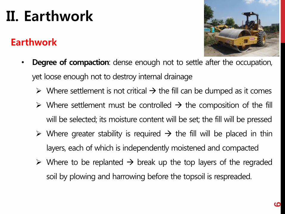
• Degree of compaction: dense enough not to settle after the occupation,
yet loose enough not to destroy internal drainage
Where settlement is not critical the fill can be dumped as it comes
Where settlement must be controlled the composition of the fill
will be selected; its moisture content will be set; the fill will be pressed
Where greater stability is required the fill will be placed in thin
layers, each of which is independently moistened and compacted
Where to be replanted break up the top layers of the regraded
soil by plowing and harrowing before the topsoil is respreaded.

7
II. Earthwork
Earthwork
• Other disturbances during the grading process (by surface erosion)
Valuable organic material is lost by mixing topsoil and subsoil
A loss of soil
The pollution of downstream rivers and ponds
• Countermeasures
dam at the lower edges of all newly graded areas with
temporary berms of earth
quick replanting
spraying new ground with water, seed, and liquid fertilizer

8
II. Earthwork
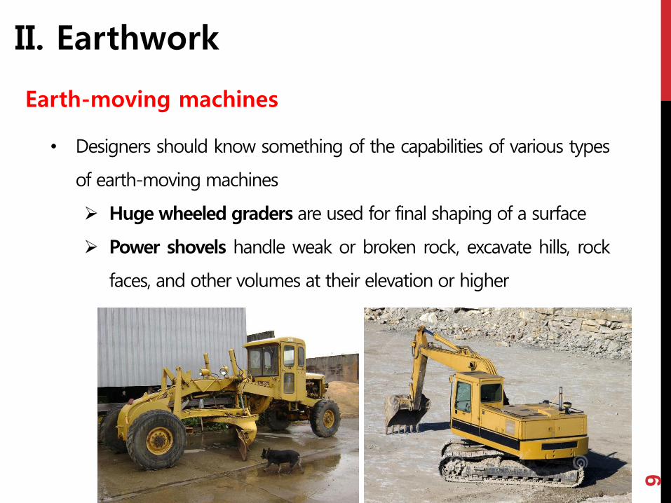
Earth-moving machines
• Designers should know something of the capabilities of various types
of earth-moving machines
Tracked bulldozers are used wherever a push or pulling force is
needed, have 3.5~6m turn radius, and work on slope up to 85%
Huge wheeled scrapers take up earth from their undersides and
carry it along to be released at will, can operate on slopes up to
60% longitudinal and 25% traverse
9
II. Earthwork
Earth-moving machines
• Designers should know something of the capabilities of various types
of earth-moving machines
Huge wheeled graders are used for final shaping of a surface
Power shovels handle weak or broken rock, excavate hills, rock
faces, and other volumes at their elevation or higher

10
II. Earthwork
Earth-moving machines
• Designers should know something of the capabilities of various types
of earth-moving machines
Draglines useful for large cuts and channels below the level of
the machine and for making valleys, mounds, slopes and banks
Rollers and scarifiers to compact or break up the ground
11
II. Earthwork
Earth-moving machines
• Cost rules for areas larger than 5 acres
Curves of new contours should not be sharper than the
minimum radii of the expected equipment
Equipment cannot work on too steep slopes or work
economically in confined spaces
Fussy shapes and shallow cuts and fills are to be avoided
Undulating hill and valley forms are cheaper than terracing
Repeated landforms are cheap

12
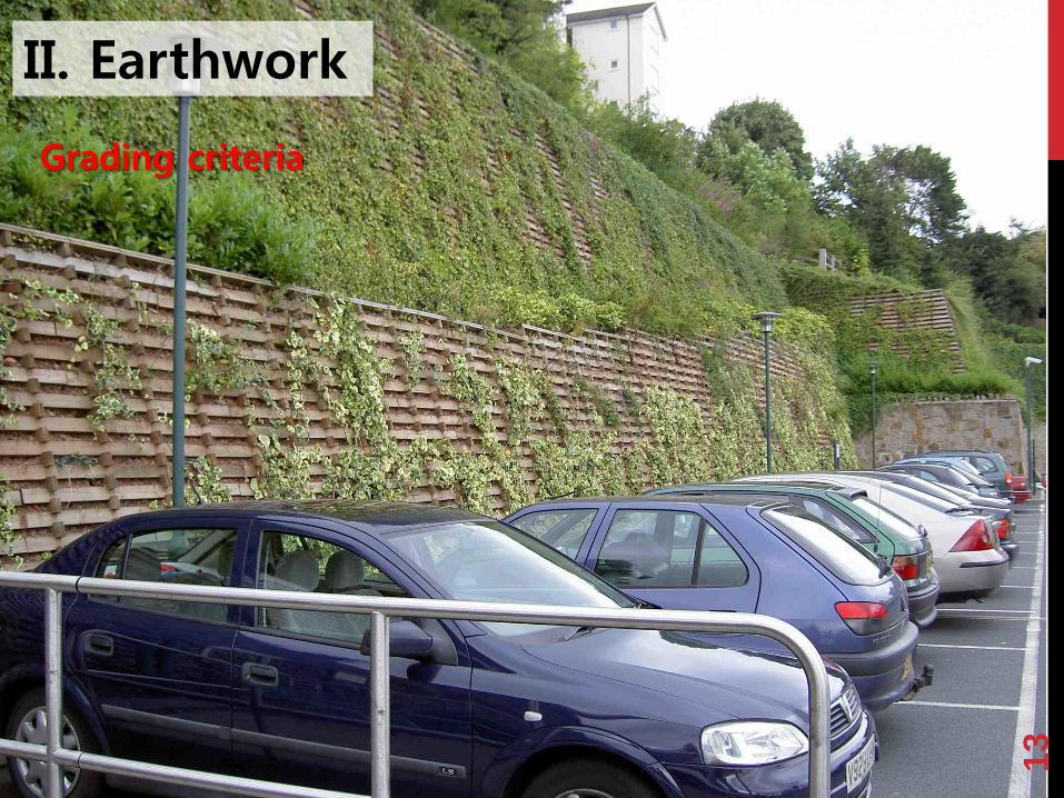
II. Earthwork
Grading criteria
• New grades are kept as close to preexisting grades as possible
• Agricultural value of the land should be conserved even in urban
development … one therefore avoids unnecessary, shallow cuts in
particular
• The basic criteria for any new surface are its fitness for the purposes of
its occupants and its ability to be maintained as part of a stable system
• Imagine acting and moving over it check it for its plant cover, for
erosion and for drainage
• Grass slopes … below 25% (ivy up to 100%); wet clay and silt … 30%; wet
sand … 80%↔ crib or terrace or drainage at its top might be helpful
13
II. Earthwork
Grading criteria

14
II. Earthwork
Grading criteria
• Drainage … water should flow away from buildings and roads, and not
be directed into valleys and swales not prepared for the additional flow
• To have a pleasing visual form (simple, smoothly curving, visually
stable), the new ground shape must be imagined from many
viewpoints … and mostly, it will be studied in a model
• Common difficulties in a grading plan: excessive or unbalanced cut
and fill; drainage pockets in the land, on the roads or against the sides
of buildings; steep grades; a poor visual or functional relation between
a building or a road and its surroundings; the destruction of existing
trees by changes in the ground level; the loss of good agricultural soil;
frequent use of expensive and undesirable steps and retaining walls

15
II. Earthwork
Representing elevations
• The new surface is usually represented by a drawing showing the new
contour lines in relation to the old ones, supplemented by spot
elevations at key points
• The new form as the best transition between the set of fixed points
(the roads, buildings, sewers and special landscape features) and the
existing land at the site boundaries or at the edge of construction
• The new form as a sculpture
• In either case, contour sketch are designer’s language and he must be
fluent

16
II. Earthwork
Representing elevations

17
II. Earthwork
Cut and fill calculations
• Methods of cut and fill calculation
Contour-area method
End-area method: used for a long, connected
can
Use of elevations at grid corners

18
II. Earthwork
Profiles
• The vertical dimension of the plan
• Begin with the design of the road profile
• The horizontal scale is that of the road layout; the vertical scale is
exaggerated ten times
• Draw a series of straight tangents over the profile of the existing
ground
• Search for a new line whose grades are neither too steep nor too flat,
minimizing and balancing cut and fill
• Then draw the necessary vertical curves at the intersections of the
tangents
• Profile vs. grading plan

19
II. Earthwork
Profiles

20
II. Earthwork
Grading plans
• Connect Spot elevations at other critical
points – such as … floors in the principle
buildings or those at the base of existing
trees to be saved (and roads) – with freehand
smooth curves
21
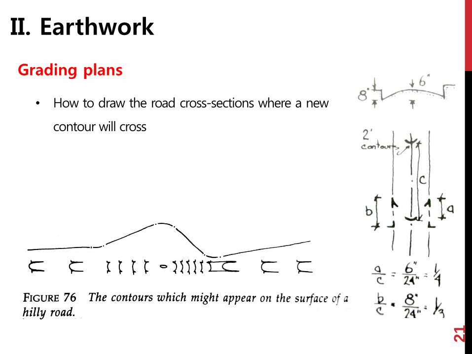
II. Earthwork
Grading plans
• How to draw the road cross-sections where a new
contour will cross

22
II. Earthwork
Grading plans
23
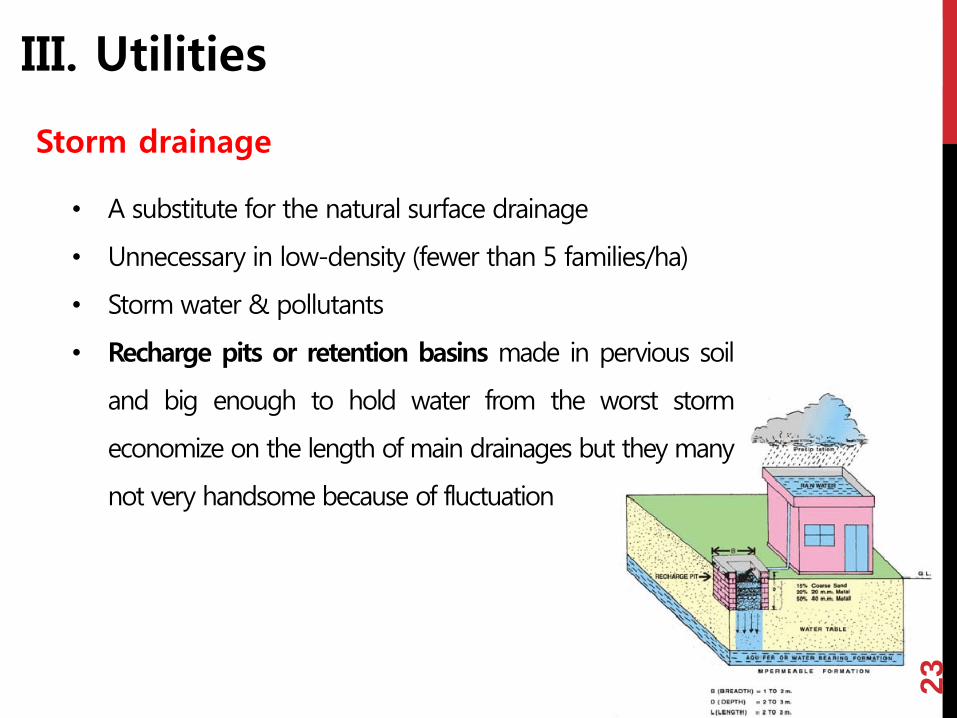
III. Utilities
Storm drainage
• A substitute for the natural surface drainage
• Unnecessary in low-density (fewer than 5 families/ha)
• Storm water & pollutants
• Recharge pits or retention basins made in pervious soil
and big enough to hold water from the worst storm
economize on the length of main drainages but they many
not very handsome because of fluctuation

24
III. Utilities
Storm drainage

25
III. Utilities
Storm drainage

26
III. Utilities
Storm drainage
• Heavy runoff from the development
1) overloads downstream channels
2) imposes cost for artificial drainage works
3) lowers the water table
• Underground drainage system’s problems: 1) expensive 2) cause
difficulties in the grading plan
• Ways to minimize the underground drainage system:
Low density development; decrease of paved surfaces; increase of
planted surfaces; careful grading to ensure gentle slopes and
positive flow; rely on ditches
• Separation of storm water drainage from sanitary drainage

27
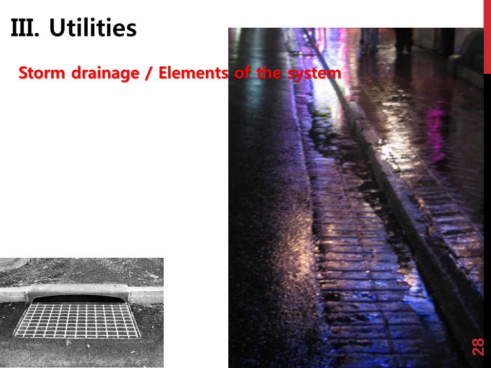
III. Utilities
Storm drainage / Elements of the system
• The storm system: a drainage surface (a set of open gutters and ditches);
a series of underground pipes made of vitrified clay; manholes; inlets
• Large sewers over 1m in diameter are made of concrete
• For all sizes of sewer lines, the radius is not less than 30m ( for
maintenance) and the vertical grade is constant
• Manholes – man-sized circular pits – are used to enter the lines for
inspection and maintenance … placed at the upper end of lines and at
every change in horizontal or vertical direction or curvature … place no
more than 100 to 150 m apart for cleaning apparatus
• Recharge manholes: designed to deliver storm water back to the ground
… made with porous sides and … set in pits filled with gravel
28
III. Utilities
Storm drainage / Elements of the system

29
III. Utilities
Storm drainage / Flow of water
• Keep the surface water moving but not so fast to cause erosion
• Allowable slopes depends on 1) volume of water 2) surface finish 3) the
amount of damage expected by local flooding
• Minimum grades: planted areas and broad paved areas 1%; streets and
other paved surfaces with exact elevations 0.5%; land within 3m from all
buildings 2%; Planted drainage swales 2% (no more than 10% or 5% if
the area drained is over 0.2 hectares); Lawns and grass bank maximum
25%; unmown planted banks maximum 50%
• The designer must be aware of the quantity of flow entering his site
from the outside and of how it may change in the future … any water
leaving his site should not be greater than before

30
III. Utilities
Storm drainage / Flow of water
• Surface flow will begin to cut small rivulets within 150m it should be
concentrated in man-made channels
• Check dams, paved channels or piped drains may be installed to
prevent erosion
• Gutter flow must be picked up at least once on each block, at the
lowest corner, or be carried under the crossroad in culvert
• Gutter flow should not run more than 250 to 300m, turn a sharp corner
or meet a sudden obstacle
• Inlets finally cut the flow

31
III. Utilities
Storm drainage / Flow of water

32
III. Utilities
Storm drainage / Gradients
• Sewer lines must be covered deeply enough to prevent breakage and
freezing but no more than 6m
• L:ine slope … minimum 0.3% (0.6m/s) … not over 3m/s
• Changes in slope can be made only at man holes

33
III. Utilities
Storm drainage / System layout
• The storm sewer system is initially laid out in plan, with the 1st inlets
located as far down the slopes as possible within the limit for open
gutter flow. Then, the pattern of converging sewers is arranged … to
minimize the length of line and the number of manholes
• The manholes must be in the R.O.W. but the sewer lines may run
through easements separate from the R.O.W.
• It is easier to draw the preliminary profile upward from the
discharge point

34
III. Utilities
Storm drainage / Computation of pipe size
• Required pipe size depends on the slope of the pipe; the volume to
be carried; the size of the area being drained; the coefficient of runoff
(0.9 for roofs and pavements, 0.1 for wooded land); intensity of storm
(“year of the storm” + the time since the storm began); retention basins
• The minimum diameter of a sewer that drains a street is 300mm
• The velocity of flow within any pipe should be between 3 and 0.6m/s
the slope of very large pipes vs. very small pipes?

35
III. Utilities
Storm drainage / Culverts
• Culvert: A short length of pipe inserted under a road or other barrier to
carry storm water or a small brook
• The gradient just below the outlet must be at least as steep as the
slope just above the inlet to prevent silting
• The size of culverts is calculated in the same way as the size of sewer
pipes

36
III. Utilities
Sanitary drainage
• “Sanitary” wastes, such as those from sinks and toilets, are kept out of
the storm drains
• Sanitary drainage is typically a converging system of manholes and
straight pipes of gentle horizontal curvature, leading to a disposal plant
• Continuous over large areas … sometimes pumping is needed …
Pumping is avoided if possible at the site planning scale
• The layout is rarely controlling in site planning
• Unlike storm sewers, sanitary sewers form a closed drainage system
• The branch lines leading to houses connect into the main all along its
course rather than just at manhole
37
III. Utilities
Sanitary drainage
• The street main must be set low enough to receive the house laterals …
at least 2m down and more where the land slopes down from the
street or … deep basement
• Minimum size of sanitary sewer: 200mm for main or laterals and
150mm for house branches

38
III. Utilities
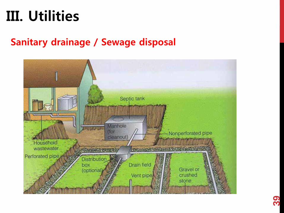
Sanitary drainage / Sewage disposal
• When a public disposal plant is not within reach, it is possible to
construct a private disposal plant and this plant should be set 100m
from any house and could be economically designed to serve 50~500
houses
• Where the soil is pervious and the ground water low, it is possible to give
each unit a septic tank discharging into an underground drain field …
Drain field must be kept 30m from any surface water or well, and should
not be heavily shaded, or crossed by any vehicles, or installed with a
slope over 15% … Absorption rate is important (Table 4)
• Private disposal plants vs. individual septic tanks
39
III. Utilities
Sanitary drainage / Sewage disposal

40
III. Utilities
Sanitary drainage / Sewage disposal
41
III. Utilities
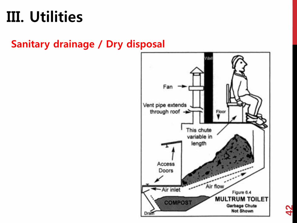
Sanitary drainage / Dry disposal
• The two water-borne systems are expensive, wasteful of a resource and
can pollute huge volumes of ground and surface water
• Alternative system using no or very little of water … the pit privy …
water table should be at least 7.5m below the bottom of the pit
(1~2m deep) … the pit must be at least 30m away and downhill from
any well … the soil not impermeable, nor yet so extremely permeable
… made tight for half a meter below … unlined below … the waste
materials of the privy filled is left underground for at least a year before
it is removed or used as fertilizer.
42
III. Utilities
Sanitary drainage / Dry disposal

43
III. Utilities
Sanitary drainage / Dry disposal
• More expensive aqua privy may be preferable where there is danger of
groundwater contamination … a water-tight tank, filled with water,
located directly under the toilet or squatting plate … connected to an
overflow drain … sludge falls to the bottom and scum floats on top.
The sludge I pumped very several years, while the scum is restrained by
a baffle from entering the overflow drain … 7 liters of water per person
(everyday) should be added to maintain the level and a sufficient
degree of dilution of the wastes … the tank must have a capacity of
about 120~150 liters for each person

44
III. Utilities
Sanitary drainage / Dry disposal

45
III. Utilities
Sanitary drainage / Dry disposal
• Anaerobic digester is a bulky sealed tank in which water, vegetable
waste, and excreta are held for 30~ 80days, producing methane gas
and a safe, fertilizing sludge … work only in a warm climate … best
suited to a tropical agricultural settlement
• Aerobic digester … decomposes the same mix of vegetable matter and
excreta in a large ventilated bin, from which odors and water vapors are
drawn off by a flue … A safe fertilizer can be removed from the
bottom of the bin in about 30~50days … No water is used; odors and
flies are controlled; no risk of disease; by-product is useful

46
III. Utilities
Sanitary drainage / Dry disposal

47
III. Utilities
Water supply
• Clean water is the most critical utility, a necessity even in the most
primitive settlement
• Water lines must be located in a public R.O.W.
• Water lines vs. Sewers
• Two basic distribution layouts
1. Treelike pattern – minimize length of line … cheapest
2. A loop or interconnected network – avoids the drop in pressure …
at the ends of long branches, and the difficulty of keeping the
dead-end pipes clear
• One most seriously affected by frost … laid under 1.5m(in New
England)
48
III. Utilities
Water supply
• Valves … placed in house branches where they leave the mains and in
the mains at points necessary to cut off section in the event of breaks
(no more than 300m apart)
• Fire hydrant … all parts of buildings within 100m from one or two
hydrants … not closer than 7.5m and preferably 15m from any
structure

49
III. Utilities
Water Supply / Capacity
• The minimum diameter for water mains is 150mm, or 200mm in high-
value areas
• In U.S. cities, average demand varies from 450 to 900 liters per capita
per day
• A private group water supply, composing of a well, ore group of wells, a
pump, and pressure or gravity tanks … can serve development of 50 to
500 houses … a threshold in cost at about 200 houses
• The principal cost is in the distribution system rather than in the pump
or well
• A large, professionally operated public water system is still the
preferable solution

50
III. Utilities
Water Supply / Capacity

51
III. Utilities
Electric power
• Power plants primary high-voltage lines transformers low-
voltage lines the points of use
• Secondary lines should be shorter than 120m
• Branching patterns vs. a loop distribution
• Overhead distribution vs. underground distribution (cost, breaks,
maintenance)
• Overhead system … a risk to building repairmen and adventurous
children … pole space 40m or less … esthetical problems … power poles
are useful for mounting street lights, telephone lines, signs, and
callboxes
52
III. Utilities
Lighting
• Standard mounting heights for lights are 9m over roadways at spacings
of 45~60m … 10 lux on arterial roads or large parking lots, or 5 lux on
local roads
• Lamps on walkways are normally 3.5m high … the critical factors are the
quality of the light and the psychological sense of safety. Thus shrubs,
recesses, doorways, steps, and intersections should be well lit … 50 lux
• Power and light poles are intrusions in the daytime visual scene
• Night lighting can structure a darkened landscape so that people find
their way and recognize the familiar daytime features
Symbolic landmarks vs. ordinary buildings
53
III. Utilities
Other utilities
• Gas is piped underground by a system similar to the water distribution
network … danger of leakage or explosion and so these lines are not
laid under or close to buildings except where they enter them, nor are
they put in the same trench with electric cable
• Telephone lines … overhead on the electric power poles or easily laid
in underground conduit

54
III. Utilities
Other utilities
• In case of central heating, the location of the heating plant is preferably
in the middle of the development but on low ground to facilitate the
return of condensate …
• The choice between central heating plants and individual ones depends
on the type and number of dwelling units, the attitude of residents,
maintenance costs, relative efficiency of plants, and the relative cost of
coal, gas, oil, and electricity
• The choice has an important effect on the site plan.
A central plant may be appropriate for 100~200 or more families
Individual plants need provision for the delivery and storage of fuel
(coal, oil, gas or electricity)

55
III. Utilities
Solid waste
• Organic material, combustible and noncombustible rubbish
• Use of incinerators; Separation for recycling; Burial of noncombustible
material
• For group collection stations, they are screened and drained
• For separate collection, a drained and protected area must be provided
for the waste cans, convenient to the dwelling unit and as close to the
curb as possible
• Compactors and duct systems

56
III. Utilities
Utility plans
• Once the grading plan has been completed, the layout of utilities is
made
• Usually, begin with the storm drainage
• Check if no critical problems of elevations or sizing will occur
• Check the layout of all utilities together and in three dimensions
• Where curves or grades permit, it is desirable to keep utilities in a
uniform location relative to the street, particularly underneath the
planting strip
• The layout of all utilities may be shown on one sheet, or it may be
more convenient for the storm drainage to be shown on the grading
plan