east anglia one north offshore windfarm cable statement
TRANSCRIPT

East Anglia ONE North Offshore Windfarm
Cable Statement Applicant: East Anglia ONE North Limited Document Reference: 7.1 SPR Reference: EA1N- DWF-ENV-REP-IBR-000409 Rev 01 Pursuant to APFP Regulation: 6(1)(b)(i) Date: October 2019 Revision: Version 1 Author: Shepherd and Wedderburn LLP
Prepared by: Checked by: Approved by: Shepherd and Wedderburn LLP 25 September 2019

East Anglia ONE North Offshore Windfarm
7.1 Cable Statement Page ii
Glossary of Acronyms
AIS Air insulated switchgear APFP Regulations Infrastructure Planning (Applications: Prescribed Forms and Procedures)
Regulations 2009 DCO Development Consent Order EPP Evidence Plan Process GIS Gas insulated switchgear HDD Horizontal Directional Drilling NSIP Nationally Significant Infrastructure Project OFGEM Office of Gas and Electricity Markets OFTO Offshore Transmission Owner
East Anglia ONE North Offshore Windfarm
7.1 Cable Statement Page iii
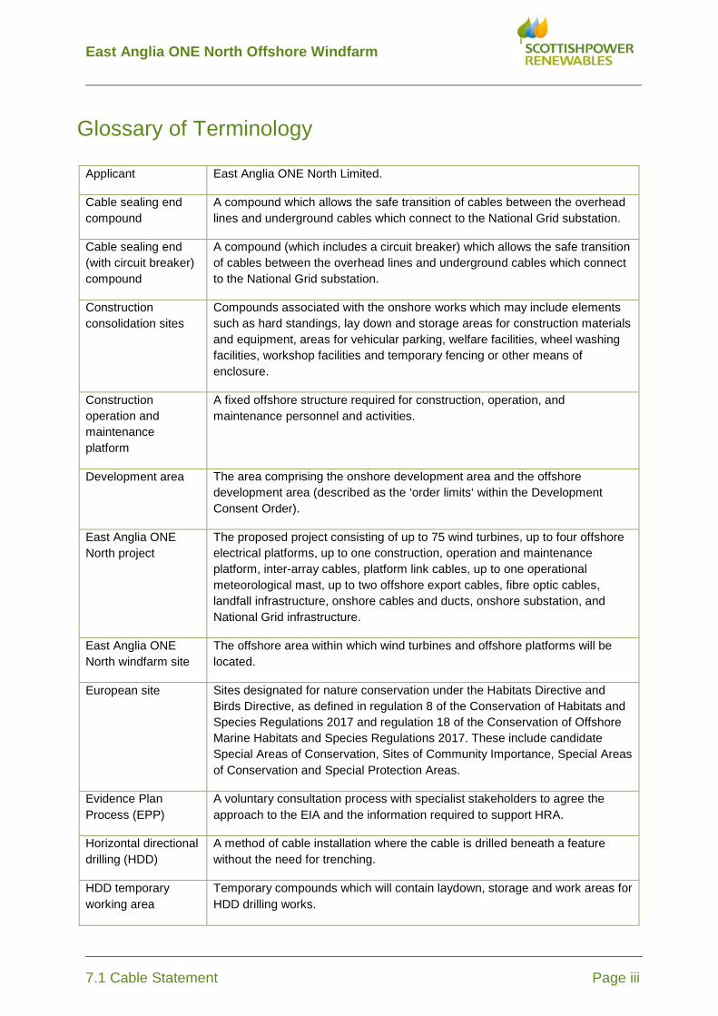
Glossary of Terminology
Applicant East Anglia ONE North Limited.
Cable sealing end compound
A compound which allows the safe transition of cables between the overhead lines and underground cables which connect to the National Grid substation.
Cable sealing end (with circuit breaker) compound
A compound (which includes a circuit breaker) which allows the safe transition of cables between the overhead lines and underground cables which connect to the National Grid substation.
Construction consolidation sites
Compounds associated with the onshore works which may include elements such as hard standings, lay down and storage areas for construction materials and equipment, areas for vehicular parking, welfare facilities, wheel washing facilities, workshop facilities and temporary fencing or other means of enclosure.
Construction operation and maintenance platform
A fixed offshore structure required for construction, operation, and maintenance personnel and activities.
Development area The area comprising the onshore development area and the offshore development area (described as the ‘order limits‘ within the Development Consent Order).
East Anglia ONE North project
The proposed project consisting of up to 75 wind turbines, up to four offshore electrical platforms, up to one construction, operation and maintenance platform, inter-array cables, platform link cables, up to one operational meteorological mast, up to two offshore export cables, fibre optic cables, landfall infrastructure, onshore cables and ducts, onshore substation, and National Grid infrastructure.
East Anglia ONE North windfarm site
The offshore area within which wind turbines and offshore platforms will be located.
European site Sites designated for nature conservation under the Habitats Directive and Birds Directive, as defined in regulation 8 of the Conservation of Habitats and Species Regulations 2017 and regulation 18 of the Conservation of Offshore Marine Habitats and Species Regulations 2017. These include candidate Special Areas of Conservation, Sites of Community Importance, Special Areas of Conservation and Special Protection Areas.
Evidence Plan Process (EPP)
A voluntary consultation process with specialist stakeholders to agree the approach to the EIA and the information required to support HRA.
Horizontal directional drilling (HDD)
A method of cable installation where the cable is drilled beneath a feature without the need for trenching.
HDD temporary working area
Temporary compounds which will contain laydown, storage and work areas for HDD drilling works.
East Anglia ONE North Offshore Windfarm
7.1 Cable Statement Page iv
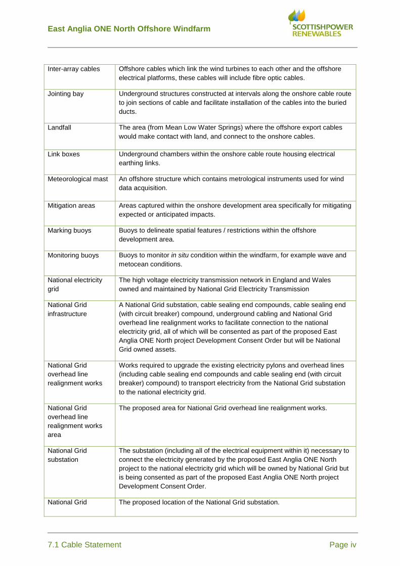
Inter-array cables Offshore cables which link the wind turbines to each other and the offshore electrical platforms, these cables will include fibre optic cables.
Jointing bay Underground structures constructed at intervals along the onshore cable route to join sections of cable and facilitate installation of the cables into the buried ducts.
Landfall The area (from Mean Low Water Springs) where the offshore export cables would make contact with land, and connect to the onshore cables.
Link boxes Underground chambers within the onshore cable route housing electrical earthing links.
Meteorological mast An offshore structure which contains metrological instruments used for wind data acquisition.
Mitigation areas Areas captured within the onshore development area specifically for mitigating expected or anticipated impacts.
Marking buoys Buoys to delineate spatial features / restrictions within the offshore development area.
Monitoring buoys Buoys to monitor in situ condition within the windfarm, for example wave and metocean conditions.
National electricity grid
The high voltage electricity transmission network in England and Wales owned and maintained by National Grid Electricity Transmission
National Grid infrastructure
A National Grid substation, cable sealing end compounds, cable sealing end (with circuit breaker) compound, underground cabling and National Grid overhead line realignment works to facilitate connection to the national electricity grid, all of which will be consented as part of the proposed East Anglia ONE North project Development Consent Order but will be National Grid owned assets.
National Grid overhead line realignment works
Works required to upgrade the existing electricity pylons and overhead lines (including cable sealing end compounds and cable sealing end (with circuit breaker) compound) to transport electricity from the National Grid substation to the national electricity grid.
National Grid overhead line realignment works area
The proposed area for National Grid overhead line realignment works.
National Grid substation
The substation (including all of the electrical equipment within it) necessary to connect the electricity generated by the proposed East Anglia ONE North project to the national electricity grid which will be owned by National Grid but is being consented as part of the proposed East Anglia ONE North project Development Consent Order.
National Grid The proposed location of the National Grid substation.

East Anglia ONE North Offshore Windfarm
7.1 Cable Statement Page v
substation location
Natura 2000 site A site forming part of the network of sites made up of Special Areas of Conservation and Special Protection Areas designated respectively under the Habitats Directive and Birds Directive.
Offshore cable corridor
This is the area which will contain the offshore export cables between offshore electrical platforms and landfall.
Offshore development area
The East Anglia ONE North windfarm site and offshore cable corridor (up to Mean High Water Springs).
Offshore electrical infrastructure
The transmission assets required to export generated electricity to shore. This includes inter-array cables from the wind turbines to the offshore electrical platforms, offshore electrical platforms, platform link cables and export cables from the offshore electrical platforms to the landfall.
Offshore electrical platform
A fixed structure located within the windfarm area, containing electrical equipment to aggregate the power from the wind turbines and convert it into a more suitable form for export to shore.
Offshore export cables
The cables which would bring electricity from the offshore electrical platforms to the landfall. These cables will include fibre optic cables.
Offshore infrastructure
All of the offshore infrastructure including wind turbines, platforms, and cables.
Offshore platform A collective term for the construction, operation and maintenance platform and the offshore electrical platforms.
Onshore cable corridor
The corridor within which the onshore cable route will be located.
Onshore cable route This is the construction swathe within the onshore cable corridor which would contain onshore cables as well as temporary ground required for construction which includes cable trenches, haul road and spoil storage areas.
Onshore cables The cables which would bring electricity from landfall to the onshore substation. The onshore cable is comprised of up to six power cables (which may be laid directly within a trench, or laid in cable ducts or protective covers), up to two fibre optic cables and up to two distributed temperature sensing cables.
Onshore development area
The area in which the landfall, onshore cable corridor, onshore substation, landscaping and ecological mitigation areas, temporary construction facilities (such as access roads and construction consolidation sites), and the National Grid Infrastructure will be located.
Onshore infrastructure
The combined name for all of the onshore infrastructure associated with the proposed East Anglia ONE North project from landfall to the connection to the national electricity grid.
Onshore preparation Activities to be undertaken prior to formal commencement of onshore

East Anglia ONE North Offshore Windfarm
7.1 Cable Statement Page vi
works construction such as pre–planting of landscaping works, archaeological investigations, environmental and engineering surveys, diversion and laying of services, and highway alterations.
Onshore substation The East Anglia ONE North substation and all of the electrical equipment within the onshore subsation and connecting to the National Grid infrastructure.
Onshore substation location
The proposed location of the onshore substation for the proposed East Anglia ONE North project.
Platform link cable Electrical cable which links one or more offshore platforms. These cables will include fibre optic cables.
Safety zones A marine area declared for the purposes of safety around a renewable energy installation or works / construction area under the Energy Act 2004.
Scour protection Protective materials to avoid sediment being eroded away from the base of the foundations as a result of the flow of water.
Transition bay Underground structures at the landfall that house the joints between the offshore export cables and the onshore cables.

East Anglia ONE North Offshore Windfarm
7.1 Cable Statement Page vii
Table of Contents Cable Statement 1 1 Summary 1 2 Introduction 2 3 Description of electrical infrastructure 3 4 Consenting of the electrical infrastructure 6 5 Description of generating equipment 7 6 Offshore cable installation 8 7 Onshore cable installation 11 8 East Anglia ONE North onshore substation 13 9 National Grid substation 14 10 National Grid overhead line realignment works construction 15 11 Status of grid connection 17

East Anglia ONE North Offshore Windfarm
7.1 Cable Statement Page 1
Cable Statement 1 Summary 1. East Anglia ONE North Limited (the “Applicant”) is planning to develop the
East Anglia ONE North Offshore Windfarm (the “Project”) an offshore generating station, located approximately 36km from the port of Lowestoft and 42km from Southwold and covering an area of approximately 208km2, together with associated development to connect the generating station to the national electricity grid.
2. The Project will, amongst other things, comprise of up to 67 wind turbines, up to four offshore electrical platforms, up to one offshore construction, operation and maintenance platform and up to one offshore meteorological mast.
3. The Applicant is submitting an application to the Secretary of State under Section 37 of the Planning Act 2008 for a Development Consent Order (“DCO”) for the construction, operation, maintenance and decommissioning of the Project (the “Application”).
4. This Cable Statement has been prepared in accordance with Regulation 6(1)(b)(i) of the Infrastructure Planning (Applications: Prescribed Forms and Procedures) Regulations 2009 (the “APFP Regulations”) which requires the applicant for a DCO for the construction of an offshore generating station to provide a statement regarding the route and method of installation of any cable connecting the generating station to the onshore national electricity grid.
5. The Applicant's application contains all of the offshore electrical infrastructure and onshore infrastructure required for the Project, summarised as follows:
• The offshore electrical infrastructure consisting of inter-array cables, up to four offshore electrical platforms, up to one construction, operation and maintenance platform, platform link cables and export cables from the offshore electrical platforms to the landfall.
• The onshore electrical infrastructure consisting of works at landfall to connect the offshore export cables with the onshore cables, up to six onshore electrical cables to bring electricity from landfall to a new onshore substation, and National Grid infrastructure (including a National Grid substation, up to three cable sealing end compounds, and National Grid overhead line realignment works) to connect the Project to the national electricity grid.
6. The Grid Connection Agreement that has been secured for the East Anglia ONE North project is for a connection located in or around Leiston.
East Anglia ONE North Offshore Windfarm
7.1 Cable Statement Page 2
2 Introduction 7. This Cable Statement has been prepared by the Applicant pursuant to
Regulation 6(1)(b)(i) of the APFP Regulations.
8. This Statement forms part of the application to the Secretary of State for the Project for a DCO to construct and operate an offshore generating station with up to 67 turbines. As the total installed capacity of the Project will exceed 100 MW it is a Nationally Significant Infrastructure Project (“NSIP”) as defined under sections 14(1)(a) and 15(3) of the Planning Act 2008.
9. The East Anglia ONE North offshore windfarm site is located approximately 36km from the port of Lowestoft and 42km from Southwold and covering an area of approximately 208km2. Offshore export cables will bring electricity from offshore electrical platforms to landfall located north of Thorpeness in Suffolk. Onshore electrical cables will bring electricity from landfall to a new onshore substation in the vicinity of Grove Wood, Friston and will then connect into new National Grid infrastructure to include a new National Grid substation, cable sealing end compounds and National Grid overhead line realignment works with up to one additional overhead line pylon.
10. Under sections 14(1)(b) and 16 of the Planning Act 2008, the installation of an electric line above ground in England is an NSIP unless it falls within certain exclusions. It is not anticipated that any the exemptions will apply to the overhead line realignment works and so the overhead line realignment works are considered to be an NSIP and have been treated as such.
11. A detailed description of the Project is provided in the Environmental Statement (Document reference 6.1) and in particular in Chapter 6 Project Description (Document reference 6.1.6).
12. This Statement provides details of the proposed offshore and onshore cable routes and cable installation methods and is intended to provide a summary of the detailed information set out in the Project Description of the Environmental Statement.

East Anglia ONE North Offshore Windfarm
7.1 Cable Statement Page 3
3 Description of electrical infrastructure 13. The Application contains all of the electrical cable works required for the
Project.
Electrical solution
14. The project will use a High Voltage Alternating Current (HVAC) electrical system.
Offshore electrical infrastructure
15. Inter-array cables will collect and transfer power generated by the wind turbines to the offshore electrical platforms. The cables connect the wind turbines together into strings, with the number of wind turbines connected together depending on factors such as the generation capacity of each wind turbine on the relevant cable network, distance between wind turbines and the cable sizes available. The strings of wind turbines would then in turn be connected to the offshore electrical platforms.
16. Up to four offshore electrical platforms would collect electricity from the wind turbines and transport it to shore via up to two export cables. Platform link cables would connect the offshore platforms to one another.
17. The two export cables would connect to the onshore infrastructure at landfall located north of Thorpeness in Suffolk. Each export cable would have a maximum length of 76km.
Landfall
18. The offshore export cables would make landfall north of Thorpeness.
19. Horizontal Directional Drilling (“HDD”) would be used to install the ducts required to accommodate up to two export cables and up to two fibre optic cables associated with the Project.
20. At the landfall the cable ducts would be installed with a minimum setback distance of 85m from the cliff top to ensure the integrity of the cliff is not compromised and to allow for natural coastal erosion. The HDD and cable ducts would extend under the cliffs, beach and intertidal area without interacting with these features. The offshore export cables and fibre optic cables will be installed within the cable ducts soon after cable duct installation or at a later date.
21. Up to two transition bays would be installed at the landfall with a minimum setback distance of 85m from the cliff top. Each transition bay would comprise a buried concrete-lined structure. The purpose of the transition bay at the
East Anglia ONE North Offshore Windfarm
7.1 Cable Statement Page 4
landfall would be to provide housing for the joint between the heavily armoured offshore export cables and the onshore cables.
Onshore cables
22. The proposed route for the onshore cables is approximately 9km long.
23. There would be up to six onshore electrical cables, up to two fibre optic cables and up to two distributed temperature sensing (DTS) cables laid in a total of two trenches. Cables will typically be installed approximately 1.2m below ground level, to transport the electrical power from the landfall to the onshore substation. Cables may be placed directly underground without ducting, although ducting may be used in some or all of the route. Buried jointing bays will be required along the onshore cable route to join each section of the cable together
Onshore substation and National Grid substation
24. Two onshore substations are required for the East Anglia ONE North project: one is the proposed East Anglia ONE North onshore substation (the “onshore substation”) and the other is the National Grid onshore substation (the “National Grid substation”). It is proposed that they will be co-located in order keep development contained within a localised area and, in doing so, contain the extent of potential impacts.
25. The onshore substation and National Grid substation would contain electrical equipment such as power transformers, gantries, switchgear, reactive compensation equipment, electrical protection equipment, harmonic filters, cables and backup generators and would also include lightning protection masts, control buildings, communications masts, access, fencing and other associated equipment, structures or buildings.
26. The purpose of the onshore substation is to convert the electricity delivered via the onshore cables to the correct voltage and quality for the National Grid substation to connect into the electrical transmission network (overhead lines).
27. The onshore substation would be connected to the National Grid substation by means of up to six electrical cables, up to two fibre optic cables and up to two DTS cables.
28. The National Grid substation will either be an ‘air insulated switchgear’ (AIS) substation or a ‘gas insulated switchgear’ (GIS) substation depending on the switchgear technology employed.
National Grid overhead line realignment works
29. Up to three cable sealing end compounds (one of which may include circuit breakers) are required to connect the National Grid substation to three of the

East Anglia ONE North Offshore Windfarm
7.1 Cable Statement Page 5
overhead line circuits. Each cable sealing end compound is connected to the National Grid substation by underground high voltage and low voltage electrical and communications cables. A fourth overhead line circuit will connect directly to the National Grid substation.
30. The National Grid substation will connect into the National Grid 400kV overhead lines that connect Sizewell and Bramford. To facilitate these connections, modifications to the existing overhead lines will be required which will include the permanent realignment of a short section of the northern and southern overhead lines. This permanent realignment will create the necessary separation distance between the two overhead lines to enable the construction of the new cable sealing end compounds to facilitate connection into the new National Grid substation. These works will require the reconstruction and/or relocation of up to two pylons and construction of up to one additional pylon in order to realign the northern overhead lines and the reconstruction and/or relocation of up to one pylon in order to realign the southern overhead lines. A temporary diversion of the northern and southern overhead lines will be required to facilitate the overhead line realignment. The temporary diversion of the northern overhead line will use up to two temporary guyed masts or up to two temporary pylons to support the circuits during the period of realignment. The temporary diversion of the southern overhead line will use either an existing pylon or up to two temporary guyed masts or up to two temporary pylons to support the circuits during the period of realignment.
East Anglia ONE North Offshore Windfarm
7.1 Cable Statement Page 6
4 Consenting of the electrical infrastructure 31. Part 1 of Schedule 1 of the draft DCO describes the works for which
development consent is being sought.
Offshore electrical infrastructure
32. The inter-array cables and up to one meteorological mast form part of the generating station NSIP set out within Work No. 1.
33. Up to one construction, operation and maintenance platform comprises Work No. 2, up to four offshore electrical platforms comprise Work No. 3 and the cable connections between the offshore platforms comprise Work No. 4. The export cables comprise Work No. 5. These works are considered to be "associated development" to the generating station NSIP within Section 115 of the Planning Act 2008, in that they are not an aim in themselves but are required to export the electricity generated by the turbines.
Landfall and onshore electrical infrastructure
34. The Applicant has included the landfall, onshore cables and the East Anglia ONE North onshore substation as "associated development" within its DCO application to the Secretary of State.
35. The landfall is comprised within Work Nos. 6 and 8 and includes the offshore export cables at the landfall, up to two transition bays and the onshore cables (comprising up to six electrical cables, up to two fibre optic cables and up to two DTS cables).
36. The onshore cables are comprised within Work Nos. 9, 11 to 13, 16 to 23, 26 and 31.
37. Work No. 30 is the East Anglia ONE North onshore substation and Work No. 32 comprises the cables connecting the East Anglia ONE North onshore substation to the National Grid substation.
38. The National Grid overhead line realignment works including up to one new additional pylon are considered to be a separate NSIP within the DCO and are comprised within Work Nos. 39 and 40. Work No. 38 is the cable sealing end compounds comprising compounds with electrical equipment and overhead line gantries and is also considered to form part of the overhead lines NSIP.
39. The National Grid substation comprised within Work No. 41 is considered to be “associated development” to the overhead lines NSIP.
East Anglia ONE North Offshore Windfarm
7.1 Cable Statement Page 7
5 Description of generating equipment 40. The wind turbine consists of three primary components (i.e. the tower, the
nacelle and the rotor). The rotor is the device which, through circular motion, extracts the energy from the wind. The nacelle houses the equipment that can turn rotational motion into electrical energy. The tower supports the nacelle and gives the rotor the necessary height.
41. The capacity of the Project will depend on the number of wind turbines that are installed and their individual rating. The Project would consist of up to a maximum of 67 wind turbines with a rotor diameter range of up to 250 metres.
42. In the UK, offshore windfarm developers such as the Applicant can either construct the offshore transmission assets themselves or opt for an Offshore Transmission Owner (“OFTO”) to do so. Offshore transmission assets generally consist of the onshore infrastructure required to connect to the national electricity transmission system, the offshore export cables and offshore electrical stations. If the Applicant constructs the assets itself, then it must transfer the assets to an OFTO. OFTOs are selected on a competitive basis through a tender process managed by the Office of Gas and Electricity Markets (“Ofgem”). It is anticipated that the Applicant will opt for the generator build option which means that the offshore transmission assets will be transferred to an OFTO post-construction.

East Anglia ONE North Offshore Windfarm
7.1 Cable Statement Page 8
6 Offshore cable installation Cable installation methods Inter-array cables
43. The inter-array cables will be buried, where it is feasible to do so. Optimum burial depth may not be achieved in areas of rock outcrop or where there is a high frequency of boulders. Where optimum burial depth is not achieved the cable may be protected to prevent movement of the cables, to prevent any risk to other marine users and to protect the cables from impacts arising from other marine activities such as fishing.
44. The inter-array cables are expected to be installed from a cable laying vessel, which will be equipped with specialist cable handling equipment and will have support vessels in attendance as necessary, for example anchor handling. The cables are loaded on to cable carousels or cable drums, mounted on the deck of the vessel.
45. There are several different methods available for the installation of offshore cables, including the following:
• Ploughing
A forward blade cuts through the sea bed laying the cable behind. Ploughing tools could be pulled directly by a surface vessel or could be mounted onto self-propelled caterpillar tracked vehicles which run along the sea bed taking power from a surface vessel. The plough inserts the cable as it passes through the ground.
• Trenching or cutting
Trenching or cutting would be used where other methods for burying the cable are not economically and / or technically feasible.
This method generally consists of three operations. First a trench is excavated or cut while placing the sediment and fill next to the trench. The cable is subsequently laid in the trench and lastly the sediment or fill is returned to the trench.
• Jetting
This method involves the use of a positioned cable vessel and a hydraulically powered water jetting device that simultaneously lays and embeds the cables in one continuous trench. The equipment uses pressurised water from a water pump system on board the cable vessel to fluidize sediment.
East Anglia ONE North Offshore Windfarm
7.1 Cable Statement Page 9
46. There are two methods of water jetting which are:
• Laying the cable first and jetting at a later time - The cable is laid on the sea bed first and afterwards a jetting sledge is positioned above the cable. Jets on the sledge flush water beneath the cable fluidising the sand whereby the cable, by its own weight, sinks to the depth set by the operator. As the sediment is fluidised a minor amount of sediment spill is expected.
• Laying the cable and jetting at the same time - In this method water jets are used to jet out a trench and the cable is laid into the trench behind the jetting lance. As with the previous method, as the sediment is fluidised a minor amount of sediment spill is expected.
47. Jetting tools can be pulled directly by a surface vessel or can be mounted onto self-propelled caterpillar tracked vehicles which run along the sea bed taking its power from a surface vessel.
48. The extent to which these cable burial techniques will be used will be dependent upon the results of detailed pre-construction seabed surveys of the final cable route and the associated cable burial assessment process.
Export cables
49. The same techniques described for array cable installation will be used to install the offshore export cables. In addition vertical injector burial method may be used in shallow waters. This is a large jetting and cutting tool which is strapped to the side of a barge and the cable is laid in the foot of the trench. This technique can provide deeper than traditional method burial which can be utilised through areas of high sea bed mobility or whilst crossing areas of high risk.
50. Export cables between the offshore electrical platforms and landfall may require a number of connections or joints along their length. Jointing of the offshore export cable will be undertaken at sea. Due to the complexity of offshore jointing, the number of joints will be kept to a minimum.
Cable protection
51. In some cases the above installation techniques cannot be applied and it is necessary to use alternative methods for installing the cable when it cannot be buried. Details of some of the techniques employed are given below:
• Concrete mattresses

East Anglia ONE North Offshore Windfarm
7.1 Cable Statement Page 10
These are prefabricated flexible concrete coverings that are laid on top of the cable. Grout or sand filled bags could be used as an alternative to concrete mattresses for smaller scale activities.
• Rock Placement
Rock placement involves the laying of a rock layer on top of the cable to provide protection which is effective on crossings or areas where unsuitable sea bed conditions are encountered. This can be used where long sections of cable require protection.
• Frond mattresses
Frond mattresses could be used to provide protection by stimulating the settlement of sediment over the cable. This method develops a sand wave over time protecting the cable but is only suitable in certain water conditions. This method may be used near offshore structures although experience has shown that storms can strip deposited materials from the frond.
• Uraduct
Uraduct is effectively a protective shell which comes in two halves and is fixed around the cable to provide mechanical protection. Uraduct is generally used for short spans at crossings or near offshore structures where there is a high risk from falling objects. Uraduct does not provide protection from damage due to fishing trawls or anchor drags.
East Anglia ONE North Offshore Windfarm
7.1 Cable Statement Page 11
7 Onshore cable installation Cable landfall
52. HDD would be used to install the ducts required to accommodate up to two export cables and up to two fibre optic cables associated with the Project.
53. HDD involves a three-stage process wherein:
• The first stage drills a small diameter pilot bore along the designated route;
• The second stage enlarges the bore by passing a larger cutting tool known as the reamer through the bore a number of times to progressively enlarge the bore to the requirement diameter; and
• The third stage places the duct in the enlarged hole (the offshore export cable and / or fibre optic cables will then be pulled through this duct once the duct is installed or at a later stage in the works).
Transition bays
54. Each transition bay would comprise a buried concrete-lined structure. The purpose of the transition bay at the landfall would be to contain the joint between the offshore cables and the onshore cables.
Onshore cables
55. The onshore cable corridor between the transition bays and the onshore substation would be approximately 9km in length.
56. There would be up to six onshore cables and two fibre optic cables, laid in two trenches (three onshore cables and one fibre optic cable in each trench). Cables will be installed approximately 1.2m below ground level, to transport the electrical power from the landfall to the onshore substation location. Cables may be placed directly underground without ducting, although ducting may be used in some or all of the route. Cables would typically be up to 170mm in diameter (the ducts being larger).
57. Each cable trench will also require a DTS cable to be installed next to the ducts or cables. Typically, this system comprises of a fibre optic cable within a protective sheath or duct. The DTS identifies faults in the buried cables during operation, allowing a more precise location of any fault to be identified and more accurate excavation of the ground to facilitate the cable repair.
58. Onshore cabling is typically provided on drums of 1,000m in length. Buried jointing bays will be required along the onshore cable route to join each section of the cable together.

East Anglia ONE North Offshore Windfarm
7.1 Cable Statement Page 12
59. These buried jointing bays (which will be approximately 15m long x 3m wide x 1.7m deep) will be constructed at intervals along the onshore cable route (to allow cable pulling and jointing at a later stage). The precise location of the jointing bays will be determined during detailed design.
60. Underground cable installation is well-established and aside from the engineering challenges it incorporates environmental management and mitigation measures as standard practice.
61. The onshore cables for the Project would be installed in two parallel trenches with cement bound sand and originally excavated backfill, where suitable.
62. Concrete cable protection tiles (or similar) would be fitted above the cables in each trench, featuring indented lettering warning of the danger of electricity below. Between the protection tiles and the ground surface would be plastic warning tape containing text alerting future excavators to the danger of the cables below.
63. Construction activities would be undertaken within the onshore cable route, which would generally be no wider than 32m. The onshore cable route will be fenced along some or all of its length.
East Anglia ONE North Offshore Windfarm
7.1 Cable Statement Page 13
8 East Anglia ONE North onshore substation 64. The purpose of the onshore substation is to convert the electricity delivered
via the onshore cables to the correct voltage and quality for the National Grid substation to connect into the electrical transmission network (overhead lines).
65. The onshore substation would be located within a single compound. In addition to the main GIS building, the substation compound would contain electrical equipment including power transformers, switchgear, reactive compensation equipment, harmonic filters, cables, lightning protection masts, control buildings, communications masts, backup generators, access, fencing and other associated equipment, structures or buildings. The onshore substation will have an optimised layout.
66. Construction will include a number of key stages, including earthworks, foundations, superstructure and equipment installation.
67. The onshore substation would be connected to the National Grid substation by means of up to six electrical cables, up to two fibre optic cables and up to two DTS cables. These may be installed directly underground or within concrete troughs.

East Anglia ONE North Offshore Windfarm
7.1 Cable Statement Page 14
9 National Grid substation 68. The National Grid substation will either be an AIS or a GIS substation
depending on the switchgear technology employed.
69. Within an AIS substation, equipment is designed to be left open to the elements and cooled by ambient air temperature. Within a GIS substation, equipment is designed to be insulated and cooled by a pressurised gas (e.g. sulphur hexafluoride (SF6)).
70. Construction will include a number of key stages, including earthworks, foundations, superstructure and equipment installation.
East Anglia ONE North Offshore Windfarm
7.1 Cable Statement Page 15
10 National Grid overhead line realignment works construction 71. The National Grid substation will connect into each of the four circuits on the
National Grid 400kV overhead lines. To facilitate these connections, modifications to the existing overhead lines will be required which will include the permanent realignment of a short section of the northern overhead line further north and potentially a slight permanent realignment of the southern overhead line. This permanent realignment will create the necessary separation distance between the two overhead lines to enable the construction of new cable sealing end compounds to facilitate connection into the new National Grid substation.
72. The northern realignment works will require the temporary diversion of the northern overhead line with up to two temporary guyed masts or up to two temporary pylons to support the circuits during the period of temporary diversion. Once the temporary diversion is in place, the permanent realignment of the northern overhead lines will be undertaken which will require the reconstruction and/or relocation of up to two pylons and construction of up to one additional pylon.
73. The works on the southern overhead lines will require the temporary diversion of one or both circuits on the southern overhead line using either an existing pylon, or up to two temporary guyed masts or up to two temporary pylons to support the circuits during the period of temporary diversion. Once the temporary diversion is in place, works on the southern overhead lines will be undertaken which will require the reconstruction and/or relocation of up to one pylon.
74. It may also be necessary to strengthen or modify other existing pylons within the overhead line realignment works area although the locations of these pylons will not change.
75. Up to three cable sealing end compounds are required to connect the National Grid substation to each of the overhead line circuits, one of which will include a circuit breaker, disconnectors and current/voltage transformers for protection purposes (i.e. to ensure safe operation and isolation/earthing of the circuit during periods of maintenance and to isolate relevant sections of the circuit during operation).
76. Each cable sealing end compound will be connected to the National Grid substation by underground high voltage and low voltage electrical and communications cables. A fourth overhead line circuit will connect directly to the National Grid substation.

East Anglia ONE North Offshore Windfarm
7.1 Cable Statement Page 16
77. The temporary diversions of the northern and southern overhead lines will be removed when the respective permanent overhead line realignment is complete and brought into service.
78. The extent of the National Grid overhead line realignment works will be the same irrespective of whether AIS or GIS substation technology is utilised.

East Anglia ONE North Offshore Windfarm
7.1 Cable Statement Page 17
11 Status of grid connection 79. On 21 December 2017, ScottishPower Renewables (UK) Limited (the parent
company of East Anglia ONE North Limited) and National Grid Electricity Transmission plc entered into an agreement to vary a Bilateral Connection Agreement and Construction Agreement for the East Anglia ONE North Project.
80. This agreement provides for the connection for the East Anglia ONE North project at a new 400kV substation in or around Leiston. This new 400kV substation is to be located at Grove Wood, near Friston.