eastman blue streak ii brute model 627x - amazon...
TRANSCRIPT
779 Washington St., Buffalo, N.Y. 14203-1396 U.S.A. • (716) 856-2200 • Fax (716) 856-1140 or (716) 856-2068Manufactures of Eastman Cloth Cutting and Cloth Spreading Machines
Website: www.EastmanCuts.com
EASTMAN ®
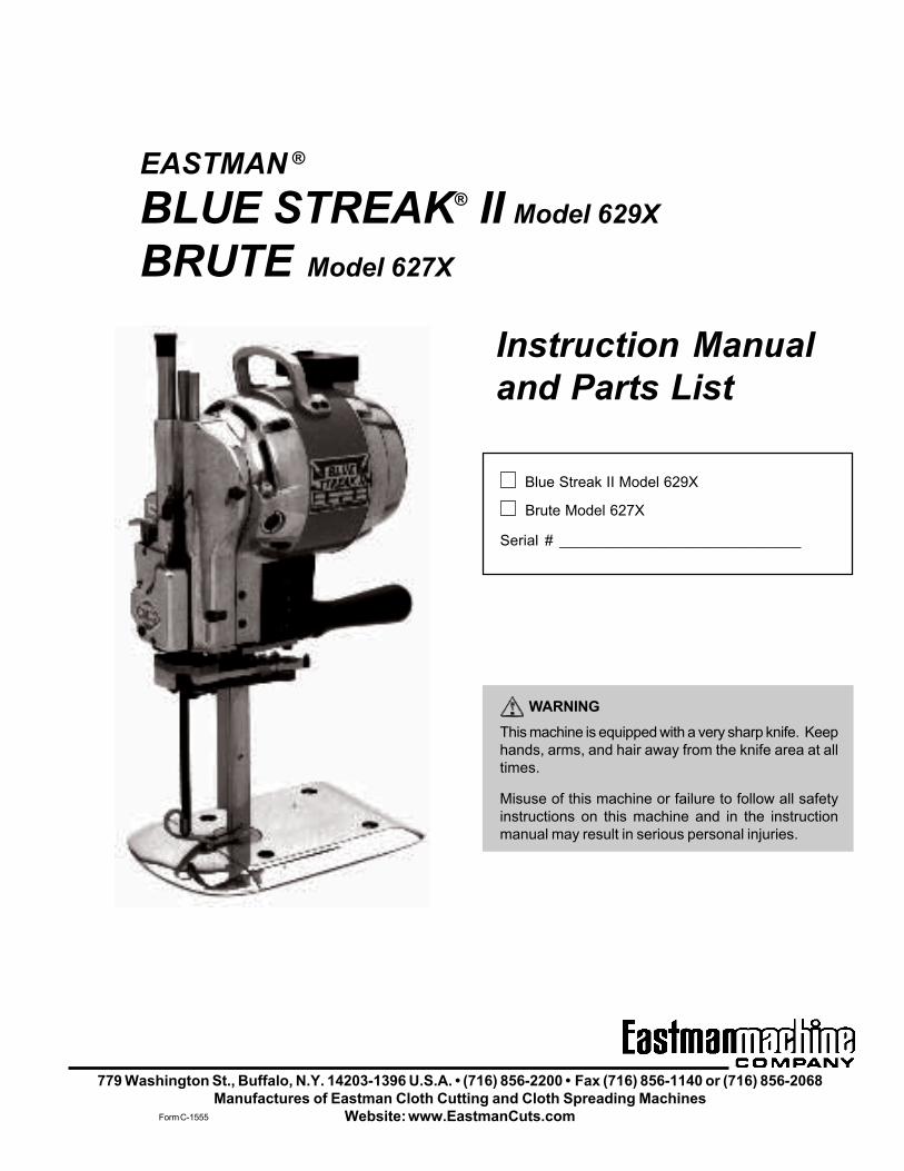
BLUE STREAK® II Model 629X
BRUTE Model 627X
Instruction Manualand Parts List
Blue Streak II Model 629X
Brute Model 627X
Serial # _____________________________
WARNINGThis machine is equipped with a very sharp knife. Keephands, arms, and hair away from the knife area at alltimes.
Misuse of this machine or failure to follow all safetyinstructions on this machine and in the instructionmanual may result in serious personal injuries.
Form C-1555
EASTMAN
Limited Warranty. Eastman warrants to the buyer that the Blue Streak II and Brute shall be free fromdefects in materials or workmanship for a period of 180 days commencing on the date of invoice. Anygoods or parts claimed by the buyer to be defective must be returned to Eastman, freight charges prepaid,within the 180–day warranty period. If Eastman determines that the goods or parts are defective in mate-rials or workmanship, Eastman's sole obligation under this warranty shall be, at Eastman's sole option, torepair or replace the defective goods or parts or to provide to the buyer a credit equal to the portion of thepurchase price allocable to the defective goods or parts. This warranty shall not apply if defects arecaused by product misuse or neglect, if the machine has been altered or modified by the buyer, or if otherthan genuine Eastman belts, emery wheels, knives or parts are used in the machine. THIS WARRANTYIS THE ONLY WARRANTY APPLICABLE TO THIS PURCHASE. SELLER DISCLAIMS ALL OTHERWARRANTIES, EXPRESS OR IMPLIED, INCLUDING, BUT NOT LIMITED TO, THE IMPLIED WARRAN-TIES OF MERCHANTABILITY AND FITNESS FOR A PARTICULAR PURPOSE.
Limitation of Liability. Eastman's liability to the buyer, and the buyer's remedies from Eastman, whetherin contract, negligence, tort, under any warranty or otherwise, shall be limited to the remedies provided inthe foregoing Limited Warranty. In no event shall Eastman have any responsibility or liability to the buyerfor (a) any special, indirect, incidental, or consequential damages, including, but not limited to, loss of use,revenue, or profit, even if Eastman has been advised of the possibility of such damages, or (b) any claimagainst the buyer by any third party. The price stated for the product sold is a consideration for limitingEastman's liability.
Form C-1555

iForm C-1555
Patents StatementSome parts of this manual and the equipment it describesare protected by the following U.S. patents: 5,178,232,4,609,244, 5,111,582, 4,761,878, and D281,416. Otherpatents pending.
Trademarks StatementThe names Eastman, Uni-Safe, Blue Streak, and BevelBloc are registered trademarks of the Eastman MachineCompany.
This manual contains instructions and part numbers fortwo different machines: Brute Model 627 and Blue Streak IIModel 629. If you contact Eastman Machine Company forinformation or to order parts, always specify the machinename and model number.
If you are ordering electrical components, specify the volt-age, frequency (Hz), and speed (RPM) of your machine.You can find this information on a label attached to yourmachine.
IMPORTANT
Table of ContentsSafety Information ........................................ 1
General Safety Precautions ...................................... 1
Initial Set Up ............................................................. 2
Operation ...................................................... 2
Operating Procedure ................................................ 3Safety Considerations ................................................. 3Starting the Machine................................................... 4Making a Cut .............................................................. 4Turning Off the Machine .............................................. 4
Routine Maintenance ................................... 4
Care of the Machine .................................................. 4Daily ........................................................................... 4Twice Weekly .............................................................. 5Weekly ....................................................................... 5
Lubrication ................................................................ 5Daily ........................................................................... 5Weekly ....................................................................... 5Monthly ....................................................................... 5
Sharpening the Knife ................................................ 5Removing the Sharpener ............................................. 5
Replacing the Rubber Driver Pulley......................... 6
Adjusting the Belt Sharpener ................................... 7Changing Sharpener Belts .......................................... 7Adjusting Stabilizers for Central Alignment ................. 7Checking the Sharpener Shoes ................................... 8
Checking the Extreme Down Position of the Sharpener 8Checking the Stop Screw on the Sharpener Shoe ....... 9Check the Width of the Bevel on the Knife .................. 9Changing the Knife ..................................................... 9
Adjusting Bevel Bloc® Shoes ................................ 11
Adjusting Bevel Bloc® Shoes (continued) ............ 12
Troubleshooting ...................................................... 14
Freeing Frozen Guides ........................................... 16
Accessories ................................................ 16
Stainless Steel Mesh Gloves .................................. 16Ordering Details ........................................................ 17
Genuine Eastman Abrasive Belts........................... 17
Ergo-Handle ............................................................ 18
Specialty Machines ................................................. 18Plastic Master Model 627PM/629PM ........................ 18Micro Fog Model 627MF/629MF ............................... 19
Illustrated Parts List ................................... 20Motor Assemblies ..................................................... 20Front Bearing Housing Assembly .............................. 20Sharpener Housing Assembly ................................... 20Lower Gear Bracket Assembly.................................. 20Standard and Baseplate Assembly ........................... 20
Electrical Connections ............................... 36
ii
EASTMAN
Form C-1555
List of Figures
Figure 22. Single/Dual-Phase Motor Assembly(Exploded View) ......................................... 23
Figure 23. Three-Phase Motor Assembly(Assembled View) ...................................... 24
Figure 24. Three-Phase Motor Assembly(Exploded View) ......................................... 25
Figure 25. Front Bearing Housing with OilerAssembly (Exploded View) ......................... 27
Figure 26. Sharpener Housing Assembly(Assembled, Front View) ............................ 28
Figure 27. Sharpener Housing Assembly(Exploded, Front View) ............................... 29
Figure 28. Sharpener Housing Assembly(Assembled, Rear View) ............................. 30
Figure 29. Sharpener Housing Assembly(Exploded, Rear View) ................................ 31
Figure 30. Lower Gear Bracket Assembly(Assembled View) ...................................... 32
Figure 31. Lower Gear Bracket Assembly(Exploded View) ......................................... 33
Figure 32. Standard and Baseplate Assembly(Assembled View) ...................................... 34
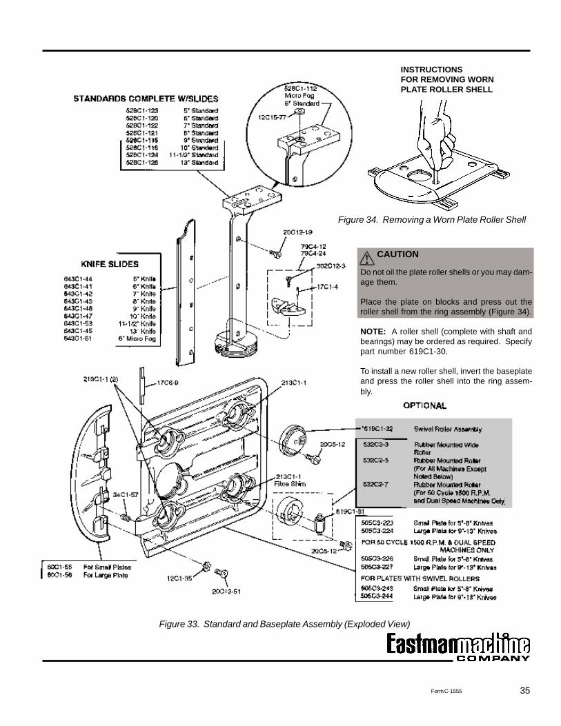
Figure 33. Standard and Baseplate Assembly(Exploded View) ......................................... 35
Figure 34. Removing a Worn Plate Roller Shell ........... 35
Figure 1. Operating Features ....................................... 2Figure 2. Controls and Adjustments ............................ 3Figure 3. Removing the Sharpener ............................... 6Figure 4. Replacing the Rubber Driver Pulley ............... 6Figure 5. Changing the Sharpener Belts ...................... 7Figure 6. Adjusting the Stabilizers ............................... 7Figure 7. Changing the Knife ....................................... 9Figure 8. Available Eastman Knife Types ................... 10Figure 9. Adjusting Bevel Bloc Shoes......................... 11Figure 10. Bevel Bloc Shoe Assembly ........................ 12Figure 11. Maintenance Supplies ................................ 13Figure 12. Single-Phase Electrical Configuration ......... 15Figure 13. Freeing Frozen Guides ............................... 16Figure 14. Available Metal Mesh Glove Styles ............. 17Figure 15. Eastman Abrasive Belts ............................. 17Figure 16. Edges Produced by Different Belt Grits ...... 18Figure 17. Ergo-Handle ............................................... 18Figure 18. Plastic Master ............................................ 19Figure 19. Micro Fog ................................................... 19Figure 20. Standard and Baseplate Assembly
(Exploded View) ......................................... 21Figure 21. Single-Phase Motor Assembly
(Assembled View) ...................................... 22
1Form C-1555
Throughout this manual, safety information is presented byuse of the terms Warning, Caution, and Note. These termshave the following meanings:
WARNING
A warning contains critical information regarding poten-tial safety hazards that can occur during proper use ormisuse of the machine. Failure to follow these proce-dures may result in serious personal injury to the user.
CAUTION
A caution contains instructions for the use or mainte-nance of the machine. Failure to follow these proceduresmay result in damage to the machine.
Safety and IndemnificationDuring the life of the machine, the purchaser agrees to pro-vide to all machine users (including its own employees andindependent contractors) all relevant safety information, in-cluding warning labels and instruction manuals. The pur-chaser also agrees to maintain the safety features and work-ing condition of the machine, and to adequately train allusers in the safe use and maintenance of the machine. Thepurchaser agrees to defend, protect, indemnify, and holdEastman Machine Company harmless from and against allclaims, losses, expenses, damages, and liabilities to theextent that they have been caused by the purchaser’s fail-ure to comply with the terms and instructions of this manual.
Safety Information
• The purchaser must provide appropriate safety mea-sures and equipment as recommended in this manual.Observe all statutory requirements concerning the useof hazardous machinery that apply to your location.
• Do not modify this machine or disable safety fea-tures. Unauthorized modification may result in seri-ous personal injuries to the user. Electrical connec-tions to this machine must be made by a qualifiedelectrician familiar with applicable codes and regula-tions. To prevent electrocution, a ground lead mustbe connected to terminal “E” on the attachment plug.
• This machine is intended ONLY for hand-held opera-tion. Misuse of this machine or use of this machineas part of another machine may result in serious per-sonal injuries to the user.
• Safety labels must be kept clean and legible at alltimes. Call the Eastman Machine factory to orderreplacement labels.
WARNING
• This machine is equipped with a very sharp and dan-gerous knife. Keep hands, arms, and hair away fromthe knife area at all times. When the machine is notin use, keep the pressure foot knife guard loweredand locked at all times. Safety gloves and glassesand appropriate clothing may prevent serious personalinjuries.
• Disconnect the power supply from the machine whenit is not in use or during routine maintenance, includ-ing lubrication.
• The purchaser must instruct all operators in the properuse of the machine according to the instructions onthe machine and in this manual. This training mustinclude instruction on the potential safety hazards aris-ing from the use or misuse of the machine. In addi-tion to such training, the purchaser should providewritten work instructions as necessary to ensure cor-rect use of the machine for specific cutting applica-tions.
General Safety Precautions
2
EASTMAN
Form C-1555
Operation
Before operating the machine, read these instructions care-fully. Familiarize yourself with all the functions and adjust-ments of the machine.
CAUTION
Operating this machine from an incorrect electricalsupply may damage it.
2. Check that the machine has been lubricated accordingto the schedule listed in Routine Maintenance–Lubrica-tion on page 5.
Note: At this time, carry out the full monthly lubricationschedule on page 5.
3. Make sure that the sharpener is in the locked position.To do this, push in the turning knob (Figure 2, F). Whiledepressing the turning knob, turn the machine over a fewrevolutions by hand to see if the knife reciprocateseasily. If the knife does not move easily, the sharpenermay be in the unlocked position.
4. To lock the sharpener in place, lift the release lever(Figure 2, D) and press the sharpener lever (Figure 2, E)to release the sharpener. Raise the sharpener bracket(Figure 2, S) by hand to lock it in place. Once thesharpener is locked in place, you may disengage therelease lever and sharpener lever. Repeat step 3 toensure that the sharpener is now locked. If not, repeatthis step.
5. Visually inspect the blade to ensure that the top of theknife is flush with the knife lockbolt (Figure 7, 1 on page9) and that the knife is perpendicular to the baseplate. Ifyou need to adjust the alignment of the blade, seesection Changing the Knife on page 9.
6. Check that the motor switch is in the OFF position. Thenconnect the attachment plug to the terminal block on themachine.
7. Hold the operating handle and turn on the machine.Allow the blade to reach full speed. If the blade isstruggling, the sharpener is still not in the lockedposition. If this is the case, turn off the machine and dothe following:
7.1 With your left hand, straddle the front of the sharp-ener with fingers and thumb.
7.2 Press the bell crank release lever (Figure 2, H) todisengage the sharpener mechanism from the motor.
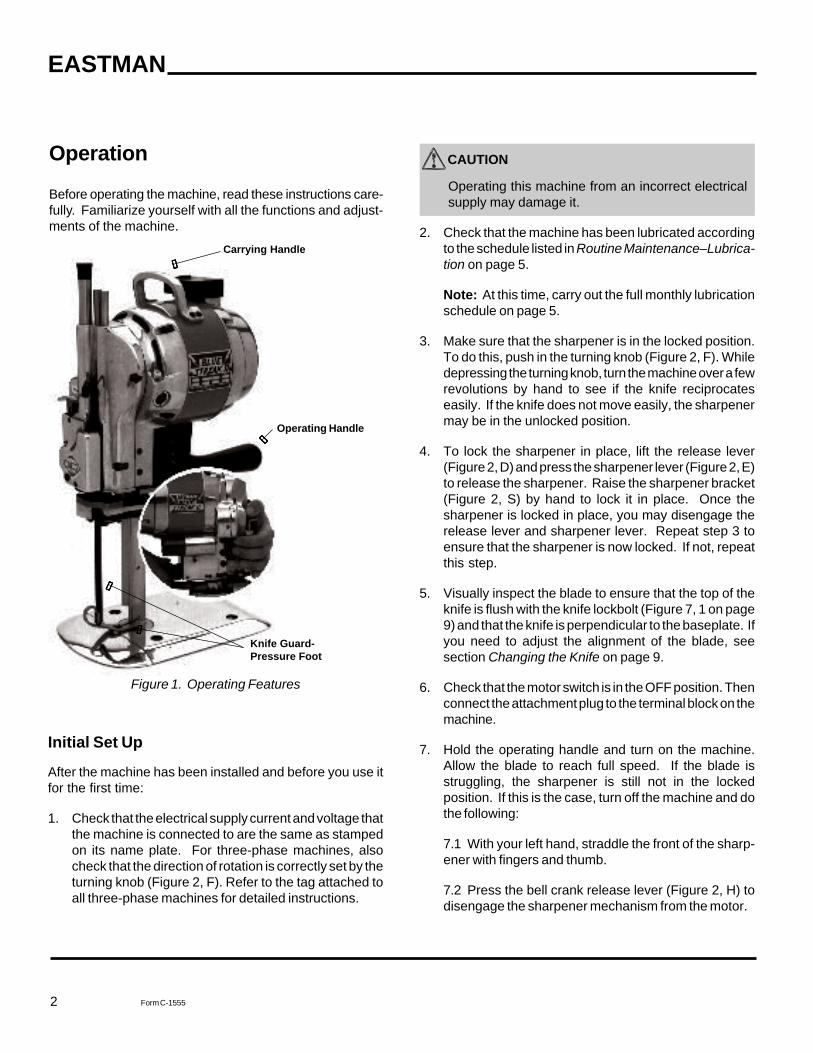
Figure 1. Operating Features
Initial Set Up
After the machine has been installed and before you use itfor the first time:
1. Check that the electrical supply current and voltage thatthe machine is connected to are the same as stampedon its name plate. For three-phase machines, alsocheck that the direction of rotation is correctly set by theturning knob (Figure 2, F). Refer to the tag attached toall three-phase machines for detailed instructions.
Operating Handle
Knife Guard-Pressure Foot
Carrying Handle
3Form C-1555
7.3 With your right hand, hold the operating handleand turn on the motor switch. Allow the motor togather full speed and then release the release lever.This automatically returns the sharpener to the lockedposition.
CAUTION
Turn the motor on and off a few times before runningthe machine continuously. This permits the oil to warmup and flow easily into the close-fitting moving parts.Failure to do this may result in damage to your ma-chine.
The machine is now ready for use.
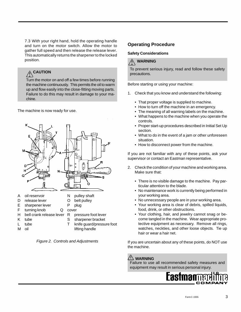
A oil reservoir N pulley shaftD release lever O belt pulleyE sharpener lever P plugF turning knob Q coverH bell crank release lever R pressure foot leverK tube S sharpener bracketL tube T knife guard/pressure footM oil lifting handle
Figure 2. Controls and Adjustments
Operating Procedure
Safety Considerations
WARNING
To prevent serious injury, read and follow these safetyprecautions.
Before starting or using your machine:
1. Check that you know and understand the following:
• That proper voltage is supplied to machine.• How to turn off the machine in an emergency.• The meaning of all warning labels on the machine.• What happens to the machine when you operate the
controls.• Proper start-up procedures described in Initial Set Up
section.• What to do in the event of a jam or other unforeseen
situation.• How to disconnect power from the machine.
If you are not familiar with any of these points, ask yoursupervisor or contact an Eastman representative.
2. Check the condition of your machine and working area.Make sure that:
• There is no visible damage to the machine. Pay par-ticular attention to the blade.
• No maintenance work is currently being performed inyour working area.
• No unnecessary people are in your working area.• Your working area is clear of debris, spilled liquids,
food, drink, or other obstructions.• Your clothing, hair, and jewelry cannot snag or be-
come tangled in the machine. Wear appropriate pro-tective equipment as necessary. Remove all rings,watches, neckties, and other loose objects. Tie uphair or wear a hair net.
If you are uncertain about any of these points, do NOT usethe machine.
WARNINGFailure to use all recommended safety measures andequipment may result in serious personal injury.
4
EASTMAN
Form C-1555
Turning Off the MachineWhen you have finished using your machine:
1. Position the power switch to off.
2. Make sure the knife guard/pressure foot is lowered to thebaseplate by depressing the pressure foot lever (Figure2, R).
3. Disconnect the attachment plug from the power source.
4. In cold weather, ensure that the machine is kept in awarm place when not in use.
Routine Maintenance
WARNING
Always unplug the machine before performing mainte-nance, adjustments, or repairs.
WARNING
After servicing the machine, always make sure the platebolt nut is securely fastened (Figure 3, X on page 6)before resuming cutting operation.
Care of the Machine
To ensure proper operation of your machine, carry out thefollowing procedures at the intervals indicated. If you useyour machine intensively, consider performing these proce-dures more often.
DailyRemove the knife and clean the knife slides with the slotcleaner (Figure 7, 2 on page 9) included with machine. Toprevent undue accumulation of lint, do NOT oil the platerollers. If the rollers stick, remove them from the plate andwash them in cleaning solvent.
Starting the MachineIf you have had the machine less than one month or if it hasstood idle for any length of time, turn the motor on and off afew times before running it continuously. This permits theoil to warm up and flow easily into the close-fitting movingparts.
CAUTION
Failure to warm up your machine adequately may dam-age the motor.
Making a Cut
WARNING
Failure to keep hands, arms, and hair away from the knifearea at all times may result in serious personal injury.
1. Bring the machine up to the material spread.
2. Raise the knife guard/pressure foot by depressing thepressure foot lever (Figure 2, R) and lifting the knifeguard/pressure foot lifting handle (Figure 2, T). Raisethe pressure foot only enough to clear the material beingcut.
3. Turn on the machine, allow the blade to reach full speed,and enter the fabric.
4. Using the pressure foot lever (Figure 2, R) and the knifeguard/pressure foot lifting handle (Figure 2, T), lower thepressure foot so that it is slightly above the materialbeing cut. This will prevent the material from reciprocat-ing.
5. Begin cutting.
6. When you are not making a cut, or when the machine isnot in use, keep the knife guard/pressure foot lowered tothe baseplate by depressing the pressure foot lever(Figure 2, R).
7. Turn off the machine when not cutting fabric.
5Form C-1555
• Tubes at locations shown as Figure 2, K and L.• Pulley shaft shown as Figure 2, N.• Belt pulley shown as Figure 2, O.
Monthly
1. Carry out the Daily and Weekly lubrication schedulesabove.
2. Remove the plug (Figure 2, P) and insert a grease tube.Squeeze an amount of grease approximately the size ofa pea into the opening.
WARNING
Routinely check the tightness of the operating handle toensure a secure connection.
Sharpening the Knife
Sharpen the knife at frequent intervals or whenever you feelit is not cutting adequately:
1. Take the machine out of the lay.
2. Drop the knife guard/pressure foot using the pressurefoot lever (Figure 2, R on page 3), located next to themachine operating handle.
3. Press the sharpener lever (Figure 2, E) downward witha slow, firm pressure to engage the sharpening mecha-nism. Too fast a lever action may cause the lever tolock. If this occurs, lift the release lever (Figure 2, D) andstart over again.
Removing the Sharpener
1. Disconnect the machine from the power source.
2. Using the turning knob (Figure 2, F) raise the blade to topposition.
3. Press the sharpener lever (Figure 3, E on page 6)approximately halfway down and to the neutral position,and lower the sharpener by hand.
Twice WeeklyUse an approved air hose or bellows to blow any lint fromaround the motor and sharpener.
WARNING
Failure to wear eye protection when using air hose orbellows may result in serious eye or facial injuries.
WeeklyRemove the cover (Figure 2, Q) and clean any lint fromaround the screw mechanism in the sharpener.
Lubrication
Lubricate your machine according to the followingschedule:
CAUTION
Use only specially compounded Eastman 30-weight, non-detergent oil. Use of sewing machine oil or detergent oilmay result in damage to your machine. Do not oil thebaseplate rollers. Use of an excessive amount of oilmay damage the machine.
Daily
1. Place two drops of oil at each of the two locations shownin Figure 2, M. Use an oil can with a small spout. (Asuitable oil can is furnished with the machine.)
2. Fill the oil reservoir (Figure 2, A) for continuous use. Ifyou only use the machine intermittently, you can useless oil.
Weekly
1. Carry out the Daily lubrication schedule above.
2. Apply one drop of oil only to each of the following:
6
EASTMAN
Form C-1555
WARNING
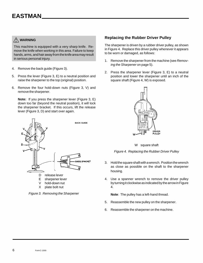
This machine is equipped with a very sharp knife. Re-move the knife when working in this area. Failure to keephands, arms, and hair away from the knife area may resultin serious personal injury.
4. Remove the back guide (Figure 3).
5. Press the lever (Figure 3, E) to a neutral position andraise the sharpener to the top (original) position.
6. Remove the four hold-down nuts (Figure 3, V) andremove the sharpener.
Note: If you press the sharpener lever (Figure 3, E)down too far (beyond the neutral position), it will lockthe sharpener bracket. If this occurs, lift the releaselever (Figure 3, D) and start over again.
D release leverE sharpener leverV hold-down nutX plate bolt nut
Figure 3. Removing the Sharpener
Replacing the Rubber Driver Pulley
The sharpener is driven by a rubber driver pulley, as shownin Figure 4. Replace this driver pulley whenever it appearsto be worn or damaged, as follows:
1. Remove the sharpener from the machine (see Remov-ing the Sharpener on page 5).
2. Press the sharpener lever (Figure 3, E) to a neutralposition and lower the sharpener until an inch of thesquare shaft (Figure 4, W) is exposed.
W square shaft
Figure 4. Replacing the Rubber Driver Pulley
3. Hold the square shaft with a wrench. Position the wrenchas close as possible on the shaft to the sharpenerhousing.
4. Use a spanner wrench to remove the driver pulleyby turning it clockwise as indicated by the arrow in Figure4.
Note: The pulley has a left-hand thread.
5. Reassemble the new pulley on the sharpener.
6. Reassemble the sharpener on the machine.
BACK GUIDE
X
7Form C-1555
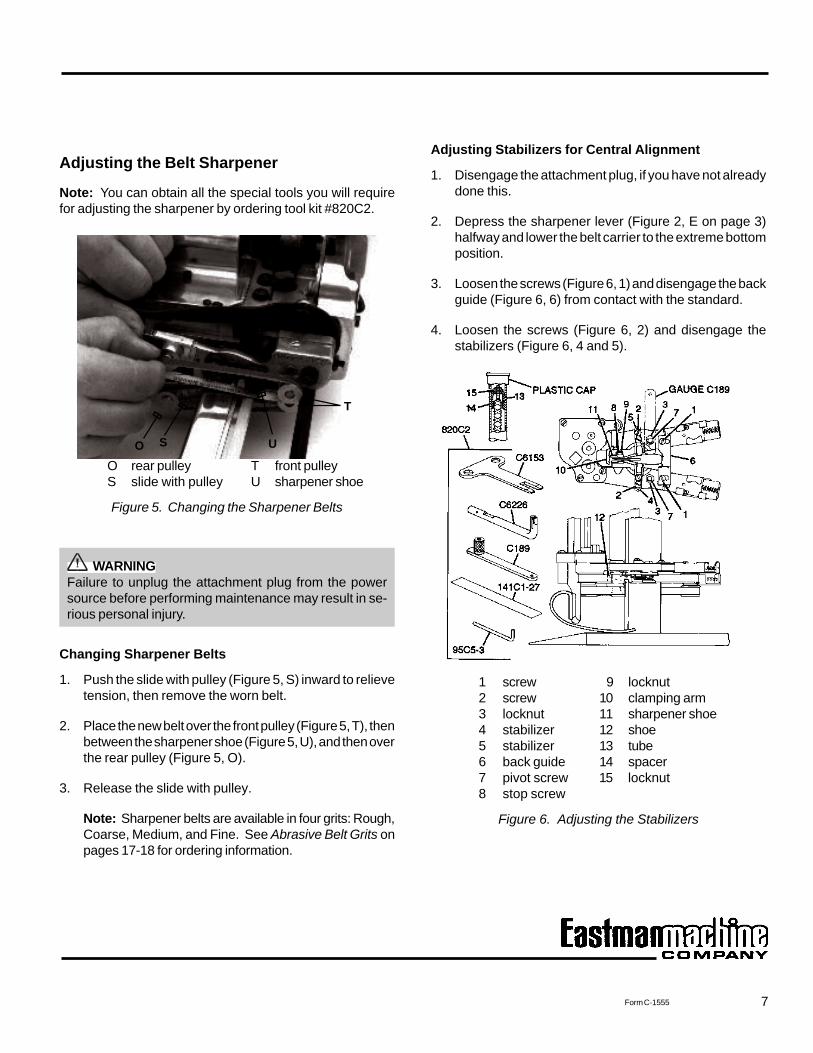
Adjusting the Belt Sharpener
Note: You can obtain all the special tools you will requirefor adjusting the sharpener by ordering tool kit #820C2.
O rear pulley T front pulleyS slide with pulley U sharpener shoe
Figure 5. Changing the Sharpener Belts
WARNINGFailure to unplug the attachment plug from the powersource before performing maintenance may result in se-rious personal injury.
Changing Sharpener Belts
1. Push the slide with pulley (Figure 5, S) inward to relievetension, then remove the worn belt.
2. Place the new belt over the front pulley (Figure 5, T), thenbetween the sharpener shoe (Figure 5, U), and then overthe rear pulley (Figure 5, O).
3. Release the slide with pulley.
Note: Sharpener belts are available in four grits: Rough,Coarse, Medium, and Fine. See Abrasive Belt Grits onpages 17-18 for ordering information.
Adjusting Stabilizers for Central Alignment
1. Disengage the attachment plug, if you have not alreadydone this.
2. Depress the sharpener lever (Figure 2, E on page 3)halfway and lower the belt carrier to the extreme bottomposition.
3. Loosen the screws (Figure 6, 1) and disengage the backguide (Figure 6, 6) from contact with the standard.
4. Loosen the screws (Figure 6, 2) and disengage thestabilizers (Figure 6, 4 and 5).
1 screw 9 locknut2 screw 10 clamping arm3 locknut 11 sharpener shoe4 stabilizer 12 shoe5 stabilizer 13 tube6 back guide 14 spacer7 pivot screw 15 locknut8 stop screw
Figure 6. Adjusting the Stabilizers
T
USO
8
EASTMAN
Form C-1555
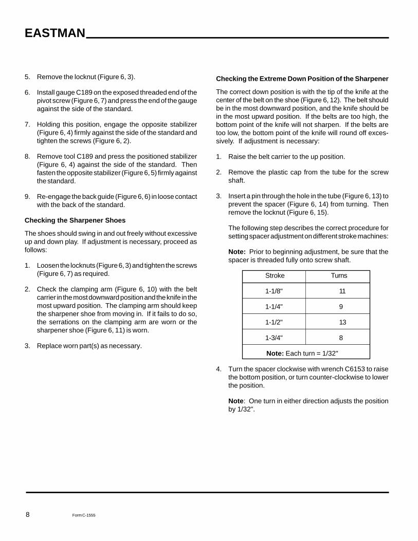
Checking the Extreme Down Position of the Sharpener
The correct down position is with the tip of the knife at thecenter of the belt on the shoe (Figure 6, 12). The belt shouldbe in the most downward position, and the knife should bein the most upward position. If the belts are too high, thebottom point of the knife will not sharpen. If the belts aretoo low, the bottom point of the knife will round off exces-sively. If adjustment is necessary:
1. Raise the belt carrier to the up position.
2. Remove the plastic cap from the tube for the screwshaft.
3. Insert a pin through the hole in the tube (Figure 6, 13) toprevent the spacer (Figure 6, 14) from turning. Thenremove the locknut (Figure 6, 15).
The following step describes the correct procedure forsetting spacer adjustment on different stroke machines:
Note: Prior to beginning adjustment, be sure that thespacer is threaded fully onto screw shaft.
Stroke Turns
1-1/8" 11
1-1/4" 9
1-1/2" 13
1-3/4" 8
Note: Each turn = 1/32"
4. Turn the spacer clockwise with wrench C6153 to raisethe bottom position, or turn counter-clockwise to lowerthe position.
Note: One turn in either direction adjusts the positionby 1/32".
5. Remove the locknut (Figure 6, 3).
6. Install gauge C189 on the exposed threaded end of thepivot screw (Figure 6, 7) and press the end of the gaugeagainst the side of the standard.
7. Holding this position, engage the opposite stabilizer(Figure 6, 4) firmly against the side of the standard andtighten the screws (Figure 6, 2).
8. Remove tool C189 and press the positioned stabilizer(Figure 6, 4) against the side of the standard. Thenfasten the opposite stabilizer (Figure 6, 5) firmly againstthe standard.
9. Re-engage the back guide (Figure 6, 6) in loose contactwith the back of the standard.
Checking the Sharpener Shoes
The shoes should swing in and out freely without excessiveup and down play. If adjustment is necessary, proceed asfollows:
1. Loosen the locknuts (Figure 6, 3) and tighten the screws(Figure 6, 7) as required.
2. Check the clamping arm (Figure 6, 10) with the beltcarrier in the most downward position and the knife in themost upward position. The clamping arm should keepthe sharpener shoe from moving in. If it fails to do so,the serrations on the clamping arm are worn or thesharpener shoe (Figure 6, 11) is worn.
3. Replace worn part(s) as necessary.
9Form C-1555
5. When the spacer is adjusted, use the pin to hold thespacer in position, reassemble, and tighten the locknut(Figure 6, 15).
6. Replace the plastic cap.
Checking the Stop Screw on the Sharpener Shoe
1. With new belts on the carrier, insert .010 feeler gauge#141C1-27 between the stop screw (Figure 6, 8) and theknife. Ensure that the clamping arm (Figure 6, 10) hasbeen released from the sharpener shoe (Figure 6, 11).The gauge should just fill the space between the screwand the knife.
2. If an adjustment is necessary, loosen the locknut(Figure 6, 9). Adjust the set screw to the proper spacing,and re-tighten the locknut.
Check the Width of the Bevel on the Knife
The bevel should be approximately 1/16" on both sides. Ifit is not:
1. Install a new knife and new belts.
2. Color the bevel with a wax pencil.
3. Run the sharpener up and down the knife several times.
4. If an adjustment is required for Flex-Pad shoes, inserttool C6226 over the belt guide pad. Move the free end ofthe tool to the rear to increase the bevel, or to the frontto decrease bevel.
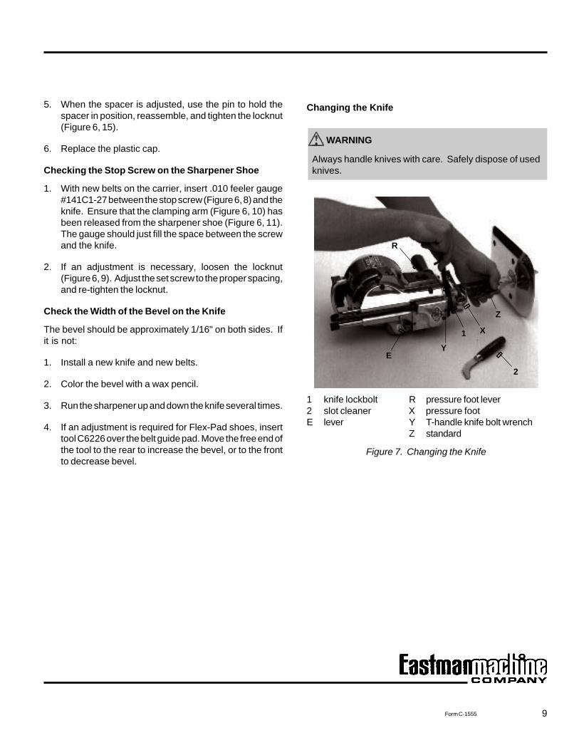
Changing the Knife
WARNING
Always handle knives with care. Safely dispose of usedknives.
1 knife lockbolt R pressure foot lever2 slot cleaner X pressure footE lever Y T-handle knife bolt wrench
Z standard
Figure 7. Changing the Knife
2
Z
X1Y
E
R
10
EASTMAN
Form C-1555
Changing the Knife (continued)
WARNING
Unplug the attachment plug from power source.
1. Make sure the sharpener is in the locked position.
2. Raise the pressure foot (Figure 7, X on page 9) to the topposition using the pressure foot lever (Figure 7, R),which is located next to the machine operating handle.
3. Lay the machine on a table, as shown in Figure 7.
4. Press in the turning knob (Figure 2, F on page 3) and turnthe knife to the bottom position.
5. Insert the T-handle knife bolt wrench (Figure 7, Y) andloosen the knife lockbolt (Figure 7, 1).
6. Remove the knife through the bottom of the standard(Figure 7, Z).
7. After removing the knife, clean the knife slot in thestandard with the slot cleaner (Figure 7, 2).
8. Insert a new knife in the knife slot. Be sure to set theknife tightly against the knife lockbolt. Hold the bottomof the knife against the back of the slot in the standardand tighten the knife lockbolt.
9. After tightening the knife lockbolt, check to see if theknife runs freely in the standard by rotating the turningknob.
10. Install new sharpener belts and operate the sharpenerthree or four times before starting to cut.
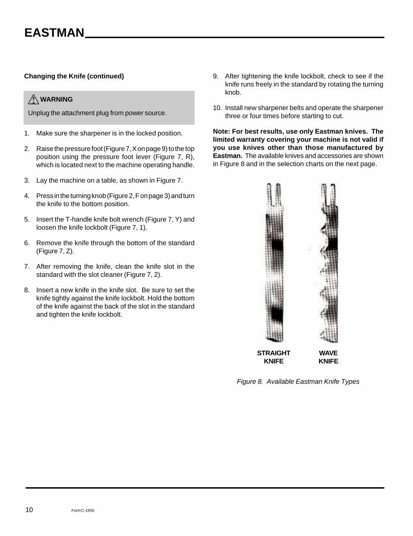
Note: For best results, use only Eastman knives. Thelimited warranty covering your machine is not valid ifyou use knives other than those manufactured byEastman. The available knives and accessories are shownin Figure 8 and in the selection charts on the next page.
STRAIGHT WAVEKNIFE KNIFE
Figure 8. Available Eastman Knife Types
11Form C-1555
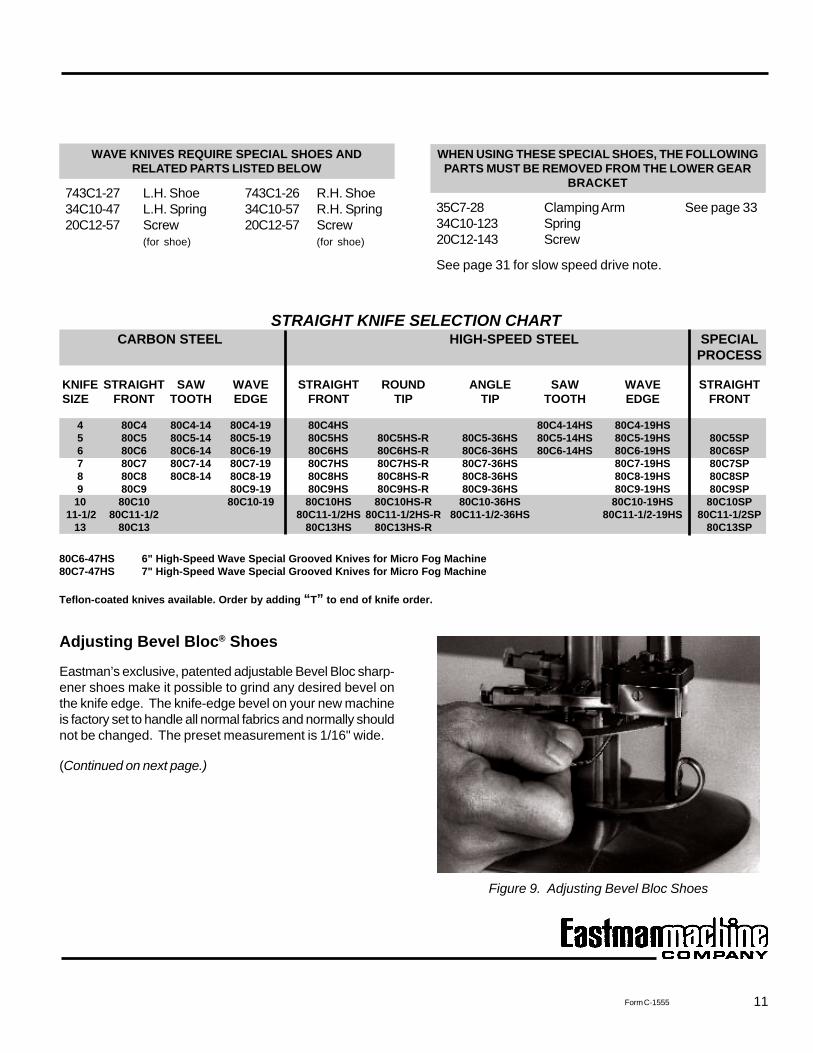
STRAIGHT KNIFE SELECTION CHARTCARBON STEEL HIGH-SPEED STEEL SPECIAL
PROCESS
KNIFE STRAIGHT SAW WAVE STRAIGHT ROUND ANGLE SAW WAVE STRAIGHTSIZE FRONT TOOTH EDGE FRONT TIP TIP TOOTH EDGE FRONT
4 80C4 80C4-14 80C4-19 80C4HS 80C4-14HS 80C4-19HS5 80C5 80C5-14 80C5-19 80C5HS 80C5HS-R 80C5-36HS 80C5-14HS 80C5-19HS 80C5SP6 80C6 80C6-14 80C6-19 80C6HS 80C6HS-R 80C6-36HS 80C6-14HS 80C6-19HS 80C6SP7 80C7 80C7-14 80C7-19 80C7HS 80C7HS-R 80C7-36HS 80C7-19HS 80C7SP8 80C8 80C8-14 80C8-19 80C8HS 80C8HS-R 80C8-36HS 80C8-19HS 80C8SP9 80C9 80C9-19 80C9HS 80C9HS-R 80C9-36HS 80C9-19HS 80C9SP
10 80C10 80C10-19 80C10HS 80C10HS-R 80C10-36HS 80C10-19HS 80C10SP11-1/2 80C11-1/2 80C11-1/2HS 80C11-1/2HS-R 80C11-1/2-36HS 80C11-1/2-19HS 80C11-1/2SP
13 80C13 80C13HS 80C13HS-R 80C13SP
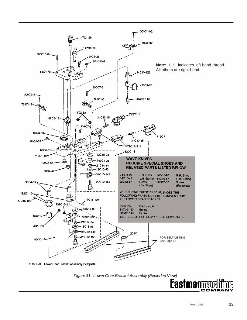
WHEN USING THESE SPECIAL SHOES, THE FOLLOWINGPARTS MUST BE REMOVED FROM THE LOWER GEAR
BRACKET
35C7-28 Clamping Arm See page 3334C10-123 Spring20C12-143 Screw
See page 31 for slow speed drive note.
WAVE KNIVES REQUIRE SPECIAL SHOES ANDRELATED PARTS LISTED BELOW
743C1-27 L.H. Shoe 743C1-26 R.H. Shoe34C10-47 L.H. Spring 34C10-57 R.H. Spring20C12-57 Screw 20C12-57 Screw
(for shoe) (for shoe)
80C6-47HS 6" High-Speed Wave Special Grooved Knives for Micro Fog Machine80C7-47HS 7" High-Speed Wave Special Grooved Knives for Micro Fog Machine
Teflon-coated knives available. Order by adding “T” to end of knife order.
Figure 9. Adjusting Bevel Bloc Shoes
Adjusting Bevel Bloc® Shoes
Eastman’s exclusive, patented adjustable Bevel Bloc sharp-ener shoes make it possible to grind any desired bevel onthe knife edge. The knife-edge bevel on your new machineis factory set to handle all normal fabrics and normally shouldnot be changed. The preset measurement is 1/16" wide.
(Continued on next page.)
12
EASTMAN
Form C-1555
Adjusting Bevel Bloc® Shoes (continued)
If you need to adjust the bevel on the knife edge to a differ-ent length, proceed as follows:
1. Disconnect the machine from the power source.
2. Lower the knife to the bottom of the stroke with themachine turning knob (Figure 2, F on page 3).
3. Lower the sharpener manually, by holding the sharpenerlever (Figure 2, E) halfway down to its neutral position.
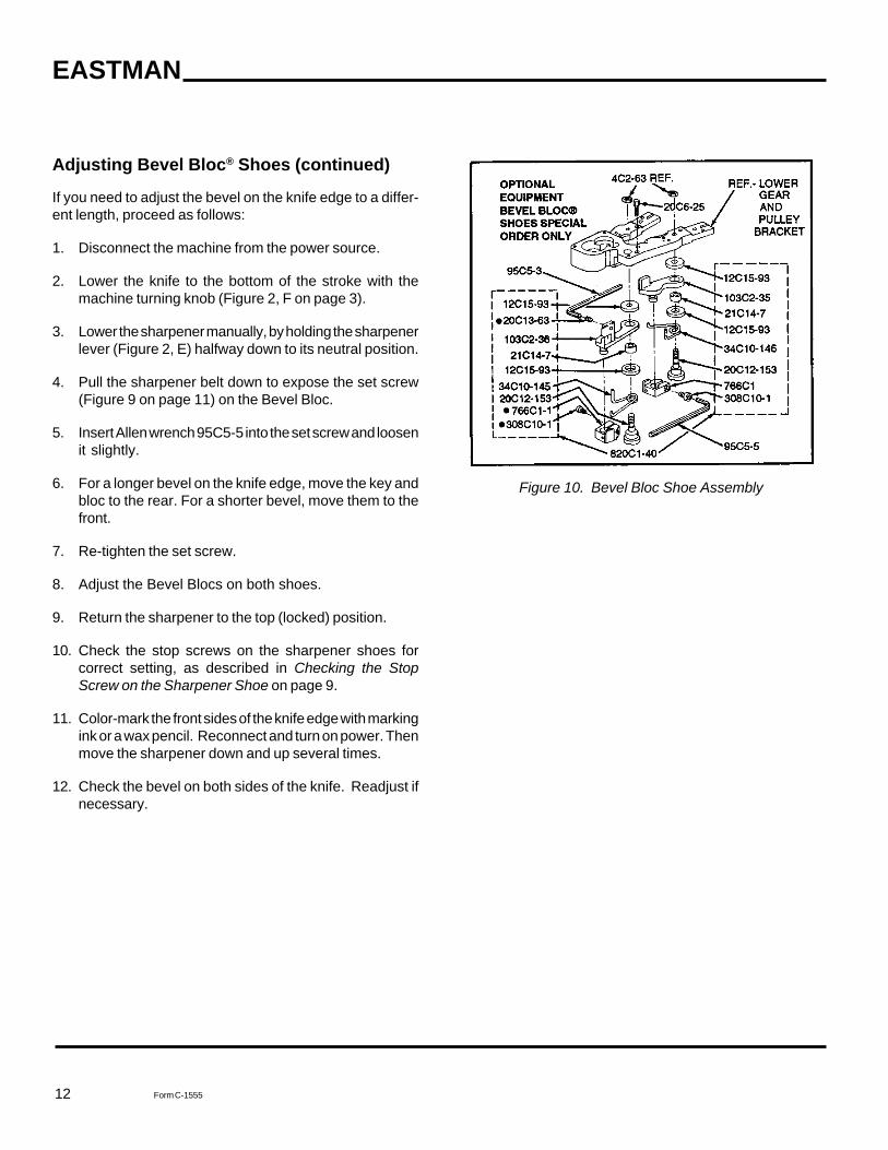
4. Pull the sharpener belt down to expose the set screw(Figure 9 on page 11) on the Bevel Bloc.
5. Insert Allen wrench 95C5-5 into the set screw and loosenit slightly.
6. For a longer bevel on the knife edge, move the key andbloc to the rear. For a shorter bevel, move them to thefront.
7. Re-tighten the set screw.
8. Adjust the Bevel Blocs on both shoes.
9. Return the sharpener to the top (locked) position.
10. Check the stop screws on the sharpener shoes forcorrect setting, as described in Checking the StopScrew on the Sharpener Shoe on page 9.
11. Color-mark the front sides of the knife edge with markingink or a wax pencil. Reconnect and turn on power. Thenmove the sharpener down and up several times.
12. Check the bevel on both sides of the knife. Readjust ifnecessary.
Figure 10. Bevel Bloc Shoe Assembly
13Form C-1555
SUBASSEMBLY 743C3-1 INCLUDES:
20C13-63 Screw, Set103C2-36 Shoe, Sharpener L.H.766C1-1 Bevel Bloc Assembly L.H.308C10-1 Screw, Socket 6/32" x 5/16" (2 required)
PART NO. DESCRIPTION
4C2-63 L.H. Nut (2 required)715C1-16 Lower Gear Bracket Complete 5"-10" Knife715C1-18 Lwr. Gear Bracket Com. 11 1/2"-13" Knife820C1-40 Conversion Kit R.H. & L.H. Shoes
INCLUDES THE FOLLOWING:
12C15-93 Washer Shoe (4 required)20C6-25* Screw Adjust20C12-153 Screw, Sharpener Shoe (2 required)20C13-63 Screw, Set21C14-7 Bushing, Shoe (2 required)34C10-145 Spring Shoe L.H.34C10-146 Spring Shoe R.H.95C5-3 Wrench, Allen95C5-5* Wrench, Allen103C2-35 Shoe, Sharpener R.H.103C2-36 Shoe, Sharpener L.H.308C10-1* Screw, Socket 6/32" x 5/16" (2 required)766C1* Bevel Block Assembly R.H.766C1-1* Bevel Block Assembly L.H.820C1-39 Conversion Kit includes * parts above.
Note: 766C1 and 766C1-1 are sold in pairs with kits only.
SUBASSEMBLY 743C3 INCLUDES:
103C2-35 Shoe, Sharpener R.H.766C1 Bevel Block Assembly R.H.308C10-1 Screw, Socket 6/32" x 5/16" (2 required)
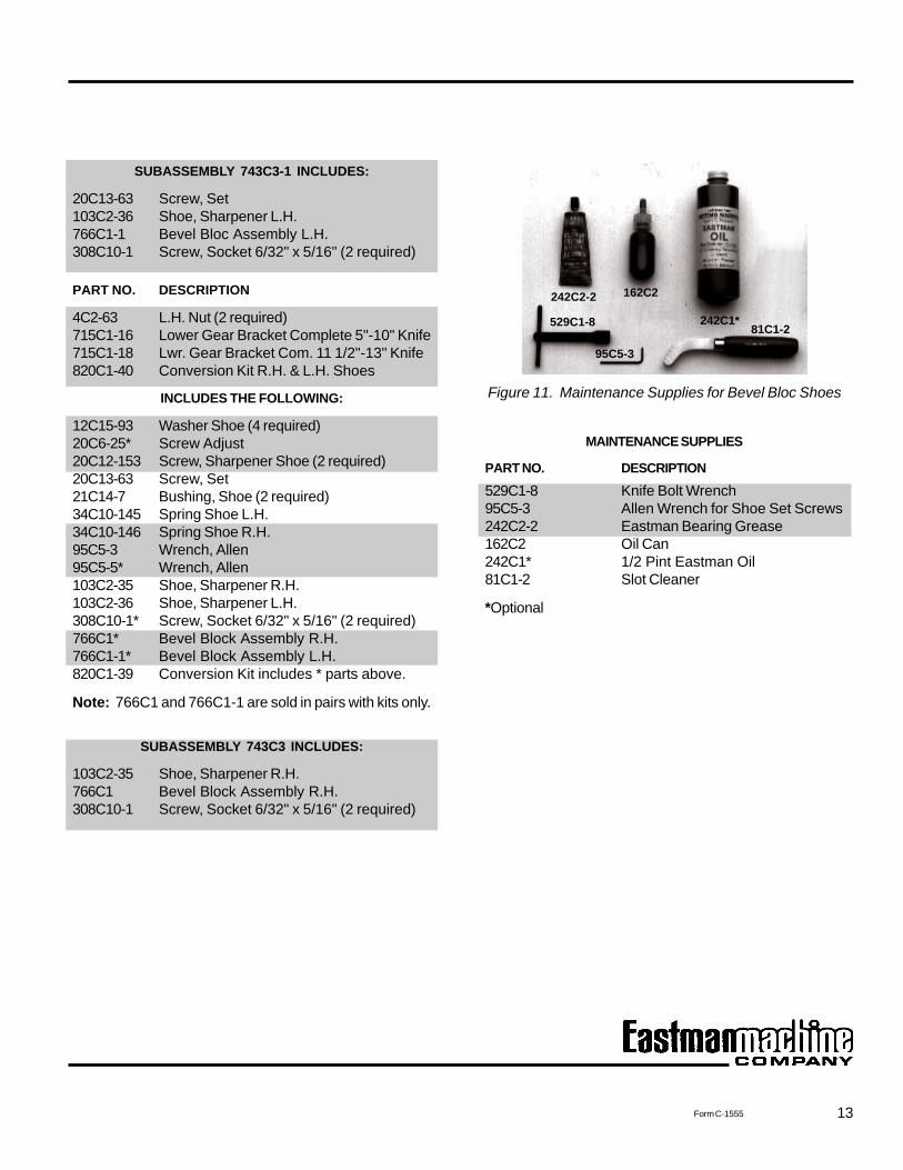
Figure 11. Maintenance Supplies for Bevel Bloc Shoes
MAINTENANCE SUPPLIES
PART NO. DESCRIPTION
529C1-8 Knife Bolt Wrench95C5-3 Allen Wrench for Shoe Set Screws242C2-2 Eastman Bearing Grease162C2 Oil Can242C1* 1/2 Pint Eastman Oil81C1-2 Slot Cleaner
*Optional
529C1-8 81C1-2
162C2
242C1*
95C5-3
242C2-2
14
EASTMAN
Form C-1555
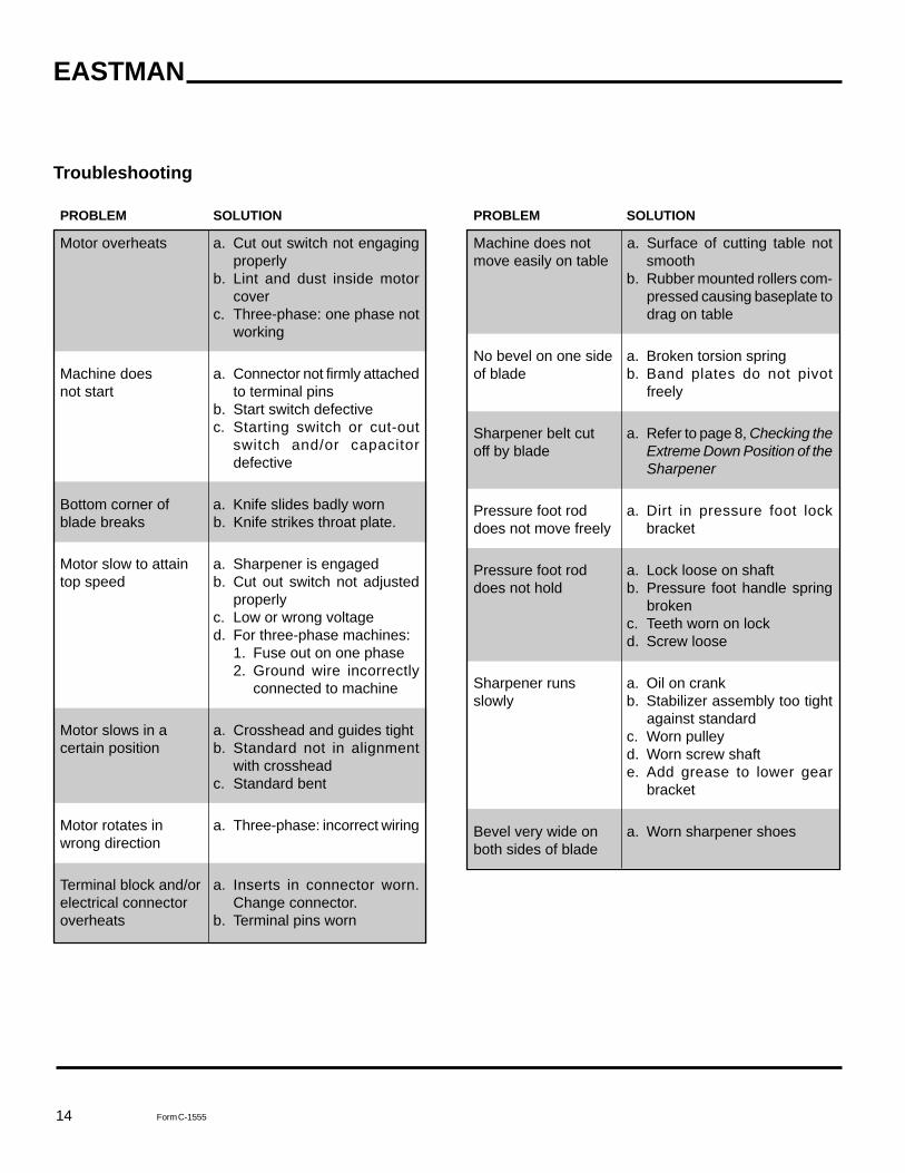
PROBLEM SOLUTION
Machine does not a. Surface of cutting table notmove easily on table smooth
b. Rubber mounted rollers com-pressed causing baseplate todrag on table
No bevel on one side a. Broken torsion springof blade b. Band plates do not pivot
freely
Sharpener belt cut a. Refer to page 8, Checking theoff by blade Extreme Down Position of the
Sharpener
Pressure foot rod a. Dirt in pressure foot lockdoes not move freely bracket
Pressure foot rod a. Lock loose on shaftdoes not hold b. Pressure foot handle spring
brokenc. Teeth worn on lockd. Screw loose
Sharpener runs a. Oil on crankslowly b. Stabilizer assembly too tight
against standardc. Worn pulleyd. Worn screw shafte. Add grease to lower gear
bracket
Bevel very wide on a. Worn sharpener shoesboth sides of blade
Troubleshooting
PROBLEM SOLUTION
Motor overheats a. Cut out switch not engagingproperly
b. Lint and dust inside motorcover
c. Three-phase: one phase notworking
Machine does a. Connector not firmly attachednot start to terminal pins
b. Start switch defectivec. Starting switch or cut-out
switch and/or capacitordefective
Bottom corner of a. Knife slides badly wornblade breaks b. Knife strikes throat plate.
Motor slow to attain a. Sharpener is engagedtop speed b. Cut out switch not adjusted
properlyc. Low or wrong voltaged. For three-phase machines:
1. Fuse out on one phase2. Ground wire incorrectly
connected to machine
Motor slows in a a. Crosshead and guides tightcertain position b. Standard not in alignment
with crossheadc. Standard bent
Motor rotates in a. Three-phase: incorrect wiringwrong direction
Terminal block and/or a. Inserts in connector worn.electrical connector Change connector.overheats b. Terminal pins worn
15Form C-1555
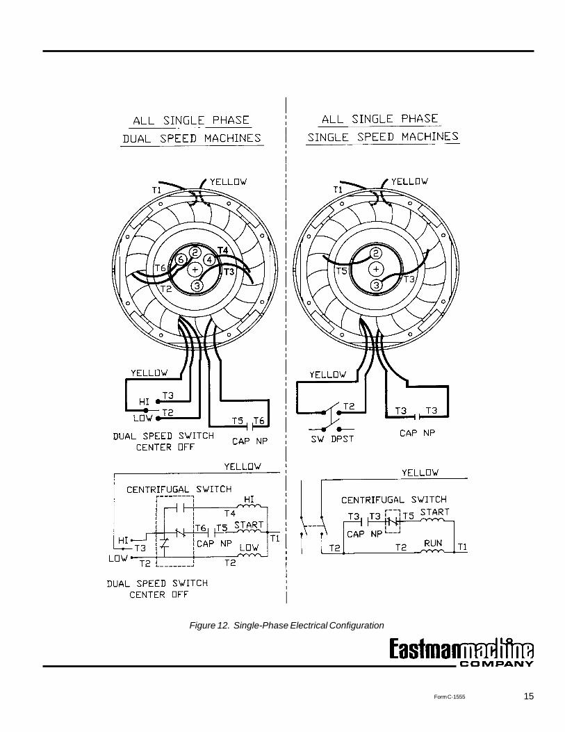
Figure 12. Single-Phase Electrical Configuration
16
EASTMAN
Form C-1555
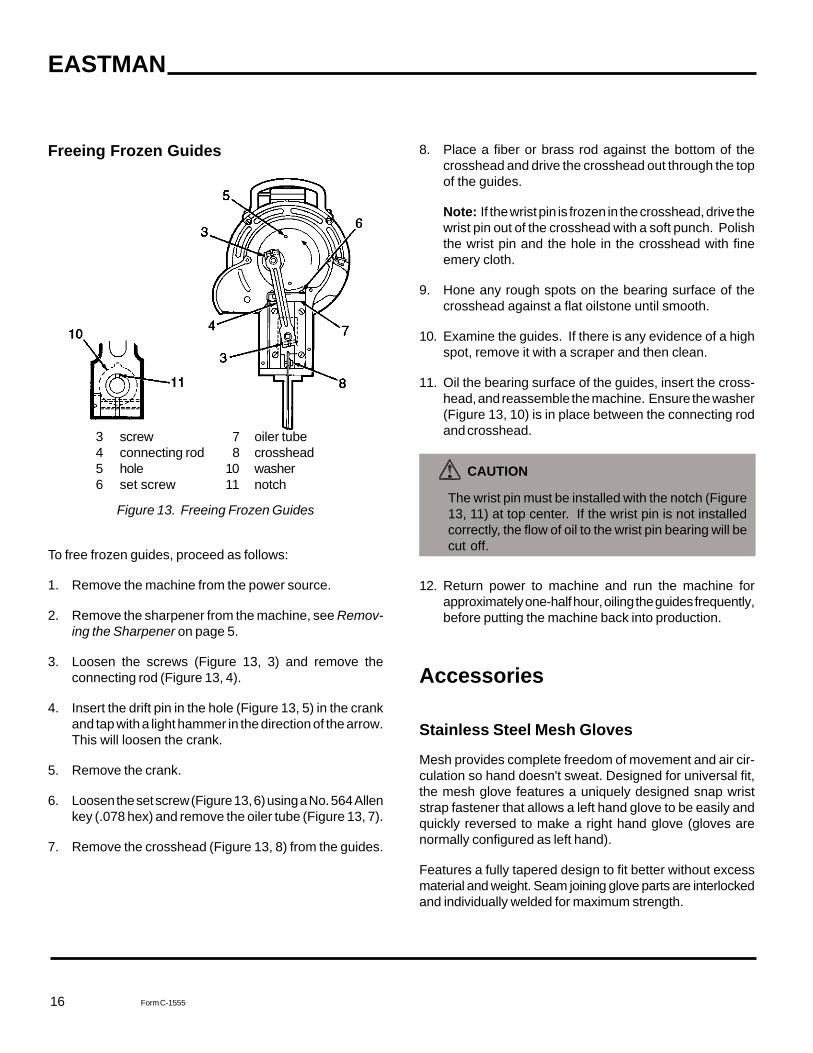
8. Place a fiber or brass rod against the bottom of thecrosshead and drive the crosshead out through the topof the guides.
Note: If the wrist pin is frozen in the crosshead, drive thewrist pin out of the crosshead with a soft punch. Polishthe wrist pin and the hole in the crosshead with fineemery cloth.
9. Hone any rough spots on the bearing surface of thecrosshead against a flat oilstone until smooth.
10. Examine the guides. If there is any evidence of a highspot, remove it with a scraper and then clean.
11. Oil the bearing surface of the guides, insert the cross-head, and reassemble the machine. Ensure the washer(Figure 13, 10) is in place between the connecting rodand crosshead.
CAUTION
The wrist pin must be installed with the notch (Figure13, 11) at top center. If the wrist pin is not installedcorrectly, the flow of oil to the wrist pin bearing will becut off.
12. Return power to machine and run the machine forapproximately one-half hour, oiling the guides frequently,before putting the machine back into production.
Accessories
Stainless Steel Mesh Gloves
Mesh provides complete freedom of movement and air cir-culation so hand doesn't sweat. Designed for universal fit,the mesh glove features a uniquely designed snap wriststrap fastener that allows a left hand glove to be easily andquickly reversed to make a right hand glove (gloves arenormally configured as left hand).
Features a fully tapered design to fit better without excessmaterial and weight. Seam joining glove parts are interlockedand individually welded for maximum strength.
Freeing Frozen Guides
3 screw 7 oiler tube4 connecting rod 8 crosshead5 hole 10 washer6 set screw 11 notch
Figure 13. Freeing Frozen Guides
To free frozen guides, proceed as follows:
1. Remove the machine from the power source.
2. Remove the sharpener from the machine, see Remov-ing the Sharpener on page 5.
3. Loosen the screws (Figure 13, 3) and remove theconnecting rod (Figure 13, 4).
4. Insert the drift pin in the hole (Figure 13, 5) in the crankand tap with a light hammer in the direction of the arrow.This will loosen the crank.
5. Remove the crank.
6. Loosen the set screw (Figure 13, 6) using a No. 564 Allenkey (.078 hex) and remove the oiler tube (Figure 13, 7).
7. Remove the crosshead (Figure 13, 8) from the guides.
17Form C-1555
Ordering Reference DescriptionLeft-Hand (see note for Right-Handed)GU300 XS 3 Finger, extra small, Snap-BuckleGU300 S 3 Finger, small, Snap-BuckleGU300 M 3 Finger, medium, Snap-BuckleGU300 L 3 Finger, large, Snap-BuckleGU300 XL 3 Finger, extra large, Snap-Buckle
GU500 XS 5 Finger, extra small, Snap-BuckleGU500 S 5 Finger, small, Snap-BuckleGU500 M 5 Finger, medium, Snap-BuckleGU500 L 5 Finger, large, Snap-BuckleGU500 XL 5 Finger, extra large, Snap-Buckle
Genuine Eastman Abrasive Belts
Eastman’s four abrasive belt grits offer an edge for everyfabric. For increased cutting efficiency, Eastman offers fourdifferent edges as produced by four different abrasive belts.These belt grits are available in convenient, color-codedboxes for easy identification.
Figure 15. Eastman Abrasive Belts
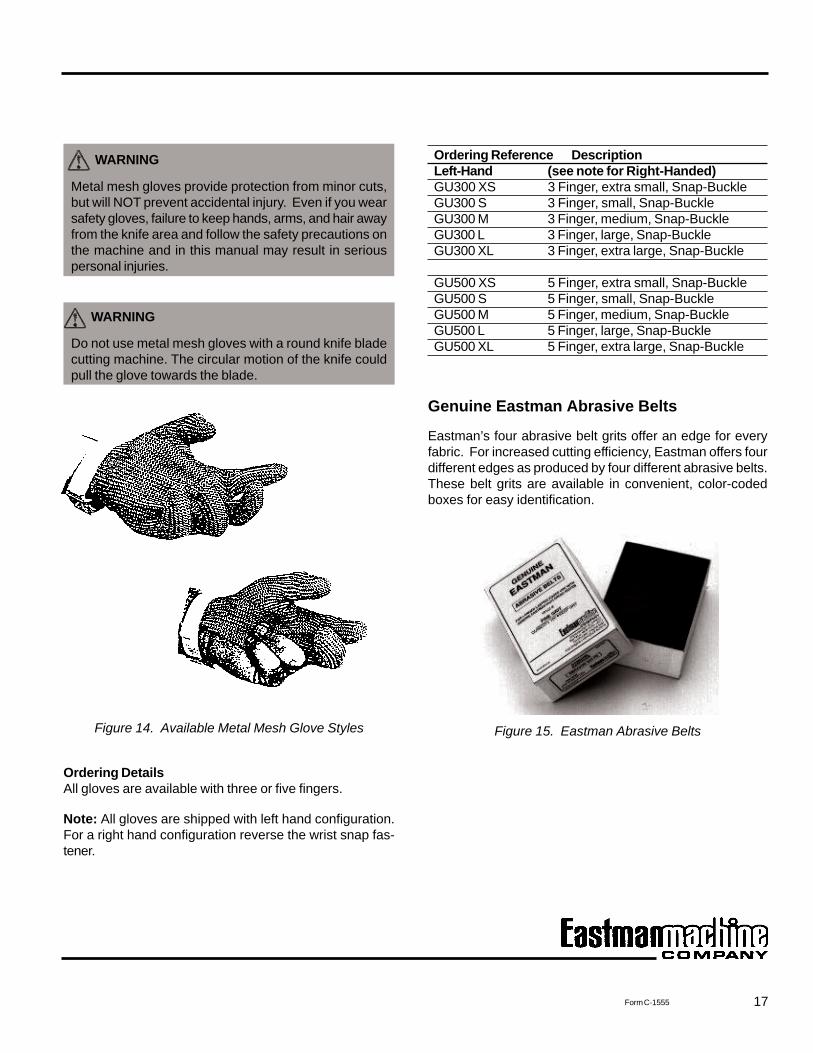
WARNING
Metal mesh gloves provide protection from minor cuts,but will NOT prevent accidental injury. Even if you wearsafety gloves, failure to keep hands, arms, and hair awayfrom the knife area and follow the safety precautions onthe machine and in this manual may result in seriouspersonal injuries.
WARNING
Do not use metal mesh gloves with a round knife bladecutting machine. The circular motion of the knife couldpull the glove towards the blade.
Figure 14. Available Metal Mesh Glove Styles
Ordering DetailsAll gloves are available with three or five fingers.
Note: All gloves are shipped with left hand configuration.For a right hand configuration reverse the wrist snap fas-tener.
18
EASTMAN
Form C-1555
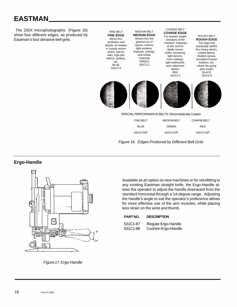
The 250X microphotographs (Figure 16)show four different edges, as produced byEastman’s four abrasive belt grits.
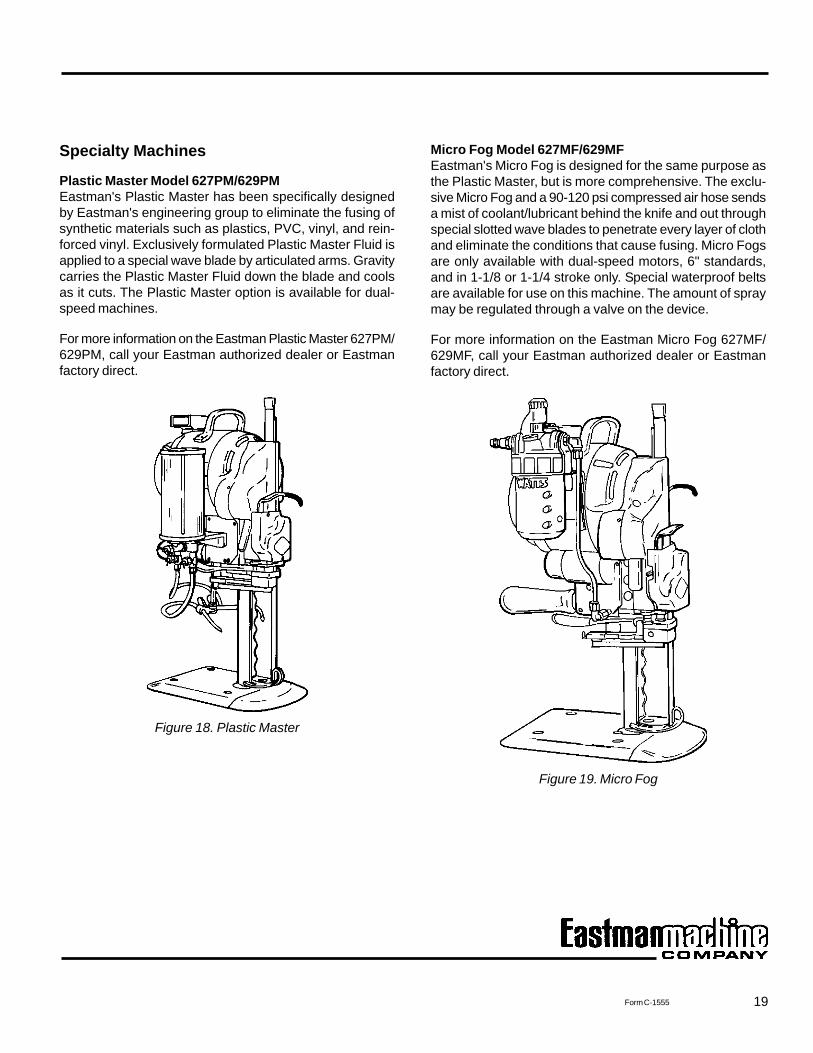
Available as an option on new machines or for retrofitting toany existing Eastman straight knife, the Ergo-Handle al-lows the operator to adjust the handle downward from thestandard horizontal through a 14-degree range. Adjustingthe handle’s angle to suit the operator’s preference allowsfor more effective use of the arm muscles, while placingless strain on the wrist and thumb.
PART NO. DESCRIPTION
531C1-87 Regular Ergo-Handle531C1-88 Cushion Ergo-Handle
SPECIAL PERFORMANCE BELTS: Electrostatically Coated
FINE BELT MEDIUM BELT COARSE BELT
BLUE GREEN RED
181C2-5SP 181C2-2SP 181C2-1SP
Figure 16. Edges Produced by Different Belt Grits
Ergo-Handle
Figure 17. Ergo-Handle
FINE BELTFINE EDGE
Slices thrusynthetics and
blends, for knittedor loosely woven
cloths, and forsilks, high-pile
fabrics, quilting,etc.
BLUE181C2-5
MEDIUM BELTMEDIUM EDGE
Shears thru thegeneral run of
rayons, cottons,light woolens,
tropicals, suitings,and similarmaterialsGREEN181C2-2
COARSE BELTCOARSE EDGEFor heavier weight
variations of the"medium" materials
at left, and forlightly woven
cloths, pocketing,light denims,
over-coatings,light leatherette,and rubberized
fabricsRED
181C2-1
ROUGH BELTROUGH EDGE
The edge thatpractically SAWSthru heavy denim,
coated fabrics,treated canvas,
simulated heavierleathers, etc.
where the goinggets tough!
BLACK181C2-6
19Form C-1555
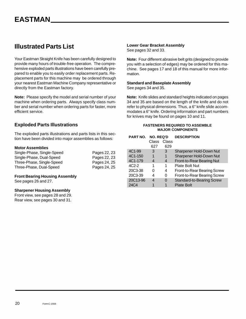
Specialty Machines
Plastic Master Model 627PM/629PMEastman's Plastic Master has been specifically designedby Eastman's engineering group to eliminate the fusing ofsynthetic materials such as plastics, PVC, vinyl, and rein-forced vinyl. Exclusively formulated Plastic Master Fluid isapplied to a special wave blade by articulated arms. Gravitycarries the Plastic Master Fluid down the blade and coolsas it cuts. The Plastic Master option is available for dual-speed machines.
For more information on the Eastman Plastic Master 627PM/629PM, call your Eastman authorized dealer or Eastmanfactory direct.
Figure 18. Plastic Master
Micro Fog Model 627MF/629MFEastman's Micro Fog is designed for the same purpose asthe Plastic Master, but is more comprehensive. The exclu-sive Micro Fog and a 90-120 psi compressed air hose sendsa mist of coolant/lubricant behind the knife and out throughspecial slotted wave blades to penetrate every layer of clothand eliminate the conditions that cause fusing. Micro Fogsare only available with dual-speed motors, 6" standards,and in 1-1/8 or 1-1/4 stroke only. Special waterproof beltsare available for use on this machine. The amount of spraymay be regulated through a valve on the device.
For more information on the Eastman Micro Fog 627MF/629MF, call your Eastman authorized dealer or Eastmanfactory direct.
Figure 19. Micro Fog
20
EASTMAN
Form C-1555
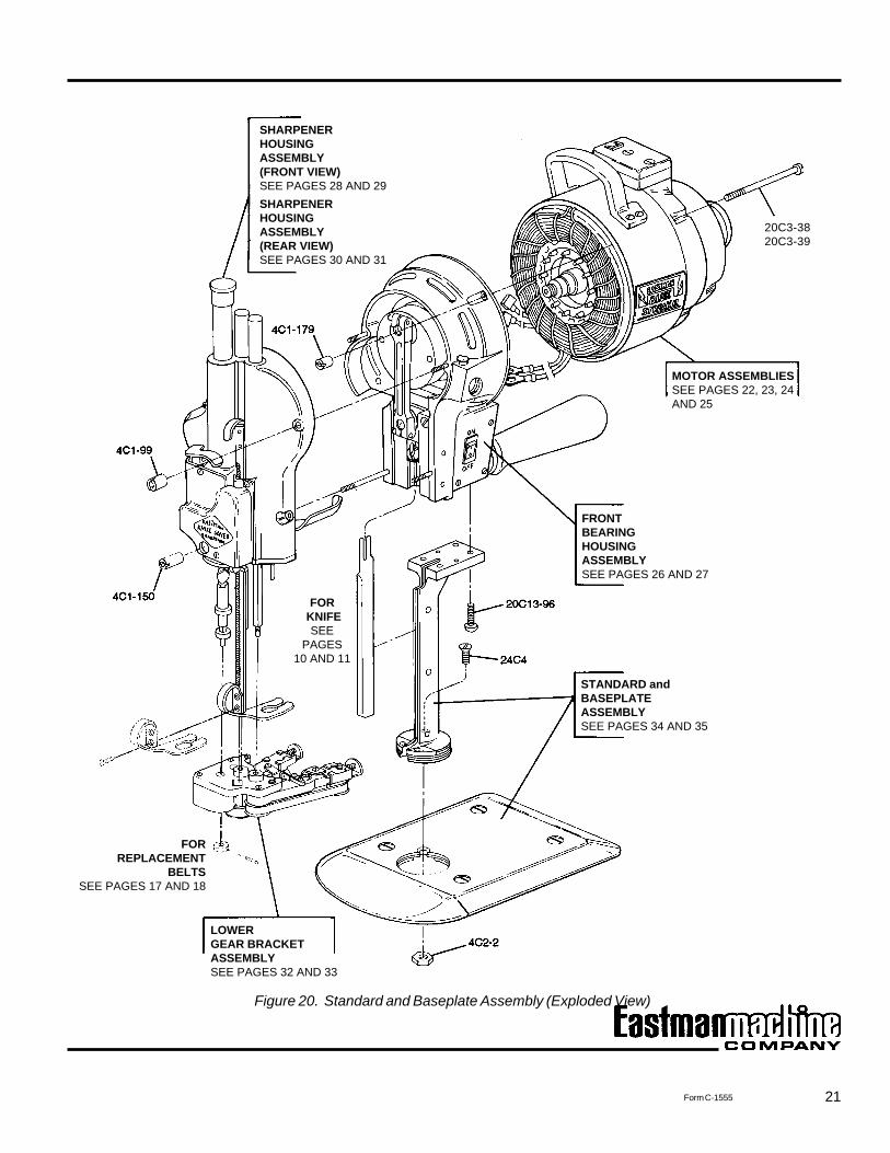
Illustrated Parts List
Your Eastman Straight Knife has been carefully designed toprovide many hours of trouble-free operation. The compre-hensive exploded parts illustrations have been carefully pre-pared to enable you to easily order replacement parts. Re-placement parts for this machine may be ordered throughyour nearest Eastman Machine Company representative ordirectly from the Eastman factory.
Note: Please specify the model and serial number of yourmachine when ordering parts. Always specify class num-ber and serial number when ordering parts for faster, moreefficient service.
Exploded Parts Illustrations
The exploded parts illustrations and parts lists in this sec-tion have been divided into major assemblies as follows:
Motor AssembliesSingle-Phase, Single-Speed Pages 22, 23Single-Phase, Dual-Speed Pages 22, 23Three-Phase, Single-Speed Pages 24, 25Three-Phase, Dual-Speed Pages 24, 25
Front Bearing Housing AssemblySee pages 26 and 27.
Sharpener Housing AssemblyFront view, see pages 28 and 29.Rear view, see pages 30 and 31.
Lower Gear Bracket AssemblySee pages 32 and 33.
Note: Four different abrasive belt grits (designed to provideyou with a selection of edges) may be ordered for this ma-chine. See pages 17 and 18 of this manual for more infor-mation.
Standard and Baseplate AssemblySee pages 34 and 35.
Note: Knife slides and standard heights indicated on pages34 and 35 are based on the length of the knife and do notrefer to physical dimensions. Thus, a 6" knife slide accom-modates a 6" knife. Ordering information and part numbersfor knives may be found on pages 10 and 11.
FASTENERS REQUIRED TO ASSEMBLEMAJOR COMPONENTS
PART NO. NO. REQ'D DESCRIPTION Class Class 627 6294C1-99 3 3 Sharpener Hold-Down Nut4C1-150 1 1 Sharpener Hold-Down Nut4C1-179 4 4 Front-to-Rear Bearing Nut4C2-2 1 1 Plate Bolt Nut20C3-38 0 4 Front-to-Rear Bearing Screw20C3-39 4 0 Front-to-Rear Bearing Screw20C13-96 4 0 Standard-to-Bearing Screw24C4 1 1 Plate Bolt
21Form C-1555
FOR KNIFE
SEEPAGES
10 AND 11
SHARPENERHOUSINGASSEMBLY(FRONT VIEW)SEE PAGES 28 AND 29SHARPENERHOUSINGASSEMBLY(REAR VIEW)SEE PAGES 30 AND 31
STANDARD andBASEPLATEASSEMBLYSEE PAGES 34 AND 35
FORREPLACEMENT
BELTSSEE PAGES 17 AND 18
MOTOR ASSEMBLIESSEE PAGES 22, 23, 24AND 25
FRONTBEARINGHOUSINGASSEMBLYSEE PAGES 26 AND 27
LOWERGEAR BRACKETASSEMBLYSEE PAGES 32 AND 33
20C3-3820C3-39
Figure 20. Standard and Baseplate Assembly (Exploded View)
22
EASTMAN
Form C-1555
Part No. No. Req'd Description
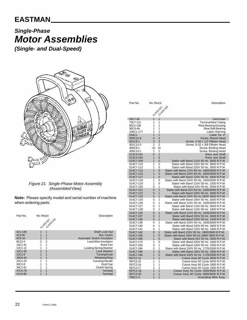
53C7-35 1 1 Fan Cover73C7-121 1 1 Terminal Wire Tubing90C1-146 1 1 Rear Bearing Housing90C6-46 1 1 Rear Ball Bearing236C1-177 1 1 Label, Warning254C1 1 1 Cable Tie, 4"300C12-6 4 4 Screw, Round Head301C8-1 3 3 Screw, 4-40 x 1/2 Fillister Head301C12-3 2 2 Screw, 8-32 x 3/8 Fillister Head305C8-1 10 10 Screw, Binding Head305C10-1 1 1 Screw, Binding Head513C3-241 0 1 Rotor and Shaft513C3-240 1 0 Rotor and Shaft514C7-109 1 0 Stator with Band 110V 60 Hz. 3600 R.P.M.514C7-110 1 0 Stator with Band 220V 60 Hz. 3600 R.P.M.514C7-113 1 0 Stator with Band 220V 50 Hz. 3000 R.P.M.514C7-114 1 0 Stator with Band 110V 60 Hz. 1800/3600 R.P.M.514C7-115 1 0 Stator with Band 220V 60 Hz. 1800/3000 R.P.M.514C7-117 1 0 Stator with Band 110V 50 Hz. 3000 R.P.M.514C7-118 1 0 Stator with Band 220V 50 Hz. 1500/3000 R.P.M.514C7-119 1 0 Stator with Band 110V 50 Hz. 1500 R.P.M.514C7-120 0 1 Stator with Band 42V 50 Hz. 3000 R.P.M.514C7-121 0 1 Stator with Band 42V 50 Hz. 1500/3000 R.P.M.514C7-122 0 1 Stator with Band 100V 60 Hz. 3600 R.P.M.514C7-123 0 1 Stator with Band 100V 60 Hz.1800/ 3600 R.P.M.514C7-124 0 1 Stator with Band 100V 50 Hz. 3000 R.P.M.514C7-126 0 1 Stator with Band 110V 50 Hz. 1500/3000 R.P.M.514C7-127 0 1 Stator with Band 110V 60 Hz. 3600 R.P.M.514C7-128 0 1 Stator with Band 110V 60 Hz. 1800 R.P.M.514C7-129 0 1 Stator with Band 110V 60 Hz. 1500/3000 R.P.M.514C7-137 0 1 Stator with Band 220V 50 Hz. 3000 R.P.M.514C7-138 0 1 Stator with Band 220V 50 Hz. 1500 R.P.M.514C7-139 0 1 Stator with Band 220V 50 Hz. 1500/3000 R.P.M.514C7-140 0 1 Stator with Band 220V 60 Hz. 3600 R.P.M.514C7-141 0 1 Stator with Band 220V 60 Hz. 1800 R.P.M.514C7-142 0 1 Stator with Band 220V 60 Hz. 1800/3600 R.P.M..514C7-156 1 0 Stator with Band 100V 60 Hz.1800/ 3600 R.P.M..514C7-165 1 0 Stator with Band 42V 50 Hz. 3000 R.P.M.514C7-174 1 0 Stator with Band 220V 60 Hz. 1800 R.P.M.514C7-193 0 1 Stator with Band 100V 55 Hz. 3300 R.P.M.514C7-194 0 1 Stator with Band 100V 55 Hz. 1725/3300 R.P.M.514C7-195 1 0 Stator with Band 100V 55 Hz. 3300 R.P.M.514C7-196 1 0 Stator with Band 100V 55 Hz. 1725/3300 R.P.M.597C2-14 1 1 Cutout Assy 60 Cycle 3600 R.P.M.597C2-15 1 1 Cutout Assy 50 Cycle 3000 R.P.M.597C2-16 1 1 Cutout Assy 60 Cycle 1800 R.P.M.597C2-17 1 1 Cutout Assy 50 Cycle 1500 R.P.M.597C2-18 1 1 Cutout Assy 50 Cycle 1500/3000 R.P.M.597C2-25 1 1 Cutout Assy 60 Cycle 1800/3600 R.P.M.783C1-3 1 1 Grounding Wire Assy.
Single-PhaseMotor Assemblies(Single- and Dual-Speed)
Figure 21. Single-Phase Motor Assembly(Assembled View)
Note: Please specify model and serial number of machinewhen ordering parts.
Part No. No. Req'd Description
4C1-145 1 1 Shaft Lock Nut4C2-87 1 1 Nut, Clutch8C5-10 1 1 Automatic Switch Insulation8C12-4 2 2 Lead Wire Insulation10C1-41 1 1 Rotor Fan12C1-12 1 1 Loading Spring Washer12C1-32 1 1 Lock Washer13C1-9 1 1 Turning Knob18C6-16 1 1 Retaining Ring22C1-24 1 1 Carrying Handle30C1-8 1 1 Dust Cap34C1-51 1 1 Clutch Spring47C4-79 1 1 Terminal47C4-80 1 1 Terminal
CLASS 62
7
CLASS 62
9
CLASS 62
7
CLASS 62
9
23Form C-1555
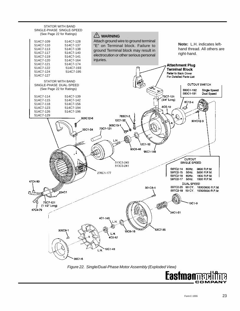
Figure 22. Single/Dual-Phase Motor Assembly (Exploded View)
STATOR WITH BANDSINGLE-PHASE DUAL-SPEED (See Page 22 for Ratings)
514C7-114 514C7-139514C7-115 514C7-142514C7-118 514C7-156514C7-123 514C7-194514C7-126 514C7-196514C7-129
STATOR WITH BANDSINGLE-PHASE SINGLE-SPEED (See Page 22 for Ratings)
514C7-109 514C7-128514C7-110 514C7-137514C7-113 514C7-138514C7-117 514C7-140514C7-119 514C7-141514C7-120 514C7-164514C7-121 514C7-174514C7-122 514C7-193514C7-124 514C7-195514C7-127
Note: L.H. indicates left-hand thread. All others areright-hand.
WARNINGAttach ground wire to ground terminal“E” on Terminal block. Failure toground Terminal block may result inelectrocution or other serious personalinjuries.
24
EASTMAN
Form C-1555
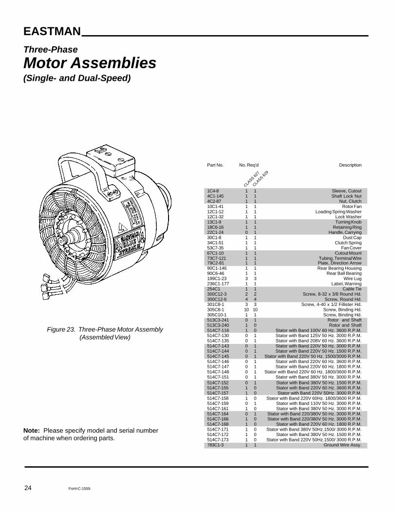
Three-PhaseMotor Assemblies(Single- and Dual-Speed)
Figure 23. Three-Phase Motor Assembly(Assembled View)
Note: Please specify model and serial numberof machine when ordering parts.
Part No. No. Req'd Description
1C4-8 1 1 Sleeve, Cutout4C1-145 1 1 Shaft Lock Nut4C2-87 1 1 Nut, Clutch10C1-41 1 1 Rotor Fan12C1-12 1 1 Loading Spring Washer12C1-32 1 1 Lock Washer13C1-9 1 1 Turning Knob18C6-16 1 1 Retaining Ring22C1-24 0 1 Handle, Carrying30C1-8 1 1 Dust Cap34C1-51 1 1 Clutch Spring53C7-35 1 1 Fan Cover67C1-10 1 1 Cutout Mount73C7-121 1 1 Tubing, Terminal Wire79C2-81 1 1 Plate, Direction Arrow90C1-146 1 1 Rear Bearing Housing90C6-46 1 1 Rear Ball Bearing199C1-23 3 3 Wire Lug236C1-177 1 1 Label, Warning254C1 1 1 Cable Tie300C12-3 2 2 Screw, 8-32 x 3/8 Round Hd.300C12-6 4 4 Screw, Round Hd.301C8-1 3 3 Screw, 4-40 x 1/2 Fillister Hd.305C8-1 10 10 Screw, Binding Hd.305C10-1 1 1 Screw, Binding Hd.513C3-241 0 1 Rotor and Shaft513C3-240 1 0 Rotor and Shaft514C7-116 1 0 Stator with Band 100V 60 Hz. 3600 R.P.M.514C7-130 0 1 Stator with Band 125V 50 Hz. 3000 R.P.M.514C7-135 0 1 Stator with Band 208V 60 Hz. 3600 R.P.M.514C7-143 0 1 Stator with Band 220V 50 Hz. 3000 R.P.M.514C7-144 0 1 Stator with Band 220V 50 Hz. 1500 R.P.M.514C7-145 0 1 Stator with Band 220V 50 Hz. 1500/3000 R.P.M.514C7-146 0 1 Stator with Band 220V 60 Hz. 3600 R.P.M.514C7-147 0 1 Stator with Band 220V 60 Hz. 1800 R.P.M.514C7-148 0 1 Stator with Band 220V 60 Hz. 1800/3600 R.P.M.514C7-151 0 1 Stator with Band 380V 50 Hz. 3000 R.P.M.514C7-152 0 1 Stator with Band 380V 50 Hz. 1500 R.P.M.514C7-155 1 0 Stator with Band 220V 60 Hz. 3600 R.P.M.514C7-157 1 0 Stator with Band 220V 50Hz. 3000 R.P.M.514C7-158 1 0 Stator with Band 220V 60Hz. 1800/3600 R.P.M.514C7-159 0 1 Stator with Band 110V 50 Hz. 3000 R.P.M.514C7-161 1 0 Stator with Band 380V 50 Hz. 3000 R.P.M.514C7-164 0 1 Stator with Band 220/380V 50 Hz. 3000 R.P.M.514C7-166 1 0 Stator with Band 220/380V 50 Hz. 3000 R.P.M.514C7-168 1 0 Stator with Band 220V 60 Hz. 1800 R.P.M.514C7-171 1 0 Stator with Band 380V 50Hz.1500/ 3000 R.P.M.514C7-172 1 0 Stator with Band 380V 50 Hz. 1500 R.P.M.514C7-173 1 0 Stator with Band 220V 50Hz.1500/ 3000 R.P.M.783C1-3 1 1 Ground Wire Assy.
CLASS 62
7
CLASS 62
9
25Form C-1555
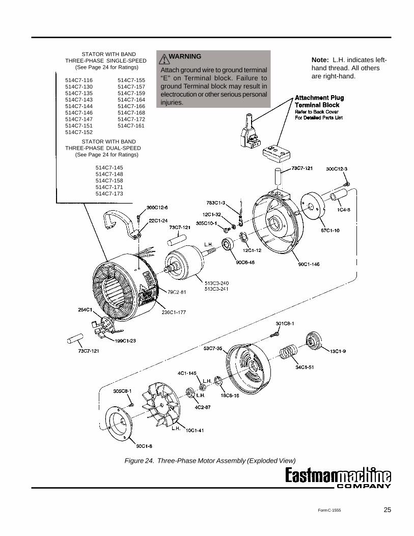
Figure 24. Three-Phase Motor Assembly (Exploded View)
STATOR WITH BANDTHREE-PHASE SINGLE-SPEED (See Page 24 for Ratings)
514C7-116 514C7-155514C7-130 514C7-157514C7-135 514C7-159514C7-143 514C7-164514C7-144 514C7-166514C7-146 514C7-168514C7-147 514C7-172514C7-151 514C7-161514C7-152
STATOR WITH BANDTHREE-PHASE DUAL-SPEED (See Page 24 for Ratings)
514C7-145514C7-148514C7-158514C7-171514C7-173
Note: L.H. indicates left-hand thread. All othersare right-hand.
WARNING
Attach ground wire to ground terminal“E” on Terminal block. Failure toground Terminal block may result inelectrocution or other serious personalinjuries.

26
EASTMAN
Form C-1555
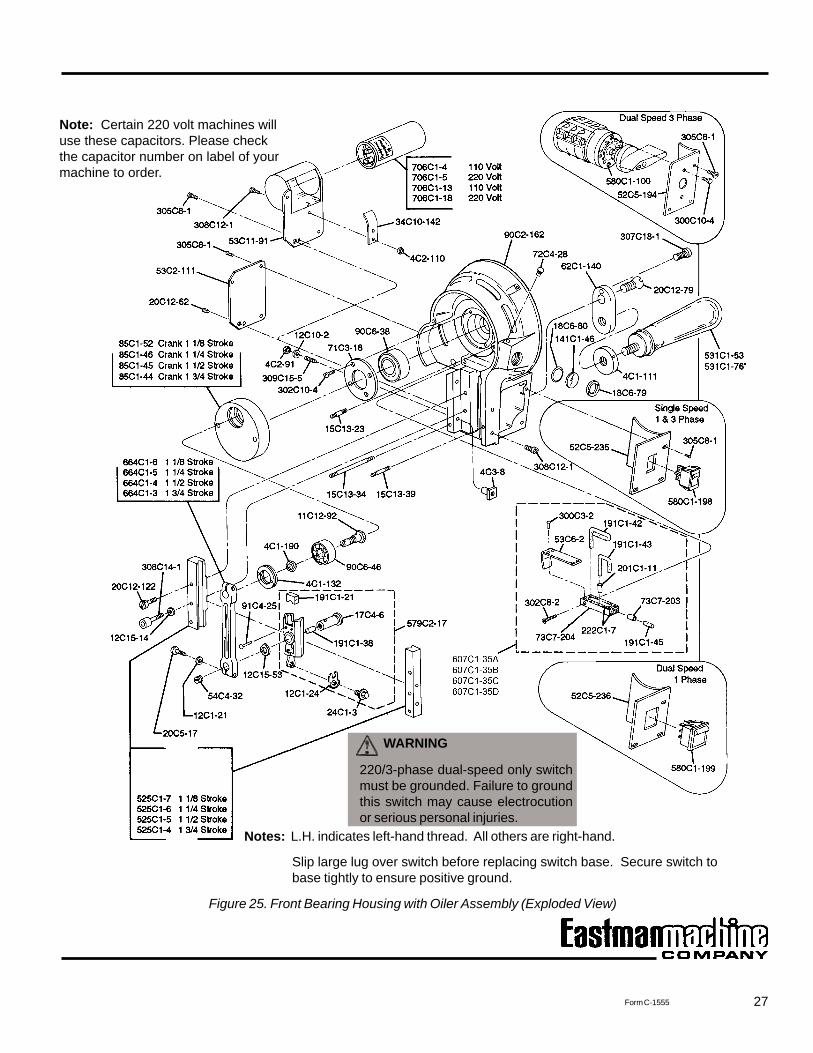
Part No. No. Req'd Description
4C1-111 1 1 Operating Handle Lock Nut4C1-132 1 1 Crank Ball Bearing Lock Nut4C1-190 1 1 Lock Nut for Shaft4C2-91 3 3 Nut for Guide Screw4C2-110 1 1 Stop Nut4C3-8 3 3 Guide Adjustment Nut11C12-92 1 1 Shaft for Ball Bearing12C1-21 2 2 Shakeproof Washer12C1-24 1 1 Knife Lock Washer12C10-2 3 3 Washer12C15-14 6 6 Guide Washer12C15-53 1 1 Connecting Rod Washer15C13-23 2 2 Stud, Upper15C13-34 1 1 Stud, Lower L.H. Mounting15C13-39 1 1 Stud, Lower R.H. Mounting17C4-6 1 1 Wrist Pin18C6-79 1 1 Lock Ring18C6-80 1 1 O-Ring20C5-17 2 2 Connecting Rod Clamp Screw20C12-62 1 1 Front Housing Plug Screw20C12-79 1 1 Screw for Handle Bracket24C1-3 1 1 Knife Lock Bolt34C10-142 1 1 Spring for Capacitor52C5-194 1 1 Switch Plate (Dual-Speed Three-Phase)52C5-235 1 1 Switch Plate (Single-Speed)52C5-236 1 1 Switch Plate (Dual-Speed Single-Phase)53C2-111 1 1 Switch Cover53C6-2 1 1 Oiler Tube Cover53C11-91 1 1 Capacitor Cover54C4-32 1 1 Wrist Pin Plug
Front Bearing Housing(90C2-162) with OilerAssembly
Note: Please specify model and serialnumber of machine when ordering parts.
CLASS 62
7
CLASS 62
9
Part No. No. Req'd Description
62C1-140 1 1 Handle Bracket71C3-18 1 1 Front Ball Bearing Retainer72C4-28 1 1 Oil Hole Cover73C7-203 1 1 Oil Tube, Clear73C7-204 1 1 Oiler Tube85C1-52 1 1 Crank-1-1/8 Stroke85C1-46 1 1 Crank 1-1/4 Stroke85C1-45 1 1 Crank 1-1/2 Stroke85C1-44 1 1 Crank 1-3/4 Stroke90C2-162 1 1 Front Bearing Housing90C6-38 1 1 Front Ball Bearing90C6-46 1 1 Seated Crank Ball Bearing91C4-25 2 2 Rivet Crosshead141C1-46 1 1 Gauge, Clear191C1-21 1 1 Cross Head Felt pad191C1-38 1 1 Wrist Pin Felt Pad191C1-42 1 1 Oil Felt Wicking, Long191C1-43 1 1 Oil Felt Wicking, Short191C1-45 1 1 Oil Felt Wicking, .187 x .44201C1-11 1 1 Eyelet222C1-7 1 1 RTV Sealer300C3-2 4 4 Screw302C8-2 1 1 Screw, Flat Head 4-40 x 3/4300C10-4 2 2 Screw, 6-32 x 3/8 Long Round Head302C10-4 4 4 Screw, 6-32 x 5/16 Flat Head305C8-1 7 7 Screw. 4-40x 1/4 Binding Head307C18-1 1 1 Screw308C12-1 3 3 Screw, 8-32 x 3/8 Socket Head308C14-1 6 6 Guide Hold Down Screw309C15-5 3 3 Guide Adjustment Screw525C1-4 1 1 L.H. & R.H. Guides 1-3/4 Stroke525C1-5 1 1 L.H. & R.H. Guides 1-1/2 Stroke525C1-6 1 1 L.H. & R.H. Guides 1-1/4 Stroke525C1-7 1 1 L.H. & R.H. Guides 1-1/8 Stroke531C1-53 1 1 Operating Handle531C1-76* 1 (ea. machine class) Cushion Grip Handle579C2-17 1 1 Cross Head (With Wrist Pin, Lock Washer & Bolt)580C1-100 1 1 Switch - Dual-Speed 3-Phase580C1-198 1 1 Switch - Single-Speed 1- & 3-Phase580C1-199 1 1 Switch - Dual-Speed 1-Phase607C1-35A 1 1 Oiling Device, 1-1/8" Stroke607C1-35B 1 1 Oiling Device, 1-1/4" Stroke607C1-35C 1 1 Oiling Device, 1-1/2" Stroke607C1-35D 1 1 Oiling Device, 1-3/4" Stroke664C1-6 1 1 Connecting Rod 1-1/8" Stroke664C1-5 1 1 Connecting Rod 1-1/4" Stroke664C1-4 1 1 Connecting Rod 1-1/2" Stroke664C1-3 1 1 Connecting Rod 1-3/4" Stroke706C1-4 0 1 Capacitor 110 Volt706C1-5 0 1 Capacitor 220 Volt706C1-13 1 0 Capacitor 110 Volt706C1-18 1 0 Capacitor 220 Volt
CLASS 62
7
CLASS 62
9
27Form C-1555
Figure 25. Front Bearing Housing with Oiler Assembly (Exploded View)
Note: Certain 220 volt machines willuse these capacitors. Please checkthe capacitor number on label of yourmachine to order.
WARNING
220/3-phase dual-speed only switchmust be grounded. Failure to groundthis switch may cause electrocutionor serious personal injuries.
Notes: L.H. indicates left-hand thread. All others are right-hand.
Slip large lug over switch before replacing switch base. Secure switch tobase tightly to ensure positive ground.
28
EASTMAN
Form C-1555
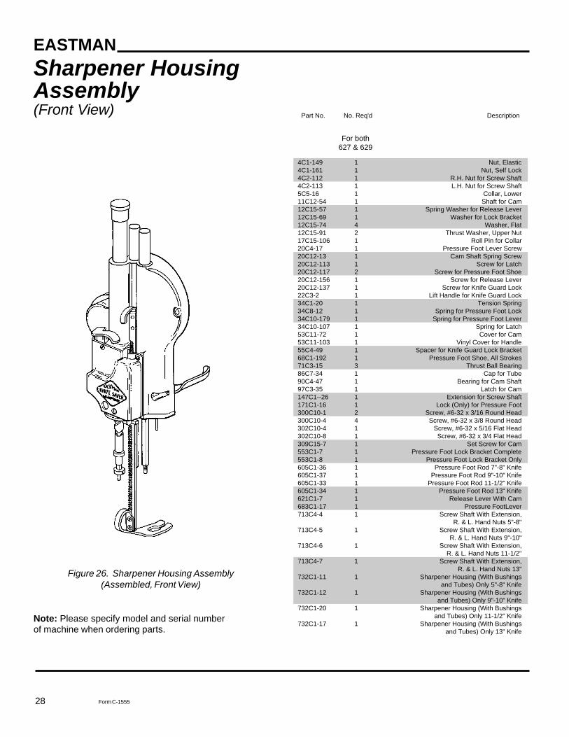
Part No. No. Req'd Description
4C1-149 1 Nut, Elastic4C1-161 1 Nut, Self Lock4C2-112 1 R.H. Nut for Screw Shaft4C2-113 1 L.H. Nut for Screw Shaft5C5-16 1 Collar, Lower11C12-54 1 Shaft for Cam12C15-57 1 Spring Washer for Release Lever12C15-69 1 Washer for Lock Bracket12C15-74 4 Washer, Flat12C15-91 2 Thrust Washer, Upper Nut17C15-106 1 Roll Pin for Collar20C4-17 1 Pressure Foot Lever Screw20C12-13 1 Cam Shaft Spring Screw20C12-113 1 Screw for Latch20C12-117 2 Screw for Pressure Foot Shoe20C12-156 1 Screw for Release Lever20C12-137 1 Screw for Knife Guard Lock22C3-2 1 Lift Handle for Knife Guard Lock34C1-20 1 Tension Spring34C8-12 1 Spring for Pressure Foot Lock34C10-179 1 Spring for Pressure Foot Lever34C10-107 1 Spring for Latch53C11-72 1 Cover for Cam53C11-103 1 Vinyl Cover for Handle55C4-49 1 Spacer for Knife Guard Lock Bracket68C1-192 1 Pressure Foot Shoe, All Strokes71C3-15 3 Thrust Ball Bearing86C7-34 1 Cap for Tube90C4-47 1 Bearing for Cam Shaft97C3-35 1 Latch for Cam147C1--26 1 Extension for Screw Shaft171C1-16 1 Lock (Only) for Pressure Foot300C10-1 2 Screw, #6-32 x 3/16 Round Head300C10-4 4 Screw, #6-32 x 3/8 Round Head302C10-4 1 Screw, #6-32 x 5/16 Flat Head302C10-8 1 Screw, #6-32 x 3/4 Flat Head309C15-7 1 Set Screw for Cam553C1-7 1 Pressure Foot Lock Bracket Complete553C1-8 1 Pressure Foot Lock Bracket Only605C1-36 1 Pressure Foot Rod 7"-8" Knife605C1-37 1 Pressure Foot Rod 9"-10" Knife605C1-33 1 Pressure Foot Rod 11-1/2" Knife605C1-34 1 Pressure Foot Rod 13" Knife621C1-7 1 Release Lever With Cam683C1-17 1 Pressure FootLever713C4-4 1 Screw Shaft With Extension,
R. & L. Hand Nuts 5"-8"713C4-5 1 Screw Shaft With Extension,
R. & L. Hand Nuts 9"-10"713C4-6 1 Screw Shaft With Extension,
R. & L. Hand Nuts 11-1/2"713C4-7 1 Screw Shaft With Extension,
R. & L. Hand Nuts 13"732C1-11 1 Sharpener Housing (With Bushings
and Tubes) Only 5"-8" Knife732C1-12 1 Sharpener Housing (With Bushings
and Tubes) Only 9"-10" Knife732C1-20 1 Sharpener Housing (With Bushings
and Tubes) Only 11-1/2" Knife732C1-17 1 Sharpener Housing (With Bushings
and Tubes) Only 13" Knife
Sharpener HousingAssembly(Front View)
For both627 & 629
Note: Please specify model and serial numberof machine when ordering parts.
Figure 26. Sharpener Housing Assembly(Assembled, Front View)
29Form C-1555
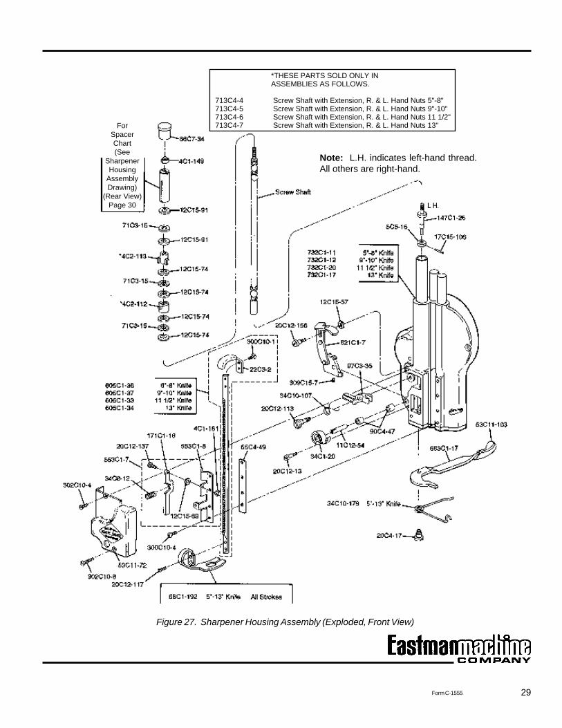
*THESE PARTS SOLD ONLY INASSEMBLIES AS FOLLOWS.
713C4-4 Screw Shaft with Extension, R. & L. Hand Nuts 5"-8" 713C4-5 Screw Shaft with Extension, R. & L. Hand Nuts 9"-10" 713C4-6 Screw Shaft with Extension, R. & L. Hand Nuts 11 1/2" 713C4-7 Screw Shaft with Extension, R. & L. Hand Nuts 13"
Figure 27. Sharpener Housing Assembly (Exploded, Front View)
ForSpacerChart(See
SharpenerHousing
AssemblyDrawing)
(Rear View)Page 30
Note: L.H. indicates left-hand thread.All others are right-hand.
30
EASTMAN
Form C-1555
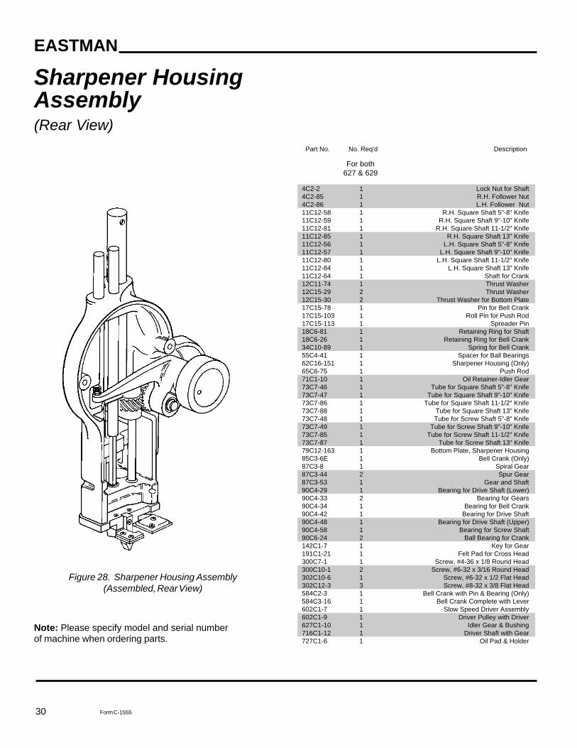
Part No. No. Req'd Description
4C2-2 1 Lock Nut for Shaft4C2-85 1 R.H. Follower Nut4C2-86 1 L.H. Follower Nut11C12-58 1 R.H. Square Shaft 5"-8" Knife11C12-59 1 R.H. Square Shaft 9"-10" Knife11C12-81 1 R.H. Square Shaft 11-1/2" Knife11C12-85 1 R.H. Square Shaft 13" Knife11C12-56 1 L.H. Square Shaft 5"-8" Knife11C12-57 1 L.H. Square Shaft 9"-10" Knife11C12-80 1 L.H. Square Shaft 11-1/2" Knife11C12-84 1 L.H. Square Shaft 13" Knife11C12-64 1 Shaft for Crank12C11-74 1 Thrust Washer12C15-29 2 Thrust Washer12C15-30 2 Thrust Washer for Bottom Plate17C15-78 1 Pin for Bell Crank17C15-103 1 Roll Pin for Push Rod17C15-113 1 Spreader Pin18C6-81 1 Retaining Ring for Shaft18C6-26 1 Retaining Ring for Bell Crank34C10-89 1 Spring for Bell Crank55C4-41 1 Spacer for Ball Bearings62C16-151 1 Sharpener Housing (Only)65C6-75 1 Push Rod71C1-10 1 Oil Retainer-Idler Gear73C7-46 1 Tube for Square Shaft 5"-8" Knife73C7-47 1 Tube for Square Shaft 9"-10" Knife73C7-86 1 Tube for Square Shaft 11-1/2" Knife73C7-88 1 Tube for Square Shaft 13" Knife73C7-48 1 Tube for Screw Shaft 5"-8" Knife73C7-49 1 Tube for Screw Shaft 9"-10" Knife73C7-85 1 Tube for Screw Shaft 11-1/2" Knife73C7-87 1 Tube for Screw Shaft 13" Knife79C12-163 1 Bottom Plate, Sharpener Housing85C3-6E 1 Bell Crank (Only)87C3-8 1 Spiral Gear87C3-44 2 Spur Gear87C3-53 1 Gear and Shaft90C4-29 1 Bearing for Drive Shaft (Lower)90C4-33 2 Bearing for Gears90C4-34 1 Bearing for Bell Crank90C4-42 1 Bearing for Drive Shaft90C4-48 1 Bearing for Drive Shaft (Upper)90C4-58 1 Bearing for Screw Shaft90C6-24 2 Ball Bearing for Crank142C1-7 1 Key for Gear191C1-21 1 Felt Pad for Cross Head300C7-1 1 Screw, #4-36 x 1/8 Round Head300C10-1 2 Screw, #6-32 x 3/16 Round Head302C10-6 1 Screw, #6-32 x 1/2 Flat Head302C12-3 3 Screw, #8-32 x 3/8 Flat Head584C2-3 1 Bell Crank with Pin & Bearing (Only)584C3-16 1 Bell Crank Complete with Lever602C1-7 1 Slow Speed Driver Assembly602C1-9 1 Driver Pulley with Driver627C1-10 1 Idler Gear & Bushing716C1-12 1 Driver Shaft with Gear727C1-6 1 Oil Pad & Holder
For both627 & 629
Sharpener HousingAssembly(Rear View)
Note: Please specify model and serial numberof machine when ordering parts.
Figure 28. Sharpener Housing Assembly(Assembled, Rear View)
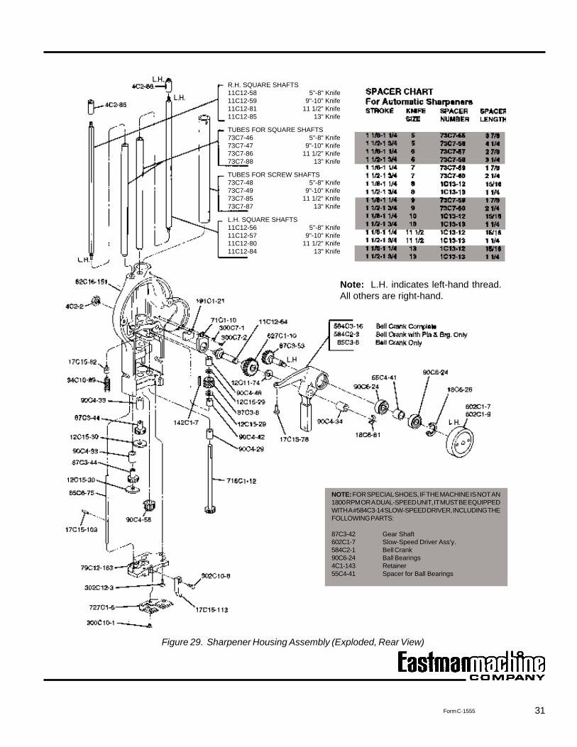
31Form C-1555
Figure 29. Sharpener Housing Assembly (Exploded, Rear View)
Note: L.H. indicates left-hand thread.All others are right-hand.
R.H. SQUARE SHAFTS11C12-58 5"-8" Knife11C12-59 9"-10" Knife11C12-81 11 1/2" Knife11C12-85 13" Knife
TUBES FOR SQUARE SHAFTS73C7-46 5"-8" Knife73C7-47 9"-10" Knife73C7-86 11 1/2" Knife73C7-88 13" Knife
TUBES FOR SCREW SHAFTS73C7-48 5"-8" Knife73C7-49 9"-10" Knife73C7-85 11 1/2" Knife73C7-87 13" Knife
L.H. SQUARE SHAFTS11C12-56 5"-8" Knife11C12-57 9"-10" Knife11C12-80 11 1/2" Knife11C12-84 13" Knife
NOTE: FOR SPECIAL SHOES, IF THE MACHINE IS NOT AN1800 RPM OR A DUAL-SPEED UNIT, IT MUST BE EQUIPPEDWITH A #584C3-14 SLOW-SPEED DRIVER, INCLUDING THEFOLLOWING PARTS:
87C3-42 Gear Shaft602C1-7 Slow-Speed Driver Ass'y.584C2-1 Bell Crank90C6-24 Ball Bearings4C1-143 Retainer55C4-41 Spacer for Ball Bearings
32
EASTMAN
Form C-1555
Note: Please specify model and serial numberof machine when ordering parts.
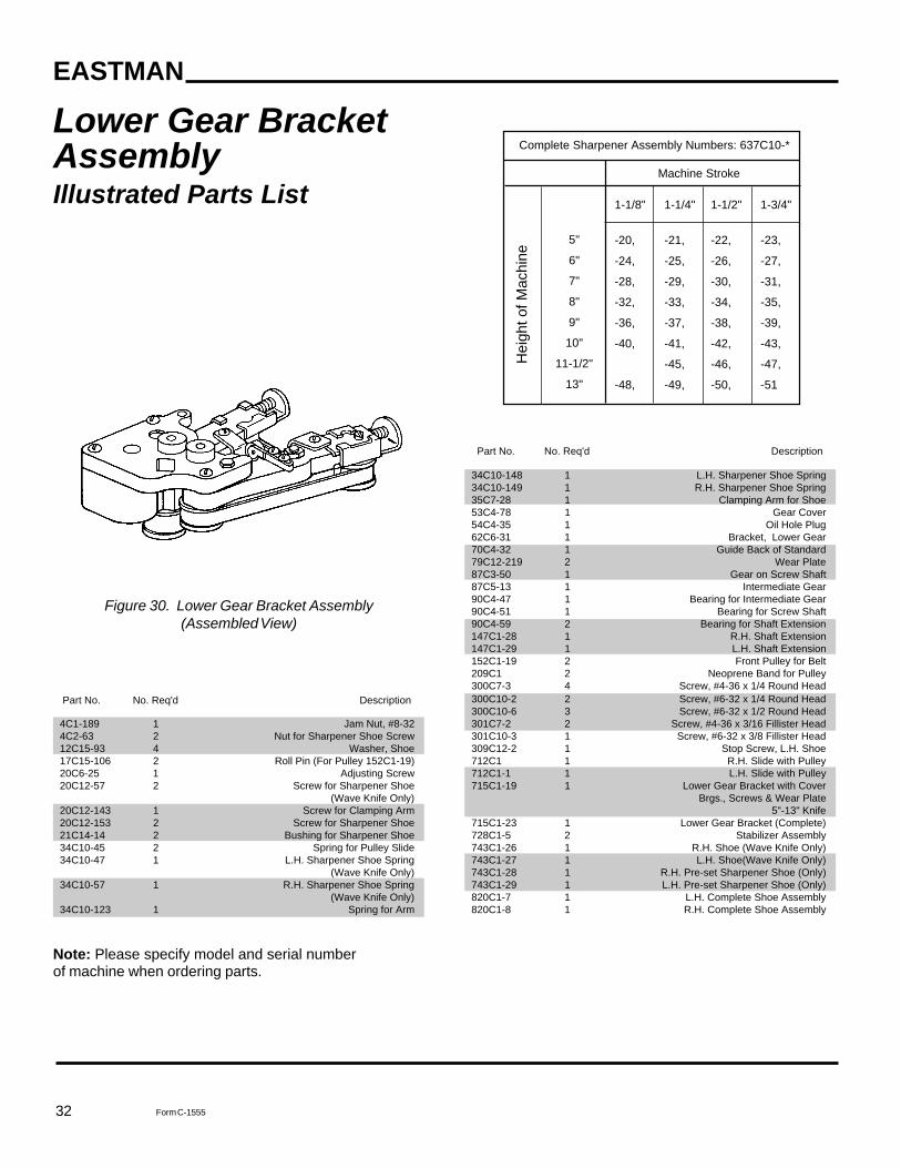
Figure 30. Lower Gear Bracket Assembly(Assembled View)
Lower Gear BracketAssemblyIllustrated Parts List
Complete Sharpener Assembly Numbers: 637C10-*
Machine Stroke
1-1/8" 1-1/4" 1-1/2" 1-3/4"
-20, -21, -22, -23,
-24, -25, -26, -27,
-28, -29, -30, -31,
-32, -33, -34, -35,
-36, -37, -38, -39,
-40, -41, -42, -43,
-45, -46, -47,
-48, -49, -50, -51
5"
6"
7"
8"
9"
10"
11-1/2"
13"
Hei
ght o
f Mac
hine
Part No. No. Req'd Description
4C1-189 1 Jam Nut, #8-324C2-63 2 Nut for Sharpener Shoe Screw12C15-93 4 Washer, Shoe17C15-106 2 Roll Pin (For Pulley 152C1-19)20C6-25 1 Adjusting Screw20C12-57 2 Screw for Sharpener Shoe
(Wave Knife Only)20C12-143 1 Screw for Clamping Arm20C12-153 2 Screw for Sharpener Shoe21C14-14 2 Bushing for Sharpener Shoe34C10-45 2 Spring for Pulley Slide34C10-47 1 L.H. Sharpener Shoe Spring
(Wave Knife Only)34C10-57 1 R.H. Sharpener Shoe Spring
(Wave Knife Only)34C10-123 1 Spring for Arm
Part No. No. Req'd Description
34C10-148 1 L.H. Sharpener Shoe Spring34C10-149 1 R.H. Sharpener Shoe Spring35C7-28 1 Clamping Arm for Shoe53C4-78 1 Gear Cover54C4-35 1 Oil Hole Plug62C6-31 1 Bracket, Lower Gear70C4-32 1 Guide Back of Standard79C12-219 2 Wear Plate87C3-50 1 Gear on Screw Shaft87C5-13 1 Intermediate Gear90C4-47 1 Bearing for Intermediate Gear90C4-51 1 Bearing for Screw Shaft90C4-59 2 Bearing for Shaft Extension147C1-28 1 R.H. Shaft Extension147C1-29 1 L.H. Shaft Extension152C1-19 2 Front Pulley for Belt209C1 2 Neoprene Band for Pulley300C7-3 4 Screw, #4-36 x 1/4 Round Head300C10-2 2 Screw, #6-32 x 1/4 Round Head300C10-6 3 Screw, #6-32 x 1/2 Round Head301C7-2 2 Screw, #4-36 x 3/16 Fillister Head301C10-3 1 Screw, #6-32 x 3/8 Fillister Head309C12-2 1 Stop Screw, L.H. Shoe712C1 1 R.H. Slide with Pulley712C1-1 1 L.H. Slide with Pulley715C1-19 1 Lower Gear Bracket with Cover
Brgs., Screws & Wear Plate5"-13" Knife
715C1-23 1 Lower Gear Bracket (Complete)728C1-5 2 Stabilizer Assembly743C1-26 1 R.H. Shoe (Wave Knife Only)743C1-27 1 L.H. Shoe(Wave Knife Only)743C1-28 1 R.H. Pre-set Sharpener Shoe (Only)743C1-29 1 L.H. Pre-set Sharpener Shoe (Only)820C1-7 1 L.H. Complete Shoe Assembly820C1-8 1 R.H. Complete Shoe Assembly
33Form C-1555
Figure 31. Lower Gear Bracket Assembly (Exploded View)
Note: L.H. indicates left-hand thread.All others are right-hand.
FOR BELT LISTINGSee Page 18
34
EASTMAN
Form C-1555
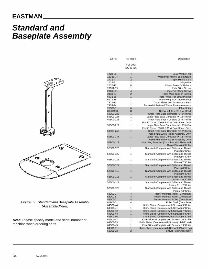
Standard andBaseplate Assembly
Note: Please specify model and serial number ofmachine when ordering parts.
Figure 32. Standard and Baseplate Assembly(Assembled View)
Part No. No. Req'd Description
For both627 & 629
12C1-35 4 Lock Washer, #812C15-77 1 Washer for Micro Fog Standard17C1-4 2 Taper Pin #0 x 3/417C6-9 2 Hinge Pin20C5-12 8 Clamp Screw for Rollers20C12-19 1 Knife Slide Screw20C13-51 4 Hinge Pin Clamp Screw34C1-57 2 Plate Wing Tension Spring60C1-55 1 Plate Wing (For Small Plates)60C1-56 1 Plate Wing (For Large Plates)79C4-12 1 Throat Plates with Screws and Pins79C4-24 1 Tapered & Relieved Throat Plates Assembly213C1-1 6 Fibre Shim302C12-3 3 Screw, #8-32 x 3/8 Flat Head505C3-223 1 Small Plate Base Complete (5"-8" Knife)505C3-224 1 Large Plate Base Complete (9"-13" Knife)505C3-226 1 Small Plate Base Complete (5"-8" Knife)
For 50 Cycle 1500 R.P.M. & Dual-Speed Only505C3-227 1 Large Plate Base Complete (9"-13" Knife)
For 50 Cycle 1500 R.P.M. & Dual-Speed Only505C3-243 1 Small Plate Base Complete (5"-8" Knife)
Used with Swivel Roller Assembly Only505C3-244 1 Large Plate Base Complete (9"-13" Knife)
Used with Swivel Roller Assembly Only528C1-112 1 Micro Fog Standard (Complete with Slides and
Throat Plates) 6" Knife528C1-123 1 Standard (Complete with Slides and Throat
Plates) 5" Knife528C1-120 1 Standard (Complete with Slides and Throat
Plates) 6" Knife528C1-122 1 Standard (Complete with Slides and Throat
Plates) 7" Knife528C1-121 1 Standard (Complete with Slides and Throat
Plates) 8" Knife528C1-115 1 Standard (Complete with Slides and Throat
Plates) 9" Knife528C1-116 1 Standard (Complete with Slides and Throat
Plates) 10" Knife528C1-124 1 Standard (Complete with Slides and Throat
Plates) 11-1/2" Knife528C1-125 1 Standard (Complete with Slides and Throat
Plates) 13" Knife532C2-3 4 Rubber Mounted Roller (Complete)532C2-5 4 Rubber Mounted Roller (Complete)532C2-7 4 Rubber Mounted Roller (Complete)619C1-31 4 Roller Shell (Complete)643C1-44 1 Knife Slides (Complete with Screws) 5" Knife643C1-41 1 Knife Slides (Complete with Screws) 6" Knife643C1-42 1 Knife Slides (Complete with Screws) 7" Knife643C1-43 1 Knife Slides (Complete with Screws) 8" Knife643C1-46 1 Knife Slides (Complete with Screws) 9" Knife643C1-47 1 Knife Slides (Complete with Screws) 10" Knife643C1-53 1 Knife Slides (Complete with Screws) 11-1/2" Knife643C1-45 1 Knife Slides (Complete with Screws) 13" Knife643C1-51 1 Knife Slides (Complete with Screws) 6" Micro Fog619C1-32 2 Swivel Roller Assembly
35Form C-1555
Figure 33. Standard and Baseplate Assembly (Exploded View)
INSTRUCTIONSFOR REMOVING WORNPLATE ROLLER SHELL
Figure 34. Removing a Worn Plate Roller Shell
CAUTION
Do not oil the plate roller shells or you may dam-age them.
Place the plate on blocks and press out theroller shell from the ring assembly (Figure 34).
NOTE: A roller shell (complete with shaft andbearings) may be ordered as required. Specifypart number 619C1-30.
To install a new roller shell, invert the baseplateand press the roller shell into the ring assem-bly.
Form C-1555 © 1988-1990, 1993, 1995, 1996, 1998, 2003, 2007 Eastman Machine Company Printed in U.S.A. 2/07
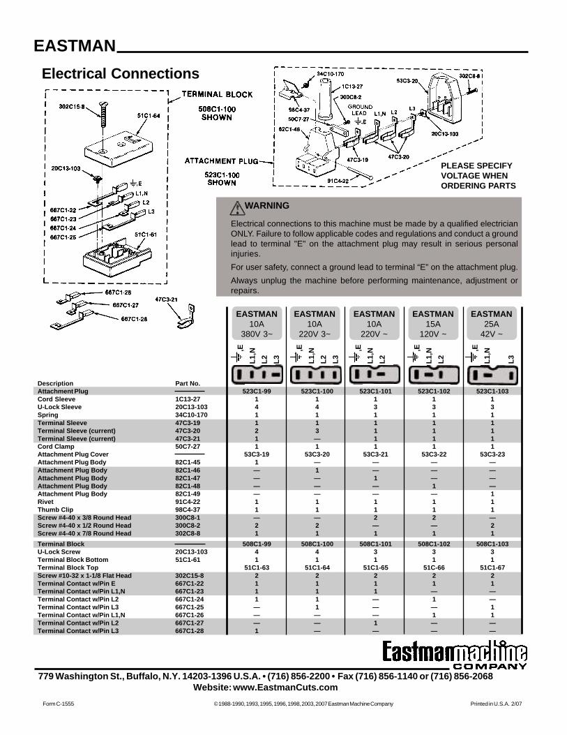
Electrical Connections
PLEASE SPECIFYVOLTAGE WHENORDERING PARTS
Description Part No.Attachment Plug 523C1-99 523C1-100 523C1-101 523C1-102 523C1-103Cord Sleeve 1C13-27 1 1 1 1 1U-Lock Sleeve 20C13-103 4 4 3 3 3Spring 34C10-170 1 1 1 1 1Terminal Sleeve 47C3-19 1 1 1 1 1Terminal Sleeve (current) 47C3-20 2 3 1 1 1Terminal Sleeve (current) 47C3-21 1 — 1 1 1Cord Clamp 50C7-27 1 1 1 1 1Attachment Plug Cover 53C3-19 53C3-20 53C3-21 53C3-22 53C3-23Attachment Plug Body 82C1-45 1 — — — —Attachment Plug Body 82C1-46 — 1 — — —Attachment Plug Body 82C1-47 — — 1 — —Attachment Plug Body 82C1-48 — — — 1 —Attachment Plug Body 82C1-49 — — — — 1Rivet 91C4-22 1 1 1 1 1Thumb Clip 98C4-37 1 1 1 1 1Screw #4-40 x 3/8 Round Head 300C8-1 — — 2 2 —Screw #4-40 x 1/2 Round Head 300C8-2 2 2 — — 2Screw #4-40 x 7/8 Round Head 302C8-8 1 1 1 1 1Terminal Block 508C1-99 508C1-100 508C1-101 508C1-102 508C1-103U-Lock Screw 20C13-103 4 4 3 3 3Terminal Block Bottom 51C1-61 1 1 1 1 1Terminal Block Top 51C1-63 51C1-64 51C1-65 51C-66 51C1-67Screw #10-32 x 1-1/8 Flat Head 302C15-8 2 2 2 2 2Terminal Contact w/Pin E 667C1-22 1 1 1 1 1Terminal Contact w/Pin L1,N 667C1-23 1 1 1 — —Terminal Contact w/Pin L2 667C1-24 1 1 — 1 —Terminal Contact w/Pin L3 667C1-25 — 1 — — 1Terminal Contact w/Pin L1,N 667C1-26 — — — 1 1Terminal Contact w/Pin L2 667C1-27 — — 1 — —Terminal Contact w/Pin L3 667C1-28 1 — — — —
EASTMAN25A
42V ~
EASTMAN15A
120V ~
EASTMAN10A
220V ~
EASTMAN10A
220V 3~
EASTMAN10A
380V 3~
,EL1
,NL2 L3
,E
L1,N
L2 L3
,EL1
,NL2
,E
L1,N
L2
,EL1
,N
L3
WARNING
Electrical connections to this machine must be made by a qualified electricianONLY. Failure to follow applicable codes and regulations and conduct a groundlead to terminal "E" on the attachment plug may result in serious personalinjuries.For user safety, connect a ground lead to terminal “E” on the attachment plug.Always unplug the machine before performing maintenance, adjustment orrepairs.
EASTMAN
779 Washington St., Buffalo, N.Y. 14203-1396 U.S.A. • (716) 856-2200 • Fax (716) 856-1140 or (716) 856-2068Website: www.EastmanCuts.com