easy and safe installation - exelectrics.ru · easy and safe installation “safety plus” : 1-...
TRANSCRIPT

7ATX LUMINAIRES
1
2
3
4
5
Easy and safeinstallation
“Safety Plus” :1- Mounting can be completed with one hand
2- One handed opening using standard tool
3- Reflector swivels easy access
4- Terminal shield cover opens
5- Easy wiring
8
1 23
6
4
5
8
INCREASED SAFETY EEx “e” BI-PIN FLUORESCENT LUMINAIRES
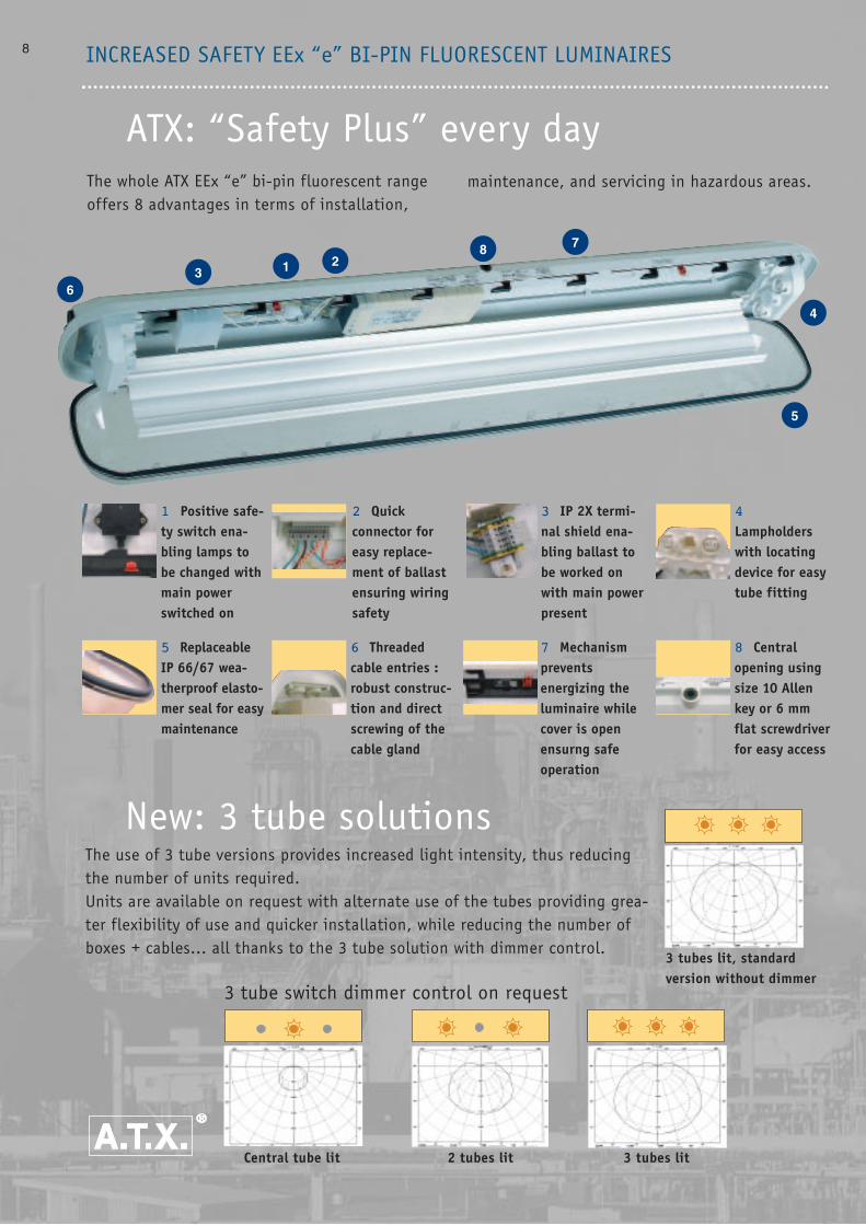
ATX: “Safety Plus” every dayThe whole ATX EEx “e” bi-pin fluorescent rangeoffers 8 advantages in terms of installation,
1 Positive safe-ty switch ena-bling lamps tobe changed withmain powerswitched on
2 Quickconnector foreasy replace-ment of ballastensuring wiringsafety
3 IP 2X termi-nal shield ena-bling ballast tobe worked onwith main powerpresent
4
Lampholderswith locatingdevice for easytube fitting
5 Replaceable IP 66/67 wea-therproof elasto-mer seal for easymaintenance
6 Threadedcable entries :robust construc-tion and directscrewing of thecable gland
7 Mechanismpreventsenergizing theluminaire whilecover is openensurng safeoperation
8 Central opening usingsize 10 Allenkey or 6 mmflat screwdriverfor easy access
New: 3 tube solutionsThe use of 3 tube versions provides increased light intensity, thus reducingthe number of units required.Units are available on request with alternate use of the tubes providing grea-ter flexibility of use and quicker installation, while reducing the number ofboxes + cables... all thanks to the 3 tube solution with dimmer control.
3 tube switch dimmer control on request
Central tube lit 2 tubes lit 3 tubes lit
3 tubes lit, standard version without dimmer
maintenance, and servicing in hazardous areas.
7
9Increased safety lighting
CONTENTS• Equipment for zones 1 and 2 and 21 and 22
Increased safety bi-pin fluorescent luminaires 8
- 110/127 V - 220/240 V non-armoured cable 10
- 110/127 V - 220/240 V armoured cable 12
- 110/127 V - 220/240 V single phase loop in loop out through wiring 14
- 254 V armoured and non-armoured cable 16
Emergency lighting: Normal and emergency bi-pin 18
- 110/127 V - 220/240 V non-armoured cable 20
- 110/127 V - 220/240 V armoured cable 22
- 110/127 V - 220/240 V single phase loop in loop out through wiring 24
- 220/240 V AC and 110 V DC 26
- 230/240 V “self-test” non-armoured cable 28
Mono-pin fluorescent luminaires
- 110/127 V - 220/240 V armoured or non-armoured cable 30
- Normal-emergency 220/240 V armoured or non-armoured cable 32
Level gauge light fitting 110/127 V - 220/240 V non-armoured cable 34
Dimensions of f ixing accessories 36
Installation method for fluorescent luminaires 38
Bi-pin metal-glass fluorescent luminaires
- 220/240 V non-armoured cable 40
- Normal-emergency 220/240V non-armoured cable 42
Intrinsic and increased safety torches dual lens 45
Intrinsic and increased safety torches 2 cell and 3 cell 46
Round bulkhead light non-armoured cable 47
• European Directive and bi-pin fluorescent luminaires 48
• Equipment for zones 2 and 22
110/127 V - 220/240 V bi-pin fluorescent luminaires armoured and non-armoured cable
- “heavy duty” 50
- “light duty” 52
220/240 V normal-emergency fluorescent luminaires
- “heavy duty” 54
- “light duty” 56
Zone 2 and 22 floodlights armoured and non-armoured cable 58
Zone 2 and 22 round bulkhead light armoured and non-armoured cable 59
Zone 2 and 22 wellglass luminaires armoured and non-armoured cable 60
• EGS Group 63
• Spare parts 290
• Certificates 292
• ATX guide 302
10
Part number in bold : fast moving references
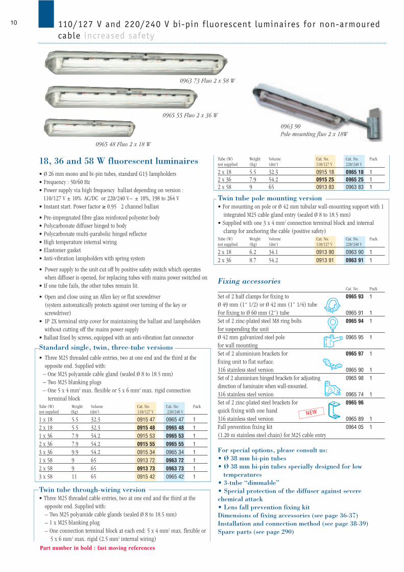
110/127 V and 220/240 V bi-pin f luorescent luminaires for non-armouredcable increased safety
0965 55 Fluo 2 x 36 W
0965 48 Fluo 2 x 18 W
0963 90 Pole-mounting fluo 2 x 18W
Tube (W) Weight Volume Cat. No. Cat. No. Packnot supplied (Kg) (dm3) 110/127 V 220/240 V
2 x 18 5.5 32.3 0915 18 0965 18 12 x 36 7.9 54.2 0915 25 0965 25 12 x 58 9 65 0913 83 0963 83 1
Twin tube pole mounting version • For mounting on pole or Ø 42 mm tubular wall-mounting support with 1
integrated M25 cable gland entry (sealed Ø 8 to 18.5 mm)• Supplied with one 3 x 4 mm2 connection terminal block and internal
clamp for anchoring the cable (positive safety)Tube (W) Weight Volume Cat. No. Cat. No. Packnot supplied (Kg) (dm3) 110/127 V 220/240 V
2 x 18 6.2 34.1 0913 90 0963 90 12 x 36 8.7 54.2 0913 91 0963 91 1
Fixing accessoriesCat. No. Pack
Set of 2 half clamps for fixing to 0965 93 1Ø 49 mm (1“ 1/2) or Ø 42 mm (1” 1/4) tubeFor fixing to Ø 60 mm (2“) tube 0965 91 1Set of 2 zinc-plated steel M8 ring bolts 0965 94 1for suspending the unit Ø 42 mm galvanized steel pole 0965 95 1for wall mountingSet of 2 aluminium brackets for 0965 97 1fixing unit to flat surface.316 stainless steel version 0965 90 1Set of 2 aluminium hinged brackets for adjusting 0965 98 1direction of luminaire when wall-mounted.316 stainless steel version 0965 74 1Set of 2 zinc-plated steel brackets for 0965 96quick fixing with one hand316 stainless steel version 0965 89 1Fall prevention fixing kit 0964 05 1(1.20 m stainless steel chain) for M25 cable entry
For special options, please consult us:• Ø 38 mm bi-pin tubes• Ø 38 mm bi-pin tubes specially designed for low
temperatures• 3-tube “dimmable”• Special protection of the diffuser against severe chemical attack• Lens fall prevention fixing kitDimensions of fixing accessories (see page 36-37) Installation and connection method (see page 38-39)Spare parts (see page 290)
NEW
18, 36 and 58 W fluorescent luminaires• Ø 26 mm mono and bi-pin tubes, standard G13 lampholders• Frequency : 50/60 Hz• Power supply via high frequency ballast depending on version :
110/127 V ± 10% AC/DC or 220/240 V~ ± 10%, 198 to 264 V• Instant start. Power factor ≥ 0.95 2 channel ballast
• Pre-impregnated fibre glass reinforced polyester body• Polycarbonate diffuser hinged to body• Polycarbonate multi-parabolic hinged reflector• High temperature internal wiring• Elastomer gasket• Anti-vibration lampholders with spring system
• Power supply to the unit cut off by positive safety switch which operateswhen diffuser is opened, for replacing tubes with mains power switched on
• If one tube fails, the other tubes remain lit.
• Open and close using an Allen key or flat screwdriver (system automatically protects against over turning of the key or screwdriver)
• IP 2X terminal strip cover for maintaining the ballast and lampholderswithout cutting off the mains power supply
• Ballast fixed by screws, equipped with an anti-vibration fast connector
Standard single, twin, three-tube versions• Three M25 threaded cable entries, two at one end and the third at the
opposite end. Supplied with:– One M25 polyamide cable gland (sealed Ø 8 to 18.5 mm)– Two M25 blanking plugs– One 5 x 4 mm2 max. flexible or 5 x 6 mm2 max. rigid connection
terminal blockTube (W) Weight Volume Cat. No. Cat. No. Packnot supplied (Kg) (dm3) 110/127 V 220/240 V
1 x 18 5.5 32.3 0915 47 0965 47 12 x 18 5.5 32.3 0915 48 0965 48 11 x 36 7.9 54.2 0915 53 0965 53 12 x 36 7.9 54.2 0915 55 0965 55 13 x 36 9.9 54.2 0915 34 0965 34 11 x 58 9 65 0913 72 0963 72 12 x 58 9 65 0913 73 0963 73 1 3 x 58 11 65 0915 42 0965 42 1
Twin tube through-wiring version • Three M25 threaded cable entries, two at one end and the third at the
opposite end. Supplied with:– Two M25 polyamide cable glands (sealed Ø 8 to 18.5 mm)– 1 x M25 blanking plug– One connection terminal block at each end: 5 x 4 mm2 max. flexible or
5 x 6 mm2 max. rigid (2.5 mm2 internal wiring)
0963 73 Fluo 2 x 58 W
11
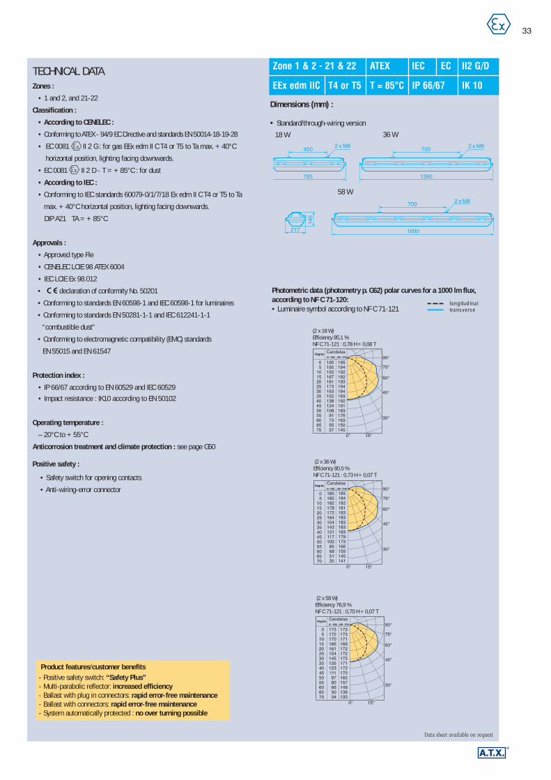
TECHNICAL DATAZones :
• 1 and 2 and 21-22
Classification :
• According to CENELEC:
– Conforming to ATEX - 94/9 EC Directive and standards EN 50014-18-19
– EC 0081 II 2 G for gas EEx ed II C T4 or T5 to Ta max. + 40° C
horizontal position, lighting facing downwards.
– EC 0081 II 2 D T = + 85° C : for dust
• According to IEC:
– Conforming to IEC standards 60079-0/1/7 Ex eds II C T4 or T5 to Ta max.
40°C horizontal position, lighting facing downwards.
DIP A21 TA = + 85° C
Approvals :
• Approved type FLe
• CENELEC LCIE 98 ATEX 6004
• IEC LCIE Ex 98.012
• declaration of conformity No. 50201
• Conforming to standards EN 60598-1 and IEC 60598-1 for luminaires
• Conforming to standards EN 50281-1-1 and IEC 61241-1-1
“combustible dust”
• Conforming to electromagnetic compatibility (EMC) standards
- EN 55015 - EN 61547
Protection index :
• IP 66/67 according to EN 60529 and IEC 60529
• Mechanical resistance: IK10 according to EN 50102
Operating temperature :
- 20° C to + 55° C
Anticorrosion treatment and climate protection : see page G50
Positive safety :
• Safety switch for opening luminaire, see glossary
• Anti-wiring-error connector
“Dimmable” 3-tube operation :
• Alternate use possible (1, 2 or 3 tubes) controlled
by a double switch, available on request
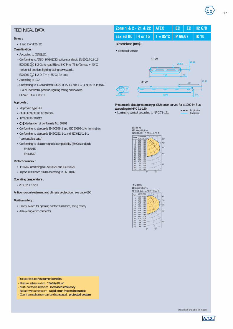
400 700
700
217
785 1390
1690
2 x M8 2 x M8
2 x M8
145
258,5
50
217
145
785
1390
Ø 42
411
50
Ø 42
• Pole-mounting version
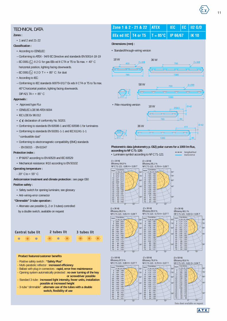
Photometric data (photometry p. G62) polar curves for a 1000 lm flux,according to NF C 71-120:• Luminaire symbol according to NF C 71-121
(1 x 18 W)Efficiency 94,8 %NF C 71-121 : 0,86 H + 0,09 T
(2 x 18 W)Efficiency 85,1 %NF C 71-121 : 0,78 H + 0,08 T
longitudinaltransverse
(1 x 36 W)Efficiency 89,3 %NF C 71-121 : 0,81 H + 0,08 T
(2 x 36 W)Efficiency 80,5 %NF C 71-121 : 0,73 H + 0,07 T
(3 x 36 W)Efficiency 68,1 %NF C 71-121 : 0,63 G + 0,05 T
(1 x 58 W)Efficiency 87,5 %NF C 71-121 : 0,80 H + 0,07 T
(2 x 58 W)Efficiency 76,9 %NF C 71-121 : 0,70 H + 0,07 T
(3 x 58 W)Efficiency 65,6 %NF C 71-121 : 0,61 G + 0,04 T
Dimensions (mm) :
• Standard/through-wiring version
Product features/customer benefits
- Positive safety switch : “Safety Plus”- Multi-parabolic reflector : increased efficiency- Ballast with plug in connectors : rapid, error-free maintenance- Opening system automatically protected : no over turning of the key
or screwdriver possible- Standard 3-tube : increased light intensity, fewer units, installation
possible at increased height- 3-tube “dimmable” : alternate use of the tubes with a double
switch, flexibility of use
Data sheet available on request
Zone 1 & 2 - 21 & 22 ATEX IEC EC II2 G/D
EEx ed IIC T4 or T5 T = 85°C IP 66/67 IK 10
18 W 36 W
36 W
58 W
18 W
Central tube lit 3 tubes lit 2 tubes lit

12
Part number in bold : fast moving references
110/127 V and 220/240 V bi-pin f luorescent luminaires for armouredcable increased safety
0965 45 Fluo 2 x 36 W
NEW
18, 36 and 58 W fluorescent luminaires• Ø 26 mm bi-pin tubes, standard G 13 lampholders• Frequency: 50/60 Hz• Power supply via high frequency ballast depending on version :
110/127 V ± 10% AC/DC or 220/240 V~ ± 10%, 198 to 264 V• Instant start. Power factor ≥ 0.95 2 channel ballast
• Pre-impregnated fibre glass reinforced polyester body• Polycarbonate diffuser hinged to body• Polycarbonate multi-parabolic hinged reflector• High temperature internal wiring• Elastomer gasket• Anti-vibration lampholders with spring system
• Power supply to the unit cut off by positive safety switch which operateswhen diffuser is opened, for replacing tubes with mains power switched on
• If one tube fails, the other tubes remain lit.
• Open and close using an Allen key or flat screwdriver (system automatically protects against over turning)
• IP 2X terminal strip cover for maintaining the ballast and lampholderswithout cutting off the mains power supply
• Ballast fixed by screws, equipped with an anti-vibration fast connector
Standard single, twin, three-tube version• Two M20 threaded cable entries with earth continuity plate for
armoured cables at one end (cable gland not supplied)• One clearance hole for M20 cable gland at the opposite end• Supplied with:
– Two M20 blanking plugs and one M20 locknut– One 5 x 4 mm2 max. flexible or 5 x 6 mm2 max. rigid connection ter-minal block
Tube (W) Weight Volume Cat. No. Cat. No. Packnot supplied (Kg) (dm3) 110/127 V 220/240 V
1 x 18 5.5 32.3 0915 35 0965 35 12 x 18 5.5 32.3 0915 38 0965 38 11 x 36 7.9 54.2 0915 43 0965 43 12 x 36 7.9 54.2 0915 45 0965 45 13 x 36 9.9 54.2 0915 39 0965 39 11 x 58 9 65 0913 42 0963 42 12 x 58 9 65 0913 43 0963 43 13 x 58 11 65 0915 49 0965 49 1
Through-wiring version with possibility of phasebalancing• Three M20 threaded cable entries with earth continuity plate for armoured
cables, 2 cable entries at one end, and the third at the opposite end (cablegland not supplied)
• Supplied with:– 1 x M20 blanking plug– One 5 x 4 mm2 max. flexible or 5 x 6 mm2 max. rigid (2.5 mm2
internal wiring) connection terminal block at each endTube (W) Weight Volume Cat. No. Cat. No. Packnot supplied (Kg) (dm3) 110/127 V 220/240 V
2 x 18 5.5 32.3 0913 50 0963 50 12 x 36 7.9 54.2 0915 15 0965 15 12 x 58 9 65 0913 53 0963 53 1
Fixing accessoriesCat. No. Pack
Set of 2 half clamps for fixing to 0965 93 1Ø 49 mm (1“ 1/2) or Ø 42 mm (1” 1/4) tube For fixing to Ø 60 mm (2“) tube: 0965 91 1Set of 2 zinc-plated steel M8 ring bolts 0965 94 1for suspending the unit Set of 2 aluminium brackets for 0965 97 1fixing unit to flat surface. 316 stainless steel version 0965 90 1Set of 2 aluminium hinged brackets for adjusting 0965 98 1direction of luminaire when wall-mounted.316 stainless steel version 0965 74 1Set of 2 zinc-plated brackets for 0965 96 1quick fixing with one hand316 stainless steel version 0965 89 1Fall prevention fixing kit 0964 06 1(1.20 m stainless steel chain) for M20 cable entry
For special options, please consult us:• Ø 38 mm bi-pin tubes• Ø 38 mm bi-pin tubes specially designed for low
temperatures• 3-tube “dimmable”• Special protection of the diffuser against severe
chemical attack• Lens fall prevention fixing kitDimensions of fixing accessories (see page 36-37) Installation and connection method (see page 38-39)Spare parts (see page 290)Cable glands for armoured cable (see pages 252-262)
0965 38 Fluo 2 x 18 W
0963 43 Fluo 2 x 58 W

13
TECHNICAL DATA
Zones :
• 1 and 2 and 21-22
Classification :
• According to CENELEC:
– Conforming to ATEX - 94/9 EC Directive and standards EN 50014-18-19
– EC 0081 II 2 G for gas EEx ed II C T4 or T5 to Ta max. + 40° C
horizontal position, lighting facing downwards
– EC 0081 II 2 D T = + 85°C: for dust
• According to IEC:
– Conforming to IEC standards 60079-0/1/7 Ex eds II C T4 or T5 to Ta max.
+ 40° C horizontal position, lighting facing downwards.
DIP A21 TA = + 85° C
Approvals :
• Approved type FLe
• CENELEC LCIE 98 ATEX 6004
• IEC LCIE Ex 98.012
• declaration of conformity No. 50201
• Conforming to standards EN 60598-1 and IEC 60598-1 for luminaires
• Conforming to standards EN 50281-1-1 and IEC 61241-1-1
“combustible dust”
• Conforming to electromagnetic compatibility (EMC) standards
- EN 55015
- EN 61547
Protection index :
• IP 66/67 according to EN 60529 and IEC 60529
• Mechanical resistance: IK10 according to EN 50102
Operating temperature :
- 20° C to + 55° C
Anticorrosion treatment and climate protection : see page G50
Positive safety :
• Safety switch for opening luminaire, see glossary
• Anti-wiring-error connector
“Dimmable” 3-tube operation :• Alternate use possible (1, 2 or 3 tubes) controlled by a double
switch, available on request
Data sheet available on request
Zone 1 & 2 - 21 & 22 ATEX IEC EC II2 G/D
EEx ed IIC T4 or T5 T = 85°C IP 66/67 IK 10
400 700
700
217
785 1390
1690
2 x M8 2 x M8
2 x M8
145
Photometric data (photometry p. G62) polar curves for a 1000 lm flux,according to NF C 71-120 :• Luminaire symbol according to NF C 71-121
longitudinaltransverse
Dimensions (mm) :
• Standard/through-wiring version
18 W 36 W
58 W
(1 x 18 W)Efficiency 94,8 %NF C 71-121 : 0,86 H + 0,09 T
(2 x 18 W)Efficiency 85,1 %NF C 71-121 : 0,78 H + 0,08 T
(1 x 36 W)Efficiency 89,3 %NF C 71-121 : 0,81 H + 0,08 T
(2 x 36 W)Efficiency 80,5 %NF C 71-121 : 0,73 H + 0,07 T
(3 x 36 W)Efficiency 68,1 %NF C 71-121 : 0,63 G + 0,05 T
(1 x 58 W)Efficiency 87,5 %NF C 71-121 : 0,80 H + 0,07 T
(2 x 58 W)Efficiency 76,9 %NF C 71-121 : 0,70 H + 0,07 T
(3 x 58 W)Efficiency 65,6 %NF C 71-121 : 0,61 G + 0,04 T
Product features/customer benefits
- Positive safety switch : “Safety Plus”- Multi-parabolic reflector : increased efficiency- Ballast with plug in connectors : rapid, error-free maintenance- Opening system automatically protected : no over turning possible- Standard 3-tube : increased light intensity, fewer units, installation
possible at increased height- 3-tube “dimmable” : alternate use of the tubes with a double
switch, flexibility of use
Central tube lit 3 tubes lit 2 tubes lit

Fixing accessoriesCat. No. Pack
Set of 2 half clamps for fixing to 0965 93 1Ø 49 mm (1” 1/2) or Ø 42 mm (1” 1/4) tubeFor fixing to Ø 60 mm (2”) tube 0965 91 1Set of 2 zinc-plated steel M8 ring bolts 0965 94 1for suspending the unit Set of 2 aluminium brackets for fixing 0965 97 1unit to flat surface. 316 stainless steel version 0965 90 1Set of 2 aluminium hinged brackets for adjusting 0965 98 1direction of luminaire when wall-mounted.316 stainless steel version 0965 74 1Set of 2 zinc-plated steel brackets for 0965 96 1quick fixing with one hand316 stainless steel version 0965 89 1Fall prevention fixing kit 0964 06 1(1.20 m stainless steel chain) for M20 cable entry
For special options, please consult us:• Ø 38 mm bi-pin tubes• Ø 38 mm bi-pin tubes specially designed for low
temperatures• 3-tube “dimmable”• Special protection of the diffuser against severe
chemical attack• Lens fall prevention fixing kitDimensions of fixing accessories (see page 36-37) Installation and connection method (see page 38,39)Spare parts (see page 290)Cable glands for armoured cable (see pages 252-262)
14
Part number in bold : fast moving references
110/127 V or 220/240 V bi-pin single phase loop in loop out connection andthrough wiring f luorescent luminaires for armoured cable increased safety
NEW
18, 36 and 58 W fluorescent luminaires• Ø 26 mm bi-pin tubes, standard G 13 lampholders• Designed for single phase mains supplies with a choice of possible instal-
lation methods: terminal position loop in loop out connection andthrough wiring
• Frequency: 50/60 Hz• Power supply via high frequency ballast depending on version :110/127 V ± 10% AC/DC or 220/240 V~ ± 10%, 198 to 264 V• Instant start. Power factor ≥ 0.95 2 channel ballast
• Pre-impregnated fibre glass reinforced polyester body• Polycarbonate diffuser hinged to body• Polycarbonate multi-parabolic hinged reflector• High temperature internal wiring• Elastomer gasket• Anti-vibration lampholders with spring system
• Power supply to the unit cut off by positive safety switch which operateswhen diffuser is opened, for replacing tubes with mains power switchedon
• If one tube fails, the other tube remains lit.
• Open and close using an Allen key or flat screwdriver (system automatically protects against over turning)
• IP 2X terminal strip cover for maintaining the ballast and lampholderswithout cutting off the mains power supply
• Ballast fixed by screws, equipped with a fast connector• Three M20 threaded cable entries with earthing plates for armoured cable
(cable gland not supplied) • Supplied with:
– Two M20 blanking plugs– One connection terminal block at each end
4 x 4mm2 flexible or 4 x 6mm2 rigid max., including 1 earth terminal
Single phase dual loop in loop out connection/throughwiring versionTube (W) Weight Volume Cat. No. Cat. No. Packnot supplied (Kg) (dm3) 110/127 V 220/240 V
2 x 18 5.5 32.3 0913 07 0963 07 12 x 36 7.9 54.2 0913 08 0963 08 12 x 58 9 65 0913 09 0963 09 1
0963 09 Fluo 2 x 58 W
0963 08 Fluo 2 x 36 W
0963 07 Fluo 2 x 18 W

15
TECHNICAL DATA
Zones :
• 1 and 2 and 21-22
Classification :• According to CENELEC:
– Conforming to ATEX - 94/9 EC Directive and standards EN 50014-18-19
– EC 0081 II 2 G: for gas EEx ed II C T4 or T5 to Ta max. + 40° C
horizontal position, lighting facing downwards.
– EC 0081 II 2 D T = +85° C for dust
• According to IEC:
– Conforming to IEC standards 60079-0/1/7 Ex eds II C T4 or T5 to Ta max.
40°C horizontal position, lighting facing downwards.
DIP A21 TA = + 85° C
Approvals :
• Approved type FLe
• CENELEC LCIE 98 ATEX 6004
• IEC LCIE Ex 98.012
• declaration of conformity No. 50201
• Conforming to standards EN 60598-1 and IEC 60598-1 for luminaires
• Conforming to standards EN 50281-1-1 and IEC 61241-1-1
“combustible dust”
• Conforming to electromagnetic compatibility (EMC) standards
- EN 55015
- EN 61547
Protection index :
• IP 66/67 according to EN 60529 and IEC 60529
• Impact resistance: IK10 according to EN 50102
Operating temperature :
- 20° C to + 55° C
Anticorrosion treatment and climate protection : see page G50
Positive safety :
• Safety switch for opening luminaire, see glossary
• Anti-wiring-error connector
Data sheet available on request
Zone 1 & 2 - 21 & 22 ATEX IEC EC II2 G/D
EEx ed IIC T4 or T5 T = 85°C IP 66/67 IK 10
Product features/customer benefits- Positive safety switch : “Safety Plus”- Multi-parabolic reflector : increased efficiency- Ballast with plug in connectors : rapid error-free maintenance- Opening system automatically protected : no over turning possible
Dimensions (mm) :
• Single phase loop in loop out connection/through wiring version
Photometric data (photometry p. G62) polar curves for a 1000 lm flux,according to NF C 71-120 :• Luminaire symbol according to NF C 71-121
longitudinaltransverse
400 700
700
217
785 1390
1690
2 x M8 2 x M8
2 x M8
145
36 W
58 W
18 W
(2 x 18 W)Efficiency 85,1 %NF C 71-121 : 0,78 H + 0,08 T
(2 x 36 W)Efficiency 80,5 %NF C 71-121 : 0,73 H + 0,07 T
(2 x 58 W)Efficiency 76,9 %NF C 71-121 : 0,70 H + 0,07 T

16
Part number in bold : fast moving references
Fixing accessoriesCat. No. Pack
Set of 2 half clamps for fixing under 0965 93 1Ø 49 mm (1” 1/2) or Ø 42 mm (1” 1/4) tubeFor fixing under Ø 60 mm (2”) tube 0965 91 1Set of 2 zinc-plated steel M8 ring bolts 0965 94 1for suspending the unit Set of 2 aluminium brackets for fixing 0965 97 1unit to flat surface. 316 stainless steel version 0965 90 1Set of 2 aluminium hinged brackets for adjusting 0965 98 1direction of luminaire when wall-mounted.316 stainless steel version 0965 74 1Set of 2 zinc-plated brackets for 0965 96 1quick fixing with one hand316 stainless steel version 0965 89 1Fall prevention fixing kit 0964 06 1(1.20 m stainless steel chain) for M20 cable entryFall prevention fixing sling 0964 05 1(1.20 m stainless steel chain) for M25 cable entry
For special options, please consult us:• Single tube• Fa6 tube• Pole mounting version• Special protection of the diffuser against severe
chemical attack • Lens fall prevention fixing kitDimensions of fixing accessories (see page 36-37) Installation and connection method (see page 38-39)Spare parts (see page 290)Cable glands for armoured cable (see pages 252-262)
254 V bi-pin f luorescent luminaires for armoured or non-armoured cableincreased safety
0963 64 Fluo 2 x 36 W
0963 63 Fluo 2 x 18 W
NEW
18 and 36 W fluorescent luminaires• Ø 26 mm bi-pin tubes, standard G 13 lampholders• Frequency: 50/60 Hz• Power supply via high frequency electronic ballast 254 V + 6% - 10%,
229 to 269 V• Instant start. Power factor ≥ 0.95 2 channel ballast
• Pre-impregnated fibre glass reinforced polyester body• Polycarbonate diffuser hinged to body• Polycarbonate multi-parabolic hinged reflector• High temperature internal wiring• Elastomer gasket• Anti-vibration lampholders with spring system
• Power supply to the unit cut off by positive safety switch which operateswhen diffuser is opened, for replacing tubes with mains power switchedon
• If one tube fails, the other tube remains lit.
• Open and close using an Allen key or flat screwdriver (system can be dis-engaged at end of travel)
• IP 2X terminal strip cover for maintaining the ballast and lampholderswithout cutting off the mains power supply
• Ballast fixed by screws, equipped with a fast connector
Standard twin version for non-armoured cable• Three threaded cable entries, 2 at one end and the third at the opposite
end for M25 cable gland.• Supplied with:– One M25 polyamide cable gland (sealed Ø 8 to 18.5 mm) – Two M25 blanking plugs – One 5 x 4 mm2 max. flexible or 5 x 6 mm2 max. rigid connection termi-
nal blockTube (W) Weight Volume Cat. No. Packnot supplied (Kg) (dm3) 254V
2 x 18 5.5 32.3 0963 63 12 x 36 7.9 54.2 0963 64 1
Standard twin version for armoured cable• Two M20 threaded cable entries with earthing plate for armoured cable at
one end (cable gland not supplied) • One clearence hole for M20 cable gland at the opposite end • Supplied with– Two M20 blanking plugs and one M20 locknut – One 5 x 4 mm2 max. flexible or 5 x 6 mm2 max. rigid connection termi-
nal blockTube (W) Weight Volume Cat. No. Packnot supplied (Kg) (dm3) 254V
2 x 18 5.5 32.3 0963 74 12 x 36 7.9 54.2 0963 75 1
TECHNICAL DATA
Zones :
• 1 and 2 and 21-22
Classification :
• According to CENELEC :
– Conforming to ATEX - 94/9 EC Directive standards EN 50014-18-19
– EC 0081 II 2 G : for gas EEx ed II C T4 or T5 to Ta max. + 40°C
horizontal position, lighting facing downwards.
– EC 0081 II 2 D T = + 85°C : for dust
• According to IEC :
– Conforming to IEC standards 60079-0/1/7 Ex eds II C T4 or T5 to Ta max.
+ 40°C horizontal position, lighting facing downwards
DIP A21 TA = + 85°C
Approvals :
• Approved type FLe
• CENELEC LCIE 98 ATEX 6004
• IEC LCIE Ex 98.012
• declaration of conformity No. 50201
• Conforming to standards EN 60598-1 and IEC 60598-1 for luminaires
• Conforming to standards EN 50281-1-1 and IEC 61241-1-1
“combustible dust”
• Conforming to electromagnetic compatibility (EMC) standards
- EN 55015
- EN 61547
Protection index :
• IP 66/67 according to EN 60529 and IEC 60529
• Impact resistance : IK10 according to EN 50102
Operating temperature :
- 20°C to + 55°C
Anticorrosion treatment and climate protection : see page G50
Positive safety :
• Safety switch for opening contact luminaire, see glossary
• Anti-wiring-error connector
17
Data sheet available on request
Zone 1 & 2 - 21 & 22 ATEX IEC EC II2 G/D
EEx ed IIC T4 or T5 T = 85°C IP 66/67 IK 10
Product features/customer benefits- Positive safety switch : “Safety Plus”- Multi-parabolic reflector : increased efficiency- Ballast with connectors : rapid error-free maintenance- Opening mechanism can be disengaged : protected system
Dimensions (mm) :
• Standard version
Photometric data (photometry p. G62) polar curves for a 1000 lm flux,according to NF C 71-120:• Luminaire symbol according to NF C 71-121
longitudinaltransverse
258,5
50
217
145
785
1390
Ø 42
411
50
Ø 42
18 W
36 W
(2 x 18 W)Efficiency 85,1 %NF C 71-121 : 0,78 H + 0,08 T
(2 x 36 W)Efficiency 80,5 %NF C 71-121 : 0,73 H + 0,07 T
18
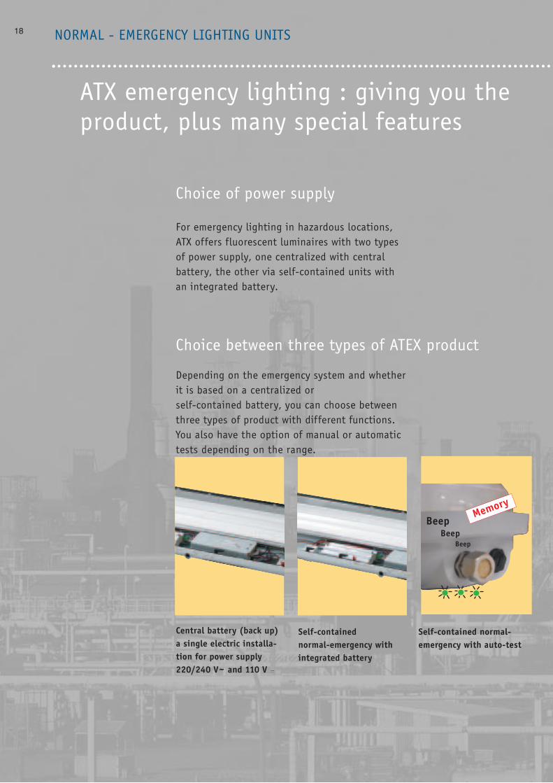
Choice between three types of ATEX product
Choice of power supply
NORMAL - EMERGENCY LIGHTING UNITS
For emergency lighting in hazardous locations,ATX offers fluorescent luminaires with two typesof power supply, one centralized with centralbattery, the other via self-contained units withan integrated battery.
Depending on the emergency system and whetherit is based on a centralized or self-contained battery, you can choose betweenthree types of product with different functions.You also have the option of manual or automatictests depending on the range.
ATX emergency lighting : giving you theproduct, plus many special features
BeepBeep
Beep
Memory
Central battery (back up)a single electric installa-tion for power supply 220/240 V~ and 110 V =
Self-contained normal-emergency withintegrated battery
Self-contained normal-emergency with auto-test

19
choice of power supply and type of benefits
The same benefits as the fluorescent range...
The normal-emergency bi-pin fluorescent lumi-naires incorporate all the technical benefits ofthe increased safety fluorescent range : safe closing, and easy maintenance. Work can also beperformed with the mains power switched on.
Plus three special benefits
In addition, normal-emergency bi-pin fluorescentluminaires have features specially designed fortheir applications. See photos below.
LED indicates that batteries are charging,and that the unit is ingood working order. Italso confirms feedback of information for auto-testdevices.
Two positive safety swit-ches allow work to be car-ried out with the mainspower switched on, by :- Cutting the mains power- Cutting the battery
power
Plug-in battery pack whichis easy to remove in situwith the mains power swit-ched on, for units withintegrated battery.

Twin tube through-wiring version • Supplied with
– Two M25 polyamide cable glands (sealed Ø: 8 to 18.5 mm)– One M25 blanking plug– Two 4 x 4 mm2 flexible or 4 x 6 mm2 rigid. connection terminal blocks
max.• 18W : Maintenance of tubes with mains power switched on, maintenance
of batteries, ballast and lampholders on site with mains power switchedoff
• 36W : Equipped with IP 2 X terminal strip cover, enabling maintenance ofthe batteries, ballast and lampholders with the mains power switched on
Tube (W) 1 tube Light Weight Volume Cat. No. Cat. No. Pack(not supplied) standby time output (Kg) (dm3) 110/127 V 220/240 V
2 x 18 3 h 29 % 7.3 32.3 0963 80 12 x 36 3 h 16 % 9.6 54.2 0913 81 0963 81 1
Twin tube pole mounting version• For mounting on pole or tubular wall-mounting support ø 42 mm with
one integrated M25 polyamide cable gland (sealed Ø 8 to 18.5 mm)• Supplied with one 3 x 4 mm2 connection terminal block and internal
bracket for anchoring the cable (positive safety)Tube (W) 1 tube Light Weight Volume Cat. No. Cat. No. Pack(not supplied) standby time output (Kg) (dm3) 110/127 V 220/240 V
2 x 18 W 3h 29 % 10 54.2 0913 92 0963 92 12 x 36 W 3 h 16 % 10.4 54.2 0913 93 0963 93 1
Fixing accessoriesCat. No. Pack
Set of 2 half clamps for fixing under 0965 93 1Ø 49 mm (1” 1/2) or Ø 42 mm (1” 1/4) tubeFor fixing under Ø 60 mm (2”) tube: 0965 91 1Set of 2 zinc-plated steel M8 ring bolts 0965 94 1for suspending the unit Ø 42 mm galvanized steel pole 0965 95 1for wall mounting Set of 2 aluminium brackets for fixing 0965 97 1unit to flat surface. 316 stainless steel version 0965 90 1Set of 2 aluminium hinged brackets for adjusting 0965 98 1direction of luminaire when wall-mounted.316 stainless steel version 0965 74 1Set of 2 zinc-plated steel brackets 0965 96 1for quick fixing with one hand316 stainless steel version 0965 89 1Fall prevention fixing kit 0964 05 1(1.20 m stainless steel chain) for M25 cable entry
For special options, please consult us :• 1 hr 30 mins standby time, remote batteries, other
voltages Dimensions of fixing accessories (see page 36-37)Installation and connection method (see page 38-39)Spare parts (see page 290)
18, 36 and 58 W fluorescent luminairesfor normal and emergency lighting• Ø 26 mm bi-pin tubes, standard G13 lampholders• Frequency : 50/60 Hz
• Common power supply circuit to provide both normal lighting and emergency lighting
• Power supply via high frequency electronic ballast according to model: 110/127 V ± 10% AC/DC or 220/240 V~ ± 10%, 198 to 264 V
• Instant start - Power factor ≥ 0.95• Battery voltage : 18 W : 6 V 4 A - 36 W/58W : 8.4 V 4 A
• Pre-impregnated fibre glass reinforced polyester body• Polycarbonate multi-parabolic hinged reflector• Polycarbonate diffuser hinged to body• High temperature internal wiring• Elastomer gasket• Anti-vibration lampholders with spring system
• Operation : mains power switched on : 2 or 3 tubes litmains power switched off : 1 tube lit (battery backed)
• Power supply to the unit (mains supply and battery) cut off by two positive safety switches which operate when diffuser is opened, for replacing tubes with mains power switched on
• Green LED on when the installation is operating normally and off in the event of a mains power supply failure or battery fault
• Battery-backed tube identified with green mark
• Battery pack easily interchangeable on site, fixed by screws and equippedwith a fast plug in connector
• Ballast and converter assembly fixed by screws, equipped with an anti-vibration fast connector
• Open and close using an Allen key or flat screwdriver (system automatically protects against over turning)
Standard twin, three-tube version• Supplied with one M25 polyamide cable gland
(sealed Ø : 8 to 18.5 mm) Two M25 blanking plugs• Equipped with an IP 2 X terminal strip cover for maintenance of batte-
ries, ballast and lampholders with mains power switched on• 18 W version: one 4 x 4 mm2 flexible or 4 x 6 mm2 rigid connection ter-
minal block max. including one earth terminal• 36/58W version: one 2 x 4 x 4 mm2 flexible or 2 x 4 x 6 mm2 rigid
connection terminal block max. including 2 earth terminals
Tube (W) 1 tube Light Weight Volume Cat. No. Cat. No. Pack(not supplied) standby time intensity (Kg) (dm3) 110/127 V 220/240 V
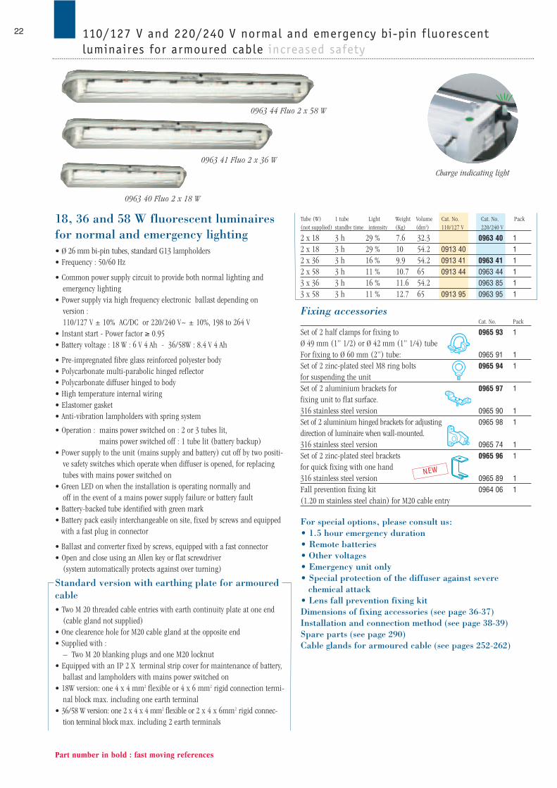
2 x 18 3 h 29 % 9.3 54.2 0913 70 12 x 18 3 h 29 % 7.3 32.3 0963 70 12 x 36 3 h 16 % 9.6 54.2 0913 71 0963 71 12 x 58 3 h 11% 10.7 65 0913 54 0963 54 13 x 36 3 h 16% 11.6 54.2 0913 84 0963 84 13 x 58 3 h 11% 12.7 65 0913 94 0963 94 1
20
0963 71 Fluo 2 x 36 W
0963 70 Fluo 2 x 18 W0963 92 Pole mounting fluo 2 x 18W
Charge indicating light
110/127 V - 220/240 V normal-emergency bi-pin f luorescent luminairesfor non-armoured cable increased safety
Part number in bold : fast moving references
NEW
0963 54 Fluo 2 x 58 W

21
TECHNICAL DATAZones :
• 1 and 2 and 21-22
Classification :
• According to CENELEC:
• Conforming to ATEX - 94/9 EC Directive and standards EN 50014-18-19-28
• EC 0081 II 2 G: for gas EEx edm II C T4 or T5 to Ta max. + 40°C
horizontal position, lighting facing downwards
• EC 0081 II 2 D - T = + 85°C : for dust
• According to IEC:
– Conforming to IEC standards 60079-0/1/7/18 Ex edsm II C T4 or T5 to Ta
max. +40°C, horizontal position, lighting facing downwards
DIP A21 TA = + 85°C
Approvals :
• Approved type FLe
• CENELEC LCIE 98 ATEX 6004
• IEC LCIE Ex 98.012
• declaration of conformity No. 50201
• Conforming to standards EN 60598-1 and IEC 60598-1 for luminaires
• Conforming to standards EN 50281-1-1 and IEC 61241-1-1
“combustible dust”
• Conforming to electromagnetic compatibility (EMC) standards
- EN 55015
- EN 61547
Protection index :
• IP 66/67 according to EN 60529 and IEC 60529
• Impact resistance : IK10 according to EN 50102
Operating temperature :
- 20°C to + 55°C (18/36W) ; - 20°C to + 40°C (58W)
Anticorrosion treatment and climate protection : see page G50
Positive safety :
• Safety switch for opening luminaire, see glossary
• Anti-wiring-error connector
“Dimmable” 3-tube operation :• Alternate use possible (1, 2 or 3 tubes) controlled by a double switch,
available on request
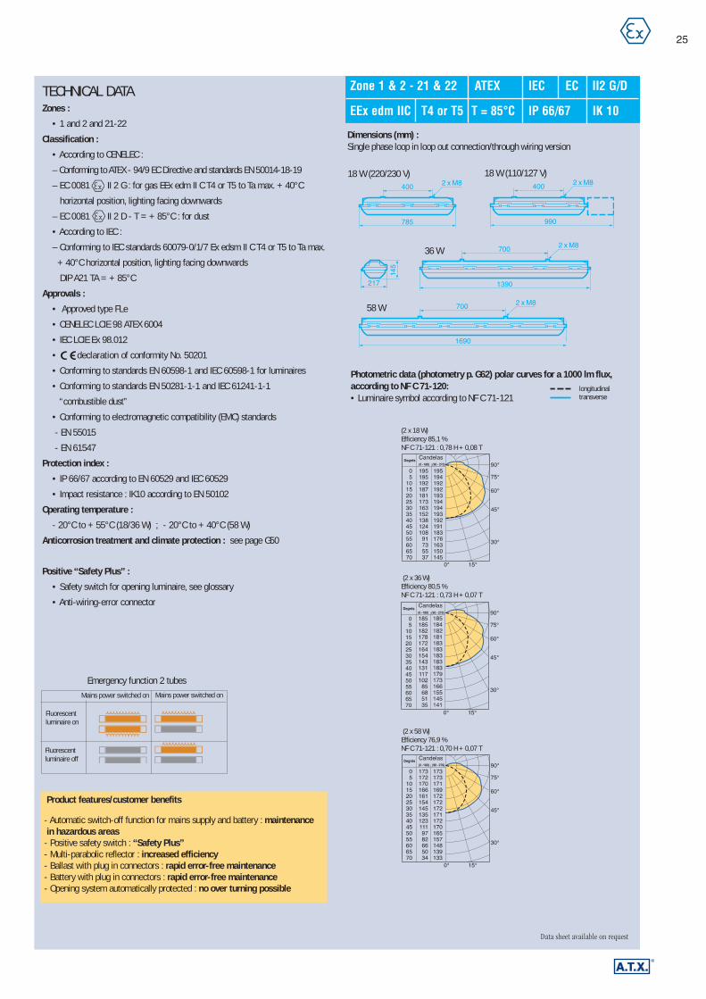
Photometric data (photometry p. G62) polar curves for a 1000 lm flux,according to NF C 71-120:• Luminaire symbol according to NF C 71-121
longitudinaltransverse
Emergency function 3 tubes Emergency function 2 tubes
258,5
50
217
145
785
1390
Ø 42
411
50
Ø 42
(18/36W)
Data sheet available on request
Zone 1 & 2 - 21 & 22 ATEX IEC EC II2 G/D
EEx edm IIC T4 or T5 T = 85°C IP 66/67 IK 10
Product features/customer benefits
- Automatic switch-off function for mains supply and battery :maintainability in hazardous locations
- Positive safety switch : “Safety Plus”- Multi-parabolic reflector : increased efficiency- Ballast with plug in connectors : rapid error-free maintenance- Battery with plug in connectors : rapid error-free maintenance- Opening system automatically protected : no over turning possible - Standard 3-tube : increased intensity, fewer units required- 3-tube “dimmable” : alternate use of the tubes with a double switch,flexibility of use
(1 x 36 W)Efficiency 89,3 %NF C 71-121 : 0,81 H + 0,08 T
(2 x 36 W)Efficiency 80,5 %NF C 71-121 : 0,73 H + 0,07 T
(3 x 36 W)Efficiency 68,1 %NF C 71-121 : 0,63 G + 0,05 T
(1 x 58 W)Efficiency 87,5 %NF C 71-121 : 0,80 H + 0,07 T
(2 x 58 W)Efficiency 76,9 %NF C 71-121 : 0,70 H + 0,07 T
(3 x 58 W)Efficiency 65,6 %NF C 71-121 : 0,61 G + 0,04 T
Pole mounting version :
Dimensions (mm) :Standard/through-wiring/pole mounting version :
Fluorescentluminaire on
Fluorescentluminaire on
Fluorescentluminaire off
Fluorescentluminaire off
Mains power on Mains power onMains power off Mains power off
Central tube lit 3 tubes lit 2 tubes lit
400
700
700
217
785
1390
1690
2 x M8
2 x M8
2 x M8
145
400
990
2 x M8
36 W
18 W (220/230 V) 18 W (110/127 V)
58 W
Tube (W) 1 tube Light Weight Volume Cat. No. Cat. No. Pack(not supplied) standby time intensity (Kg) (dm3) 110/127 V 220/240 V
2 x 18 3 h 29 % 7.6 32.3 0963 40 12 x 18 3 h 29 % 10 54.2 0913 40 12 x 36 3 h 16 % 9.9 54.2 0913 41 0963 41 12 x 58 3 h 11 % 10.7 65 0913 44 0963 44 13 x 36 3 h 16 % 11.6 54.2 0963 85 13 x 58 3 h 11 % 12.7 65 0913 95 0963 95 1
Fixing accessoriesCat. No. Pack
Set of 2 half clamps for fixing to 0965 93 1Ø 49 mm (1” 1/2) or Ø 42 mm (1” 1/4) tubeFor fixing to Ø 60 mm (2”) tube: 0965 91 1Set of 2 zinc-plated steel M8 ring bolts 0965 94 1for suspending the unit Set of 2 aluminium brackets for 0965 97 1fixing unit to flat surface. 316 stainless steel version 0965 90 1Set of 2 aluminium hinged brackets for adjusting 0965 98 1direction of luminaire when wall-mounted.316 stainless steel version 0965 74 1Set of 2 zinc-plated steel brackets 0965 96 1for quick fixing with one hand316 stainless steel version 0965 89 1Fall prevention fixing kit 0964 06 1(1.20 m stainless steel chain) for M20 cable entry
For special options, please consult us:• 1.5 hour emergency duration• Remote batteries• Other voltages • Emergency unit only• Special protection of the diffuser against severe
chemical attack• Lens fall prevention fixing kitDimensions of fixing accessories (see page 36-37)Installation and connection method (see page 38-39)Spare parts (see page 290)Cable glands for armoured cable (see pages 252-262)
22
Part number in bold : fast moving references
18, 36 and 58 W fluorescent luminairesfor normal and emergency lighting• Ø 26 mm bi-pin tubes, standard G13 lampholders• Frequency : 50/60 Hz
• Common power supply circuit to provide both normal lighting and emergency lighting
• Power supply via high frequency electronic ballast depending on version : 110/127 V ± 10% AC/DC or 220/240 V~ ± 10%, 198 to 264 V
• Instant start - Power factor ≥ 0.95• Battery voltage : 18 W : 6 V 4 Ah - 36/58W : 8.4 V 4 Ah
• Pre-impregnated fibre glass reinforced polyester body• Polycarbonate multi-parabolic hinged reflector• Polycarbonate diffuser hinged to body• High temperature internal wiring• Elastomer gasket• Anti-vibration lampholders with spring system
• Operation : mains power switched on : 2 or 3 tubes lit,mains power switched off : 1 tube lit (battery backup)
• Power supply to the unit (mains supply and battery) cut off by two positi-ve safety switches which operate when diffuser is opened, for replacingtubes with mains power switched on
• Green LED on when the installation is operating normally and off in the event of a mains power supply failure or battery fault
• Battery-backed tube identified with green mark• Battery pack easily interchangeable on site, fixed by screws and equipped
with a fast plug in connector
• Ballast and converter fixed by screws, equipped with a fast connector• Open and close using an Allen key or flat screwdriver
(system automatically protects against over turning)
Standard version with earthing plate for armouredcable• Two M 20 threaded cable entries with earth continuity plate at one end
(cable gland not supplied) • One clearence hole for M20 cable gland at the opposite end• Supplied with :
– Two M 20 blanking plugs and one M20 locknut• Equipped with an IP 2 X terminal strip cover for maintenance of battery,
ballast and lampholders with mains power switched on• 18W version: one 4 x 4 mm2 flexible or 4 x 6 mm2 rigid connection termi-
nal block max. including one earth terminal• 36/58 W version: one 2 x 4 x 4 mm2 flexible or 2 x 4 x 6mm2 rigid connec-
tion terminal block max. including 2 earth terminals
0963 41 Fluo 2 x 36 W
0963 40 Fluo 2 x 18 W
Charge indicating light
110/127 V and 220/240 V normal and emergency bi-pin f luorescent luminaires for armoured cable increased safety
NEW
0963 44 Fluo 2 x 58 W

23
TECHNICAL DATAZones :
• 1 and 2 and 21-22
Classification :
• According to CENELEC :
– Conforming to ATEX - 94/9 EC Directive and standards EN 50014-18-19
– EC 0081 II 2 G: for gas EEx edm II C T4 or T5 to Ta max. + 40°C
horizontal position, lighting facing downwards
– EC 0081 II 2 D - T = + 85°C : for dust
• According to IEC :
– Conforming to IEC standards 60079-0/1/7 Ex edsm II C T4 or T5 to Ta max.
+ 40°C horizontal position, lighting facing downwards
DIP A21 TA = + 85°C
Approvals :
• Approved type FLe
• CENELEC LCIE 98 ATEX 6004
• IEC LCIE Ex 98.012
• declaration of conformity No. 50201
• Conforming to standards EN 60598-1 and IEC 60598-1 for luminaires
• Conforming to standards EN 50281-1-1 and IEC 61241-1-1
“combustible dust”
• Conforming to electromagnetic compatibility (EMC) standards
- EN 55015 - EN 61547
Protection index :
• IP 66/67 according to EN 60529 and IEC 60529
• Impact resistance : IK10 according to EN 50102
Operating temperature :
- 20°C to + 55°C (18/36W) ; - 20°C to + 40°C (58W)
Anticorrosion treatment and climate protection :
• Page : G50
Positive “Safety Plus” :
• Safety switch for opening luminaire, see glossary
• Anti-wiring-error connector
“Dimmable” 3-tube operation :• Alternate use possible (1, 2 or 3 tubes) controlled by a double switch,
available on request
Data sheet available on request
Zone 1 & 2 - 21 & 22 ATEX IEC EC II2 G/D
EEx edm IIC T4 or T5 T = + 85°C IP 66/67 IK 10
36 W
18 W (220/230 V) 18 W (110/127 V)
Photometric data (photometry p. G62) polar curves for a 1000 lm flux,according to NF C 71-120:• Luminaire symbol according to NF C 71-121
longitudinaltransverse
58 W
Product features/customer benefits
- Automatic switch-off function for mains supply and battery : maintenancein hazardous areas
- Positive safety switch : “Safety Plus”- Multi-parabolic reflector : increased efficiency- Ballast with plug in connectors : rapid error-free maintenance- Battery with connectors : rapid error-free maintenance- Opening system automatically protected : no over turning possible - Standard 3-tube : increased intensity, fewer units required- 3-tube “dimmable” : alternate use of the tubes with a double switch,flexibility of use
(1 x 36 W)Efficiencyt 89,3 %NF C 71-121 : 0,81 H + 0,08 T
(2 x 36 W)Efficiency 80,5 %NF C 71-121 : 0,73 H + 0,07 T
(3 x 36 W)Efficiency 68,1 %NF C 71-121 : 0,63 G + 0,05 T
(1 x 58 W)Efficiency 87,5 %NF C 71-121 : 0,80 H + 0,07 T
(2 x 58 W)Efficiency 76,9 %NF C 71-121 : 0,70 H + 0,07 T
(3 x 58 W)Efficiency 65,6 %NF C 71-121 : 0,61 G + 0,04 T
Dimensions (mm) : Standard version
Emergency function 3 tubes Emergency function 2 tubes
Fluorescentluminaire on
Fluorescentluminaire on
Fluorescentluminaire off
Fluorescentluminaire off
Mains power on Mains power onMains power off Mains power off
400
700
700
217
785
1390
1690
2 x M8
2 x M8
2 x M8
145
400
990
2 x M8
Central tube lit 3 tubes lit 2 tubes lit

Catalogue numbersTube (W) 1 tube Light Weight Volume Cat. No. Cat. No. Pack(not supplied) standby time intensity (Kg) (dm3) 110/127 V 220/240 V
2 x 18 3 h 29% 7.6 32.3 0963 30 12 x 18 3 h 29% 10 54.2 0913 40(*) 12 x 36 3 h 16 % 9.9 54.2 0913 31 0963 31 12 x 58 3 h 11 % 10.7 65 0913 32 0963 32 1(*) reference 0913 40 possible installation methods :
- terminal position and connection : YES - through wiring : NO
Fixing accessoriesCat. No. Pack
Set of 2 half clamps for fixing to 0965 93 1Ø 49 mm (1” 1/2) or Ø 42 mm (1” 1/4) tubeFor fixing to Ø 60 mm (2”) tube: 0965 91 1Set of 2 zinc-plated steel M8 ring bolts 0965 94 1for suspending the unit Set of 2 aluminium brackets for fixing 0965 97 1unit to flat surface 316 stainless steel version 0965 90 1Set of 2 aluminium hinged brackets for adjusting 0965 98 1the direction of the luminaire when wall-mounted316 stainless steel version 0965 74 1Set of 2 zinc-plated steel brackets for 0965 96 1quick fixing with one hand316 stainless steel version 0965 89 1Fall prevention fixing kit 0964 06 1(1.20 m stainless steel chain) for M20 cable entry
For special options, please consult us : • 1,5 hour emergency duration• Remote battery• Other voltages• Lens fall prevention fixing kitDimensions of fixing accessories (see page 36-37)Installation and connection method (see page 38-39)Spare parts (see page 290)Cable glands for armoured cable (see pages 252-262)
24
Part number in bold : fast moving references
18, 36 and 58 W fluorescent luminairefor normal and emergency lighting• Ø 26 mm bi-pin tubes, standard G13 lampholders• Designed for single phase mains supplies with a choice of possible
installation methods: terminal position, connection and through wiring• Frequency : 50/60 Hz
• Common power supply circuit to provide both normal lighting and emergency lighting
• Power supply via high frequency electronic ballast depending on theversion : 110/127 V ± 10% AC/DC or 220/240 V~ ± 10%, 198 to 264 V
• Instant start - Power factor ≥ 0.95• Battery voltage : 18 W : 6 V 4 Ah - 36/58W : 8.4 V 4 Ah
• Pre-impregnated fibre glass reinforced polyester body• Polycarbonate multi-parabolic hinged reflector• Polycarbonate diffuser hinged to body• High temperature internal wiring• Elastomer gasket• Anti-vibration lampholders with spring system
• Operation: mains power switched on : 2 tubes litmains power switched off : 1 tube lit (battery backup)
• Power supply to the unit (mains supply and battery) cut off by two positivesafety switches, which operate when diffuser is opened, for replacing tubeswith mains power switched on
• Green LED on when the installation is operating normally and off in the event of a mains power supply failure or a battery fault
• Battery-backed tube identified with green mark
• Open and close using an Allen key or flat screwdriver (system automatically protects against over turning)
• Battery pack easily interchangeable on site, fixed by screws and equippedwith a fast plug in connector
• Ballast and converter fixed by screws, equipped with a fast connector• 36/58 W equipped with an IP 2 X terminal strip cover for maintenance of
battery, ballast and lampholders with mains power switched on• 18W maintenance of the tubes with the mains power switched on, mainte-
nance of the battery, ballast and lampholders with the mains powerabsent.
• Three threaded cable entries with earthing plates for M20 cable gland (notsupplied) for armoured cable
• Supplied with: – Two M20 blanking plugs – 18 W : 4 X 4 mm2 flexible or 8 x 6 mm2 rigid connection terminal block
max. including one earth terminal at one end – One 4 x 4 mm2 flexible or 4 x 6 mm2 rigid loop in loop out terminal block
including one earth terminal at the other end
0963 30 Fluo 2 x 18 W
Charge indicating light
110/127 V or 220/240 V single phase loop in loop out connection and through wiring normal-emergency for armoured cable increased safety
NEW
0963 31 Fluo 2 x 36 W
0963 22 Fluo 2 x 58 W
25
TECHNICAL DATAZones :
• 1 and 2 and 21-22
Classification :
• According to CENELEC :
– Conforming to ATEX - 94/9 EC Directive and standards EN 50014-18-19
– EC 0081 II 2 G : for gas EEx edm II C T4 or T5 to Ta max. + 40°C
horizontal position, lighting facing downwards
– EC 0081 II 2 D - T = + 85°C : for dust
• According to IEC :
– Conforming to IEC standards 60079-0/1/7 Ex edsm II C T4 or T5 to Ta max.
+ 40°C horizontal position, lighting facing downwards
DIP A21 TA = + 85°C
Approvals :
• Approved type FLe
• CENELEC LCIE 98 ATEX 6004
• IEC LCIE Ex 98.012
• declaration of conformity No. 50201
• Conforming to standards EN 60598-1 and IEC 60598-1 for luminaires
• Conforming to standards EN 50281-1-1 and IEC 61241-1-1
“combustible dust”
• Conforming to electromagnetic compatibility (EMC) standards
- EN 55015
- EN 61547
Protection index :
• IP 66/67 according to EN 60529 and IEC 60529
• Impact resistance : IK10 according to EN 50102
Operating temperature :
- 20°C to + 55°C (18/36 W) ; - 20°C to + 40°C (58 W)
Anticorrosion treatment and climate protection : see page G50
Positive “Safety Plus” :
• Safety switch for opening luminaire, see glossary
• Anti-wiring-error connector
36 W
18 W (220/230 V) 18 W (110/127 V)
Photometric data (photometry p. G62) polar curves for a 1000 lm flux,according to NF C 71-120:• Luminaire symbol according to NF C 71-121
longitudinaltransverse
Dimensions (mm) :Single phase loop in loop out connection/through wiring version
58 W
Data sheet available on request
Emergency function 2 tubes
Zone 1 & 2 - 21 & 22 ATEX IEC EC II2 G/D
EEx edm IIC T4 or T5 T = 85°C IP 66/67 IK 10
(2 x 18 W)Efficiency 85,1 %NF C 71-121 : 0,78 H + 0,08 T
(2 x 36 W)Efficiency 80,5 %NF C 71-121 : 0,73 H + 0,07 T
(2 x 58 W)Efficiency 76,9 %NF C 71-121 : 0,70 H + 0,07 T
Fluorescentluminaire on
Fluorescentluminaire off
Mains power switched on Mains power switched on
Product features/customer benefits
- Automatic switch-off function for mains supply and battery : maintenance in hazardous areas
- Positive safety switch : “Safety Plus”- Multi-parabolic reflector : increased efficiency- Ballast with plug in connectors : rapid error-free maintenance- Battery with plug in connectors : rapid error-free maintenance- Opening system automatically protected : no over turning possible
400
700
700
217
785
1390
1690
2 x M8
2 x M8
2 x M8
145
400
990
2 x M8

Fixing accessoriesCat. No. Pack
Set of 2 half clamps for fixing to 0965 93 1Ø 49 mm (1” 1/2) or Ø 42 mm (1” 1/4) tubeFor fixing to Ø 60 mm (2”) tube 09665 91 1Set of 2 zinc-plated steel M8 ring bolts 0965 94 1for suspending the unit Set of 2 aluminium brackets for fixing 0965 97 1unit to flat surface. 316 stainless steel version 0965 90 1Set of 2 aluminium hinged brackets for adjusting 0965 98 1direction of luminaire when wall-mounted.316 stainless steel version 0965 74 1Set of 2 zinc-plated steel brackets for 0965 96 1quick fixing 316 stainless steel version 0965 89 1Fall prevention fixing kit 0964 06 1(1.20 m chain) for M20 cable entryFall prevention fixing sling 0964 05 1(1.20 m stainless steel chain) for M25 cable entry
For special options, please consult us :• Through wiring and pole mounting versions• Single tube and Fa6 tube versions• Ø 38 mm bi-pin tubes• Ø 38 mm bi-pin tubes specially designed for low
temperatures • Special protection of the diffuser against severe
chemical attack• Lens fall prevention fixing kitDimensions of fixing accessories (see page 36-37) Installation and connection method (see page 38-39)Spare parts (see page 290)Cable glands for armoured cable (see pages 252-262)
26
Part number in bold : fast moving references
220/240 V AC or 110 V DC normal and emergency bi-pin luminaires forcentral source for armoured and non-armoured cable increased safety
0963 12 Fluo 2 x 36W
0963 10 Fluo 2 x 18W
NEW
18 and 36 W fluorescent luminaires• Ø 26 mm bi-pin tubes, standard G 13 lampholders• Power supply via high frequency ballast for alternate use:
– in normal mode: 220/240 V~ ± 10%, 198 to 264 V 50/60 Hz – in battery back up mode 3 hours maximum: 110 V DC on remote
battery powered by the mains supply• Pre-impregnated fibre glass reinforced polyester body• Polycarbonate diffuser hinged to body• Polycarbonate multi-parabolic hinged reflector• High temperature internal wiring• Elastomer gasket• Anti-vibration lampholders with spring system• Power supply to the unit cut off by positive safety switch which operateswhen diffuser is opened, for replacing tubes with mains power switched on• If one tube fails, the other tube remains lit.• Open and close using an Allen key or flat screwdriver (system automati-cally protects against over turning)• IP 2X terminal strip cover for maintaining the ballast and lampholderswithout cutting off the mains power supply• Ballast fixed by screws, equipped with a fast connector
Standard twin version for non-armoured cable• Three threaded cable entries, 2 at one end and the third at the opposite
end for M25 cable gland.• Supplied with:
– One M25 polyamide cable gland (sealed Ø 8 to 18.5 mm)– Two M25 blanking plugs– One 5 x 4 mm2 max. flexible or 5 x 6 mm2 max. rigid connectionterminal block
Tube (W) Light Weight Volume Cat. No. Packnot supplied output (Kg) (dm3) 220/240 V
2 x 18 100 % 5.5 32.3 0963 10 12 x 36 100 % 7.9 54.2 0963 12 1
Standard twin version for armoured cable• Two M20 threaded cable entries with earth continuity plate for cable gland
(not supplied) for armoured cable at one end • One clearence hole for M20 cable gland at the opposite end• Supplied with:
– Two M20 blanking plugs and one M20 locknut– One 5 x 4 mm2 max. flexible or 5 x 6 mm2 max. rigid connection
terminal block Tube (W) Light Weight Volume Cat. No. Packnot supplied output (Kg) (dm3) 220/240V
2 x 18 100 % 5.5 32.3 0963 18 12 x 36 100 % 7.9 54.2 0963 20 1

27
Data sheet available on request
TECHNICAL DATAZones :
• 1 and 2 and 21-22
Classification :
• According to CENELEC:
– Conforming to ATEX - 94/9 EC Directive and standards EN 50014-18-19
– EC 0081 II 2 G : for gas EEx ed II C T4 or T5 to Ta max. + 40°C horizon-
tal position, lighting facing downwards.
– EC 0081 II 2 D T = + 85°C : for dust
• According to IEC :
– Conforming to IEC standards 60079-0/1/7 Ex eds II C T4 or T5 to Ta max.
+ 40°C horizontal position, lighting facing downwards.
DIP A21 TA = + 85°C
Approvals :
• Approved type Fle
• CENELEC LCIE 98 ATEX 6004
• IEC LCIE Ex 98.012
• declaration of conformity No. 50201
• Conforming to standards EN 60598-1 and IEC 60598-1 for luminaires
• Conforming to EN 50281-1-1 and IEC 61241-1-1 “combustible dust”
• Conforming to electromagnetic compatibility (EMC) standards
- EN 55015
- EN 61547
Protection index :
• IP 66/67 according to EN 60529 and IEC 60529
• Impact resistance : IK10 according to EN 50102
Operating temperature :
- 20°C to + 55°C
Anticorrosion treatment and climate protection : see page G50
Positive safety :
• Safety switch for opening luminaire, see glossary
• Anti-wiring-error connector
Dimensions (mm) :
258,5
50
217
145
785
1390
Ø 42
411
50
Ø 42
Zone 1 & 2 - 21 & 22 ATEX IEC EC II2 G/D
EEx ed IIC T4 or T5 T = 85°C IP 66/67 IK 10
36 W
18 W
Product features/customer benefits- Positive safety switch : “Safety Plus”- Multi-parabolic reflector : increased efficiency- Ballast with plug in connectors : rapid error-free maintenance- Opening system automatically protected : no over turning possible
(2 x 36 W)Efficiency 80,5 %NF C 71-121 : 0,73 H + 0,07 T
(2 x 18 W)Efficiency 85,1 %NF C 71-121 : 0,78 H + 0,08 T
Photometric data (photometry p. G62) polar curves for a 1000 lm flux,according to NF C 71-120:• Luminaire symbol according to NF C 71-121
longitudinaltransverse

Standard twin version for non-armoured cable • Supplied with :
– One M25 polyamide cable gland (sealed Ø: 8 to 18.5mm)– Two M25 blanking plugs
• 18W version : one 4 x 4 mm2 flexible or 4 x 6 mm2 rigid connection ter-minal block max. including one earth terminal
• 36/58 W version: one 2 x 4 x 4 mm2 flexible or 2 x 4 x 6mm2 rigid con-nection terminal block max. including 2 earth terminals
Tube (W) 1 tube Light Weight Volume Cat. No Packnot supplied standby intensity (kg) (dm3) 230/240 V
2 x 18 3 h 24 % 7.6 32.3 0963 17 12 x 36 3 h 16 % 9.9 54.2 0963 19 12 x 58 3 h 15 % 11 65 0963 38 1
Fixing accessoriesCat. No. Pack
Set of 2 half clamps for fixing to 0965 93 1Ø 49mm (1“ 1/2) or Ø 42mm (1” 1/4) tubeFor fixing to Ø 60 mm (2“) tube 0965 91 1Set of 2 zinc-plated steel M8 ring bolts 0965 94 1for suspending the unit Set of 2 aluminium brackets for 0965 97 1fixing unit to flat surface. 316 stainless steel version 0965 90 1Set of 2 aluminium hinged brackets for adjusting 0965 98 1direction of luminaire when wall-mounted..316 stainless steel version 0965 74 1Set of 2 zinc-plated steel brackets for 0965 96 1quick fixing with one hand316 stainless steel version 0965 89 1Fall prevention fixing kit 0964 05 1(1.20 m stainless steel chain) for M25 cable entry
For special options, please consult us :• Other voltages• Ø 38 mm bi-pin tubes• Ø 38 mm bi-pin tubes specially designed for low
temperatures • Special protection of the diffuser against severe chemi-cal attack• Lens fall prevention fixing kitDimensions of fixing accessories (see page 36-37)Installation and connection method (see page 38-39)Spare parts (see page 290)
28
Part number in bold : fast moving references
18, 36 and 58 W auto-test fluorescentluminaires for normal and emergencylighting• Ø 26 mm mono and bi-pin tubes, standard G13 lampholders• Frequency: 50/60 Hz
• Common power supply circuit to provide both normal lighting and emer-gency lighting
• Power supply via high frequency ballast 230/240 V~ ± 6%; 216 to 256 V~• Instant start - Power factor ≥ 0.96• Battery voltage : 18W, 36W and 58W - 6V
• Pre-impregnated fibre glass reinforced polyester body• Polycarbonate multi-parabolic hinged reflector• Polycarbonate diffuser hinged to body• High temperature internal wiring• Elastomer gasket• Anti-vibration lampholders with spring system
• Power supply to the unit (mains supply and battery) cut off by two posi-tive safety switches which operate when diffuser is opened, for replacingtubes with mains power switched on
• Operation : mains power switched on : 2 tubes lit mains power switched off : 1 tube lit (battery backed)
• Automatic tests controlled by microprocessor:– monthly : discharge for 5 minutes – 6-monthly : discharge for 1 hour – annual : discharge for 3 hours with indication (upon request) of
the number of months remaining before the next test• In the event of a fault:
– LED flashes– Buzzer emits 3 long beeps every 35 minutes until the repair is carriedout
• Battery-backed tube identified with green mark
• Open and close using an Allen key or flat screwdriver (system automati-cally protects against over turning)
• battery pack easily interchangeable on site, fixed by screws and equippedwith a fast connector• Ballast and converter fixed by screws, equipped with a fast connector
230/240 V “self-test” normal and emergency bi-pin f luorescent luminairesfor non-armoured cable increased safety
BeepBeep
Beep
Memory
0963 17 Fluo 2 x 18W
Visible and audible fault signal
NEW
0963 38 Fluo 2 x 58W
0963 19 Fluo 2 x 36W

29
TECHNICAL DATA
Zones : 1 and 2 and 21-22
Classification:
• According to CENELEC:
– Conforming to ATEX - 94/9 EC Directive and standards EN 50014-18-19
– EC 0081 II 2 G : for gas EEx ed IIC* T4 or T5 to Ta max. + 40°C hori-
zontal position, lighting facing downwards.
– EC 0081 II 2 D T = + 85°C : for dust
• According to IEC:
– Conforming to IEC standards 60079-0/1/7 Ex eds IIC* T4 or T5 to Ta max.
+ 40°C horizontal position, lighting facing downwards.
DIP A21 TA = + 85°C
* IIB with external buzzer
Approvals :
• Approved type Fle
• CENELEC LCIE 98 ATEX 6004
• IEC LCIE Ex 98.012
• declaration of conformity No. 50201
• Conforming to standards EN 60598-1 and IEC 60598-1 for luminaires
• Conforming to EN 50281-1-1 and IEC 61241-1-1 “combustible dust”
• Conforming to electromagnetic compatibility (EMC) standards
- EN 55015 - EN 61547
Protection index :
• IP 66/67 according to EN 60529 and IEC 60529
• Impact resistance : IK10 according to EN 50102
Operating temperature : - 20°C to + 55°C (18/36 W) ; -20°C to + 40°C (58 W)
Dimensions (mm) :
400 700
700
217
785 1390
1690
2 x M8 2 x M8
2 x M8
145
Zone 1 & 2 - 21 & 22 ATEX IEC EC II2 G/D
EEx ed IIC or IIB T4 or T5 T = 85°C IP 66/67 IK 10
36 W18 W
58 W
Product features/customer benefits
- Positive safety switch : “Safety Plus”- Multi-parabolic reflector : increased efficiency- Ballast with plug in connectors : rapid error-free maintenance- Battery with connectors : rapid error-free maintenance- Opening system automatically protected : no over turning possible- Automatic tests with alarm and memory : easy maintenance
visual indication
Mémorisation of tests
Easy maintenance
BeepBeep
Beep
External audible indication
Memory
(2 x 18 W)Efficiency 85,1 %NF C 71-121 : 0,78 H + 0,08 T
(2 x 36 W)Efficiency 80,5 %NF C 71-121 : 0,73 H + 0,07 T
(2 x 58 W)Efficiency 76,9 %NF C 71-121 : 0,70 H + 0,07 T
NORMAL AND EMERGENCY BI-PIN FLUORESCENT LUMINAIRES
Self-test with integratedalarm and memory
The LED indicates: - Charging status of battery
and charger- Presence of mains power- State of the lamps
- 3 long beeps every 35 minuntil the fault is repaired- 1 beep each time the unitis switched on confirms theunit is in good workingorder.
The microprocessor indicatesthe number of months remai-ning before the next annual3-hour discharge test.
- On-site maintenance- Plug-in with connector- Quick fixing- Integrated battery
ATX : “Safety Plus”Battery discharge tests: 5-minute monthly test, 1-hour halfyear test, 3-hour yearly test. Results of the tests :• LED on with steady light > battery present, charged
> satisfactory charging current> mains supply present
and connected. LED flashing > lamp fault . LED off > battery fault
> no mains supply

Standard version for armoured cable• Two M20 threaded cable entries with earth continuity plate for armoured
cables at one end (cable gland not supplied) • One clearance hole for M20 cable gland at the opposite end. • Supplied with :
– Two blanking plugs and one M20 locknut– One 5 x 4 mm2 max. flexible or 5 x 6 mm2 max. rigid connection
terminal block Tube (W) Weight Volume Cat. No. Cat No. Packnot supplied (Kg) (dm3) 110/127 V 220/240 V
2 x 18/20 7.54 54.2 0913 67 12 x 18/20 5.54 32.3 0963 67 12 x 36/40 7.88 54.2 0913 69 0963 69 12 x 58/65 9.00 65 0913 82 0963 82 1
Fixing accessoriesCat. No. Pack
Set of 2 half clamps for fixing to 0965 93 1Ø 49 mm (1” 1/2) or Ø 42 mm (1” 1/4) tubeFor fixing to Ø 60 mm (2”) tube : 0965 91 1Set of 2 zinc-plated steel M8 ring bolts 0965 94 1for suspending the unit Set of 2 aluminium brackets for fixing 0965 97 1on flat surface. 316 stainless steel version 0965 90 1Set of 2 aluminium hinged brackets for adjusting 0965 98 1direction of luminaire when wall-mounted.316 stainless steel version 0965 74 1Set of 2 zinc-plated steel brackets 0965 96 1quick fixing with one hand316 stainless steel version 0965 89 1Fall prevention fixing kit 0964 06 1(1.20 m stainless steel chain) for M20 cable entryFall prevention fixing kit 0964 05 1(1.20 m stainless steel chain) for M25 cable entry
Adaptor for Fa8 tube on Fa 6 lampholders 0969 05 1
For special options, please consult us: • Electronic ballast 254 V 50/60 Hz + 6% - 10% • Pole mounting and through wiring versions • Single version (1 x 18 W - 1 x 36 W - 1 x 58 W) • Special protection of the diffuser against severe
chemical attack • Lens fall prevention fixing kitDimensions of fixing accessories (see page 36-37) Installation and connection method (see page 38-39)Spare parts (see page 290)Cable glands for armoured cable (see pages 252-262)
18/20, 36/40 and 58/65W fluorescentluminaires • Ø 38 mm (20, 40 and 65 W) and Ø 26 mm (20, 36 and 58 W) mono-pin
tubes with Fa 6 lampholders according to IEC 60061-1• Power supply via high frequency ballast depending on version : 99 to 140
V 110/127 V ± 10% AC/DC or 220/240 V~ ± 10%, 198 to 264 V• Frequency: 50/60 Hz• Instant start. Power factor ≥ 0.95• Pre-impregnated fibre glass reinforced polyester body• Polycarbonate multi-parabolic hinged reflector• Polycarbonate diffuser hinged to body• Elastomer gasket• High temperature internal wiring• Anti-vibration lampholders with spring system• Separate operation of the tubes: if one tube fails, the other tube remains
lit• Power supply to the unit cut off by positive safety switch which operates
when diffuser is opened, for replacing tubes with mains power switchedon
• Open and close using an Allen key or flat screwdriver (system automati-cally protects against over turning)
• IP 2X terminal strip cover for maintaining the ballast and lampholderswithout cutting off the main power supply• Ballast fixed by screws, equipped with a fast connector
Standard version for non-armoured cable• Three threaded cable entries, 2 at one end and the third at the opposite
end for M25 cable gland.• Supplied with:
– One M25 polyamide cable gland (sealed Ø: 8 to 18.5 mm)– Two M25 blanking plugs– One 5 x 4 mm2 flexible or 5 x 6mm2 rigid connection terminal
block maximum.Tube (W) Weight Volume Cat. No. Cat No. Packnot supplied (Kg) (dm3) 110/127 V 220/240 V
2 x 18/20 7.54 54.2 0915 79 12 x 18/20 5.54 32.3 0965 79 12 x 36/40 7.88 54.2 0915 88 0965 88 12 x 58/65 9.00 65 0915 50 0965 50 1
30
Part number in bold : fast moving references
0969 05 Adaptator for Fa8 tube onFa6 lampholder
0965 50 Fluo 2 x 58W
0965 79 Fluo 2 x 18W
110/127 V - 220/240 V mono-pin f luorescent luminaires for armoured ornon-armoured cable increased safety
NEW
0965 88 Fluo 2 x 36W

TECHNICAL DATAZones :
• 1 and 2, and 21-22
Classification :
• According to CENELEC :
• Conforming to ATEX - 94/9 EC directive and standards NP EN 50014-18-19
• EC 0081 II 2 G: for gas EEx ed II C T4 or T5 to Ta max. + 40°C
horizontal position, lighting facing downwards
• EC 0081 II 2 D - T = + 85°C : for dust
• According to IEC :
• Conforming to IEC standards 60079-0/1/7 Ex ed II C T4 or T5 to Ta max.
+ 40°C horizontal position, lighting facing downwards
DIP A21 TA = + 85°C
Approvals :
• Approved type Fle
• CENELEC LCIE 98 ATEX 6004
• IEC LCIE Ex 98.012
• declaration of conformity No. 50201
• Conforming to standards EN 60598-1 and IEC 60598-1 for luminaires
• Conforming to EN 50281-1-1 and IEC 61241-1-1 “combustible dust”
• Conforming to electromagnetic compatibility (EMC) standards
EN 55015 – EN 61547
Protection index :
• IP 66/67 according to EN 60529 and IEC 60529
• Impact resistance: IK10 according to EN 50102
Operating temperature :
- 20°C to + 55°C
Anticorrosion treatment and climate protection : see page G50
Positive safety :
• Safety switch for opening luminaire, see glossary
• Anti-wiring-error connector
31
Data sheet available on request
Dimensions (mm) :
18 W 36 W
400 700
700
217
785 1390
1690
2 x M8 2 x M8
2 x M8
145
58 W
Zone 1 & 2 - 21 & 22 ATEX IEC EC II2 G/D
EEx ed IIC T4 or T5 T = 85°C IP 66/67 IK 10
Product features/customer benefits- Positive safety switch: “Safety Plus”- Multi-parabolic reflector: increased efficiency- Ballast with plug in connectors: rapid error-free maintenance- Opening system automatically protected : no over turning possible
(2 x 18 W)Efficiency 85,1 %NF C 71-121 : 0,78 H + 0,08 T
(2 x 36 W)Efficiency 80,5 %NF C 71-121 : 0,73 H + 0,07 T
(2 x 58 W)Efficiency 76,9 %NF C 71-121 : 0,70 H + 0,07 T
Photometric data (photometry p. G62) polar curves for a 1000 lm flux,according to NF C 71-120 :• Luminaire symbol according to NF C 71-121
longitudinaltransverse

Standard version with earthing plate for armouredcable• Two M20 threaded cable entries with earth continuity plate at one end
(cable gland not supplied) • One clearance hole for M20 cable gland at the opposite end• Supplied with:
– Two M20 blanking plugs and one M20 locknutTube (W) 1 tube Light Weight Volume Cat. No. Packnot supplied standby time output (Kg) (dm3) 220/240 V
2 x 18/20 3 hrs 29% 7.6 32.3 0969 20 12 x 36/40 3 hrs 16% 9.9 54.2 0969 21 12 x 58/65 3 hrs 11% 9 65 0969 22 1
Fixing accessoriesCat. No. Pack
Set of 2 half clamps for fixing to 0965 93 1Ø 49 mm (1“ 1/2) or Ø 42 mm (1” 1/4) tubeFor fixing to Ø 60 mm (2“) tube 0965 91 1Set of 2 zinc-plated steel M8 ring bolts 0965 94 1for suspending the unit Set of 2 aluminium brackets for fixing 0965 97 1unit on flat surface. 316 stainless steel version 0965 90 1Set of 2 aluminium hinged brackets for adjusting 0965 98 1direction of luminaire when wall-mounted.316 stainless steel version 0965 74 1Set of 2 zinc-plated steel brackets for 0965 96 1quick fixing with one hand316 stainless steel version 0965 89 1Fall prevention fixing kit(1.20 m stainless steel chain) for M20 cable entry 0964 06 1Fall prevention fixing kit (1.20 m stainless steel chain) for M25 cable entry 0964 05 1
Adaptor for Fa8 tube 0969 05 1
For special options, please consult us: • 1,5 hour emergency duration• External battery • Other voltages• Special protection of the diffuser against severe chemi-cal attack • Lens fall prevention fixing kitDimensions of fixing accessories (see page 36-37) Installation and connection method (see page 38-39)Spare parts (see page 290 )Cable glands for armoured cable (see pages 252-262)
32
Part number in bold : fast moving references
Charge indicating light
0969 11 Fluo 2 x 36W
0969 10 Fluo 2 x 18W
NEW
220/240 V normal and emergency mono-pin f luorescent luminaires for armoured or non-armoured cable increased safety
18/20, 36/40 and 58/65W fluorescentluminaires• Ø 38 mm (20, 40 and 65 W) and Ø 26 mm (18, 36 and 58 W) mono-pin
tubes with Fa 6 lampholder according to IEC 60061-1• Frequency : 50/60 Hz• Power supply : high frequency ballast 220/240V~ (+ 6%, - 10%) 198 to 264 V• Instant start. Power factor ≥ 0.95• Battery voltage: 18W 6V 4A h - 36/58W 8.4V 4A h
• Pre-impregnated fibre glass reinforced polyester body• Polycarbonate multi-parabolic hinged reflector• Polycarbonate diffuser hinged to body• High temperature internal wiring• Elastomer gasket• Anti-vibration lampholder with spring system• Common power supply circuit to provide both normal lighting and emer-
gency lighting
• Operation : mains power switched on, 2 tubes lit mains power switched off, 1 tube lit (battery backed)
• Power supply to the unit (mains supply and battery) cut off by two posi-tive safety switches which operate when diffuser is opened, for replacingtubes with mains power switched on
• Green LED on when the installation is operating normally and off if thereis a mains power supply failure or a battery fault
• Battery-back up tube identified with green mark• Battery pack easily interchangeable on site, fixed by screws and equipped
with a fast connector• Ballast and converter fixed by screws, equipped with a fast connector• Open and close using an Allen key or flat screwdriver (system automati-
cally protects against over turning)• Equipped with an IP 2 X terminal strip cover for maintenance of
battery, ballast and lampholders with mains power switched on• 18W version: one 4 x 4 mm2 flexible or 4 x 6 mm2 rigid connection termi-
nal block max. including one earth terminal• 36/58 W version: one 2 x 4 x 4 mm2 flexible or 2 x 4 x 6mm2 rigid con-
nection terminal block max. including 2 earth terminals
Standard version for non-armoured cable• Three threaded cble entries for M25 cable glands. Supplied with:
– One M25 polyamide cable gland (sealed Ø: 8 to 18.5mm) – Two M25 blanking plugs
Tube (W) 1 tube Light Weight Volume Cat. No. Packnot supplied standby time output (Kg) (dm3) 220/240V
2 x 18/20 3 h 29 % 7.6 32.3 0969 10 12 x 36/40 3 h 16 % 9.9 54.2 0969 11 12 x 58/65 3 h 11 % 11 65 0969 12 1
0969 12 Fluo 2 x 58W
TECHNICAL DATAZones :
• 1 and 2, and 21-22
Classification :
• According to CENELEC :
• Conforming to ATEX - 94/9 EC Directive and standards EN 50014-18-19-28
• EC 0081 II 2 G : for gas EEx edm II C T4 or T5 to Ta max. + 40°C
horizontal position, lighting facing downwards.
• EC 0081 II 2 D - T = + 85°C : for dust
• According to IEC :
• Conforming to IEC standards 60079-0/1/7/18 Ex edm II C T4 or T5 to Ta
max. + 40°C horizontal position, lighting facing downwards.
DIP A21 TA = + 85°C
Approvals :
• Approved type Fle
• CENELEC LCIE 98 ATEX 6004
• IEC LCIE Ex 98.012
• declaration of conformity No. 50201
• Conforming to standards EN 60598-1 and IEC 60598-1 for luminaires
• Conforming to standards EN 50281-1-1 and IEC 612241-1-1
“combustible dust”
• Conforming to electromagnetic compatibility (EMC) standards
EN 55015 and EN 61547
Protection index :
• IP 66/67 according to EN 60529 and IEC 60529
• Impact resistance : IK10 according to EN 50102
Operating temperature :
– 20°C to + 55°C
Anticorrosion treatment and climate protection : see page G50
Positive safety :
• Safety switch for opening contacts
• Anti-wiring-error connector
33
Data sheet available on request
Dimensions (mm) :
• Standard/through-wiring version
18 W 36 W
400 700
700
217
785 1390
1690
2 x M8 2 x M8
2 x M8
145
58 W
Zone 1 & 2 - 21 & 22 ATEX IEC EC II2 G/D
EEx edm IIC T4 or T5 T = 85°C IP 66/67 IK 10
(2 x 18 W)Efficiency 85,1 %NF C 71-121 : 0,78 H + 0,08 T
(2 x 36 W)Efficiency 80,5 %NF C 71-121 : 0,73 H + 0,07 T
(2 x 58 W)Efficiency 76,9 %NF C 71-121 : 0,70 H + 0,07 T
Photometric data (photometry p. G62) polar curves for a 1000 lm flux,according to NF C 71-120:• Luminaire symbol according to NF C 71-121
longitudinaltransverse
Product features/customer benefits- Positive safety switch: “Safety Plus”- Multi-parabolic reflector: increased efficiency- Ballast with plug in connectors: rapid error-free maintenance- Ballast with connectors: rapid error-free maintenance- System automatically protected : no over turning possible

Fixing accessoriesCat. No. Pack
Set of 2 half clamps for fixing to 0965 93 1Ø 49 mm (1” 1/2) or Ø 42 mm (1” 1/4) tubeFor fixing to Ø 60 mm (2”) tube 0965 91 1Set of 2 aluminium brackets for 0965 97 1fixing unit to flat surface316 stainless steel version 0965 90 1Set of 2 aluminium hinged brackets for adjusting 0965 98 1direction of luminaire when wall-mounted.316 stainless steel version 0965 74 1Set of 2 zinc-plated steel brackets for 0965 96 1quick fixing with one hand316 stainless steel version 0965 89 1
For special options, please consult us: • Ø 38 mm standard or bi-pin tubes specially designed
for low temperatures • Special protection of the diffuser against severe
chemical attackDimensions of fixing accessories (see page 36-37) Installation and connection method (see page 38-39)Spare parts (see page 290) Timer switch (see page 211)
34
Part number in bold : fast moving references
0965 32 level gauge light fitting 1 x 36W
Installation invertical position
NEW
110/127 V - 220/240 V level gauge light fitting for non-armoured cable increased safety
18, 36 and 58 W level gauge light fitting• Ø 26 mm tube, standard G13 caps• Frequency : 50/60 Hz• Power supply via high frequency ballast according to model:
110/127 V ± 10% AC/DC or 220/240 V~ ± 10%, 198 to 264 V• Instant start. Power factor ≥ 0.95
• Pre-impregnated fibre glass reinforced polyester body
• Polycarbonate diffuser hinged to body• Lighting concentrated on level indicator• High temperature internal wiring• Elastomer gasket• Anti-vibration lampholders with spring system
• Power supply to the unit cut off by positive safety switch which operateswhen diffuser is opened, for replacing tube with mains power switched on
• Open and close using an Allen key or flat screwdriver (system automatically protects against over turning)
• IP 2X terminal strip cover for maintaining the ballast and lampholderswithout cutting off the main power supply
• Ballast fixed by screws, equipped with a fast connector
Level gauge light version• Three threaded cable entries, 2 at one end and the third at the opposite
end for M25 cable gland.• Supplied with :
– One M25 polyamide cable gland (sealed Ø 8 to 18.5 mm)– Two M25 blanking plugs– One 5 x 4 mm2 max. flexible or 5 x 6 mm2 max. rigid
connection terminal block
Tube (W) Weight Volume Cat. No. Cat No. Packnot supplied (Kg) (dm3) 110/127 V 220/240 V
1 x 18 5.5 32.3 0915 31 0965 31 11 x 36 7.9 54.2 0915 32 0965 32 11 x 58 9 65 0915 33 0965 33 1
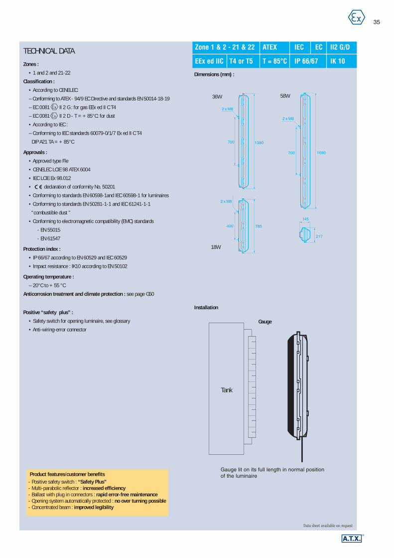
TECHNICAL DATA
Zones :
• 1 and 2 and 21-22
Classification :
• According to CENELEC:
– Conforming to ATEX - 94/9 EC Directive and standards EN 50014-18-19
– EC 0081 II 2 G : for gas EEx ed II C T4
– EC 0081 II 2 D - T = + 85°C: for dust
• According to IEC :
– Conforming to IEC standards 60079-0/1/7 Ex ed II C T4
DIP A21 TA = + 85°C
Approvals :
• Approved type Fle
• CENELEC LCIE 98 ATEX 6004
• IEC LCIE Ex 98.012
• declaration of conformity No. 50201
• Conforming to standards EN 60598-1and IEC 60598-1 for luminaires
• Conforming to standards EN 50281-1-1 and IEC 61241-1-1
“combustible dust ”
• Conforming to electromagnetic compatibility (EMC) standards
- EN 55015
- EN 61547
Protection index :
• IP 66/67 according to EN 60529 and IEC 60529
• Impact resistance : IK10 according to EN 50102
Operating temperature :
– 20°C to + 55 °C
Anticorrosion treatment and climate protection : see page G50
Positive “safety plus” :
• Safety switch for opening luminaire, see glossary
• Anti-wiring-error connector
35
Data sheet available on request
Dimensions (mm) :
Installation
Zone 1 & 2 - 21 & 22 ATEX IEC EC II2 G/D
EEx ed IIC T4 or T5 T = 85°C IP 66/67 IK 10
18W
36W
400
700
700
217
785
1390
1690
2 x M8
2 x M8
2 x M8
145
58W
Tank
Gauge
Gauge lit on its full length in normal position of the luminaireProduct features/customer benefits
- Positive safety switch : “Safety Plus”- Multi-parabolic reflector : increased efficiency- Ballast with plug in connectors : rapid error-free maintenance- Opening system automatically protected : no over turning possible- Concentrated beam : improved legibility
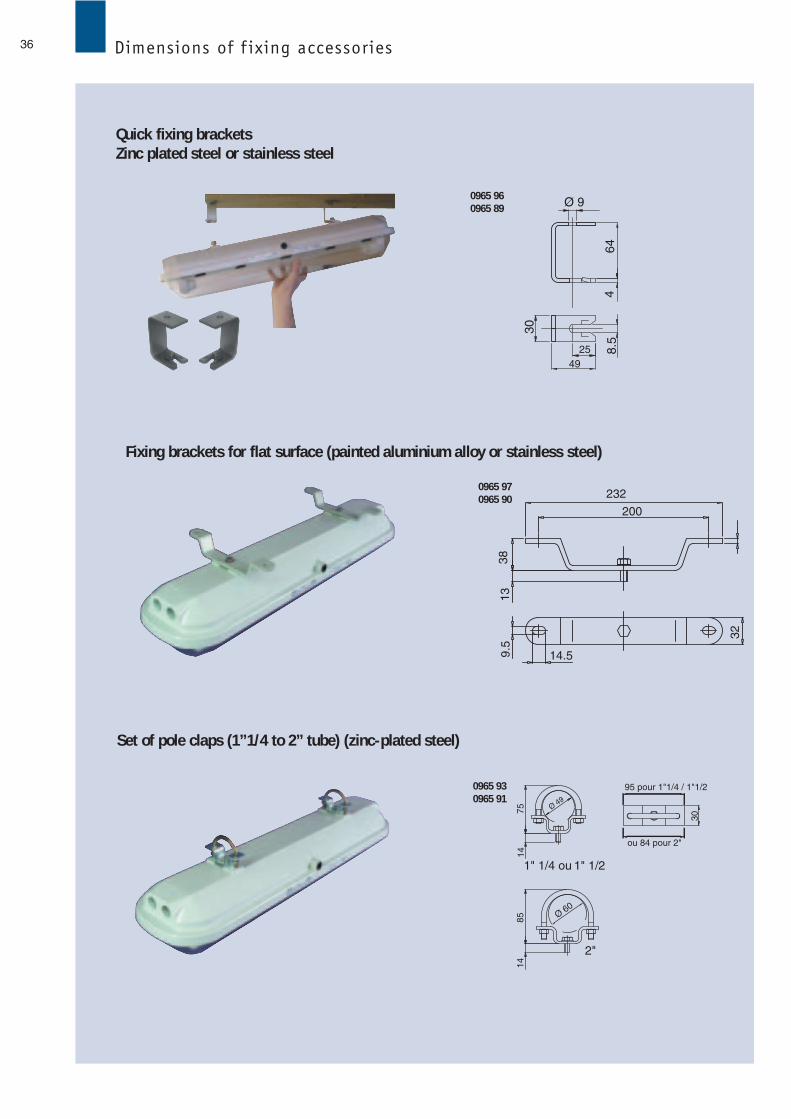
36 Dimensions of f ixing accessories
Ø 9
2549
8.5
464
30
232
200
14.59.5
1338
32
1" 1/4 ou 1" 1/2
2"
75
30
1414
85 Ø 60
Ø 49
ou 84 pour 2"
95 pour 1"1/4 / 1"1/2
0965 960965 89
0965 970965 90
0965 930965 91
Quick fixing bracketsZinc plated steel or stainless steel
Fixing brackets for flat surface (painted aluminium alloy or stainless steel)
Set of pole claps (1”1/4 to 2” tube) (zinc-plated steel)
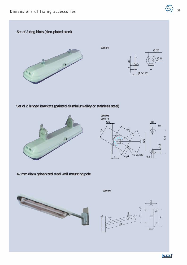
37Dimensions of f ixing accessories
Ø 20
Ø 8
M 8x1.25
3615
30
30
30
90
5.5
77
41
82
100
14.5
M 8X1.2513
132
1832
9.5
575
430
Ø 42
152
128
Ø 10.5
1214
0
Ø 20
200
0965 94
0965 980965 74
0965 95
Set of 2 hinged brackets (painted aluminium alloy or stainless steel)
Set of 2 ring blots (zinc-plated steel)
42 mm diam galvanized steel wall mounting pole
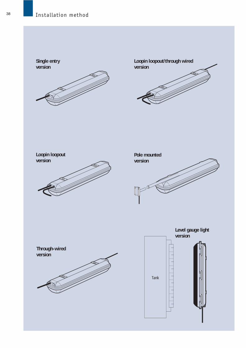
38 Installation method
Tank
Single entry version
Loopin loopoutversion
Through-wiredversion
Level gauge lightversion
Pole mounted version
Loopin loopout/through wiredversion

39
Data sheet available on request
Connection and wiring diagramm
Standard 3 phases Single phase loop-in loop-outSingle entry Loop-in Loop-out Through-wired through-wired
UNPE
UPE
N UN U
LN L
PE
N
PE
N
PE
VU
L1N L3L2
PE
L2L1
VU
N L3
PE
N
UNPEPE
NPE
UPE
N
L
PE
L'
N
N
PE
N
UPE
N
NPE
U U'N UPE
N UPE
N U U'PE
U'N
PE
N U'N U'PE
UPE
UU'PE
N
Type
Cableconnections
Standardand level gauge
lighting (1)
Emergency
Pole mountingversion
Emergencypole mounting
version
(1)
N LN N L L
N L L’ N L L’ N L L’ N L L’ N N L L L’ L’ L’ L’ N
N L
(2)
(2) 3 phases through-wired for balance load circuit
N L
L’ L N
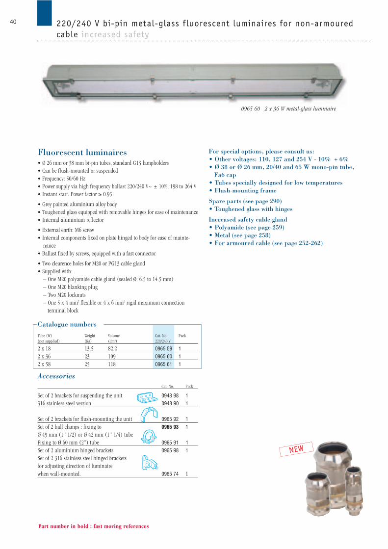
Fluorescent luminaires• Ø 26 mm or 38 mm bi-pin tubes, standard G13 lampholders• Can be flush-mounted or suspended• Frequency: 50/60 Hz• Power supply via high frequency ballast 220/240 V~ ± 10%, 198 to 264 V• Instant start. Power factor ≥ 0.95
• Grey painted aluminium alloy body• Toughened glass equipped with removable hinges for ease of maintenance• Internal aluminium reflector
• External earth: M6 screw• Internal components fixed on plate hinged to body for ease of mainte-
nance• Ballast fixed by screws, equipped with a fast connector
• Two clearence holes for M20 or PG13 cable gland • Supplied with:
– One M20 polyamide cable gland (sealed Ø: 6.5 to 14.5 mm) – One M20 blanking plug – Two M20 locknuts – One 5 x 4 mm2 flexible or 4 x 6 mm2 rigid maximum connection
terminal block
Catalogue numbersTube (W) Weight Volume Cat. No. Pack(not supplied) (Kg) (dm3) 220/240 V
2 x 18 13.5 82.2 0965 59 12 x 36 23 109 0965 60 12 x 58 25 118 0965 61 1
AccessoriesCat. No. Pack
Set of 2 brackets for suspending the unit 0948 98 1316 stainless steel version 0948 90 1
Set of 2 brackets for flush-mounting the unit 0965 92 1Set of 2 half clamps : fixing to 0965 93 1Ø 49 mm (1” 1/2) or Ø 42 mm (1” 1/4) tubeFixing to Ø 60 mm (2”) tube 0965 91 1Set of 2 aluminium hinged brackets 0965 98 1Set of 2 316 stainless steel hinged brackets for adjusting direction of luminaire when wall-mounted. 0965 74 1
For special options, please consult us: • Other voltages: 110, 127 and 254 V - 10% + 6%• Ø 38 or Ø 26 mm, 20/40 and 65 W mono-pin tube,
Fa6 cap • Tubes specially designed for low temperatures • Flush-mounting frame
Spare parts (see page 290)• Toughened glass with hinges
Increased safety cable gland• Polyamide (see page 259)• Metal (see page 258)• For armoured cable (see page 252-262)
40
Part number in bold : fast moving references
0965 60 2 x 36 W metal-glass luminaire
NEW
220/240 V bi-pin metal-glass f luorescent luminaires for non-armouredcable increased safety