easy saw - power tools plus
TRANSCRIPT

EASY SAW
054-8326-0
Owner’s Manual
PRODUCT SPECIFICATIONS
Rating: 120 V, 60 Hz AC
Amperes: 13 A
Blade speed: 4800 RPM (no load)
Blade: 7 ¼” (18.4 cm), 5/8” (15.9 mm) arbour, 40 Tungsten carbide teeth
Wood maximum cutting depth: 2 ½” (64 mm) @ 90° 1 13/16” (46 mm) @ 45°
Steel maximum thickness: 1/8" (3.2 mm)
Bevel angle: 0–50°
Weight: 13 lb 14 oz (6.3 kg)
Need Assistance? Call us on our toll free customer support line: 1-800-689-9928
Technical questions
Replacement parts Parts missing from package
Imported by Mastercraft Canada Toronto, Canada M4S 2B8

2
Product specifications ………….……………………………………………………. 1 Table of contents ……………………………………………………………………... 2 General safety warnings …………………………………………………………….. 3–4 Eye, ear & lung protection …………………………………………………………… 3–4 Electrical safety ………………………………………………………………………. 4 Power tool safety ……………………………………………………………………... 5–6 General safety rules ………………………………………………………………….. 5 Work area ………………………………………………………………….………….. 5 Electrical safety ………………………………………………………………………. 5 Personal safety ……………………………………………………………………….. 5–6 Use and care of power tools .……………………………………………………….. 6 Service ………………………………………………………………………………… 6 Specific safety rules ………………………………………………………………….. 7–9 Extension cord safety ………………………………………………………………... 10 Symbols ……………………………………………………………………………….. 11 Know your easy saw ……………………………………………………………… 12 Accessories …………………………………………………………………………… 13 Contents ………………………………………………………………………………. 13–15 Assembly and operating …………………………………………………………….. 16–33 Installing the track rider ……………………………………………………………… 16 Installing the metal cutting shield …………………………………………………… 16–17 Changing the blade …………………………………………………………………... 17–18 Setting the cutting depth …………………………………………………………….. 19 Bevel cutting angle …………………………………………………………………… 19–20 Installing the rip guide ……………………………………………………………….. 20 Vacuum port ………………………………………………………………………….. 20–21 Lock-off button ……………………………………………………………………….. 22 Trigger switch ………………………………………………………………………… 22 Laser switch …………………………………………………………………………... 22 Laser adjustment ……………………………………………………………………... 23 Resettable overload switch …………………………………………………………. 23 Materials you can cut ………………………………………………………………… 24 General cutting ……………………………………………………………………….. 24–25 Plunge cutting ………………………………………………………………………… 26 Metal cutting …………………………………………………………………………... 27 Cutting using the rip guide …………………………………………………………... 27 Assembling the guide track …………………………………………………………. 28–29 Cutting using the guide track ………………………………………………………... 30–31 Installing zero clearance inserts ……………………………………………………. 31–32 Maintenance ………………………………………………………………………….. 33–34 Replacing carbon motor brushes …………………………………………………… 33 General maintenance ………………………………………………………………... 34 Exploded view ………………………………………………………………………… 35–36 Parts list ……………………………………………………………………………….. 37–40 Warranty ……………………………………………………………………….……… 41–42
TABLE OF CONTENTS

3
EYE, EAR & LUNG PROTECTION
This instruction manual includes the following:
General Safety Rules
Specific Safety Rules and Symbols
Functional Description
Assembly
Operation
Maintenance
Accessories
!
ALWAYS WEAR EYE PROTECTION THAT CONFORMS WITH CSA
REQUIREMENTS or ANSI SAFETY STANDARD Z87.1
FLYING DEBRIS can cause permanent eye damage. Prescription
eyeglasses ARE NOT a replacement for proper eye protection.
WARNING: Non-compliant eyewear can cause serious injury if
broken during the operation of a power tool.
SAVE THESE INSTRUCTIONS FOR REFERENCE
WARNING: Use hearing protection, particularly during extended
periods of operation of the tool, or if the operation is noisy. !
GENERAL SAFETY WARNINGS
WARNING: Before using this tool or any of its accessories, read this
manual and follow all Safety Rules and Operating Instructions. The important precautions, safeguards and instructions appearing in this manual are not meant to cover all possible situations. It must be understood that common
sense and caution are factors which cannot be built into the product.
!

4
ELECTRICAL SAFETY
WARNING: To avoid electrical hazards, fire hazards or damage to the
tool, use proper circuit protection.
This tool is wired at the factory for 120 V AC operation. It must be
connected to a 120 V AC, 15 A circuit that is protected by a time-delayed
fuse or circuit breaker. To avoid shock or fire, replace power cord
immediately if it is worn, cut or damaged in any way.
GENERAL SAFETY WARNINGS
WEAR A DUST MASK THAT IS DESIGNED TO BE USED WHEN
OPERATING A POWER TOOL IN A DUSTY ENVIRONMENT.
WARNING: Dust that is created by power sanding, sawing, grinding,
drilling, and other construction activities may contain chemicals that are known to cause cancer, birth defects, or other genetic abnormalities. These chemicals include:
Lead from lead-based paints Crystalline silica from bricks, cement, and other masonry products Arsenic and chromium from chemically treated lumber
The level of risk from exposure to these chemicals varies, according to how
often this type of work is performed. In order to reduce exposure to these
chemicals, work in a well-ventilated area, and use approved safety
equipment, such as a dust mask that is specifically designed to filter out
microscopic particles.
!
SAVE THESE INSTRUCTIONS FOR REFERENCE

5
WARNING Read all safety warnings and instructions. Failure to follow the
warnings and instructions may result in electric shock, fire and/or serious injury. Save all warnings and instructions for future reference.
Work area safety
Keep work area clean and well lit.
Cluttered or dark areas invite accidents. Do not operate power tools in explosive atmospheres, such as in the presence of flammable liquids, gases or dust.
Power tools create sparks which may ignite the dust or fumes. Keep children and bystanders away while operating a power tool.
Distractions can cause you to lose control. Electrical safety
Power tool plugs must match the outlet. Never modify the plug in any way. Do not use any adapter plugs with earthed (grounded) power tools. Unmodified
plugs and matching outlets will reduce risk of electric shock.
Avoid body contact with earthed or grounded surfaces such as pipes, radiators, ranges and refrigerators.
There is an increased risk of electric shock if your body is earthed or grounded.
Do not expose power tools to rain or wet conditions. Water entering a power
tool will increase the risk of electric shock.
Do not abuse the cord. Never use the cord for carrying, pulling or unplugging the power tool. Keep cord away from heat, oil, sharp edges or moving parts.
Damaged or entangled cords increase the risk of electric shock. When operating a power tool outdoors, use an extension cord suitable for outdoor use. Use of a cord suitable for
outdoor use reduces the risk of electric shock.
If operating a power tool in a damp location is unavoidable, use a residual current device (RCD) protected supply.
Use of a ground fault circuit interrupter (GFCI) reduces the risk of electric shock. Personal safety
Stay alert, watch what you are doing and use common sense when operating a power tool. Do not use a power tool while you are tired or under the influence of drugs, alcohol or medication. A moment of inattention while
operating power tools may result in serious personal injury. Use personal protective equipment. Always wear eye protection. Protective
equipment such as dust mask, non-skid safety shoes, hard hat, or hearing protection used for appropriate conditions will reduce personal injuries.
Prevent unintentional starting. Ensure the switch is in the off-position before connecting to power source and/or battery pack, picking up or carrying the tool. Carrying power tools with your finger
on the switch or energising power tools that have the switch on invites accidents. Remove any adjusting key or wrench before turning the power tool on. A
wrench or a key left attached to a rotating part of the power tool may result in personal injury.
POWER TOOL SAFETY
!

6
PERSONAL SAFETY – cont’d
Do not overreach. Keep proper footing and balance at all times. This enables
better control of the power tool in unexpected situations.
Dress properly. Do not wear loose clothing or jewellery. Keep your hair, clothing and gloves away from moving parts. Loose clothes, jewellery or long hair
can be caught in moving parts.
If devices are provided for the connection of dust extraction and collection facilities, ensure these are connected and properly used. Use of
dust collection can reduce dust-related hazards. Power tool use and care
Do not force the power tool. Use the correct power tool for your application.
The correct power tool will do the job better and safer at the rate for which it was designed.
Do not use the power tool if the switch does not turn it on and off. Any power
tool that cannot be controlled with the switch is dangerous and must be repaired.
Disconnect the plug from the power source and/or the battery pack from the power tool before making any adjustments, changing accessories, or storing power tools. Such preventive
safety measures reduce the risk of starting the power tool accidentally. Store idle power tools out of the reach of children and do not allow persons unfamiliar with the power tool or these instructions to operate the power tool.
Power tools are dangerous in the hands of untrained users.
Maintain power tools. Check for misalignment or binding of moving parts, breakage of parts and any other condition that may affect the power tool’s operation. If damaged, have the power tool repaired before use. Many
accidents are caused by poorly maintained power tools.
Keep cutting tools sharp and clean.
Properly maintained cutting tools with sharp cutting edges are less likely to bind and are easier to control.
Use the power tool, accessories and tool bits etc. in accordance with these instructions, taking into account the working conditions and the work to be performed. Use of the power tool for
operations different from those intended could result in a hazardous situation. Service
Have your power tool serviced by a qualified repair person using only identical replacement parts. This will
ensure that the safety of the power tool is maintained.
POWER TOOL SAFETY
7
WARNING: Know your circular
saw. Do not plug the tool into the power source until you have read and understand this Instruction Manual. Learn the tool’s applications and limitations, as well as the specific potential hazards related to this tool.
Following this rule will reduce the risk of electric shock, fire, or serious injury.
Always wear eye protection. Any power tool can throw foreign objects into your eyes and cause permanent eye
damage. ALWAYS wear safety goggles (not glasses) that comply with ANSI safety standard Z87.1. Everyday glasses have only impact resistant lenses. They ARE NOT safety glasses.
WARNING: Glasses or goggles
not in compliance with ANSI Z87.1 could cause serious injury when they break.
Always keep hands out of the path of the saw blade. Avoid awkward hand positions where a sudden slip could cause your hand to move into the path of the saw blade.
DANGER: Keep hands away from cutting area and the blade. Keep your second hand on the tool. If both hands
are holding the saw, they cannot be cut by the blade. Do not reach underneath the workpiece.
The guard cannot protect you from the blade below the workpiece.
Adjust the cutting depth according to the thickness of the workpiece. Less
than a full tooth of the blade teeth should be visible below the workpiece or approximately 3/8" (10 mm). Never hold piece being cut in your hands or across your leg. Secure the workpiece to a stable platform. It is
important to support the work properly to minimize body exposure, blade binding, or loss of control. Hold power tool by insulated gripping surfaces when performing an operation where the cutting tool may contact hidden wiring or its own cord. Contact
with a “live” wire will also make exposed metal parts of the power tool “live” and shock the operator. When ripping always use a straight rip guide. This improves the accuracy of cut
and reduces the chance of the blade binding. Always use blades with correct size and shape (diamond versus round) of arbour holes. Blades that do not match
the mounting hardware of the saw will run eccentrically, causing loss of control. Never use damaged or incorrect blade washers or bolt. The blade washers and
bolt were specially designed for your saw, for optimum performance and safety of operation.
!
!
SAVE THESE INSTRUCTIONS FOR REFERENCE
!
SPECIFIC SAFETY RULES
8
CAUSES AND OPERATOR PREVENTION OF KICKBACK
Kickback is a sudden reaction to a pinched, bound or misaligned saw blade, causing an uncontrolled saw to lift up and out of the workpiece toward the operator. When the blade is pinched or bound tightly by the kerf closing down, the blade stalls and the motor reaction drives the unit rapidly back toward the operator. If the blade becomes twisted or misaligned in the cut, the teeth at the back edge of the blade can dig into the top surface of the wood causing the blade to climb out of the kerf and jump back toward the operator. Kickback is the result of saw misuse and/or incorrect operating procedures or conditions and can be avoided by taking proper precautions as given below: Maintain a firm grip with both hands on the saw and position your arms to resist kickback forces. Position your body to the left or right side of the blade, but not in line with the blade.
Kickback could cause the saw to jump backwards, but kickback forces can be controlled by the operator, if proper precautions are taken. When the blade is binding, or when interrupting a cut for any reason, release the trigger and hold the saw motionless in the material until the blade comes to a complete stop. Never attempt to remove the saw from the work or pull the saw backward while the blade is in motion or kickback may occur. Investigate and take corrective
actions to eliminate the cause of blade binding.
When restarting a saw in the workpiece, centre the saw blade in the kerf and check that saw teeth are not engaged into the material. If the saw blades are
binding, it may walk up or kickback from the workpiece as the saw is restarted. Support large panels to minimize the risk of blade pinching and kickback.
Large panels tend to sag under their own weight. Supports must be placed under the panel on both sides, near the line of cut and near the edge of the panel. Do not use dull or damaged blades.
Unsharpened or improperly set blades produce narrow kerf causing excessive friction, blade binding and kickback. ADDITIONAL SPECIFIC SAFETY RULES Use extra caution when making a “plunge cut” into existing walls or other blind areas. The protruding blade may cut
objects that can cause kickback. Check the lower guard for proper closing before each use. Do not operate the saw if the lower guard does not move freely and close instantly. Never clamp or tie the lower guard into the open position. If the saw is accidentally
dropped, the lower guard may be damaged. Raise the lower guard with the retracting handle and make sure it moves freely and does not touch the blade or any other part in all depths of cuts. Check the operation of the lower guard spring. If the guard and the spring are not operating properly, they must be serviced before use. The lower guard
may operate sluggishly due to damaged parts, gummy deposits, or a build-up of debris.
SPECIFIC SAFETY RULES
SAVE THESE INSTRUCTIONS FOR REFERENCE
9
ADDITIONAL SPECIFIC SAFETY RULES – cont’d The lower guard should be retracted manually only for special cuts such as “plunge cuts” and “compound cuts”. Raise lower guard by retracting handle and as soon as the blade enters the material, the lower guard must be released. For all other sawing, the lower
guard should operate automatically. Always observe that the lower guard is covering the blade before placing saw down on the bench or on the floor. An
unprotected, coasting blade will cause the saw to walk backwards, cutting whatever is in its path. Be aware of the time it takes for the blade to stop after the switch is released. Never operate the saw while it is being carried to another location. The blade guard may be open and potentially cause serious injury. If the switch fails to turn the saw ON or OFF properly, stop using it immediately and have the saw switch repaired. Always allow the saw to reach full speed before beginning the cut. Never use the side of the blade for cutting. When making horizontal cuts, make sure the weight of the tool is not forcing the side of the blade to do the cutting. This will reduce the risk of kickback. Make sure there are no nails or foreign objects in the area of the workpiece to be cut. Never lay workpiece on hard surfaces like concrete, stone, etc. The protruding
blade may cause the tool to jump.
DANGER: To avoid injury from
accidental starting, always remove the plug from the power source before making any adjustments and before installing or removing a saw blade. When replacing the blade, make sure the replacement blade is 7¼ " (18.4 cm) in diameter and is rated for at least 7,000 RPM. Installing an incorrect
blade will result in possible injury and poor cutting action. After changing a blade or making adjustments, make sure the blade clamp screw is securely tightened.
Loose blades and adjustment devices will be violently thrown. Never touch the blade during or immediately after use. After use the
blade is too hot to be safely touched with bare hands.
DANGER: Never use the laser in the
presence of small children. Small children may stare directly into the laser light beam and cause serious eye injury.
DANGER: The laser light beam that
is projected from the front of the laser level can be dangerous to eyesight. Never allow anyone to stare directly into the light. Staring directly into the light beam may result in serious eye damage.
DANGER: Always remove the plug
from the power source when changing the
blade.
SPECIFIC SAFETY RULES
!
!
!
!
SAVE THESE INSTRUCTIONS FOR REFERENCE

10
WARNING: Keep the extension
cord clear of the working area. Position
the cord so it will not get caught on the
workpiece, tools or any other obstructions
while you are working with the power tool.
Make sure any extension cord used with
this tool is in good condition. When using
an extension cord, be sure to use one of
heavy enough gauge to carry the current
the tool will draw. An undersized cord will
cause a drop in line voltage resulting in
loss of power and overheating.
The table at right shows the correct size to
use according to cord length and
nameplate ampere rating. If in doubt, use
the next heavier gauge. The smaller the
gauge number the heavier the cord.
Be sure your extension cord is properly
wired and in good condition. Always
replace a damaged extension cord or have
it repaired by a qualified electrician before
using it. Protect your extension cord from
sharp objects, excessive heat and damp or
wet areas.
Use a separate electrical circuit for your
power tools. This circuit must not be less
than 14 gauge wire and should be
protected with either a 15 A time delayed
fuse or circuit breaker. Before connecting
the power tool to the power source, make
sure the switch is in the OFF position and
the power source is the same as indicated
on the nameplate. Running at lower
voltage will damage the motor.
! MINIMUM GAUGE (AWG)
EXTENSION CORDS (120 V use only)
Amperage rating
Total length
More than
Not more than
25' (7.5 m)
50' (15 m)
100' (30 m)
150' (45 m)
0 6 18 16 16 14
6 10 18 16 14 12
10 12 16 16 14 12
12 16 14 12 Not Applicable
EXTENSION CORD SAFETY
SAVE THESE INSTRUCTIONS FOR REFERENCE

11
V Volts
A Amperes
Hz Hertz
W Watts
kW Kilowatts
Microfarads
L Litres
kg Kilograms
H Hours
N/cm2 Newtons per square centimetre
Pa Pascals
Min Minutes
S Seconds
Alternating current
Three-phase alternating current
Three-phase alternating current with neutral
Direct current
No load speed
Alternating or direct current
Class II construction
Splash-proof construction
Watertight construction
Protective grounding at grounding terminal, Class I tools
Revolutions or reciprocations per minute
Diameter
Off position
Arrow
Warning symbol
Warning, bright light
SYMBOLS
WARNING: Some of the following symbols may appear on the easy
saw. Study these symbols and learn their meaning. Proper interpretation of
these symbols will allow for more efficient and safer operation of this tool.
!
This symbol designates that this tool is
listed with both Canadian and U.S.
requirements by Underwriters
Laboratories.
Conforms to UL Std. 60745-1& 60745-2-5.
Certified to CAN/CSA Std. C22.2 No.
60745-1 & 60745-2-5.
HOMOLOGUE
61TN E213739

12
Rip guide
Guide track (not exactly as illustrated)
KNOW YOUR EASY SAW
ON/OFF Trigger switch
Laser ON/OFF button
Lock-off button
Vacuum port
Vacuum port baffle
Laser adjustment screw
Brush cap
Sole plate
45° & 0° cutting marks
Bevel cutting adjustment lever
Rip guide adjustment knob
Depth adjustment stop button
Main handle
Front handle
Blade guard lever

13
AVAILABLE ACCESSORIES
WARNING: Use only accessories
that are recommended for this easy saw. Follow the instructions that accompany the accessories. The use of improper accessories may result in injury to the operator or damage to the tool.
Before using any accessory, carefully read the instructions or the owner’s manual for the accessory. Saw blades
WARNING: If any part is missing or
damaged, do not plug the tool into the power source or install any accessory until the missing or damaged part is replaced.
CONTENTS
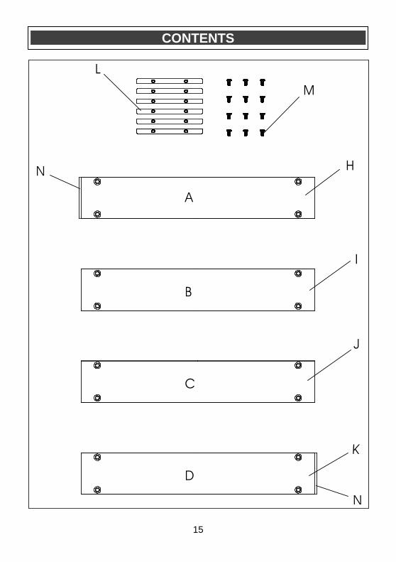
Carefully unpack the easy saw. Compare the contents against the “EASY SAW COMPONENTS” and “GUIDE TRACK COMPONENTS” charts below. NOTE: See illustrations of the easy saw
components on Pages 14 & 15.
WARNING: To avoid fire or toxic
reaction, never use gasoline, naphtha, acetone, lacquer thinner or similar highly volatile solvents to clean the tool.
CONTENTS
EASY SAW COMPONENTS
KEY DESCRIPTION QTY
A Easy saw 1
B 5 mm Hex key 1
C 40 T blade 1
D Rip guide 1
E Track rider 1
F Zero clearance insert 3
G Metal cutting shield 1
Owner’s Manual 1
!
ACCESSORIES
!
!
GUIDE TRACK COMPONENTS
KEY DESCRIPTION QTY
H Track section “A” 1
I Track section “B” 1
J Track section “C” 1
K Track section “D” 1
L Joining bars 6
M Screws 12
N End caps (preassembled)
2

14
CONTENTS
15
CONTENTS
16
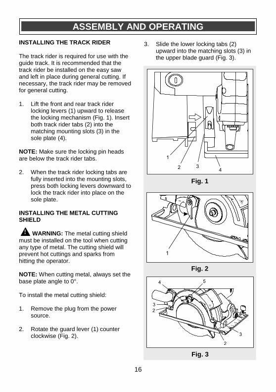
INSTALLING THE TRACK RIDER
The track rider is required for use with the guide track. It is recommended that the track rider be installed on the easy saw and left in place during general cutting. If necessary, the track rider may be removed for general cutting. 1. Lift the front and rear track rider
locking levers (1) upward to release the locking mechanism (Fig. 1). Insert both track rider tabs (2) into the matching mounting slots (3) in the sole plate (4).
NOTE: Make sure the locking pin heads
are below the track rider tabs. 2. When the track rider locking tabs are
fully inserted into the mounting slots, press both locking levers downward to lock the track rider into place on the sole plate.
INSTALLING THE METAL CUTTING SHIELD
WARNING: The metal cutting shield
must be installed on the tool when cutting any type of metal. The cutting shield will prevent hot cuttings and sparks from hitting the operator. NOTE: When cutting metal, always set the
base plate angle to 0°. To install the metal cutting shield: 1. Remove the plug from the power
source.
2. Rotate the guard lever (1) counter clockwise (Fig. 2).
3. Slide the lower locking tabs (2)
upward into the matching slots (3) in the upper blade guard (Fig. 3).
ASSEMBLY AND OPERATING
Fig. 1
Fig. 2
Fig. 3
!
17
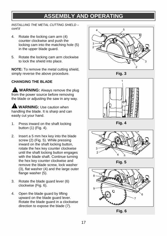
INSTALLING THE METAL CUTTING SHIELD – cont’d
4. Rotate the locking cam arm (4) counter clockwise and push the locking cam into the matching hole (5) in the upper blade guard.
5. Rotate the locking cam arm clockwise to lock the shield into place.
NOTE: To remove the metal cutting shield,
simply reverse the above procedure. CHANGING THE BLADE
WARNING: Always remove the plug
from the power source before removing the blade or adjusting the saw in any way.
WARNING: Use caution when
handling the blade. It is sharp and can easily cut your hand.
1. Press inward on the shaft locking button (1) (Fig. 4).
2. Insert a 5 mm hex key into the blade screw (2) (Fig. 5). While pressing inward on the shaft locking button, rotate the hex key counter clockwise until the shaft locking button engages with the blade shaft. Continue turning the hex key counter clockwise and remove the blade screw, lock washer (3), flat washer (4) and the large outer flange washer (5).
3. Rotate the blade guard lever (6) clockwise (Fig. 6).
4. Open the blade guard by lifting upward on the blade guard lever. Rotate the blade guard in a clockwise direction to expose the blade (7).
!
ASSEMBLY AND OPERATING
Fig. 3
Fig. 5
ASSEMBLY AND OPERATING
!
Fig. 4
Fig. 6

18
CHANGING THE BLADE – cont’d
5. While holding the blade guard lever in
the open position, lift the blade off the shaft (8) and slide it out through the slot in the sole plate (9).
NOTE: Do NOT remove the inner large
flange washer. 6. To place a new blade onto the motor
shaft, rotate the blade guard forward (Fig. 6) and slide the blade through the slot in the sole plate until it fits over the motor shaft.
NOTES:
a) Make sure the blade teeth are pointing forward at the bottom of the blade. b) Make sure the hole in the blade is placed over the matching boss on the inner large flange washer. 7. Place the large outer flange washer
onto the motor shaft.
NOTE: Make sure the flat sections of the
large outer flange washer fit over the matching flat sections on the motor shaft. 8. Insert the blade screw through the
lock washer, flat washer and the large outer flange washer and thread it clockwise into the end of the motor shaft.
9. Lock the motor shaft using the shaft locking button and firmly tighten the blade screw using the hex key.
NOTE: Make sure the screw is NOT cross-
threaded and that the blade does not wobble when turned by hand.
ASSEMBLY AND OPERATING
Fig. 6
ASSEMBLY AND OPERATING
19
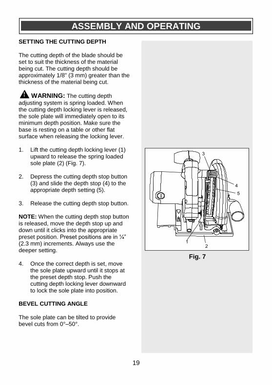
SETTING THE CUTTING DEPTH
The cutting depth of the blade should be set to suit the thickness of the material being cut. The cutting depth should be approximately 1/8" (3 mm) greater than the thickness of the material being cut.
WARNING: The cutting depth
adjusting system is spring loaded. When the cutting depth locking lever is released, the sole plate will immediately open to its minimum depth position. Make sure the base is resting on a table or other flat surface when releasing the locking lever. 1. Lift the cutting depth locking lever (1)
upward to release the spring loaded sole plate (2) (Fig. 7).
2. Depress the cutting depth stop button (3) and slide the depth stop (4) to the appropriate depth setting (5).
3. Release the cutting depth stop button. NOTE: When the cutting depth stop button
is released, move the depth stop up and down until it clicks into the appropriate preset position. Preset positions are in ¼” (2.3 mm) increments. Always use the deeper setting. 4. Once the correct depth is set, move
the sole plate upward until it stops at the preset depth stop. Push the cutting depth locking lever downward to lock the sole plate into position.
BEVEL CUTTING ANGLE
The sole plate can be tilted to provide bevel cuts from 0°–50°.
ASSEMBLY AND OPERATING
Fig. 7
!

20
BEVEL CUTTING ANGLE– cont’d
Adjusting the sole plate angle 1. Loosen the bevel adjustment by lifting
upward on the bevel gauge adjustment lever (1) (Fig. 8).
2. Rotate the sole plate (2) to the desired angle as shown on the bevel gauge (3).
3. Press downward on the bevel gauge adjustment lever to lock the sole plate into position.
INSTALLING THE RIP GUIDE
1. Loosen the rip guide adjusting knob
(1) (Fig. 9).
2. Slide the rip guide rod (2) into the rip
guide slot (3). Continue to slide the
guide rod across the sole plate and
into the adjusting knob slot (4) on the
opposite side of the sole plate.
3. Adjust the rip guide shoe (5) to the correct distance from the blade and tighten the rip guide adjusting knob.
NOTE: The rip guide may be installed from
the opposite side, but the rip guide rod MUST engage both of the rip guide slots in the sole plate. VACUUM PORT
A workshop vacuum can be attached to the vacuum port to extract much of the dust that is created while cutting wood. When using a workshop vacuum, pull the vacuum port baffle tab (1) upward until the hole in the baffle engages with the matching pin (2) in the upper blade guard (Fig. 10).
ASSEMBLY AND OPERATING
Fig. 10
Fig. 8
Fig. 9

21
VACUUM PORT – cont’d
NOTE: When cutting wood without using
the workshop vacuum, the vacuum port baffle should be closed to limit the amount of sawdust being exhausted toward the operator.
WARNING: The vacuum port baffle
MUST be in the closed position when cutting metal to prevent hot cuttings from hitting the operator.
WARNING: Never attach a
workshop vacuum to the vacuum port when cutting metal. The cuttings will be hot and may cause a fire in the workshop vacuum.
ASSEMBLY AND OPERATING
For safety reasons, the operator must read the sections of this Owner’s Manual entitled “GENERAL SAFETY WARNINGS”, “POWER TOOL SAFETY”, “SPECIFIC SAFETY RULES”, “EXTENSION CORD SAFETY” and “SYMBOLS” before using this easy saw. Verify the following every time the easy saw is used: 1. Safety glasses, safety goggles, or
face shield are being worn. 2. Hearing protection is being worn. 3. The blade is in good condition. 4. The metal cutting shield is
installed before cutting metal. 5. All adjustment devices are tight
and any accessory is properly tightened into the accessory holder of the tool.
Failure to observe these safety rules will significantly increase the risk of
injury.
WARNING !
!
!

22
LOCK-OFF BUTTON
The lock-off button (1) is a safety device designed to reduce the possibility of accidentally starting the saw (Fig. 11). This button must be depressed before the trigger switch (2) can be depressed. NOTE: The lock-off button can be
depressed either left or right. TRIGGER SWITCH
1. To turn the saw ON, depress the lock-
off button with your thumb.
2. While holding the lock-off button in the depressed position, squeeze the trigger switch to start the saw.
3. Once the saw starts, release the lock-off button. The saw will remain running until the trigger switch is released.
4. To turn the saw OFF, release the trigger switch.
NOTE: The lock-off button will have to be
depressed again to restart the saw. LASER SWITCH
This saw is equipped with a laser guidance system for more precise cutting.
DANGER: Never allow the laser
beam to shine into a person’s eyes. Serious eye damage could result.
To turn the laser ON, press the laser switch (1) once (Fig. 12). To turn the laser OFF, press the laser switch again.
ASSEMBLY AND OPERATING
Fig. 11
Fig. 12
!

23
LASER ADJUSTMENT
The laser guide line should be centered in
the 0° cutting groove (1) (Fig. 13). If the
laser guide line is not correctly centered it
can be centered using a 5/64” (2 mm) slot
screwdriver.
Moving the laser line to the right
1. Turn the right laser adjustment screw
(2) counter clockwise ¼ turn.
2. Turn the left laser adjustment screw
clockwise ¼ turn.
3. Repeat steps #1 and #2 until the laser
guide line is moved to the correct
location.
Moving the laser line to the left
4. Turn the left laser adjustment screw
counter clockwise ¼ turn.
5. Turn the right laser adjustment screw
clockwise ¼ turn.
6. Repeat steps #4 and #5 until the laser guide line is moved to the correct location.
RESETTABLE OVERLOAD SWITCH
To avoid damaging the tool due to overloading, the overload switch will automatically turn the tool OFF when it senses an overloaded condition. When the switch turns the tool OFF, the overload button (1) will pop out (Fig. 14). When this condition happens, simply wait approximately one minute and press the overload switch button inward. Once reset, the tool will operate normally.
Fig. 13
ASSEMBLY AND OPERATING
Fig. 14

24
MATERIALS YOU CAN CUT
The easy saw is a versatile saw that allows you to cut many different types of materials. Some of the materials include: ● Wood products such as lumber,
hardwood, plywood, composition board and panelling
● Drywall ● Masonite and plastic This circular saw will also cut steel plate up to 1/8” (3.2 mm) thick, aluminum and non-ferrous metals. NOTE: There are several different types of
blades available. Generally, blades with carbide-tipped teeth cut better and stay sharp longer. Tooth count and configuration are also important. High tooth counts cut slower and are best suited for making smooth cuts on thinner materials such as panelling. Use the correct blade for your application. GENERAL CUTTING
NOTE: Always make a test cut on a scrap
workpiece to verify that all settings are correct. 1. Make any adjustments to the saw
before plugging it into the power source. Adjustments include cutting depth, bevel cutting angle and rip guide (if installed).
2. Clearly mark the workpiece to locate the position of the cut.
3. Hold a smaller workpiece with a vise. Clamp a larger workpiece to a work bench or table.
ASSEMBLY AND OPERATING

25
GENERAL CUTTING – cont’d
DANGER: Any workpiece that is not adequately clamped in place or properly supported for cutting may come loose or jamb the blade, causing serious injury. Never hold the workpiece in your hand.
4. Make sure there are no nails, screws,
clamps or foreign materials in the path of the saw blade.
5. Turn the laser ON.
6. Place the front edge of the sole plate on the workpiece.
7. With both hands firmly gripping the
saw, and with the blade NOT in contact with the surface to be cut, start the saw by depressing the lock-off button and then the trigger switch.
8. Once the saw has reached full speed,
gradually bring the moving blade into contact with the workpiece at the appropriate location.
NOTE: To align the saw blade with the
cutting mark, use the guide marks on the front of the sole plate (Fig. 15). Use the 0° cutting mark (1) and the laser line (2) for right angle cuts. Use only the 45° mark (3) for 45° bevel cuts. The 45° mark will allow for the extra material needed for the angle cut. Always make a test cut on a scrap workpiece before cutting the new material.
WARNING: Do not force the circular saw. Use only enough force to keep the blade cutting at full speed. Excessive pressure on the blade will cause it to slow down and overheat, resulting in poor cut quality and damage to the motor.
!
ASSEMBLY AND OPERATING
Fig. 15
!

26
PLUNGE CUTTING
WARNING: To avoid loss of
control, damage to the blade or damage to the workpiece, always use extreme caution when making plunge cuts. It is not recommended to plunge cut any material other than wood.
1. To plunge cut inside the edges of a
workpiece, clearly mark the cutting line on the workpiece.
2. Set the depth stop (Fig. 7) and set the bevel angle at 0° (Fig. 8). Do NOT lock the depth stop locking lever.
3. Set the saw on the workpiece so the sole plate is flat on the workpiece (Fig. 16).
4. Open the blade guard by rotating the blade guard lever (1) forward.
5. Align the saw blade with the cutting line (2) using the 0° cutting mark on the sole plate and the laser line.
NOTE: Make sure the saw blade is inside
the area to be cut out. 6. Start the saw and slowly lower the
blade onto the workpiece while holding the blade guard lever forward to allow the blade to cut into the workpiece (Fig. 17). Allow the blade to cut through the wood.
7. Continue lowering the blade into the workpiece until the full cutting depth has been achieved. Continue sawing toward the cutting line and complete the cut as required.
!
ASSEMBLY AND OPERATING
Fig. 16
Fig. 17

27
METAL CUTTING
Several types of metal can be cut with your easy saw. NOTES:
a. Use only the 40 tooth blade supplied with the tool to cut metal
b. Only cut aluminum, copper and steel c. Do NOT attempt to cut metals thicker
than 1/8” (3.2 mm). Thicker metals may overheat the blade.
WARNING: Metal cutting shield
must be installed. Never allow bystanders or pets to be in front of the easy saw when cutting metal. Hot sparks can injure bystanders.
When cutting any kind of material, be careful not cut a curve. Do not force the blade. If the blade chatters or vibrates
excessively, reduce the travel speed of the blade into the workpiece. Clamp all work firmly and saw as close as possible to the clamping point to eliminate any vibration of the work being cut. When cutting conduit, pipe or angle iron, clamp the workpiece in a vice if possible and saw close to the vice. To cut thin sheet materials, “sandwich” the material between hardboard or plywood and clamp the layers to eliminate material vibration and tearing. By doing this, the material will be cut smoothly. Lay out your pattern or cutting lines on top of the “sandwich”. CUTTING USING THE RIP GUIDE
Whenever possible, install the rip guide on the right hand side of the sole plate (Fig. 18). This will place the majority of the tool weight on the larger portion of the workpiece, making it easier to control the tool. If necessary, the rip guide may be installed from the opposite side, but the rip guide rod MUST engage both of the rip guide slots in the sole plate.
ASSEMBLY AND OPERATING
!
Fig. 18

28
ASSEMBLING THE GUIDE TRACK
The aluminum guide track is used in conjunction with the easy saw to make precise cuts across a workpiece up to 39” (1 m) wide. The guide track is shipped in four sections. To assemble the guide track, you will need a table or work bench at least 4’ (1.2 m) long. Assemble the guide track as follows: 1. Lay the left track section marked “A”
(1) on its back toward the left hand side of the work surface (Fig. 19).
2. Insert two joining bars (2) into the matching cavities (3) in the left hand track section “A” and fasten in place using two screws (4) (Fig. 20).
NOTE: Do not tighten any screws until the
guide track has been fully assembled (step #8). 3. Lay the second track section marked
“B” (5) on its back (Fig. 21). Slide the cavities over the two joining bars that are protruding from track section (A) and fasten in place using two screws (4).
4. Insert two joining bars into the matching cavities in the right hand end of track section “B” and fasten in place using two screws (Fig. 22).
ASSEMBLY AND OPERATING
Fig. 19
Fig. 20
Fig. 21
Fig. 22

29
ASSEMBLING THE GUIDE TRACK – cont’d 5. Lay the third track section marked “C”
(6) on its back (Fig. 23). Slide the cavities over the two joining bars that are protruding from the right hand end of track section “B” and fasten in place using two screws (4).
6. Insert two joining bars into the matching cavities in the right hand end of track section “C” and fasten in place using two screws (Fig. 24).
7. Lay the fourth track section marked “D” (7) on its back (Fig. 25). Slide the cavities over the two joining bars that are protruding from the right hand end of track section “C” and fasten in place using two screws (4).
8. Once all track sections are assembled, tighten all 12 screws.
NOTE: It is important to ensure that the
fully assembled guide track forms a straight line for cutting. Turning the guide track assembly on its edge on a flat table or workbench will help in aligning all four sections as they are tightened. Once all screws are fully tightened, recheck the assembly with a straight edge. Loosen and retighten the screws as required to properly align all sections of the guide track assembly.
ASSEMBLY AND OPERATING
Fig. 23
Fig. 24
Fig. 25
30
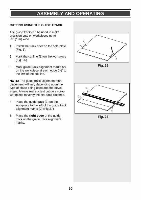
CUTTING USING THE GUIDE TRACK
The guide track can be used to make precision cuts on workpieces up to 39” (1 m) wide. 1. Install the track rider on the sole plate
(Fig. 1). 2. Mark the cut line (1) on the workpiece
(Fig. 26).
3. Mark guide track alignment marks (2) on the workpiece at each edge 5½” to the left of the cut line.
NOTE: The guide track alignment mark
placement will vary depending upon the type of blade being used and the bevel angle. Always make a test cut on a scrap workpiece to verify the set-back distance. 4. Place the guide track (3) on the
workpiece to the left of the guide track alignment marks (2) (Fig 27).
5. Place the right edge of the guide
track on the guide track alignment marks.
ASSEMBLY AND OPERATING
Fig. 26
Fig. 27
31
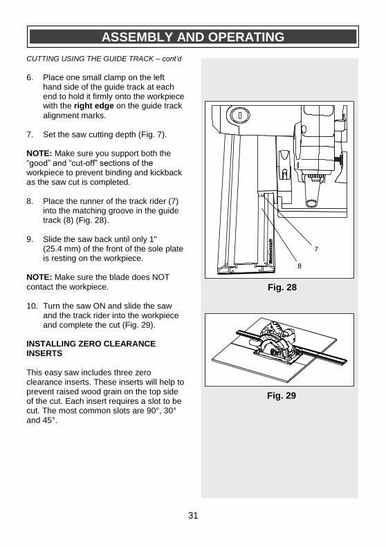
CUTTING USING THE GUIDE TRACK – cont’d 6. Place one small clamp on the left
hand side of the guide track at each end to hold it firmly onto the workpiece with the right edge on the guide track
alignment marks.
7. Set the saw cutting depth (Fig. 7).
NOTE: Make sure you support both the
“good” and “cut-off” sections of the workpiece to prevent binding and kickback as the saw cut is completed. 8. Place the runner of the track rider (7)
into the matching groove in the guide track (8) (Fig. 28).
9. Slide the saw back until only 1" (25.4 mm) of the front of the sole plate is resting on the workpiece.
NOTE: Make sure the blade does NOT
contact the workpiece. 10. Turn the saw ON and slide the saw
and the track rider into the workpiece and complete the cut (Fig. 29).
INSTALLING ZERO CLEARANCE INSERTS
This easy saw includes three zero clearance inserts. These inserts will help to prevent raised wood grain on the top side of the cut. Each insert requires a slot to be cut. The most common slots are 90°, 30° and 45°.
ASSEMBLY AND OPERATING
Fig. 28
Fig. 29

32
INSTALLING ZERO CLEARANCE INSERTS – cont’d
To install a zero clearance insert: 1. Release the depth adjustment lever to
allow the sole plate to completely clear the saw blade.
2. Place the insert tabs (1) into the four slots (2) in the under side of the sole plate (3) (Fig. 30).
3. While pressing the insert into the mounting slots, slide it toward the front of the sole plate.
NOTE: The insert will snap into place
when it is slid toward the front of the sole plate. 4. Set the depth stop to the desired
depth of cut (Fig. 7) and the bevel angle to the desired angle (Fig. 8).
5. Using a scrap workpiece that is THICKER than the depth setting, turn the saw ON and make a plunge cut to the preset depth (Fig. 16 & 17).
NOTE: The plunge cut will allow the blade
to make a precise cut in the insert, leaving very little clearance between the blade and the slot in the insert. 6. Turn the saw OFF and remove the
insert. It is important to mark the cut angle and depth on the upper side of the insert with a felt marker for future reference.
NOTE: To remove the insert, push a
medium sized flat blade screwdriver into the slot at the tab (4) (Fig. 31). Twist the screwdriver to slide the insert back until the four tabs can be removed from the mounting slots in the sole plate.
ASSEMBLY AND OPERATING
Fig. 30
Fig. 31

33
REPLACING THE CARBON MOTOR BRUSHES
The carbon motor brushes will wear down and require replacing. The time intervals between replacements will vary depending upon the torques being achieved and the hours of use. It is recommended that the brushes be checked after each 10 hours of use. When the length of the carbon brush reaches 1/4" (6.35 mm), the brushes should be replaced.
WARNING: Unplug the tool from the
power source. 1. Use a 1/4" (7 mm) slot screwdriver
and remove one brush cap (1) (Fig. 32). Turn the brush cap counter clockwise to remove it from the motor housing.
2. Pull the spring & brush assembly (2) from the brush holder (3) in the motor housing (4).
3. Insert the new spring & brush assembly into the motor housing.
4. Compress the spring into the brush holder and thread the brush cap back into the motor housing.
NOTE: Make sure the brush cap threads
are not cross-threaded. Do NOT over tighten. 5. Repeat steps 1 to 4 and replace the
second carbon brush located on the opposite side of the motor housing.
!
MAINTENANCE
Fig. 32

34
GENERAL
WARNING: When servicing this
tool, use only identical replacement
parts. The use of any other part may
create a hazard or cause product
damage.
DO NOT use solvents when cleaning
plastic parts. Plastics are susceptible to
damage from various types of commercial
solvents and may be damaged by their
use. Use a clean cloth to remove dirt, dust,
oil, grease etc.
WARNING: Do not allow brake
fluids, gasoline, petroleum-based
products, penetrating oils, etc. to come
into contact with plastic parts. They
contain chemicals that can damage,
weaken or destroy plastic.
DO NOT abuse power tools. Abusive
practices can damage the tool and the
workpiece.
WARNING: DO NOT attempt to
modify tools or create accessories. Any
such alteration or modification is
misuse and could result in a hazardous
condition leading to possible serious
injury. It will also void the warranty.
It has been found that electric tools are
subjected to accelerated wear and
possible premature failure when they are
used on fibreglass boats and sports cars,
wallboard, spackling compounds or
plaster. The chips and grindings from
these materials are highly abrasive to
electric tool parts such as bearings,
brushes, commutators, etc. Consequently,
it is not recommended that this tool be
used for extended work on any fibreglass
material, wallboard, spackling compounds
or plaster. During any use on these
materials it is extremely important that the
tool is cleaned frequently by blowing the
accumulated debris out with an air jet.
WARNING: Always wear safety
goggles or safety glasses with side
shields during all cutting operations. It
is critical that you wear safety goggles
or safety glasses with side shields and
a dust mask while blowing dust out of
the circular saw with an air jet. Failure
to take these safety precautions could
result in permanent eye or lung
damage.
LUBRICATION
All of the bearings in this tool are lubricated with a sufficient amount of high-grade lubricant for the life of the unit under normal conditions. Therefore, no further lubrication is required.
!
MAINTENANCE
!
!
!
!
!

35
EXPLODED VIEW
36
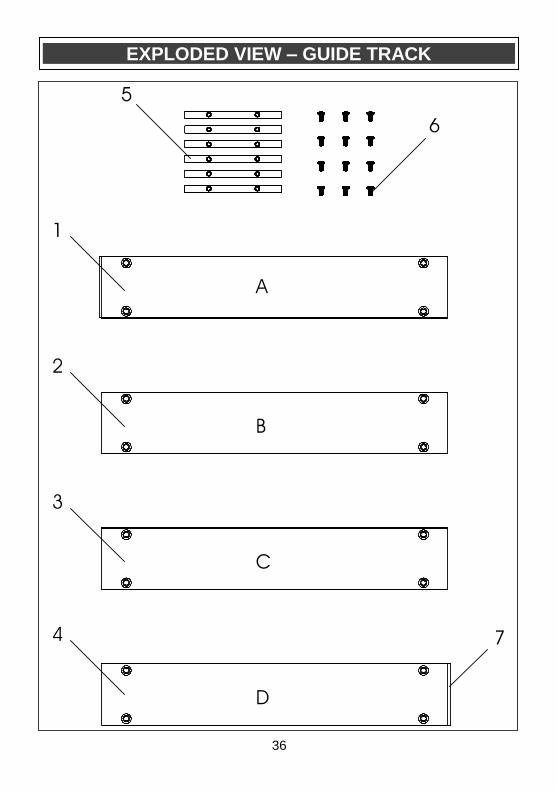
EXPLODED VIEW – GUIDE TRACK

37
WARNING: When servicing, use only Mastercraft® replacement parts. The use of
any other parts may create a safety hazard or cause damage to the easy saw. Any attempt to repair or replace electrical parts on this easy saw may create a safety hazard unless repairs are performed by a qualified technician. For more information, call the Toll-free Helpline, at 1-800-689-9928. Always order by PART NUMBER, not by key number.
Key # Part # Part Name Quantity
1 4030010096 Tapping screw 3.9X12 5
2 3160010044 Back cover 1
3 4020010034 Screw M5x52 1
4 4020010035 Screw M5x60 2
5 4040030003 Spring washer 5 mm 3
6 4040010012 Flat washers 5 mm 3
7 4030010106 Tapping screw 4X19 10
8 3120070075 Handle 1
9 1210190002 Overload protector 1
10 1062020030 Switch 1
11 1130090006 PCB 1
12 1210140003 120V transformer 1
13 3120010051 Laser button 1
14 3011120005 Housing 1
15 4100050011 Circlip 8 mm 1
16 2030100040 Plunge pivot bracket 1
17 2020060015 Bevel scale 1
18 2030020017 Washers 6 mm 1
19 3120100036 Locking lever 2
20 4100050012 Clamp spring 10 mm 2
21 2040150020 Serrated nut M6 2
22 4090040012 Rivet Φ6x16 2
23 4040010033 Flat washer 8 mm x .8 mm 1
24 2040290045 Plunge pivot shaft 1
25 4050040005 Cup head square neck bolt M6x25 1
26 2050050029 Plunge torsional spring 1
27 4030010126 Tapping screw 4x65 2
28 3150050048 Air deflector 1
29 1020120007 Stator 1
30 3160090061 Pivot spring cover 1
31 2040160123 Pin 5 mm 1
PARTS LIST
!

38
Key # Part # Part Name Quantity
32 3140040012 629 bearing cover 1
33 3150060030 Plastic brush support 2
34 2030070010 Copper brush sleeve 2
35 1230010076 Carbon brush 2
36 3150140019 Carbon brush cover 2
37 4030010099 Tapping screw 4X14 2
38 2030050002 Cable clamp 1
39 3140010006 Cable guard 1
40 1190030031 Cable 1
41 4010010084 629 2RS bearing 1
42 1010120007 Rotor 1
43 3140070016 Spindle lock cover 1
44 2030030175 Spindle lock 1
45 2050060011 Spindle lock spring 1
46 4010010055 6001 2RS bearing 1
47 4020010006 Screw M4x12 (galvanized) 3
48 4040030001 Spring washer 4 mm 3
49 4020120005 Clamping screw M3x10 2
50 2020020020 Gear box 1
51 3160060008 Laser holder 1
52 1220030006 Laser 1
53 3140090001 Rubber bushing 1
54 4020080007 Hex head screw M6x16 1
55 4010020003 HK0810 2
56 2030020203 Flat thrust washer 8 mm 2
57 4120010002 Flat key 5x10 2
58 2040040053 Transmission shaft 1
59 2040080015 Transmission gear 1
60 2020150054 Gear box cover 1
61 2020080030 Fixed guard 1
62 4020120009 Screw M4x12 1
63 2050050030 Moveable guard torsional spring 1
64 2020080031 Moveable guard 1
65 4100020009 Circlip for shaft 36 mm 1
66 2040210003 Inner flange 1
67 6070050003 Blade 1
68 2040210004 Outer flange 1
69 4040030013 Lock washer 6 mm 1
70 4020080006 Hex head screw M6x20 1
71 3120100037 Metal cutting guard locking lever 1
72 2030130030 Metal cutting guard 1
73 3150130100 Metal cutting guard lock 1
PARTS LIST

39
Key # Part # Part Name Quantity
74 4020010003 Screw M4x12 (black) 1
75 2030020163 Flat washer 4x11 (black) 1
76 2050060141 Moveable guard tortional spring 1
77 3120100038 Tortional spring stop 1
78 4020010103 Screw M3x8 (black) 2
79 3180040097 Vacuum dust port 1
80 3140070017 Vacuum dust port baffle cover 1
81 3180040098 Vacuum dust port baffle 1
82 4020010019 Screw M5x14 (galvanized) 2
83 4020020005 Countersunk screw M5x12 5
84 4010010081 6201 2RS bearing 1
85 2040080016 Big gear 1
86 2040040054 Output shaft 1
87 4100020011 Circlip for shaft 15 mm 1
88 4010020014 HK101410 1
89 4020010001 Screw M4x8 (galvanized) 1
90 2030160100 Lead clamp 1
91 3160090067 Air baffle 1
92 4050040006 Cup head square neck bolt M6x40 1
93 3150160131 Depth gauge housing (right) 1
94 2030030176 Depth gauge 1
95 3120020098 Depth adjusting button 1
96 2050040039 Depth button spring 1
97 3120120098 Depth slider 1
98 2040160124 Depth button pin 1
99 3150160132 Depth gauge housing (left) 1
100 3150130101 Track rider 1
101 2040160025 Cross pin 2
102 2040160125 Track rider locking pin 2
103 2050060142 Track rider locking lever spring 2
104 3120100039 Track rider locking lever 2
105 2050060143 Edge guide locking knob spring 1
106 2050060010 Edge guide locking knob 1
107 2020120033 Sole plate 1
108 3150130102 Zero clearance insert 3
109 6220040011 Rip guide 1
110 2030100041 Depth adjusting support 1
111 6140020001 Hex key 5 mm 1
PARTS LIST

40
Key # Part # Part Name Quantity
1 2020210006 Track section "A" 1
2 2020210007 Track section "B" 1
3 2020210008 Track section "C" 1
4 2020210009 Track section "D" 1
5 2040160132 Joining Rod 6
6 4020020001 Screw 12
7 3160090066 Track end cap 2
PARTS LIST – GUIDE TRACK

41
3-Year Limited Warranty This Mastercraft product is guaranteed for a period of 3 years from the date of original retail purchase against defects in workmanship and materials, except for the following components:
a) Component A: Batteries, chargers and carrying cases, which are guaranteed for a period of 2 years from the date of original retail purchase against defects in workmanship and materials;
b) Component B: Accessories which are guaranteed for a period of 1 year from the date of original retail purchase against defects in workmanship and materials.
Subject to the conditions and limitations described below, this product, if returned to us with proof of purchase within the stated warranty period and is covered under this warranty, will be repaired or replaced (with the same model, or one of equal value or specification),at our option. We will bear the cost of any repair or replacement and any costs of labour relating thereto. These warranties are subject to the following conditions and limitations:
a) A bill of sale verifying the purchase and the purchase date must be provided;
b) This warranty will not apply to any product or part thereof that is worn, broken or that has become inoperative due to abuse, misuse, accidental damage, neglect or lack of proper installation, operation or maintenance (as outlined in the applicable owner’s manual or operating instructions) or that is being used for industrial, professional, commercial or rental purposes;
c) This warranty will not apply to normal wear and tear or to expendable parts or accessories that may be supplied with the product that are expected to become inoperative or usable after a reasonable period of use;
d) This warranty will not apply to routine maintenance and consumable items such as, including but not limited to, fuel, lubricants, vacuum bags, blades, belts, sandpaper, bits, fluids, tune-ups or adjustments;
e) This warranty will not apply where damage is caused by repairs made or attempted by others (i.e.: persons not authorized by the manufacturer);
f) This warranty will not apply to any product that was sold to the original purchaser as a reconditioned or refurbished product (unless specified otherwise in writing);
Page 1 of 2

42
3-Year Limited Warranty – cont’d These warranties are subject to the following conditions and limitations:
g) This warranty will not apply to any product or part thereof if any part from another manufacturer is installed therein or any repairs or alterations have been made or attempted by unauthorized persons;
h) This warranty will not apply to normal deterioration of the exterior finish, such as, including but not limited to, scratches, dents, paint chips, or to any corrosion or discoloring by heat, abrasive and chemical cleaners; and
i) This warranty will not apply to component parts sold by and identified as the product or company, which shall be covered under the product manufacturer’s warranty, if any.
Additional Limitations
This warranty applies only to the original purchaser, and cannot be transferred. Neither the retailer not the manufacturer shall be liable for any other expense, loss or damage, including, without limitation, but not limited to any indirect, incidental, consequential or exemplary damages arising in connection with the sale, use or inability to use this product. Notice to Consumer
This warranty gives you specific legal rights, and you may have other rights, which may vary from province to province. The provisions contained in this warranty are not intended to limit, modify, take away from, disclaim or exclude any statutory warranties set forth in any applicable provincial or federal legislation. Mastercraft is a superior line of products selected for their workmanship and materials. These products are designed to meet rigorous quality and performance standards, and are approved by our Quality Assurance laboratory.
TOLL-FREE HELPLINE: 1-800-689-9928
Page 2 of 2
Rev 1.8 10/11/2010