easytouch operation manual
TRANSCRIPT

EasyTouch Operation Manual
2.5” Color TFT Touch Screen Controller for FX1 & FX2 Control Boards
Micro-Air, Inc. www.microair.net 124 Route 526 Ph: (609) 259-2636 Allentown, NJ 08501 Fax: (609) 259-6601

Micro-Air, Inc. Page 2 EasyTouch Operations Manual Rev 3.0 4/3/17
TABLE OF CONTENTS
1. INTRODUCTION .................................................................................................................. 4
2. READ THIS MANUAL BEFORE PROCEEDING ................................................................ 4
3. FEATURES .......................................................................................................................... 4 3.1 Standard ..................................................................................................................................................... 4 3.2 Optional ...................................................................................................................................................... 4 3.3 Control Boards and Options Supported by EasyTouch ............................................................................. 5
4. OVERVIEW .......................................................................................................................... 6 4.1 EasyTouch Home & Main Screen Displays ............................................................................................... 6 4.2 EasyTouch Power-Up & Default Sleep Mode Screen Display ................................................................... 6
5. INSTALLING THE DISPLAY PANEL .................................................................................. 6 5.1 Choosing the Location ................................................................................................................................ 6 5.2 Installing the Battery (for older EasyTouch models only) ........................................................................... 6 5.3 Mounting the Display .................................................................................................................................. 7
6. INSTALLING THE OPTIONAL SENSORS .......................................................................... 8 6.1 Remote (Alternate) Air Temperature Sensor ............................................................................................. 8 6.2 Outside Air Temperature Sensor................................................................................................................ 8 6.3 Service Sensor (for DX systems only) ....................................................................................................... 8 6.4 Water Inlet Temperature Sensor (for CW systems only) ........................................................................... 8 6.5 Combination Temp/Humidity Sensors (for CW & FAMU FX2 systems only) ............................................. 9
7. NORMAL HEATING OR COOLING CYCLE ....................................................................... 9 7.1 Reversing Valve Operation (for DX systems only) ..................................................................................... 9 7.2 Water Valve Operation (for CW systems only) .......................................................................................... 9
8. STANDARD OPERATION ................................................................................................. 10 8.1 Operator Controls and Display ................................................................................................................. 10 8.2 Modes of Operation .................................................................................................................................. 12 8.3 Fan Speed Modes .................................................................................................................................... 13
9. FRESH AIR MAKEUP (FAMU) OPERATION ................................................................... 14 9.1 FAMU Operator Controls and Display ...................................................................................................... 15 9.2 FAMU Sequence of Operation ................................................................................................................. 16 9.3 FAMU Settings & Recommendations ....................................................................................................... 18
10. FAULTS ............................................................................................................................. 18 10.1 Air Sensor Fault (DX & CW, immediate lockout)...................................................................................... 19 10.2 FAMU Sensor Faults (FAMU only, immediate lockout) ........................................................................... 19 10.3 High Pressure Fault (DX & FAMU DX only, contributes to lockout count) ............................................... 19 10.4 Low Pressure Fault (DX & FAMU DX only, contributes to lockout count) ............................................... 19 10.5 Low AC Fault (DX & FAMU DX only, no lockout)..................................................................................... 20 10.6 Pump Sentry Fault (DX & FAMU DX only, contributes to lockout count) ................................................. 20 10.7 Overcurrent Fault (DX & FAMU DX only, contributes to lockout count)................................................... 20 10.8 Lost AC Fault (DX & FAMU DX Only, no lockout).................................................................................... 20 10.9 EasyStart Fault (DX & FAMU DX only, contributes to lockout count) ...................................................... 21
11. MENU AND SETTINGS OVERVIEW ................................................................................. 21 11.1 Menu Screen ............................................................................................................................................ 21 11.2 Settings Screen ........................................................................................................................................ 22
12. CONTROL PARAMETERS MENU .................................................................................... 22 12.1 General Settings ....................................................................................................................................... 23 12.2 Fan Speed Settings .................................................................................................................................. 30 12.3 DX Operational Settings ........................................................................................................................... 32 12.4 CW Operational Settings .......................................................................................................................... 36 12.5 FAMU DX Operational Settings................................................................................................................ 37 12.6 FAMU CW Operational Settings............................................................................................................... 38

Micro-Air, Inc. Page 3 EasyTouch Operations Manual Rev 3.0 4/3/17
12.7 Memorize Settings .................................................................................................................................... 39 12.8 Recall Memorized Settings ....................................................................................................................... 39 12.9 Recall Default Settings ............................................................................................................................. 40
13. PROGRAM SCHEDULER MENU ...................................................................................... 40 13.1 Mode Control and Operational Behaviors ................................................................................................ 40 13.2 Programming a Day or Group of Days ..................................................................................................... 41
14. DATE/TIME MENU ............................................................................................................ 41 14.1 Enabling the Date/Time Display ............................................................................................................... 42 14.2 Changing the Date/Time Format .............................................................................................................. 42 14.3 Setting the Date & Time ........................................................................................................................... 42
15. SYSTEM MENU ................................................................................................................. 43 15.1 Firmware Version ..................................................................................................................................... 43 15.2 Display Setup ........................................................................................................................................... 43 15.3 Sleep Mode Settings ................................................................................................................................ 44 15.4 Display Lock ............................................................................................................................................. 45 15.5 Cleaning Mode ......................................................................................................................................... 47 15.6 Wi-Fi Settings (optional EasyTouch feature) ............................................................................................ 47
16. TROUBLESHOOT & COMMISSION MENU ...................................................................... 48 16.1 System Status .......................................................................................................................................... 49 16.2 Help & Information .................................................................................................................................... 49 16.3 Commission Procedure ............................................................................................................................ 49
17. FAULT HISTORY & RUN HOURS MENU ......................................................................... 50 17.1 Fault History ............................................................................................................................................. 50 17.2 Compressor Run Hours ............................................................................................................................ 51 17.3 Fan Run Hours ......................................................................................................................................... 51
18. SPECIFICATIONS ............................................................................................................. 52
19. WARRANTY AGREEMENT .............................................................................................. 53

Micro-Air, Inc. Page 4 EasyTouch Operations Manual Rev 3.0 4/3/17
1. INTRODUCTION The EasyTouch Control is a microcontroller-based unit designed for use with direct expansion, reverse-cycle air conditioning systems or with chilled-water air handlers.
2. READ THIS MANUAL BEFORE PROCEEDING Read this manual completely before you proceed with the installation and operation of the EasyTouch. If you have questions or require assistance with your EasyTouch control, contact Micro-Air at +1 (609) 259-2636. The EasyTouch is covered under the Micro-Air Warranty Policy, and incorrect installation, neglect and system abuse are not covered under warranty policy. See section 19 for more details.
3. FEATURES 3.1 Standard
Works automatically via auto-detection with FX1 or FX2 control circuit boards.
User-friendly and intuitive 2.5” touch screen display requires no manual for basic operation.
Five-volt logic and microcontroller located in the display.
Automatic and three programmable manual fan speeds.
Numerous programmable parameters for custom installations.
Moisture Mode for controlling relative humidity.
De-Icing cycle to prevent evaporator coil icing.
Programmable compressor staging delays.
Universal 115-230V, 50/60Hz AC power supply.
Nonvolatile memory retains settings without batteries.
Programmable display-brightness control.
Programmable failsafe modes.
Integrated CAN-bus network capability
Low-Voltage Monitor.
AC Current Monitor
Fits Vimar® Eikon and Eikon EVO bezels.
3.2 Optional Outside air temperature sensor.
Alternate air temperature sensor.
Pump Sentry (Service) water sensor.
Combination Temp/%RH sensor for Cabin Relative Humidity Control in CW
Electric heating control capabilities in reverse-cycle DX and in CW.
Air Filter Cleaning or Replacement Timer.
Fresh Air Makeup (FAMU) DX and CW Control
Expanded 4x DC Blower Output (daughterboard) support
EasyStart Soft Starter (daughterboard) support
Wi-Fi support for EasyTouch smart phone application

Micro-Air, Inc. Page 5 EasyTouch Operations Manual Rev 3.0 4/3/17
3.3 Control Boards and Options Supported by EasyTouch The EasyTouch has evolved and supports all of the features available in the original FX1 and in the newest FX2 Control Boards. Please refer to the following chart below for the minimum required firmware versions for the EasyTouch to support the control features required.
Table 1 – Control Boards & Options Supported by EasyTouch
1 One DC Blower output is integrated into base control board, and can support up to 2 DC blowers in
parallel 2 Four separate DC blower outputs are available on the daughterboard with individual fan speed programming. The one DC blower output integrated into the base control board can still be used and its speed settings follow that of Fan A.
This manual provides all necessary information for proper installation and operation of the EasyTouch Display. Poor installation and misunderstood operating parameters will result in unsatisfactory performance and possible failure.
Stan
dar
d
Cab
in %
RH
FAM
U
AC
Cu
rren
t
Lim
it
CA
N B
us
Easy
Star
t
DC
Blo
wer
Wi-
Fi
FX1 ASY-370-X09 FX1 Control Board, standard All Any
ASY-360-XG1 FX2 Control Board, standard G1 and older Any
ASY-360-XG11FX2 Control Board, with 731 Temp/Humidity
Sensor Daughterboard Option (depopulated)G1 N05 or newer
ASY-360-XG2FX2 Control Board, with 361 CAN Bus
Daughterboard Optionn/a n/a
ASY-360-XG4FX2 Control Board, with 361 Expanded
DC Blower Daughterboard Optionn/a n/a
ASY-360-XG5FX2 Control Board, with 367 EasyStart™
Daughterboard Optionn/a n/a
ASY-360-XG8FX2 Control Board, with 731 FAMU
Daughterboard Optionn/a n/a
ASY-360-XL1/3FX2 Control Board, standard w/ Integrated
CAN Bus SupportJ and newer 11
N07 or newer
N10 for Wi-Fi
ASY-360-XL4FX2 Control Board, with 361 Expanded
DC Blower Daughterboard OptionJ and newer 4
2 N07 or newer
N10 for Wi-Fi
ASY-360-XL4/5FX2 Control Board, with 521 EasyStart™
Daughterboard OptionJ and newer 11
N07 or newer
N10 for Wi-Fi
FX2
1st Gen
FX2
2nd Gen
Not Supported
Not Supported
Not Supported
Not Supported
Required
EasyTouch
Firmware
Version
Control
Family
Control Board
Micro-Air P/N Control Board Description
Control
Board
Hardware
Versions
Supported Control Features

Micro-Air, Inc. Page 6 EasyTouch Operations Manual Rev 3.0 4/3/17
4. OVERVIEW 4.1 EasyTouch Home & Main Screen Displays
The EasyTouch Home screen shown in Figure 1 consists of large, easy to read graphics, with large buttons for basic control functions. The Main screen shown in Figure 2 consists of smaller graphics showing all of the controls readouts and statuses, and had more buttons for all of the control functions.
Figure 1 – Home Screen Display Figure 2 – Main Screen Display
4.2 EasyTouch Power-Up & Default Sleep Mode Screen Display During power up and whenever the display enters Sleep Mode, the display shown in Figure 3 is shown. While in Sleep mode, the graphic will move around the screen. See section 15.3 for more information on the various Sleep Mode settings.
Figure 3 – Power-Up & Default Sleep Screen Display
5. INSTALLING THE DISPLAY PANEL 5.1 Choosing the Location
Before mounting the control panel, consider the location. The display panel’s built-in air sensor provides excellent room-air temperature sensing when properly located and installed. The physical location of the air sensor is shown in Figure 4 and marked with “S”. Be sure to mount the display panel on an inside wall, slightly higher than mid-height of the cabin, in a location with freely circulating air where it can best sense average temperature. The display’s distance from the air conditioner must be within the 15’ (4.5m) length of the display cable. Longer, custom cable lengths are also available.
5.2 Installing the Battery (for older EasyTouch models only) Starting in second half of 2015, all EasyTouch display will be supplied with a rechargeable battery that requires no installation or maintenance. Previous models will be supplied with a loose type CR2032 battery that must be installed before mounting the display. The purpose of this battery is to maintain the time clock and date calendar only whenever AC power is removed from the EasyTouch. The battery has nothing to do with numerous programmable settings and features of EasyTouch, all of which are stored in non-volatile memory that does not require a battery.

Micro-Air, Inc. Page 7 EasyTouch Operations Manual Rev 3.0 4/3/17
Figure 4 – EasyTouch Display Front Panel
IMPORTANT: Do not mount the display in direct sunlight, near any heat-producing appliances or in a bulkhead where temperatures radiating from behind the panel may affect performance. Do not mount the display in the supply-air stream. Do not mount the display above or below a supply-air or return-air grille. Do not mount the display behind a door, in a corner, under a stairwell or any place where there is no freely circulating air. If you cannot mount the display in a suitable location for accurately sensing room temperature, install the optional remote air sensor as explained in section 6.1.
5.3 Mounting the Display
1. Choose a wall location that has adequate depth (at least 1”/25.4mm) behind the wall itself. See Figure 5 for the depth dimensions of the display.
Figure 5 – EasyTouch Display Top View Mounting Dimensions
2. Make the cut-out for the display panel as shown in Figure 6. Cut-out size is 2.900” (74mm) wide by 2.165” (55mm) tall.
S

Micro-Air, Inc. Page 8 EasyTouch Operations Manual Rev 3.0 4/3/17
Figure 6 – EasyTouch Display Mounting Dimensions
3. Plug one end of the display cable (8-pin connector) into the display jack on the circuit board in the electric box and the other end into the back of the display panel.
4. Secure the display panel to the bulkhead using the four screws provided. Do not use a screw gun and do not over tighten screws when mounting, because either method may damage the display.
5. When the display is securely mounted, mount the bezel over the display frame until it snaps into place.
6. INSTALLING THE OPTIONAL SENSORS 6.1 Remote (Alternate) Air Temperature Sensor
Install the optional remote air sensor if the display cannot be mounted in a proper location for accurately sensing room temperature. Installing the remote air sensor overrides the display’s built-in sensor. The standard cable length for the remote air sensor is 7 feet (2.1m).
1. Mount the remote air sensor in a reliable return-air stream, preferably just behind the opening of the return-air grille. DO NOT attach the sensor to the edge of the unit’s drain pan since the condensate water and cold air spilling off of the heat exchanger coil will cause an inaccurate temperature reading.
2. Plug its cable (6-pin connector) into the “ALT. AIR” or “ALT. AIR / RH” jack on the circuit board.
6.2 Outside Air Temperature Sensor Install the optional outside air temperature sensor to monitor the temperature outside the cabin. Outside air sensor cables are available in various lengths.
1. Mount the sensor outside but not in direct sunlight. 2. Plug its cable into the “OAT” jack on the circuit board.
6.3 Service Sensor (for DX systems only) Install the optional condenser coil temperature sensor into the “OAT/H20” jack on the FX1 circuit board or into the “SERVICE” header on the FX2 circuit board.
1. Mount the sensor in the middle of the condenser coil, strapping it securely to the piping. 2. Enabled the use of this sensor by going to DX Operational Settings, and then the Pump Sentry
feature as explained in section 12.3.5.
6.4 Water Inlet Temperature Sensor (for CW systems only) When using the EasyTouch with a chilled-water air handler, plug the water-inlet sensor cable into the “OAT/H2O” jack on FX1 or into the “OUTSIDE / RH” jack on FX2. Attach the sensor securely to the

Micro-Air, Inc. Page 9 EasyTouch Operations Manual Rev 3.0 4/3/17
chilled-water inlet pipe on the air handler. Ensure that the sensor makes good contact with the copper pipe and make sure it is covered with adequate insulation. DO NOT attach the sensor to rubber hose.
6.5 Combination Temp/Humidity Sensors (for CW & FAMU FX2 systems only) As described in the table in section 3.3, the EasyTouch supports an optional temperature and relative humidity sensor for cabin %RH control and for Fresh Air Makeup (FAMU) operation on FX2 control boards only. For FX2 control boards with hardware revision is available only with the FX2 control board. For FX2 control board rev J and newer, plug the combo temperature/humidity sensor into the “ALT. AIR / RH” jack for cabin %RH control, and plug in an additional combo temperature/humidity sensor into the “OUTSIDE / RH” jack for FAMU control operation. For FX2 control board revisions G1 and older, the optional Temp/Humidity Sensor daughterboard is required to support cabin %RH control only; plug the combo temperature/humidity sensor into the “INTAKE” jack on the daughterboard and insure that the Inside Temp Sensor Selection programming parameter is set to “AUTO” (see section 12.1.16). The cabin temperature and humidity control feature is enabled automatically once a combo temperature/humidity sensor is detected in either the “ALT. AIR / RH” or “INTAKE” jacks on the FX2 board revisions described above. See section 12.1.11 for more information on using the humidity control feature. The FAMU control feature must be deliberately enabled in order to take effect. See section 9 for more information on setting up FAMU control operation.
7. NORMAL HEATING OR COOLING CYCLE In Automatic Mode, heating and cooling are supplied as required. If cooling is required, the system will start a cooling cycle when the cabin temperature exceeds the set point by 2°F (1.0°C) and will continue to cool until the temperature equals the set point. (See the parameter setting Set Point Temperature Differential as described in section 12.1.3 for more information on how to change this variation to 1°F [0.5°C].) The cabin temperature must drop below the set point by at least 4°F (2.0°C) in order for the system to switch from cooling to heating. Similarly, if heating is required, the system will start a heating cycle when the cabin temperature is below the set point by 2°F (1.0°C) and will continue to heat until the temperature equals the set point. The cabin temperature must exceed the set point by at least 4°F (2.0°C) in order for the system to switch from heating to cooling. If you select Cool Mode, only cooling is supplied. If you select Heat Mode, only heating is supplied. The cabin temperature in either mode is maintained within 2°F (1.0°C) of set point by default. When the heating or cooling set point is satisfied, the compressor cycles off and the fan returns to low speed. The fan speed remains constant if Manual Fan Speed is selected. For more information on the fan speed control and its operation, see section 8.3.
7.1 Reversing Valve Operation (for DX systems only) The position of the reversing valve determines if the system is in Cool Mode or Heat Mode. The EasyTouch and FX1/FX2 systems are designed to energize the reversing valve output when in Heat Mode. In addition, the reversing valve will toggle into the opposite position for 2 seconds to equalize the system pressure and reduce the compressor’s starting surge whenever a cooling or heating cycle is called for and the system has been off for less than 75 seconds. Unnecessary valve toggling is limited to reduce reversing valve noise.
7.2 Water Valve Operation (for CW systems only) When cooling or heating is required, the water valve will not open unless the water temperature is adequate. The fan remains in low speed until the adequate water temperature is available and the system status on the Main display screen will show “Cool Pending” or “Heat Pending”. If the optional Electric Heater is enabled, heating will be provided if the water temperature is not adequate. See the Water Temperature Differential parameter setting described in section 12.4.2 for a definition of adequate cooling or heating water temperature and how to adjust its factory default setting to something other than 10°F (6°C).

Micro-Air, Inc. Page 10 EasyTouch Operations Manual Rev 3.0 4/3/17
8. STANDARD OPERATION 8.1 Operator Controls and Display
8.1.1 Home Screen Indicators & Buttons
Figure 7 – EasyTouch Home Screen Icons & Functions
1. Force Sleep Mode Button - Press and release to force Sleep Mode to initiate immediately, if enabled. See section 15.3 for more information on Sleep Mode.
2. Temperature Display Selection – Indicates the current temperature display value: SET, INSIDE, OUTSIDE, SERVICE/WATER, or %RH. If the associated temperature sensor is not installed or is faulty, “- - -” will be displayed.
3. Status Indicator – This display area indicates the abbreviated operational status of the control, including standby and active states, fault states, fault recovery, and fault lockout. More information on the operational status is available on the Main Screen.
4. Temperature Display Indicator – This value indicates the current temperature reading that corresponds to the Temperature Display Selection explained above. Press and release over the top of the numeric value to select the various temperature displays: Set point(s), Inside, Outside, Service/Water temperatures, or Relative Humidity (if equipped). By default, the temperature display will always revert back to showing the Inside Temperature after 3 seconds. If you wish to change the default Temperature Display to one of the other available choices, immediately after selecting the desired temperature, press and hold again for 5 seconds (until the button highlight disappears) and the currently displayed temperature will be retained and reverted back to.
5. More Button - Press and release to change display to Main Screen.
6. Up Button - Press and release to display the set point. Press and release or press and hold the UP button to increase the set point.
7. Down Button - Press and release to display the set point. Press and release or press and hold to decrease the set point.
8. Power On/Off Button - Press and release to toggle between the ON (green) and OFF (red) operation.
9. Wi-Fi Network Status Indicator Icon – If the EasyTouch display has the optional Wi-Fi support feature installed, a Wi-Fi icon will appear and indicate the status of the Wi-Fi connection. Green=connected, Yellow=connecting in progress, and Red=connection failed/disconnected.
6
7
8
1
2
3
4
5
9

Micro-Air, Inc. Page 11 EasyTouch Operations Manual Rev 3.0 4/3/17
8.1.2 Main Screen Indicators & Buttons
Figure 8 – EasyTouch Main Screen Icons & Functions
1. Mode Button - The Mode button indicates the currently active mode of operation. Press and release to step through the four available operating modes: COOL, HEAT, AUTO, and MOISTURE. See section 8.2 for more information on all the modes of operation.
2. Fan Speed Mode Indicator – This label indicates the current fan speed mode, AUTO or MANUAL. See section 8.3 for more information on the fan speed mode.
3. Fan Speed Indicator – This indicator is a bar graph that shows the speed at which the fan is currently operating. There are 3 fan speeds with EasyTouch: 1 bar lit indicates low speed, 4 bars lit indicate medium speed, and 7 bars lit indicate high speed.
4. Fan Button – The Fan button is used to control the fan speed. The Fan button will rotate when the fan is on, and will be stationary when the fan is off. See section 8.3 for more information on the controlling the fan speed.
5. Menu Button – The Menu button allows access to the EasyTouch Main Menu and all sub-menus beyond. See section 11 for more information on the menus.
6. Up Button - Press and release to display the set point. Press and release or press and hold the UP button to increase the set point.
7. Temperature Display Selection – Indicates the current temperature display value: SET, INSIDE, OUTSIDE, SERVICE/WATER, or %RH. If the associated temperature sensor is not installed or is faulty, “- - -” will be displayed.
8. Temperature Display Indicator – This value indicates the current temperature reading that corresponds to the Temperature Display Selection explained above. Press and release over the top of the numeric value to select the various temperature displays: Set point(s), Inside, Outside, Service/Water temperatures, or Relative Humidity (if equipped). By default, the temperature display will always revert back to showing the Inside Temperature after 3 seconds. If you wish to change the default Temperature Display to one of the other available choices, immediately after selecting the desired temperature, press and hold again for 5 seconds (until the button highlight disappears) and the currently displayed temperature will be retained and reverted back to.
9. Down Button - Press and release to display the set point. Press and release or press and hold to decrease the set point.
12 11
14 15 13
6
7
8
9
10
1
2
3
4
5
16

Micro-Air, Inc. Page 12 EasyTouch Operations Manual Rev 3.0 4/3/17
10. Power On/Off Button - Press and release to toggle between the ON (green) and OFF (red) operation.
11. Date & Time Display – The date and time are displayed here, if enabled. See section 14 for information on how to set the date & time, change formats, and enable or disable the display.
12. Home Button – Hidden behind the Micro-Air logo is a button that when pressed returns the display to the Home Screen.
13. Operational Status & Fault Help Button – This display area indicates the current operational status of the control, including standby and active states, fault states, fault recovery, and fault lockout. If a fault is active, touching this status area will display the Fault Help screen for the active fault. See section 9.3.2 for more information on fault displays.
14. Program Scheduler Status and Resume Button – This display area indicates the current operational status of the Program Scheduler. If the Program Scheduler is currently in an Override state, touching this status area will cause the Program Scheduler to resume the active program for the current time & date period. See section 13 for more information on the Program Scheduler.
15. Filter Maintenance Status – If enabled, this display area indicates when it is time to clean or replace the air filter. See section 12.1.6 for more information on the Air Filter Reminder.
16. Wi-Fi Network Status Indicator Icon – If the EasyTouch display has the optional Wi-Fi support feature installed, a Wi-Fi icon will appear and indicate the status of the Wi-Fi connection. Green=connected, Yellow=connecting in progress, and Red=connection failed/disconnected.
8.2 Modes of Operation
8.2.1 OFF Mode When the control is in OFF Mode, all control outputs are turned off. Upon entering OFF mode, if the electric heater was active within the previous 4 minutes, the fan will remain on at low speed for up to 4 additional minutes to cool down the electric heater.
8.2.2 ON Mode When the control is in ON Mode, power is supplied to the appropriate outputs and the display indicates the current state of operation.
8.2.3 AUTO Mode When AUTO Mode is selected as indicated by the Mode button icon, the system provides both heating and cooling as required. The Inside temperature in is maintained within 2°F (or 1.0°C) of set point by default. See section 12.1.3 for more information on the Set Point Temperature Differential parameter setting and how it can be adjusted. If the system was most recently cooling, the cabin temperature must drop below the set point by at least 4°F (or 2.0°C) by default in order for the system to switch from cooling to heating. Similarly, if the system was most recently heating, the cabin temperature must exceed the set point by at least 4°F (or 2.0°C) by default in order for the system to switch from heating to cooling. This behavior prevents small temperature overshoots from causing the system to switch between heating and cooling when it is not necessary.
8.2.4 COOL Mode When COOL Mode is selected as indicated by the Mode Button icon, only the cooling system operates as required. If the ambient temperature drops below the set point, the system will not automatically switch to the HEAT Mode.
8.2.5 HEAT Mode When HEAT Mode is selected as indicated by the Mode Button icon, only the heating system operates as required. If the ambient temperature rises above the set point, the system will not automatically switch to the COOL Mode.
8.2.6 MOISTURE Mode MOISTURE Mode, sometimes called “Humidity” or “Dehumidification” mode, is used to help control humidity while you are away from the boat or away from a particular cabin. Once

Micro-Air, Inc. Page 13 EasyTouch Operations Manual Rev 3.0 4/3/17
MOISTURE Mode is enabled as indicated by the Mode Button Icon, the fan circulates the air for 30 minutes. During this time, the air temperature is sampled and entered into memory. After 30 minutes, a cooling cycle starts and continues until the temperature is lowered 2°F (or 1.0°C) or until the cooling cycle runs a maximum of one hour. Four hours after the temperature is satisfied or the cooling cycle times out, this cycle repeats. Moisture Mode will also prevent your boat or a particular cabin from dropping below a minimum temperature as a means to prevent the contents from freezing. When the temperature drops low, eliminating moisture may become less of a concern and maintaining some minimum temperature may become more important. After the 30-minute fan circulation, if the temperature is at or above the Humidity Mode Minimum Temp (50°F/10°C, by default), a cooling cycle is started and runs as described above. However, if the temperature is below the Humidity Mode Minimum Temp, a heating cycle will be started instead. The heating cycle will continue until the temperature reaches the Humidity Mode Minimum Temp or until the heating cycle runs a maximum of one hour. Four hours after the temperature is satisfied or the cooling/heating cycle times out, the entire cycle repeats, each time determining whether cooling or heating is required. See section 12.1.11 for more information on how to adjust the Humidity Mode Minimum Temp parameter setting to a temperature that may better suit your particular requirements. IMPORTANT (for DX systems only): If your air conditioning unit is Cool-Only (i.e. it does not have a reversing valve) and an Electric Heater is not installed or enabled, then COOL Mode MUST be selected. DO NOT use AUTO or HEAT modes for a Cool-Only unit. If either AUTO or HEAT modes are selected with a Cool-only unit and the thermostat calls for heating, the compressor will run and still provide cooling.
8.3 Fan Speed Modes
8.3.1 Automatic Fan Speed Mode EasyTouch has three automatic fan speeds available: High, Medium and Low. While in the On Mode, Automatic Fan Speed Mode allows the EasyTouch to determine the required fan speed based upon the set point temperature differential. This permits a balance between the most efficient temperature control and slower, quieter fan speeds. To select Automatic Fan Speed Mode, on the Main Screen press and release the Fan Button as many times as necessary until the word “AUTO” is displayed above the fan speed bar graph.
8.3.2 Manual Fan Speed Mode There are three manual fan speeds available: High, Medium and Low. While in the On Mode, Manual Fan Speed Mode allows you to select and maintain a desired fan speed. To select Manual Fan Speed Mode, on the Main Screen press and release the Fan Button until the desired speed is indicated on the Fan Speed bar graph and the word “MANUAL” is displayed above the fan speed bar graph. The selected fan speed will increase and decrease as the Fan Button is repeatedly pressed until the Fan Speed Mode is returned back to Automatic.
8.3.3 Fan-Only Mode While in the Off Mode, use the Fan-Only Mode to operate the fan for air circulation when no cooling or heating is desired. On the Main Screen, press and release the Fan Button to start at low fan speed. Press and release again to select Medium fan speed. Press and release a third time to select High fan speed. Press and release a fourth time to turn off the fan. Putting the control into ON Mode will cancel the Fan-Only Mode and revert the fan speed back to the Automatic Mode or whatever the last selected manual fan setting was. NOTE: Please refer to section 12.1.11 for more information on the Fan Operational Modes, Continuous or Cycled.

Micro-Air, Inc. Page 14 EasyTouch Operations Manual Rev 3.0 4/3/17
9. FRESH AIR MAKEUP (FAMU) OPERATION A Fresh Air Makeup (FAMU) system is meant to draw in and condition outside air and drive it into the interior cabin areas. The air drawn in from the outside is considered the “intake”, and the air discharged into the cabin is considered the “exhaust”. The FAMU unit must condition the outside air in a single pass through the system. FAMU systems therefore must incorporate both cooling and electric heating. EasyTouch supports FAMU operation for both DX and CW systems using the FX2 Control Board, rev J and newer. Please refer to the FX2 Control Board User Manual for further details on how to wire the FX2 control board to a FAMU system (available on the Micro-Air website at this link). A FAMU system takes warm and moist intake air at temperature T1, dew point DP1, and relative humidity %RH1, and will first cool and dry the air to a lower dew point DP2 at a temperature lower than the desired exhaust set point. Then, the FAMU system will reheat the air, increasing only its dry bulb temperature, further reducing its relative humidity, to temperature T2 and relative humidity %RH2. Please refer chart shown in Figure 9 for a Psychrometric analysis and overview of how a FAMU system accomplished this function.
Figure 9 – Fresh Air Makeup (FAMU) Operation & Psychrometric Overview

Micro-Air, Inc. Page 15 EasyTouch Operations Manual Rev 3.0 4/3/17
9.1 FAMU Operator Controls and Display
Figure 10 – EasyTouch FAMU Screen Icons & Functions
1. Power On/Off Button - Press and release to toggle between the ON (green) and OFF (red) operation.
2. Fan Button – The Fan button is used to control the fan speed. The Fan button will rotate when the fan is on, and will be stationary when the fan is off. See section 9.3 for more information on the controlling the fan speed.
3. Menu Button – The Menu button allows access to the EasyTouch Main Menu and all sub-menus beyond. See section 11 for more information on the menus.
4. Fan Speed Indicator – This indicator is a bar graph that shows the speed at which the fan is currently operating. There are 3 fan speeds with EasyTouch: 1 bar lit indicates low speed, 4 bars lit indicate medium speed, and 7 bars lit indicate high speed.
5. Force Sleep Mode Button - Press and release to force Sleep Mode to initiate immediately, if enabled. See section 15.3 for more information on Sleep Mode.
6. Intake Temperature & Relative Humidity – These values are the live temperature and relative humidity as read from the intake sensor, plugged into the “OUTSIDE / RH” jack.
7. Set Point Temperature & Relative Humidity – These values are the set point temperature and relative humidity currently assigned for the FAMU system. See section 12.5 (FAMU DX) or section 12.6 (FAMU CW) for more information on these set point values.
8. Exhaust Temperature & Relative Humidity – These values are the live temperature and relative humidity as read from the exhaust sensor, plugged into the “ALT. AIR / RH” jack.
9. Operational Status & Fault Help Button – This display area indicates the current operational status of the control, including standby and active states, fault states, fault recovery, and fault lockout. The status is split into two lines. The first line indicates the cooling operation status and the second line indicates the electric heater operation status. If a fault is active, touching this status area will display the Fault Help screen for the active fault. See section 9.3.2 for more information on fault displays.
10. Filter Maintenance Status – If enabled, this display area indicates when it is time to clean or replace the air filter. See section 12.1.6 for more information on the Air Filter Reminder.
5 4
7
8
9
10
1
6
2
3

Micro-Air, Inc. Page 16 EasyTouch Operations Manual Rev 3.0 4/3/17
9.2 FAMU Sequence of Operation A general overview of the FAMU DX Sequence of Operation is shown in Figure 11, and a general overview of the FAMU CW Sequence of Operation is shown in Figure 12.
Figure 11 - FAMU DX Sequence of Operation
Start
Read Intake Sensor
(TI & RHI)
TI ≥ (TSP + Diff1)?DPI >=
(DPSP+Diff2)?
Calculate Dew Points(DPI & DPSP)
Turn On Compressor
TE < (TSP – Diff3)?
TE > (TSP + Diff3)?
TI <= TSP? DPI <= DPSP?Turn Off
Compressor
IncreaseElectric Heat
DecreaseElectric Heat
Elec HeatUpdate Interval
Expired?
Yes Yes
No
No
Yes Yes
No
Yes
No
No
Yes Yes
No
No
FAMU DX Operation Flowchart
Symbol Key:TSP = Set Point TemperatureDPSP = Set Dew PointTI = Intake TemperatureDPI = Intake Dew PointRHI = Intake Relative HumidityTE = Exhaust TemperatureDiff1 = Cooling Control DifferentialDiff2 = Dew Point Control DifferentialDiff3 = Heating Control Differential

Micro-Air, Inc. Page 17 EasyTouch Operations Manual Rev 3.0 4/3/17
Figure 12 - FAMU CW Sequence of Operation
Start
Read Intake Sensor
(TI & RHI)
TI ≥ (TSP + Diff1)?DPI >=
(DPSP+Diff2)?
Calculate Dew Points(DPI & DPSP)
Turn OnValve
TE < (TSP – Diff3)?
TE > (TSP + Diff3)?
TI <= TSP? DPI <= DPSP?Turn Off
Valve
IncreaseElectric Heat
DecreaseElectric Heat
Elec HeatUpdate Interval
Expired?
Yes
No
No
Yes Yes
No
Yes
No
No
Yes Yes
No
No
Symbol Key:TSP = Set Point TemperatureDPSP = Set Dew PointTI = Intake TemperatureDPI = Intake Dew PointRHI = Intake Relative HumidityTE = Exhaust TemperatureTCW = Chilled-Water Loop TemperatureDiff1 = Cooling Control DifferentialDiff2 = Dew Point Control DifferentialDiff3 = Heating Control Differential
FAMU CW Operation Flowchart
TCW < TI?Yes
Yes
No

Micro-Air, Inc. Page 18 EasyTouch Operations Manual Rev 3.0 4/3/17
9.3 FAMU Settings & Recommendations
FAMU operation requires 3 important settings to insure proper operation of the system. Careful consideration is recommended for each setting as described in detail below. 9.3.1 Exhaust Temperature Set Point (Factory default: 70°F/21°C)
This parameter sets the desired exhaust air temperature set point. The EasyTouch will apply the necessary cooling and/or heating to attain this exhaust temperature within 2°F/1°C. It is recommended that this setting be about equal to the lowest cabin control temperature set point in all the spaces affected by this FAMU exhaust air.
9.3.2 Exhaust Relative Humidity Set Point (Factory default: 50%) This parameter sets the desired exhaust air relative humidity. The EasyTouch will apply the necessary cooling and/or heating to achieve a relative humidity that is at or below this setting. Depending on the intake air temperature and relative humidity, it is recommended that this setting be about equal to the desired relative humidity for all cabin spaces.
9.3.3 Fan Speed Setting (Factory default: Medium) This parameter sets the fixed fan speed for all FAMU operation. Fan speeds are therefore always manual during FAMU operation, and there is no automatic fan speed adjustment. It is highly recommended that the fan speed be set to achieve the following:
a) High enough to provide the minimum number of air exchanges per hour as specified for the spaces affected by this FAMU system.
b) Low enough to achieve the Exhaust Temperature and Relative Humidity Set Points.
IMPORTANT: If the FAMU system is unable to achieve the Exhaust Temperature and Relative Humidity Set Points, it is recommended that the Fan Speed Setting be reduced.
NOTE: The selected Fan Speed, low, medium or high, can be more finely adjusted by using setting the corresponding Fan Speed Programming Parameter. See section 12.2 for more information on how to more precisely adjust the selected fan speed.
10. FAULTS There are a total of six different faults that the EasyTouch can declare. Only one applies during CW operation and all six apply during DX operation. When a fault is declared, it is displayed in the Status Area of the Home, Main, FAMU, and System Status screens. Once the fault has cleared, the system will automatically delay 2 additional minutes (except for the EasyStart Fault) and display “FLT DLY”, “FAULT DLY” or “FAULT DELAY”, before restarting a cooling or heating cycle. At anytime during the fault condition or fault recovery delay, pressing and releasing over the top of the fault status on the Main screen will display help information for the particular fault. See section 16.2 for more information on Fault Help. Certain faults indicate a serious problem for the air conditioner. Any four faults of these types during a single cooling or heating cycle will result in a LOCKOUT condition. Once a lockout occurs, the system will not restart automatically. Operator intervention is required. To clear a lockout condition, power must be cycled (turned off and back on again) via the Power button on the Home, Main, or FAMU display screens. The fault count being monitored for lockout will be reset to zero upon the termination of the cooling or heating cycle, or if power is cycled. NOTE: The Air & FAMU Sensor Faults results in an immediate lockout condition. All other faults affect
lockout as described below.

Micro-Air, Inc. Page 19 EasyTouch Operations Manual Rev 3.0 4/3/17
10.1 Air Sensor Fault (DX & CW, immediate lockout)
Main Screen Display: “FAULT SENSOR” Status Screen Display: “FAULT INSIDE SENSOR” Fault History Display: “SENSOR IN”
The EasyTouch can utilize one of 3 different temperature sensors for its Inside Temperature display and use for control purposes:
Built-in Display Temperature Sensor
Alternate Air Temperature sensor plugged into the main FX1/FX2 control board
Cabin Combination Temperature/Humidity sensor plugged into the “INTAKE” jack on the FX2 Humidity Option Daughterboard (rev G1 and older, if equipped)
Cabin Combination Temperature/Humidity sensor plugged into the ALT. AIR / RH” jack on the FX2 (rev J and newer) “.
Normally, the inside temperature sensor selection is determined automatically. (See section 12.1.16 for details on how to select the Inside Temperature sensor.) If a specific sensor is selected and it malfunctions, or all of the potential inside temperature sensors have malfunctioned, the Air Sensor Fault will be declared. Depending on which temperature sensor is required, replacing the failed external temperature sensors or replacing the display itself may be necessary to remedy the problem.
10.2 FAMU Sensor Faults (FAMU only, immediate lockout)
FAMU Screen Display: “FAULT INTAKE SENSOR” or “FAULT EXHAUST SENSOR” Status Screen Display: “FAULT INTAKE SENSR” or “FAULT EXHST SENSR” Fault History Display: “SENSOR IN” or “SENSOR EX”
When FAMU is selected as the System Type (see section 9), both an intake and exhaust combination temperature/humidity sensor need to be installed into the “OUTSIDE / RH” and “ALT. AIR / RH” jacks, respectively, at all times. If either of these sensors fails to provide temperature and relative humidity information, one of these faults will be declared. Check and replace the sensors as necessary, with only approved types.
10.3 High Pressure Fault (DX & FAMU DX only, contributes to lockout count)
Main Screen Display: “FAULT HIGH PS” FAMU Screen Display: “FAULT HIGH PRESSURE” Status Screen Display: “FAULT HIGH PRES” Fault History Display: “HIGH PRES”
The High Pressure Fault occurs whenever the system’s high pressure switch opens during compressor operation or whenever it is open just before compressor start-up. 1. If the high pressure switch is open while the compressor is off, the most likely cause is an open
connection in the pressure switch itself. 2. If the high pressure switch opens while the compressor is operating in COOL mode, the most
likely cause is poor seawater flow or a fouled condenser. 3. If the high pressure switch opens while the compressor is operating in HEAT mode, the most
likely cause is poor air flow through the evaporator, possibly due to a clogged air filter.
10.4 Low Pressure Fault (DX & FAMU DX only, contributes to lockout count)
Main Screen Display: “FAULT LOW PS” FAMU Screen Display: “FAULT LOW PRESSURE” Status Screen Display: “FAULT LOW PRES” Fault History Display: “LOW PRES”
The Low Pressure Fault occurs whenever the system’s low pressure switch opens during compressor operation and remains open for at least 10 minutes, or whenever it is open just before compressor start-up.

Micro-Air, Inc. Page 20 EasyTouch Operations Manual Rev 3.0 4/3/17
1. If the low pressure switch is open while the compressor is off, the most likely cause is loss of refrigerant charge in the system due to a leak.
2. If the low pressure switch is open while the compressor is operating in COOL mode, the most likely causes are low refrigerant charge or cold seawater.
3. If the low pressure switch is open while the compressor is operating in HEAT mode, the most likely causes are low refrigerant charge or cold inside air temperature. Setting the fan speed to manual low can sometimes remedy low pressure faults in HEAT mode.
10.5 Low AC Fault (DX & FAMU DX only, no lockout)
Main Screen Display: “FAULT LOW AC” FAMU Screen Display: “FAULT LOW AC” Status Screen Display: “FAULT LOW AC” Fault History Display: “LOW AC”
The Low AC Fault occurs whenever the AC line voltage is below the Low-Voltage Monitor parameter setting during compressor operation for at least 5 minutes, or whenever it is below just before compressor start-up. By default, the Low-Voltage monitor is not enabled. See section 12.3.3 for more information on how to enable and set the voltage threshold for the Low-Voltage Monitor.
10.6 Pump Sentry Fault (DX & FAMU DX only, contributes to lockout count)
Main Screen Display: “FAULT PUMP” FAMU Screen Display: “FAULT PUMP SENTRY” Status Screen Display: “FAULT PUMP SENTRY” Fault History Display: “PUMP SNTRY”
The Pump Sentry Fault occurs whenever the Service sensor temperature exceeds the Pump Sentry parameter setting during compressor operation, or if it drops below 45°F/7°C (if Electric Heat is not enabled; see section 12.1.14). Refer to section 6.3 for more information on how to install the optional Service sensor, and section 12.3.5 for more information on how to enable and set the temperature threshold for the Pump Sentry.
10.7 Overcurrent Fault (DX & FAMU DX only, contributes to lockout count)
Main Screen Display: “FAULT OVRCURR” FAMU Screen Display: “FAULT OVERCURRENT” Status Screen Display: “FAULT OVERCURRENT” Fault History Display: “OVERCURR”
The Overcurrent Fault occurs whenever the system’s total AC current load exceeds the Current Limit parameter setting for at least 30 seconds (sustained) or at any time prior to compressor startup while the control is turned on. This fault protects the control board electronics, wiring, and compressor for possible further damage. The causes of overcurrent vary. Check the compressor and other AC loads for proper operation. Also refer to the possible causes listed under the High Pressure Fault (section 10.3).
10.8 Lost AC Fault (DX & FAMU DX Only, no lockout)
Main Screen Display: “FAULT LOST AC” FAMU Screen Display: “FAULT LOST AC” Status Screen Display: “FAULT LOST AC” Fault History Display: “LOST AC”
The Lost AC Fault occurs whenever the EasyTouch detects that the AC line voltage has been lost during compressor operation (i.e. a brownout condition). Brownout conditions can cause compressors to stall very quickly (<50ms), so this detection protects the compressor by shutting down the compressor relay output and waiting for the normal fault recovery delay before attempting a compressor restart.

Micro-Air, Inc. Page 21 EasyTouch Operations Manual Rev 3.0 4/3/17
10.9 EasyStart Fault (DX & FAMU DX only, contributes to lockout count)
Main Screen Display: “FAULT EASYSTR” FAMU Screen Display: “FAULT EASYSTART” Status Screen Display: “FAULT EASYSTART” Fault History Display: “EASYSTART”
The EasyStart Fault occurs whenever the EasyStart daughterboard system detects a problem with the compressor during startup and during normal operation. This fault remains active for 5 minutes, and so there is no additional 2-minute fault delay sequence after it is cleared as with all other faults. The causes of EasyStart faults can be deciphered by examining the fault LEDs displayed on the EasyStart daughterboard during the active fault. Refer to the chart below and also printed on the daughterboard itself to determine the exact cause of the fault, and take appropriate action from there to remedy the cause. EasyStart LEDs Lit EasyStart Fault D6 D3 D4 Overcurrent X Overload (Klixon) Open X Power Interruption X X Compressor Stalled X X Open Wire Connection X X X
11. MENU AND SETTINGS OVERVIEW The Main Menu is accessed from the Main screen by pressing the MENU button. The Main Menu consists of 6 items on 2 pages (screens) as shown in Figure 13. All menus are hierarchically designed. All sub-menus and the various parameter settings available are accessed starting from the Main Menu. All of the parameter settings are stored in non-volatile memory and they are always retained, even when the battery is removed. A unique set of parameter settings can be saved and recalled, or factory default settings can also be recalled. Refer to sections 12.5, 12.8, and 12.9 for more information on memorizing and recalling settings.
Figure 13 – Main Menu Display Screens
NOTE: When the EasyTouch loses power, all of the parameter settings and the mode of operation are retained indefinitely. When power is restored, the control resumes operation as last programmed. The EasyTouch also has a battery to supply power to the real-time clock. If the battery has completely discharged or has been removed, only the time and date settings will be lost and will require resetting upon the next power up.
11.1 Menu Screen All menu screens are constructed identically as shown in Figure 14. There are three large buttons to choose from three sub-menu or parameter setting choices. Paging through the menu is possible by using the DOWN ARROW button, and the current page number is always shown at the top. The menu page will wrap around to page 1 again after the last page has been reached.

Micro-Air, Inc. Page 22 EasyTouch Operations Manual Rev 3.0 4/3/17
Figure 14 – EasyTouch Menu Screen Layout
1. Home - Press this button at any time to return to the Home Screen. 2. Back - Press this button to return to the previous screen. 3. Scroll Down - Press this button go to the next page in the menu. 4. Menu Selection Options - Press any of these buttons to choose a new sub-menu or modify a
parameter setting.
11.2 Settings Screen All of the parameter settings screens are constructed identically as shown in Figure 15. Some parameters are numeric and some are text choices. In all cases, the UP/DOWN arrows allow adjustment of the setting, and the SAVE button allows saving of the setting in non-volatile memory.
Figure 15 – EasyTouch Settings Screen Layout
1. Home - Press this button at any time to discard any changes and return to the Home Screen. 2. Back - Press this button to discard any changes and return to the previous screen. 3. Up - Press the button to increase the setting to the next value or selection. 4. Down - Press the button to decrease the setting to the previous value or selection. 5. Save - Press this button save the desired setting change.
12. CONTROL PARAMETERS MENU The Control Parameters Menu allows the adjustment of all the parameter settings that affect the physical operation and configuration of the air conditioning system. Typically, the settings in this menu are accessed only by qualified technical service person or a knowledgeable user. To access the Control Parameters Menu, go to Main Menu and select Control Parameters.
1
2
3
4
5
1
2
3
4

Micro-Air, Inc. Page 23 EasyTouch Operations Manual Rev 3.0 4/3/17
The Control Parameters Menu consists of 6 items on 2 pages as shown in Figure 17. Page 1 of the menu will differ depending on whether the system is configured for DX, CW, FAMU DX, or FAMU CW operation. Please see section 12.1.1 for more information on the System Type Selection.
Figure 16 – Control Parameters Menu Screen – Page 1 of 2 (shown for various System Types)
Figure 17 – Control Parameters Menu Screen – Page 2 of 2
12.1 General Settings To access the General Settings, go to the Main Menu, select Control Parameters, and then select General Settings. The parameters available in the General Settings Menu depend on the setting of the first parameter in the listing, System Type Selection. See section 12.1.1 for more information on this parameter. For standard DX/CW Operation, the General Settings Menu consists of 19 items on 7 pages as shown in Figure 18, and for FAMU Operation it consists of 11 items on 3 pages as shown in Figure 19.

Micro-Air, Inc. Page 24 EasyTouch Operations Manual Rev 3.0 4/3/17
Figure 18 – EasyTouch General Settings Menu Screens for Standard DX/CW System
Figure 19 – EasyTouch General Settings Menu Screens for FAMU System
Refer to Table 2 for a quick reference to the General Settings. Click the hyperlinks in the table to refer to the sections that follow providing further details on each setting.

Micro-Air, Inc. Page 25 EasyTouch Operations Manual Rev 3.0 4/3/17
Table 2 – General Settings Parameters
No. Page Description Factory Default Parameter Range
1
1
System Type Selection1
DX/CW by Jumper
DX/CW by Jumper / DX Override / CW Override / FAMU by Jumper / FAMU DX Override / FAMU CW Override
2 Temperature Units Auto Auto / °F / °C
3 Fan Motor Type Split
Capacitor Shaded Pole or Split Capacitor
4
2
CAN Bus Unit ID2 1 1-255
5 CAN Bus Group ID2 100 1-255
6 Filter Hours Setting Off Off / 100-2500 Hours
7
3
Filter Hours Reset n/a (Resets reminder & clears hours only)
8 Voltmeter Calibration 0 (none) 70-140VAC or 170-260VAC
9 Inside/Exhaust Temperature Calibration
0 ±50°F or ±25°C
10
4
Outside/Water/Intake Temperature Calibration
0 ±50°F or ±25°C
11 Humidity Setting (%RH)3 60% RH 45-85% RH
12 Set Point Temp Differential 2°F/1°C 1 or 2°F / 0.5 or 1.0°C
13
5
Fan Operational Mode Continuous Continuous or Cycled
14 Electric Heat Option Off Off / On
15 Reversed Fan Speed in Heat On Off / On
16
6
Inside Temp Sensor Selection Auto Auto / Display / Alt. Air
17 Auto Fan Speed Temp Differential 2°F/1°C 1-3°F or 0.5-1.5°C
18 Moisture Mode Heat Set Point 50°F/10°C 40-75°F or 5-25°C
19 7 Dual Temp Set Points Off Off / On
1 System Type Selection does not offer FAMU for any FX1 or FX2 control boards rev G1 and older.
2 CAN Bus is an FX2 option only and is not currently supported by EasyTouch
3 Relative Humidity control is an FX2 CW option only.
NOTE: Blue items are only available when the System Type Selection is DX / CW.
12.1.1 System Type Selection (DX/CW by Jumper / DX Override / CW Override / FAMU by Jumper / FAMU DX Override / FAMU CW Override; DX/CW by Jumper)
This parameter sets the type of air conditioning system to which the EasyTouch is connected. When this parameter is set to its default, "DX/CW by Jumper", EasyTouch determines whether the system is DX or CW based upon the “Cut for Chill” jumper on the FX1 or FX2

Micro-Air, Inc. Page 26 EasyTouch Operations Manual Rev 3.0 4/3/17
main circuit board. When the jumper is cut, CW operation is in effect, and when the jumper is not cut, DX operation is in effect. If at any time the system type needs to set regardless of the state of the jumper, setting this parameter to “DX Override” or “CW Override” will force EasyTouch to use the corresponding system type.
For FX2 Control Boards revision J and newer, the option to select FAMU System Type is offered. Similar to DX/CW, when this parameter is set to "FAMU by Jumper", EasyTouch determines whether the system is FAMU DX or FAMU CW based upon the “Cut for Chill” jumper on the FX2 main circuit board. When the jumper is cut, FAMU CW operation is in effect, and when the jumper is not cut, FAMU DX operation is in effect. If at any time the system type needs to set regardless of the state of the jumper, setting this parameter to “FAMU DX Override” or “FAMU CW Override” will force EasyTouch to use the corresponding system type.
12.1.2 Temperature Units (AUTO/°F/°C; AUTO)
The AUTO selection sets EasyTouch to display all live temperatures and temperature settings in °F (Fahrenheit) when connected to 60Hz AC power and in °C (Celsius) when connected to 50Hz AC power. AUTO makes this units selection only during AC power up. To set EasyTouch to use °F or °C all of the time regardless of the AC power frequency, select either of those two settings options.
12.1.3 Fan Motor Type (Split Capacitor/Shade Pole; Split Capacitor)
The Split Capacitor default setting is frequently the correct setting for most modern air conditioning unit blowers. If the air conditioning unit has a shaded-pole fan motor instead of a split- capacitor fan motor, you MUST choose “Shaded Pole” for the Fan Motor Type parameter setting before operating the equipment. Shaded-pole fan motors are most often recognizable by an overhanging blower motor, whereas split-capacitor fan motors are most often enclosed inside the blower housing.
IMPORTANT: Failure to select Shaded Pole for this parameter setting for an air conditioning unit with a shaded-pole fan motor could result in the fan motor stalling and overheating at low fan speeds. It is therefore very important to insure that this setting is correct.
12.1.4 CAN Bus Unit ID (FX2 only, 1-255; 1)
NOTE: CAN Bus is only supported by EasyTouch on FX2 Control Boards revision J and newer. The CAN Bus Unit ID button will always be grayed out otherwise.
This parameter assigns the CAN Bus Unit ID for the FX2 control board. Each control on the same CAN bus network must be assigned a unique Unit ID (1-255). Please refer to the specific requirements of the CAN bus system being used to monitor and control the EasyTouch for further information.
12.1.5 CAN Bus Group ID (FX2 only, 1-255; 100)
NOTE: CAN Bus is only supported by EasyTouch on FX2 Control Boards revision J and newer. The CAN Bus Unit ID button will always be grayed out otherwise.
This parameter assigns the CAN Bus Unit ID for the FX2 control board. Each control on the same CAN bus network must be assigned a unique Unit ID (1-255). Please refer to the specific requirements of the CAN bus system being used to monitor and control the EasyTouch for further information.

Micro-Air, Inc. Page 27 EasyTouch Operations Manual Rev 3.0 4/3/17
12.1.6 Filter Hours Setting (OFF/100-2500; OFF)
The Filter Hours setting can be set as a reminder to clean or replace the unit’s air filter. The reminder for air filter cleaning or replacement is determined by the number of hours of fan operation. By default, this reminder is off, but it can be enabled by selecting the number of operating hours until the filter reminder message appears (shown only on the Main screen). The parameter setting can be adjusted from 100 to 2500 hours. Micro-Air recommends that you check the air filter at least every 500 hours of operation. Once set, a separate timer keeps track of the total amount of run hours that the fan accumulates. Once the reminder time has expired, a message will be displayed on the Main screen. System operation will continue normally without any interruption while this reminder is being displayed. The reminder can only be cleared and the timer reset via the Filter Hours Reset parameter. See section 12.1.7 for more information on how to inspect and reset the filter reminder.
12.1.7 Filter Hours Reset (clears reminder and resets hours only)
The Filter Hour Reset setting shows the number of fan operational hours that have accumulated since the reminder was last reset. The only option when viewing this parameter is to clear it by pressing the CLR button. This action will clear the filter reminder and reset the accumulated hours to 0.
12.1.8 Voltmeter Calibration (70-140VAC or 170-260VAC; 0 [none])
This parameter allows adjustment of the AC line voltage reading as measured by the EasyTouch. This setting displays the live AC voltage reading, and it can be adjusted by pressing the UP and DOWN buttons. Calibrating this parameter provides a more accurate voltage level for use with the Low-Voltage Monitor (DX only, see section 12.3.3). Use a calibrated voltmeter as a reference when adjusting this parameter.
12.1.9 Inside/Exhaust Temp Calibration (±50°F or ±25°C; 0 [no adjustment])
This parameter calibrates the inside or exhaust temperature sensor (whichever is active) within a range of ±50°F or ±25°C. Adjust this parameter to display the correct temperature reading by using a calibrated temperature measurement device for comparison.
12.1.10 Outside/Water/Intake Temp Calibration (±50°F or ±25°C; 0 [no adjustment])
This parameter calibrates the outside, water, or intake temperature sensor (whichever is active) within a range of ±50°F or ±25°C. Adjust this parameter to display the correct temperature reading by using a calibrated temperature measurement device for comparison.
12.1.11 Humidity Setting (%RH) (FX2 CW only, 45-85% RH; 60% RH)
This parameter selection is only available whenever the EasyTouch is plugged into an:
FX2 control board (rev G1 and older) with the optional Temp/Humidity Sensor daughterboard and with a combo temperature/humidity sensor plugged into the daughterboard’s “INTAKE” jack and the Inside Temp Sensor Selection programming parameter is set to “AUTO” (see section 12.1.16), or an
FX2 control board (rev J and newer) with a combo temperature/humidity sensor plugged into the “ALT AIR / RH” jack.
This parameter button will be grayed out whenever EasyTouch is plugged into any other type of FX2 or FX1 circuit board or if the combo sensor is not plugged in. Also, cabin humidity control only applies to CW control operation only. When the appropriate hardware and mode of operation is detected, EasyTouch will automatically enable humidity control in concert with temperature control whenever executing a cooling cycle in either AUTO or COOL Modes. Cooling will continue once the set point temperature is satisfied until the inside temperature drops to 1° below the set point. If the optional Electric Heat option is enabled (see section 12.1.14), electric heat will be turned on in concert with cooling in order to maintain the inside temperature (dry bulb) while the cooling
Micro-Air, Inc. Page 28 EasyTouch Operations Manual Rev 3.0 4/3/17
cycle continues to dehumidify the cabin. The cooling cycle will terminate once the inside temperature set point and this Humidity Sensor Control Limit have been satisfied.
12.1.12 Set Point Temperature Differential (1 or 2°F / 0.5 or 1.0°C; 2°F/1°C)
This parameter is the temperature differential utilized to commence either a cooling or heating cycle. Refer to section 8.2 for more information on the various Modes of Operation and how this parameter setting affects them. By default, this parameter setting is 2°F (1.0°C). It can be set to either 1°F (0.5°C) or 2°F (1.0°C). Setting this parameter to 1°F (0.5°C) will result in the control maintaining the room temperature closer to the desired set point. However, this may result in more frequent shorter-duration cooling or heating cycles. In most cases, the factory default of 2°F (1.0°C) is adequate for maintaining a comfortable temperature variation around the desired set point. If you desire less variation in temperature, set this parameter to 1°F (0.5°C).
12.1.13 Fan Operational Mode (CONTINUOUS, CYCLED; CONTINUOUS)
This parameter controls the operational mode of the fan. The fan can be set to run continuously whenever the system is turned on, or it can be set to cycle on and off in conjunction with the cooling or heating cycles.
12.1.14 Electric Heat Option (OFF/ON; OFF)
For DX systems, when this parameter is set to OFF, the valve output is enabled for use with a reversing valve, will toggle prior to cooling/heating cycles, and be energized for heating cycles. When this parameter is set to ON, the valve output is enabled for use with an electric heater or heater contactor, will no longer toggle, and will energize only during heating cycles without the compressor or pump. For CW systems, when this parameter is set to OFF, only the valve output will be energized during a heat cycle if the water temperature permits. When this parameter is set to ON, the compressor output is enabled for use with an electric heater or heater contactor and will energize together with or separately from the valve output during a heating cycle, depending on the water temperature. Please refer to section 12.4.2 for more information on how the electric heater output works in concert with the valve output during CW heating operation.
IMPORTANT: Please refer to section 18 for more information on the electrical specifications for the valve and compressor outputs. It is important to consider the size and load of any electric heater, and it may be necessary to install an additional contactor that is rated to handle the full load of the electric heater. Please consult with Micro-Air Customer Service or with an authorized service technician for assistance.
12.1.15 Reversed Fan Speed in Heat (OFF/ON; ON)
Reverse Fan Speed reverses the automatic fan speed behavior during a heating cycle in AUTO or HEAT Modes. This is to improve heat output in cold ambient conditions. When set to ON, the automatic fan speed will decrease as the inside temperature moves away from (below) the set point, and the fan speed will increase as the temperature approaches the set point. Using a lower fan speed when the cabin is cold increases the system head pressure and helps raise the supply air temperature. Using a higher fan speed as the set point is approached also reduces unnecessary high-pressure faults. The fan switches back to low speed (continuous) or turns off (cycled) once the set point is satisfied and the heating cycle terminates. Alternately, the automatic fan speeds during a heating cycle can be programmed to operate the same as in a cooling cycle by setting this parameter to OFF.
12.1.16 Inside Temp Sensor Selection (AUTO / DISPLAY / ALT. AIR; AUTO)
This parameter determines how the EasyTouch selects the temperature sensor to for inside temperature control. By default, setting this parameter to “AUTO” causes EasyTouch to use the display sensor if no other sensors are found. If the Alternate Air sensor is plugged into the FX1 or FX2 main circuit board, the EasyTouch will use this sensor for inside temperature.

Micro-Air, Inc. Page 29 EasyTouch Operations Manual Rev 3.0 4/3/17
Or, if the combo Temperature/Humidity sensor is plugged into the FX2 (rev J and newer) “ALT. AIR / RH” jack or into the “INTAKE” jack on the optional FX2 Temp/Humidity Sensor daughterboard (rev G1 and older), the EasyTouch will use this sensor for the inside temperature. Setting this parameter to “DISPLAY” or “ALT. AIR” will override any automatic detection of sensors that are plugged in and will force EasyTouch to use the corresponding sensor for inside temperature.
NOTE: This parameter must be set to “AUTO” in order for the combo Temperature/Humidity sensor plugged into the FX2 (rev G1 and older) to be recognized and used for inside temperature.
12.1.17 Auto Fan Speed Temp Differential (1-3°F or 0.5-1.5°C; 2°F/1°C)
This parameter sets the incremental differential (with cumulative steps) between the inside temperature and the set point temperature at which the automatic fan speed will increment to the next speed. Note that there is 1°F (or 0.5°C) hysteresis in the auto fan speed differential to prevent the speed from changing if the room temperature if fluctuating between two adjacent values. Please note that the Set Point Differential (see section 12.1.3) also affects the automatic fan speeds. See Table 3 below for an example of how the automatic fan speeds will behave when the Set Point Differential is 2°F (default) and the Auto Fan Speed Temp Differential is 2°F (default).
Table 3 – Automatic Fan Speed Temp Differential Example
Fan Speed
Inside Temp
Increasing Temp ↑
Decreasing Temp ↓
SP+7 High High
SP+6 High High
SP+5 High High
SP+4 Med High
SP+3 Med Med
SP+2 Low Med
SP+1 Low/Off Low
SP Low/Off Low/Off
12.1.18 Moisture Mode Heat Set Point (40-75°F or 5-25°C; 50°F/10°C)
This parameter is the minimum inside temperature for which MOISTURE Mode will run a cooling cycle to remove moisture from the air. If the room temperature is below this parameter setting, MOISTURE Mode will run a heating cycle instead. By default, this parameter is set to 50°F (10°C), and it can be adjusted from 40°F to 75°F (5-25°C). See section 8.2.6 for more information on MOISTURE Mode.
IMPORTANT (for DX Systems): On DX systems configured with reverse-cycle heat, the MOISTURE Mode heat cycle will not be allowed to run when the ambient temperature is below 40°F (4.4°C). This is necessary to protect the condenser coil from freezing. Systems configured with electric heat will be allowed to run the MOISTURE Mode heat cycle regardless of the inside temperature.
12.1.19 Dual Temp Set Points (OFF/ON; OFF)
This parameter controls whether the EasyTouch uses a single, common set point for both cooling and heating (displayed in yellow), or two separate set points for cooling and heating (displayed in blue and red, respectively). When this parameter is set to ON, two set points

Micro-Air, Inc. Page 30 EasyTouch Operations Manual Rev 3.0 4/3/17
become visible on the Home and Main screens whenever selecting the various temperature display indicators. Whenever the set point is adjusted, the cooling set point is always displayed and adjusted by default. The heating set point can only be adjusted by first changing the temperature display to show the heating set point (temporarily or permanently), and then adjusting the set point thereafter using the UP and DOWN buttons. See section 8 for more information on how to change the current temperature display. The use of dual set points in AUTO mode requires that the cooling set point always be greater than the heating set point, and vice versa. The EasyTouch automatically maintains this separation between the heating and cooling set points as the Set Point Temperature Differential (see section 12.1.3) + 2°F/1°C. For example, by default, if the heating set point is 68°F and the cooling set point is 72°F, if the cooling set point is lowered to 70°F, the heating set point is automatically reduced to 66° in order to maintain this separation. Whenever the cooling set point is raised, the heating set point will be unaffected. The opposite behavior is true when adjusting the heating set point. Also, when the Dual Temp Set Points parameter is ON, the Program Scheduler displays and allows adjustment of both the cooling and heating set points. See section 13 for more information on the Program Scheduler.
12.2 Fan Speed Settings To access the Fan Speed Settings, go to the Main Menu, select Control Parameters, and then select Fan Speed Settings. For a standard FX1 or FX2 control board, the Fan Speed Settings Menu consists of 3 items on 1 page as shown in Figure 20. For the FX2 control board with the Expanded DC Blower Daughterboard option installed, the Fan Speed Settings Menu will automatically change to consist of 12 items on 3 pages as shown in Figure 21. Fan Speed Settings 1-3 (Low, Medium, and High) control the speed of following 3 fan outputs:
1) AC Fan (triac) output on the main FX1 or FX2 board 2) DC Fan output on the main FX2 board rev J and newer 3) DC Fan A output on the optional Expanded DC Blower Daughterboard, if installed.
Fan Speeds Settings 4-12 control the speed of DC Fans B-D, if installed. These 12 separate settings allows for each of the 4 separate DC blower fan outputs to be individually adjusted to better balance the air flow from multiple DC blowers that are under the control of a single FX2 and EasyTouch control system
Figure 20 – Standard Single Blower Fan Speed Settings Menu Screen

Micro-Air, Inc. Page 31 EasyTouch Operations Manual Rev 3.0 4/3/17
Figure 21 – Optional Expanded DC Blower Fan Speed Settings Menu Screens
Refer to Table 4 for a quick reference to the Fan Speed Settings. Click the hyperlinks in the table to refer to the sections that follow providing further details on each setting.
Table 4 – Fan Speed Settings
No. Page Description Factory Default Parameter Range
1
1
Fan (A) Low Speed 40 30-75
2 Fan (A) Medium Speed 61 32-85
3 Fan (A) High Speed 95 35-95
4
2
Fan B Low Speed 40 30-75
5 Fan B Medium Speed 61 32-85
6 Fan B High Speed 95 35-95
7
3
Fan C Low Speed 40 30-75
8 Fan C Medium Speed 61 32-85
9 Fan C High Speed 95 35-95
10
4
Fan D Low Speed 40 30-75
11 Fan D Medium Speed 61 32-85
12 Fan D High Speed 95 35-95
NOTE: Blue items are only available when the FX2 Expanded DC Blower Daughterboard Option is installed.
12.2.1 Low Fan (A-D) Speed (30-75; 40)
Selecting this parameter immediately turns on the selected fan (only) at manual low speed so you can assess the sound and air flow while adjusting. The low fan speed can be adjusted from 30 to 75. Select a higher value to increase the fan speed or a lower value to decrease the fan speed. Once the setting is saved via the SAVE button or the setting screen is exited via the BACK or HOME buttons (or via Sleep Mode), the fan speed returns to the previous state. NOTE: It is possible to adjust the low fan speed to be higher than the medium or high fan
speed, so please take this into consideration when adjusting all three speeds.

Micro-Air, Inc. Page 32 EasyTouch Operations Manual Rev 3.0 4/3/17
12.2.2 Medium Fan (A-D) Speed (32-85; 61)
Selecting this parameter immediately turns on the selected fan (only) at manual medium speed so you can assess the sound and air flow while adjusting. The medium fan speed can be adjusted from 32 to 85. Select a higher value to increase the fan speed or a lower value to decrease the fan speed. Once the setting is saved via the SAVE button or the setting screen is exited via the BACK or HOME buttons (or via Sleep Mode), the fan speed returns to the previous state. NOTE: It is possible to adjust the medium fan speed to be lower than the low fan speed or
higher than the high fan speed, so please take this into consideration when adjusting all three speeds.
12.2.3 High Fan (A-D) Speed (35-95; 95)
Selecting this parameter immediately turns on the selected fan (only) at manual high speed so you can assess the sound and air flow while adjusting. The high fan speed can be adjusted from 35 to 95. Select a higher value to increase the fan speed or a lower value to decrease the fan speed. Adjusting this parameter has no effect on the other two fan speeds. Once the setting is saved via the SAVE button or the setting screen is exited via the BACK or HOME buttons (or via Sleep Mode), the fan speed returns to the previous state. NOTE: It is possible to adjust the high fan speed to be lower than the medium or low fan
speed, so please take this into consideration when adjusting all three speeds.
12.3 DX Operational Settings The DX Operational Settings menu is only available as an option in the Control Parameters menu when the DX System Type is selected in the System Type Selection parameter and/or enabled via the appropriate control board jumper. To access the DX Operational Settings, go to the Main Menu, select Control Parameters, and then select DX Operational Settings. The DX Operational Settings Menu consists of 7 items on 3 pages as shown in Figure 22.
Figure 22 – DX Operational Settings Menu Screens

Micro-Air, Inc. Page 33 EasyTouch Operations Manual Rev 3.0 4/3/17
Refer to Table 5 for a quick reference to the DX Operational Settings. Click the hyperlinks in the table to refer to the sections that follow providing further details on each setting.
Table 5 – DX Operational Settings
No. Page Description Factory Default Parameter Range
1
1
Compressor Start Delay 15 sec 5 – 135 sec
2 Failsafe Level
Faults Detected
and Displayed
with Lockout
Faults Not Detected /
Faults Detected But Not Displayed /
Faults Detected and Displayed /
Faults Detected and Displayed with Lockout
3 Low-Voltage Monitor Off Off/75-120VAC or Off/175-240VAC
4
2
De-Ice Cycle Disabled
Disabled
Enabled with 5°F/3°C Sensor Differential
Enabled with 7°F/4°C Sensor Differential
5 Pump Sentry Off Off / 100-150°F or Off / 40-65°C
6 Pump Operate Mode Continuous Continuous or Cycled
7
3
Low Pressure Detection Set by Jumper
Set by Jumper or Disabled
8 Current Limit (Amps) Off Off/1-35 Amps
12.3.1 Compressor Start Delay (5-135sec; 15sec)
The compressor start delay is used for installations where more than one system operates from the same power source. Setting different start delays allows compressors to start at different times when AC power is interrupted. Stage the units at least 5 seconds apart. Note that this delay is only applied immediately after an AC power up and will only affect the first cooling or heating cycle that is called for, assuming the EasyTouch powers up in the ON mode. All subsequent cooling or heating cycles begin upon demand per the normal sequence.
12.3.2 Failsafe Level (Faults Not Detected / Faults Detected But Not Displayed / Faults Detected and Displayed / Faults Detected and Displayed with Lockout; Faults Detected and Displayed with Lockout)
This parameter controls the display and response to the various fault conditions. To protect the air conditioning equipment, certain fault conditions trigger a Lockout. A Lockout occurs when the control shuts down and will not automatically restart until the power (button) on the display is cycled. The detection and the display of faults are also controlled by this parameter. There are 4 different Failsafe levels to choose from:
Faults Not Detected - This level provides minimal failsafe protection and is not recommended. Only the “Air Sensor” and the “Lost AC” fault will be detected and displayed. No Lockout occurs at this failsafe level, except for the Air Sensor fault which always causes a Lockout condition. All other faults will not be detected or displayed.
Faults Detected But Not Displayed - This level provides the same actions of the previous level, plus all other faults are detected but not displayed. When a fault is

Micro-Air, Inc. Page 34 EasyTouch Operations Manual Rev 3.0 4/3/17
detected, the system shuts down for 2 minutes or until the fault is cleared, whichever is longer. The system will then restart automatically after the fault is cleared.
Faults Detected and Displayed - This level provides the same actions of the previous two levels, plus all faults are displayed. The system shuts down for 2 minutes or until the fault is cleared, whichever is longer. The system restarts automatically when the fault is cleared.
Faults Detected and Displayed with Lockout - This level provides the failsafe actions of previous 3 levels, plus the system will lockout after four consecutive High Pressure, Low Pressure, or Pump Sentry faults. To clear the lockout, cycle the power at the display by pressing the POWER button twice.
See section 9 for more information on all of the various faults that EasyTouch can declare.
12.3.3 Low Voltage Monitor (OFF / 75-120VAC or 175-240VAC); OFF)
The EasyTouch has a built-in voltmeter circuit that monitors the AC input voltage. Depending on whether the AC input voltage is 115VAC or 230VAC, this parameter has two different setting ranges. The factory default setting is OFF. When this parameter is set to 75-120VAC (115VAC systems) or 175-240VAC (230VAC systems), the EasyTouch checks the AC input voltage prior to each cooling or heating cycle and during regular operation.
Just prior to compressor startup, EasyTouch will immediately declare the LOW AC fault if the voltage is less than this parameter setting. This provides extra protection for the compressor and components within the system during low voltage starting conditions. The LOW AC fault will persist until the AC input voltage goes above this parameter setting or for a minimum of 2 minutes before allowing the compressor startup to proceed, whichever occurs first.
After compressor startup, if the AC input voltage goes below this parameter setting for 5 minutes, the system will be shutdown and the LOW AC fault will be declared. The LOW AC fault will persist until the AC input voltage goes above this parameter setting and a fault delay of 2 minutes has occurred, whichever occurs first. Once the voltage is restored, after the normal fault recovery delay, the compressor will be restarted.
The LOW AC fault does not contribute to the Lockout count.
12.3.4 De-Ice Cycle (Disabled/ Enabled with 5°F/3°C Sensor Differential / Enabled with 7°F/4°C Sensor Differential; Disabled)
The de-icing cycle prevents ice buildup on the evaporator coil during extended periods of cooling operation. Installation variables such as grille sizes, length of ducting, insulation, and ambient temperatures determine the runtime required to achieve set point. Factors that substantially increase runtime include operating the system with hatches and doors open and programming an unrealistic set point (e.g. 65°F/18°C). Such situations can cause the evaporator to form ice on warm humid days. De-icing is accomplished by closely monitoring the room air temperature in 10-minute intervals during a cooling cycle. Depending on the parameter value and the change in room temperature during these monitoring intervals, the control performs various actions to prevent ice from forming or to melt ice that has already formed. This is accomplished by short compressor shutdown periods combined with a one-speed increase in fan speed and by periodic Heat Mode cycles with the fan turned off. The parameter setting for the de-icing feature depends on whether you are using the optional alternate air temperature sensor or the display’s built-in inside air temperature sensor. Installation of an optional alternate air temperature sensor (located in the return air path) greatly increases the effectiveness of the de-icing feature, and this option should be considered whenever the display sensor cannot read the room temperature accurately.
NOTE: When using the alternate air temperature sensor, the De-Ice Cycle behavior is the same regardless of whether this parameter is set to Enabled with 5°F/3°C Sensor Differential or Enabled with 7°F/4°C Sensor Differential.

Micro-Air, Inc. Page 35 EasyTouch Operations Manual Rev 3.0 4/3/17
The De-Ice Cycle algorithm initiates periodic compressor shutdowns every 10 minutes if the inside temperature is at or below 69°F (20°C). The lower the temperature, the longer the compressor shutdown will last. In addition, the De-Ice Cycle algorithm will perform brief reverse cycle runs (with the fan purposely turned off) if the cooling cycle runs for 40 minutes without any cooling progress or if the cooling cycle runs for more than 60 minutes regardless of cooling progress.
Enabled with 5°F/3°C Sensor Differential – When the built-in display temperature sensor is in use, the De-Ice Cycle algorithm as described above operates with the minimum threshold temperature at 74°F or 23°C. De-Ice Cycle operation with the alternate air sensor is the same and is unchanged. Use this setting for typical conditions and a normal installation.
Enabled with 7°F/4°C Sensor Differential – When the built-in display temperature sensor is in use, the De-Ice Cycle algorithm as described above operates with the minimum threshold temperature at 76°F or 24°C. De-Ice Cycle operation with the alternate air sensor is the same and is unchanged. Use this setting for more extreme conditions and an installation where ice is still forming on the evaporator when using the default setting.
12.3.5 Pump Sentry (OFF / 100-150°F or 40-65°C, OFF)
EasyTouch can be equipped with an optional Service sensor that is used to monitor the temperature of the condenser coil. See section 6.3 for more information on how to install the Service sensor. This Pump Sentry parameter setting is the maximum Service sensor temperature allowed during normal compressor operation. If at any time during a cooling (or heating) cycle the Service sensor temperature exceeds this parameter setting, the system will be shut down and the EasyTouch will declare the Pump Sentry fault. Also, when the Pump Sentry is enabled, if the Service sensor temperature drops below 45°F/7°C, the system will also be shut down with the same Pump Sentry fault. For FX2 control boards rev J and newer, if the Electric Heat Option is also enabled (see section 12.1.14), if the Service sensor temperature drops below 45°F/7°C, the system will still be shut down; however, the Pump Sentry fault will not be declared in this case and the system will instead begin an Electric Heat cycle. Once declared, the Pump Sentry fault will remain active until the Service sensor temperature returns to a temperature below this parameter setting and above 45°F/7°C. Once the fault is cleared and after the 2-minute fault recovery delay, the compressor will be restarted. See section 10.6 for more information on the Pump Sentry fault.
12.3.6 Pump Operate Mode (CYCLED / CONTINUOUS; CYCLED)
This parameter setting controls the behavior of the pump output. The pump output can either be set to cycle with the compressor or run continuously. Cycled operation is recommended in order to maximize the life of the pump itself and air conditioner condenser coil.
12.3.7 Low Pressure Detection (Set by Jumper / Disabled; Set by Jumper)
This parameter setting control the detection of the Low Pressure switch input on the main FX1 or FX2 circuit board. When the parameters is set to “Set by Jumper", the Low Pressure switch input is enabled if the "LP" jumper on the main board is cut or removed. If the jumper is not cut, the Low Pressure switch input remains disabled. If at any time the Low Pressure switch input needs to be disabled regardless of the state of the jumper, setting this parameter to “Disabled” will cause the input to always be ignored. Micro-Air does not recommend disabling the Low Pressure switch input on systems specifically designed to use Low Pressure switches as this can endanger the equipment under certain conditions. See section 10.4 for more information on the Low Pressure Fault.
12.3.8 Current Limits (Amps) (OFF / 1-35 Amps; OFF)
This parameter setting controls the threshold of the Overcurrent fault. The Overcurrent fault occurs whenever the system’s total AC current load exceeds this parameter setting for at least 30 seconds (sustained) or at any time prior to compressor startup while the control is turned on. This fault protects the control board electronics, wiring, and compressor for

Micro-Air, Inc. Page 36 EasyTouch Operations Manual Rev 3.0 4/3/17
possible further damage. The fault shuts down the compressor for the duration of the 2-minute fault recovery delay. See section 10.7 for more information on the Overcurrent fault.
12.4 CW Operational Settings The CW Operational Settings menu is only available as an option in the Control Parameters menu when the CW System Type is selected in the System Type Selection parameter and/or enabled via the appropriate control board jumper. To access the CW Operational Settings, go to the Main Menu, select Control Parameters, and then select CW Operational Settings. The CW Operational Settings Menu consists of 2 items on 1 page as shown in Figure 23.
Figure 23 – CW Operational Settings Menu Screen
Refer to Table 6 for a quick reference to the CW Operational Settings. Click the hyperlinks in the table to refer to the sections that follow providing further details on each setting.
Table 6 – CW Operational Settings
No. Page Description Factory Default Parameter Range
1
1
Water Valve Force Open Off Off / On
2 Water Temp Differential 10°F/6°C 5-25°F or 3-14°C
12.4.1 Water Valve Force Open (OFF/ON; OFF)
This parameter opens the water valve to bleed air from the system. Setting this parameter to ON forces the valve to open for 4 hours. If the control is turned on or if AC power is interrupted during this 4-hour period, this valve override feature is canceled. The valve can be returned to normal operation at any time by changing this parameter setting back to OFF manually.
12.4.2 Water Temp Differential (5-25°F or 3-14°C; 10°F/6°C)
This parameter sets the temperature differential between ambient air temperature and inlet water loop temperature at the air handler. For example, the default setting of 10°F allows the valve output to be energized, opening the water valve, when the water temperature is at least 10°F less than ambient temperature in cooling mode and at least 10°F greater than the ambient temperature in the heating mode. Hysteresis is also applied so that the valve remains open if the water temperature moves back toward the ambient temperature during a cooling or heating cycle. This hysteresis equals ½ of the parameter setting (e.g. 5°F). Also, this same hysteresis is applied to disable the use of the electric heater if the water temperature is hot enough during a heating cycle. Careful selection of the temperature differential can fully utilize the ship’s heating and cooling resources. See Figure 24 below for a graphical explanation of this parameter and how it affects the operation of the valve and electric heater outputs.

Micro-Air, Inc. Page 37 EasyTouch Operations Manual Rev 3.0 4/3/17
Figure 24 – Water Temperature Differential Behavior Example
12.5 FAMU DX Operational Settings The FAMU DX Operational Settings menu is only available as an option in the Control Parameters menu when the FAMU DX System Type is selected in the System Type Selection parameter and/or enabled via the appropriate control board jumper. To access the FAMU DX Operational Settings, go to the Main Menu, select Control Parameters, and then select FAMU DX Operational Settings. The FAMU DX Operational Settings Menu consists of 9 items on 3 pages as shown in Figure 25.
Figure 25 – FAMU DX Operational Settings Menu Screens
Refer to Table 7 for a quick reference to the FAMU DX Operational Settings. Click the hyperlinks in the table to refer to the sections that follow providing further details on each setting.

Micro-Air, Inc. Page 38 EasyTouch Operations Manual Rev 3.0 4/3/17
Table 7 – FAMU DX Operational Settings
No. Page Description Factory Default Parameter Range
1
1
FAMU Temp Set Point 70°F/21°C 65-85°F or 18-30°C
2 FAMU %RH Set Point 50% RH 35-80% RH
3 Compressor Start Delay 15 sec 5 – 135 sec
4
2
Failsafe Level
Faults Detected
and Displayed
with Lockout
Faults Not Detected /
Faults Detected But Not Displayed /
Faults Detected and Displayed /
Faults Detected and Displayed with Lockout
5 Low-Voltage Monitor Off Off/75-120VAC or Off/175-240VAC
6 Pump Sentry Off Off / 100-150°F or Off / 40-65°C
7
3
Pump Operate Mode Continuous Continuous or Cycled
8 Low Pressure Detection Set by Jumper
Set by Jumper or Disabled
9 Current Limit (Amps) Off Off/1-35 Amps
12.5.1 FAMU Temp Set Point (65-85°F or 18-30°C; 70°F/21°C)
This parameter assigns the set point temperature for the exhaust air exiting the FAMU unit. Please see section 9 for more information on FAMU system operation.
12.5.2 FAMU %RH Set Point (35-80% RH; 50% RH)
This parameter assigns the set point relative humidity for the exhaust air exiting the FAMU unit. Please see section 9 for more information on FAMU system operation.
For parameters 3 thru 9, refer to the detailed descriptions in section 12.3 DX Operational Settings, or click the hyperlinks in Table 7 above.
12.6 FAMU CW Operational Settings The FAMU CW Operational Settings menu is only available as an option in the Control Parameters menu when the FAMU CW System Type is selected in the System Type Selection parameter and/or enabled via the appropriate control board jumper. To access the FAMU CW Operational Settings, go to the Main Menu, select Control Parameters, and then select FAMU CW Operational Settings. The FAMU CW Operational Settings Menu consists of 3 items on 1 page as shown in Figure 26.

Micro-Air, Inc. Page 39 EasyTouch Operations Manual Rev 3.0 4/3/17
Figure 26 – FAMU CW Operational Settings Menu Screen
Refer to Table 8 for a quick reference to the FAMU CW Operational Settings. Click the hyperlinks in the table to refer to the sections that follow providing further details on each setting.
Table 8 – FAMU CW Operational Settings
No. Page Description Factory Default Parameter Range
1
1
FAMU Temp Set Point 70°F/21°C 65-85°F or 18-30°C
2 FAMU %RH Set Point 50% RH 35-80% RH
3 Water Valve Force Open Off Off / On
For parameters 1 and 2, refer to the detailed descriptions in section 12.5 FAMU DX Operational Settings, or click the hyperlinks in Table 8 above. For parameter 3, refer to the detailed description in section 12.4 CW Operational Settings, or click the hyperlink in Table 8 above.
12.7 Memorize Settings On the second page of the Control Parameters Menu as shown in Figure 27, there are three options for saving and recalling all programmable settings.
Figure 27 – Options to Save or Recall Programmable Settings
If you want all of the active and customized parameter settings to be saved as a set of memorized settings for possible recall at a later time, select the Memorize Settings option, and then press the SAVE button. This action memorizes the current parameters settings in non-volatile memory.
12.8 Recall Memorized Settings If you want to recall the previously memorized parameter settings, select the Recall Memorized option, and then press the SAVE Button. This action overwrites all of the active parameter settings with the previously memorized parameter settings.

Micro-Air, Inc. Page 40 EasyTouch Operations Manual Rev 3.0 4/3/17
12.9 Recall Default Settings If at any time you want to restore the active and memorized parameter settings to the original factory defaults, select the Recall Defaults option, and then press the SAVE button. This action overwrites all of the active and memorized parameter settings with the factory defaults.
IMPORTANT: If you have any problems or confusion during programming that cause the system to malfunction, recall the factory default settings and proceed from there.
13. PROGRAM SCHEDULER MENU The Program Scheduler allows the EasyStart to automatically start and stop the A/C unit at specific time and day of the week, controlling the mode and temperature set point(s). To access the Program Scheduler, go to Main Menu and then select Program Scheduler. The Program Scheduler Menu consists of 10 items on 4 pages as show in Figure 28.
Figure 28 – Program Scheduler Menu Screens
13.1 Mode Control and Operational Behaviors The Scheduler Mode parameter allows the Program Scheduler to be enabled (ON) or disabled (OFF, default). As soon as the Program Scheduler is enabled, it will immediately begin apply the programs as defined for the current day of the week. The Schedule status display on the Main screen will indicate which day of the week and which program is currently in effect. For example, if the Schedule status displayed is “WED P1”, this indicates Program #1 for Wednesday is in effect. If the Program Scheduler is disabled, the Schedule Status always shows “MANUAL”. Lastly, if the set point temperature or operational modes are altered in anyway via user input while the Program Scheduler is operating, it will immediately yield and display the status of “OVERRIDE”. The override condition will remain in effect until the beginning of the next Program number or Day of the Week. For example, if the Program Scheduler goes into override mode at 6PM on Wednesday, and the next program is set to begin at 10PM on Wednesday, the Program Scheduler will remain in override until 10PM.
NOTE: The Program Scheduler requires an accurate date and time setting in order to function properly. If the date and time have not already been set, refer to section 14 for more information.
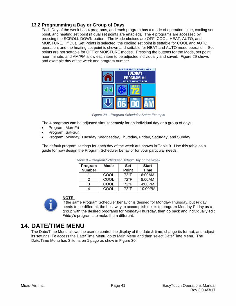
Micro-Air, Inc. Page 41 EasyTouch Operations Manual Rev 3.0 4/3/17
13.2 Programming a Day or Group of Days Each Day of the week has 4 programs, and each program has a mode of operation, time, cooling set point, and heating set point (if dual set points are enabled). The 4 programs are accessed by pressing the SCROLL DOWN button. The Mode choices are OFF, COOL, HEAT, AUTO, and MOISTURE. If Dual Set Points is selected, the cooling set point is settable for COOL and AUTO operation, and the heating set point is shown and settable for HEAT and AUTO mode operation. Set points are not settable for OFF or MOISTURE modes. Pressing the buttons for the Mode, set point, hour, minute, and AM/PM allow each item to be adjusted individually and saved. Figure 29 shows and example day of the week and program number.
Figure 29 – Program Scheduler Setup Example
The 4 programs can be adjusted simultaneously for an individual day or a group of days:
Program: Mon-Fri
Program: Sat-Sun
Program: Monday, Tuesday, Wednesday, Thursday, Friday, Saturday, and Sunday The default program settings for each day of the week are shown in Table 9. Use this table as a guide for how design the Program Scheduler behavior for your particular needs.
Table 9 – Program Scheduler Default Day of the Week
Program Number
Mode Set Point
Start Time
1 COOL 72°F 6:00AM
2 COOL 72°F 8:00AM
3 COOL 72°F 4:00PM
4 COOL 72°F 10:00PM
NOTE: If the same Program Scheduler behavior is desired for Monday-Thursday, but Friday needs to be different, the best way to accomplish this is to program Monday-Friday as a group with the desired programs for Monday-Thursday, then go back and individually edit Friday’s programs to make them different.
14. DATE/TIME MENU The Date/Time Menu allows the user to control the display of the date & time, change its format, and adjust its settings. To access the Date/Time Menu, go to Main Menu and then select Date/Time Menu. The Date/Time Menu has 3 items on 1 page as show in Figure 30.
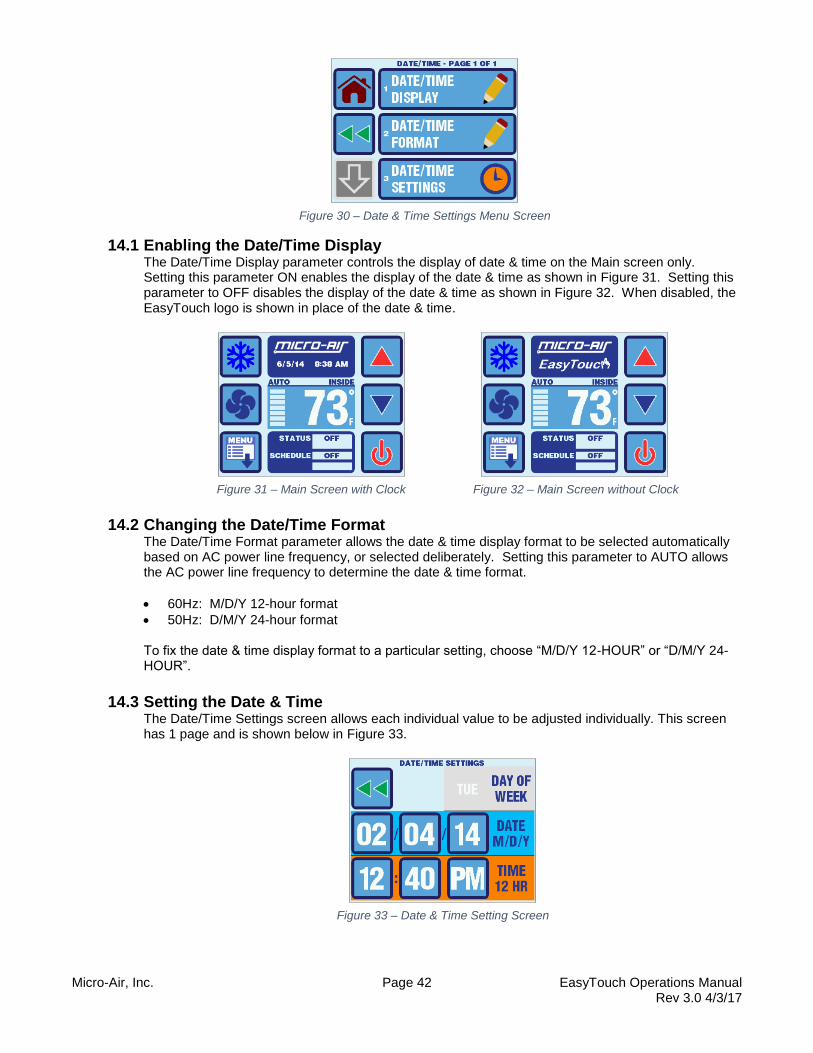
Micro-Air, Inc. Page 42 EasyTouch Operations Manual Rev 3.0 4/3/17
Figure 30 – Date & Time Settings Menu Screen
14.1 Enabling the Date/Time Display The Date/Time Display parameter controls the display of date & time on the Main screen only. Setting this parameter ON enables the display of the date & time as shown in Figure 31. Setting this parameter to OFF disables the display of the date & time as shown in Figure 32. When disabled, the EasyTouch logo is shown in place of the date & time.
Figure 31 – Main Screen with Clock Figure 32 – Main Screen without Clock
14.2 Changing the Date/Time Format The Date/Time Format parameter allows the date & time display format to be selected automatically based on AC power line frequency, or selected deliberately. Setting this parameter to AUTO allows the AC power line frequency to determine the date & time format.
60Hz: M/D/Y 12-hour format
50Hz: D/M/Y 24-hour format To fix the date & time display format to a particular setting, choose “M/D/Y 12-HOUR” or “D/M/Y 24-HOUR”.
14.3 Setting the Date & Time The Date/Time Settings screen allows each individual value to be adjusted individually. This screen has 1 page and is shown below in Figure 33.
Figure 33 – Date & Time Setting Screen

Micro-Air, Inc. Page 43 EasyTouch Operations Manual Rev 3.0 4/3/17
To edit a particular value, press the button corresponding to the value. After making the necessary adjustments in the edit screen, press the SAVE button. The day of the week will automatically be calculated based upon the set date.
NOTE: If the EasyTouch battery is ever replaced or the rechargeable battery becomes fully discharged, the date & time settings will be reset to 01/01/2007 12:00AM. During an AC power-up under these conditions, the EasyTouch will detect this date & time reset and will display the Date/Time Settings screen immediately after power-up.
15. SYSTEM MENU The System menu allows the user to view and modify system settings pertaining to the display itself. For example, the screen brightness, colors, Sleep Mode behaviors, display lock, etc. To access the System Menu, go to Main Menu and then select System Menu. The System Menu has 6 items on 2 pages as show in Figure 34.
Figure 34 – System Settings Menu Screens
15.1 Firmware Version The Firmware Version is displayed on the System Menu screen inside the corresponding button. Pressing the button will display a screen showing the firmware version number and its release date.
15.2 Display Setup The Display Setup menu allows the adjustment of the display brightness, and the color adjustment of 5 different portions of the display color scheme. The Display Setup menu has 6 items on 2 pages as shown in Figure 35.
Figure 35 – Display Setup Menu Screens
Display Brightness – This setting can be adjusted from 5 to 100%. Note that this setting does not affect the brightness used during sleep mode or during power up. Display Colors – The various portions of the display can have their colors changed. The color choice palettes displayed consist of 126 different colors shown across 14 pages. Pages 1-12 show the color choices from a standard color pallet, page 13 shows the grayscale color choices, and page 14 shows the standard display colors used by factory default. Figure 36 below shows an example of a color selection display screen.

Micro-Air, Inc. Page 44 EasyTouch Operations Manual Rev 3.0 4/3/17
Figure 36 – Color Edit Screen Example
15.3 Sleep Mode Settings The Sleep Mode Settings menu allows control over all the various Sleep Mode displays and its behavior. The Sleep Mode Settings menu has 5 items on 2 pages as shown in Figure 37.
Figure 37 – Sleep Mode Settings Menu Screens
Sleep Mode Display - Sleep Mode Display Allows to select among 5 different options to be displayed when the EasyTouch automatically enters into Sleep Mode.
Standard Logo – shown in Figure 3
Blank Screen Backlight On
Blank Screen Backlight Off
Custom Logo – see details below.
Custom Text – see editor below. Sleep Mode Delay – The Sleep Mode Delay parameter is set to 60 seconds by default. That is, after 60 seconds of no touch screen interactions, the EasyTouch will automatically enter Sleep Mode. The choices for the Sleep Mode Delay parameter are OFF, and 0 to 600 seconds. If OFF is selected, the display will not go into Sleep Mode. Sleep Mode Text Edit – This special entry screen shown in Figure 38 allows the editing of the text string that will be displayed in Sleep Mode when “Custom Text” is selected as the Sleep Mode Display parameter.
Figure 38 – Sleep Mode Text Editor
The active (last) character can be changed using the UP and DOWN buttons. The character choices are as follows:

Micro-Air, Inc. Page 45 EasyTouch Operations Manual Rev 3.0 4/3/17
ABCDEFGHIJKLMNOPQRSTUVWXYZ0123456789&'*@:,°=!-()%.+#?/ (and a space character)
Navigating to the right is accomplished using the RIGHT ARROW button. Navigating to the left is accomplished using the DEL button. CLR deletes all the custom text except for one active character. The font size can be adjusted to 3 different sizes by pressing the font button. The total number of characters that will fit on the screen is a function of the font size, with an absolute max of 25. Pressing the SAVE button will store the updated Sleep Mode Text into non-volatile memory. Sleep Mode Text Color – The color of the Sleep Mode custom text can be adjusted identically as the other various display colors. See the description for Display Colors in section 15.2 for more information about adjusting and selection colors. Download Custom Logo - This feature button is normally grayed out unless the EasyTouch detects that the special programming cable is plugged into its 8-pin jack. Figure 39 shows the Down Custom Logo screen as it normally appears before a download is initiated.
Figure 39 – Sleep Custom Logo Download Screen
Use of this feature also requires a special USB programming cable (SUB-082-X00) and special PC software that enables the reading of a 24-bit graphics bitmap file (BMP) and then transmission to the EasyTouch. The PC software can be downloaded free from the EasyTouch product page on the Micro-Air website (www.microair.net). Please contact Micro-Air Customer Service for more information on this special programming cable and PC program (Micro-Air p/n SUB-082-X00).
15.4 Display Lock The Display Lock menu allows control over the Display Lock and its 4-digit PIN. The Display Lock menu has 2 options on 1 page as shown in Figure 40.
Figure 40 – Display Lock Menu Screen
NOTE: The EasyTouch factory default PIN is 1234.
Set Access Locked by PIN – This parameter controls the display access level at which PIN access is required. There are 5 levels of access restriction including OFF (no restriction), each of which is a progressively higher (earlier) in the access allowed:

Micro-Air, Inc. Page 46 EasyTouch Operations Manual Rev 3.0 4/3/17
None (no lock or restriction, factory default)
Control Parameters – access without the PIN is allowed to the Home & Main screens, and to all menus and settings except for the Control Parameters and all sub-menus and parameters beyond this point.
All Menu Settings – access without the PIN is allowed to the Home and Main Screens, but no access to the Main Menu is allowed and all sub-menus and parameters beyond this point.
Main Screen – access without the PIN is allowed to the Home Screen, but no access is allowed beyond this point.
Home Screen – access without the PIN allows viewing the Home Screen after power up or exiting from Sleep Mode, but not button presses or access beyond this point is allowed.
When access to a restricted point is attempted, the EasyTouch will prompt the user for the PIN with the display screen shown in Figure 41. The factory default PIN for the EasyTouch is 1234.
Figure 41 – Display Lock PIN Prompt Screen
Figure 42 shows examples of the screen displays when the PIN is entered correctly or incorrectly. If the PIN is entered incorrectly, the CLR button must be pressed in order to try again.
Figure 42 – Display Lock PIN Entry Screen Examples
Once the PIN is entered successfully, access to all levels below and above are allowed, until the display once again enters Sleep Mode or until its AC power is cycled. PIN re-entry will also be required again if the access level parameter setting is changed. Change PIN – This option allows the PIN setting to be changed to a different 4-digit value. Before entering a new PIN, the current PIN must be entered first. Once a new 4-digit PIN is entered and validated, the screen color will change to green and the ENT button will be displayed as shown in Figure 43. Pressing the ENT button will save the new PIN into non-volatile memory.

Micro-Air, Inc. Page 47 EasyTouch Operations Manual Rev 3.0 4/3/17
Figure 43 – Display Lock PIN Change Display Screen
IMPORTANT: If the PIN is forgotten, it can be restored to 1234 by powering off the control at the AC circuit breaker, removing the battery for 30 seconds, reinstalling, and powering back up. This will only reset the date and time to its factory default and will also reset the PIN to 1234. No other parameters or saved entries will be lost.
15.5 Cleaning Mode The Cleaning Mode Allows screen to be cleaned for 30 seconds with the backlight turned off and the touch panel disabled. In this way, finger prints and other dirt can be seen more clearly and the touch screen will not react to the wiping. The screen and touch panel will turn on again automatically in 30 seconds. Normal system operation is not affected during this time. Micro-Air recommends that a soft, non-abrasive cloth be used with a small amount of rubbing alcohol to clean the display.
15.6 Wi-Fi Settings (optional EasyTouch feature) The Wi-Fi Settings Menu allows the editing of the various Wi-Fi SSID, password, and IP address settings. Also, the detailed live status of the Wi-Fi connection can also be viewed. This menu will only be selectable if the EasyTouch has the optional Wi-Fi hardware feature installed. The Wi-Fi Settings Menu consists of 7 items on 3 pages as shown in Figure 44.
Figure 44 – Wi-Fi Settings Menu Screens
Network Status -.The Network Status screen displays the current network connection status, signal strength, DHCP configuration, and IP addresses as shown in Figure 45.

Micro-Air, Inc. Page 48 EasyTouch Operations Manual Rev 3.0 4/3/17
Figure 45 – Wi-Fi Network Status Screen
Network Name (SSID) & Password – The Wi-Fi Network Name (SSID) and Password can be set via the screen shown in Figure 46. If the network does not use a password, the password setting does not matter and can be left at any value (e.g. space).
Figure 46 – Wi-Fi Network Name (SSID) & Password Screens
Network DHCP On/Off – DHCP can be enabled or disabled via this setting. If enabled, the Network Static IP, Gateway, and Subnet mask settings are not used. If disabled, then these additional settings must be configured properly for your Wi-Fi network. Network Static IP/Gateway/Subnet Mask – These settings only apply if the DHCP is set to ON (enabled). They can be set via the screen shown in Figure 47.
Figure 47 – Wi-Fi Network IP Address Screens
16. TROUBLESHOOT & COMMISSION MENU The Troubleshoot & Commission Menu allows access to the System Status, Help, and the Commission Procedure. To access the Troubleshoot & Commission Menu, go to Main Menu and then select Troubleshoot & Commission. The Troubleshoot & Commission Menu has 3 items on 1 page as show in Figure 48.
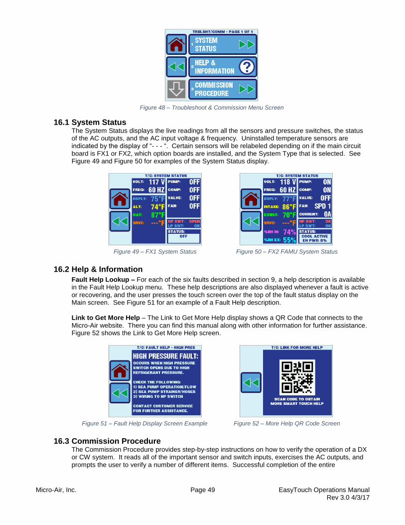
Micro-Air, Inc. Page 49 EasyTouch Operations Manual Rev 3.0 4/3/17
Figure 48 – Troubleshoot & Commission Menu Screen
16.1 System Status The System Status displays the live readings from all the sensors and pressure switches, the status of the AC outputs, and the AC input voltage & frequency. Uninstalled temperature sensors are indicated by the display of “- - - “. Certain sensors will be relabeled depending on if the main circuit board is FX1 or FX2, which option boards are installed, and the System Type that is selected. See Figure 49 and Figure 50 for examples of the System Status display.
Figure 49 – FX1 System Status Figure 50 – FX2 FAMU System Status
16.2 Help & Information
Fault Help Lookup – For each of the six faults described in section 9, a help description is available in the Fault Help Lookup menu. These help descriptions are also displayed whenever a fault is active or recovering, and the user presses the touch screen over the top of the fault status display on the Main screen. See Figure 51 for an example of a Fault Help description. Link to Get More Help – The Link to Get More Help display shows a QR Code that connects to the Micro-Air website. There you can find this manual along with other information for further assistance. Figure 52 shows the Link to Get More Help screen.
Figure 51 – Fault Help Display Screen Example Figure 52 – More Help QR Code Screen
16.3 Commission Procedure The Commission Procedure provides step-by-step instructions on how to verify the operation of a DX or CW system. It reads all of the important sensor and switch inputs, exercises the AC outputs, and prompts the user to verify a number of different items. Successful completion of the entire

Micro-Air, Inc. Page 50 EasyTouch Operations Manual Rev 3.0 4/3/17
Commission Procedure will add an entry into the Fault History to provide a record that the procedure was carried out. See Figure 53 for examples of the Commission Procedure display screens.
Figure 53 – Commission Procedure Screen Examples
17. FAULT HISTORY & RUN HOURS MENU The Fault History & Run Hours Menu allows access to the Fault History and Run Hour displays. To access the Fault History & Run Hours Menu, go to Main Menu and then select Fault History & Run Hours. The Fault History & Runs Hours Menu has 3 items on 1 page as show in Figure 54.
Figure 54 – Fault History & Run Hours Menu Screen
17.1 Fault History The Fault History displays the all of the faults that have occurred. Each entry has a number, date & time, and a fault type as shown in Figure 55. The most recent entries are shown at the top of the list with the lowest entry number. For example, entry #1 is the most recently recorded fault and entries #2, #3, #4, etc. all occurred before entry #1. The Fault History can store a maximum of 500 faults. Once filled, it will begin overwriting the oldest entry in the history; however, the order of the display and the numbering of the entries will always be maintained as described above. All of the fault types described in section 9 are captured in the Fault History. Refer to that section for further details on the each fault type. In addition, the execution of the Commission Procedure is also recorded (see section 16.3). To clear the fault history, press and release the CLR button. You will then be prompted to enter the Display Lock PIN (see section 15.4). After correctly entering the PIN, press and release the CLR button again to clear the Fault History. Pressing and holding the CLR button for 5 seconds will restore the Fault History to the listing of lifetime faults stored in the 500-entry memory. Although the displayed Fault History can be cleared, the lifetime entries are always being maintained in the background and cannot be cleared (for a maximum of the previous 500 entries).

Micro-Air, Inc. Page 51 EasyTouch Operations Manual Rev 3.0 4/3/17
Figure 55 – Fault History Display Screen
NOTE: The Fault History is an excellent troubleshooting tool and can only have maximum effectiveness if the Date & Time are set correctly. See section 14 for more information on how to properly set the Date & Time.
17.2 Compressor Run Hours The Compressor Run Hours displays the number of hours the fan has been operating as shown in Figure 56. The value can be cleared by pressing the CLR button. You will then be prompted to enter the Display Lock PIN (see section 15.4). After correctly entering the PIN, press and release the CLR button again to clear the run hours. Once cleared, the number of operating hours begins accumulating again from 0. Pressing and holding the CLR button for 10 seconds will reset the Compressor Run Hours to the total hours accumulated for the lifetime of the display. Although the displayed hours are cleared, the lifetime hours are always being maintained in the background and cannot be cleared.
Figure 56 – Compressor Run Hours Display Figure 57 – Fan Run Hours Display
17.3 Fan Run Hours The Fan Run Hours displays the number of hours the fan has been operating as shown in Figure 57. The value can be cleared by pressing the CLR button. You will then be prompted to enter the Display Lock PIN (see section 15.4). After correctly entering the PIN, press and release the CLR button again to clear the run hours. Once cleared, the number of operating hours begins accumulating again from 0. Pressing and holding the CLR button for 10 seconds will reset the Fan Run Hours to the total hours accumulated for the lifetime of the display. Although the displayed hours are cleared, the lifetime hours are always being maintained in the background and cannot be cleared.
NOTE: The Fan Run Hours display is a completely separate timer value maintained and stored separately from the Filter Reminder (Fan) Hours. The two timers are completely independent. See section 12.1.6 for more information on the Filter Reminder.

Micro-Air, Inc. Page 52 EasyTouch Operations Manual Rev 3.0 4/3/17
18. SPECIFICATIONS OPERATIONAL Set Point Operating Range (single) .......................................................... 65°F to 85°F (18°C to 30°C) Set Point Operating Range (dual, cool mode) .......................................... 65°F to 95°F (18°C to 35°C) Set Point Operating Range (dual, heat mode) ......................................... 55°F to 85°F (13°C to 30°C) Ambient Temperature Operating Range Displayed ............................... 5°F to 150°F (-15°C to 65°C) Sensor Accuracy ................................................................................. ± 2°F @ 77°F (±1.0°C @ 25°C) Low Voltage Processor Reset .................................................................................................. 50 VAC Line Voltage ................................................................................................................. 100 to 240 VAC Frequency ........................................................................................................................... 50 or 60 Hz Fan Output ............................................................................................................ 6 Amps @ 115 VAC Fan Output ............................................................................................................... Amps @ 230 VAC Valve Output ................................................................................................. 1/4 Amp @ 115/230 VAC Heater Output (using valve relay) ....................................................................... 15 Amps @ 115 VAC Heater Output (using valve relay) ............................................................................ 10 Amps @ 230 V Pump Output .......................................................................................................... 1/4 HP @ 115 VAC Pump Output .......................................................................................................... 1/2 HP @ 230 VAC Compressor Output ................................................................................................... 1 HP @ 115 VAC Compressor Output ................................................................................................... 2 HP @ 230 VAC Minimum Operating Temperature ....................................................................................... 0°F (-18°C) Maximum Ambient Operating Temperature..................................................................... 180°F (82°C) Maximum Rh Conditions .................................................................................... 99% Non-Condensing Power Consumption ................................................................................................ Less Than 5 Watts
DIMENSIONS Display Panel ................................................................................... 4.309” (109mm) X 2.874" (73mm) Panel Cut Out ......................................................................................2.90" (74mm) X 2.165" (55mm) Bezel Type Required .................................................................. Vimar® Eikon or Vimar® Eikon EVO
CABLE LENGTHS Display Cable Self Contained ................................................................................ 15' (4.6m) Standard Display Cable Split System .................................................................................... 30' (9.1m) Standard Maximum Display Cable Length ......................................................................... 75' (22.9m) Maximum Alternate Air Sensor (optional) ................................................................................. 7' (2.1m) Standard Alternate Air Sensor Split System (optional) ......................................................... 30' (9.1m) Standard Outside Air Sensor (optional) ................................................................................. 15' (4.6m) Standard Maximum Temperature Sensor Cable Length .................................................... 75' (22.9m) Maximum Combo Temperature/Humidity Sensor (optional for FX2 only) ............................... 7' (2.1m) Standard Maximum Combo Inside Temperature/Humidity Sensor Cable Length ............... 30' (9.1m) Maximum
SYSTEM INPUTS Inside Air Temperature Sensor (built into display) ............................................................................... 1 High Refrigerant Pressure ................................................................................................................... 1 Low Refrigerant Pressure (optional) .................................................................................................... 1 Alternate Air Temperature Sensor (optional) ....................................................................................... 1 Combo Temperature/Humidity Sensor (optional for FX2 only) ........................................................... 1 Outside Air Temperature Sensor (optional) ......................................................................................... 1 Pump Sentry Condenser Coil Sensor (optional) .................................................................................. 1

Micro-Air, Inc. Page 53 EasyTouch Operations Manual Rev 3.0 4/3/17
19. WARRANTY AGREEMENT Micro-Air warrants new products sold to be free from manufacturing defects for a period of two (2) years commencing with delivery of the product to the original customer. Our obligation under this warranty is expressly limited at our option, to the replacement or the repair at Micro-Air or at a service facility designated by us, of such parts, as inspection shall disclose to have been defective. This warranty does not apply to defects caused by damage or unreasonable use, including failure to provide reasonable and necessary maintenance, while in the possession of the consumer. Micro-Air shall not be liable for consequential damages of any kind, including, but not limited to, consequential labor costs or transportation charges in connection with the replacement or repair of the defective parts.