eaton cutler-hammer- operator interface products
TRANSCRIPT
CA08104001E For more information visit:
www.EatonElectrical.com
June 2006
Contents
Operator Interface Panels & Automation Products 35.0-1
22
23
24
25
26
27
28
29
30
31
32
33
34
35
36
37
38
39
40
41
42
43
Sheet 1551
Op
era
tor
Inte
rface
Pan
els
& A
uto
mati
on
Pro
du
cts
Operator Interface Panels & Automation Products
Product Family Overview
Product Description . . . . . . . . . . . . . . . . . . . . . . . . . . . . . . . . . . . . . . . . . . .
35.0-2
PanelMate Technology Benefits . . . . . . . . . . . . . . . . . . . . . . . . . . . . . . . . .
35.0-2
How to Order . . . . . . . . . . . . . . . . . . . . . . . . . . . . . . . . . . . . . . . . . . . . . . . .
35.0-2
PanelMate
T
Operator Interface
PanelMate Power Pro Overview . . . . . . . . . . . . . . . . . . . . . . . . . . . . . . . . .
35.1-1
PanelMate Power Pro LT 1100, 1700, 3000 and 5000 . . . . . . . . . . . . . . . .
35.1-2
PanelMate ePro
E
. . . . . . . . . . . . . . . . . . . . . . . . . . . . . . . . . . . . . . . . . . . . .
35.1-3
PanelMate ePro ES. . . . . . . . . . . . . . . . . . . . . . . . . . . . . . . . . . . . . . . . . . . .
35.1-4
PanelMate ePro PS. . . . . . . . . . . . . . . . . . . . . . . . . . . . . . . . . . . . . . . . . . . .
35.1-5
PanelMate Flat Panel Displays . . . . . . . . . . . . . . . . . . . . . . . . . . . . . . . . . .
35.1-8
PanelMate PC Pro. . . . . . . . . . . . . . . . . . . . . . . . . . . . . . . . . . . . . . . . . . . . .
35.1-9
PanelMate Software
PanelMate Configuration Software . . . . . . . . . . . . . . . . . . . . . . . . . . . . . .
35.2-1
ePro Software Suite . . . . . . . . . . . . . . . . . . . . . . . . . . . . . . . . . . . . . . . . . . .
35.2-2
PanelMate Communications . . . . . . . . . . . . . . . . . . . . . . . . . . . . . . . . . . . .
35.2-3
Connectivity: Utilities, Interfaces & Cables
Communication Utilities and Connectivity . . . . . . . . . . . . . . . . . . . . . . . .
35.3-1
Accessories
. . . . . . . . . . . . . . . . . . . . . . . . . . . . . . . . . . . . . . . . . . . . . . . . . . . .
35.4-1
Application Information
General Application Information . . . . . . . . . . . . . . . . . . . . . . . . . . . . . . . .
35.5-1
Enclosure Information . . . . . . . . . . . . . . . . . . . . . . . . . . . . . . . . . . . . . . . . .
35.5-2
Communication Interface . . . . . . . . . . . . . . . . . . . . . . . . . . . . . . . . . . . . . .
35.5-4
PanelMate Unit Dimensions . . . . . . . . . . . . . . . . . . . . . . . . . . . . . . . . . . . .
35.5-8
PanelMate ePro Unit Dimensions . . . . . . . . . . . . . . . . . . . . . . . . . . . . . . . .
35.5-12
Flat Panel Unit Dimensions . . . . . . . . . . . . . . . . . . . . . . . . . . . . . . . . . . . . .
35.5-15
PanelMate ePro ES Unit Dimensions . . . . . . . . . . . . . . . . . . . . . . . . . . . . .
35.5-18
PanelMate ePro PS Unit Dimensions . . . . . . . . . . . . . . . . . . . . . . . . . . . . .
35.5-19
Specifications
See Eaton’s Cutler-Hammer Product Specification Guide on enclosed CD-ROM:1995 CSI Format: . . . . . . . . . . . . . . . . . . . . . . . . . . . . . . . . . . . . . . . .
Section 16902
2004 CSI Format: . . . . . . . . . . . . . . . . . . . . . . . . . . . . . . . . . . . . . . . .
Section 26 29 05
PanelMate Operator Interface
35.0-2
For more information visit:
www.EatonElectrical.com
CA08104001E
June 2006
Operator Interface Panels & Automation Products
22
23
24
25
26
27
28
29
30
31
32
33
34
35
36
37
38
39
40
41
42
43
Product Family Overview
PanelMate — Product Description
Sheet 1552
PanelMate
Product Description
Machine builders and manufacturing system designers increasingly recog-nize the benefits of using electronic operator interface devices to replace pushbuttons, lights, gauges and other traditional hardwired devices.
Most choose dedicated operator inter-face systems because they are easy to use, fully integrated and cost-effective.
PanelMate: The Industry Standard
PanelMate units are flexible, expand-able, cost-effective alternatives to tra-ditional
operator control panels. A single PanelMate
unit easily replaces panels that once contained numerous push-buttons, indicator lights, thumbwheels,
message displays and alarm annunciators.
PanelMate Technology Benefits
■
Replaces conventional control panels at less than half the cost.
■
Gives operators more information for better control decisions.
■
Standardizes operator stations and minimizes operator training.
■
Saves processor memory by utilizing Boolean logic and math functions.
■
Reduces hardwiring costs and minimizes installation time.
■
Adds advanced capabilities such as machine diagnostics, troubleshooting,
trending and alarms at no additional cost.
■
Automates documentation.
■
Meets tight panel space requirements.
How to Order
PanelMate System Components
Each PanelMate system requires component selection from three major categories:
■
Operator Interface — the online unit or operator station.
■
Configuration Software — PC-based software, used to configure and trans-fer applications to and from the Operator Interface.
■
Connectivity — includes optional cables, hardware interfaces and software utilities.
Selection Criteria
■
First, select the most appropriate Operator Interface, Display Type and Size, and Operator Input options for the customer’s application.
❑
The selection of the Operator Interface model line is driven by such considerations as the size and complexity of the operator interface application, performance requirements, as well as the eco-nomic factors of the overall control system.
❑
The Display Type is chosen based on the operator’s needs — text only, text and graphics, color or grayscale. Display Size is selected based on application complexity and the operator’s proximity to the Operator Interface.
❑
Operator Input options include either touchpanel (keypad) or touchscreen Operator Interface models. Criteria for selection of the best input method include environmental factors (airborne particles, grease, etc.), and appli-cation design (numeric input, one-touch control, etc.).
■
Second, select the appropriate configuration editing software for the chosen Operator Interface.
Note:
If the customer already has config-uration software, they may only need a software upgrade.
■
Finally, select required connectivity features, such as interface cables, optional high-speed interface cards, and, for some Allen-Bradley
T
drivers, licensing enabler utilities.Eaton’s Cutler-Hammer
T
interface cables are ideal for system and application testing. For actual plant floor applications, custom cables are generally required to meet the customer’s requirements for length, environment, termination, etc.
Note:
In order to specify the proper cabling and other connectivity options, you must know the target PLC or control-ler to be used with the Operator Inter-face. Required information may include the PLC brand, Model Number, software/firmware revision level, and hardware/software interface type.
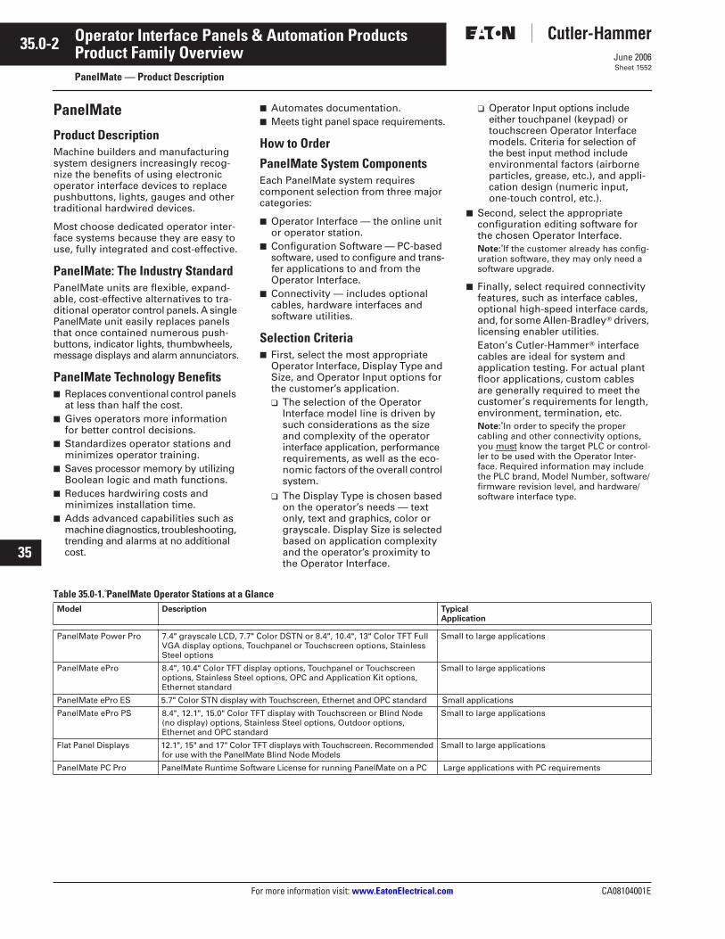
Table 35.0-1. PanelMate Operator Stations at a Glance
Model Description TypicalApplication
PanelMate Power Pro 7.4" grayscale LCD, 7.7" Color DSTN or 8.4", 10.4", 13" Color TFT Full VGA display options, Touchpanel or Touchscreen options, Stainless Steel options
Small to large applications
PanelMate ePro 8.4", 10.4" Color TFT display options, Touchpanel or Touchscreen options, Stainless Steel options, OPC and Application Kit options, Ethernet standard
Small to large applications
PanelMate ePro ES 5.7" Color STN display with Touchscreen, Ethernet and OPC standard Small applications
PanelMate ePro PS 8.4", 12.1", 15.0" Color TFT display with Touchscreen or Blind Node (no display) options, Stainless Steel options, Outdoor options, Ethernet and OPC standard
Small to large applications
Flat Panel Displays 12.1", 15" and 17" Color TFT displays with Touchscreen. Recommended for use with the PanelMate Blind Node Models
Small to large applications
PanelMate PC Pro PanelMate Runtime Software License for running PanelMate on a PC Large applications with PC requirements
CA08104001E For more information visit:
www.EatonElectrical.com
35.1-1
June 2006
Operator Interface Panels & Automation Products
22
23
24
25
26
27
28
29
30
31
32
33
34
35
36
37
38
39
40
41
42
43
PanelMate Operator Interface
General Description — PanelMate Power Pro
Sheet 1553
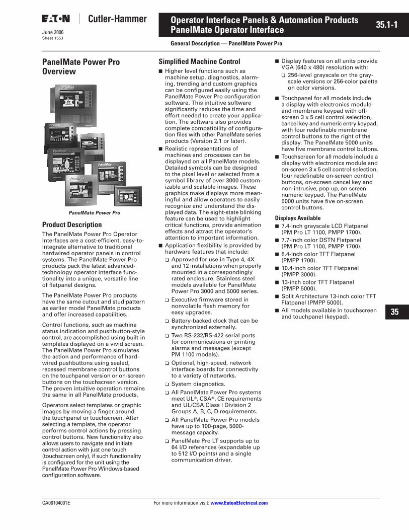
PanelMate Power Pro Overview
PanelMate Power Pro
Product Description
The PanelMate Power Pro Operator Interfaces are a cost-efficient, easy-to-integrate alternative to traditional hardwired operator panels in control systems. The PanelMate Power Pro products pack the latest advanced-technology operator interface func-tionality into a unique, versatile line of flatpanel designs.
The PanelMate Power Pro products have the same cutout and stud pattern as earlier model PanelMate products and offer increased capabilities.
Control functions, such as machine status indication and pushbutton-style control, are accomplished using built-in templates displayed on a vivid screen. The PanelMate Power Pro simulates the action and performance of hard-wired pushbuttons using sealed, recessed membrane control buttons on the touchpanel version or on-screen buttons on the touchscreen version. The proven intuitive operation remains the same in all PanelMate products.
Operators select templates or graphic images by moving a finger around the touchpanel or touchscreen. After selecting a template, the operator performs control actions by pressing control buttons. New functionality also allows users to navigate and initiate control action with just one touch (touchscreen only), if such functionality is configured for the unit using the PanelMate Power Pro Windows-based configuration software.
Simplified Machine Control
■
Higher level functions such as machine setup, diagnostics, alarm-ing, trending and custom graphics can be configured easily using the PanelMate Power Pro configuration software. This intuitive software significantly reduces the time and effort needed to create your applica-tion. The software also provides complete compatibility of configura-tion files with other PanelMate series products (Version 2.1 or later).
■
Realistic representations of machines and processes can be displayed on all PanelMate models. Detailed symbols can be designed to the pixel level or selected from a symbol library of over 3000 custom-izable and scalable images. These graphics make displays more mean-ingful and allow operators to easily recognize and understand the dis-played data. The eight-state blinking feature can be used to highlight critical functions, provide animation effects and attract the operator’s attention to important information.
■
Application flexibility is provided by hardware features that include:
❑
Approved for use in Type 4, 4X and 12 installations when properly mounted in a correspondingly rated enclosure. Stainless steel models available for PanelMate Power Pro 3000 and 5000 series.
❑
Executive firmware stored in nonvolatile flash memory for easy upgrades.
❑
Battery-backed clock that can be synchronized externally.
❑
Two RS-232/RS-422 serial ports for communications or printing alarms and messages (except PM 1100 models).
❑
Optional, high-speed, network interface boards for connectivity to a variety of networks.
❑
System diagnostics.
❑
All PanelMate Power Pro systems meet UL
T
, CSA
T
, CE requirements and UL/CSA Class I Division 2 Groups A, B, C, D requirements.
❑
All PanelMate Power Pro models have up to 100-page, 5000-message capacity.
❑
PanelMate Pro LT supports up to 64 I/O references (expandable up to 512 I/O points) and a single communication driver.
■
Display features on all units provide VGA (640 x 480) resolution with:
❑
256-level grayscale on the gray-scale versions or 256-color palette on color versions.
■
Touchpanel for all models include a display with electronics module and membrane keypad with off-screen 3 x 5 cell control selection, cancel key and numeric entry keypad, with four redefinable membrane control buttons to the right of the display. The PanelMate 5000 units have five membrane control buttons.
■
Touchscreen for all models include a display with electronics module and on-screen 3 x 5 cell control selection, four redefinable on-screen control buttons, on-screen cancel key and non-intrusive, pop-up, on-screen numeric keypad. The PanelMate 5000 units have five on-screen control buttons.
Displays Available
■
7.4-inch grayscale LCD Flatpanel (PM Pro LT 1100, PMPP 1700).
■
7.7-inch color DSTN Flatpanel (PM Pro LT 1100, PMPP 1700).
■
8.4-inch color TFT Flatpanel (PMPP 1700).
■
10.4-inch color TFT Flatpanel(PMPP 3000).
■
13-inch color TFT Flatpanel (PMPP 5000).
■
Split Architecture 13-inch color TFT Flatpanel (PMPP 5000).
■
All models available in touchscreen and touchpanel (keypad).
35.1-2
For more information visit:
www.EatonElectrical.com
CA08104001E
June 2006
Operator Interface Panels & Automation Products
22
23
24
25
26
27
28
29
30
31
32
33
34
35
36
37
38
39
40
41
42
43
PanelMate Operator Interface
General Description — PanelMate Pro LT and Power Pro
Sheet 1554
PanelMate Pro LT 1100
Product Description
The PanelMate Pro LT 1100 is available with a 7.4-inch grayscale LCD or 7.7-inch color Dual Scan (DSTN) display with full VGA resolution and 256 shades/colors. Models are available with either touchscreen (acrylic) or touchpanel for operator input and can be mounted in a 4-inch deep enclosure. The PanelMate Pro LT 1100 supports applications with up to 64 I/O references and a single communication driver. The number of supported I/O references can be upgraded to 512 I/O points (done in blocks of 64 I/O points — see 1100TAG Options). The PanelMate Pro LT 1100 requires 24 Vdc power input.
Product Selection
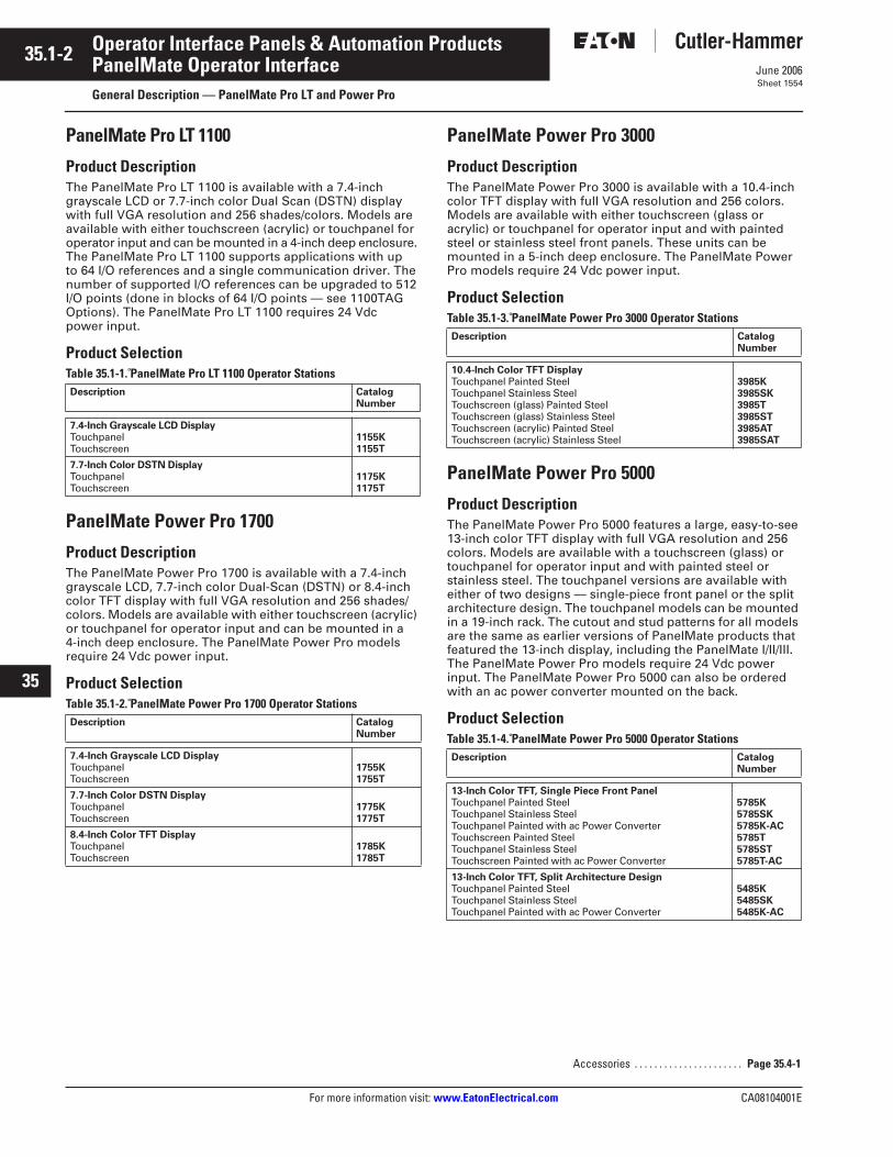
Table 35.1-1. PanelMate Pro LT 1100 Operator Stations
PanelMate Power Pro 1700
Product Description
The PanelMate Power Pro 1700 is available with a 7.4-inch grayscale LCD, 7.7-inch color Dual-Scan (DSTN) or 8.4-inch color TFT display with full VGA resolution and 256 shades/colors. Models are available with either touchscreen (acrylic) or touchpanel for operator input and can be mounted in a 4-inch deep enclosure. The PanelMate Power Pro models require 24 Vdc power input.
Product Selection
Table 35.1-2. PanelMate Power Pro 1700 Operator Stations
PanelMate Power Pro 3000
Product Description
The PanelMate Power Pro 3000 is available with a 10.4-inch color TFT display with full VGA resolution and 256 colors. Models are available with either touchscreen (glass or acrylic) or touchpanel for operator input and with painted steel or stainless steel front panels. These units can be mounted in a 5-inch deep enclosure. The PanelMate Power Pro models require 24 Vdc power input.
Product Selection
Table 35.1-3. PanelMate Power Pro 3000 Operator Stations
PanelMate Power Pro 5000
Product Description
The PanelMate Power Pro 5000 features a large, easy-to-see 13-inch color TFT display with full VGA resolution and 256 colors. Models are available with a touchscreen (glass) or touchpanel for operator input and with painted steel or stainless steel. The touchpanel versions are available with either of two designs — single-piece front panel or the split architecture design. The touchpanel models can be mounted in a 19-inch rack. The cutout and stud patterns for all models are the same as earlier versions of PanelMate products that featured the 13-inch display, including the PanelMate I/II/III. The PanelMate Power Pro models require 24 Vdc power input. The PanelMate Power Pro 5000 can also be ordered with an ac power converter mounted on the back.
Product Selection
Table 35.1-4. PanelMate Power Pro 5000 Operator Stations
Description CatalogNumber
7.4-Inch Grayscale LCD Display
TouchpanelTouchscreen
1155K1155T
7.7-Inch Color DSTN Display
TouchpanelTouchscreen
1175K1175T
Description CatalogNumber
7.4-Inch Grayscale LCD Display
TouchpanelTouchscreen
1755K1755T
7.7-Inch Color DSTN Display
TouchpanelTouchscreen
1775K1775T
8.4-Inch Color TFT Display
TouchpanelTouchscreen
1785K1785T
Description CatalogNumber
10.4-Inch Color TFT Display
Touchpanel Painted SteelTouchpanel Stainless SteelTouchscreen (glass) Painted SteelTouchscreen (glass) Stainless SteelTouchscreen (acrylic) Painted SteelTouchscreen (acrylic) Stainless Steel
3985K3985SK3985T3985ST3985AT3985SAT
Description CatalogNumber
13-Inch Color TFT, Single Piece Front Panel
Touchpanel Painted SteelTouchpanel Stainless SteelTouchpanel Painted with ac Power ConverterTouchscreen Painted SteelTouchpanel Stainless SteelTouchscreen Painted with ac Power Converter
5785K5785SK5785K-AC5785T5785ST5785T-AC
13-Inch Color TFT, Split Architecture Design
Touchpanel Painted SteelTouchpanel Stainless SteelTouchpanel Painted with ac Power Converter
5485K5485SK5485K-AC
Accessories . . . . . . . . . . . . . . . . . . . . . .
Page 35.4-1
CA08104001E For more information visit:
www.EatonElectrical.com
35.1-3
June 2006
Operator Interface Panels & Automation Products
22
23
24
25
26
27
28
29
30
31
32
33
34
35
36
37
38
39
40
41
42
43
PanelMate Operator Interface
General Description — PanelMate ePro
Sheet 1555
PanelMate ePro
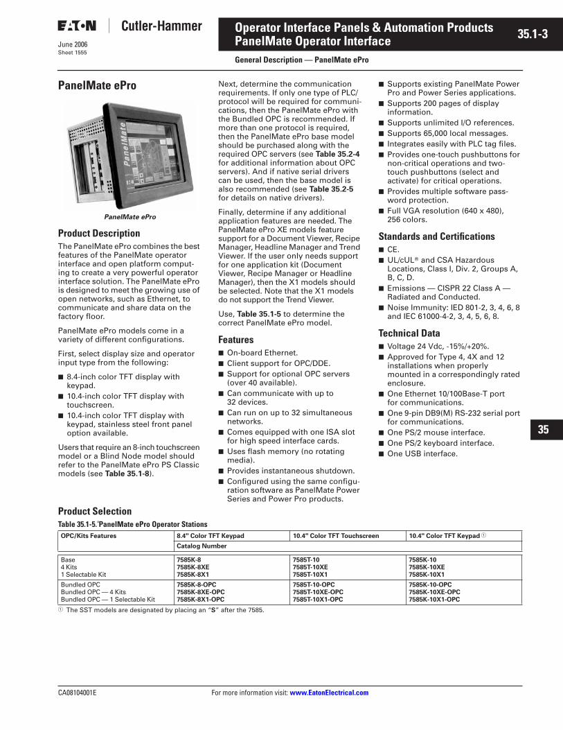
PanelMate ePro
Product Description
The PanelMate ePro combines the best features of the PanelMate operator interface and open platform comput-ing to create a very powerful operator interface solution. The PanelMate ePro is designed to meet the growing use of open networks, such as Ethernet, to communicate and share data on the factory floor.
PanelMate ePro models come in a variety of different configurations.
First, select display size and operator input type from the following:
■
8.4-inch color TFT display with keypad.
■
10.4-inch color TFT display with touchscreen.
■
10.4-inch color TFT display with keypad, stainless steel front panel option available.
Users that require an 8-inch touchscreen model or a Blind Node model should refer to the PanelMate ePro PS Classic models (see
Table 35.1-8
).
Next, determine the communication requirements. If only one type of PLC/protocol will be required for communi-cations, then the PanelMate ePro with the Bundled OPC is recommended. If more than one protocol is required, then the PanelMate ePro base model should be purchased along with the required OPC servers (see
Table 35.2-4
for additional information about OPC servers). And if native serial drivers can be used, then the base model is also recommended (see
Table 35.2-5
for details on native drivers).
Finally, determine if any additional application features are needed. The PanelMate ePro XE models feature support for a Document Viewer, Recipe Manager, Headline Manager and Trend Viewer. If the user only needs support for one application kit (Document Viewer, Recipe Manager or Headline Manager), then the X1 models should be selected. Note that the X1
models do not support the Trend Viewer.
Use,
Table 35.1-5
to determine the correct PanelMate ePro model.
Features
■
On-board Ethernet.
■
Client support for OPC/DDE.
■
Support for optional OPC servers (over 40 available).
■
Can communicate with up to 32 devices.
■
Can run on up to 32 simultaneous networks.
■
Comes equipped with one ISA slot for high speed interface cards.
■
Uses flash memory (no rotating media).
■
Provides instantaneous shutdown.
■
Configured using the same configu-ration software as PanelMate Power Series and Power Pro products.
■
Supports existing PanelMate Power Pro and Power Series applications.
■
Supports 200 pages of display information.
■
Supports unlimited I/O references.
■
Supports 65,000 local messages.
■
Integrates easily with PLC tag files.
■
Provides one-touch pushbuttons for non-critical operations and two-touch pushbuttons (select and activate) for critical operations.
■
Provides multiple software pass-word protection.
■
Full VGA resolution (640 x 480), 256 colors.
Standards and Certifications
■
CE.
■
UL/cUL
T
and CSA Hazardous Locations, Class I, Div. 2, Groups A, B, C, D.
■
Emissions — CISPR 22 Class A — Radiated and Conducted.
■
Noise Immunity: IED 801-2, 3, 4, 6, 8 and IEC 61000-4-2, 3, 4, 5, 6, 8.
Technical Data
■
Voltage 24 Vdc, -15%/+20%.
■
Approved for Type 4, 4X and 12 installations when properly mounted in a correspondingly rated enclosure.
■
One Ethernet 10/100Base-T port for communications.
■
One 9-pin DB9(M) RS-232 serial port for communications.
■
One PS/2 mouse interface.
■
One PS/2 keyboard interface.
■
One USB interface.
Product Selection
Table 35.1-5. PanelMate ePro Operator Stations
1
The SST models are designated by placing an “
S
” after the 7585.
OPC/Kits Features 8.4" Color TFT Keypad 10.4" Color TFT Touchscreen 10.4" Color TFT Keypad
1
Catalog Number
Base4 Kits1 Selectable Kit
7585K-87585K-8XE7585K-8X1
7585T-107585T-10XE7585T-10X1
7585K-107585K-10XE7585K-10X1
Bundled OPCBundled OPC — 4 KitsBundled OPC — 1 Selectable Kit
7585K-8-OPC7585K-8XE-OPC7585K-8X1-OPC
7585T-10-OPC7585T-10XE-OPC7585T-10X1-OPC
7585K-10-OPC7585K-10XE-OPC7585K-10X1-OPC
35.1-4
For more information visit:
www.EatonElectrical.com
CA08104001E
June 2006
Operator Interface Panels & Automation Products
22
23
24
25
26
27
28
29
30
31
32
33
34
35
36
37
38
39
40
41
42
43
PanelMate Operator Interface
General Description — PanelMate ePro ES
Sheet 1556
PanelMate ePro ES
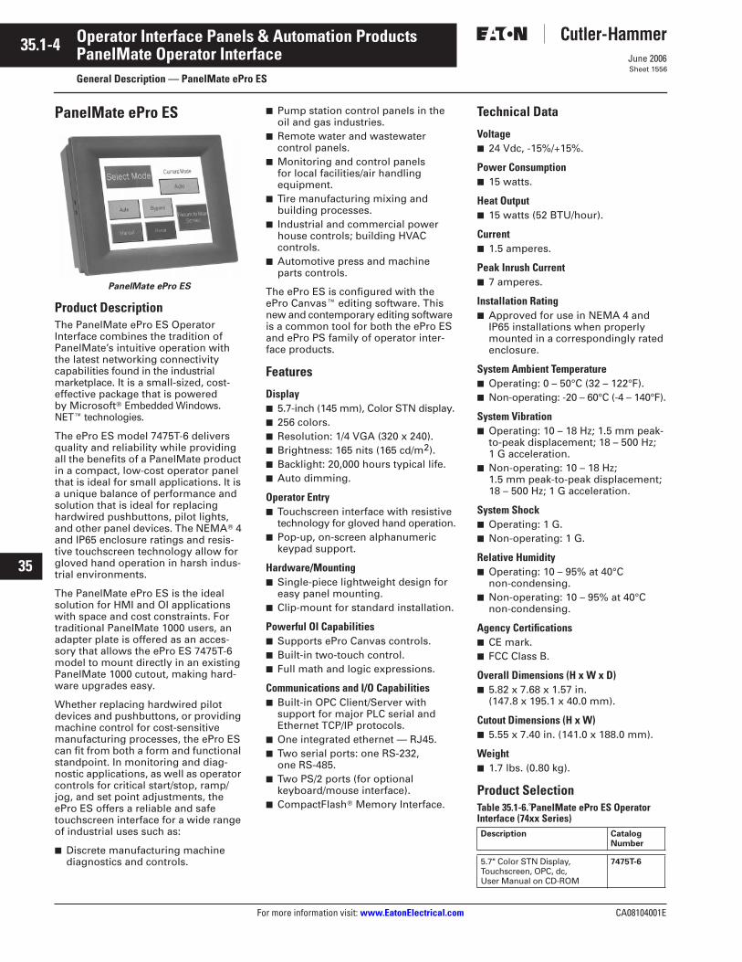
PanelMate ePro ES
Product Description
The PanelMate ePro ES Operator Interface combines the tradition of PanelMate’s intuitive operation with the latest networking connectivity capabilities found in the industrial marketplace. It is a small-sized, cost-effective package that is powered by Microsoft
T
Embedded Windows. NET
E
technologies.
The ePro ES model 7475T-6 delivers quality and reliability while providing all the benefits of a PanelMate product in a compact, low-cost operator panel that is ideal for small applications. It is a unique balance of performance and solution that is ideal for replacing hardwired pushbuttons, pilot lights, and other panel devices. The NEMA
T
4 and IP65 enclosure ratings and resis-tive touchscreen technology allow for gloved hand operation in harsh indus-trial environments.
The PanelMate ePro ES is the ideal solution for HMI and OI applications with space and cost constraints. For traditional PanelMate 1000 users, an adapter plate is offered as an acces-sory that allows the ePro ES 7475T-6 model to mount directly in an existing PanelMate 1000 cutout, making hard-ware upgrades easy.
Whether replacing hardwired pilot devices and pushbuttons, or providing machine control for cost-sensitive manufacturing processes, the ePro ES can fit from both a form and functional standpoint. In monitoring and diag-nostic applications, as well as operator controls for critical start/stop, ramp/jog, and set point adjustments, the ePro ES offers a reliable and safe touchscreen interface for a wide range of industrial uses such as:
■
Discrete manufacturing machine diagnostics and controls.
■
Pump station control panels in the oil and gas industries.
■
Remote water and wastewater control panels.
■
Monitoring and control panels for local facilities/air handling equipment.
■
Tire manufacturing mixing and building processes.
■
Industrial and commercial power house controls; building HVAC controls.
■
Automotive press and machine parts controls.
The ePro ES is configured with the ePro Canvas
E
editing software. This new and contemporary editing software is a common tool for both the ePro ES and ePro PS family of operator inter-face products.
Features
Display
■
5.7-inch (145 mm), Color STN display.
■
256 colors.
■
Resolution: 1/4 VGA (320 x 240).
■
Brightness: 165 nits (165 cd/m
2
).
■
Backlight: 20,000 hours typical life.
■
Auto dimming.
Operator Entry
■ Touchscreen interface with resistive technology for gloved hand operation.
■ Pop-up, on-screen alphanumeric keypad support.
Hardware/Mounting■ Single-piece lightweight design for
easy panel mounting.■ Clip-mount for standard installation.
Powerful OI Capabilities■ Supports ePro Canvas controls.■ Built-in two-touch control.■ Full math and logic expressions.
Communications and I/O Capabilities■ Built-in OPC Client/Server with
support for major PLC serial and Ethernet TCP/IP protocols.
■ One integrated ethernet — RJ45.■ Two serial ports: one RS-232,
one RS-485.■ Two PS/2 ports (for optional
keyboard/mouse interface).■ CompactFlashT Memory Interface.
Technical Data
Voltage■ 24 Vdc, -15%/+15%.
Power Consumption■ 15 watts.
Heat Output■ 15 watts (52 BTU/hour).
Current■ 1.5 amperes.
Peak Inrush Current■ 7 amperes.
Installation Rating■ Approved for use in NEMA 4 and
IP65 installations when properly mounted in a correspondingly rated enclosure.
System Ambient Temperature■ Operating: 0 – 50°C (32 – 122°F).■ Non-operating: -20 – 60°C (-4 – 140°F).
System Vibration■ Operating: 10 – 18 Hz; 1.5 mm peak-
to-peak displacement; 18 – 500 Hz; 1 G acceleration.
■ Non-operating: 10 – 18 Hz; 1.5 mm peak-to-peak displacement; 18 – 500 Hz; 1 G acceleration.
System Shock■ Operating: 1 G.■ Non-operating: 1 G.
Relative Humidity■ Operating: 10 – 95% at 40°C
non-condensing.■ Non-operating: 10 – 95% at 40°C
non-condensing.
Agency Certifications■ CE mark.■ FCC Class B.
Overall Dimensions (H x W x D)■ 5.82 x 7.68 x 1.57 in.
(147.8 x 195.1 x 40.0 mm).
Cutout Dimensions (H x W)■ 5.55 x 7.40 in. (141.0 x 188.0 mm).
Weight■ 1.7 lbs. (0.80 kg).
Product SelectionTable 35.1-6. PanelMate ePro ES Operator Interface (74xx Series)Description Catalog
Number
5.7" Color STN Display, Touchscreen, OPC, dc, User Manual on CD-ROM
7475T-6
CA08104001E For more information visit: www.EatonElectrical.com
35.1-5June 2006
Operator Interface Panels & Automation Products
22
23
24
25
26
27
28
29
30
31
32
33
34
35
36
37
38
39
40
41
42
43
PanelMate Operator InterfaceGeneral Description — PanelMate ePro PS
Sheet 1557
PanelMate ePro PS
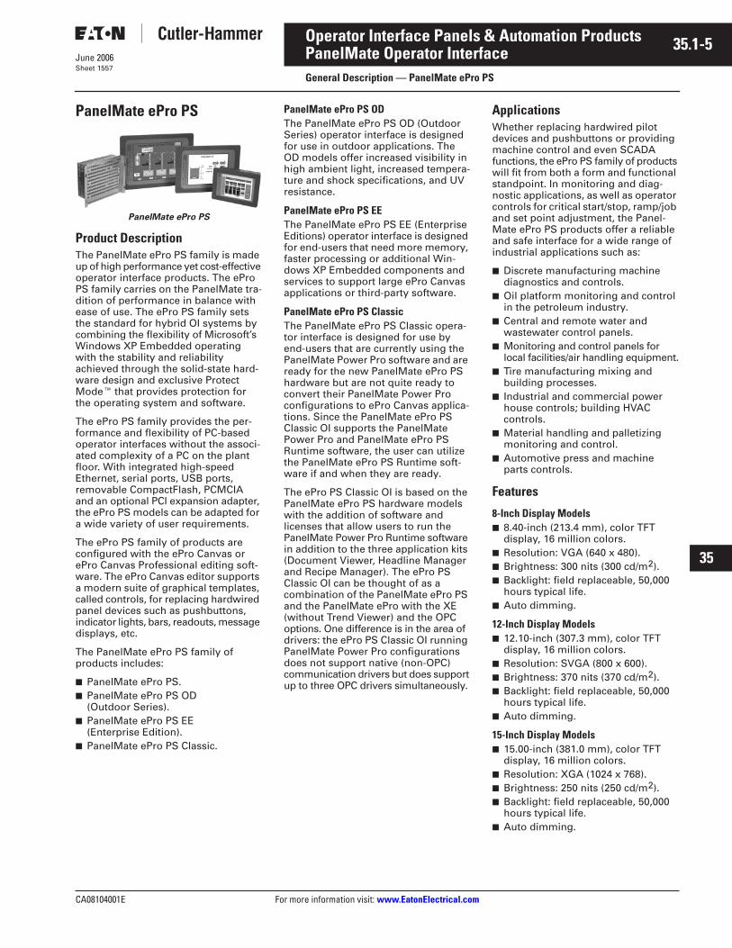
PanelMate ePro PS
Product DescriptionThe PanelMate ePro PS family is made up of high performance yet cost-effective operator interface products. The ePro PS family carries on the PanelMate tra-dition of performance in balance with ease of use. The ePro PS family sets the standard for hybrid OI systems by combining the flexibility of Microsoft’s Windows XP Embedded operating with the stability and reliability achieved through the solid-state hard-ware design and exclusive Protect ModeE that provides protection for the operating system and software.
The ePro PS family provides the per-formance and flexibility of PC-based operator interfaces without the associ-ated complexity of a PC on the plant floor. With integrated high-speed Ethernet, serial ports, USB ports, removable CompactFlash, PCMCIA and an optional PCI expansion adapter, the ePro PS models can be adapted for a wide variety of user requirements.
The ePro PS family of products are configured with the ePro Canvas or ePro Canvas Professional editing soft-ware. The ePro Canvas editor supports a modern suite of graphical templates, called controls, for replacing hardwired panel devices such as pushbuttons, indicator lights, bars, readouts, message displays, etc.
The PanelMate ePro PS family of products includes:
■ PanelMate ePro PS.■ PanelMate ePro PS OD
(Outdoor Series).■ PanelMate ePro PS EE
(Enterprise Edition).■ PanelMate ePro PS Classic.
PanelMate ePro PS ODThe PanelMate ePro PS OD (Outdoor Series) operator interface is designed for use in outdoor applications. The OD models offer increased visibility in high ambient light, increased tempera-ture and shock specifications, and UV resistance.
PanelMate ePro PS EEThe PanelMate ePro PS EE (Enterprise Editions) operator interface is designed for end-users that need more memory, faster processing or additional Win-dows XP Embedded components and services to support large ePro Canvas applications or third-party software.
PanelMate ePro PS ClassicThe PanelMate ePro PS Classic opera-tor interface is designed for use by end-users that are currently using the PanelMate Power Pro software and are ready for the new PanelMate ePro PS hardware but are not quite ready to convert their PanelMate Power Pro configurations to ePro Canvas applica-tions. Since the PanelMate ePro PS Classic OI supports the PanelMate Power Pro and PanelMate ePro PS Runtime software, the user can utilize the PanelMate ePro PS Runtime soft-ware if and when they are ready.
The ePro PS Classic OI is based on the PanelMate ePro PS hardware models with the addition of software and licenses that allow users to run the PanelMate Power Pro Runtime software in addition to the three application kits (Document Viewer, Headline Manager and Recipe Manager). The ePro PS Classic OI can be thought of as a combination of the PanelMate ePro PS and the PanelMate ePro with the XE (without Trend Viewer) and the OPC options. One difference is in the area of drivers: the ePro PS Classic OI running PanelMate Power Pro configurations does not support native (non-OPC) communication drivers but does support up to three OPC drivers simultaneously.
ApplicationsWhether replacing hardwired pilot devices and pushbuttons or providing machine control and even SCADA functions, the ePro PS family of products will fit from both a form and functional standpoint. In monitoring and diag-nostic applications, as well as operator controls for critical start/stop, ramp/job and set point adjustment, the Panel-Mate ePro PS products offer a reliable and safe interface for a wide range of industrial applications such as:
■ Discrete manufacturing machine diagnostics and controls.
■ Oil platform monitoring and control in the petroleum industry.
■ Central and remote water and wastewater control panels.
■ Monitoring and control panels for local facilities/air handling equipment.
■ Tire manufacturing mixing and building processes.
■ Industrial and commercial power house controls; building HVAC controls.
■ Material handling and palletizing monitoring and control.
■ Automotive press and machine parts controls.
Features
8-Inch Display Models■ 8.40-inch (213.4 mm), color TFT
display, 16 million colors.■ Resolution: VGA (640 x 480).■ Brightness: 300 nits (300 cd/m2).■ Backlight: field replaceable, 50,000
hours typical life.■ Auto dimming.
12-Inch Display Models■ 12.10-inch (307.3 mm), color TFT
display, 16 million colors.■ Resolution: SVGA (800 x 600).■ Brightness: 370 nits (370 cd/m2).■ Backlight: field replaceable, 50,000
hours typical life.■ Auto dimming.
15-Inch Display Models■ 15.00-inch (381.0 mm), color TFT
display, 16 million colors.■ Resolution: XGA (1024 x 768).■ Brightness: 250 nits (250 cd/m2).■ Backlight: field replaceable, 50,000
hours typical life.■ Auto dimming.
35.1-6
For more information visit: www.EatonElectrical.com CA08104001E
June 2006
Operator Interface Panels & Automation Products
22
23
24
25
26
27
28
29
30
31
32
33
34
35
36
37
38
39
40
41
42
43
PanelMate Operator InterfaceGeneral Description — PanelMate ePro PS
Sheet 1558
Blind Node (No Display) Models■ Resolution: SVGA (800 x 600), XGA
(1024 x 768), SXGA (1280 x 1024), UXGA (1600 x 1200).
■ Colors: 16 Million colors (SXGA and UXGA — 65K colors).
Operator Entry■ Touchscreen interface with resistive
technology for gloved hand operation.■ Pop-up, on-screen alphanumeric
keypad support.
Hardware/Mounting■ Single-piece design for easy panel
mounting (except 7600).
Powerful OI Capabilities■ Supports ePro Canvas controls.■ Built-in two-touch control.■ Full math and logic expressions.
Communications and I/O Capabilities■ One integrated Ethernet port —
10/100Base-T.■ Two serial ports: one RS-232, one
RS-232/422/485 optically isolated.■ Four USB ports (two V1.1, two V2.0).■ One CompactFlash memory card slot.■ Two PCMCIA Type II slots (or one
Type III).■ Support for optional PCI adapter
(12, 15-inch, Blind Node models).■ Built-in OPC Client/Server with sup-
port for over 50 OPC drivers for both Ethernet and serial connectivity.
■ One video output port.
Protect Mode■ This unique and exclusive feature
safeguards the integrity of operating system files and data files by pre-venting unauthorized alterations and corruption caused by viruses or unexpected power disruptions.
Technical Data
Voltage■ 24 Vdc.
Power Consumption■ 8-inch display models, 28 watts.■ 12-inch display models, 32 watts.■ 15-inch display models, 44 watts.■ Blind Node (no display) models,
20 watts.
Heat Output■ 8-inch display models, 28 watts
(96 BTU/hour).■ 12-inch display models, 32 watts
(109 BTU/hour).■ 15-inch display models, 44 watts
(150 BTU/hour).■ Blind Node (no display) models,
20 watts (68 BTU/hour).
Current■ 8-inch display models, 1.3 amperes.■ 12-inch display models, 1.5 amperes.■ 15-inch display models, 2.0 amperes.■ Blind Node (no display) models,
1.0 amperes.
Peak Inrush Current■ 8-inch display models, 7.0 amperes.■ 12-inch display models, 7.0 amperes.■ 15-inch display models, 8.0 amperes.■ Blind Node (no display) models,
7.0 amperes.
Installation Rating■ All ePro PS display models are
approved for use in Type 4, 4X, 12 and IP65 installations when properly mounted in a correspondingly rated enclosure.
System Ambient Temperature■ PS, EE and PS Classic models:
❑ Operating: 0 – 55°C (32 – 131°F), 0 – 50°C (32 – 122°F) with optional PCI adapter
❑ Non-operating: -25 – 70°C (-13 – 158°F)
■ OD models:❑ Operating: 0 – 60°C (32 – 140°F),
0 – 50°C (32 – 122°F) with optional PCI adapter
❑ Non-operating: -25 – 70°C (-13 – 158°F)
System Vibration■ Operating: 1 G from 5 – 500 Hz.■ Non-operating: 1 G from 5 – 500 Hz.
System Shock■ PS, EE and PS Classic models:
❑ Operating: 30 G❑ Non-operating: 30 G
■ OD models:❑ Operating: 100 G❑ Non-operating: 100 G
Relative Humidity■ Operating: 20 – 95% non-condensing.■ Non-operating: 20 – 95%
non-condensing.
Altitude■ Operating: 10,000 ft. (3,048 m)
above sea level.■ Non-operating: 40,000 ft. (12,192 m)
above sea level.
Emissions■ CISPR 22 Class A-Radiated and
Conducted.
Noise Immunity■ IEC 801-2, 3, 4, 6, 8.■ IEC 6100-4-2, 3, 4, 5, 6, 8.
Agency Certifications■ CE mark.■ UL/cUL and CSA Class I, Div 2,
Groups A, B, C, D.
Overall Dimensions (H x W x D)■ 8-inch display models — 7.63 x
10.51 x 3.90 in. (193.8 x 267.0 x 99.1 mm).
■ 12-inch display models — 11.60 x 15.90 x 3.90 in. (294.6 x 403.9 x 99.1 mm).
■ 15-inch display models — 13.50 x 18.60 x 5.00 in. (342.9 x 472.4 x 127.0 mm).
■ Blind Node (no display) models — 9.30 x 12.00 x 4.90 in. (236.2 x 304.8 x 124.0 mm).
Note: Add 1.30 in. (33.0 mm) to depth for optional PCI adapter.
Cutout Dimensions (H x W)■ 8-inch display models — 6.50 x
9.38 in. (165.1 x 238.3 mm).■ 12-inch display models — 10.12 x
14.34 in. (257.0 x 364.2 mm).■ 15-inch display models — 12.05 x
17.01 in. (306.1 x 432.1 mm).■ Blind Node (no display) models
designed for mounting in a cabinet.
Weight■ 8-inch display models — 7.0 lbs.
(3.18 kg).■ 12-inch display models — 14.0 lbs.
(6.35 kg).■ 15-inch display models — 18.0 lbs.
(8.16 kg).■ Blind Node (no display) models —
5.0 lbs. (2.27 kg).

CA08104001E For more information visit: www.EatonElectrical.com
35.1-7June 2006
Operator Interface Panels & Automation Products
22
23
24
25
26
27
28
29
30
31
32
33
34
35
36
37
38
39
40
41
42
43
PanelMate Operator InterfaceGeneral Description — PanelMate ePro PS
Sheet 1559
Product SelectionTable 35.1-7. PanelMate ePro Operator InterfaceDescription Catalog
Number
PanelMate ePro PS Operator Interface8.4" Color TFT Display, Touchscreen (Acrylic), OPC, dc, User Manual on CD-ROM 7685T-8
12.1" Color TFT Display, Touchscreen (Glass), OPC, Painted Steel, dc, User Manual on CD-ROM
7685T-12
12.1" Color TFT Display, Touchscreen (Glass), OPC, Stainless Steel, dc, User Manual on CD-ROM
7685ST-12
15.0" Color TFT Display, Touchscreen (Glass), OPC, Painted Steel, dc, User Manual on CD-ROM
7685T-15
15.0" Color TFT Display, Touchscreen (Glass), OPC, Stainless Steel, dc, User Manual on CD-ROM
7685ST-15
Blind Node (No Display – see Table 35.1-8 for Display Options), OPC, dc, User Manual on CD-ROM
7600
PanelMate ePro PS EE Operator Interface12.1" Color TFT Display, Touchscreen (Glass), OPC, Painted Steel, dc, User Manual on CD-ROM
7685T-12E
15.0" Color TFT Display, Touchscreen (Glass), OPC, Painted Steel, dc,User Manual on CD-ROM
7685T-15E
Blind Node (No Display – see Flat Panel Displays for Display Options), OPC, dc, User Manual on CD-ROM
7600E
PanelMate ePro PS OD Operator Interface12.1" Color TFT Display, Touchscreen (Glass), OPC, Painted Steel, dc, User Manual on CD-ROM
7685T-12OD
12.1" Color TFT Display, Touchscreen (Glass), OPC, Stainless Steel, dc, User Manual on CD-ROM
7685ST-12OD
PanelMate ePro PS Classic Operator Interface8.4" Color TFT Display, Touchscreen (Acrylic), OPC, dc, User Manual on CD-ROM 7685T-8C
Blind Node (No Display – see Table 35.1-9 for Display Options), OPC, dc, User Manual on CD-ROM
7600C
35.1-8
For more information visit: www.EatonElectrical.com CA08104001E
June 2006
Operator Interface Panels & Automation Products
22
23
24
25
26
27
28
29
30
31
32
33
34
35
36
37
38
39
40
41
42
43
PanelMate Operator InterfaceGeneral Description — PanelMate Flat Panel Displays
Sheet 1560
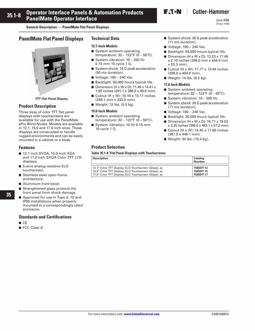
PanelMate Flat Panel Displays
TFT Flat Panel Display
Product DescriptionThree sizes of color TFT flat panel displays with touchscreens are available for use with the PanelMate ePro Blind Nodes. Models are available in 12.1, 15.0 and 17.0-inch sizes. These displays are constructed to handle rugged environments and can be easily mounted in a cabinet or a kiosk.
Features■ 12.1-inch SVGA, 15.0-inch XGA
and 17.0-inch SXGA Color TFT LCD displays.
■ 5-wire analog resistive ELO touchscreen.
■ Stainless steel open-frame architecture.
■ Aluminum front bezel.■ Strengthened glass protects the
front panel from shock damage.■ Approved for use in Type 4, 12 and
IP65 installations when properly mounted in a correspondingly rated enclosure.
Standards and Certifications■ CE■ FCC Class A
Technical Data
12.1-Inch Models■ System ambient operating
temperature: 32 – 122°F (0 – 50°C).■ System vibration: 10 – 200 Hz
0.15 mm 10 cycle 1 G.■ System shock: 15 G peak acceleration
(50 ms duration).■ Voltage: 100 – 240 Vac.■ Backlight: 50,000 hours typical life.■ Dimension (H x W x D): 11.46 x 14.41 x
1.92 inches (291.1 x 366.0 x 48.8 mm).■ Cutout (H x W): 10.16 x 13.11 inches
(258.1 mm x 333.0 mm).■ Weight: 12 lbs. (5.5 kg).
15.0-Inch Models■ System ambient operating
temperature: 32 – 122°F (0 – 50°C).■ System vibration: 10 Hz 0.15 mm
10 cycle 1 G.
■ System shock: 30 G peak acceleration (11 ms duration).
■ Voltage: 100 – 240 Vac.■ Backlight: 50,000 hours typical life.■ Dimension (H x W x D): 13.23 x 17.48
x 2.10 inches (336.0 mm x 444.0 mm x 53.3 mm).
■ Cutout (H x W): 11.77 x 15.94 inches(299.0 x 404.9 mm).
■ Weight: 14 lbs. (6.5 kg).
17.0-Inch Models■ System ambient operating
temperature: 32 – 122°F (0 – 50°C).■ System vibration: 10 – 500 Hz.■ System shock: 30 G peak acceleration
(11 ms duration).■ Voltage: 100 – 240 Vac.■ Backlight: 30,000 hours typical life.■ Dimension (H x W x D): 15.71 x 19.02
x 2.25 inches (399.0 x 483.1 x 57.2 mm).■ Cutout (H x W): 14.45 x 17.68 inches
(367.0 x 449.1 mm).■ Weight: 34 lbs. (15.4 kg).
Product SelectionTable 35.1-8. Flat Panel Displays with Touchscreens Description Catalog
Number
12.1" Color TFT Display, ELO Touchscreen (Glass), ac15.0" Color TFT Display, ELO Touchscreen (Glass), ac17.0" Color TFT Display, ELO Touchscreen (Glass), ac
7585DT-127585DT-157585DT-17
CA08104001E For more information visit:
www.EatonElectrical.com
35.1-9
June 2006
Operator Interface Panels & Automation Products
22
23
24
25
26
27
28
29
30
31
32
33
34
35
36
37
38
39
40
41
42
43
PanelMate Operator Interface
General Description — PanelMate PC Pro Software
Sheet 1561
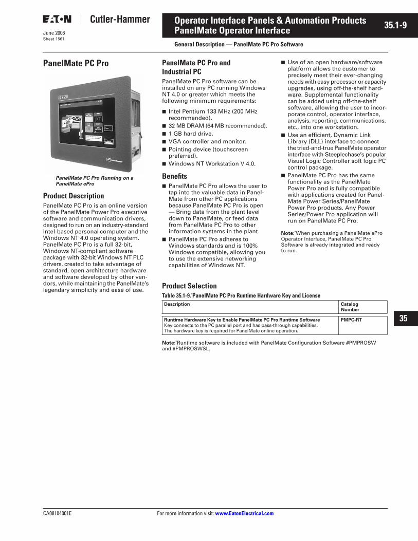
PanelMate PC Pro
PanelMate PC Pro Running on a PanelMate ePro
Product Description
PanelMate PC Pro is an online version of the PanelMate Power Pro executive software and communication drivers, designed to run on an industry-standard Intel-based personal computer and the Windows NT 4.0 operating system. PanelMate PC Pro is a full 32-bit, Windows NT-compliant software package with 32-bit Windows NT PLC drivers, created to take advantage of standard, open architecture hardware and software developed by other ven-dors, while maintaining the PanelMate’s legendary simplicity and ease of use.
PanelMate PC Pro and Industrial PC
PanelMate PC Pro software can be installed on any PC running Windows NT 4.0 or greater which meets the following minimum requirements:
■
Intel Pentium 133 MHz (200 MHz recommended).
■
32 MB DRAM (64 MB recommended).
■
1 GB hard drive.
■
VGA controller and monitor.
■
Pointing device (touchscreen preferred).
■
Windows NT Workstation V 4.0.
Benefits
■
PanelMate PC Pro allows the user to tap into the valuable data in Panel-Mate from other PC applications because PanelMate PC Pro is open — Bring data from the plant level down to PanelMate, or feed data from PanelMate PC Pro to other information systems in the plant.
■
PanelMate PC Pro adheres to Windows standards and is 100% Windows compatible, allowing you to use the extensive networking capabilities of Windows NT.
■
Use of an open hardware/software platform allows the customer to precisely meet their ever-changing needs with easy processor or capacity upgrades, using off-the-shelf hard-ware. Supplemental functionality can be added using off-the-shelf software, allowing the user to incor-porate control, operator interface, analysis, reporting, communications, etc., into one workstation.
■
Use an efficient, Dynamic Link Library (DLL) interface to connect the tried-and-true PanelMate operator interface with Steeplechase’s popular Visual Logic Controller soft logic PC control package.
■
PanelMate PC Pro has the same functionality as the PanelMate Power Pro and is fully compatible with applications created for Panel-Mate Power Series/PanelMate Power Pro products. Any Power Series/Power Pro application will run on PanelMate PC Pro.
Note:
When purchasing a PanelMate ePro Operator Interface, PanelMate PC Pro Software is already integrated and ready to run.
Product Selection
Table 35.1-9. PanelMate PC Pro Runtime Hardware Key and License
Note:
Runtime software is included with PanelMate Configuration Software #PMPROSW and #PMPROSWSL.
Description CatalogNumber
Runtime Hardware Key to Enable PanelMate PC Pro Runtime Software
Key connects to the PC parallel port and has pass-through capabilities. The hardware key is required for PanelMate online operation.
PMPC-RT

35.1-10
For more information visit: www.EatonElectrical.com CA08104001E
June 2006
Operator Interface Panels & Automation Products
22
23
24
25
26
27
28
29
30
31
32
33
34
35
36
37
38
39
40
41
42
43
Sheet 1562
This page intentionally left blank.
CA08104001E For more information visit:
www.EatonElectrical.com
35.2-1
June 2006
Operator Interface Panels & Automation Products
22
23
24
25
26
27
28
29
30
31
32
33
34
35
36
37
38
39
40
41
42
43
PanelMate Software
General Description — PanelMate Configuration Software
Sheet 1563
PanelMate Power Pro, PanelMate PC Pro and PanelMate ePro Configuration Software
Application Description
Windows-based configuration software is used to create PanelMate Power Pro, PanelMate PC Pro and PanelMate ePro configurations offline on a PC. It also permits the editing of character-based configurations from earlier-version PanelMate Series products. The following items can be configured:
■
One-touch control (for touchscreen models).
■
Customizable pixel-level graphics.
■
8-state blink (for 256-level/color models).
■
3-level password protection.
■
International character set support.
■
Page change by operators and/or PLC.
■
User-definable online system prompts to permit non-English or customized text that can be toggled with standard online prompts by operators.
■
Alarm window with a 100-alarm capacity.
Features
■
Indicator templates.
■
Readout templates.
■
Bar templates.
■
Display templates.
■
Trend templates.
■
Table templates.
■
Variable-size control button templates.
■
Pop-up maintenance window.
■
Alarm window.
■
Advanced trend templates.
■
Tag name file support.
■
Expression management.
■
3000 symbol factory clipart.
PLC Communication Interfaces
Communication interfaces are avail-able for the following programmable controllers and are downloaded from the configuration software.
Note:
Multiple interfaces may be run simultaneously on PanelMate Power Pro 1700, 2000, 3000, 4000 and 5000 units.
■
Allen-Bradley PLC-2, PLC-3, PLC-5 and SLC-500.
■
Cutler-Hammer D50, D300, D320.
■
GE
T
Fanuc
T
Series 5, 6, 90.
■
Mitsubishi
T
“A” Series and “FX” Series.
■
Modicon
T
Modbus
T
ASCII/RTU.
■
Omron “C” Series plus CV500, CV1000.
■
PLC-Direct DL 405 Family.
■
Square D
T
SyMax.
■
Siemens
T
S5 Series, 3964R Protocol, AS511.
■
Simatic
T
TI 305/405 and 500/505 Series.
■
Reliance AutoMate
T
.
■
Toshiba T2.
High Speed Direct Connectivity Available
■
Allen-Bradley Data Highway and Data Highway Plus.
■
Allen-Bradley Remote I/O Link.
■
GE Fanuc GEnius
T
I/O Network.
■
DeviceNet
E
.
■
Modicon Modbus Plus.
■
PROFIBUS
T
.
Transfer Cables
PanelMate configuration software pack-ages #PMPROSW and #PMPROSWSL include a PanelMate 1100, 1700, 3000, 5000 (#0518) Transfer Serial Cable.
Product Selection
Table 35.2-1. Windows Configuration Software for PanelMate Power Pro, PanelMate PC Pro and PanelMate ePro
Automation Update Service Membership
All purchases of PanelMate Power Pro software qualify you for product announce-ments and free service releases from the Automation Update Service when you register using the forms included in the software packages.
Description CatalogNumber
PanelMate Power Pro Windows Configuration Software and Manuals with Com-munication Software Interfaces for all major PLCs and High Speed Industrial Networks on CD-ROM with Tag and ExpressionManagement and Symbol Factory Clipart.
#PMPROSW includes transfer serial cable for PM1700, 3000, 5000 (#0518). #PMPROSW includes electronic copies of manuals in .PDF format.Seat license (1 user).
PMPROSW
Site License — See PMPROSW (for all users at 1 site location) PMPROSWSL
PanelMate Power Pro Upgrade from previous PanelMate Power Series Software
to PanelMate Power Pro software version on CD-ROM. Requires earlier version of PanelMate Power Series software for installation.
PMPROSWUP
PanelMate Power Pro Software Upgrade — Site License
Requires previous installation of PanelMate Power Pro Software Site License (PMPROSWSL). On CD-ROM.
PMPROSWSLUP
35.2-2
For more information visit:
www.EatonElectrical.com
CA08104001E
June 2006
Operator Interface Panels & Automation Products
22
23
24
25
26
27
28
29
30
31
32
33
34
35
36
37
38
39
40
41
42
43
PanelMate Software
General Description — ePro Software Suite
Sheet 1564
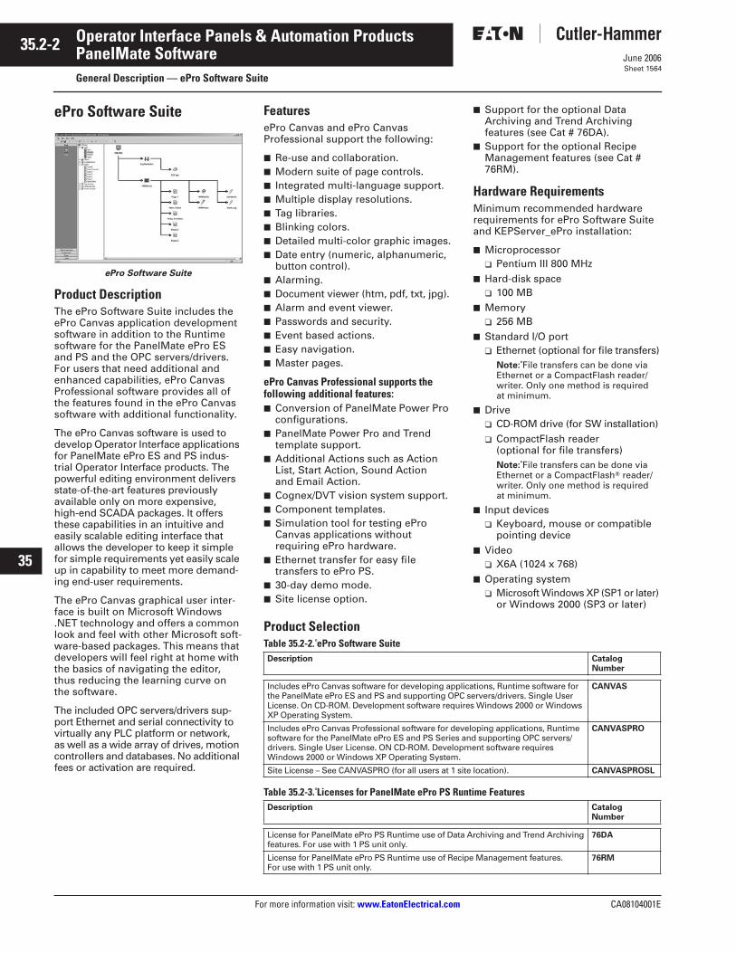
ePro Software Suite
ePro Software Suite
Product Description
The ePro Software Suite includes the ePro Canvas application development software in addition to the Runtime software for the PanelMate ePro ES and PS and the OPC servers/drivers. For users that need additional and enhanced capabilities, ePro Canvas Professional software provides all of the features found in the ePro Canvas software with additional functionality.
The ePro Canvas software is used to develop Operator Interface applications for PanelMate ePro ES and PS indus-trial Operator Interface products. The powerful editing environment delivers state-of-the-art features previously available only on more expensive, high-end SCADA packages. It offers these capabilities in an intuitive and easily scalable editing interface that allows the developer to keep it simple for simple requirements yet easily scale up in capability to meet more demand-ing end-user requirements.
The ePro Canvas graphical user inter-face is built on Microsoft Windows .NET technology and offers a common look and feel with other Microsoft soft-ware-based packages. This means that developers will feel right at home with the basics of navigating the editor, thus reducing the learning curve on the software.
The included OPC servers/drivers sup-port Ethernet and serial connectivity to virtually any PLC platform or network, as well as a wide array of drives, motion controllers and databases. No additional fees or activation are required.
Features
ePro Canvas and ePro Canvas Professional support the following:
■
Re-use and collaboration.
■
Modern suite of page controls.
■
Integrated multi-language support.
■
Multiple display resolutions.
■
Tag libraries.
■
Blinking colors.
■
Detailed multi-color graphic images.
■
Date entry (numeric, alphanumeric, button control).
■
Alarming.
■
Document viewer (htm, pdf, txt, jpg).
■
Alarm and event viewer.
■
Passwords and security.
■
Event based actions.
■
Easy navigation.
■
Master pages.
ePro Canvas Professional supports the following additional features:
■
Conversion of PanelMate Power Pro configurations.
■
PanelMate Power Pro and Trend template support.
■
Additional Actions such as Action List, Start Action, Sound Action and Email Action.
■
Cognex/DVT vision system support.
■
Component templates.
■
Simulation tool for testing ePro Canvas applications without requiring ePro hardware.
■
Ethernet transfer for easy file transfers to ePro PS.
■
30-day demo mode.
■
Site license option.
■
Support for the optional Data Archiving and Trend Archiving features (see Cat # 76DA).
■
Support for the optional Recipe Management features (see Cat # 76RM).
Hardware Requirements
Minimum recommended hardware requirements for ePro Software Suite and KEPServer_ePro installation:
■
Microprocessor
❑
Pentium III 800 MHz
■
Hard-disk space
❑
100 MB
■
Memory
❑
256 MB
■
Standard I/O port
❑
Ethernet (optional for file transfers)
Note:
File transfers can be done via Ethernet or a CompactFlash reader/writer. Only one method is required at minimum.
■
Drive
❑
CD-ROM drive (for SW installation)
❑
CompactFlash reader (optional for file transfers)
Note:
File transfers can be done via Ethernet or a CompactFlash
T
reader/writer. Only one method is required at minimum.
■
Input devices
❑
Keyboard, mouse or compatible pointing device
■
Video
❑
X6A (1024 x 768)
■
Operating system
❑
Microsoft Windows XP (SP1 or later)
or Windows 2000 (SP3 or later)
Product Selection
Table 35.2-2. ePro Software Suite
Table 35.2-3. Licenses for PanelMate ePro PS Runtime Features
Description CatalogNumber
Includes ePro Canvas software for developing applications, Runtime software for the PanelMate ePro ES and PS and supporting OPC servers/drivers. Single User License. On CD-ROM. Development software requires Windows 2000 or Windows XP Operating System.
CANVAS
Includes ePro Canvas Professional software for developing applications, Runtime software for the PanelMate ePro ES and PS Series and supporting OPC servers/drivers. Single User License. ON CD-ROM. Development software requires Windows 2000 or Windows XP Operating System.
CANVASPRO
Site License – See CANVASPRO (for all users at 1 site location).
CANVASPROSL
Description CatalogNumber
License for PanelMate ePro PS Runtime use of Data Archiving and Trend Archiving features. For use with 1 PS unit only.
76DA
License for PanelMate ePro PS Runtime use of Recipe Management features. For use with 1 PS unit only.
76RM
CA08104001E For more information visit:
www.EatonElectrical.com
35.2-3
June 2006
Operator Interface Panels & Automation Products
22
23
24
25
26
27
28
29
30
31
32
33
34
35
36
37
38
39
40
41
42
43
PanelMate Software
General Description — PanelMate Communications
Sheet 1565
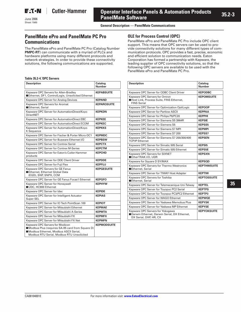
PanelMate ePro and PanelMate PC Pro Communications
The PanelMate ePro and PanelMate PC Pro (Catalog Number
PMPC-RT
) can communicate with a myriad of PLCs and hardware platforms using many different protocols and network strategies. In order to provide these connectivity solutions, the following communications are supported.
OLE for Process Control (OPC)PanelMate ePro and PanelMate PC Pro include OPC client support. This means that OPC servers can be used to pro-vide connectivity solutions for many different types of com-munication protocols. OPC provides a fast, precise, economic and efficient solution to communication needs. EatonCorporation has formed a partnership with Kepware, the leading supplier of OPC connectivity solutions, so that the following OPC servers are available to be used with the PanelMate ePro and PanelMate PC Pro.
Table 35.2-4. OPC Servers Description Catalog
Number
Kepware OPC Servers for Allen-Bradley■ Ethernet, DF1, ControlLogix, Unsolicited Ethernet
KEPABSUITE
Kepware OPC Server for Analog Devices KEPAND
Kepware OPC Servers for Aromat■ Ethernet, Serial
KEPAROSUITE
Kepware OPC Server for AutomationDirect/Koyo DirectNET
KEPKDN
Kepware OPC Server for AutomationDirect EBC KEPKEE
Kepware OPC Server for AutomationDirect ECOM KEPKEC
Kepware OPC Server for AutomationDirect/Koyo K Sequence
KEPKKS
Kepware OPC Server for Fischer & Porter Micro-DC1 KEPMDC
Kepware OPC Server for Busware Ethernet I/O KEPBSW
Kepware OPC Server for Contrex Serial KEPCTX
Kepware OPC Server for Contrex M-Series KEPCTM
Kepware OPC Server for Eaton’s Cutler-Hammer products
KEPCHD
Kepware OPC Server for DDE Client Driver KEPDDE
Kepware OPC Server for Fuji Flex KEPFUJ
Kepware OPC Servers for GE Fanuc■ Ethernet, Ethernet Global Data
(EGD), SNP, SNPX, CCM
KEPGESUITE
Kepware OPC Server for GE Fanuc Focas1 Ethernet KEPGFO
Kepware OPC Server for Honeywell■ UDC, HC900 Ethernet
KEPHYW
Kepware OPC Server for Idec KEPIDE
Kepware OPC Server for Intelligent Actuator Super SEL
KEPIAS
Kepware OPC Server for IO Tech PointScan 100 KEPIOT
Kepware OPC Server for Mitsubishi Ethernet KEPMAE
Kepware OPC Server for Mitsubishi A-Series KEPMTA
Kepware OPC Server for Mitsubishi FX KEPMFX
Kepware OPC Server for Mitsubishi FX Net KEPMFN
Kepware OPC Servers for Modicon■ Modbus Plus (requires SA-85 card from Square D)■ Modbus Ethernet, Modbus ASCII Serial,
Modbus RTU Serial, Modbus RTU Unsolicited
KEPMODSUITE
Description CatalogNumber
Kepware OPC Server for ODBC Client Driver KEPODBC
Kepware OPC Servers for Omron■ Host Link, Process Suite, FINS Ethernet,
FINS Serial
KEPOMSUITE
Kepware OPC Server for Optimization OptiLogic KEPOOP
Kepware OPC Server for Partlow ASCII KEPPAA
Kepware OPC Server for Philips P8/PC20 KEPPHI
Kepware OPC Server for Siemens S5 3964R KEPSIE
Kepware OPC Server for Siemens S5 KEPSS5
Kepware OPC Server for Siemens S7 MPI KEPMPI
Kepware OPC Server for Siemens S7 200 KEPSS7
Kepware OPC Server for Siemens S7 200/300/400 TCP/IP Ethernet
KEPSEN
Kepware OPC Server for Simatic 505 Serial KEPSI5
Kepware OPC Server for Simatic 505 Ethernet KEPS5E
Kepware OPC Servers for SIXNET■ EtherTRAK I/O, UDR
KEPSXN
Kepware for Square D SY/MAX KEPSQD
Kepware OPC Servers for Thermo Westronics■ Ethernet, Serial
KEPTHWSUITE
Kepware OPC Server for TIWAY Host Adapter KEPTIW
Kepware OPC Servers for Toshiba■ Ethernet, Serial
KEPTOSSUITE
Kepware OPC Server for Telemecanique Uni-Telway KEPTEL
Kepware OPC Server for Toyopuc PC2 Serial KEPTPS
Kepware OPC Server for Toyopuc PC3/PC2 Ethernet KEPTP3
Kepware OPC Server for WAGO Ethernet KEPWGE
Kepware OPC Server for Yaskawa Memobus Plus KEPYSK
Kepware OPC Server for Yaskawa MP Ethernet KEPYSE
Kepware OPC Servers for Yokogawa■ Darwin Ethernet, Darwin Serial, DX Ethernet,
DX Serial, DXP, HR, CX
KEPYOKSUITE
35.2-4
For more information visit: www.EatonElectrical.com CA08104001E
June 2006
Operator Interface Panels & Automation Products
22
23
24
25
26
27
28
29
30
31
32
33
34
35
36
37
38
39
40
41
42
43
PanelMate SoftwareGeneral Description — PanelMate Communications
Sheet 1566
Also, by using the OPC client/server strategy and special hardware, the PanelMate ePro and PanelMate PC Pro can connect to a variety of high-speed networks. Authorized con-nectivity solutions are available from SST and Square D.
■ SST ControlNet Interface Card and OPC Server —5136-CN ISA.
■ SST PROFIBUS DP Interface Card and OPC Server —5136-PBMS ISA.
■ Square D Modbus Plus SA-85 Interface Card — SA-85-300 ISA (OPC server purchased separately — see KEPMBP OPC server in Table 35.2-4).
Note: For communications using Allen-Bradley’s Data Highway Plus protocol, customers can purchase an ISA interface board from Eaton (Cutler-Hammer Catalog Number D712-DHP-ISA). The communication driver used with the board is provided with the PanelMate Configuration Software.
Dynamic Data Exchange (DDE)Using the Microsoft standard DDE interface, PanelMate PC Pro data can be easily and efficiently shared with any other applications that support DDE, such as Microsoft ExcelT, Microsoft AccessT, Visual BasicT and Visual C++. PanelMate PC Pro’s built-in DDE connectivity provides simple integra-tion with other applications for report generation, recipe management, machine setup, data analysis and archiving.
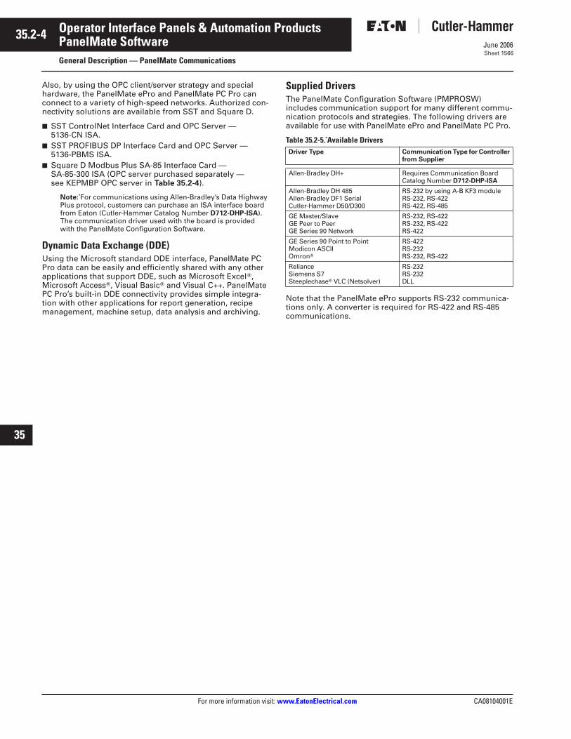
Supplied DriversThe PanelMate Configuration Software (PMPROSW) includes communication support for many different commu-nication protocols and strategies. The following drivers are available for use with PanelMate ePro and PanelMate PC Pro.
Table 35.2-5. Available Drivers
Note that the PanelMate ePro supports RS-232 communica-tions only. A converter is required for RS-422 and RS-485 communications.
Driver Type Communication Type for Controller from Supplier
Allen-Bradley DH+ Requires Communication Board Catalog Number D712-DHP-ISA
Allen-Bradley DH 485Allen-Bradley DF1 SerialCutler-Hammer D50/D300
RS-232 by using A-B KF3 moduleRS-232, RS-422RS-422, RS-485
GE Master/SlaveGE Peer to PeerGE Series 90 Network
RS-232, RS-422RS-232, RS-422RS-422
GE Series 90 Point to PointModicon ASCIIOmronT
RS-422RS-232RS-232, RS-422
RelianceSiemens S7SteeplechaseT VLC (Netsolver)
RS-232RS-232DLL
CA08104001E For more information visit:
www.EatonElectrical.com
35.3-1
June 2006
Operator Interface Panels & Automation Products
22
23
24
25
26
27
28
29
30
31
32
33
34
35
36
37
38
39
40
41
42
43
Connectivity: Utilities, Interfaces & Cables
PanelMate — Communication Utilities and Connectivity
Sheet 1567
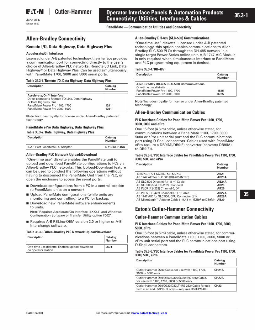
Allen-Bradley Connectivity
Remote I/O, Data Highway, Data Highway Plus
Accelerate/On Interface
Licensed under A-B patented technology, the interface provides
a communication port for connecting directly to the user’s choice of Allen-Bradley PLC networks: Remote I/O Link, Data Highway
T
or Data Highway Plus. Can be used simultaneously with PanelMate 1700, 3000 and 5000 serial ports.
Table 35.3-1. Remote I/O, Data Highway, Data Highway Plus
Note:
Includes royalty for license under Allen-Bradley patented technology.
PanelMate ePro Data Highway, Data Highway PlusTable 35.3-2. Data Highway, Data Highway Plus
Allen-Bradley PLC Network Upload/Download
“One-time use” diskette enables the PanelMate unit to upload and download PanelMate configurations to PCs via Allen-Bradley PLC networks. This Upload/Download feature can be used to conduct the following operations without having to disconnect the PanelMate Unit from the PLC, or open the enclosure to access the serial ports:
■
Download configurations from a PC in a central location to PanelMate units on a network.
■
Upload PanelMate configurations (while units are monitoring and controlling) to a PC for backup.
■
Download new PanelMate software enhancements to units.
Note:
Requires Accelerate/On Interface (#XX41) and WindowsConfiguration Software or Transfer Utility option #0621.
■
Requires A-B RSLinx-OEM version 2.0 or higher or A-B Interchange software.
Table 35.3-3. Allen-Bradley PLC Network Upload/Download
Allen-Bradley DH-485 (SLC-500) Communications
“One-time use” diskette. Licensed under A-B patented technology, this option enables communications to Allen-Bradley SLC-500 PLCs through the DH-485 network in a single target Power Series online unit. A-B 1747-AIC Module is only required when simultaneous interface to PanelMate and PLC programming equipment is desired.
Table 35.3-4. DH-485
Note:
Includes royalty for license under Allen-Bradley patented technology.
Allen-Bradley Communication Cables
PLC Interface Cables for PanelMate Power Pro 1100, 1700, 3000, 5000 and ePro
One 15-foot (4.6 m) cable, unless otherwise stated, for communications between a PanelMate 1100, 1700, 3000, 5000 or ePro unit serial port and the PLC communications port using D-Shell connectors. Cables used with PanelMate ePro require a DB9(M)/DB9(F) converter (converts DB9(M) to DB9(F)).
Table 35.3-5. PLC Interface Cables for PanelMate Power Pro 1100, 1700, 3000, 5000 and ePro
Eaton’s Cutler-Hammer Connectivity
Cutler-Hammer Communication Cables
PLC Interface Cables for PanelMate Power Pro 1100, 1700, 3000, 5000, ePro
One 15-foot (4.6 m) cable, unless otherwise stated, for commu-nications between a PanelMate 1100, 1700, 3000, 5000 or ePro unit serial port and the PLC communications port using D-Shell connectors.
Table 35.3-6. PLC Interface Cables for PanelMate Power Pro 1100, 1700, 3000, 5000, ePro
Description CatalogNumber
Accelerate/On™ Interface
Direct connect to Remote I/O Link, Data Highway or Data Highway PlusPanelMate Power Pro 1100, 1700PanelMate Power Pro 3000, 5000
12411251
Description CatalogNumber
ISA 1 Port PanelMate PC Adapter
D712-DHP-ISA
Description CatalogNumber
One-time use diskette. Enables upload/download on operator station.
0524
Description CatalogNumber
Allen-Bradley DH-485 (SLC-500) Communications
One-time use diskettePanelMate Power Pro 1100, 1700PanelMate Power Pro 3000, 5000
15250725
Description CatalogNumber
1785-KE, 1771-KC, KD, KE, KF, KGAB 1747 AIC for SLC 500 (DH-485 INTFC)
AB21AB23A
AB SLC 500 Direct (6 ft./1.8 m) CableAB SLC503/504 (RS-232) Channel 0AB PLC5 (RS-232) Channel 0, DF1
AB24AAB25AB26
AB PLC5 (RS-422) Channel 0, DF1 CableAB 1747 AIC for SLC 500, CPU Connector (J1) AB MicroLogix
E
Adapter Cable (1 ft./.3 m) (DB9F to DB9M)
AB27AAB28AAB29
Description CatalogNumber
Cutler-Hammer D200 Cable, for use with 1100, 1700, 3000 or 5000 only
CH21A
Cutler-Hammer D50/D150/D300/D320 (RS-485) Cable, for use with 1100, 1700, 3000 or 5000 only
CH22A
Cutler-Hammer D50/D320/D32LT (RS-232) Cable for use with ePro and PMPC-RT only — requires D50CPM485
CH23
35.3-2
For more information visit:
www.EatonElectrical.com
CA08104001E
June 2006
Operator Interface Panels & Automation Products
22
23
24
25
26
27
28
29
30
31
32
33
34
35
36
37
38
39
40
41
42
43
Connectivity: Utilities, Interfaces & Cables
PanelMate — Communication Utilities and Connectivity
Sheet 1568
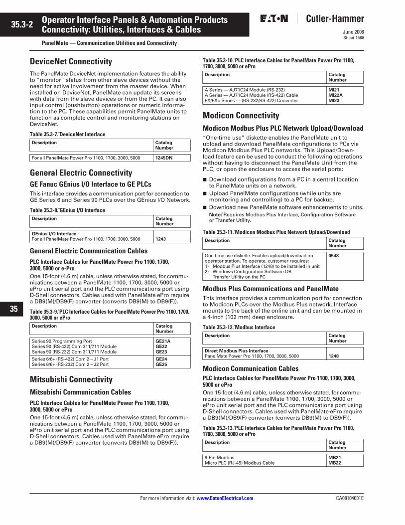
DeviceNet Connectivity
The PanelMate DeviceNet implementation features the ability to “monitor” status from other slave devices without the need for active involvement from the master device. When installed on DeviceNet, PanelMate can update its screens with data from the slave devices or from the PC. It can also input control (pushbutton) operations or numeric informa-tion to the PC. These capabilities permit PanelMate units to function as complete control and monitoring stations on DeviceNet.
Table 35.3-7. DeviceNet Interface
General Electric Connectivity
GE Fanuc GEnius I/O Interface to GE PLCs
This interface provides a communication port for connection to GE Series 6 and Series 90 PLCs over the GEnius I/O Network.
Table 35.3-8. GEnius I/O Interface
General Electric Communication Cables
PLC Interface Cables for PanelMate Power Pro 1100, 1700, 3000, 5000 or e-Pro
One 15-foot (4.6 m) cable, unless otherwise stated, for commu-nications between a PanelMate 1100, 1700, 3000, 5000 or ePro unit serial port and the PLC communications port using D-Shell connectors. Cables used with PanelMate ePro require a DB9(M)/DB9(F) converter (converts DB9(M) to DB9(F)).
Table 35.3-9. PLC Interface Cables for PanelMate Power Pro 1100, 1700, 3000, 5000 or ePro
Mitsubishi Connectivity
Mitsubishi Communication Cables
PLC Interface Cables for PanelMate Power Pro 1100, 1700, 3000, 5000 or ePro
One 15-foot (4.6 m) cable, unless otherwise stated, for commu-nications between a PanelMate 1100, 1700, 3000, 5000 or ePro unit serial port and the PLC communications port using D-Shell connectors. Cables used with PanelMate ePro require a DB9(M)/DB9(F) converter (converts DB9(M) to DB9(F)).
Table 35.3-10. PLC Interface Cables for PanelMate Power Pro 1100, 1700, 3000, 5000 or ePro
Modicon Connectivity
Modicon Modbus Plus PLC Network Upload/Download
“One-time use” diskette enables the PanelMate unit to upload and download PanelMate configurations to PCs via Modicon Modbus Plus PLC networks. This Upload/Down-load feature can be used to conduct the following operations without having to disconnect the PanelMate Unit from the PLC, or open the enclosure to access the serial ports:
■
Download configurations from a PC in a central location to PanelMate units on a network.
■
Upload PanelMate configurations (while units are monitoring and controlling) to a PC for backup.
■
Download new PanelMate software enhancements to units.
Note:
Requires Modbus Plus Interface, Configuration Software or Transfer Utility.
Table 35.3-11. Modicon Modbus Plus Network Upload/Download
Modbus Plus Communications and PanelMate
This interface provides a communication port for connection to Modicon PLCs over the Modbus Plus network. Interface mounts to the back of the online unit and can be mounted in a 4-inch (102 mm) deep enclosure.
Table 35.3-12. Modbus Interface
Modicon Communication Cables
PLC Interface Cables for PanelMate Power Pro 1100, 1700, 3000, 5000 or ePro
One 15-foot (4.6 m) cable, unless otherwise stated, for commu-nications between a PanelMate 1100, 1700, 3000, 5000 or ePro unit serial port and the PLC communications port using D-Shell connectors. Cables used with PanelMate ePro require a DB9(M)/DB9(F) converter (converts DB9(M) to DB9(F)).
Table 35.3-13. PLC Interface Cables for PanelMate Power Pro 1100, 1700, 3000, 5000 or ePro
Description CatalogNumber
For all PanelMate Power Pro 1100, 1700, 3000, 5000
1245DN
Description CatalogNumber
GEnius I/O Interface
For all PanelMate Power Pro 1100, 1700, 3000, 5000
1243
Description CatalogNumber
Series 90 Programming Port Series 90 (RS-422) Com 311/711 ModuleSeries 90 (RS-232) Com 311/711 Module
GE21AGE22GE23
Series 6/6+ (RS-422) Com 2 – J1 PortSeries 6/6+ (RS-232) Com 2 – J2 Port
GE24GE25
Description CatalogNumber
A Series — AJ71C24 Module (RS-232)A Series — AJ71C24 Module (RS-422) CableFX/FXo Series — (RS-232/RS-422) Converter
MI21MI22AMI23
Description CatalogNumber
One-time use diskette. Enables upload/download on operator station. To operate, customer requires:1) Modbus Plus Interface (1248) to be installed in unit2) Windows Configuration Software OR
Transfer Utility on the PC
0548
Description CatalogNumber
Direct Modbus Plus Interface
PanelMate Power Pro 1100, 1700, 3000, 5000
1248
Description CatalogNumber
9-Pin ModbusMicro PLC (RJ-45) Modbus Cable
MB21MB22
CA08104001E For more information visit:
www.EatonElectrical.com
35.3-3
June 2006
Operator Interface Panels & Automation Products
22
23
24
25
26
27
28
29
30
31
32
33
34
35
36
37
38
39
40
41
42
43
Connectivity: Utilities, Interfaces & Cables
PanelMate — Communication Utilities and Connectivity
Sheet 1569
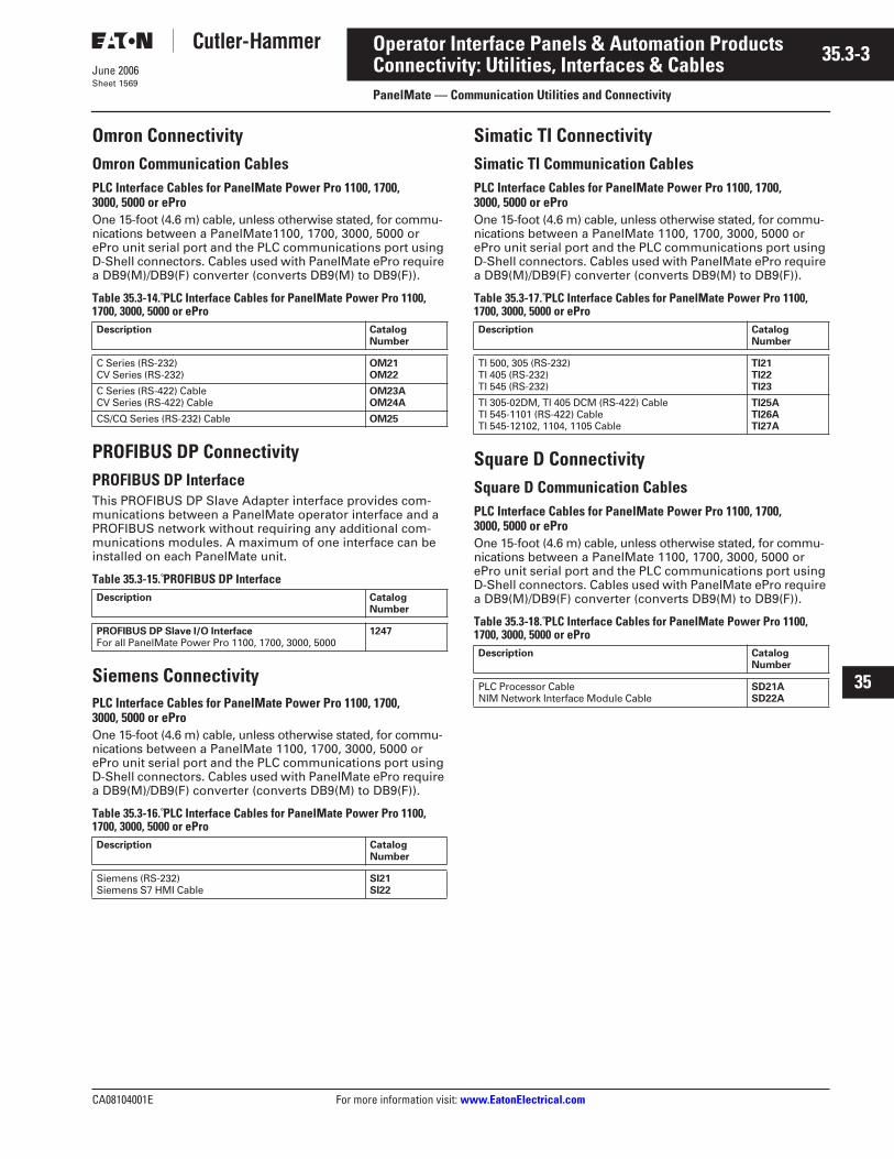
Omron Connectivity
Omron Communication Cables
PLC Interface Cables for PanelMate Power Pro 1100, 1700, 3000, 5000 or ePro
One 15-foot (4.6 m) cable, unless otherwise stated, for commu-nications between a PanelMate1100, 1700, 3000, 5000 or ePro unit serial port and the PLC communications port using D-Shell connectors. Cables used with PanelMate ePro require a DB9(M)/DB9(F) converter (converts DB9(M) to DB9(F)).
Table 35.3-14. PLC Interface Cables for PanelMate Power Pro 1100, 1700, 3000, 5000 or ePro
PROFIBUS DP Connectivity
PROFIBUS DP Interface
This PROFIBUS DP Slave Adapter interface provides com-munications between a PanelMate operator interface and a PROFIBUS network without requiring any additional com-munications modules. A maximum of one interface can be installed on each PanelMate unit.
Table 35.3-15. PROFIBUS DP Interface
Siemens Connectivity
PLC Interface Cables for PanelMate Power Pro 1100, 1700, 3000, 5000 or ePro
One 15-foot (4.6 m) cable, unless otherwise stated, for commu-nications between a PanelMate 1100, 1700, 3000, 5000 or ePro unit serial port and the PLC communications port using D-Shell connectors. Cables used with PanelMate ePro require a DB9(M)/DB9(F) converter (converts DB9(M) to DB9(F)).
Table 35.3-16. PLC Interface Cables for PanelMate Power Pro 1100, 1700, 3000, 5000 or ePro
Simatic TI Connectivity
Simatic TI Communication Cables
PLC Interface Cables for PanelMate Power Pro 1100, 1700, 3000, 5000 or ePro
One 15-foot (4.6 m) cable, unless otherwise stated, for commu-nications between a PanelMate 1100, 1700, 3000, 5000 or ePro unit serial port and the PLC communications port using D-Shell connectors. Cables used with PanelMate ePro require a DB9(M)/DB9(F) converter (converts DB9(M) to DB9(F)).
Table 35.3-17. PLC Interface Cables for PanelMate Power Pro 1100, 1700, 3000, 5000 or ePro
Square D Connectivity
Square D Communication Cables
PLC Interface Cables for PanelMate Power Pro 1100, 1700, 3000, 5000 or ePro
One 15-foot (4.6 m) cable, unless otherwise stated, for commu-nications between a PanelMate 1100, 1700, 3000, 5000 or ePro unit serial port and the PLC communications port using D-Shell connectors. Cables used with PanelMate ePro require a DB9(M)/DB9(F) converter (converts DB9(M) to DB9(F)).
Table 35.3-18. PLC Interface Cables for PanelMate Power Pro 1100, 1700, 3000, 5000 or ePro
Description CatalogNumber
C Series (RS-232)CV Series (RS-232)
OM21OM22
C Series (RS-422) CableCV Series (RS-422) Cable
OM23AOM24A
CS/CQ Series (RS-232) Cable
OM25
Description CatalogNumber
PROFIBUS DP Slave I/O Interface
For all PanelMate Power Pro 1100, 1700, 3000, 5000
1247
Description CatalogNumber
Siemens (RS-232)Siemens S7 HMI Cable
SI21SI22
Description CatalogNumber
TI 500, 305 (RS-232)TI 405 (RS-232)TI 545 (RS-232)
TI21TI22TI23
TI 305-02DM, TI 405 DCM (RS-422) CableTI 545-1101 (RS-422) CableTI 545-12102, 1104, 1105 Cable
TI25ATI26ATI27A
Description CatalogNumber
PLC Processor CableNIM Network Interface Module Cable
SD21ASD22A

35.3-4
For more information visit:
www.EatonElectrical.com
CA08104001E
June 2006
Operator Interface Panels & Automation Products
22
23
24
25
26
27
28
29
30
31
32
33
34
35
36
37
38
39
40
41
42
43
Sheet 1570
This page intentionally left blank.
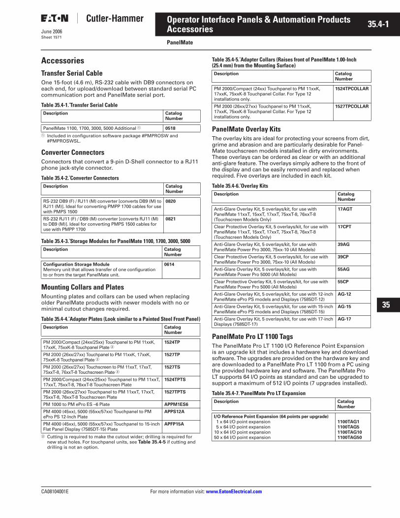
CA08104001E For more information visit:
www.EatonElectrical.com
35.4-1
June 2006
Operator Interface Panels & Automation Products
22
23
24
25
26
27
28
29
30
31
32
33
34
35
36
37
38
39
40
41
42
43
Accessories
PanelMate
Sheet 1571
Accessories
Transfer Serial Cable
One 15-foot (4.6 m), RS-232 cable with DB9 connectors on each end, for upload/download between standard serial PC communication port and PanelMate serial port.
Table 35.4-1. Transfer Serial Cable
1
Included in configuration software package #PMPROSW and #PMPROSWSL.
Converter Connectors
Connectors that convert a 9-pin D-Shell connector to a RJ11 phone jack-style connector.
Table 35.4-2. Converter Connectors
Table 35.4-3. Storage Modules for PanelMate 1100, 1700, 3000, 5000
Mounting Collars and Plates
Mounting plates and collars can be used when replacing older PanelMate products with newer models with no or minimal cutout changes required.
Table 35.4-4. Adapter Plates (Look similar to a Painted Steel Front Panel)
2
Cutting is required to make the cutout wider; drilling is required for new stud holes. For touchpanel units, see
Table 35.4-5
if cutting and drilling is not an option.
Table 35.4-5. Adapter Collars (Raises front of PanelMate 1.00-Inch (25.4 mm) from the Mounting Surface)
PanelMate Overlay Kits
The overlay kits are ideal for protecting your screens from dirt, grime and abrasion and are particularly desirable for Panel-Mate touchscreen models installed in dirty environments. These overlays can be ordered as clear or with an additional anti-glare feature. The overlays simply adhere to the front of the display and can be easily removed and replaced when required. Five overlays are included in each kit.
Table 35.4-6. Overlay Kits
PanelMate Pro LT 1100 Tags
The PanelMate Pro LT 1100 I/O Reference Point Expansion is an upgrade kit that includes a hardware key and download software. The upgrades are provided on the hardware key and are downloaded to a PanelMate Pro LT 1100 from a PC using the provided hardware key and software. The PanelMate Pro LT supports 64 I/O points as standard and can be upgraded to support a maximum of 512 I/O points (7 upgrades installed).
Table 35.4-7. PanelMate Pro LT Expansion
Description CatalogNumber
PanelMate 1100, 1700, 3000, 5000 Additional
1
0518
Description CatalogNumber
RS-232 DB9 (F) / RJ11 (M) converter [converts DB9 (M) to RJ11 (M)]. Ideal for converting PMPP 1700 cables for use with PMPS 1500
0820
RS-232 RJ11 (F) / DB9 (M) converter [converts RJ11 (M) to DB9 (M)]. Ideal for converting PMPS 1500 cables for use with PMPP 1700
0821
Description CatalogNumber
Configuration Storage Module
Memory unit that allows transfer of one configuration to or from the target PanelMate unit.
0614
Description CatalogNumber
PM 2000/Compact (24xx/25xx) Touchpanel to PM 11xxK, 17xxK, 75xxK-8 Touchpanel Plate
2
1524TP
PM 2000 (26xx/27xx) Touchpanel to PM 11xxK, 17xxK, 75xxK-8 Touchpanel Plate
2
1527TP
PM 2000 (26xx/27xx) Touchscreen to PM 11xxT, 17xxT, 75xxT-8, 76xxT-8 Touchscreen Plate
2
1527TS
PM 2000/Compact (24xx/25xx) Touchpanel to PM 11xxT, 17xxT, 75xxT-8, 76xxT-8 Touchscreen Plate
1524TPTS
PM 2000 (26xx/27xx) Touchpanel to PM 11xxT, 17xxT, 75xxT-8, 76xxT-8 Touchscreen Plate
1527TPTS
PM 1000 to PM ePro ES –6 Plate
APPM1ES6
PM 4000 (45xx), 5000 (55xx/57xx) Touchpanel to PM ePro PS 12-Inch Plate
APPS12A
PM 4000 (45xx), 5000 (55xx/57xx) Touchpanel to 15-inch Flat Panel Display (7585DT-15) Plate
APFP15A
Description CatalogNumber
PM 2000/Compact (24xx) Touchpanel to PM 11xxK, 17xxK, 75xxK-8 Touchpanel Collar. For Type 12 installations only.
1524TPCOLLAR
PM 2000 (26xx/27xx) Touchpanel to PM 11xxK, 17xxK, 75xxK-8 Touchpanel Collar. For Type 12 installations only.
1527TPCOLLAR
Description CatalogNumber
Anti-Glare Overlay Kit, 5 overlays/kit, for use with PanelMate 11xxT, 15xxT, 17xxT, 75xxT-8, 76xxT-8 (Touchscreen Models Only)
17AGT
Clear Protective Overlay Kit, 5 overlays/kit, for use with PanelMate 11xxT, 15xxT, 17xxT, 75xxT-8, 76xxT-8 (Touchscreen Models Only)
17CPT
Anti-Glare Overlay Kit, 5 overlays/kit, for use with PanelMate Power Pro 3000, 75xx-10 (All Models)
39AG
Clear Protective Overlay Kit, 5 overlays/kit, for use with PanelMate Power Pro 3000, 75xx-10 (All Models)
39CP
Anti-Glare Overlay Kit, 5 overlays/kit, for use with PanelMate Power Pro 5000 (All Models)
55AG
Clear Protective Overlay Kit, 5 overlays/kit, for use with PanelMate Power Pro 5000 (All Models)
55CP
Anti-Glare Overlay Kit, 5 overlays/kit, for use with 12-inch PanelMate ePro PS models and Displays (7585DT-12)
AG-12
Anti-Glare Overlay Kit, 5 overlays/kit, for use with 15-inch PanelMate ePro PS models and Displays (7585DT-15)
AG-15
Anti-Glare Overlay Kit, 5 overlays/kit, for use with 17-inch Displays (7585DT-17)
AG-17
Description CatalogNumber
I/O Reference Point Expansion (64 points per upgrade)
1 x 64 I/O point expansion5 x 64 I/O point expansion
10 x 64 I/O point expansion50 x 64 I/O point expansion
1100TAG11100TAG51100TAG101100TAG50
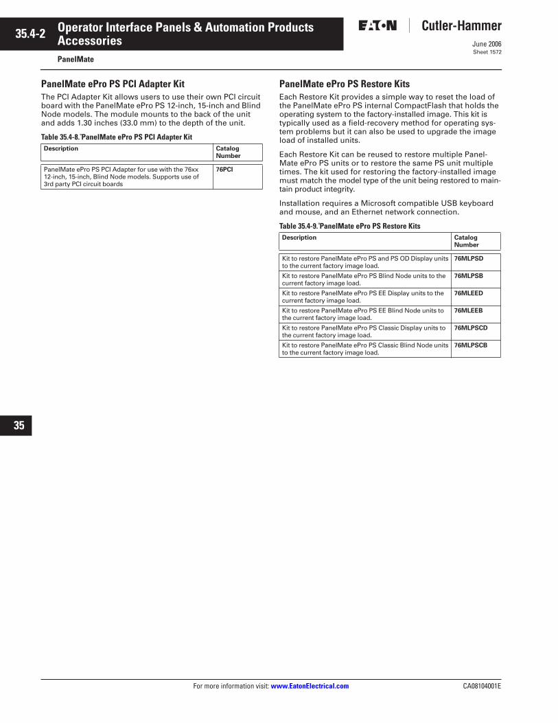
35.4-2
For more information visit:
www.EatonElectrical.com
CA08104001E
June 2006
Operator Interface Panels & Automation Products
22
23
24
25
26
27
28
29
30
31
32
33
34
35
36
37
38
39
40
41
42
43
Accessories
PanelMate
Sheet 1572
PanelMate ePro PS PCI Adapter Kit
The PCI Adapter Kit allows users to use their own PCI circuit board with the PanelMate ePro PS 12-inch, 15-inch and Blind Node models. The module mounts to the back of the unit and adds 1.30 inches (33.0 mm) to the depth of the unit.
Table 35.4-8. PanelMate ePro PS PCI Adapter Kit
PanelMate ePro PS Restore Kits
Each Restore Kit provides a simple way to reset the load of the PanelMate ePro PS internal CompactFlash that holds the operating system to the factory-installed image. This kit is typically used as a field-recovery method for operating sys-tem problems but it can also be used to upgrade the image load of installed units.
Each Restore Kit can be reused to restore multiple Panel-Mate ePro PS units or to restore the same PS unit multiple times. The kit used for restoring the factory-installed image must match the model type of the unit being restored to main-tain product integrity.
Installation requires a Microsoft compatible USB keyboard and mouse, and an Ethernet network connection.
Table 35.4-9. PanelMate ePro PS Restore Kits
Description CatalogNumber
PanelMate ePro PS PCI Adapter for use with the 76xx 12-inch, 15-inch, Blind Node models. Supports use of 3rd party PCI circuit boards
76PCI
Description CatalogNumber
Kit to restore PanelMate ePro PS and PS OD Display units to the current factory image load.
76MLPSD
Kit to restore PanelMate ePro PS Blind Node units to the current factory image load.
76MLPSB
Kit to restore PanelMate ePro PS EE Display units to the current factory image load.
76MLEED
Kit to restore PanelMate ePro PS EE Blind Node units to the current factory image load.
76MLEEB
Kit to restore PanelMate ePro PS Classic Display units to the current factory image load.
76MLPSCD
Kit to restore PanelMate ePro PS Classic Blind Node units to the current factory image load.
76MLPSCB

CA08104001E For more information visit:
www.EatonElectrical.com
35.5-1
June 2006
Operator Interface Panels & Automation Products
22
23
24
25
26
27
28
29
30
31
32
33
34
35
36
37
38
39
40
41
42
43
Application Information
PanelMate Application Information
Sheet 1573
General Application Information
Installation Best Practices
1. Never use foreign objects to acti-vate the touchscreen. Use a hand, gloved hand or stylus. Foreign objects (such as a screwdriver) may cause damage to the touch-screen or scratch the front panel reducing the transmissibility.
2. Use a light touch to activate the touchscreen. Touchscreen activa-tion does not require the same force necessary to activate a mechanical switch.
3. Disconnect this equipment from the power outlet before cleaning. Use a damp cloth. Do not use liquid or spray detergents for cleaning.
4. Do not remove or insert the Com-pactFlash memory card while the PanelMate ePro PS unit is powered up. Doing so may cause damage to the CompactFlash memory and/or processor board.
5. Keep this equipment away from condensing humidity.
6. Put this equipment on a reliable surface during installation. Drop-ping it or letting it fall may cause damage.
7. The openings on the enclosure are for air convection cooling. Protect the equipment from overheating. DO NOT COVER THE OPENINGS.
8. Always install the unit in a vertical orientation for proper cooling
9. Make sure the voltage of the power source is correct before connecting the equipment to the power outlet.
10. Position the power cord so that people cannot step on it. Do not place anything over the power cord.
11. All cautions and warnings on the equipment should be noted.
12. Never pour any liquid into an opening. This may cause fire or electrical shock.
13. Never open the equipment. For safety reasons, the equipment should be opened only by quali-fied service personnel.
14. If one of the following situations arises, get the equipment checked by service personnel:
a. The power cord or plug is damaged.
b. Liquid has penetrated into the equipment.
c. The equipment has been exposed to moisture.
d. The equipment does not work well, or you cannot get it to work according to the user's manual.
e. The equipment has been dropped and damaged.
f. The equipment has obvious signs of breakage.
Power and Ground Overview
The PanelMate operator interface products have been designed to with-stand severe environmental conditions typical in industrial installations. How-ever, certain extreme conditions, such as serious ground faults, have the potential to damage the operator inter-face or cause other damage. In all cases, the installation must protect the operator interface from these extreme conditions and follow local codes and electrical standards and regulations.
For optimum performance #18 AWG (0.82 mm
2
) copper wire should be used for power and ground lead con-nections and if the operator interface unit is installed in areas of poor power quality then power conditioning may be required.
The following recommendations are intended to help protect the operator interface unit from damage due to cur-rent swells, ground faults, or ground potential differentials that can occur in electrical system installations.
■
Use an isolated power supply.
■
Use single point grounding.
■
Install a power supply solely for the PanelMate unit.
■
Use a current-limiting power supply.
■
Add circuit breakers.
Use an Isolated Power Supply
Ac to dc power supplies are typically isolated while dc to dc power supplies are often non-isolated. Check the power supply specifications to ensure that the power supply is fully isolated. If used in a Class I, Div 2 environment, then the external power supply must be appropriately rated.
Use Single Point Grounding
The external power supply and the PanelMate unit should be grounded to the same point. Single point ground-ing should be practiced even when the devices are located in separate enclo-
sures to help prevent ground loop issues.
Install a Power Supply Solely for the PanelMate Operator Interface Unit
If the current external power supply is used for multiple devices, add an external power supply specifically for the PanelMate unit. A separate exter-nal power supply will better protect against system transients and ground potential issues. If used in a Class I, Div 2 environment, the external power supply must be appropriately rated.
Use a Current-Limiting Power Supply
The external power supply should not be able to source more than 5 amperes. If used in a Class I, Div 2 environment, the external power supply must be appropriately rated.
Add Circuit Breakers
Install circuit breakers (Cutler-Hammer Catalog Number WMS2C04) on both the supply and return paths between the PanelMate unit and the external power supply to protect against current swells on the return path. The circuit
breakers should be rated for 10 amperes.

35.5-2
For more information visit:
www.EatonElectrical.com
CA08104001E
June 2006
Operator Interface Panels & Automation Products
22
23
24
25
26
27
28
29
30
31
32
33
34
35
36
37
38
39
40
41
42
43
Application Information
PanelMate Application Information
Sheet 1574
Enclosure
Overview
The enclosure for the PanelMate unit must provide protection against condi-tions that can shorten the unit’s life or cause improper operation:
■
Protection from oil, dust, moisture, corrosive vapors and other airborne contaminants.
■
Protection from ambient temperatures above or below unit specifications.
■
Protection from electromagnetic interference.
Potential Problem Areas
■
Enclosure is too small or PanelMate unit is not mounted in a vertical position for efficient convection cooling.
■
Heat-generating devices cause internal temperature to rise above the operator interface’s ratings.
■
Enclosure is mounted near devices generating high levels of magnetic or electrical interference.
■
Free air space is not present around the outside of the enclosure. This arrangement prevents the enclo-sure’s metal panels from dissipating internal heat.
Enclosure Rating
The front panels of PanelMate units provide a Type 4 or Type 12 rating when mounted in a correspondingly rated enclosure. Some PanelMate models are also rated for Type 4X installations. Make sure the enclosure you choose will meet or exceed your application’s Type rating requirement.
Enclosure Construction
Eaton recommends an enclosure constructed of cold-rolled steel. This will help guard your unit against elec-tromagnetic interference, as well as provide proper structural support and good heat dissipation.
Enclosure Sizing and Unit Positioning
PanelMate in Enclosure
Careful enclosure sizing is important for proper heat dissipation and easy installation and maintenance. For effi-cient convection cooling, free space is needed around the PanelMate unit and the unit should be mounted in a verti-cal position. Convection cooling draws a vertical column of air upward over internal circuitry through the vents in the unit.
In all installations, the cooling air must not exceed the maximum specified ambient temperature.
This determination must be made for the maximum expected plant tempera-ture (maximum temperature of the air surrounding the enclosure).
■
Maintain recommended free space above and below the PanelMate unit (see
Table 35.5-1
).
■
Avoid mounting other heat-generat-ing equipment near the PanelMate unit. If no other location is available, mount the equipment beside or behind the PanelMate unit. If side/rear space is not available, it is pref-erable to mount the other equip-ment above rather than below the PanelMate unit. Be sure to maintain the recommended free space area between the PanelMate unit and the other equipment.
■
Leave room for easy access to circuit boards, wiring/cable connections, and regular maintenance.
Recommended Free Space and Maximum Operating Temperature
The free space area is the space between the PanelMate unit’s electronics and the top or bottom of the enclosure-internal fans, helping provide a uni-form ambient temperature inside the enclosure.
PanelMate
If the inside temperature of the enclo-sure is above the PanelMate unit’s recommended range (see
Table 35.5-1
), you must use filtered fans, heat exchangers, or air conditioners to lower the temperature.
Because hot air rises to the top of an enclosure, the temperature inside can vary greatly from bottom to top. A fan can be used to circulate air within the enclosure to maintain a more uniform temperature. Make sure the magnetic properties of the equipment used to cool the enclosure do not interfere with your PanelMate unit’s operation.
Note:
If an air-purged enclosure is used,it is recommended that the inside/outside pressure differential not exceed.5 PSI.
Table 35.5-1. Recommended Free Space and Maximum Operating Temperature
1
3000 Series Color TFT and 5000 Series units are available in 24 Vdc and 120 Vac versions.
2
50°C with optional PCI adapter attached.
PanelMateModel
Maximum Operating Ambient Temperature
Unit Heat Output
Recommended Free SpaceInches (mm)
1100 Series 50ºC 78 BTU/hr (23 W) 2.00 (50.8) Minimum4.00 (101.6) Minimum
1700 Series 50ºC Grayscale and Color TFT40ºC Color Dual-Scan
78 BTU/hr (23 W)78 BTU/hr (23 W)
2.00 (50.8) Minimum4.00 (101.6) Minimum
3000 Series 50ºC Color TFT
1
102 BTU/hr (30 W at 24 Vdc)
1
6.00 (152.4) Minimum
50ºC Color TFT
1
119 BTU/hr (35 W at 120 Vac)
1
6.00 (152.4) Minimum
5000 Series 50ºC 102 BTU/hr (30 W at 24 Vdc)
1
6.00 (152.4) Minimum
50ºC 137 BTU/hr (40 W at 120 Vac)
1
6.00 (152.4) Minimum
ePro 50ºC 116 BTU/hr (34 W at 24 Vdc)) 4.00 (101.6) Minimum
ePro ES 50ºC 6-Inch – 52 BTU/hr (15 W) 2.00 (50.8) Minimum
ePro PS, EE,PS Classic
55ºC
2
8-Inch – 96 BTU/hr (28 W)12-Inch – 109 BTU/hr (32 W)15-Inch – 150 BTU/hr (44 W)BN – 68 BTU/hr (20 W)
4.00 (101.6) Minimum
ePro PS OD 60ºC
2
12-Inch – 109 BTU/hr (32 W) 4.00 (101.6) Minimum

CA08104001E For more information visit:
www.EatonElectrical.com
35.5-3
June 2006
Operator Interface Panels & Automation Products
22
23
24
25
26
27
28
29
30
31
32
33
34
35
36
37
38
39
40
41
42
43
Application Information
PanelMate Application Information
Sheet 1575
Enclosure Size vs. Average Internal Temperature Rise
Table 35.5-2
makes the following assumptions:
■
Enclosure is fabricated from cold-rolled steel.
■
All sides of the enclosure are not insulated (freestanding).
■
Recommended minimum clearance between the PanelMate unit and the top and bottom of the enclosure.
■
No other heat-generating equip-ment is installed in the enclosure.
Note:
The temperature rise shown repre-sents the temperature rise in the enclosure above the outside temperature. For exam-ple, if the temperature outside the enclosure is 35ºC and the temperature rise in the enclosure is 10ºC, then the average temper-ature inside the enclosure will be 45ºC.
The following sizing table is offered as an aid in the selection of enclosures to be used with PanelMate products. Eaton offers no guarantee or warranty to the specific applicability of this table as actual conditions may vary and
methods of the use of our products are beyond our control. For specific infor-mation about enclosure selection and cooling methods, contact your enclo-sure vendor.
Table 35.5-2. Suggested PanelMate Enclosure Sizes
Panel Type
Size inInches (mm)
Temperature Rise(Degrees C)
1100 with Keypad or Touchscreen
16.00 x 16.00 x 4.00 (406.4 x 406.4 x 101.6)16.00 x 16.00 x 6.00 (406.4 x 406.4 x 152.4)20.00 x 16.00 x 6.00 (508.0 x 406.4 x 152.4)
10.8ºC 9.3ºC 7.7ºC
1100 with Touchscreen
12.00 x 12.00 x 6.00 (304.8 x 304.8 x 152.4)12.00 x 14.00 x 6.00 (304.8 x 355.6 x 152.4)
14.4ºC12.8ºC
1700 with Keypad or Touchscreen
16.00 x 16.00 x 4.00 (406.4 x 406.4 x 101.6)16.00 x 16.00 x 6.00 (406.4 x 406.4 x 152.4)20.00 x 16.00 x 6.00 (508.0 x 406.4 x 152.4)
10.8ºC 9.3ºC 7.7ºC
1700 with Touchscreen
12.00 x 12.00 x 6.00 (304.8 x 304.8 x 152.4)12.00 x 14.00 x 6.00 (304.8 x 355.6 x 152.4)
14.4ºC12.8ºC
All 3000 (24 Vdc)
24.00 x 20.00 x 6.00 (609.6 x 508.8 x 152.4)24.00 x 24.00 x 6.00 (609.6 x 609.6 x 152.4)
6.7ºC 5.3ºC
All 3000 (120 Vac)
24.00 x 20.00 x 8.00 (609.6 x 508.8 x 203.2)24.00 x 24.00 x 8.00 (609.6 x 609.6 x 203.2)
7.2ºC 6.7ºC
5000 with Keypad (24 Vdc)
30.00 x 24.00 x 8.00 (762.0 x 609.6 x 203.2)30.00 x 24.00 x 10.00 (762.0 x 609.6 x 254.0)
4.2ºC 3.6ºC
5000 with Keypad (120 Vac)
30.00 x 24.00 x 8.00 (762.0 x 609.6 x 203.2)30.00 x 24.00 x 10.00 (762.0 x 609.6 x 254.0)
6.0ºC 5.6ºC
5000 with Touchscreen (24 Vdc)
24.00 x 24.00 x 8.00 (609.6 x 609.6 x 203.2)24.00 x 24.00 x 10.00 (609.6 x 609.6 x 254.0)24.00 x 30.00 x 8.00 (609.6 x 762.0 x 203.2)
5.3ºC 4.8ºC 4.2ºC
5000 with Touchscreen (120 Vac)
24.00 x 24.00 x 8.00 (609.6 x 609.6 x 203.2)24.00 x 24.00 x 10.00 (609.6 x 609.6 x 254.0)24.00 x 30.00 x 8.00 (609.6 x 762.0 x 203.2)
7.2ºC 6.7ºC 6.1ºC
ePro
16.00 x 16.00 x 8.00 (406.4 x 406.4 x 203.2)20.00 x 16.00 x 8.00 (508.0 x 406.4 x 203.2)20.00 x 16.00 x 10.00 (508.0 x 406.4 x 254.0)
13.0ºC11.0ºC 9.5ºC
20.00 x 20.00 x 10.00 (508.0 x 508.0 x 254.0)24.00 x 20.00 x 10.00 (609.6 x 508.0 x 254.0)24.00 x 24.00 x 10.00 (609.6 x 609.6 x 254.0)
7.5ºC 6.0ºC 6.0ºC
ePro ES 6-Inch 10.00 x 10.00 x 4.00 (254.0 x 254.0 x 101.6)12.00 x 12.00 x 4.00 (304.8 x 304.8 x 101.6)12.00 x 12.00 x 6.00 (304.8 x 304.8 x 152.4)12.00 x 16.00 x 6.00 (304.8 x 406.4 x 152.4)16.00 x 16.00 x 6.00 (406.4 x 406.4 x 152.4)
17.0ºC11.0ºC 8.5ºC 8.0ºC 7.0ºC
ePro PS 8-Inch 16.00 x 20.00 x 6.00 (406.4 x 508.0 x 152.4)20.00 x 20.00 x 6.00 (508.0 x 508.0 x 152.4)20.00 x 24.00 x 6.00 (508.0 x 609.6 x 152.4)20.00 x 24.00 x 8.00 (508.0 x 609.6 x 203.2)
10.5ºC 8.0ºC 7.0ºC 5.5ºC
ePro PS 12-Inch 20.00 x 20.00 x 6.00 (508.0 x 508.0 x 152.4)20.00 x 24.00 x 6.00 (508.0 x 609.6 x 152.4)20.00 x 20.00 x 8.00 (508.0 x 508.0 x 203.2)20.00 x 24.00 x 8.00 (508.0 x 609.6 x 203.2)
9.0ºC 8.0ºC 8.0ºC 7.0ºC
ePro PS 15-Inch 20.00 x 24.00 x 6.00 (508.0 x 609.6 x 152.4)20.00 x 20.00 x 8.00 (508.0 x 508.0 x 203.2)20.00 x 24.00 x 8.00 (508.0 x 609.6 x 203.2)24.00 x 24.00 x 8.00 (609.6 x 609.6 x 203.2)
11.0ºC11.0ºC 9.0ºC 8.0ºC
ePro PS Blind Node 16.00 x 20.00 x 4.00 (406.4 x 508.0 x 101.6)16.00 x 20.00 x 6.00 (406.4 x 508.0 x 152.4)20.00 x 20.00 x 6.00 (508.0 x 508.0 x 152.4)20.00 x 24.00 x 6.00 (508.0 x 609.6 x 152.4)
9.0ºC 7.0ºC 5.5ºC 5.0ºC

35.5-4
For more information visit:
www.EatonElectrical.com
CA08104001E
June 2006
Operator Interface Panels & Automation Products
22
23
24
25
26
27
28
29
30
31
32
33
34
35
36
37
38
39
40
41
42
43
Application Information
Communication Interface
Sheet 1576
Communication Overview
This section contains a summary of several popular communication inter-face options. Each summary provides specific recommendations, guidelines and installation tips.
Potential Problem Areas
Improper grounding of communica-tions cable, causing excessive radiated emissions.
■
Incorrect cable or pin-out, improper or lack of termination on PanelMate units located at the end of a commu-nications network.
■
Failure to maintain minimum/maxi-mum cable lengths between nodes on a communications network.
■
Exceeding recommended cable or total network distance.
A variety of communication interface options are available for PanelMate products.
Options include:
■
RS-232 and RS-422 based communications.
■
RS-485 multi-drop communications.
■
“Open” multi-drop networks (examples: DeviceNet, PROFIBUS).
■
Proprietary PLC networks (examples: Allen-Bradley Data Highway, GE Fanuc GEnius I/O, Modicon Modbus Plus).
Eaton does not recommend any specific communications option. Your choice should be based on the require-ments of your total control system. The communications option you choose determines the precautions you need to take when installing and connecting your PanelMate unit.
For easy reference, this chapter con-tains a summary of several popular communication interface options. Each summary provides specific rec-ommendations, guidelines and instal-lation tips.
Note:
Low signal level conductors (Cate-gory 2) have a low tolerance for induced electrical noise. Electrical noise can cause a wide range of communications problems resulting in slow or error-prone PanelMate operation. Be certain to follow all of the installation recommendations for the com-munication option you choose. Also, be sure to follow good wiring placement prac-tices as outlined in “Cable Segregation and Placement.”
Communication Interface Options
RS-232 Communications
■
Recommended distance:
❑
Up to 50 feet (15.2 m)
■
Recommended cable type/size:
❑
24 gauge, shielded pair
RS-232 Grounding Recommendations
Grounding of the communication cable shield at both ends will provide the most immunity to high frequency electrical interference. However, the introduction of low frequency interfer-ence by high ground currents in the shield may require grounding only one end. Should this approach result in unacceptable high frequency interfer-ence, then an RS-422 interface should be considered. For RS-232 communi-cations, the maximum rated input volt-age at the PanelMate unit’s serial port is –30 to +30 volts.
RS-232 Shielding Recommendations
Application: Short or Long Runs in LOW or HIGH Noise Environment with INSIGNIFI-CANT Levels of Low Frequency Ground Dif-ferential Voltage Between Connected Units
A good quality shielded cable consist-ing of twisted pairs for the required communication wires and logic com-mon is recommended. An unshielded line is not recommended because the unshielded connectors may act as an antenna resulting in radiated emis-sions that may exceed the CE required limit. Additionally, shielded cable pro-vides greater ESD protection. The shield should be connected directly to the chassis of the interconnected units at both ends. The connector housing should contact the cable shield uni-formly around the entire 360-degree periphery of the housing cable entry opening. Never connect the shield by way of a drain wire pigtail unless abso-lutely necessary. If a pigtail is required, the shield should be terminated as close as possible to the connector to minimize the pigtail length.
Application: Short or Long Runs in LOW Noise Environment with HIGH Levels of Low Frequency Ground Differential Voltage Between Connected Units
A good quality shielded cable consist-ing of twisted pairs for the required communication wires and logic com-mon is recommended. The shield should be connected directly to the chassis of one of the interconnected units (one end only). Never connect the shield by way of a drain wire pig-tail unless absolutely necessary. If a pigtail is required, the shield should be terminated as close as possible to the connector to minimize the pigtail length.
Application: Short or Long Runs in HIGH Noise Environment with HIGH Levels of Low Frequency Ground Differential Voltage Between Connected Units
A good quality shielded cable consisting of twisted pairs for the required com-munication wires and logic common is recommended. The shield should be connected directly to the chassis of one of the interconnected units and ac-coupled through a 0.01 µf capacitor at the other end to the chassis of the second unit. The connector housing should contact the cable shield uni-formly around the entire 360-degree periphery of the housing cable entry opening. Attaching the capacitor at the ac-coupled end will require some ingenuity to achieve a secure connec-tion at both the shield and chassis while keeping the capacitor lead length as short as possible.

CA08104001E For more information visit:
www.EatonElectrical.com
35.5-5
June 2006
Operator Interface Panels & Automation Products
22
23
24
25
26
27
28
29
30
31
32
33
34
35
36
37
38
39
40
41
42
43
Application Information
Communication Interface
Sheet 1577
RS-422 Communications
■
Recommended distance:
❑
Up to 4000 ft. (1219.2 m)
❑
Up to 2000 ft. (609.6 m) for RS-422 connected to A-B Channel 0
■
Recommended cable type/size:
❑
22 gauge, shielded pair
RS-422 Grounding Recommendations
This balanced interface will operate with common mode dc or peak ac voltage differentials of –7 to +7 volts between grounds at each end of the cable. In cases where the common mode voltage approaches either extreme, the system may operate properly when the shield is grounded at only one end of the cable. However, this arrangement will make the system susceptible to high frequency interfer-ence. If the systems will not operate properly due to high frequency inter-ference and grounding the cable shield at both ends is ineffective, then total isolation must be considered or elimi-nate ground potentials in your plant.
RS-422 Shielding Recommendations
Application: Short or Long Runs in LOW or HIGH Noise Environment with INSIGNIFI-CANT Levels of Low Frequency Ground Dif-ferential Voltage Between Connected Units
A good quality shielded cable consist-ing of twisted pairs for the required communication wires and logic com-mon is recommended. An unshielded line is not recommended because the unshielded connectors may act as an antenna resulting in radiated emis-sions that may exceed the CE mark required limit. Additionally, shielded cable provides greater ESD protection. The shield should be connected directly to the chassis of the intercon-nected units at both ends. The connec-tor housing should contact the cable shield uniformly around the entire 360-degree periphery of the housing cable entry opening. Never connect the shield by way of a drain wire pigtail unless absolutely necessary. If a pigtail is required, the shield should be termi-nated as close as possible to the con-nector to minimize the pigtail length.
Application: Short or Long Runs in LOW Noise Environment with HIGH Levels of Low Frequency Ground Differential Voltage Between Connected Units
A good quality shielded cable consist-ing of twisted pairs for the required communication wires and logic com-mon is recommended. The shield should be connected directly to the chassis of one of the interconnected units (one end only). Never connect the shield by way of a drain wire pig-tail unless absolutely necessary. If a pigtail is required, the shield should be terminated as close as possible to the connector to minimize the pigtail length.
Application: Short or Long Runs in HIGH Noise Environment with HIGH Levels of Low Frequency Ground Differential Voltage Between Connected Units
A good quality shielded cable consist-ing of twisted pairs for the required communication wires and logic com-mon is recommended. The shield should be connected directly to the chassis of one of the interconnected units and ac coupled through a 0.01 µf capacitor at the other end to the chas-sis of the second unit. The connector housing should contact the cable shield uniformly around the entire 360-degree periphery of the housing cable entry opening. Attaching the capacitor at the ac-coupled end will require some ingenuity to achieve a secure connection at both the shield and chassis while keeping the capacitor lead length as short as possible.
RS-485 Multi-drop Communications:
■
Recommended distance:
❑
Up to 4000 ft. (1219.2 m)
❑
Up to 2000 ft. (609.6 m) for RS-485 connected to A-B Channel 0
■
Recommended cable type/size:
❑
22 gauge, shielded pair
Note:
See separate for Allen-Bradley DH-485 Communications.
This network is an extension of RS-422 and is used for the distribution of data between multiple system components and peripherals over distances up to 4000 ft. (1219.2 m). This system will tolerate common mode voltage differ-entials from –7 to +12 volts. For more information refer to the EIA RS-485 Standard.
RS-485 Shielding Recommendations
Application: Short or Long Runs in LOW or HIGH Noise Environment with INSIGNIFI-CANT Levels of Low Frequency Ground Dif-ferential Voltage Between Connected Units
A good quality shielded cable consist-ing of twisted pairs for the required communication wires and logic com-mon is recommended. An unshielded line is not recommended because the unshielded connectors may act as an antenna resulting in radiated emis-sions that may exceed the CE mark required limit. Additionally, shielded cable provides greater ESD protection. The shield should be connected directly to the chassis of the intercon-nected units at both ends. The connec-tor housing should contact the cable shield uniformly around the entire 360-degree periphery of the housing cable entry opening. Never connect the shield by way of a drain wire pigtail unless absolutely necessary. If a pigtail is required, the shield should be termi-nated as close as possible to the con-nector to minimize the pigtail length.
Application: Short or Long Runs in LOW Noise Environment with HIGH Levels of Low Frequency Ground Differential Voltage Between Connected Units
A good quality shielded cable consist-ing of twisted pairs for the required communication wires and logic com-mon is recommended. The shield should be connected directly to the chassis of one of the interconnected units (one end only). Never connect the shield by way of a drain wire pig-tail unless absolutely necessary. If a pigtail is required, the shield should be terminated as close as possible to the connector to minimize the pigtail length.
Application: Short or Long Runs in HIGH Noise Environment with HIGH Levels of Low Frequency Ground Differential Voltage Between Connected Units
A good quality shielded cable consist-ing of twisted pairs for the required communication wires and logic com-mon is recommended. The shield should be connected directly to the chassis of one of the interconnected units and ac coupled through a 0.01 µf capacitor at the other end to the chas-sis of the second unit. The connector housing should contact the cable shield uniformly around the entire 360-degree periphery of the housing cable entry opening. Attaching the capacitor at the ac-coupled end will require some ingenuity to achieve a secure connection at both the shield and chassis while keeping the capacitor lead length as short as possible.
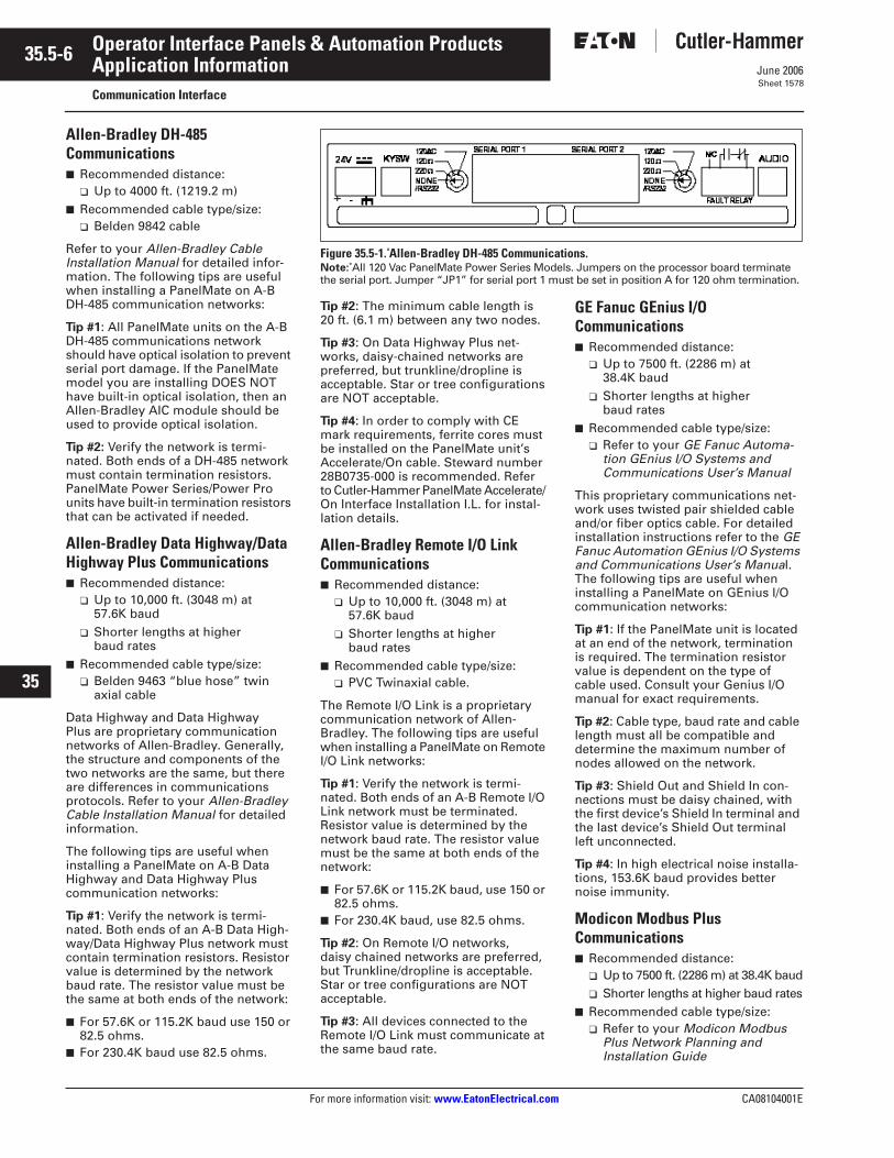
35.5-6
For more information visit:
www.EatonElectrical.com
CA08104001E
June 2006
Operator Interface Panels & Automation Products
22
23
24
25
26
27
28
29
30
31
32
33
34
35
36
37
38
39
40
41
42
43
Application Information
Communication Interface
Sheet 1578
Allen-Bradley DH-485 Communications
■
Recommended distance:
❑
Up to 4000 ft. (1219.2 m)
■
Recommended cable type/size:
❑
Belden 9842 cable
Refer to your
Allen-Bradley Cable Installation
Manual
for detailed infor-mation. The following tips are useful when installing a PanelMate on A-B DH-485 communication networks:
Tip #1: All PanelMate units on the A-B DH-485 communications network should have optical isolation to prevent serial port damage. If the PanelMate model you are installing DOES NOT have built-in optical isolation, then an Allen-Bradley AIC module should be used to provide optical isolation.
Tip #2: Verify the network is termi-nated. Both ends of a DH-485 network must contain termination resistors. PanelMate Power Series/Power Pro units have built-in termination resistors that can be activated if needed.
Allen-Bradley Data Highway/Data Highway Plus Communications■ Recommended distance:
❑ Up to 10,000 ft. (3048 m) at 57.6K baud
❑ Shorter lengths at higher baud rates
■ Recommended cable type/size:❑ Belden 9463 “blue hose” twin
axial cable
Data Highway and Data Highway Plus are proprietary communication networks of Allen-Bradley. Generally, the structure and components of the two networks are the same, but there are differences in communications protocols. Refer to your Allen-Bradley Cable Installation Manual for detailed information.
The following tips are useful when installing a PanelMate on A-B Data Highway and Data Highway Plus communication networks:
Tip #1: Verify the network is termi-nated. Both ends of an A-B Data High-way/Data Highway Plus network must contain termination resistors. Resistor value is determined by the network baud rate. The resistor value must be the same at both ends of the network:
■ For 57.6K or 115.2K baud use 150 or 82.5 ohms.
■ For 230.4K baud use 82.5 ohms.
Figure 35.5-1. Allen-Bradley DH-485 Communications.Note: All 120 Vac PanelMate Power Series Models. Jumpers on the processor board terminate the serial port. Jumper “JP1” for serial port 1 must be set in position A for 120 ohm termination.
Tip #2: The minimum cable length is 20 ft. (6.1 m) between any two nodes.
Tip #3: On Data Highway Plus net-works, daisy-chained networks are preferred, but trunkline/dropline is acceptable. Star or tree configurations are NOT acceptable.
Tip #4: In order to comply with CE mark requirements, ferrite cores must be installed on the PanelMate unit’s Accelerate/On cable. Steward number 28B0735-000 is recommended. Refer to Cutler-Hammer PanelMate Accelerate/ On Interface Installation I.L. for instal-lation details.
Allen-Bradley Remote I/O Link Communications■ Recommended distance:
❑ Up to 10,000 ft. (3048 m) at 57.6K baud
❑ Shorter lengths at higher baud rates
■ Recommended cable type/size:❑ PVC Twinaxial cable.
The Remote I/O Link is a proprietary communication network of Allen-Bradley. The following tips are useful when installing a PanelMate on Remote I/O Link networks:
Tip #1: Verify the network is termi-nated. Both ends of an A-B Remote I/O Link network must be terminated. Resistor value is determined by the network baud rate. The resistor value must be the same at both ends of the network:
■ For 57.6K or 115.2K baud, use 150 or 82.5 ohms.
■ For 230.4K baud, use 82.5 ohms.
Tip #2: On Remote I/O networks, daisy chained networks are preferred, but Trunkline/dropline is acceptable. Star or tree configurations are NOT acceptable.
Tip #3: All devices connected to the Remote I/O Link must communicate at the same baud rate.
GE Fanuc GEnius I/O Communications■ Recommended distance:
❑ Up to 7500 ft. (2286 m) at 38.4K baud
❑ Shorter lengths at higher baud rates
■ Recommended cable type/size:❑ Refer to your GE Fanuc Automa-
tion GEnius I/O Systems and Communications User’s Manual
This proprietary communications net-work uses twisted pair shielded cable and/or fiber optics cable. For detailed installation instructions refer to the GE Fanuc Automation GEnius I/O Systems and Communications User’s Manual. The following tips are useful when installing a PanelMate on GEnius I/O communication networks:
Tip #1: If the PanelMate unit is located at an end of the network, termination is required. The termination resistor value is dependent on the type of cable used. Consult your Genius I/O manual for exact requirements.
Tip #2: Cable type, baud rate and cable length must all be compatible and determine the maximum number of nodes allowed on the network.
Tip #3: Shield Out and Shield In con-nections must be daisy chained, with the first device’s Shield In terminal and the last device’s Shield Out terminal left unconnected.
Tip #4: In high electrical noise installa-tions, 153.6K baud provides better noise immunity.
Modicon Modbus Plus Communications■ Recommended distance:
❑ Up to 7500 ft. (2286 m) at 38.4K baud❑ Shorter lengths at higher baud rates
■ Recommended cable type/size:❑ Refer to your Modicon Modbus
Plus Network Planning andInstallation Guide

CA08104001E For more information visit: www.EatonElectrical.com
35.5-7June 2006
Operator Interface Panels & Automation Products
22
23
24
25
26
27
28
29
30
31
32
33
34
35
36
37
38
39
40
41
42
43
Application InformationCommunication Interface
Sheet 1579
This proprietary communications network consists of twisted pair shielded cable extending up to 1500 ft. (457.2 m) with up to 32 nodes. For detailed installation instructions refer to your Modicon Mod-bus Plus Network Planning and Installa-tion Guide. The following tips are useful when installing a PanelMate on Modicon Modbus Plus communication networks:
Tip #1: Trunkline/dropline is the only acceptable network configuration. Star or tree configurations are NOT acceptable.
Tip #2: A drop cable is used to connect the PanelMate unit to the trunkline tap. The drop cable is equipped with a ground lug that must be connected to PanelMate unit’s panel ground.
Tip #3: The minimum cable length between nodes must be at least 10 ft. (3 m).
DeviceNet Communications■ Recommended distance:
❑ Up to 1640 ft. (499.9 m) at 125K baud■ Recommended cable type/size:
❑ Refer to your Cutler-Hammer DeviceNet Installation Guide
DeviceNet is a non-proprietary commu-nications network consisting of 5 con-ductor, shielded cable in trunkline (thick) and dropline (thin) styles. Up to 64 nodes can be installed on the network. Refer to Eaton’s Cutler-Hammer’s DeviceNet Planning and Installation Guide for detailed information on DeviceNet networks. The following tips are useful when installing a PanelMate on a DeviceNet communication network:
Tip #1: The dropline to the PanelMate unit must not exceed 20 ft. (6.1 m).
Tip #2: If the PanelMate unit is the last node on the network, termination is required. Install a 120 ohm terminator in the unused plug of the connector, or install a 120 ohm resistor between pins 4 and 2 of the PhoenixT connector.
Tip #3: The PanelMate unit does not draw power from, or supply power to the network. It is not necessary to make the V+ connection, but you should do so to secure the wires and prevent shorting.
Tip #4: In all PanelMate units, the DeviceNet signal ground is isolated from chassis ground. In locations where problems are caused by high electrical noise, you can change the jumper setting on the PanelMate unit’s DeviceNet communications card to connect signal ground to chassis ground.
Refer to Eaton’s Cutler-Hammer’s Pan-elMate DeviceNet Interface Installation I.L. for detailed jumper information.
Tip #5: In order to comply with CE mark requirements, ferrite cores must be installed on the PanelMate unit’s drop line. Steward number 28B1020-100 is recommended for thick line installa-tions. Steward number 28B0735-000 is recommended for thin line installations.
Refer to Eaton’s Cutler-Hammer’s PanelMate DeviceNet Interface Instal-lation I.L. for installation details.
PROFIBUS DP Communications■ Recommended distance:
❑ Up to 3278 ft. (999.1 m) at 93.7K baud■ Recommended cable type/size:
❑ 22 gauge, shielded pair
PROFIBUS DP is based on RS-485 network technology. A PROFIBUS DP network may have up to 126 nodes, but maximum length of the network is determined by baud rate.
PROFIBUS DP Shielding RecommendationsA good quality shielded cable consisting of twisted pairs for the required commu-nication wires and logic common is rec-ommended. An unshielded line is not recommended because the unshielded connectors may act as an antenna resulting in radiated emissions that may exceed the CE mark required limit. Addi-tionally, shielded cable provides greater ESD protection. The shield should be connected directly to the chassis of the interconnected units at both ends. The connector housing should contact the cable shield uniformly around the entire 360-degree periphery of the housing cable entry opening. Never connect the shield by way of a drain wire pigtail unless absolutely necessary. If a pigtail is required, the shield should be termi-nated as close as possible to the con-nector to minimize the pigtail length.
Using PanelMate on a PROFIBUS DP NetworkThe following tips are useful when installing a PanelMate on a PROFIBUS DP communication network:
Tip #1: The PROFIBUS network must be terminated at both ends of every seg-ment. The termination must be powered at all times.
Tip #2: As the PROFIBUS DP network allows daisy-chained connections, wiring for Signal A and Signal B must remain consistent throughout the seg-ment. It is suggested that the green wire is used for Signal A and the red wire is used for Signal B.
Cable SegregationThe low power cabling used for PLC and PC-based control systems is very susceptible to electrical noise gener-ated by high power conductors. Even when protected by conduit, noise can interfere with your communication lines and networks. Therefore it is important to segregate conductors according to their type.
Category Description ExamplesCategory 1 High Power Conductors —These conductors can cause electrical noise in Category 2 conductors when in close proximity. Are more tolerant of electrical noise than Category 2. Reference: NECT article 725 Class I. Reference IEEE level 3 and 4 ac power lines.
High Power Digital ac and dc Lines — Typically these conductors are used to connect hard-contact switches, relays, solenoids, motors, generators and arc welders.
Category 2 Low Signal Level Conductors — These conductors are less tolerant of electrical noise, how-ever, they cause less noise in adjacent conductors. Reference NEC Article 725 Class 2, Class 3. Reference IEEE level 1 and level 2 Communication cables — Ethernet, PLC networks, etc.
Low Power Digital ac and dc I/O Lines — Typically these conductors are used to connect PLCs and related modules with PanelMate operator stations.
Cable PlacementThe following guidelines should be used when installing your communication cables:
■ All Category 2 cables should be shielded and routed in a separate conduit or raceway from Category 1 cables.
■ Route Category 2 cables at least 1 ft. (.3 m) from 120 Vac power lines.
■ Route Category 2 cables at least 2 ft. (.6 m) from 240 Vac power lines.
■ Route Category 2 cables at least 3 ft. (.9 m) from 480 Vac power lines.
■ Route Category 2 cables at least 5 ft. (1.5 m) from high voltage enclosures.
■ If a Category 2 cable must cross Category 1 cables, it should cross at a right angle.
■ If Category 2 cable is enclosed in metal conduit or a metal raceway, electrical continuity must be main-tained along the entire length of the conduit/raceway installation, including entry into the enclosure.
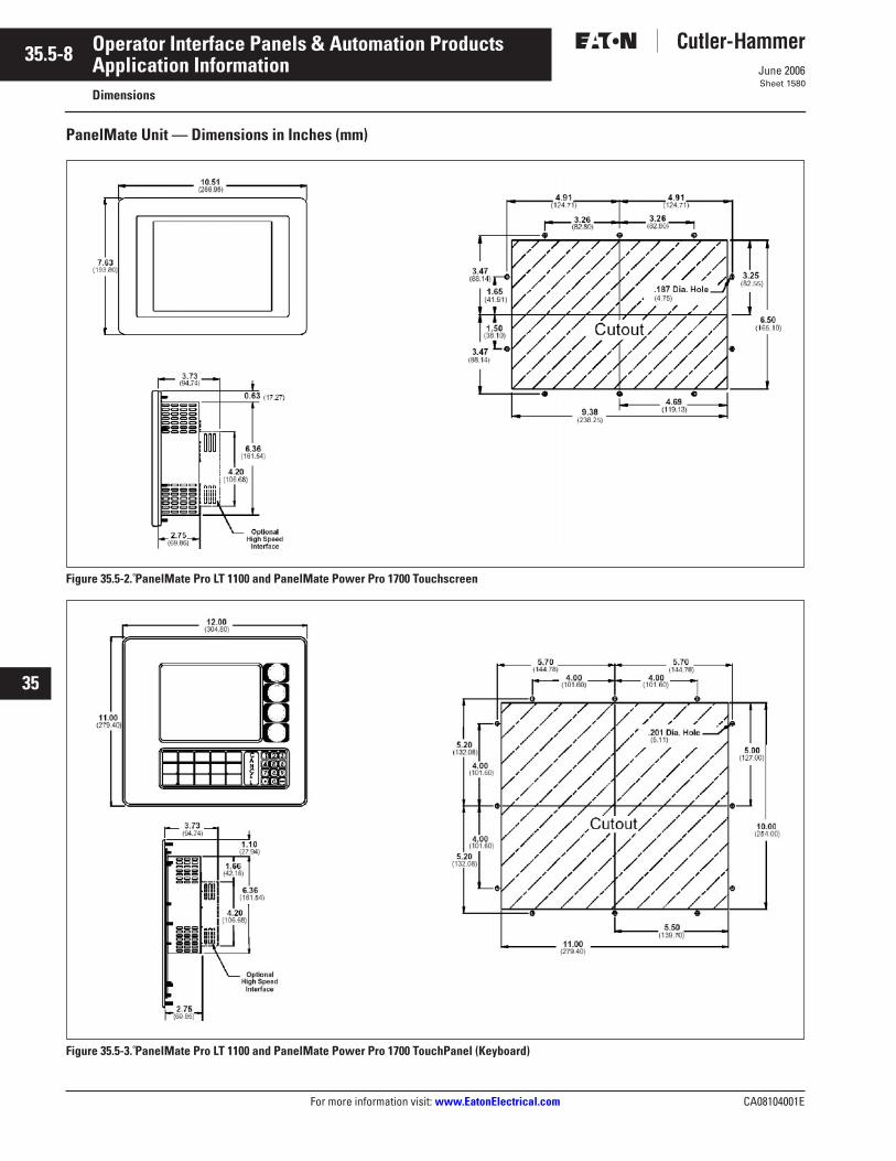
35.5-8
For more information visit: www.EatonElectrical.com CA08104001E
June 2006
Operator Interface Panels & Automation Products
22
23
24
25
26
27
28
29
30
31
32
33
34
35
36
37
38
39
40
41
42
43
Application InformationDimensions
Sheet 1580
PanelMate Unit — Dimensions in Inches (mm)
Figure 35.5-2. PanelMate Pro LT 1100 and PanelMate Power Pro 1700 Touchscreen
Figure 35.5-3. PanelMate Pro LT 1100 and PanelMate Power Pro 1700 TouchPanel (Keyboard)
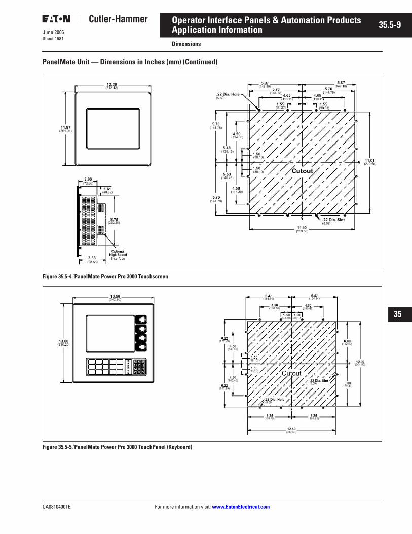
CA08104001E For more information visit: www.EatonElectrical.com
35.5-9June 2006
Operator Interface Panels & Automation Products
22
23
24
25
26
27
28
29
30
31
32
33
34
35
36
37
38
39
40
41
42
43
Application InformationDimensions
Sheet 1581
PanelMate Unit — Dimensions in Inches (mm) (Continued)
Figure 35.5-4. PanelMate Power Pro 3000 Touchscreen
Figure 35.5-5. PanelMate Power Pro 3000 TouchPanel (Keyboard)
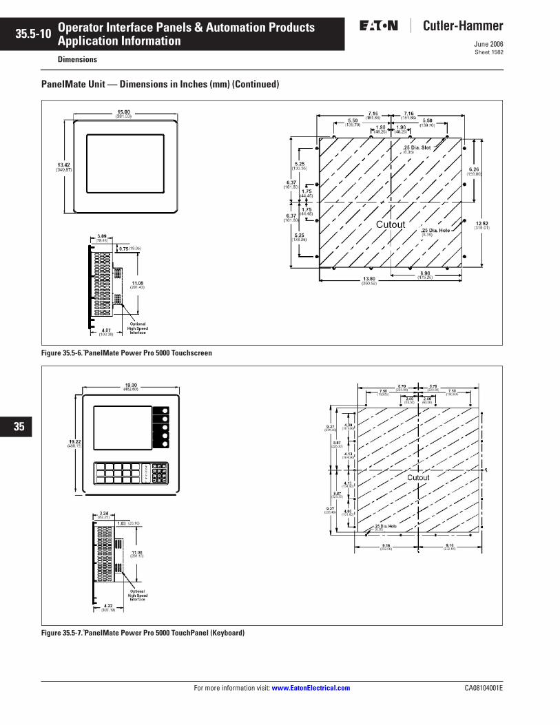
35.5-10
For more information visit: www.EatonElectrical.com CA08104001E
June 2006
Operator Interface Panels & Automation Products
22
23
24
25
26
27
28
29
30
31
32
33
34
35
36
37
38
39
40
41
42
43
Application InformationDimensions
Sheet 1582
PanelMate Unit — Dimensions in Inches (mm) (Continued)
Figure 35.5-6. PanelMate Power Pro 5000 Touchscreen
Figure 35.5-7. PanelMate Power Pro 5000 TouchPanel (Keyboard)
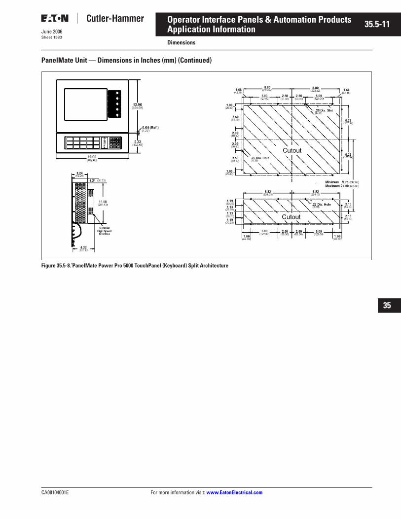
CA08104001E For more information visit: www.EatonElectrical.com
35.5-11June 2006
Operator Interface Panels & Automation Products
22
23
24
25
26
27
28
29
30
31
32
33
34
35
36
37
38
39
40
41
42
43
Application InformationDimensions
Sheet 1583
PanelMate Unit — Dimensions in Inches (mm) (Continued)
Figure 35.5-8. PanelMate Power Pro 5000 TouchPanel (Keyboard) Split Architecture
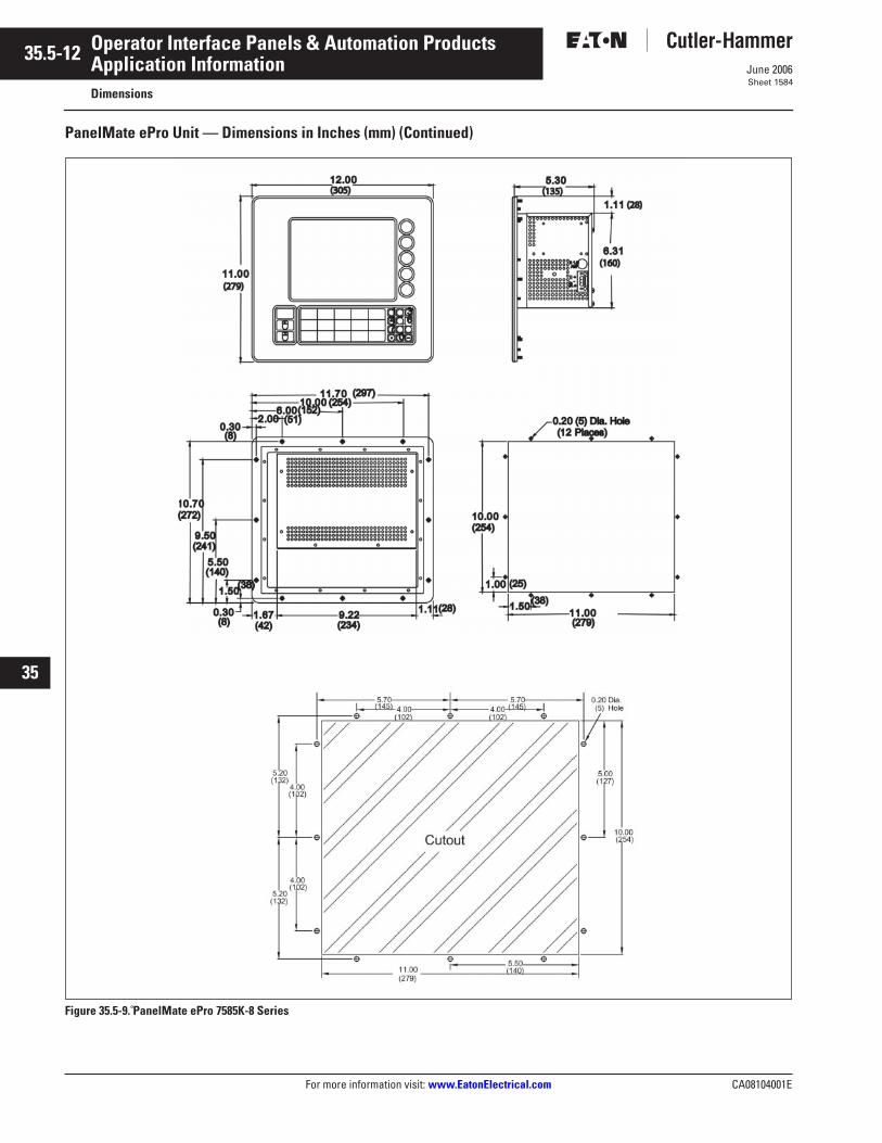
35.5-12
For more information visit: www.EatonElectrical.com CA08104001E
June 2006
Operator Interface Panels & Automation Products
22
23
24
25
26
27
28
29
30
31
32
33
34
35
36
37
38
39
40
41
42
43
Application InformationDimensions
Sheet 1584
PanelMate ePro Unit — Dimensions in Inches (mm) (Continued)
Figure 35.5-9. PanelMate ePro 7585K-8 Series
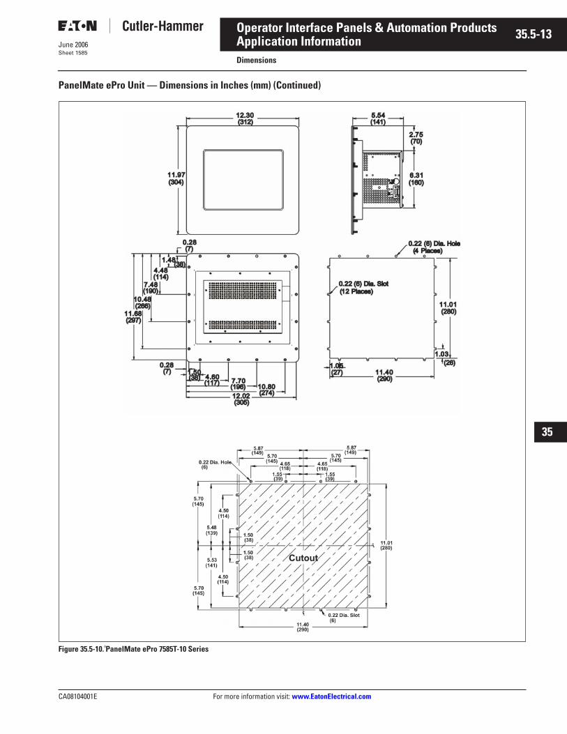
CA08104001E For more information visit: www.EatonElectrical.com
35.5-13June 2006
Operator Interface Panels & Automation Products
22
23
24
25
26
27
28
29
30
31
32
33
34
35
36
37
38
39
40
41
42
43
Application InformationDimensions
Sheet 1585
PanelMate ePro Unit — Dimensions in Inches (mm) (Continued)
Figure 35.5-10. PanelMate ePro 7585T-10 Series
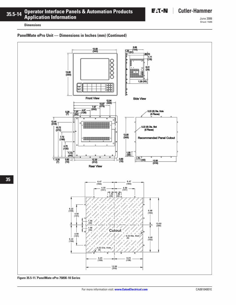
35.5-14
For more information visit: www.EatonElectrical.com CA08104001E
June 2006
Operator Interface Panels & Automation Products
22
23
24
25
26
27
28
29
30
31
32
33
34
35
36
37
38
39
40
41
42
43
Application InformationDimensions
Sheet 1586
PanelMate ePro Unit — Dimensions in Inches (mm) (Continued)
Figure 35.5-11. PanelMate ePro 7585K-10 Series
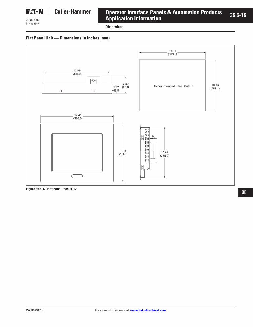
CA08104001E For more information visit: www.EatonElectrical.com
35.5-15June 2006
Operator Interface Panels & Automation Products
22
23
24
25
26
27
28
29
30
31
32
33
34
35
36
37
38
39
40
41
42
43
Application InformationDimensions
Sheet 1587
Flat Panel Unit — Dimensions in Inches (mm)
Figure 35.5-12. Flat Panel 7585DT-12
12.99 (330.0)
10.04(255.0)
3.37(85.6)1.92
(48.8)
11.46(291.1)
14.41(366.0)
13.11(333.0)
10.16(258.1)
Recommended Panel Cutout
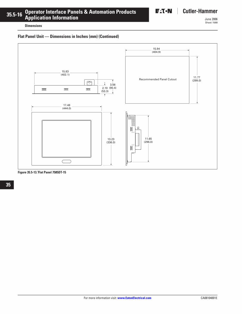
35.5-16
For more information visit: www.EatonElectrical.com CA08104001E
June 2006
Operator Interface Panels & Automation Products
22
23
24
25
26
27
28
29
30
31
32
33
34
35
36
37
38
39
40
41
42
43
Application InformationDimensions
Sheet 1588
Flat Panel Unit — Dimensions in Inches (mm) (Continued)
Figure 35.5-13. Flat Panel 7585DT-15
15.83 (402.1)
17.48 (444.0)
13.23 (336.0)
11.65 (296.0)
3.56 (90.4)2.10
(53.3)
Recommended Panel Cutout
15.94 (404.9)
11.77 (299.0)
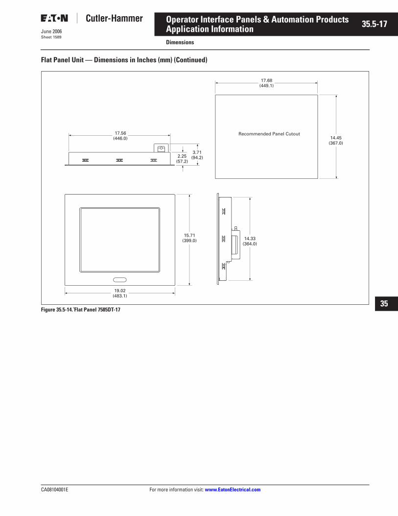
CA08104001E For more information visit: www.EatonElectrical.com
35.5-17June 2006
Operator Interface Panels & Automation Products
22
23
24
25
26
27
28
29
30
31
32
33
34
35
36
37
38
39
40
41
42
43
Application InformationDimensions
Sheet 1589
Flat Panel Unit — Dimensions in Inches (mm) (Continued)
Figure 35.5-14. Flat Panel 7585DT-17
14.33 (364.0)
2.25 3.71
(94.2)
17.56 (446.0)
19.02 (483.1)
15.71 (399.0)
17.68 (449.1)
14.45 (367.0)
Recommended Panel Cutout
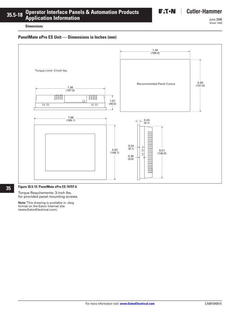
35.5-18
For more information visit: www.EatonElectrical.com CA08104001E
June 2006
Operator Interface Panels & Automation Products
22
23
24
25
26
27
28
29
30
31
32
33
34
35
36
37
38
39
40
41
42
43
Application InformationDimensions
Sheet 1590
PanelMate ePro ES Unit — Dimensions in Inches (mm)
Figure 35.5-15. PanelMate ePro ES 7475T-6
Torque Requirements: 3-inch lbs. for provided panel mounting screws.
Note: This drawing is available in .dwg format on the Eaton Internet site (www.EatonElectrical.com).
7.40(188.0)
Recommended Panel Cutout
5.51(140.0)
0.24(6.1)
7.36 (187.0)
7.68(195.1)
1.57(40.0)
5.83(148.1)
0.39(9.9)
0.24(6.1)
5.55(141.0)
Torque Limit: 3-Inch lbs.
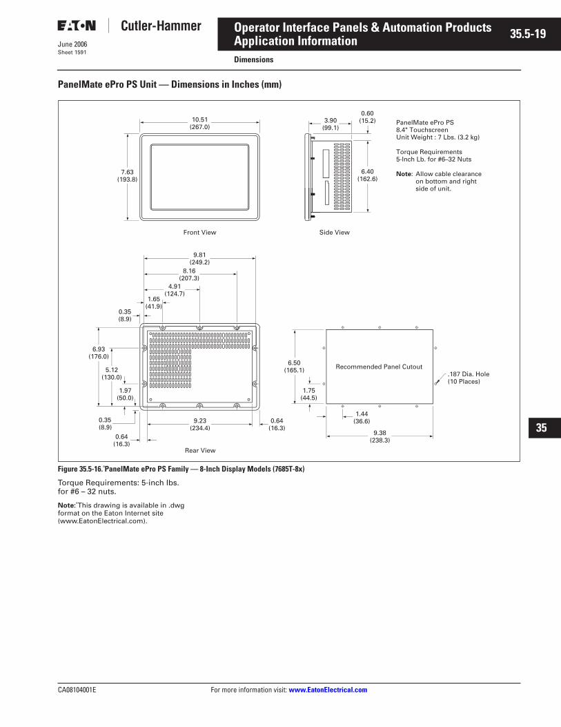
CA08104001E For more information visit: www.EatonElectrical.com
35.5-19June 2006
Operator Interface Panels & Automation Products
22
23
24
25
26
27
28
29
30
31
32
33
34
35
36
37
38
39
40
41
42
43
Application InformationDimensions
Sheet 1591
PanelMate ePro PS Unit — Dimensions in Inches (mm)
Figure 35.5-16. PanelMate ePro PS Family — 8-Inch Display Models (7685T-8x)
Torque Requirements: 5-inch lbs. for #6 – 32 nuts.
Note: This drawing is available in .dwg format on the Eaton Internet site (www.EatonElectrical.com).
Side View
Recommended Panel Cutout
Front View
Rear View
9.38(238.3)
9.23(234.4)
5.12(130.0)
0.64(16.3)
0.35(8.9)
1.97(50.0)
6.93(176.0)
1.65(41.9)
0.35(8.9)
4.91(124.7)
8.16(207.3)
0.64 (16.3)
1.44(36.6)
1.75(44.5)
9.81(249.2)
6.50(165.1)
10.51(267.0)
7.63(193.8)
3.90(99.1)
.187 Dia. Hole(10 Places)
6.40(162.6)
0.60(15.2) PanelMate ePro PS
8.4" TouchscreenUnit Weight : 7 Lbs. (3.2 kg)
Torque Requirements5-Inch Lb. for #6–32 Nuts
Note: Allow cable clearance on bottom and right side of unit.
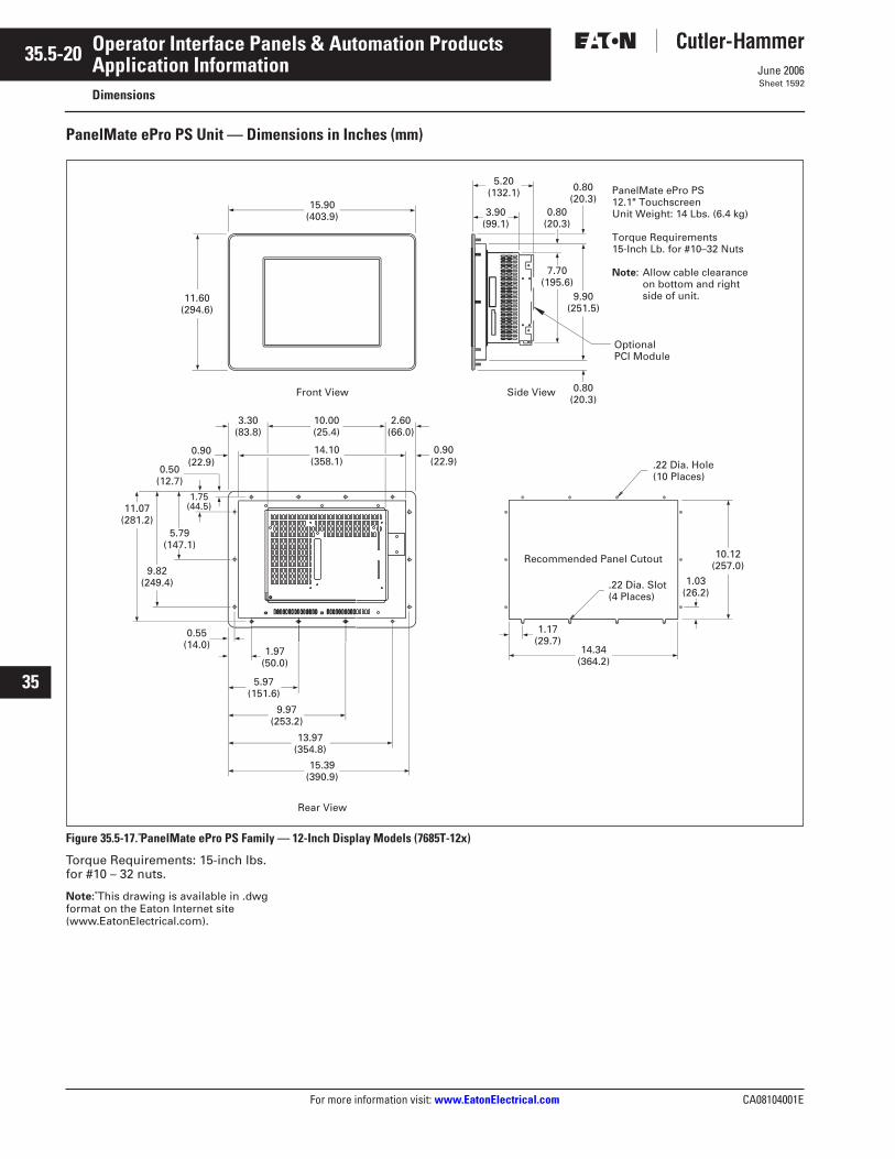
35.5-20
For more information visit: www.EatonElectrical.com CA08104001E
June 2006
Operator Interface Panels & Automation Products
22
23
24
25
26
27
28
29
30
31
32
33
34
35
36
37
38
39
40
41
42
43
Application InformationDimensions
Sheet 1592
PanelMate ePro PS Unit — Dimensions in Inches (mm)
Figure 35.5-17. PanelMate ePro PS Family — 12-Inch Display Models (7685T-12x)
Torque Requirements: 15-inch lbs. for #10 – 32 nuts.
Note: This drawing is available in .dwg format on the Eaton Internet site (www.EatonElectrical.com).
Side View
Recommended Panel Cutout
Front View
Rear View
5.79 (147.1)
1.97 (50.0)
14.34 (364.2)
5.97 (151.6)
0.55 (14.0)
11.07 (281.2)
9.82 (249.4)
1.75 (44.5)
0.50 (12.7)
9.97 (253.2)
13.97 (354.8)
1.17 (29.7)
.22 Dia. Slot (4 Places)
11.60(294.6)
15.90(403.9) 3.90
(99.1)
5.20(132.1)
1.03 (26.2)
.22 Dia. Hole (10 Places)
10.12 (257.0)
PanelMate ePro PS12.1" TouchscreenUnit Weight: 14 Lbs. (6.4 kg)
Torque Requirements15-Inch Lb. for #10–32 Nuts
Note: Allow cable clearanceon bottom and right side of unit.
OptionalPCI Module
9.90 (251.5)
0.80(20.3)
15.39 (390.9)
7.70 (195.6)
0.80(20.3)
0.80(20.3)
10.00 (25.4)
3.30 (83.8)
2.60 (66.0)
14.10 (358.1)
0.90 (22.9)
0.90 (22.9)
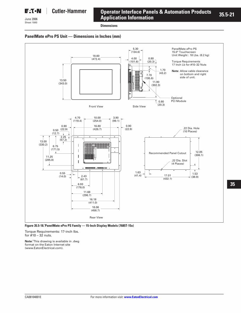
CA08104001E For more information visit: www.EatonElectrical.com
35.5-21June 2006
Operator Interface Panels & Automation Products
22
23
24
25
26
27
28
29
30
31
32
33
34
35
36
37
38
39
40
41
42
43
Application InformationDimensions
Sheet 1593
PanelMate ePro PS Unit — Dimensions in Inches (mm)
Figure 35.5-18. PanelMate ePro PS Family — 15-Inch Display Models (7685T-15x)
Torque Requirements: 17-inch lbs. for #10 – 32 nuts.
Note: This drawing is available in .dwg format on the Eaton Internet site (www.EatonElectrical.com).
Side View
Recommended Panel Cutout
Rear View
Front View
4.00 (101.6)
1.63 (41.4)
0.55 (14.0) 2.43
(61.7)
6.93 (176.0)
13.00 (330.2) 6.75
(171.5)
11.25 (285.8)
2.25 (57.2)
0.50 (12.7)
11.68 (296.7)
16.18 (411.0)
18.06 (458.7)
13.50 (343.0)
18.60 (472.4)
5.30 (134.6)
17.01 (432.1)
.22 Dia. Hole (10 Places)
.22 Dia. Slot (4 Places)
1.53 (38.9)
12.05 (306.1)
Optional PCI Module0.80
(20.3)
11.90 (302.3)
0.80 (20.3)
7.70 (195.6)
1.70 (43.2)
10.00 (254.0)
4.70 (119.4)
3.90 (99.1)
0.90 (22.9)
16.80 (426.7)
0.90 (22.9)
PanelMate ePro PS15.0" Touchscreen Unit Weight : 18 Lbs. (8.2 kg)
Torque Requirements17 Inch Lb for #10–32 Nuts
Note: on bottom and right side of unit.
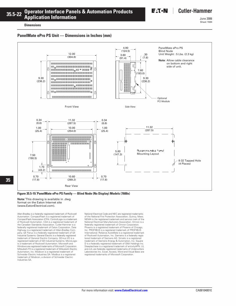
35.5-22
For more information visit: www.EatonElectrical.com CA08104001E
June 2006
Operator Interface Panels & Automation Products
22
23
24
25
26
27
28
29
30
31
32
33
34
35
36
37
38
39
40
41
42
43
Application InformationDimensions
Sheet 1594
PanelMate ePro PS Unit — Dimensions in Inches (mm)
Figure 35.5-19. PanelMate ePro PS Family — Blind Node (No Display) Models (7600x)
Note: This drawing is available in .dwg format on the Eaton Internet site (www.EatonElectrical.com).
Allen-Bradley is a federally registered trademark of Rockwell Automation. CompactFlash is a registered trademark of CompactFlash Association (CFA). ControlLogix is a trademark of Rockwell Automation. CSA is a registered trademark of the Canadian Standards Association. Cutler-Hammer is a federally registered trademark of Eaton Corporation. Data Highway is a registered trademark of Allen-Bradley Com-pany. GE Fanuc is a federally registered trademark of GE Industrial Systems. General Electric is a federally registered trademark of General Electric Company. GEnius I/O is a registered trademark of GE Industrial Systems. MicroLogix is a trademark of Rockwell Automation. Microsoft and Windows are registered trademarks of Microsoft Corporation. Mitsubishi FX is a registered trademark of Mitsubishi Electric Automation, Inc. Modicon is a registered trademark of Schneider Electric Industries SA. Modbus is a registered trademark of Modicon, a division of Schneider Electric Industries SA.
National Electrical Code and NEC are registered trademarks of the National Fire Protection Association, Quincy, Mass. NEMA is the registered trademark and service mark of the National Electrical Manufacturers Association. Omron is a federally registered trademark of Omron Corporation. Phoenix is a registered trademark of Phoenix of Chicago, Inc. PROFIBUS is a registered trademark of PROFIBUS International. Reliance AutoMate is a registered trademark of Rockwell Automation, Inc. Siemens is a federally regis-tered trademark of Siemens AG. Simatic is a registered trademark of Siemens Energy & Automation, Inc. Square D is a federally registered trademark of SNA Holdings Inc. Steeplechase is a registered trademark of entivityAPN. UL and cUL are federally registered trademarks of Underwriters Laboratories Inc. Excel, Access, Word and Visual Basic are registered trademarks of Microsoft Corporation.
Recommended PanelMounting Layout
Side View
Rear View
Front View
11.32 (287.5)
10.60 (269.2)
0.70 (17.8)
1.70 (43.2)
7.50 (190.5)
0.34 (8.6)
0.70 (17.8)
0.34 (8.6)
5.80 (147.3)
12.00 (304.8)
9.30 (236.2)
3.60 (91.4)
8-32 Tapped Hole (4 Places)
11.32 (287.5)
9.30 (236.2)
4.90 (124.5)
7.60 (193.0)
.30 (7.6)
10.00 (254.0)
1.00 (25.4)
1.00 (25.4)
Optional PCI Module
PanelMate ePro PSBlind Node Unit Weight : 5 Lbs. (2.3 kg)
Note: Allow cable clearance on bottom and right side of unit.