eaton duraforce™ hpr conversion procedurespub/@eaton/@hyd/documents/c… · eaton duraforce hpr...
TRANSCRIPT

Eaton® DuraForce™ HPR Conversion Procedures

2 EATON Duraforce HPR Conversion Procedures Manual E-PUPI-TM019-E July 2012
Content Page #
Table of Contents
Tools Required 2
Introduction 3
Model Code 4
Exchanging Pressure Compensator Springs
Set Up and Procedure 6
Externally Disabling the Load Sense
Set Up and Procedure 7
Exchanging Control types LP, E1L and H1L
Set Up and Procedure
Exchanging the Horsepower Spring – with TL2 or ETP Controls 9
Set Up and Procedure
Activating the Z1 and Z2 Ports on HPR Pumps with TL2 or ETP Controls
Set Up and Procedure 11
Exchanging Solenoids on E1L Controls 13
Set Up and Procedure
Installing a PTO Kit Directly (without Auxiliary Pump)
Set Up and Procedure 14
Torque Chart 17
Maximum Displacement Adjustment – Single HPR Pumps
Set Up and Procedure 18
Minimum Displacement Adjustment – Single HPR Pumps
Set Up and Procedure 19
Operational Parameters 20
Part Numbers Listing 22
Tools Required
Exchanging Pressure Compensator Springs
• 5mm Allen wrench
• New pressure compensator spring
• Torque wrench capable of setting 14 N-m (10 ft-lb)
Externally Disabling the Load Sense
• 6mm wrench
• 13mm wrench
• One M14 metal plug (Refer to Customer Connect for correct part number)
Exchanging Control Types LP, E1L & H1L
• 6mm Allen wrench
• Torque wrench capable of setting 23 N-m (17 ft-lb)
Exchanging the Horsepower Spring - with TL2 or ETP Controls
• 6mm Allen wrench
• 21mm wrench
• Torque wrench capable of 45 ft-lb (61 N-m).
Activating the Z1 and Z2 Ports with TL2 or ETP Controls
• 2mm Allen wrench
• 6mm Allen wrench
• Torque wrench capable of 23 N-m (17 ft-lb).
Exchanging Solenoids on E1L Controls
• 3mm Allen wrench
• Torque wrench capable of setting 2.7 N-m (2.0 ft-lb)
Installing a PTO Kit onto HPR Pump Directly (W/O Auxiliary Pump)
• Metric Wrench (various sizes depending on the unit size)
• Allen wrench (various sizes depending on the unit size)
• Grease or petroleum jelly (optional)
• PTO Kit
Maximum & Minimum Displacement Adjustments
• 6mm Allen wrench
• 19mm closed-end wrench
Activating the Z1 and Z2 Ports on HPR Pumps with TL2 or ETP ControlsSet-up and Procedure

3EATON Duraforce HPR Conversion Procedures Manual E-PUPI-TM019-E July 2012
This manual will provide you with information and procedures for general conversions of Eaton® DuraForce™ HPR Self-Regulating Pump for Open Loop Operations. Procedures outlined in this manual will allow you to be more flexible with your inventory and better service your customers. To ensure accuracy of conversion and prevent part loss or damage, certain components or subassemblies are disassembled, inspected, and reassembled when removed from the pump.
Training
You have been provided information on the conversion of DuraForce products. Proper application of the information requires specific training and may require use of specialized tooling and equipment. All requests for training must be coordinated through your Eaton Account Manager. He can also provide you price and availability of any specialized tooling. If you choose to proceed with the conversion of the DuraForce products absent the necessary training and/or these specialized tools, you do so at your risk.
Eaton will accept no claim for warranty resulting from deficiencies in the conversion. Please refer to the Eaton literature web site for warranty information at www.eaton.com/hydraulics/warranty.
Labeling Converted Units
All units that have been converted must retain the original Eaton label and have a second Eaton label placed on the unit. This second label at a minimum must state
Converted Eaton Model Code # (Final Eaton model code of the converted unit)
Conversion done by (Name of your company)
Conversion Parts
All requests for specific conversion part information should be addressed to your Eaton account representative. Additional information can be found through your Eaton customer connect portal. All requests or inquiries must be accompanied by the complete model and serial number of the base unit you want to convert.
Cleanliness
Cleanliness is extremely important when repairing a hydrostatic pump or motor. Before disconnecting the lines, clean foreign material from exterior of unit. Work in a clean area. Clean all metal parts in clean solvent. Blow parts dry with air. Don’t wipe parts with cloth or paper towel, because lint or other matter could cause damage. Check all mating surfaces. Replace any parts that have scratches or burrs that could cause leakage. Don’t use coarse grit paper, files or grinders on parts.
Environmental Concerns
Protection of the natural fundamentals of life is one of our predominant tasks. We are continuously improving the protection of the environment as far as applications are concerned. We encourage you to contribute your share to comply with this demand. In connection with work to be performed, the environmental regulations of the machine manufacturer must be respected.
In general:
• Greases and oils which cannot be used any more have to be collected. They are normally a threat to water reserves and must be kept away from the environment.
• Adhere to national and local regulations for waste disposal.
Seals
A good conversion policy is to replace all old seals with new seals whenever units are disassembled. This avoids potential damage during seal removal. Lubricate seals with petroleum jelly. Use only clean and recommended oil when assembling unit. Information on recommended filters and fluids can be found in the Operational Parameters section.
Torque
All torque specifications are for lubricated threads. Bolts for gasketed surfaces should be checked for proper torque.
Introduction
4 EATON Duraforce HPR Conversion Procedures Manual E-PUPI-TM019-E July 2012
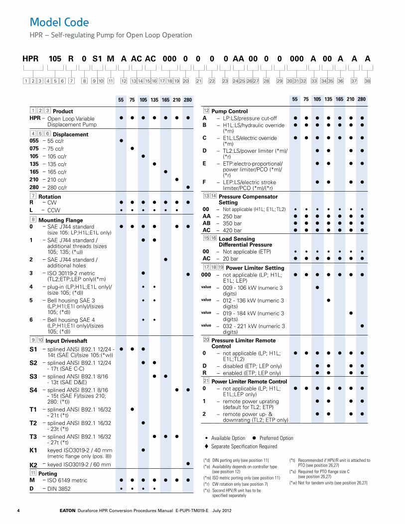
1 2 3 ProductHPR – Open Loop Variable
Displacement Pumpl l l l l l l
4 5 6 Displacement055 – 55 cc/r l075 – 75 cc/r l105 – 105 cc/r l135 – 135 cc/r l165 – 165 cc/r l210 – 210 cc/r l280 – 280 cc/r l
7 RotationR – CW l l l l l l lL – CCW • • • • • •
8 Mounting Flange0 – SAE J744 standard
(size 105: LP;H1L;E1L only)l l l l l l
1 – SAE J744 standard / additional threads (sizes 105; 135; (*u))
l l
2 – SAE J744 standard / additional holes
l
3 – ISO 30119-2 metric (TL2;ETP;LEP only)(*m)
l l
4 – plug-in (LP;H1L;E1L only)/(size 105; (*d))
• •
5 – Bell housing SAE 3 (LP;H1l;E1l only)/(sizes 105; (*d))
• •
6 – Bell housing SAE 4 (LP;H1l;E1l only)/(sizes 105; (*d))
• •
9 10 Input Driveshaft
S1 – splined ANSI B92.1 12/24 - 14t (SAE C)/(size 105:(*w))
l l l
S2 – splined ANSI B92.1 12/24 - 17t (SAE C-C)
l l
S3 – splined ANSI B92.1 8/16 - 13t (SAE D&E)
l l
S4 – splined ANSI B92.1 8/16 - 15t (SAE F)/(sizes 210; 280: (*t))
l l
T1 – splined ANSI B92.1 16/32 - 21t (*t)
l
T2 – splined ANSI B92.1 16/32 - 23t (*t)
l
T3 – splined ANSI B92.1 16/32 - 27t (*t)
l l l
K1 keyed ISO3019-2 / 40 mm (metric flange only (pos. 8))
l
K2 keyed ISO3019-2 / 60 mm– l
11 PortingM – ISO 6149 metric l l l l l l l
D – DIN 3852 • • • •
12 Pump ControlA – LP:LS/pressure cut-off l l l l l l lB – H1L:LS/hydraulic override
(*m)l l l l l l l
C – E1L:LS/electric override (*m)
l l l l l l l
D – TL2:LS/power limiter (*m)/(*r)
l l l l
E – ETP:electro-proportional/power limiter/PCO (*m)/(*r)
l l l l
F – LEP:LS/electric stroke limiter/PCO (*m)/(*r)
l l l l
13 14 Pressure Compensator Setting
00 – Not applicable (H1L; E1L; TL2) • • • • • • •AA – 250 bar l l l l l l lAB – 350 bar l l l l l l lAC – 420 bar l l l l l l l15 16 Load Sensing
Differential Pressure00 – Not applicable (ETP) • • • • • • •AC – 20 bar l l l l l l l
17 18 19 Power Limiter Setting000 – not applicable (LP; H1L;
E1L; LEP)l l l l l l l
value – 009 - 106 kW (numeric 3 digits)
l
value – 012 - 136 kW (numeric 3 digits)
l
value – 019 - 184 kW (numeric 3 digits)
l
value – 032 - 221 kW (numeric 3 digits)
l
20 Pressure Limiter Remote Control
0 – not applicable (LP; H1L; E1L;TL2)
l l l l l l l
D – disabled (ETP; LEP only) l l l lR – enabled (ETP; LEP only) l l l l21 Power Limiter Remote Control0 – not applicable (LP; H1L;
E1L;LEP only)l l l l l l l
1 – remote power uprating (default for TL2; ETP)
l l l l
2 – remote power up- & downrating (TL2; ETP only)
l l l l
55 75 105 135 165 210 280 55 75 105 135 165 210 280
Model CodeHPR – Self-regulating Pump for Open Loop Operation
HPR 105 R 0 S1 M A AC AC 000 0 0 0 0 AA 00 0 0 000 A 00 A A A
34 351 2 3 30 31 324 5 6 17 18 1911 20 22 3723 3828 298 12 21 36337 24 25 26 279 10 13 14 15 16
• Available Option l Preferred Option t Separate Specification Required
(*d) DIN porting only (see position 11)(*e) Availability depends on controller type
(see position 12)(*m) ISO metric porting only (see position 11)(*r) CW rotation only (see position 7)(*s) Second HPV/R unit has to be
specified separately
(*t) Recommended if HPV/R unit is attached to PTO (see position 26,27)
(*u) Required for PTO flange size C (see position 26,27)
(*w) Not for tandem units (see position 26,27)

5EATON Duraforce HPR Conversion Procedures Manual E-PUPI-TM019-E July 2012
22 Control Solenoids0 – not applicable (LP; H1L; TL2) l l l l l l lA – AMP / 12V l l l l l l lB – AMP / 24 V l l l l l l lC – DIN / 12 V • • • • • • •D – DIN / 24 V • • • • • • •E – Deutsch / 12V • • • • • • •F – Deutsch / 24V • • • • • • •23 Noise Optimization Devices0 – No Noise Reduction Device l l l • • •1 – With SPU primary noise
reduction (sizes 55-105: (*r))l l l l l l l
24 25 Auxiliary Pad and Shaft Definition
0G – to add gear pump see positions 26,27
• • • • • • •
AA – SAE J744 A without shaft coupling (default)
l l l l l l l
AB – SAE J744 A / ANSI B92.1 16/32-9 teeth (A)
l l l l l l
AC – SAE J744 A / ANSI B92.1 16/32 - 11 teeth
• •
AD – SAE J744 A / ANSI B92.1 16/32 - 13 teeth
• • • •
AE – SAE J744 B without shaft coupling
• • • • • • •
AF – SAE J744 B / ANSI B92.1 16/32-13 teeth (B)
• • • • • • •
AG – SAE J744 B / ANSI B92.1 16/32-15 teeth (B-B)
• • • • •
AH – SAE J744 C without shaft coupling
• • • • • • •
AJ – SAE J744 C / ANSI B92.1 12/24-14 teeth (C)
• • • • • • •
AK – SAE J744 C / ANSI B92.1 16/32 - 21 teeth
• • • •
AL – SAE J744 C / ANSI B92.1 16/32 - 23 teeth
• • • •
AM – SAE J744 D without shaft coupling
• • • •
AN – SAE J744 D / ANSI B92.1 8/16-13 teeth (D)
•
AP – SAE J744 D / ANSI B92.1 12/24 - 17 teeth
•
AQ – SAE J744 D / ANSI B92.1 16/32 - 27 teeth
• • •
AR – SAE J744 E without shaft coupling
• •
AS – SAE J744 E / ANSI B92.1 16/32 - 27 teeth
•
26 27 Auxiliary Pump or Tandem Adapter
00 – without l l l l l l lBA – internal gear pump 16cc l l • •BB – internal gear pump 22,5cc • • l lBC – internal gear pump tandem
16+16cc• • • •
BD – internal gear pump tandem 16+22,5cc
• • • •
BE – internal gear pump tandem 22,5+16cc
• • • •
BF – internal gear pump tandem 22,5+22,5cc
• • • •
BG – external gear pump 31cc (*r) • •BH – external gear pump 38cc • • • •BJ – external gear pump 44cc (*r) • •BK – external gear pump tandem
22,5+22,5 cc (*r)• • • •
BL – HPV/R 55 mounting preparation (*s)
• • • • • • •
BM – HPV/R 75 mounting preparation (*s)
• • • • • •
BN – HPV/R 105 mounting preparation (*s)
• • • • •
BP – HPV/R 135 mounting preparation (*s)
• • •
BQ – HPV/R 210 mounting preparation (*s)
• •
28 Auxiliary Drive on Internal Gear Pump
0 – Without internal gear pump l l l l l l l
A – SAE J744 A / ANSI B92.1 16/32 - 9 teeth (A) (default)
l l l l
B – SAE J744 B without shaft coupling
• • • •
C – SAE J744 B/ANSI B92.1 16/32 - 13 teeth (B)
• • • •
D – SAE J744 B/ANSI B92.1 16/32 - 15 teeth (B-B)
• • • •
E – SAE J744 C without shaft coupling
• •
F – SAE J744 C/ANSI B92.1 12/24 - 14 teeth (C)
• •
29 Internal Gear Pump Supply0 – Without internal gear pump l l l l l l lE – External supply port l l l l
30 31 32 Maximum Displacement Setting
000 – Catalog Pump Rating l l l l l l l
33 Operating SpeedA – Catalog Pump Rating l l l l l l l
34 35 Special Requirements00 – Without special
requirements (default)l l l l l l l
36 Surface Coating0 – Anti rust conservation oil
(default)l l l l l l l
A – Primer blue l l l l l l l
37 Unit IdentificationA – Eaton l l l l l l l
38 Type Code ReleaseA – Revision Level A l l l l l l l
55 75 105 135 165 210 280 55 75 105 135 165 210 280
Model CodeHPR – Self-regulating Pump for Open Loop Operation
HPR 105 R 0 S1 M A AC AC 000 0 0 0 0 AA 00 0 0 000 A 00 A A A
34 351 2 3 30 31 324 5 6 17 18 1911 20 22 3723 3828 298 12 21 36337 24 25 26 279 10 13 14 15 16
• Available Option l Preferred Option t Separate Specification Required

6 EATON Duraforce HPR Conversion Procedures Manual E-PUPI-TM019-E July 2012
Procedure to Exchange Pressure Compensator Springs
Remove the four socket head cap screws (S.H.C.S) from the Side Cover with the 5mm Allen wrench. Keep them for reuse.
Remove the Side Cover from the pump control. Make sure not to lose or damage the two o-rings between the Side Cover and the pump control. Keep the two o-rings for reuse.
Remove the Spring Hat from the Pressure Compensator Spring. Keep for reuse.
Remove the existing Pressure Compensator Spring from the pump control.
Install the new Pressure Compensator Spring into the pump control. See table above for available springs.
Reinstall the Spring Hat from step #3.
Prior to reinstalling the Side Cover, make sure that the two o-rings are in good condition (i.e. not damaged) and are properly positioned in the o-ring grooves.
Reinstall the Side Cover onto the pump control. Secure the Side Cover with the four S.H.C.S.removed in step #1.
Note: Since the Pressure Compensator Spring pre-loads the Side Cover, you will have to compress the spring in order to get the threads of the first S.H.C.S. started. To do this, you will have to push in the Side Cover to compress the spring. For the higher pressure rated springs, the assistance of a second person or a clamping device may be required.
Tighten each S.H.C.S. with the 5mm Allen wrench and torque each one to 14 N-m (10 ft-lb).
Restamp the pump control with the new Control Part Number to reflect the correct spring. Refer to Eaton for a listing of control part numbers.
Exchanging Pressure Compensator SpringsSet-up and Procedure
Important
Care should be taken when removing the last S.H.C.S. The Side Cover is spring-loaded by the Pressure Compensator Spring and it may spring-out at you when the last S.H.C.S. is removed.
1
2
7
3
8
4
95
106
Pressure Compensator Spring Pressure Spring Free Spring WirePart Number Range, bar Length, mm Diameter, mm
000 921 2428 125-230 35.4 2.4
000 921 2447 230-350 40.0 2.4
000 921 2551 350-420 45.1 2.5
7EATON Duraforce HPR Conversion Procedures Manual E-PUPI-TM019-E July 2012
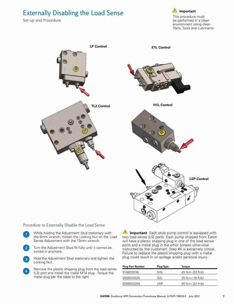
Procedure to Externally Disable the Load Sense
While holding the Adjustment Stud stationary with the 6mm wrench, loosen the Locking Nut on the Load Sense Adjustment with the 13mm wrench.
Turn the Adjustment Stud IN fully until it cannot be turned in anymore.
Hold the Adjustment Stud stationary and tighten the Locking Nut.
Remove the plastic shipping plug from the load sense (LS) port and install the metal M14 plug. Torque the metal plug per the table to the right.
Important Each style pump control is equipped with two load sense (LS) ports. Each pump shipped from Eaton will have a plastic shipping plug in one of the load sense ports and a metal plug in the other (unless otherwise instructed by the customer). Step #4 is extremely critical. Failure to replace the plastic shipping plug with a metal plug could result in oil spillage and/or personal injury.
Externally Disabling the Load SenseSet-up and Procedure
1
2
3
4
Important
This procedure must be performed in a clean environment using clean Parts, Tools and Lubricants
H1L ControlTL2 Control
E1L ControlLP Control
LEP Control
Plug Part Number Plug Type Torque
9148010156 DIN 45 N-m (33 ft-lb)
0009524020 ISO 25 N-m (18 ft-lb)
0009033200 UNF 30 N-m (22 ft-lb)

8 EATON Duraforce HPR Conversion Procedures Manual E-PUPI-TM019-E July 2012
Procedure to Exchange Pump Controls
Remove the three S.H.C.S. with the 6mm Allen wrench and keep them for reuse.
Remove the existing control from the pump. Make sure to remove all O-Rings along with the existing control.
Make sure that all the O-Rings are in good condition (i.e. undamaged) and are properly placed in the o-ring grooves on the new control.
Align the passages in the new pump control with those on the pump rear head, then install the new control onto the pump and fasten it with the three S.H.C.S. from step #1.
Tighten the S.H.C.S. with the 6mm Allen wrench and torque each one to 23 N-m (17 ft-lb).
1
2
3
4
5
Exchanging Control Types LP, E1L and H1LSet-up and Procedure
Important
This procedure is for control types LP, E1L and H1L only.
A LP control type
Load Sense/PressureCompensator Control
S.H.C.S. (3 Places)
O-Ring (3 Places)
9EATON Duraforce HPR Conversion Procedures Manual E-PUPI-TM019-E July 2012
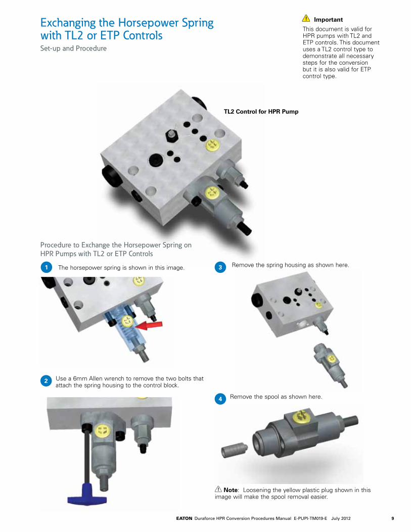
Exchanging the Horsepower Spring with TL2 or ETP ControlsSet-up and Procedure
Important
This document is valid for HPR pumps with TL2 and ETP controls. This document uses a TL2 control type to demonstrate all necessary steps for the conversion but it is also valid for ETP control type.
Procedure to Exchange the Horsepower Spring on HPR Pumps with TL2 or ETP Controls
The horsepower spring is shown in this image.1 Remove the spring housing as shown here.
Remove the spool as shown here.
Note: Loosening the yellow plastic plug shown in this image will make the spool removal easier.
Use a 6mm Allen wrench to remove the two bolts that attach the spring housing to the control block.
3
4
2
TL2 Control for HPR Pump

10 EATON Duraforce HPR Conversion Procedures Manual E-PUPI-TM019-E July 2012
7
8
9
10
11
65 Use a 21mm wrench to loosen the lock nut as shown here.
Replace the spring with the new one.
Place the new spring between the two spring hats as shown here.
Install the spring hats, spring and the lock nut back into the spring housing.
Hand tight the lock nut to keep it in position.
Torque the lock nut to 45 ft-lb (61 Nm).
Once the lock nut is loose, remove the spring and the two spring hats as shown here.
Exchanging the Horsepower Spring with TL2 or ETP Controls Procedure Continued
Important
Pay attention to the o-ring between the spring housing and the control block. Make sure that it is installed correctly.
12 13
14
Install the spring housing back on the control block.
Use the existing bolts to secure the spring housing and Torque them to 17ft-lb (23 N-m).
Important
At the end of this procedure, this unit must be functionally tested to insure the proper horsepower setting.
Install the spool back into the spring housing as shown here. Please note the spool orientation

11EATON Duraforce HPR Conversion Procedures Manual E-PUPI-TM019-E July 2012
Activating the Z1 and Z2 Ports on HPR Pumps with TL2 or ETP ControlsSet-up and Procedure
Important
This document was created using an HPR pump with TL2 control; it is also valid for HPR pumps with ETP controls.
For a better view, some of the images in this document show the pump control only. It is not necessary to remove the control from the pump in order to complete this procedure.
This procedure must be performed in a clean environment using clean Parts, Tools and Lubricants.
Procedure to Install the Internal Plug to Enable Z2 Function
Remove the horsepower adjustment assembly as shown here.
Remove the two bolt holding the horsepower adjustment assembly as shown here.
2
1
External Connection Operating State Z1 Port Z2 Port Internal Plug between Z1 and Z2
Z1 and Z2 are Externally connected Externally connected No Plug An External connection disabled to Z2 to Z1 between Z1 & Z2 is required
Only Z1 is enabled Controlling pressure Metal Plug No Plug No External connection is required required
Only Z2 is enabled Must be connected Controlling pressure Internal plug must No External connection to tank is required be installed required
Both Z1 and Z2 Controlling Pressure Controlling Pressure Internal Plug must No external connection are enabled is required is required be installed required
The following chart shows necessary steps and changes required for different states of operation with the Mechanical Horsepower control:
Inspect the o-ring on the horsepower adjustment assembly, replace it if necessary.
3
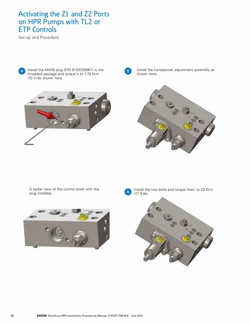
12 EATON Duraforce HPR Conversion Procedures Manual E-PUPI-TM019-E July 2012
54 Install the M4X6 plug (P/N 9133339061) in the threaded passage and torque it to 1.70 N-m (15 in-lb) shown here.
Install the horsepower adjustment assembly as shown here.
Activating the Z1 and Z2 Ports on HPR Pumps with TL2 or ETP ControlsSet-up and Procedure
6Install the two bolts and torque them to 23 N-m (17 ft-lb).
A better view of the control block with the plug installed.

13EATON Duraforce HPR Conversion Procedures Manual E-PUPI-TM019-E July 2012
Exchanging Solenoids on E1L Controls Set-up and Procedure
Procedure to Exchange Solenoids
Remove the four S.H.C.S. from the Proportional Solenoid with the 3mm Allen wrench. Keep the four S.H.C.S. with the existing solenoid as an assembly.
Remove the existing Solenoid O-Ring and keep it with the existing solenoid as an assembly.
Make sure that the new Solenoid O-Ring is in good condition (i.e. undamaged) and is properly placed in the o-ring groove on the new solenoid.
Install the new Proportional Solenoid onto the pump control and fasten it with the four new S.H.C.S. that came with the new solenoid.
Tighten the S.H.C.S. with the 3mm Allen wrench and torque each one to 2.7 N-m (2.0 ft-lb).
1
2
3
4
5
14 EATON Duraforce HPR Conversion Procedures Manual E-PUPI-TM019-E July 2012
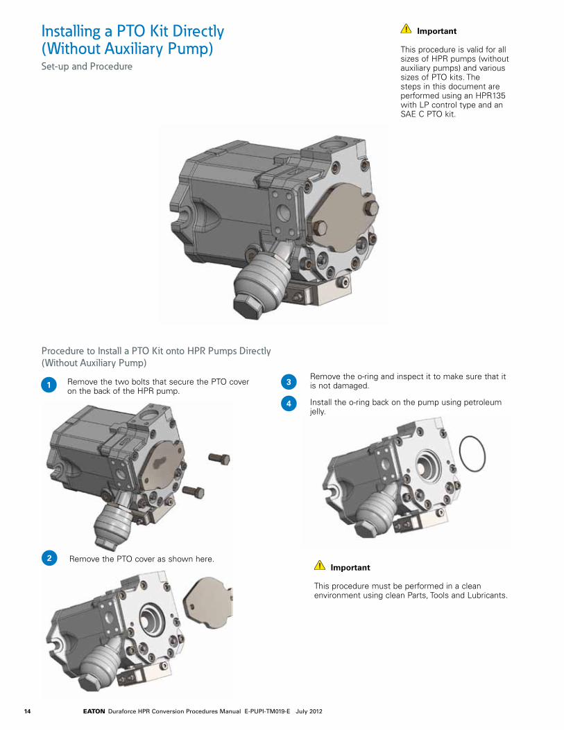
Installing a PTO Kit Directly (Without Auxiliary Pump)Set-up and Procedure
1
Important
This procedure must be performed in a clean environment using clean Parts, Tools and Lubricants.
Important
This procedure is valid for all sizes of HPR pumps (without auxiliary pumps) and various sizes of PTO kits. The steps in this document are performed using an HPR135 with LP control type and an SAE C PTO kit.
Procedure to Install a PTO Kit onto HPR Pumps Directly (Without Auxiliary Pump)
Remove the two bolts that secure the PTO cover on the back of the HPR pump.
Remove the PTO cover as shown here.2
3
4
Remove the o-ring and inspect it to make sure that it is not damaged.
Install the o-ring back on the pump using petroleum jelly.
15EATON Duraforce HPR Conversion Procedures Manual E-PUPI-TM019-E July 2012
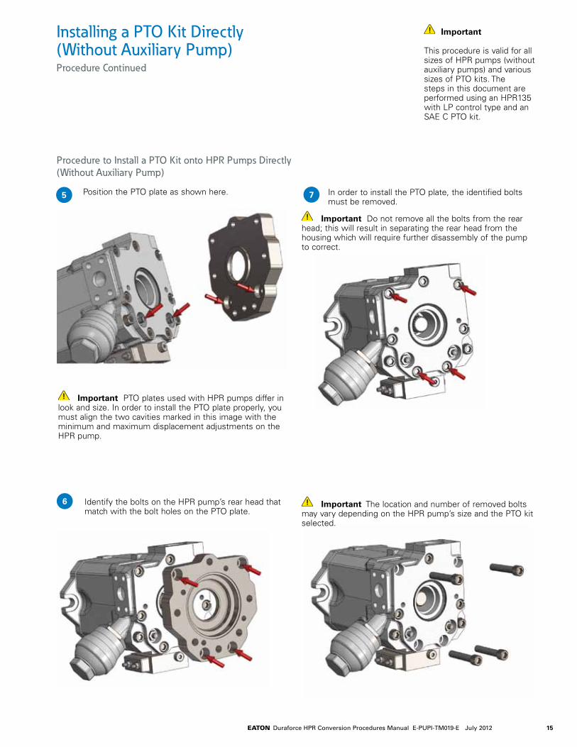
Installing a PTO Kit Directly (Without Auxiliary Pump)Procedure Continued
5
Important
This procedure is valid for all sizes of HPR pumps (without auxiliary pumps) and various sizes of PTO kits. The steps in this document are performed using an HPR135 with LP control type and an SAE C PTO kit.
Procedure to Install a PTO Kit onto HPR Pumps Directly (Without Auxiliary Pump)
Position the PTO plate as shown here.
Important PTO plates used with HPR pumps differ in look and size. In order to install the PTO plate properly, you must align the two cavities marked in this image with the minimum and maximum displacement adjustments on the HPR pump.
Identify the bolts on the HPR pump’s rear head that match with the bolt holes on the PTO plate.
In order to install the PTO plate, the identified bolts must be removed.
Important Do not remove all the bolts from the rear head; this will result in separating the rear head from the housing which will require further disassembly of the pump to correct.
Important The location and number of removed bolts may vary depending on the HPR pump’s size and the PTO kit selected.
6
7

16 EATON Duraforce HPR Conversion Procedures Manual E-PUPI-TM019-E July 2012
Installing a PTO Kit Directly (Without Auxiliary Pump)Procedure Continued
Important
This procedure is valid for all sizes of HPR pumps (without auxiliary pumps) and various sizes of PTO kits. The steps in this document are performed using an HPR135 with LP control type and an SAE C PTO kit.
Install the PTO plate on the HPR pump’s rear head as shown here.
Important Pay attention to the o-ring on the rear head to prevent damages.
Align bolt holes on the PTO plate with the holes on the rear head.
Install the new o-ring on the back of the PTO Plate using petroleum jelly.
Install the new PTO Cover as shown here.
Install the new bolts on the PTO plate as shown here.
Important These new bolts are longer than the original bolts removed from the rear head. For the correct bolt length and part number refer to Lindos.
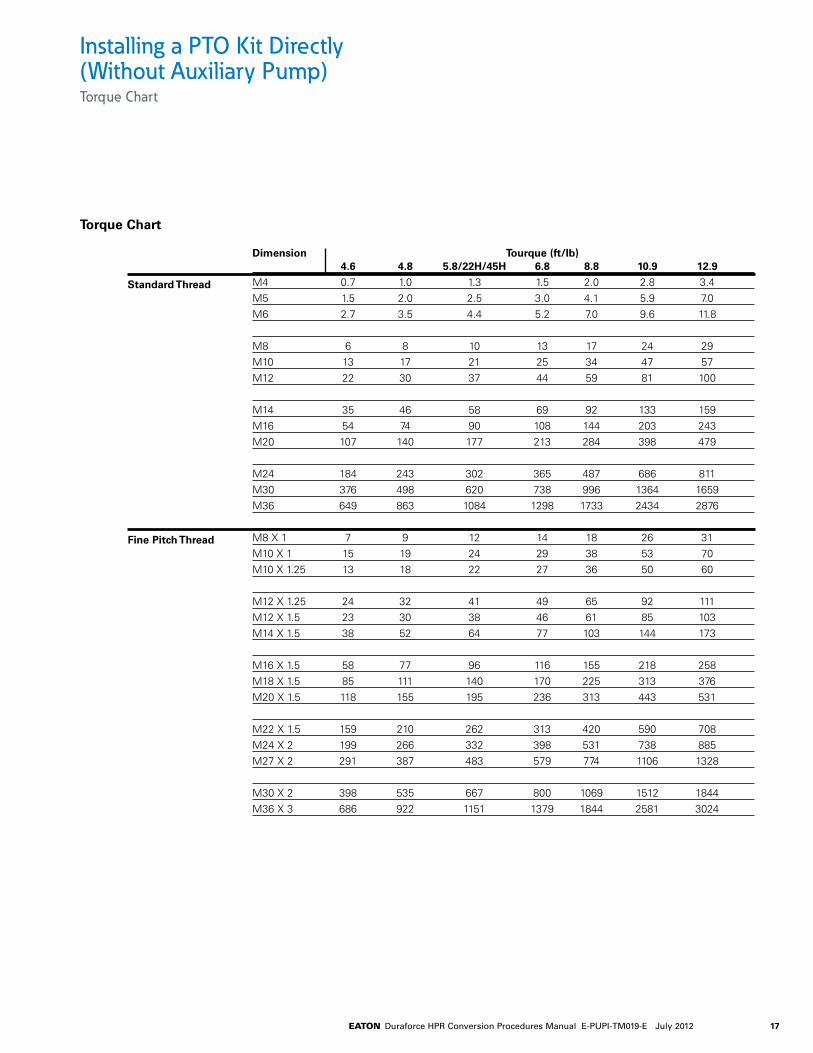
Torque the bolts. (See torque chart at the end of this document).
Tighten the bolts on the PTO cover.
8 12
13
149
10
11
17EATON Duraforce HPR Conversion Procedures Manual E-PUPI-TM019-E July 2012
Dimension Tourque (ft/lb) 4.6 4.8 5.8/22H/45H 6.8 8.8 10.9 12.9
M4 0.7 1.0 1.3 1.5 2.0 2.8 3.4M5 1.5 2.0 2.5 3.0 4.1 5.9 7.0M6 2.7 3.5 4.4 5.2 7.0 9.6 11.8
M8 6 8 10 13 17 24 29M10 13 17 21 25 34 47 57M12 22 30 37 44 59 81 100
M14 35 46 58 69 92 133 159M16 54 74 90 108 144 203 243M20 107 140 177 213 284 398 479
M24 184 243 302 365 487 686 811M30 376 498 620 738 996 1364 1659M36 649 863 1084 1298 1733 2434 2876
M8 X 1 7 9 12 14 18 26 31M10 X 1 15 19 24 29 38 53 70M10 X 1.25 13 18 22 27 36 50 60
M12 X 1.25 24 32 41 49 65 92 111M12 X 1.5 23 30 38 46 61 85 103M14 X 1.5 38 52 64 77 103 144 173
M16 X 1.5 58 77 96 116 155 218 258M18 X 1.5 85 111 140 170 225 313 376M20 X 1.5 118 155 195 236 313 443 531
M22 X 1.5 159 210 262 313 420 590 708M24 X 2 199 266 332 398 531 738 885M27 X 2 291 387 483 579 774 1106 1328
M30 X 2 398 535 667 800 1069 1512 1844M36 X 3 686 922 1151 1379 1844 2581 3024
Standard Thread
Torque Chart
Fine Pitch Thread
Installing a PTO Kit Directly (Without Auxiliary Pump)Torque Chart

18 EATON Duraforce HPR Conversion Procedures Manual E-PUPI-TM019-E July 2012
Maximum Displacement Adjustment ProcedureSet-up and Procedure
Note: The prime mover can be OFF for this procedure.
Use the figure above to determine where the “Maximum Displacement Adjustment“ is for the rotation of your pump.
Hold the adjustment stud stationary with the 6mm Allen wrench and loosen the seal nut with the 19mm wrench.
Turn the adjustment stud OUT until you feel it lose contact with the stroking piston inside of the pump.
Slowly turn the adjustment stud IN until you feel it just touch the stroking piston inside of the pump, then turn the adjustment stud IN 1/4 turn.
Hold the adjustment stud stationary with the 6mm Allen wrench and tighten the seal nut with the 19mm wrench (The proper torque for the seal nut is 60 N-m [44 ft-lb]).
1
Use the figure above to determine where the “Maximum Displacement Adjustment“ is for the rotation of your pump.
Start the prime mover and actuate a function that this pump supplies flow to. Make sure that the function you select can accommodate the full flow of the pump.
Hold the adjustment stud stationary with the 6mm Allen wrench and loosen the seal nut with the 19mm wrench.
Slowly turn the adjustment stud IN until the desired pump flow is acquired.
Hold the adjustment stud stationary with the 6mm Allen wrench and tighten the seal nut with the 19mm wrench (The proper torque for the seal nut is 60 N-m [44 ft-lb]).
Note: To decrease the maximum pump flow, turn the adjustment stud IN.
To increase the maximum pump flow, turn the adjustment stud OUT.
1
2
2
33
4 4
5 5
Important
If performing this procedure on a vehicle, care must be taken. The pump will be put on stroke during this procedure, hence all personnel should be removed from the area of the machine. If using the pump for a propelling function, then the vehicle must be safely elevated to allow the propel motor to free-wheel.
Important
These instructions are ONLY valid for single HPR pumps.
Adjustment Procedure to Set the Pump at Maximum Displacement
Adjustment Procedure to Destroke the Pump

19EATON Duraforce HPR Conversion Procedures Manual E-PUPI-TM019-E July 2012
Adjustment Procedure to Set the Pump at Minimum Displacement
With the prime mover OFF, disconnect the load sense line from the pump control block.
Securely plug the end of the load sense line.
Leave the load sense port on the pump control block vented to atmosphere.
Start the prime mover and adjust it to high idle.
To Adjust the Pump Minimum Displacement:
a Use the figure above to determine where the "Minimum Displacement Adjustment" is for the rotation of your pump.
b Hold the adjustment stud stationary with the 6mm Allen wrench.
c Loosen the seal nut with the 19mm wrench.
d Slowly turn the adjustment stud OUT until you feel it lose contact with the stroking piston inside of the pump.
Warning! The minimum displacement adjustment stud is NOT restricted from being removed completely from the pump. Care must be taken to insure you do not remove the adjustment stud completely from the pump.
e Slowly turn the adjustment stud IN until it just touches the stroking piston inside of the pump.
f Then turn the adjustment stud OUT 1/4 turn.
g Hold the adjustment stud stationary with the 6mm Allen wrench and tighten the seal nut with the 19mm wrench (The proper torque for the seal nut is 60 N-m [44 ft-lb]).
h Turn the prime mover OFF.
i Unplug the end of the load sense line and reconnect it to the load sense port on the pump control block.
Note: To decrease the minimum displacement, turn the adjustment stud OUT
To increase the minimum displacement, turn the adjustment stud IN
Minimum Displacement Adjustment ProcedureSet-up and Procedure
1
2
3
4
5
Note
This procedure is ONLY intended to be used if the pump minimum displacement setting has been altered or if the stand-by pressure is unusually high.
Important
These instructions are ONLY valid for single HPR pumps.

20 EATON Duraforce HPR Conversion Procedures Manual E-PUPI-TM019-E July 2012
Beneficial Conditions for Long Service Life
Speed Lower continuous maximum speedOperating Pressure Less tan 300 bar Δp on averageMax. Pressure Only at reduced displacementViscosity 15...30 cStPower Continuous power or lowerPurity of Fluid 18/16/13 in accordance with ISO 4406
or better
Adverse Factors Affecting Service Life
Speed Between continuous maximum speed and intermittent maximum speed
Operating pressure More than 300 bar Δp on averageViscosity Less than 10 cStPower Continuous operation close to maxi-
mum powerPurity of fluid Lower than 18/16/13 in accordance
with ISO 4406
1,25
1,2
1,15
1,1
1,05
1
0,95
0,9
0,850,5 0,55 0,65 0,75 0,85 0,95 10,6 0,7 0,8 0,9
Rel. Displacement V/ Vmax
Rel
. Sp
eed
n/n
rate
d
0,8 bar Absolute Suction Pressure
0,9 bar
1,0 bar
1,1 bar
1,2 bar
1,3 bar
Operational Parameters Life Time Recommendations
Eaton high pressure units are designed for excellent reliability and long service life. The actual service life of a hydraulic unit is determined by numerous factors. It can be extended significantly through proper maintenance of the hydraulic system and by using high-quality hydraulic fluid.
Operational Parameters. HPR Suction Speed
The leakage and decompression oil generated during pump operation is drained from the rotating group into the pump housing.
Excessive housing pressure must be avoided through suitably dimensioned piping between the housing and the tank.
For reliable proper function and long service life
18/16/13 in accordance with ISO 4406 or better
Commissioning The minimum cleanliness level requirement for the hydraulic oil is based on the most sensitive component. For commissioning we recommend a filtration in order to achieve the required cleanliness level.
Filling and operation of hydraulic systems The required cleanliness level of the hydraulic oil must be ensured during filling or topping up. When drums, canisters, or large-capacity tanks are used the oil generally has to be filtered. We recommend the implementation of suitable filters to ensure that the required cleanliness level of the oil is achieved and maintained during operation.
International standard Code Number According to ISO 4406 18/16/13
Tank connection
Operational Parameters. Filtration
In order to guarantee long-term proper function and high efficiency of the hydraulic pumps the
cleanliness level of the lubricant must comply with the following criteria according to Eaton
Hydraulic Fluid Recommendation 03-401-2010. Maintaining the recommended
cleanliness level can extend the service life of the hydraulic system significantly.
21EATON Duraforce HPR Conversion Procedures Manual E-PUPI-TM019-E July 2012
In order to be able to select the right hydraulic fluid it is necessary to know the working temperature in the hydraulic circuit. The hydraulic fluid should be selected such that its
optimum viscosity is within the working temperature range (see tables).
The temperature should not exceed 90 °C in any part of the system. Due to pressure and speed influences the leakage
fluid temperature is always higher than the circuit temperature. Please contact Eaton if the stated conditions cannot be met or in special circumstances.
In order to ensure the functional performance and high efficiency of the hydraulic pumps the viscosity and purity of the operating fluid should meet the different operational requirements. Eaton recommends using only hydraulic fluids which are confirmed by the manufacturer as suitable for use in high pressure hydraulic installations or approved by the original equipment manufacturer.
Permitted Pressure Fluids
• Mineral oil HLP to DIN 51 524-2
• Biodegradable fluids in accordance with ISO 15 380 on request
• Other pressure fluids on request
Eaton offers an oil testing service in accordance with VDMA 24 570 and the test apparatus required for in-house sesting. Prices available on request.
Recommended Viscosity RangesPressure Fluid Temperature Range [°C] -20 to +90
Working viscosity range [mm²/s] = [cSt] 10 to 80 Optimum working viscosity [mm²/s] = [cSt] 15 to 30 Max. viscosity (short time start up) [mm²/s] = [cSt] 1000
Operational ParametersPressure Fluids
Viscosity RecommendationsWorking Temperature [°C] Viscosity [mm²/s] = [cSt] at 40 °C
Approx. 30 to 40 22 Approx. 40 to 60 32 Approx. 60 to 80 46 or 68
Further information regarding installation can be found in the operating instructions.

22 EATON Duraforce HPR Conversion Procedures Manual E-PUPI-TM019-E July 2012
Eaton Part NumbersHPR Self-regulating Pump for Open Loop Operation
Part # Description Qty
5853400783 E1L, ISO port, 12V DIN 19045348186 Cap Screw 3
Controls - E1L, ISO Port, 12V DIN p. 8
Part # Description Qty
5853400793 H1L, ISO port 19045348186 Cap Screw 3
Controls - H1L, ISO Port p. 8
Part # Description Qty
5853400792 E1L, ISO port, 24V DIN 19045348186 Cap Screw 3
Controls - E1L, ISO Port, 24V DIN p. 8
Part # Description Qty
5853900728 LP, ISO port, 125-230 bar Press. Comp. 19045348186 Cap Screw 3
Controls - LP, ISO Port, 125-230 bar Press. Comp. p. 8
Part # Description Qty
5853400787 E1L, ISO port, 12V AMP 19045348186 Cap Screw 3
Controls - E1L, ISO Port, 12V AMP p. 8
Part # Description Qty
5853900727 LP, ISO port, 231-350 bar Press. Comp. 19045348186 Cap Screw 3
Controls - LP, ISO Port, 231-350 bar Press. Comp. p. 8
Part # Description Qty
5853400784 E1L, ISO port, 24V AMP 19045348186 Cap Screw 3
Controls - E1L, ISO Port, 24V AMP p. 8
Part # Description Qty
5853900726 LP, ISO port, 351-420 bar Press. Comp. 19045348186 Cap Screw 3
Controls - LP, ISO Port, 351-420 bar Press. Comp. p. 8
Part # Description Qty
0009218401 Spring 1
Horsepower Spring - TL2/ETP p. 9
Part # Description Qty
0009736084 Coil, 12V AMP 19045371087 Cap Screw 40009632216 O-ring 1
E1L Solenoid - 12V AMP p. 11
Part # Description Qty
0009736025 Coil, 12V DIN 17915001590 Seal 10009750508 DIN Plug 19045311080 Cap Screw 40009632216 O-ring 1
E1L Solenoid - 12V DIN p. 11
Part # Description Qty
0009736125 Coil, 24V AMP 19045371087 Cap Screw 40009632216 O-ring 1
E1L Solenoid - 24V AMP p. 11
Part # Description Qty
0009736026 Coil, 24V DIN 17915001590 Seal 10009750508 DIN Plug 19045311080 Cap Screw 40009632216 O-ring 1
E1L Solenoid - 24V DIN p. 11

23EATON Duraforce HPR Conversion Procedures Manual E-PUPI-TM019-E July 2012
Eaton Part NumbersHPR Self-regulating Pump for Open Loop Operation
Part # Description Qty
0009630840 O-ring 12533051204 9T Coupling 12533061300 Cover 19008311295 Cap Screw 2
HPR055 Auxiliary Flange - SAE "A" Flange W/ 9T Coupling p. 12
Part # Description Qty
0009630840 O-ring 12622311411 Flange, SAE B 10009631058 O-ring 12713061301 Cover 19008311302 Cap Screw 2
Part # Description Qty
0009630840 O-ring 12633051208 13T Coupling 12622311411 Flange, SAE B 10009631058 O-ring 12713061301 Cover 19008311302 Cap Screw 2
Part # Description Qty
0009630840 O-ring 12633051207 15T Coupling 12622311411 Flange, SAE B 10009631058 O-ring 12713061301 Cover 19008311302 Cap Screw 2
HPR055 Auxiliary Flange - SAE "B" Flange W/out Coupling p. 12
HPR055 Auxiliary Flange - SAE "B" Flange W/ 13T Coupling p. 12
HPR055 Auxiliary Flange - SAE "B" Flange W/ 15T Coupling p. 12
Part # Description Qty
0009630840 O-ring 19045341308 Cap Screw 42632311402 Flange, SAE C 19045341318 Cap Screw 40009631107 O-ring 10009611084 Seal 10009646551 Cover 19008311406 Cap Screw 2
HPR055 Auxiliary Flange - SAE "C" Flange W/out Coupling p. 12
Part # Description Qty
0009630840 O-ring 19045341308 Cap Screw 42632311402 Flange, SAE C 19045341318 Cap Screw 40009631107 O-ring 10009611084 Seal 10009646551 Cover 12533051205 14T Coupling 19008311406 Cap Screw 2
HPR055 Auxiliary Flange - SAE "C" Flange W/ 14T Coupling p. 12

24 EATON Duraforce HPR Conversion Procedures Manual E-PUPI-TM019-E July 2012
Eaton Part NumbersHPR Self-regulating Pump for Open Loop Operation
Part # Description Qty
0009630840 O-ring 12533051204 9T Coupling 12533061300 Cover 19008311295 Cap Screw 2
HPR075 Auxiliary Flange - SAE "A" Flange W/ 9T Coupling p. 12
Part # Description Qty
0009630840 O-ring 12622311411 Flange, SAE B 10009631058 O-ring 12713061301 Cover 19008311302 Cap Screw 2
Part # Description Qty
0009630840 O-ring 12633051208 13T Coupling 12622311411 Flange, SAE B 10009631058 O-ring 12713061301 Cover 19008311302 Cap Screw 2
Part # Description Qty
0009630840 O-ring 12633051207 15T Coupling 12622311411 Flange, SAE B 10009631058 O-ring 12713061301 Cover 19008311302 Cap Screw 2
HPR075 Auxiliary Flange - SAE "B" Flange W/out Coupling p. 12
HPR075 Auxiliary Flange - SAE "B" Flange W/ 13T Coupling p. 12
HPR075 Auxiliary Flange - SAE "B" Flange W/ 15T Coupling p. 12
Part # Description Qty
0009630840 O-ring 19045341308 Cap Screw 42632311402 Flange, SAE C 19045341318 Cap Screw 40009631107 O-ring 10009611084 Seal 10009646551 Cover 19008311406 Cap Screw 2
HPR075 Auxiliary Flange - SAE "C" Flange W/out Coupling p. 12
Part # Description Qty
0009630840 O-ring 19045341308 Cap Screw 42632311402 Flange, SAE C 19045341318 Cap Screw 40009631107 O-ring 10009611084 Seal 10009646551 Cover 12533051205 14T Coupling 19008311406 Cap Screw 2
HPR075 Auxiliary Flange - SAE "C" Flange W/ 14T Coupling p. 12
Part # Description Qty
0009630840 O-ring 19045341308 Cap Screw 42632311402 Flange, SAE C 19045341318 Cap Screw 40009631107 O-ring 10009611084 Seal 10009646551 Cover 15973051201 21T Coupling 19008311406 Cap Screw 2
HPR075 Auxiliary Flange - SAE "C" Flange W/ 21T Coupling p. 12

25EATON Duraforce HPR Conversion Procedures Manual E-PUPI-TM019-E July 2012
Eaton Part NumbersHPR Self-regulating Pump for Open Loop Operation
Part # Description Qty
0009630840 O-ring 12543051201 9T Coupling 15813061302 Cover 19008311241 Cap Screw 2
HPR105 Auxiliary Flange - SAE "A" Flange W/ 9T Coupling p. 12
Part # Description Qty
0009630840 O-ring 12622311411 Flange, SAE B 10009631058 O-ring 12713061301 Cover 19008311304 Cap Screw 2
Part # Description Qty
0009630840 O-ring 12622311411 Flange, SAE B 10009631058 O-ring 12543051202 13T Coupling 12713061301 Cover 19008311304 Cap Screw 2
Part # Description Qty
0009630840 O-ring 12622311411 Flange, SAE B 10009631058 O-ring 12643051208 15T Coupling 12713061301 Cover 19008311304 Cap Screw 2
HPR105 Auxiliary Flange- SAE "B" Flange W/out Coupling p. 12
HPR105 Auxiliary Flange - SAE "B" Flange W/ 13T Coupling p. 12
HPR105 Auxiliary Flange- SAE "B" Flange W/ 15T Coupling p. 12
Part # Description Qty
0009630840 O-ring 19045341310 Cap Screw 52642311411 Flange, SAE C 19045341318 Cap Screw 40009631107 O-ring 10009611084 Seal 10009646551 Cover 19008311408 Cap Screw 2
HPR105 Auxiliary Flange - SAE "C" Flange W/out Coupling p. 12
Part # Description Qty
0009630840 O-ring 19045341310 Cap Screw 52642311411 Flange, SAE C 19045341318 Cap Screw 40009631107 O-ring 10009611084 Seal 10009646551 Cover 12643051206 14T Coupling 19008311408 Cap Screw 2
HPR105 Auxiliary Flange - SAE "C" Flange W/ 14T Coupling p. 12
Part # Description Qty
0009630840 O-ring 19045341310 Cap Screw 52642311411 Flange, SAE C 19045341318 Cap Screw 40009631107 O-ring 10009611084 Seal 10009646551 Cover 12643051203 21T Coupling 19008311408 Cap Screw 2
HPR105 Auxiliary Flange - SAE "C" Flange W/ 21T Coupling p. 12
Part # Description Qty
0009630840 O-ring 19045341310 Cap Screw 52642311411 Flange, SAE C 19045341318 Cap Screw 40009631107 O-ring 10009611084 Seal 10009646551 Cover 12643051201 23T Coupling 19008311408 Cap Screw 2
HPR105 Auxiliary Flange - SAE "C" Flange W/23T Coupling p. 12
26 EATON Duraforce HPR Conversion Procedures Manual E-PUPI-TM019-E July 2012
Eaton Part NumbersHPR Self-regulating Pump for Open Loop Operation
Part # Description Qty
0009630840 O-ring 12553051203 9T Coupling 12733061300 Cover 19045311236 Cap Screw 2
HPR135 Auxiliary Flange - SAE "A" Flange W/ 9T Coupling p. 12
Part # Description Qty
0009630840 O-ring 12622311411 Flange, SAE B 10009631058 O-ring 12713061301 Cover 19008311304 Cap Screw 2
Part # Description Qty
0009630840 O-ring 12622311411 Flange, SAE B 10009631058 O-ring 12653051210 13T Coupling 12713061301 Cover 19008311304 Cap Screw 2
Part # Description Qty
0009630840 O-ring 12622311411 Flange, SAE B 10009631058 O-ring 12653051208 15T Coupling 12713061301 Cover 19008311304 Cap Screw 2
HPR135 Auxiliary Flange - SAE "B" Flange W/out Coupling p. 12
HPR135 Auxiliary Flange - SAE "B" Flange W/ 13T Coupling p. 12
HPR135 Auxiliary Flange - SAE "B" Flange W/ 15T Coupling p. 12
Part # Description Qty
0009630840 O-ring 19045341367 Cap Screw 55992311408 Flange, SAE C 19045341372 Cap Screw 40009631107 O-ring 10009611084 Seal 10009646551 Cover 19008311408 Cap Screw 2
HPR135 Auxiliary Flange - SAE "C" Flange W/out Coupling p. 12
Part # Description Qty
0009630840 O-ring 19045341367 Cap Screw 55992311408 Flange, SAE C 19045341372 Cap Screw 40009631107 O-ring 10009611084 Seal 10009646551 Cover 15993051209 14T Coupling 19008311408 Cap Screw 2
HPR135 Auxiliary Flange - SAE "C" Flange W/ 14T Coupling p. 12

27EATON Duraforce HPR Conversion Procedures Manual E-PUPI-TM019-E July 2012
Eaton Part NumbersHPR Self-regulating Pump for Open Loop Operation
Part # Description Qty
0009630840 O-ring 19045341367 Cap Screw 55992311411 Flange, SAE D 19045341397 Cap Screw 40009631126 O-ring 10009646548 Cover 19045316524 Cap Screw 2
HPR135 Auxiliary Flange - SAE "D" Flange W/out Coupling p. 12
Part # Description Qty
0009630840 O-ring 19045341367 Cap Screw 55992311411 Flange, SAE D 19045341397 Cap Screw 40009631126 O-ring 10009646548 Cover 12553051207 13T Coupling 19045316524 Cap Screw 2
HPR135 Auxiliary Flange - SAE "D" Flange W/13T Coupling p. 12
Part # Description Qty
0009630840 O-ring 19045341367 Cap Screw 55992311411 Flange, SAE D 19045341397 Cap Screw 40009631126 O-ring 10009646548 Cover 12653051205 17T Coupling 19045316524 Cap Screw 2
HPR135 Auxiliary Flange - SAE "D" Flange W/17T Coupling p. 12
Part # Description Qty
0009630840 O-ring 19045341367 Cap Screw 55992311411 Flange, SAE D 19045341397 Cap Screw 40009631126 O-ring 10009646548 Cover 15993051211 27T Coupling 19045316524 Cap Screw 2
HPR135 Auxiliary Flange - SAE "D" Flange W/27T Coupling p. 12
Part # Description Qty
0009630840 O-ring 19045341367 Cap Screw 55992311408 Flange, SAE C 19045341372 Cap Screw 40009631107 O-ring 10009611084 Seal 10009646551 Cover 15993051207 21T Coupling 19008311408 Cap Screw 2
HPR135 Auxiliary Flange - SAE "C" Flange W/ 21T Coupling p. 12
Part # Description Qty
0009630840 O-ring 19045341367 Cap Screw 55992311408 Flange, SAE C 19045341372 Cap Screw 40009631107 O-ring 10009611084 Seal 10009646551 Cover 15993051206 23T Coupling 19008311408 Cap Screw 2
HPR135 Auxiliary Flange - SAE "C" Flange W/23T Coupling p. 12

28 EATON Duraforce HPR Conversion Procedures Manual E-PUPI-TM019-E July 2012
Eaton Part NumbersHPR Self-regulating Pump for Open Loop Operation
Part # Description Qty
0009630840 O-ring 12563051200 9T Coupling 15813061302 Cover 19008311233 Cap Screw 2
HPR165 Auxiliary Flange - SAE "A" Flange W/ 9T Coupling p. 12
Part # Description Qty
0009630840 O-ring 12712311402 Flange, SAE B 10009631058 O-ring 12713061301 Cover 19008311302 Cap Screw 2
Part # Description Qty
0009630840 O-ring 12712311402 Flange, SAE B 10009631058 O-ring 15993051214 13T Coupling 12713061301 Cover 19008311302 Cap Screw 2
Part # Description Qty
0009630840 O-ring 19045341373 Cap Screw 42562311403 Flange, SAE C 19045341385 Cap Screw 40009631107 O-ring 10009611084 Seal 10009646551 Cover 19008311408 Cap Screw 2
HPR165 Auxiliary Flange - SAE "B" Flange W/ out Coupling p. 12
HPR105 Auxiliary Flange - SAE "B" Flange W/ 13T Coupling p. 12
HPR165 Auxiliary Flange - SAE "C" Flange W/out Coupling p. 12
Part # Description Qty
0009630840 O-ring 19045341373 Cap Screw 42562311403 Flange, SAE C 19045341385 Cap Screw 40009631107 O-ring 10009611084 Seal 10009646551 Cover 15993051213 14T Coupling 19008311408 Cap Screw 2
HPR165 Auxiliary Flange - SAE "C" Flange W/14T Coupling p. 12
Part # Description Qty
0009630840 O-ring 19045341373 Cap Screw 42562311403 Flange, SAE C 19045341385 Cap Screw 40009631107 O-ring 10009611084 Seal 10009646551 Cover 15993051212 23T Coupling 19008311408 Cap Screw 2
HPR165 Auxiliary Flange - SAE "C" Flange W/23T Coupling p. 12
Part # Description Qty
0009630840 O-ring 19045341373 Cap Screw 42562311405 Flange, SAE D 19045341378 Cap Screw 40009631126 O-ring 10009646548 Cover 19045316524 Cap Screw 2
HPR165 Auxiliary Flange - SAE "D" Flange W/out Coupling p. 12
Part # Description Qty
0009630840 O-ring 19045341373 Cap Screw 42562311405 Flange, SAE D 19045341378 Cap Screw 40009631126 O-ring 10009646548 Cover 12563051202 27T Coupling 19045316524 Cap Screw 2
HPR165 Auxiliary Flange - SAE "D" Flange W/27T Coupling p. 12

29EATON Duraforce HPR Conversion Procedures Manual E-PUPI-TM019-E July 2012
Eaton Part NumbersHPR Self-regulating Pump for Open Loop Operation
Part # Description Qty
0009630840 O-ring 12573051211 9T Coupling 15813061302 Cover 19008311233 Cap Screw 2
HPR210 Auxiliary Flange - SAE "A" Flange W/ 9T Coupling p. 12
Part # Description Qty
0009630840 O-ring 12573051201 11T Coupling 15813061302 Cover 19008311233 Cap Screw 2
Part # Description Qty
0009630840 O-ring 12573051207 13T Coupling 15813061302 Cover 19008311233 Cap Screw 2
Part # Description Qty
0009630840 O-ring 12712311402 Flange, SAE B 10009631058 O-ring 12713061301 Cover 19008311302 Cap Screw 2
HPR210 Auxiliary Flange - SAE "A" Flange W/ 11T Coupling p. 12
HPR210 Auxiliary Flange - SAE "A" Flange W/ 13T Coupling p. 12
HPR210 Auxiliary Flange - SAE "B" Flange W/ out Coupling p. 12
Part # Description Qty
0009630840 O-ring 12712311402 Flange, SAE B 10009631058 O-ring 12573051209 13T Coupling 12713061301 Cover 19008311302 Cap Screw 2
HPR210 Auxiliary Flange - SAE "B" Flange W/ 13T Coupling p. 12
Part # Description Qty
0009630840 O-ring 19045341372 Cap Screw 52572311405 Flange, SAE C 19045341385 Cap Screw 40009631107 O-ring 10009611084 Seal 10009646551 Cover 19008311408 Cap Screw 2
HPR210 Auxiliary Flange - SAE "C" Flange W/out Coupling p. 12
Part # Description Qty
0009630840 O-ring 19045341372 Cap Screw 52572311405 Flange, SAE C 19045341385 Cap Screw 40009631107 O-ring 10009611084 Seal 10009646551 Cover 12573051205 14T Coupling 19008311408 Cap Screw 2
HPR210 Auxiliary Flange - SAE "C" Flange W/14T Coupling p. 12
Part # Description Qty
0009630840 O-ring 19045341372 Cap Screw 52572311405 Flange, SAE C 19045341385 Cap Screw 40009631107 O-ring 10009611084 Seal 10009646551 Cover 12573051212 21T Coupling 19008311408 Cap Screw 2
HPR210 Auxiliary Flange - SAE "C" Flange W/21T Coupling p. 12
30 EATON Duraforce HPR Conversion Procedures Manual E-PUPI-TM019-E July 2012
Eaton Part NumbersHPR Self-regulating Pump for Open Loop Operation
Part # Description Qty
0009630840 O-ring 19045341372 Cap Screw 52572311405 Flange, SAE C 19045341385 Cap Screw 40009631107 O-ring 10009611084 Seal 10009646551 Cover 12573051206 23T Coupling 19008311408 Cap Screw 2
HPR210 Auxiliary Flange - SAE "C" Flange W/23T Coupling p. 12
Part # Description Qty
0009630840 O-ring 19045341372 Cap Screw 52572311407 Flange, SAE D 19045341379 Cap Screw 40009631126 O-ring 10009646548 Cover 19045316524 Cap Screw 2
HPR210 Auxiliary Flange - SAE "D" Flange W/out Coupling p. 12
Part # Description Qty
0009630840 O-ring 19045341372 Cap Screw 52572311407 Flange, SAE D 19045341379 Cap Screw 40009631126 O-ring 10009646548 Cover 12573051202 27T Coupling 19045316524 Cap Screw 2
HPR210 Auxiliary Flange - SAE "D" Flange W/27T Coupling p. 12
Part # Description Qty
0009630840 O-ring 19045341372 Cap Screw 42672311406 Flange, SAE E 19045341378 Cap Screw 50009631102 O-ring 10009180164 Cover 19045316524 Cap Screw 4
HPR210 Auxiliary Flange - SAE "E" Flange W/out Coupling p. 12
Part # Description Qty
0009630840 O-ring 19045341372 Cap Screw 42672311406 Flange, SAE E 19045341378 Cap Screw 50009631102 O-ring 10009180164 Cover 12573051208 27T Coupling 19045316524 Cap Screw 4
HPR210 Auxiliary Flange - SAE "D" Flange W/27T Coupling p. 12

31EATON Duraforce HPR Conversion Procedures Manual E-PUPI-TM019-E July 2012
Eaton Part NumbersHPR Self-regulating Pump for Open Loop Operation
Part # Description Qty
0009630840 O-ring 12223051201 13T Coupling 15813061302 Cover 19008311233 Cap Screw 2
HPR280 Auxiliary Flange - SAE "A" Flange W/ 13T Coupling p. 12
Part # Description Qty
0009630840 O-ring 12712311402 Flange, SAE B 10009631058 O-ring 12713061301 Cover 19008311302 Cap Screw 2
Part # Description Qty
0009630840 O-ring 12712311402 Flange, SAE B 10009631058 O-ring 12223051207 13T Coupling 12713061301 Cover 19008311302 Cap Screw 2
Part # Description Qty
0009630840 O-ring 12712311402 Flange, SAE B 10009631058 O-ring 12223051209 15T Coupling 12713061301 Cover 19008311302 Cap Screw 2
HPR280 Auxiliary Flange - SAE "B" Flange W/ out Coupling p. 12
HPR280 Auxiliary Flange - SAE "B" Flange W/ 13T Coupling p. 12
HPR280 Auxiliary Flange - SAE "B" Flange W/ 15T Coupling p. 12
Part # Description Qty
0009630840 O-ring 19045371424 Cap Screw 72222311405 Flange, SAE C 19045371431 Cap Screw 20009631107 O-ring 10009611084 Seal 10009646551 Cover 19008311408 Cap Screw 2
HPR280 Auxiliary Flange - SAE "C" Flange W/out Coupling p. 12
Part # Description Qty
0009630840 O-ring 19045371424 Cap Screw 72222311405 Flange, SAE C 19045371431 Cap Screw 20009631107 O-ring 10009611084 Seal 10009646551 Cover 12223051210 14T Coupling 19008311408 Cap Screw 2
HPR280 Auxiliary Flange - SAE "C" Flange W/14T Coupling p. 12
Part # Description Qty
0009630840 O-ring 19045371424 Cap Screw 42222311406 Flange, SAE D 19045371431 Cap Screw 50009631126 O-ring 10009646548 Cover 19045316524 Cap Screw 2
HPR280 Auxiliary Flange - SAE "D" Flange W/out Coupling p. 12
Part # Description Qty
0009630840 O-ring 19045371424 Cap Screw 42222311404 Flange, SAE E 19045371431 Cap Screw 50009631102 O-ring 10009180164 Cover 19045316524 Cap Screw 4
HPR280 Auxiliary Flange - SAE "E" Flange W/out Coupling p. 12

EatonHydraulics Group USA14615 Lone Oak RoadEden Prairie, MN 55344USATel: 952-937-9800Fax: 952-294-7722www.eaton.com/hydraulics
EatonHydraulics Group EuropeRoute de la Longeraie 71110 MorgesSwitzerlandTel: +41 (0) 21 811 4600Fax: +41 (0) 21 811 4601
Eaton Hydraulics Group Asia PacificEaton BuildingNo.7 Lane 280 Linhong Road Changning District, Shanghai200335 ChinaTel: (+86 21) 5200 0099Fax: (+86 21) 2230 7240
© 2012 Eaton CorporationAll Rights Reserved Printed in USADocument No. E-PUPI-TM019-EJuly 2012