eaton electric vehicle 2-speed transmission …pub/@eaton/@roadranger/documents/...eaton electric...
TRANSCRIPT

Eaton Electric Vehicle 2-Speed Transmission TRSM7202 EN-US May 2016
EEV-7202
Service Manual

2
TABLE OF CONTENTS
Section 1 General
1. Safety - Alert Symbol And Terms…………...….…………………………………………………...…….4
2. Purpose and Scope of Manual………………………………………………………………………..….....5
3. How to Use This Manual………………………. …………………………………...………………..…...5
4. Serial Tag Information and Model Nomenclature…………………………………...………………...…..6
5. General Description - Features …………………………………………………………………….….…..8
6. The Epicyclic Reduction Gear...……………………………………………...……………………….…...9
7. Specifications Eaton 2-Speed Transmission ……………….………………………………………….....10
8. Features Description……………………………………………………………………………………...11
9. Setting Values …….……………………………………………………………………………………...12
10. Disassembly precautions and inspection of expendable parts……...…………………………………….13
11. Assembly precautions ….……………………………………………………………………………......15
12. Lubrication recommendations ...………………………………………………...…………………….....16
13. Maintenance Interval Chart……………………………………………………...…………………….....17
14. Lubrication checking procedure………………………………………………...……………………......18
15. Operating Temperature…………………………………….…………………...…………………….......19
16. Power Flow………………………………………………………………...………………………..........20
17. Air System………………………………………………………………...………………………...........21
18. Tightening Torques ……………………………………………………………...……………………….22
19. Loctite locations…………………………………………...…………………………………………......23
20. Special Service Tools……………………………………...…………………………………………......24
Section 2 Main Transmission Overhaul
1. Transmission Case – Dis-assembly…. …………………………………...………………………….......26
2. Front Cover dis-Dis-assembly ...…….………………...……………...………………………………….33
3. Intermediate Case Dis-assembly ….………………………...……...…………………………………….34
4. Rear Case Dis-assembly ….…………...…………...………………………………………………….....35
5. Planet Gear Carrier Dis-assembly ….……………………......………………………………………......42
6. Planet Gear Carrier Assembly ….……………………......………………………………………............44
7. Rear Case Piston & Range Cylinder Assembly…………..………………………………………...........47
8. Rear Case Assembly ………………….…………………………………...……………………..............49

3
Section 1 - General

4
Introduction
SAFETY - ALERT SYMBOL AND TERMS
This Safety Alert Symbol means ATTENTION! BE ALERT! YOUR SAFETY IS INVOLVED!
Remember that YOU are the key to safety. Good safety practices not only protect you, but also the people around you. Study the features in this manual and make them a working part of your safety program. Keep in mind that this safety section is written only for this manual. Practice all other usual and customary safe working precautions, and above all - REMEMBER – SAFETY IS YOUR RESPONSIBILITY. YOU CAN PREVENT SERIOUS INJURY OR DEATH.
SAFETY – SYMBOLS: DANGER, WARNING and CAUTION Whenever you see the words and symbols shown below, used in this book and on decals, you MUST take note of their instructions. The safety alert symbol identifies important safety messages on machines, safety signs, in manuals, or elsewhere. When you see this symbol, be alert to the possibility of personal injury or death. Follow the instructions given in the safety messages.
DANGER: The symbol and the word DANGER indicates an imminently hazardous situation which, if not avoided, will result in DEATH OR SERIOUS INJURY.
WARNING: The symbol and the word WARNING indicates a potentially hazardous situation. If the instructions or procedures are not correctly followed it could result in PERSONAL INJURY, OR LOSS OF LIFE.
CAUTION: The symbol and the word CAUTION identifies special instructions or procedure which if not strictly observed, could result in DAMAGE, DESTRUCTION OF EQUIPMENT, OR PERSONAL INJURY.
Note: The word NOTE indicates additional detail that will aid in the diagnosis or repair of a component/system for more efficient and convenient repair or operation.
The safety alert symbol identifies important safety messages on machines, safety signs, in manuals, or elsewhere. When you see this symbol, be alert to the possibility of personal injury or death. Follow the instructions given in the safety messages.
Why is SAFETY important to you? *ACCIDENTS DISABLE AND KILL * ACCIDENTS CAN BE AVOIDED * ACCIDENTS ARE COSTLY
Work Safely – Follow these Rules 1. Always wear safety glasses when using a hammer, chisel or
other tools that may cause chips to fly. 2. Use proper tools to make repairs; using hammers and chisels or
punches instead of pullers increases the probability of injury. 3. Keep work area organized and clean. Wipe up oil or spills of any
kind. Do not keep tools and parts on the floor. Eliminate the possibility of a fall which could result in a serious injury.
4. Be sure to reinstall safety devices, guards or shields after adjusting and/or servicing the machine.
5. After servicing, be sure all tools, parts, or servicing equipment are removed from the vehicle.
6. Use a safety catch on all hoist hooks. Do not take a chance; the load could slip off the hook.
7. Batteries give off explosive hydrogen gas when charging and continue to do so for some time after receiving a steady charge. Do not under any circumstances allow an electric spark or an open flame near the battery. Always disconnect a battery cable before working on the electrical system. Always wear safety goggles when servicing batteries.
8. Be careful when using compressed air to dry parts. Use approved air blow guns, do not exceed 2.5 bar, wear safety glass or goggles and use proper shielding to protect everyone in the work area.
9. Do not wear rings, wrist watches or loose fitting clothing when working on machinery because they could catch on moving parts causing serious injury. Wear sturdy, rough soled work shoes. Never carry out repairs and/or service with bare feet or while wearing sandals or sneakers.
10. Exhaust gases are highly poisonous! Therefore, do not start the engine in closed rooms unless adequate ventilation is ensured.
11. Before starting a vehicle always be seated in the driver’s seat, place the transmission in neutral, set the parking brakes and disengage the clutch.
12. Anytime you will be working on a vehicle, parking a vehicle, or leaving the cab with the engine running, place the transmission in neutral, set the parking brakes, and block the wheels.
13. For safety reasons, always engage the service brakes prior to selecting gear positions from “N”.
14. Before working on a vehicle or leaving the cab while the engine is running you must place the shift lever in “N”, set the parking brake, and block the wheels.
15. When parking the vehicle or leaving it you must place the shift lever in “N” and set the parking brake.
16. If the engine cranks in any gear other than Neutral, service your vehicle immediately.
17. Before towing the vehicle place the transmission in neutral, and lift the rear wheels off the ground, remove the axle shafts, or disconnect the driveline to avoid damage to the transmission during towing.
18. Always use genuine Eaton replacement parts. 19. Read this manual carefully and keep it in a convenient place for
future reference. 20. The description and specifications contained in this service
publication are current at the time of printing. 21. Eaton Corporation reserves the right to discontinue or modify its
models and/or procedures and to change specifications at any time without notice.
22. Any reference to brand name in this publication is made as an example of the types of tools and materials recommended for use and should not be considered an endorsement. Equivalents may be used.
23. Departure from the instructions, choice of tools, materials and recommended parts mentioned in this publication may jeopardize the personal safety of the service technician or vehicle operator.

5
Purpose and Scope of Manual This manual is designed to provide detailed information necessary to service and repair the Eaton transmission EEV-7202. How to Use This Manual The manual describes Transmission Overhaul Procedures-Bench Service. Transmission Overhaul Procedures follow the general steps for complete disassembly and then assembly of the transmission. Note: In some instances the transmission appearance may be different from the illustrations, but the procedure is the same. Images are representative.

6
Serial Tag Information and Model Nomenclature Transmission model designation and other transmission identification information is stamped on the transmission tag. To identify the transmission model designation and serial number, locate the tag on the transmission and then locate the numbers as shown below. When calling for service assistance or parts, have the model and serial numbers ready.
Do not remove or destroy the transmission identification tag. Transmission Tag and Location

7
The Eaton medium duty 2-speed transmissions are fitted with an identification plate located on the right hand side of the case. The identification plate shows the following details:
1. Model
2. Serial Number
3. Specification Number
4. Date code
Model (Model Number) The model number gives the broad specifications of the basic model of the transmission as explained below. This number and TA number both are necessary when calling for service assistance or replacement parts. Serial (SERIAL NUMBER) The serial number is the sequential identification number of the transmission. Before calling for service assistance, write the number down. It may be needed. Specification Number This number is written below the Serial. It is the reference number used by Eaton and is necessary with basic model number for correct technical support. CUSTOMER’S NUMBER This number is written below specification number. (Example indicated above)
8
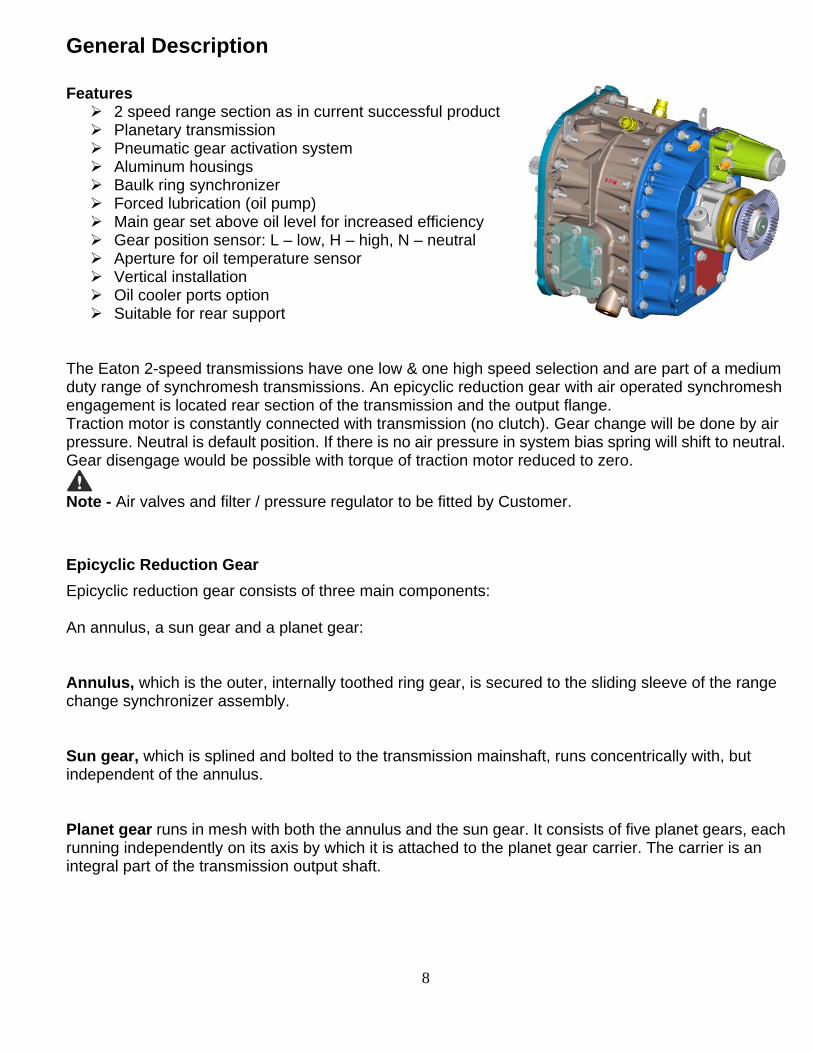
General Description Features 2 speed range section as in current successful product Planetary transmission Pneumatic gear activation system Aluminum housings Baulk ring synchronizer Forced lubrication (oil pump) Main gear set above oil level for increased efficiency Gear position sensor: L – low, H – high, N – neutral Aperture for oil temperature sensor Vertical installation Oil cooler ports option Suitable for rear support
The Eaton 2-speed transmissions have one low & one high speed selection and are part of a medium duty range of synchromesh transmissions. An epicyclic reduction gear with air operated synchromesh engagement is located rear section of the transmission and the output flange. Traction motor is constantly connected with transmission (no clutch). Gear change will be done by air pressure. Neutral is default position. If there is no air pressure in system bias spring will shift to neutral. Gear disengage would be possible with torque of traction motor reduced to zero.
Note - Air valves and filter / pressure regulator to be fitted by Customer.
Epicyclic Reduction Gear
Epicyclic reduction gear consists of three main components: An annulus, a sun gear and a planet gear: Annulus, which is the outer, internally toothed ring gear, is secured to the sliding sleeve of the range change synchronizer assembly. Sun gear, which is splined and bolted to the transmission mainshaft, runs concentrically with, but independent of the annulus. Planet gear runs in mesh with both the annulus and the sun gear. It consists of five planet gears, each running independently on its axis by which it is attached to the planet gear carrier. The carrier is an integral part of the transmission output shaft.
9
The Epicyclic Reduction Gear
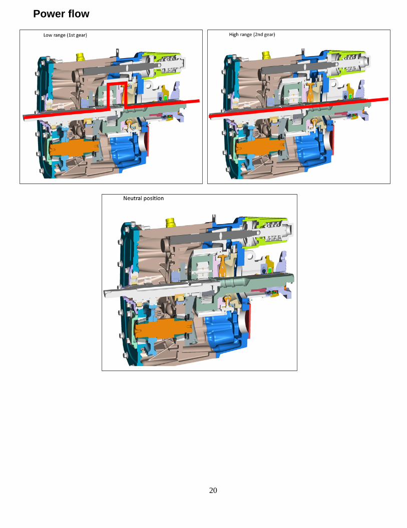
Principle
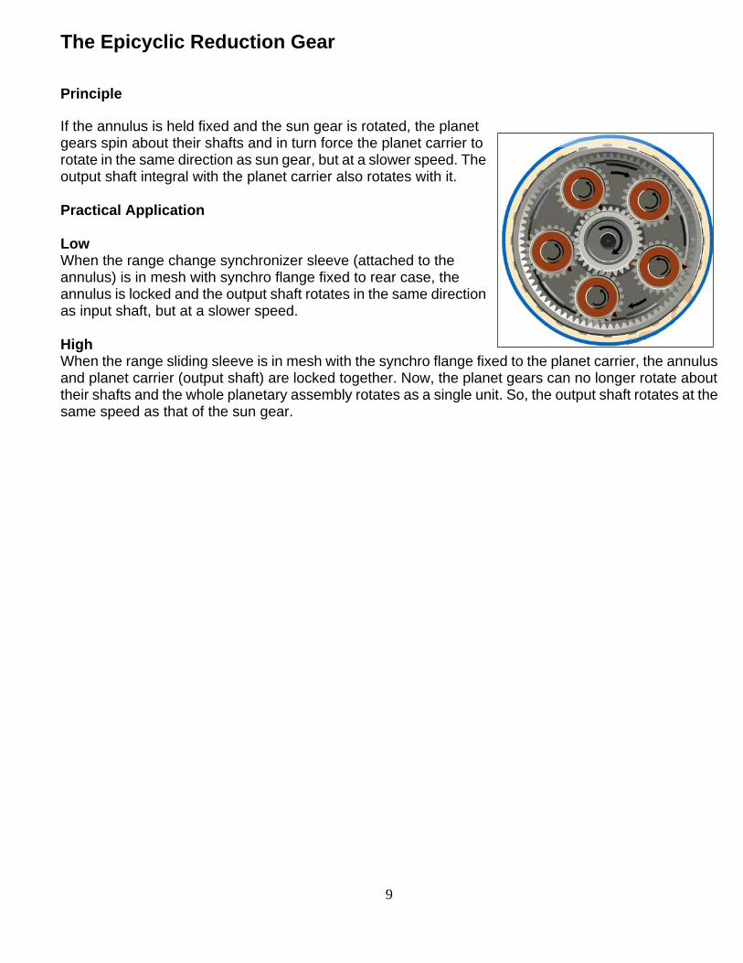
If the annulus is held fixed and the sun gear is rotated, the planet gears spin about their shafts and in turn force the planet carrier to rotate in the same direction as sun gear, but at a slower speed. The output shaft integral with the planet carrier also rotates with it. Practical Application Low When the range change synchronizer sleeve (attached to the annulus) is in mesh with synchro flange fixed to rear case, the annulus is locked and the output shaft rotates in the same direction as input shaft, but at a slower speed. High When the range sliding sleeve is in mesh with the synchro flange fixed to the planet carrier, the annulus and planet carrier (output shaft) are locked together. Now, the planet gears can no longer rotate about their shafts and the whole planetary assembly rotates as a single unit. So, the output shaft rotates at the same speed as that of the sun gear.

10
Specifications Eaton 2-Speed Transmission
Speeds
L – Low, H – High, N – Neutral
Gear position sensor: L – low, H – high, N – neutral
Max input torque 700 Nm
Max. Input speed 6000 rpm
Weight
81 kg (without Oil)
Oil Capacity
4.6 liters (with transmission installed in vehicle at 9.75° (input end up)
Gear Ratios
Low - 3.529:1
High – direct gear
Overall Dimensions
11
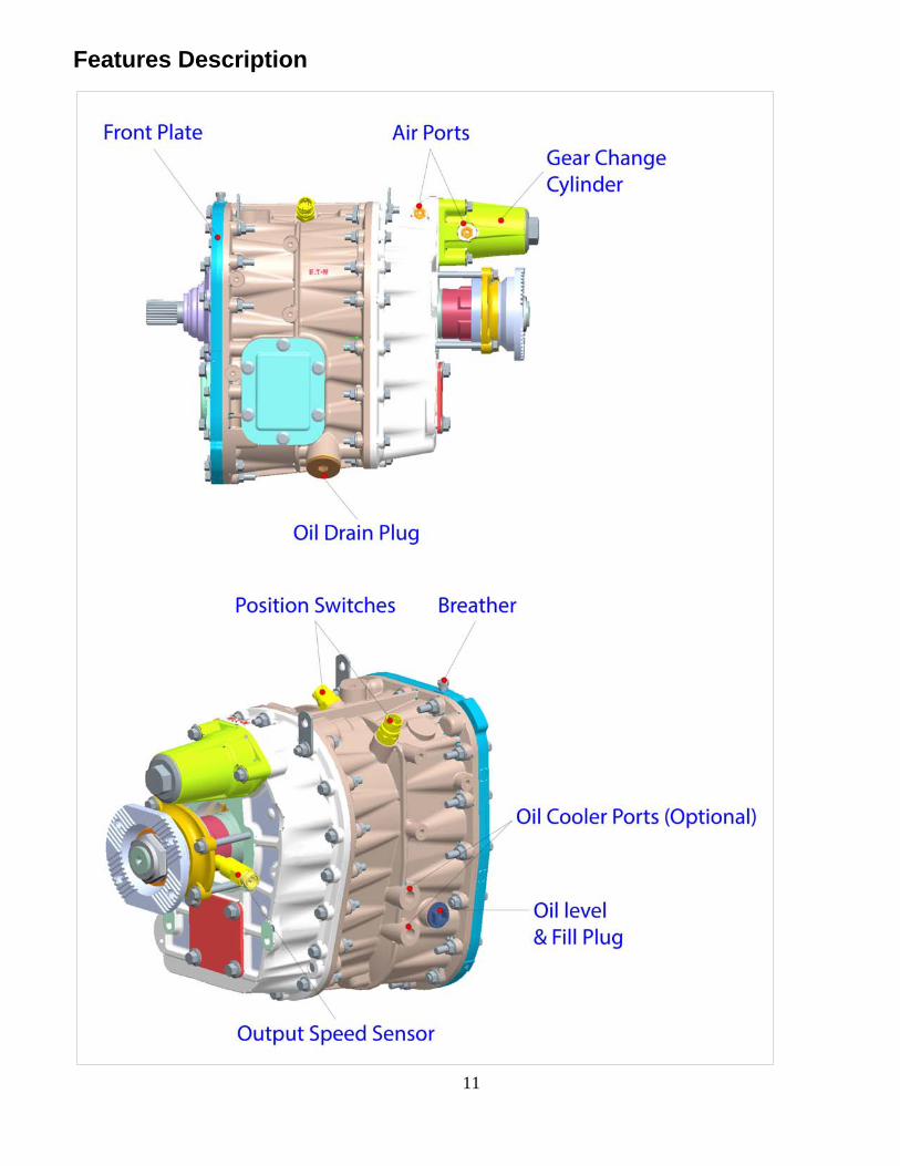
Features Description

12
Settings Values
Synchronizer Ring - Flange, Clearances, mm
Range
Minimum 0.50
Maximum (for ref) 2.16
Oil Pump
Oil Muff Sealing Rings Clearances, mm
Minimum 0.2
Oil Pump Clearances, mm
Outer Rotor to Pump Body 0.50 (maximum)
Inner to Outer Rotor 0.50 (maximum)

13
Disassembly precautions and inspection of expendable parts
It is assumed in the detailed disassembly instructions that the lubricant has been drained and the necessary linkage and air lines have been removed from the chassis. Follow each procedure closely in each section, making use of both the text and the pictures.
Cleanliness - Provide a clean place to work. It is important that no dirt or foreign material enters the unit during repairs. The outside of the unit should be carefully cleaned before starting the disassembly. Dirt is abrasive and can damage bearings.
1. Assemblies - When disassembling the various assemblies, such as the mainshaft, range change epicyclic and layshaft, place all parts on a clean bench in the same sequence as removed. This procedure will simplify Assembly and reduce the possibility of losing parts. When pulling off synchronizer hubs follow the procedures detailed in 'Disassembly’ using a suitable press of adequate capacity. Failure to adhere to the recommended procedures may cause irreparable damage. 2. Snap rings - Remove snap rings with pliers designed for this purpose. New selective fit snap rings must be fitted as specified in ''Assembly”. 3. Bearings - Carefully wash and re-lubricate all bearings as removed and protectively wrap until ready for use. Remove bearings with pullers designed for this purpose. 4. When pressing - Apply force to shafts, housings etc. with restraint. Movement of some parts is restricted. Do not apply force after the part being driven stops solidly. Use soft hammers for all disassembly work. Do not use pry bars or chisels to separate casing halves and housings or irreparable damage may be caused. Before assembling the transmission, the individual parts should be carefully checked and any that are damaged should be rejected. These should be renewed. This inspection procedure should be carefully followed to ensure the maximum wear life from the rebuilt unit. The cost of a new part is generally a small fraction of the total cost of downtime and labour. The use of a questionable part may make additional repairs necessary before the next regularly scheduled overhaul. Recommended inspection procedures are set forth in the following check list:
A. Bearings
1. Wash all bearings in clean solvent. Check rollers and races for pits and spalled areas. Renew damaged bearings. 2. Lubricate undamaged bearings and check for axial and radial clearances. Renew bearings with excessive clearances. 3. Check fits of bearings in housing bores. If outer races turn too freely in the bores, the housing should be renewed. Check housing bores for signs of wear prior to taking this action. Renew housing if wear is seen as a result of bearing spin (see Item L). 4. Planet gear bearings consist of two tracks of 18 loose assembled rollers, i.e. 36 rollers per gear, separated by a spacer. If any rollers in a gear set are worn or damaged the whole set must be renewed.
14
B. Gears
1. Check gear teeth for pitting of the tooth faces. Gears with pitted teeth should be renewed. 2. Check the internal bearing surfaces for wear or the effects of overheating. 3. Check axial clearances of gears. Where excessive clearance is found, check gear, ring and hub for excessive wear. Maintain the specified axial clearance on mainshaft forward gears. C. Synchronizer Assemblies
1. Check to ensure all splines are free from excessive wear. 2. Check that the engagement dog teeth on the sliding sleeves, synchronizer flanges and synchronizer rings are free from chipping and burring. 3. Check that the synchronizer ring cones are not excessively worn or showing the effects of overheating. Check the clearance between the synchronizer ring and the synchronizer. 4. Renew the springs, plungers and rollers. D. Splines
1. Check splines on all shafts for wear. If synchronizer hubs, output drive flange or clutch hub have worn into the sides of the splines, the shafts in this condition must be renewed. E. Thrust Washers
1. Check surfaces of all thrust washers. Washers scored, burnt or reduced in thickness should be renewed.
F. Range Change Planet Gears, Spindles and Needle Roller Bearings
1. If it is found necessary to dismantle the planet gears, retain each gear, spindle, rollers, spacers and washers in their respective set for Assembly in the same relative positions. 2. If uneven wear is found in the planet gears, check lubrication holes for blockage and renew all rollers. 3. Renew planet spindle grub screws on Assembly. G. Bearing Covers
1. Check covers for wear from thrust. Renew covers worn or grooved from thrust of bearing outer race. 2. Check bores of covers for wear. Renew those worn oversize. H. Oil Return Threads and Seals
1. Check oil seal in front bearing cover for damage and wear, renew if necessary. 2. Check oil seal in speedometer housing for damage or wear, renew if necessary. 3. Check oil seal tracks for wear and renew if worn or grooved. 4. Check the oil sealing rings in the muff ring for wear or breakage. I. O-Rings
1. Renew all O-rings. J. Oil Pump
1. Check the oil pump rotors and covers for scoring and wear. The complete pump assembly must be renewed if scored or excessively worn, or its serviceability is suspect in any way.

15
Assembly precautions
Make sure that interiors of all housings are clean. It is important that dirt be kept out of transmission during assembly. Dirt is abrasive and can damage polished surfaces of bearings and washers. Pay attention to certain precautions, as listed below, during assembly.
1. Gaskets - Use new gaskets where detailed only (neutral detent and remote control housing covers). All other locations, ensure mating faces are clean and undamaged and apply a continuous bead of recommended Loctite Sealant to one face only. Do not apply excessive sealant or allow it to penetrate into the bearings. 2. Capscrews - Use thread sealant on all capscrews. The corresponding torque ratings are to be found in 'Torque Tightening Recommendations'. 3. O-Rings - Lubricate all O-rings lightly with silicone lubricant. 4. Initial Lubrication - Lubricate bearings with gearbox oil during assembly. 5. Axial Clearances - Maintain the end floats of mainshaft gears as detailed in the chart on the following page. 6. Bearings - Use of the correct special tools and bearing drivers is recommended for the installation of bearings. Heating the bearing inner tracks where instructed will aid installation. 7. Output Shaft Drive Flange - Tighten the nut to the correct torque. Do not under any circumstances use an impact wrench to tighten the flange/yoke nut. Use only a hand operated torque wrench or a stall torque motor. Failure to carry out these instructions can cause damage to the locking medium of the nut.
During disassembly and again during assembly prior to tightening the new nut, it is important to ensure that the output shaft does not slide through the bearing, or the assembled range change synchronizer roller, plungers and springs may be displaced.
A suitable spacer should be temporarily assembled under the nut to allow for the thickness of the nut locking insert to ensure the shaft is firmly held in the bearing until the nut can be torque tightened.
8a. Synchronizer Hubs - Range synchronizer hub and must be heated to approximately 85°C before installation. Press fully home and hold under pressure for a short period to prevent creep while cooling.
8b. All synchronizer flanges to be lubricated before assembly.
9. Sun Gear - The sun gear is interference fit on the mainshaft splines and must be heated to approx. 130°C - 150°C (266°F - 302°F) before installation.

16
Lubrication recommendations
The following is the recommended lubricant. SAE 50 Eaton PS-164 approved.
Recommended Lubricants
Eaton does not approve mineral oil lubricants by brand name. Additives or friction modifiers which are not part of the original lubricant are not recommended. Lubrication Information Proper lubrication procedures are the key to a good all-around maintenance program. Eaton Transmissions are designed so that the internal parts operate in an oil circulating bath created by the motion of the gears and shafts. All parts will be properly lubricated if these procedures are closely followed:
1. Maintain oil level. Inspect regularly. 2. Follow maintenance interval chart. 3. Use the brand recommended by the truck manufacturer.
Maintain Proper Oil Level Make sure oil is level with the filler opening. Being able to reach oil with your finger does not mean oil is at proper level. Never mix different brand of oils. Operating Temperature It is important that the transmission operating temperature does not exceed 120°C (250°F) for an extended period of time. Operating temperatures above 120°C (250°F) cause breakdown of the oil and shorten transmission life. The following conditions in any combination can cause operating temperatures of over 120°C (250°F):
1. Operating consistently at road speeds under 32 km/h (20m.p.h.) 2. High engine RPM 3. High ambient temperature 4. Restricted air flow around transmission 5. Exhaust system too close to transmission 6. High horsepower, over-drive operation 7. High power PTO operation for extensive periods while stationary
High operating temperatures may require more frequent oil change.

17
Maintenance Interval Chart Oil change interval 300.000km or 3 years at vocational bus application Required Lubricant
Type Grade (SAE)
Gear Oil SAE50 Eaton PS 164
The use of lubricants not meeting these requirements will affect warranty coverage. Buy from a reputable dealer. Transmission Operating Angles Transmission operating angle up to 20 deg (18% road slope at transmission installation angle 9.8 deg)
* Refer OEM recommendatations for oil change / maintenance intervals.

18
Lubrication checking procedure
Oil Level Before checking the oil level or refilling, ensure vehicle is on level ground. Make sure that the oil is level with the filler opening. Draining Oil Drain transmission while oil is warm. To drain oil remove the drain plug at the bottom of the case, or Remove strainer from the intermediate case (see below). Clean the drain plug before refitting. Before draining the oil, ensure that oil is warm and the vehicle is on level ground. To drain the oil, remove the drain plug from the left hand side bottom of the intermediate case. Before refilling the transmission:
1. Remove and clean the oil strainer. Clean the strainer in kerosene (paraffin) or suitable solvent and dry thoroughly. Renew the washer and the O-ring if necessary. When refitting, tighten to the torque (40 to 47 Nm).
2. Dry the strainer thoroughly.
3. Clean the drain plug.
4. Inspect the washer and replace if necessary Before checking the oil level or refilling, ensure that:
1. Vehicle is on level ground. 2. Lubricant temperature is between 20°C and 50°C. 3. Lubricant is at the level of the filler plug hole opening.
The oil drain intervals should be as per the OEM recommendation. Refill the oil to the level of the filler opening. During oil refill, do not overfill. This causes the oil to be forced out of the front and rear seals. Do not mix different types of oil. While adding the oil it is recommended that different types and brands of oil are not intermixed because of possible incompatibility.
Do not overfill, this causes oil to be forced out of the front and rear seals.

19
Operating Temperature It is important that the transmission operating temperature does not exceed 120°C for an extended period of time. Operating temperatures above 120°C cause breakdown of the oil and shorten the transmission life. The following conditions can cause operating temperatures over 120°C:
1. Operating consistently at road speeds under 32 km/hour. 2. High engine RPM. 3. High ambient temperature. 4. Restricted air flow around transmission. 5. Exhaust too close to transmission. 6. High power PTO operation for extended periods
Towing
Before towing the vehicle, place the transmission in neutral, and lift the rear wheels off theground, or remove the axle shafts, or disconnect the driveline to avoid damage to the transmission during towing.
20
Power flow
21
Air System
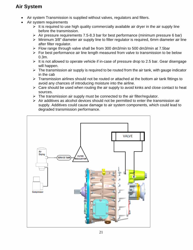
Air system Transmission is supplied without valves, regulators and filters. Air system requirements
It is required to use high quality commercially available air dryer in the air supply line before the transmission.
Air pressure requirements 7.5-8.3 bar for best performance (minimum pressure 6 bar) Minimum 3/8” diameter air supply line to filter regulator is required, 6mm diameter air line
after filter regulator. Flow range through valve shall be from 300 dm3/min to 500 dm3/min at 7.5bar For best performance air line length measured from valve to transmission to be below
0.3m. It is not allowed to operate vehicle if in-case of pressure drop to 2.5 bar. Gear disengage
will happen. The transmission air supply is required to be routed from the air tank, with gauge indicator
in the cab Transmission airlines should not be routed or attached at the bottom air tank fittings to
avoid any chances of introducing moisture into the airline. Care should be used when routing the air supply to avoid kinks and close contact to heat
sources. The transmission air supply must be connected to the air filter/regulator. Air additives as alcohol devices should not be permitted to enter the transmission air
supply. Additives could cause damage to air system components, which could lead to degraded transmission performance.

22

23
Loctite locations
24
Sr. No.
DescriptionTool Number
Illustration Use
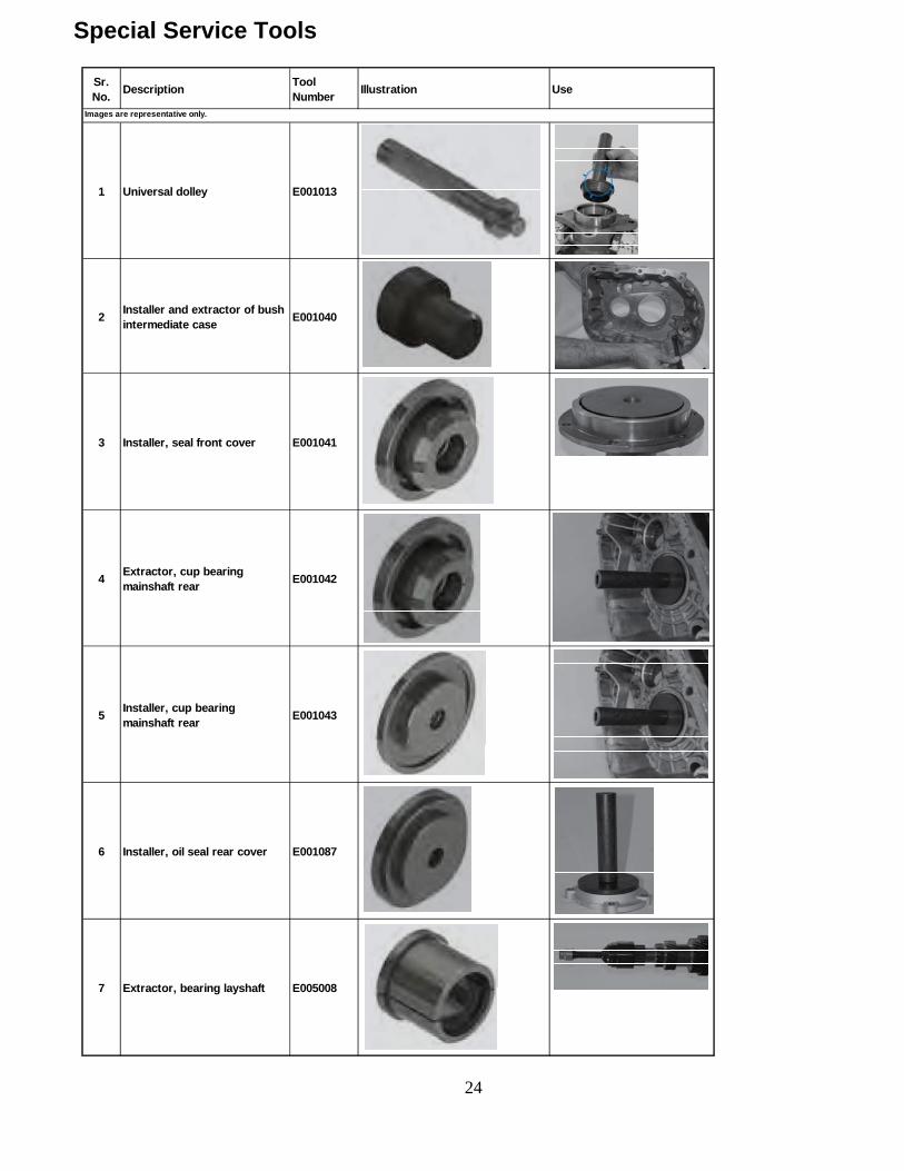
1 Universal dolley E001013
2Installer and extractor of bush intermediate case
E001040
3 Installer, seal front cover E001041
4Extractor, cup bearing mainshaft rear
E001042
5Installer, cup bearing mainshaft rear
E001043
6 Installer, oil seal rear cover E001087
7 Extractor, bearing layshaft E005008
Images are representative only.
Special Service Tools

25
Sr. No.
DescriptionTool Number
Illustration Use
8 Installer, bearing layshaft E010008
9Device for loosening the flange nut
E008005
10 Universal Extractor E012001
11 Extractor, bush E005009
12 Support for handling E014031
13 Extractor, bearing rear cover E014032
14 Sun gear retainer E014033
15 Jaws for Universal Extractor E014034
Images are representative only.

26
Section 2 - Main Transmission Overhaul
27
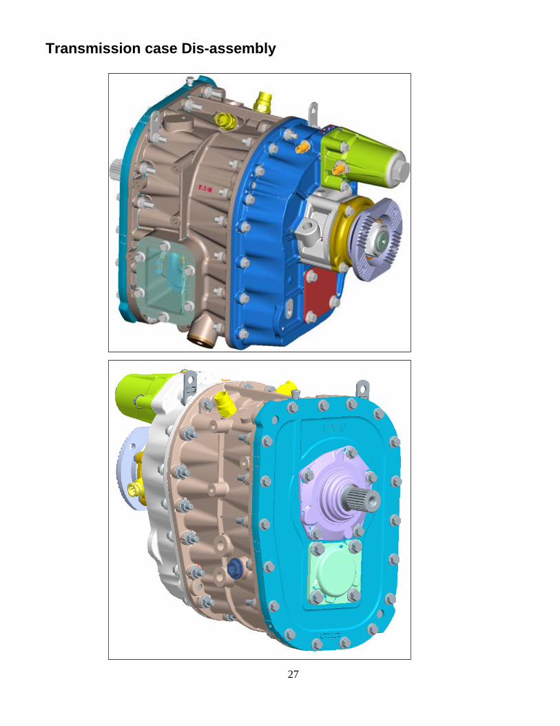
Transmission case Dis-assembly
28
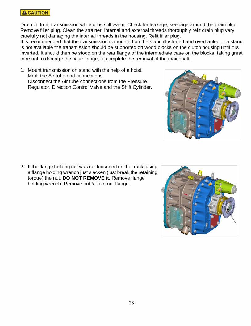
Drain oil from transmission while oil is still warm. Check for leakage, seepage around the drain plug. Remove filler plug. Clean the strainer, internal and external threads thoroughly refit drain plug very carefully not damaging the internal threads in the housing. Refit filler plug. It is recommended that the transmission is mounted on the stand illustrated and overhauled. If a stand is not available the transmission should be supported on wood blocks on the clutch housing until it is inverted. It should then be stood on the rear flange of the intermediate case on the blocks, taking great care not to damage the case flange, to complete the removal of the mainshaft. 1. Mount transmission on stand with the help of a hoist.
Mark the Air tube end connections. Disconnect the Air tube connections from the Pressure Regulator, Direction Control Valve and the Shift Cylinder.
2. If the flange holding nut was not loosened on the truck; using a flange holding wrench just slacken (just break the retaining torque) the nut. DO NOT REMOVE it. Remove flange holding wrench. Remove nut & take out flange.

29
3. Remove drain plug. Drain gear oil from the transmission while the oil is still warm. Clean the threads in the housing and on the plug. Wash or replace the strainer. Inspect and replace the washer if necessary.
4. Remove the range and neutral switched. Collect detent balls from each of the two bores. Use a magnet or tap the case gently to release the balls if necessary.
5. Remove speedo sensor.

30
6. Rotate transmission on stand to bring rear end up.
7. Remove capscrews and nuts securing rear case to intermediate case.
8. Attach a sling to output flange. With a hoist lift rear case gently as vertical as possible to separate rear case from intermediate case.
Note: Use soft mallet to separate the Rear Case from the Intermediate Case, if necessary. WARNING: Do not use pry bars or screw drivers as the case contact surfaces may get scratched.
31
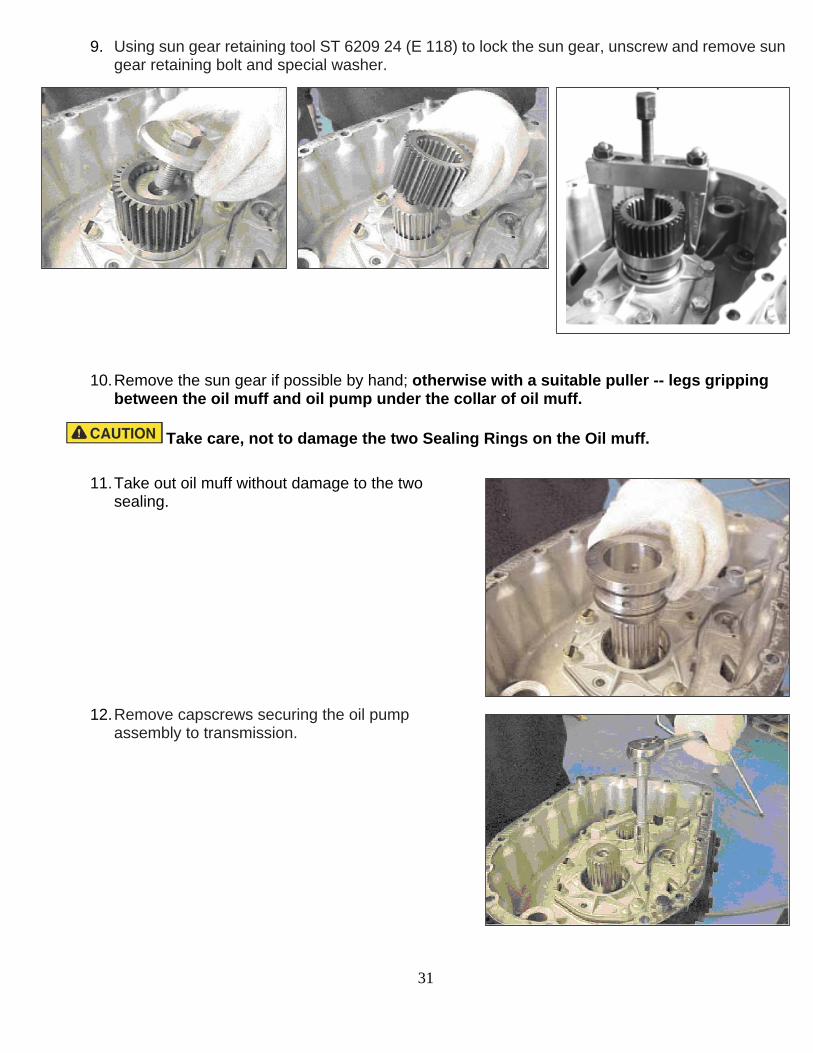
9. Using sun gear retaining tool ST 6209 24 (E 118) to lock the sun gear, unscrew and remove sun gear retaining bolt and special washer.
10. Remove the sun gear if possible by hand; otherwise with a suitable puller -- legs gripping between the oil muff and oil pump under the collar of oil muff.
Take care, not to damage the two Sealing Rings on the Oil muff.
11. Take out oil muff without damage to the two sealing.
12. Remove capscrews securing the oil pump assembly to transmission.

32
13. Using pry bar under the lugs or a lever through the
Drain plug bore, lift the Oil pump from the locating dowels and take out pump assembly.
14. Collect range change interlock pin located
in the bore between the selector rods, using a magnet if necessary.
33
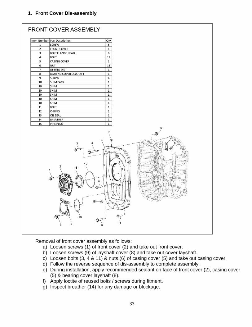
1. Front Cover Dis-assembly
Removal of front cover assembly as follows: a) Loosen screws (1) of front cover (2) and take out front cover. b) Loosen screws (9) of layshaft cover (8) and take out cover layshaft. c) Loosen bolts (3, 4 & 11) & nuts (6) of casing cover (5) and take out casing cover. d) Follow the reverse sequence of dis-assembly to complete assembly. e) During installation, apply recommended sealant on face of front cover (2), casing cover
(5) & bearing cover layshaft (8). f) Apply loctite of reused bolts / screws during fitment. g) Inspect breather (14) for any damage or blockage.

34
2. Intermediate case Dis-assembly
a) Remove bearing (3) from mainshaft (4) with the help of suitable puller. b) Pull out gear mainshaft (5) from mainshaft , and then take out mainshaft. c) Take out rear bearing (6) from housing. d) Take out bearing cup & cone (12), gear layshaft (2) from layshaft (1). e) Now take out layshaft and rear cup & cone (12). f) Check the condition of case bush for any wear / damage, remove and replace with new one if
required. g) Follow the reverse sequence of dis-assembly to complete assembly. h) Install gears (5 & 2) with suitable press on mainshaft & layshaft respectively. i) Install front & rear bearings on the layshaft with the help of suitable press.

35
3. Rear case Dis-assembly
a) Support the rear case assembly on a suitable clean block, keeping the planet carrier assembly
downwards. Remove the bolts (15) from the range cylinder (9).
b) Take out rod spring range (14) and take out compression springs (12 & 13) alongwith its retainers after circlips removal (10).
c) Remove piston range cylinder (5) & bush (3); check the condition of O-ring (2, 4, 6, 7 & 8) of piston & bush.
d) Take out bush (3).

36
e) Remove the output flange retaining nut (18) alongwith spacer (33) and tap drive flange out (using a suitable puller if available) – the flange outer diameter is a tight fit in the ball bearing.
Note the flange boss fits in the bearing inner race.
Note: The rear case must not be knocked or allowed to move relative to the output shaft while the nut is being removed or after the nut has been removed; the range change synchronizer sleeve may be displaced and the rollers, plungers (and likely springs) may fall out.
f) Slide the rear case out from the output shaft and the Range shaft.
g) Remove the range fork from the sliding sleeve. Separate the range change selector rod by drifting out the grooved pin (dowel) with a pin punch.
h) Remove speedo rotor.

37
i) Remove the synchronizer ring low.
j) Make identification marks on the sliding sleeve in line with the plungers, springs and rollers. Place the planetary assembly on wooden block and remove the annulus with sliding sleeve. To separate the annulus from the sliding sleeve, insert a rivet or steel pin of 2.0-2.3 mm diameter and 10 mm length, in 3 holes in the annulus. Tighten a large hose clip around the rivets or pins to compress the inside snap ring in the sliding sleeve. Slide the sliding sleeve out from the annulus.
k) Remove the snap ring securing the synchronizer hub bearing to the output shaft. Remove the
rollers, plungers and springs from the synchronizer hub.

38
l) Invert the assembly and drop the end of the shaft onto a stout wood block to shock the hub, synchronizer ring high and fixed hub range off the shaft.
m) Invert the assembly. Remove the snap ring securing synchronizer flange - high to the planet carrier.
n) Remove the synchronizer flange - high.

39
Synchronizer Ring- Flange, Clearance (mm)
Minimum 0.50
Maximum (Ref) 2.16
o) Remove the socket headed countersunk screws and retainers holding the synchronizer flange - low to the rear case.
p) Lift out the reaction plate and the synchronizer flange.
q) Lift out the reaction plate and the synchronizer flange.

40
r) Lift the spacer ring and take it out.
s) If necessary remove the snap ring from the synchronizer flange.
t) Remove four capscrews retaining the oil seal cover and output shaft bearing housing, remove oil seal cover. Note its orientation.
u) Remove bearing housing, tapping it sideways.
v) Drive bearing out, if necessary, of housing using a drift.
41
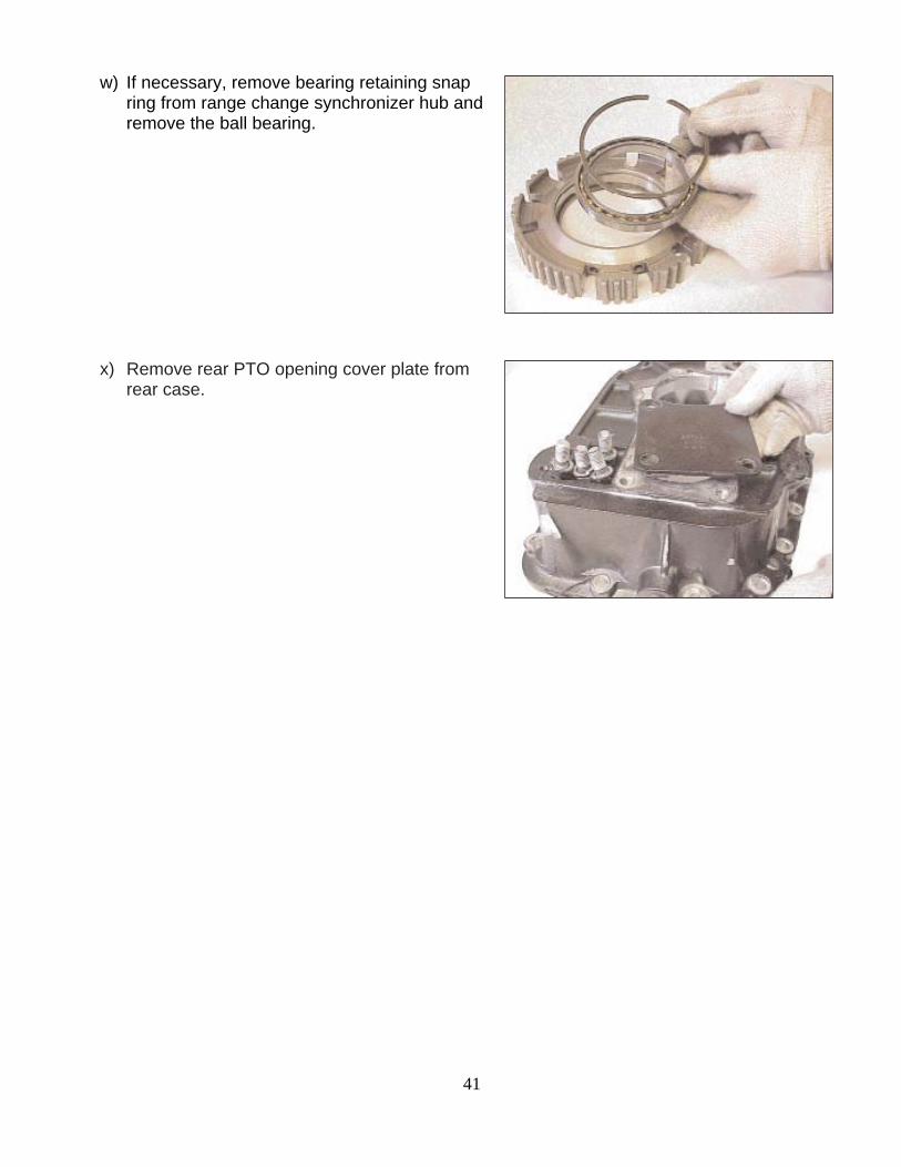
w) If necessary, remove bearing retaining snap ring from range change synchronizer hub and remove the ball bearing.
x) Remove rear PTO opening cover plate from rear case.
42
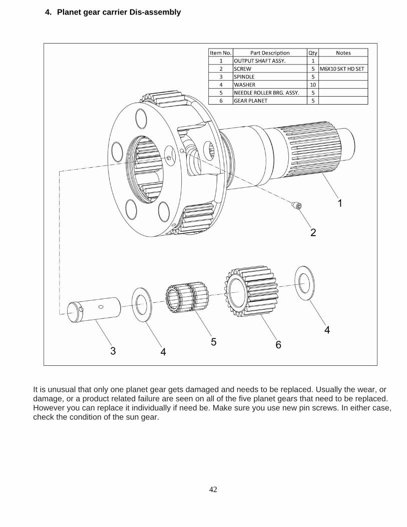
4. Planet gear carrier Dis-assembly
It is unusual that only one planet gear gets damaged and needs to be replaced. Usually the wear, or damage, or a product related failure are seen on all of the five planet gears that need to be replaced. However you can replace it individually if need be. Make sure you use new pin screws. In either case, check the condition of the sun gear.

43
a) Remove the bearing spindle retaining screws (Allen key 3 mm) from the planet gear carrier. The screws are locked by deforming the screw top. So a very little portion at the top of the head of grub screw has to be drilled (preferably a flat drill) out before the screw can be removed.
b) Using a soft faced mallet and a drift drive the bearing spindle out of the carrier in the direction shown.
Note that the spindle has a step. The spindle can be driven out only one way.
c) Slide the gear, bearing rollers, spacers and thrust washers out of the carrier. Repeat these operations for the other four gears.

44
5. Planet gear carrier Assembly
a) Place one thrust washer on a flat plate (if using old
washer, grooved side up). Apply petroleum jelly to it.
b) Place the gear on the thrust washer. Apply petroleum jelly to the bore of the gear.

45
c) There are 36 rollers. Place 18 rollers into position.
d) Place the spacer above the rollers.
e) Insert the 18 rollers above the spacer and then insert the washer. Place the thrust washer.
(old washer-worn side down).
f) Support the planet carrier on the work bench such that the output shaft is down and slide the assembled gear into position in the carrier.

46
g) Slide in the gear assembly until the bore of the planet carrier and gear assembly align.
h) Ensure the locating hole in the spindle aligns with the hole in the carrier. Drive the spindle into carrier using a soft faced mallet.
Note: There is a lubrication hole directly opposite the locating hole. Align both the holes correctly - lubrication hole towards the center and locating hole away from the center.
i) Ensure the threads are clean and dry. Install a new locking grub screw, using thread locking sealant Loctite 270. Tighten to 5 - 8 N m and peen the head with a punch or drift. Repeat the operations for remaining four gears.

47
6. Rear Case Piston & Range Cylinder Assembly
a) Range change selector rod bush - rear case. Drift out the rear bush complete with carrier from the rear case.
b) Install a new O-ring into the groove on the outer periphery of the bush carrier. Lubricate it sparingly with silicone grease.
c) Install the bush until the O-ring has just entered the case. Wipe off any excess grease and apply sealer (Loctite 641) around the exposed part of the bush carrier. Drive it into casing using special tool.
d) Install a new O-ring into the range change selector rod rear bush carrier. Lubricate with silicone grease.

48
e) Assemble O-ring (1) on bush, O-ring (3, 5 & 6) in piston (4); lubricate O-ring with silicone grease.
f) Place O-ring on range cylinder; lubricate O-ring with silicone grease.
g) Assemble range cylinder as per below steps:
I. Install a new O-ring (11) in plug (12), lubricate O-ring with silicone grease. II. Now place rod spring range (7) on to piston. III. Fit the circlip (6) on rod (7). IV. Fit the retainer (5) on rod spring range (7), spring (4 & 3) and then retainer (2) and finally fit
the circlip (1). V. Install the mounting bolts of cylinder range (8), tighten to specified torque.
VI. Fit the elbow (10).

49
7. Rear Case Assembly a) Insert selector rod through range change selector fork (flat face of
fork and threads of shaft on the same side). Rotate the rod to align the holes (two slots in the rod to right).
b) Align retaining pin holes so that with threaded end of selector
shaft to the left, the interlock detents face you. Install a new grooved pin.
c) Install snap ring into the range change synchronizer hub
and place the bearing into hub against snap ring.
d) Install second snap ring to retain bearing in hub.

50
e) Stand the annulus assembly, sliding sleeve up, on a bench. Fit the snap ring in the external groove on synchronizer sleeve. Insert the sliding sleeve, pressing the snap ring in the sleeve groove all around, in the annulus aligning it so that snap ring ends DO NOT come on any hole on the periphery of the annulus.
f) Push the sleeve into the annulus until the snap ring expands into the annulus locking the two parts together. If necessary, use a hose clip to compress the snap ring uniformly all around.
g) Stand output shaft assembly on a firm support or a block about 100 mm thick. Place the synchronizer flange over the locating splines. Install retaining snap ring.
h) Place the synchronizer ring over the synchronizer flange.
Press the cone firmly down. With feeler gauges measure the clearance between the ring and the flange. Renew the flange and the ring if the clearance is less than the minimum specified. Lubricate synchronizer ring and flange.

51
i) Place synchronizer hub and bearing assembly onto the
shaft aligning the slots in the hub with the shoulders on the synchronizer ring. Use a soft mallet and drift or mandrel to ensure the bearing is fully home against the stop.
j) Install retaining snap ring.
k) Apply grease to 9 springs and put one spring and plunger each in nine slots. Mark one flat internal tooth on shifting sleeve as shown. Sliding sleeve up, align the annulus coinciding the mark with one central slot and slide the assembly over the planet gears.
l) Lift up annulus and support it by about 15 mm thick piece. Ensure the plungers and the springs are fully inside the holes in all the six slots and no plunger projects out of spring. Snap one roller with grease applied to it, by hand between the plunger head and sliding sleeve, each into the six outer slots (two outer of each set of three slots) - in the synchronizer hub.
52
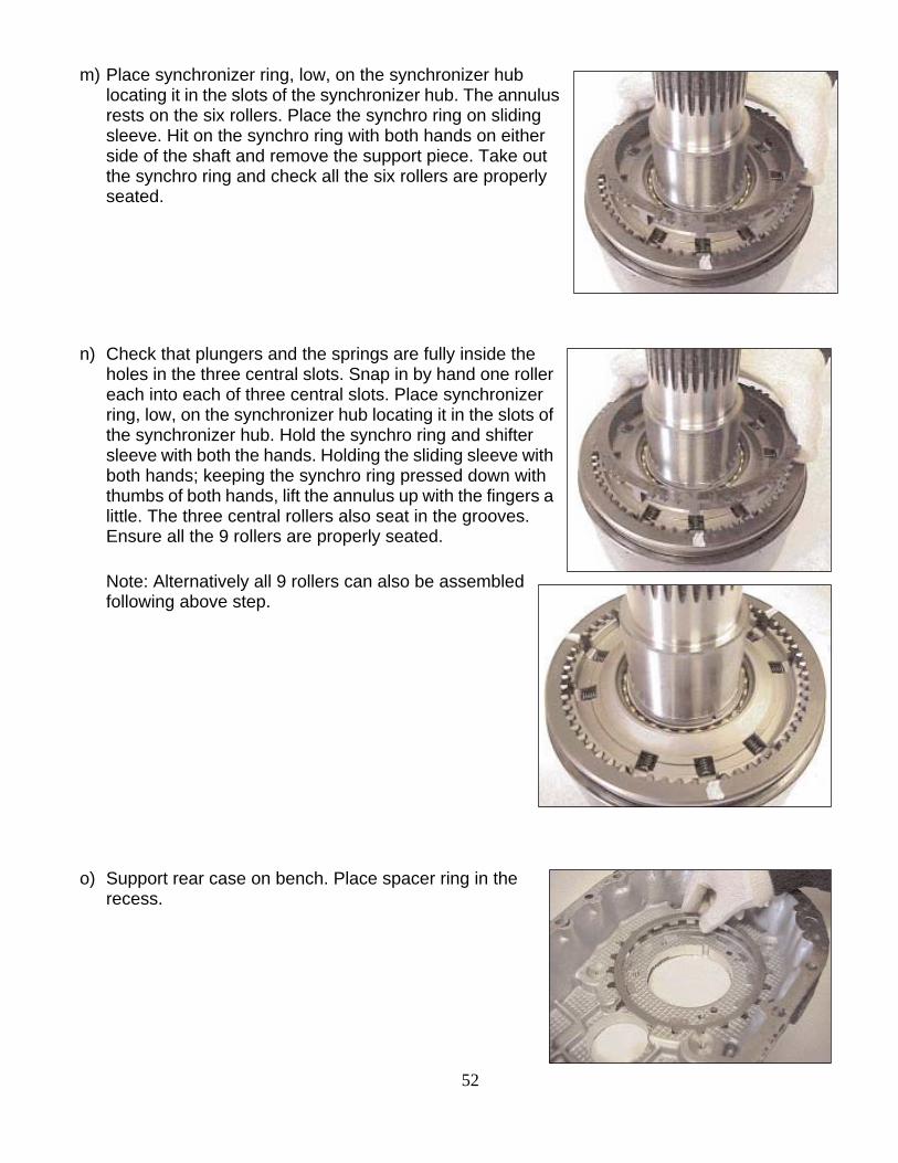
m) Place synchronizer ring, low, on the synchronizer hub locating it in the slots of the synchronizer hub. The annulus rests on the six rollers. Place the synchro ring on sliding sleeve. Hit on the synchro ring with both hands on either side of the shaft and remove the support piece. Take out the synchro ring and check all the six rollers are properly seated.
n) Check that plungers and the springs are fully inside the holes in the three central slots. Snap in by hand one roller each into each of three central slots. Place synchronizer ring, low, on the synchronizer hub locating it in the slots of the synchronizer hub. Hold the synchro ring and shifter sleeve with both the hands. Holding the sliding sleeve with both hands; keeping the synchro ring pressed down with thumbs of both hands, lift the annulus up with the fingers a little. The three central rollers also seat in the grooves. Ensure all the 9 rollers are properly seated.
Note: Alternatively all 9 rollers can also be assembled following above step.
o) Support rear case on bench. Place spacer ring in the
recess.

53
p) Install the large circlip into the outer peripheral groove
on synchronizer flange, low.
q) Place synchronizer flange, low, (with the snap ring) in the rear case bore.
r) Place reaction plate (rounded edges of internal splines and teeth towards flange) over synchronizer flange.
s) Install the three retaining plates and countersunk head screws. Tighten screws to 27 – 30 N m.

54
t) Place Planet Carrier and Annulus Assembly, rear end up, on table. Locate selector fork and shaft assembly into synchronizer sleeve, threaded end of shaft up. Support shaft under its bottom end to prevent its tilting while installing the rear case over it.
u) Ensure that the O-ring in selector shaft bush is in position, lubricate it with silicone grease. Invert the partly assembled rear case, and place it over the output shaft aligning the selector shaft through the bush.
v) Place speedo rotor (teeth up) over output shaft.
w) Install output shaft bearing in bearing housing using a soft faced mallet and a suitable tool.

55
x) Install a new oil seal into the carrier using special tool.
y) Apply sealant Loctite 5900 to the face either of the baring housing or rear case. Place the bearing housing assembly over the shaft and tap the bearing inner race all around till the bearing housing touches the rear case.
z) Apply sealant Loctite 5900 to the face of the bearing housing and carrier with oil seal fitted in it.

56
aa) Apply thread sealant Loctite 243 to the cap screws,
four, and tighten them to 35 – 39 N m.
bb) Smear grease on the inner periphery of the oil seal and install the output drive flange.
Note: Coupling flange fits inside the bearing inner race).Fit temporarily (to be removed later) the old nyloc nut (nylon insert sheared) to tighten the coupling flange tight enough so range hub rollers do not slip out.
Note: The output shaft must not be knocked or driven inwards while the nut is loosened or removed; the range change synchronizer sleeve may be displaced and the rollers, plungers and springs fall out of the hub.
cc) Apply Loctite 5900 sealant and fit the PTO opening cover. Tighten to 69 – 78 N m.
57
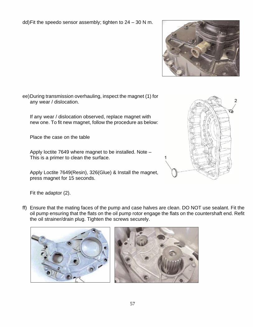
dd) Fit the speedo sensor assembly; tighten to 24 – 30 N m.
ee) During transmission overhauling, inspect the magnet (1) for any wear / dislocation.
If any wear / dislocation observed, replace magnet with new one. To fit new magnet, follow the procedure as below:
Place the case on the table
Apply loctite 7649 where magnet to be installed. Note – This is a primer to clean the surface.
Apply Loctite 7649(Resin), 326(Glue) & Install the magnet, press magnet for 15 seconds.
Fit the adaptor (2).
ff) Ensure that the mating faces of the pump and case halves are clean. DO NOT use sealant. Fit the oil pump ensuring that the flats on the oil pump rotor engage the flats on the countershaft end. Refit the oil strainer/drain plug. Tighten the screws securely.

58
gg) If necessary install new sealing rings on oil muff if the rings are excessively worn or scored. Lubricate oil muff and locate it on the rear of mainshaft. Compressing sealing rings push oil muff into pump.
hh) Install sun gear onto the mainshaft if it was removed by hand; otherwise heat the sun gear (130 -150 deg C) and then install on the mainshaft.
ii) Place retaining washer against the sun gear and fit a new patchlock retaining cap screw.
jj) Using special tool to lock the sun gear, tighten the capscrew to 225 -255 N m.

59
kk) Apply sealant to intermediate case rear flange in a
continuous bead around the flange and the retaining cap screw holes.
ll) Install detent plunger, spring and ball using a magnet if necessary.
mm) Fit the range & reverse switch alongwith balls & o rings. nn) Fit drain & filler plug.
oo) Support rear case assembly with a suitable sling and hoist as illustrated keeping the shaft as vertical as possible.
pp) Lower the rear case over the intermediate case ensuring that the range change selector rod aligns with the bush in the intermediate case. Rotate the output flange slightly to aid alignment over the sun gear if necessary.
qq) Install mainshaft & layshaft assembly.

60
rr) Install front cover assembly & casing cover as below procedure:

61
Install front cover assembly as follows:
a) During installation, apply recommended sealant on face of front cover (2), casing cover (5) & bearing cover layshaft (8).
b) Apply loctite of reused bolts / screws during fitment. c) Apply oil to O-ring before fitment inside the casing cover. d) Install the casing cover (5) on intermediate case & tighten with the mounting screws &
nuts as per the specified torque. e) Install the oil seal into front cover with the
help of suitable tool.
f) Apply recommended sealant on front cover face & install front cover assembly on casing cover, and tighten the screws (1) of front cover (2) to the specified torque.
g) Apply recommended sealant on layshaft cover face & install the layshaft cover (8) on casing cover, and tighten the screws (9) to the specified torque.
h) Install lifting eye at proper place. i) Connect the Air tube connections from the Pressure Regulator, Direction Control Valve
and the Shift Cylinder.

Copyright Eaton, 2016. Eaton hereby grant their customers, vendors, or distributors permission to freely copy, reproduce and/or distribute this document in printed format. It may be copied only in its entirety without any changes or modifications. THIS INFORMATION IS NOT INTENDED FOR SALE OR RESALE, AND THIS NOTICE MUST REMAIN ON ALL COPIES.
Note: Features and specifications listed in this document are subject to change without notice and represent the maximum capabilities of the software and products with all options installed. Although every attempt has been made to ensure the accuracy of information contained within, Eaton makes no representation about the completeness, correctness or accuracy and assumes no responsibility for any errors or omissions. Features and functionality may vary depending on selected options.