eba allgemein ultimate tb 2kanal en - racechip in the “fine-tuning the racechip” section...
TRANSCRIPT

Item number: EBA-ALLG-ULTIMATE-TB-K2-GER-V1
RaceChip Ultimate Installation Guide
Turbo petrol 2-Channel
Test winner, September 2013

Foreword ...........................................................................................................................................................................................4Scope of delivery .................................................................................................................................................................5Installation .....................................................................................................................................................................................6First steps for installing the RaceChip ................................................................................................................................................6
Removing the engine cover .....................................................................................................................................................................8
Connecting to sensor ................................................................................................................................................................................9
Connecting the RaceChip to a wiring harness ..............................................................................................................................16
Fastening the RaceChip ........................................................................................................................................................................17
Completing the installation ..................................................................................................................................................................19
Troubleshooting ................................................................................................................................................................20Fine-tuning of the RaceChip ............................................................................................................................22Index of plugs .......................................................................................................................................................................25Contact us ..................................................................................................................................................................................28
Contents

Page 4
Foreword
Dear customer,
Finally - you are now the proud owner of a new RaceChip Ultimate! In just a few minutes you will experience the tremendous driving pleasure that RaceChip offers.
Regardless of whether you are on bending country roads, accelerating away at traffi c lights or coasting on motorways, your RaceChip is guaranteed to thrill! The “RaceChip Effect” allows a completely new dimension of driving pleasure, as your vehicle gives you performance the like of which you have never experienced before. And you are not alone! Every year we welcome over 100,000 new RaceChip enthusiasts across the world. Our top priority is to offer you the best performance enhancements for your vehicle – with the best technology and quality standards.
Your feedback helps us to become even better. We would be thrilled to hear about your new driving experiences with RaceChip.
So start looking forward to your fi rst drive with your new RaceChip. After installing you can begin straight away.
Happy driving.
Your RaceChip Team
Individually customised for your vehicle
Quality & technology Made in Germany
Optimisation within power reserves
Comprehensive product guarantee
GERMANY

Page 5
RaceChip Ultimate Individually customised for your vehicle.
• Deactivation plug for resetting your vehicle to its factory settings
• Cable tie for fastening the RaceChip and wiring harness in your engine bay
• Torx key in case you wish to open the RaceChip.
• Installation guidefor installing your new RaceChip in just a handful of stepsIf they are available, we will send you additional vehicle images for the installation process via e-mail.
Scope of delivery
Wiring harness Automobile-grade, suitable for your vehicle (1)
Other equipment
(1) Picture may differ from delivered product.

Page 6
First steps for installing the RaceChipInstallation
Open your vehicle’s bonnet and close and lock the doors. For vehicles with a keyless system: please place the key outside the radio reception range of the vehicle (to be on the safe side, at a distance of 10 metres).
After locking the vehicle, wait another 10 minutes. This ensures that there is no residual electrical voltage in the engine bay connections and that the signal flow in the engine ceases.10 min
Generally speaking, you do not require special tools to perform the installation. However, a simple wire cutter is useful for the purposes of removing excess material from the cable tie once the installation is complete.
In the following section we explain how to install your RaceChip using an example engine. If your engine has a different design, individual engine parts may be arranged differently in the engine compartment when compared to the images here. However, the parts that are relevant for the Race Chip are largely the same.
Before installing the RaceChip, please first wait for your engine to cool down. Otherwise there is a risk of sustaining burns.

Page 7
RaceChip wiring harness
A B
cable with disconnected series plug
manifold absolute pressure connection
RaceChip Ultimate
RaceChip Ultimate
turbo boost pressure-connection
Installed RaceChip
Setup illustration
This is how the RaceChip looks in its fi nal installed position. We will now explain step-by-step how to install it.
turbo boost pressure-connection
manifold absolute pressure connection

Page 8
Remove the engine cover from the holding clips and place it next to the car. You must jiggle the cover slightly to release it from the holding clips. If there is no cover on your engine, you can proceed directly to step 2.
Removing the engine cover
Step 1 of 12
Removing a bolted engine cover
In some vehicles it is necessary to loosen one or more bolts before you can remove the engine cover.

Page 9
Step 2 of 12
Connecting to sensor
This image shows the connections that are relevant for the installation in your vehicle.
Transverse engine
turbo boost pressure-connection
manifold absolute pressure connection
It may be the case that the engine of your vehicle is not longitudinal, as shown in step 2, but rather transverse. In this case you must apply the steps of the installation instructions to the type of engine you have. The installation steps remain the same.
Please check your e-mail inbox. If available, we will send you additional vehicle images for the installation via email.

Page 10
Lokalisieren Sie zunächst den Ladedruck-Anschluss in Ihrem Motorraum (Abbildung unten).
Step 3 of 12
A
Setup illustration
cable coming from the RaceChip Ultimate
cable with disconnected series plug
turbo boost pressure-connection
turbo boost pressure-connection
turbo boost pressure-connection

Page 11
Step 4 of 12
Now remove the plug from the connection socket by gently pressing the locking plug (see image below).
The plugs are locked into the connection sockets by means of a locking clip. Press the locking clip and pull the plug.
Because the plug is often connected very tightly to the socket, it is helpful, when pressing the locking clip, to fi rst push the plug towards the connection socket before subsequently pulling on it.
In addition, temperature fl uctuations in the engine bay can result in a type of “vacuum effect” between the plug and the socket. This can be solved by lightly “wiggling” the plug.
Please note that there may be different versions of the installed connection plug. If the plug shown here does not correspond to the plug in your car, you will fi nd a list of other plugs on page 25 with tips on how they can be removed.
Locking clip

Page 12
Now connect the part of the RaceChip wiring harness marked “A” to both the disconnected series plug and the socket in your vehicle. Make sure that the plug’s locking clip engages again.
Step 5 of 12

Page 13
Once the connection to the turbo boost pressure is complete, it is time to make the connection to the manifold absolute pressure. To begin, locate the manifold absolute pressure in your engine bay (see image below).
Step 6 of 12
Setup illustration
B
manifold absolute pressure connection
manifold absolute pressure connection
manifold absolute pressure connection
cable coming from the RaceChip Ultimate
cable with disconnected series plug

Page 14
Now remove the plug from the connection socket by gently pressing the locking plug (see image below).
Step 7 of 12
The plugs are locked into the connection sockets by means of a locking clip. Press the locking clip and pull the plug.
Because the plug is often connected very tightly to the socket, it is helpful, when pressing the locking clip, to fi rst push the plug towards the connection socket before subsequently pulling on it.
In addition, temperature fl uctuations in the engine bay can result in a type of “vacuum effect” between the plug and the socket. This can be solved by lightly “wiggling” the plug.
Please note that there may be different versions of the installed connection plug. If the plug shown here does not correspond to the plug in your car, you will fi nd a list of other plugs on page 25 with tips on how they can be removed.
Locking clip

Page 15
Now connect the part of the RaceChip wiring harness marked “B” to both the disconnected series plug and the socket in your vehicle. Make sure that the plug’s locking clip engages again.
Step 8 of 12
Page 16
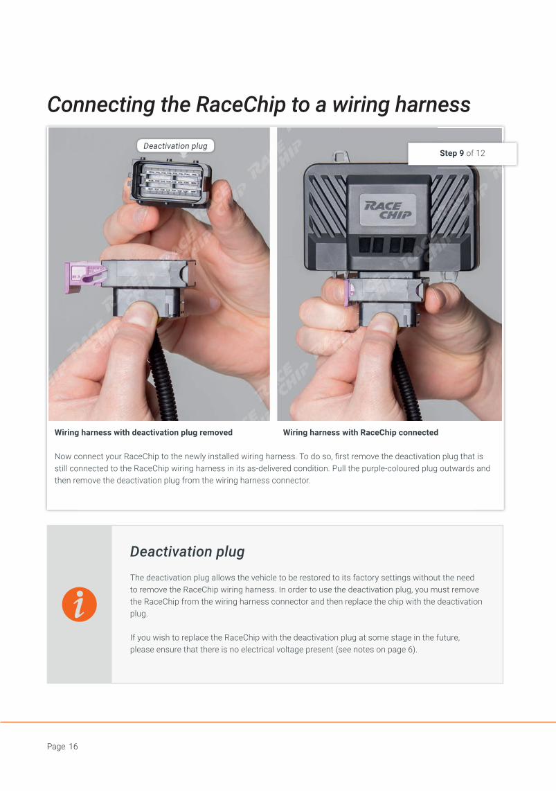
Now connect your RaceChip to the newly installed wiring harness. To do so, fi rst remove the deactivation plug that is still connected to the RaceChip wiring harness in its as-delivered condition. Pull the purple-coloured plug outwards and then remove the deactivation plug from the wiring harness connector.
Connecting the RaceChip to a wiring harness
Step 9 of 12
Wiring harness with deactivation plug removed Wiring harness with RaceChip connected
Deactivation plugThe deactivation plug allows the vehicle to be restored to its factory settings without the need to remove the RaceChip wiring harness. In order to use the deactivation plug, you must remove the RaceChip from the wiring harness connector and then replace the chip with the deactivation plug.
If you wish to replace the RaceChip with the deactivation plug at some stage in the future, please ensure that there is no electrical voltage present (see notes on page 6).
Deactivation plug

Page 17
Fastening the RaceChip
• When selecting a fastening point, make sure that the RaceChip is protected from exposure to water, heat, and vibrations.
• Do not wrap the RaceChip in an airtight bag as this can lead to a built up of condensation.
When searching for a secure fastening point for the RaceChip, make sure that the wiring harness can be properly routed in the engine bay in the next installation step. The harness must not, for instance, be routed along engine parts that become very hot, nor should the harness be routed under tension. Fasten the RaceChip in place using the supplied cable tie, as illustrated in the image above.
Step 10 of 12

Page 18
Route the cable along a suitable path (for example, along an existing harness) and then fasten it using the supplied cable tie. Using a wire cutter, you can remove the excess length of the cable tie.
• Do not route the cable in areas in your vehicle that become overly hot during operation (e.g. the exhaust system, turbocharger, etc.).
• Do not route the cable along movable parts (e.g. fan belts, cam belts, fan wheels).
• Never fasten the cable onto hoses (e.g. a brake hose) as this could result in abrasion.
Step 11 of 12
Page 19
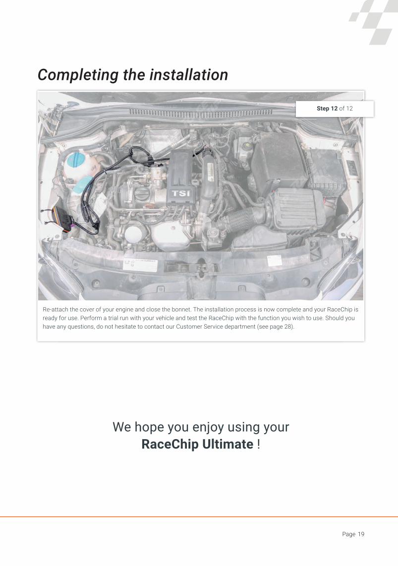
Completing the installation
We hope you enjoy using your RaceChip Ultimate !
Step 12 of 12
Re-attach the cover of your engine and close the bonnet. The installation process is now complete and your RaceChip is ready for use. Perform a trial run with your vehicle and test the RaceChip with the function you wish to use. Should you have any questions, do not hesitate to contact our Customer Service department (see page 28).

Page 20
Troubleshooting
No performance boost - I am not satisfied with the performance level of my vehicle.
You have the option of individually customising your RaceChip’s performance level. It is possible, for example, to increase or decrease the performance boost. To do this, you need to adjust the rotary switch inside the RaceChip. A detailed functional description and the exact location of the switch can be found in the “Fine-tuning the RaceChip” section (starting on page 22). However, it is important to note that our chips are always shipped with what we consider to be the ideal fine-tuned setting for your engine.If, after further fine-tuning, you still do not notice a performance boost, then please contact our Customer Service department.
Jolting - My vehicle jolts after the installation of the RaceChip
It is possible to further customise your RaceChip to the special characteristics of your engine. This involves an additional installation step (see “Fine-tuning”, page 22 onwards).If this does not rectify the problem, please provide our Customer Service staff with an exact description of the driving circumstances in which the problem arises. The Customer Service department will then suggest further adjustments for solving the issue.
An engine indicator lamp lights up - After the installation of the RaceChip, an engine indicator lamp lights up (fail-safe/fault signal)
Firstly, a lit engine indicator lamp does not necessarily mean that something is wrong with your engine. This may be a protective measure designed by the manufacturer. There can be several different causes of an illuminated fault signal once the engine has been started. However, the RaceChip cannot independently bring about this type of fault signal. When the engine is started or at idle speed, the performance boost itself is not active. This type of fault can be the result of a sensor being disconnected while the control unit is active. Please consult the information on page 6.
If there is a recurring fault signal, starting and restarting the engine several times may solve the problem. If the engine indicator lamp lights up after a period of driving, please contact our Customer Service staff.
If, after the installation, your RaceChip does not function as desired, the following list serves as a set of troubleshooting tips.

Page 21
The vehicle does not start - After the installation of the RaceChip, the vehicle’s ignition does not work
Please make sure that you have installed the chip in accordance with this guide. If you are not able to find the cause of the fault, please contact our Customer Service staff.
No noticeable fuel savings - I do not notice any fuel savings
Please compare the before-and-after levels of fuel consumption based on the vehicle’s actual consumption – the on-board computer often displays incorrect values. It is important that you do not inappropriately adjust your driving style as a result of the RaceChip performance boost, i.e. by accelerating more frequently. If the fuel savings provided by the RaceChip in its as-delivered condition are not satisfactory, please contact our Customer Service staff for a fine-tuning adjustment.

Page 22
Rotary switch S2
Rotary switch S1
S2 S1
Fine-tuning of the RaceChip
Your RaceChip is shipped with optimisation software and a chosen factory setting that are customised to your vehicle’s engine. In its as-delivered state, the RaceChip guarantees optimum customisation of your vehicle software in line with the RaceChip’s own software and also provides the following advantages: a considerable performance boost within the vehicle’s existing reserves, a long engine service life and fuel savings.
Nevertheless, manufacturer-based production tolerances may have an effect. In order to compensate for these tolerances, there is a rotary switch inside the RaceChip that allows for additional fi ne-tuning of the RaceChip.
Exemplary factory adjustment: B-1Exemplary factory adjustment: B-1Exemplary factory adjustment: B-1Exemplary factory adjustment: B-1
DB1S2 S1
Example calculation:
RaceChip UltimateRotary switch position: B1Cable reference: DM-A3001
1
Rotary switch
T10 Torx key
Opening the RaceChip
To open the RaceChip (if necessary), a T10 torx key is included in the scope of delivery (see image). Using this key, unfasten the six screws on the underside of the RaceChip. You can now open the housing.
How do I fi nd the factory setting?
Your bill includes a reference to the factory setting installed in your shipped RaceChip. The factory setting for your vehicle is designated as “B1”. The “D” is not signifi cant.

Page 23
RaceChip UltimateRotary switch position: B1Cable reference: DM-A3001
Adjusting the performance boostIf you fi nd that the achieved performance boost does not quite live up to your expectations, it can be tuned further using the rotary switch. Only perform this tuning if the achieved performance boost at the factory setting does not meet your expectations for the engine. Please adjust the performance in incremental steps, starting with Tuning 1. As soon as the desired performance boost has been achieved, stick with this tuning. If your engine begins to jolt while running, then select a lower tuning.
Factory adjustment Tuning 1 Tuning 2 Tuning 3
S2 S1 S2 S1 S2 S1 S2 S1
B 1 C 1 D 1 E 2
2 1 3 1 4 1 5 1
9 1 A 1 B 1 C 1
6 1 7 1 - - - -
4 1 5 1 6 1 7 1
3 1 4 1 5 1 6 1
5 1 6 1 7 1 - -
C 1 D 1 E 1 F 1
F 1 0 1 1 1 2 1

Page 24
Factory adjustment Tuning 1 Tuning 2 Tuning 3 Tuning 4
S1 S2 S1 S2 S1 S2 S1 S2 S1 S2
B 1 8 1 9 1 A 1 - -
2 1 E 1 F 1 0 1 1 1
9 1 8 1 - - - - - -
6 1 2 1 3 1 4 1 5 1
4 1 0 1 1 1 2 1 3 1
3 1 F 0 0 1 1 1 2 1
5 1 1 1 2 1 3 1 4 1
C 1 8 1 9 1 A 1 B 1
F 1 B 1 C 1 D 1 E 1
0 1 C 1 D 1 E 1 F 1
If the installation of the RaceChip results in jolting or if an engine indicator lamp lights up, smooth operation of the engine can be restored by using a suitable fi ne-tuning adjustment. Please proceed in incremental steps, as illustrated below. First, set the rotary switch to Tuning 1 and start your vehicle’s engine. If your engine is running as smoothly as you would like and no engine lamps light up, then begin increasing the setting with the rotary switch, starting with Tuning 2. Perform a test drive each time you go up a tuning level. If the engine does not run as desired at a particular tuning level, then go down a level. This level is then the ideal setting for obtaining a performance boost based on the special characteristics of your engine.If your engine does not run as you would like in any tuning setting, or if an engine indicator lamp lights up in service mode, please contact our Customer Service staff.
Improving smoothness of engine operation
Page 25
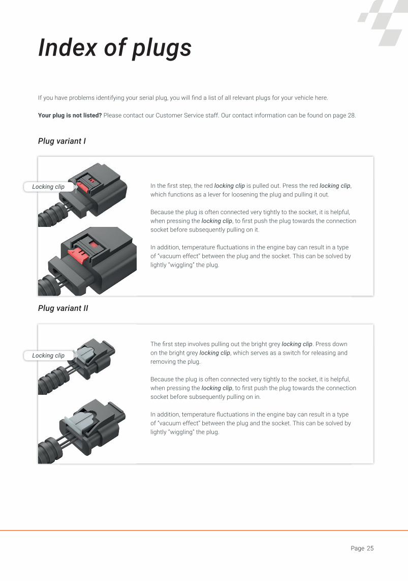
Index of plugs
If you have problems identifying your serial plug, you will fi nd a list of all relevant plugs for your vehicle here.
Your plug is not listed? Please contact our Customer Service staff. Our contact information can be found on page 28.
The fi rst step involves pulling out the bright grey locking clip. Press down on the bright grey locking clip, which serves as a switch for releasing and removing the plug.
Because the plug is often connected very tightly to the socket, it is helpful, when pressing the locking clip, to fi rst push the plug towards the connection socket before subsequently pulling on in.
In addition, temperature fl uctuations in the engine bay can result in a type of “vacuum effect” between the plug and the socket. This can be solved by lightly “wiggling” the plug.
Plug variant I
Plug variant II
Locking clip In the fi rst step, the red locking clip is pulled out. Press the red locking clip, which functions as a lever for loosening the plug and pulling it out.
Because the plug is often connected very tightly to the socket, it is helpful, when pressing the locking clip, to fi rst push the plug towards the connection socket before subsequently pulling on it.
In addition, temperature fl uctuations in the engine bay can result in a type of “vacuum effect” between the plug and the socket. This can be solved by lightly “wiggling” the plug.
Locking clip

Page 26
Your notes

Page 27

Page 28
Contact us
Normal landline and mobile phone charges apply. Contact us at:+49 (0) 7023 - 77 999 - 0
Our service hotline is available from:
Monday to Friday, from 8:30am to 12:30pm and from 2:30pm to 5:30pm.
Please have your customer details ready when you call. This allows us to access your key data quickly, and to help you as fast as possible.
We are always here to help!
RaceChip Chiptuning GmbH & Co. KGUlmer Straße 12373037 GöppingenGermany
Umsatzsteuer (VAT) Identifi cation number: DE 260672432 Registered at the District Court of Ulm: HRA 721734 Tax number: 63079/11153 Personally liable partner: RaceChip Chiptuning Verwaltungs GmbH Chief Executives: Manuel Götz, Dominic Ruopp, Dr. Daniel Appelhoff, Dirk Bongardt Head offi ce: Ulmer Straße 123, 73037 Göppingen, GermanyRegistered at HRB District Court, Ulm: HRB 724254
You can also get in touch using our contact form:
www.racechip.de/kontakt
Imprint