ebook1 an introduction_to_3_d_scanning_en_26082014
TRANSCRIPT

AN INTRODUCTION TO 3D SCANNING

While the mainstream media continues its obsession with 3D printing, another quiet, perhaps more impactful, disruption is revolutionizing the way products are designed, engineered, manu-factured, inspected and archived. It’s 3D scanning -- the act of capturing data from objects in the real world and bringing them into the digital pipeline.
ACCORDING TO A RECENT STUDY BY MARKETSANDMARKETS, THE 3D SCANNING MARKET WILL GROW NEARLY
15%ANNUALLY OVER THE NEXT FIVE YEARS, WITH THE PORTABLE 3D SCANNING SEGMENT LEADING THE WAY.
Portable 3D scanning is fueling the movement from the laboratory to the front lines of the factory and field, driven by the following key factors:
PLM)

3D scanners are tri-dimensional measurement devices used to capture real-world objects or environments so that they can be remodeled or analyzed in the digital world. The latest generation of 3D scanners do not require contact with the physical object being captured.
3D scanners can be used to get complete or partial 3D measurements of any physi-cal object. The majority of these devices generate points or measures of extremely high density when compared to traditional “point-by-point” measurement devices.
Real Object 3D Model

OBJECTS ARE USUALLY SCANNED IN 3D FOR
2 PURPOSES:
CAD
CAICAE
Reverse engineering
Inspection
PART SCAN
GEOMETRICALENTITIES
2D COMPARISON
CAD
3D COMPARISON
MESH

There are TWO major categories of scanners based on the way they capture data:

Scanning results are represented using free-form, unstructured three-dimensional data, usually in the form of a point cloud or a triangle mesh. Certain types of scanners also acquire color information for applications where this is important.
Images/scans are brought into a common reference system, where data is merged into a complete model. This process -- called alignment or registration -- can be performed during the scan itself or as a post-processing step.
Point Cloud
Triangle mesh

The resulting triangle mesh is typically exported as an STL (STereoLithography or Standard Tessellation Language) ) surfaces for CAD modeling.
Triangle Mesh exportable in STL format
Converted to NURBS surfaces

THE BENEFITS AND LIMITATIONS OF A 3D SCANNER ARE TYPICALLY DERIVED FROM ITS POSITIONING METHOD. THAT’S WHY IT IS VALUABLE TO TAKE A LOOK AT POSITIONING METHODS WITHIN THE DIFFERENT 3D SCANNER CATEGORIES.
The main 3D scanner categories:

Limitations
CMMs (coordinate measuring machines) and measuring
probe heads. It is also possible to mount a 3D scanning head on a CMM.
POSITIONING METHOD: MECHANICAL ENCODERSCMMs with portable arms are positioned using the mechanical encoders integrated in the arm.
Advantages

Limitations
Optical tracking devices can track various types of measurement tools, including the positioning of a 3D scanner.
POSITIONING METHOD: EXTERNAL OPTICAL TRACKING DEVICEThese scanners use an external optical tracking device to es-tablish positioning. They usually use markers (such as passive or active targets) that optically bind the tracking device to the scanner.
Advantages

Limitations
These scanners project a pattern of light onto a part and process how the pattern is distorted when light hits the object. Either an LCD projector or a scanned or diffracted laser beam projects the light pattern. One or two (sometimes more) sensors record the projected pattern.
POSITIONING METHOD: OFFLINE TARGET POSITIONING AND GEOMETRY POSITIONINGThe scanner can either rely solely on the part geometry to posi-tion the data or rely on positioning targets (small stickers provided with the system that can be placed directly on the part) to align 3D data.
If only one camera is used, the position of the projector in relation to the camera must be determined in advance; if two cameras are used, the stereoscopic pair must be calibrated in advance.
Advantages

Limitations
Many types of portable 3D scanners are available on the market today, principally using laser-line or white-light technologies.
Laser scanners project one or many laser lines on an object while white-light devices project a light and shade pattern. Both will analyze the resulting deformed projections to extract the 3D data.
POSITIONING METHOD: REAL-TIME SELF-POSITIONING THROUGH POSITIONING TARGETS, OBJECT’S NATURAL FEATURES/TEXTURES OR HYBRIDHandheld scanners rely on two cameras to create what is called stereoscopic vision. This enables the device to de-
which could be positioning targets, the object’s natural features or textures. Some newer portable scanners use a mix of positioning types called hybrid positioning.
Advantages

3D scanning has emerged as a critical tool in every step of the product lifecycle management (PLM) process. This is especially true of the new generation of truly portable, self-positioning scanners.
The ability of 3D scanning to bridge the gap between physical objects in the real world and the digital de-sign environment has become extremely valuable in a wide range of industries that use PLM -- aerospace, automotive, consumer products, manufacturing, and heavy industries among the principal ones.
improved quality, reduced warehousing costs, and better understanding of product performance.
In the pages that follow, we’ll explore
different stages of PLM:

3D scanning is used in the concept stage of PLM for a wide variety of processes, including determining
Concept
Concept design Concept prototyping
– Competitive product analysis
– Measurement of product environmentor connecting/Surrounding parts
– Measurement of existing parts for aftermarket or custom equipment
– Clay model measurement/Reverse engineering
– Models and mock-upsmeasurement/Reverse engineering
– Styling and aesthetics
– Integration of prototype
– Form study, proof-of-concept prototypes
– Ergonomy prototypes

“ Our research units include nearly 2,000 researchervs with experimental facilities.”
Midwestern Manufacturing produces sideboom pipelayer attachments for new and old tractors from
industry leaders such as Caterpillar, John Deere, Case and Komatsu. When 3D models are not available,
Midwestern uses reverse engineering to capture a tractor and create a fully integrated sideboom.
The ability to quickly create a detailed, accurate model of the tractor jump-starts the design process
and enables Midwestern to reduce product development time.
“ The detailed 3D scans and 3D model allow us to accurately design and
integrate our sideboom attachment onto the existing platform (tractor),”
says the vice president of engineering for Midwestern.
“ accurate considerably minimizes the
make to the platform. It also allows us to completely visualize the design
”Midwest
pipelayer attachindustry leaders suc
and Komatsu. WheMidwestern uses reve
tractor and create a f
The ability to quickly create model of the tractor jump-starts th
and enables Midwestern to dev
aoom.
, accuratesign process
reduce productelopment time.
D model design and hchment onto
form (tractor),””resident of engineering
for Midwestern.
onsiderably minimizes the
the platform. It also allows us o completely visualize the design
””
develo

3D scanning is used in the design stage of PLM for computer-aided design (CAD); rapid prototyping; and test-ing, simulation and analysis (CFD, FEA).
Design
CAD design Prototyping Testing, simulation and analysis
–
– Reverse engineering(extracting design-intent)
– Packaging design
– Rapid prototyping/Manufacturing
–
– Prototype inspection
–
– Interference analysis
–

“ Our research units include nearly 2,000 researchervs with experimental facilities.”
manufacturer of customized parts and vehicles that specializes in styling, engineering, CAD, FEA, manufac-
turing, CNC machining, binding and welding.
A motorcycle chassis is very complex and features irregular shapes; as a result, the conventional methods
tedious. Having no access to manufacturers’ 3D drawings, a powerful reverse engineering solution was
needed to reduce the production times of CAD drawings.
3D scanning makes it possible to easily and rapidly obtain a highly accurate 3D images of the assembly and
all of the existing components at the same time—without having to draw them in 3D. The engineering
they previously spent on CAD drawings and the reverse engineering process. The use of a self-positioning hand-
held laser scanner right in the shop played a key role in Zeel Design being able to drastically reduce design
project turnaround times.
irregu
tedidrawings, a p
needed to reduce
3D scanning makeobtain a highly accurate 3
all of the existing componenthaving to draw them
they previously spent on CAD drawiengineering process. The use of a self-p
held laser scanner right in the shop plain Zeel Design being able to drastically red
project turnaroun
ole esign
d times.
“ Considering how often we use our 3D scanner, and if we add up the work
hours that we are saving, we expect to get an excellent ROI very quickly.”- According to the president of Zeel Design

3D scanning is used in the manufacturing stage of PLM for applications such as tooling design, assembly and production, and quality control.
Manufacturing
Tooling design Assembly/Production Quality control
– Reverse engineering of dies, molds,
–tooling measurements
– Tooling validation/Inspection
–
–
–
–
–
– Supplier quality inspection

“ Our research units include nearly 2,000 researchervs with experimental facilities.”
The European Aeronautic Defense and Space (EADS) company, recently renamed Airbus Group, performs 3D
optical scans of tooling equipment to assess the pos-
(carbon/epoxy) parts as well as post-manufacturing deformation with parts/CAD comparisons.
First, EADS scans the tooling, in order to verify its compliance with the CAD plan. Then, parts manufac-
tured with this tooling are scanned, and the scanning
The second step consists of using very powerful simu-lation tools to estimate the distortion of the parts be-
of the manufacturing parts.
The versatility of a portable 3D scanner made it the tool of choice for this task, both in its capacity to scan
unorthodox shapes, handle hard-to-scan materials, such as composite parts, and perform scans directly
on the project’s site.
The secolation too
The versatility of atool of choice for this ta
unorthodox shapes, hsuch as composite parts, tly
site.
“ Thanks to its quick set up and acquisition, ease of use, measurement performance for many types of surface
states, and portability, the system enabled us to quickly scan the metallic
parts. The equipment’s portability made it possible for us to record the
measurements right at the manufacturing site.”
A member of the EADS Structure Health Engineering (NDT & SHM) Department
“ Our research units include nearly 2,000 researchervs with experimental facilities.”
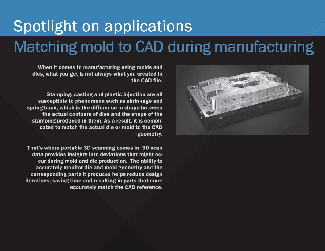
When it comes to manufacturing using molds and dies, what you get is not always what you created in
Stamping, casting and plastic injection are all susceptible to phenomena such as shrinkage and
spring-back, which is the difference in shape between the actual contours of dies and the shape of the
stamping produced in them. As a result, it is compli-cated to match the actual die or mold to the CAD
geometry.
That’s where portable 3D scanning comes in: 3D scan data provides insights into deviations that might oc-
cur during mold and die production. The ability to accurately monitor die and mold geometry and the
corresponding parts it produces helps reduce design iterations, saving time and resulting in parts that more
accurately match the CAD reference.
That’s wherdata provide
cur during maccurately moni
corresponding parts iterations, saving time an
accurately e.

3D scanning is used in the servicing stage of PLM for applications such as documentation; maintenance, repair and overhaul (MRO); and replacement, recycling and restoration of parts.
Servicing
Documentation Maintenance, repair andoverhaul (MRO) Replacement/Recycling
–parts/Tooling
–systems, serious gaming
–
– Wear and tear analysis
–
–
– Reverse engineering for developing replacement/Restoration parts
–

“ Our research units include nearly 2,000 researchervs with experimental facilities.”
Atlas Weyhausen, a manufacturer of wheel loaders and other heavy equipment, uses a portable 3D scan-
ner to measure components and equipment for quality assurance and for data feedback from prototype parts. The company saves time and money from the increas-
ing number of situations where components must be inspected at their installed location or recorded
abroad at the supplier’s location.
The steel construction of a new driver’s cab and vari-ous paneling sections have been digitized, for ex-
time for quality comparisons.
“ easy to see,”
says an Atlas quality assurance manager.
“ Freeform surfaces are easy to align,
the data feedback into our CAD system.”
To
asy to see,””surance manager.
are easy to align,
into our CAD system.””

3D scanning is used in digital reconstruction to capture an actual object or environment -- such as an historical artifact or a legacy product -- and reproduce it as ac-curately as possible for digital archiving, re-creation or preservation.
3D scanning is used in customized manufacturing to
existing consumer products, including toys, accessories and apparel.
Customization extends to capturing the human body
design.
A full range of applications can be found in the Creaform website.
Custo
design.
A full range of appCreaform website.

“ Our research units include nearly 2,000 researchervs with experimental facilities.”
Milwaukee School of Engineering’s (MSOE) Rapid Prototyping (RP) Center modeled a time capsule from
jug. The time capsule was a central part of Face Jugs:
exhibition that originated at the Milwaukee Museum of Art.
The original face jug -- about the size of a grapefruit -- would normally be covered in a powder to reduce the
done with a fragile, valuable piece.
containing target dots that served as reference points for the 3D scanner. Geomagic software was used to upsize the scan model and create the compartments
and other features of the time capsule.
electroplating.
-- wou
containing target dfor the 3D scanner.upsize the scan model
and other fe
ating.

This e-book provided you with a high-level overview of 3D scanning and a glimpse into the multitude of new possibilities and applications it enables in a variety of disciplines.
Most of the key developments in 3D scanning have come about in less than a decade. Indeed,3D scanning is a fast-growing discipline with tremendous potential in the future.
To explore a broader range of 3D scanning topics, we invite you to visit the applications section on www.creaform3d.com

15%15%1CAE
CMM

15%15%1
CAI

15%15%1

5825, rue Saint-Georges
www.creaform3d.com
Creaform Shanghai Ltd. 70# Building,No.1000 Zhang Heng Road,
Shanghai 201210 China
Meisenweg 37
Creaform France