ec type-approval certificate - cardinal scale · 2018-10-12 · annex page 2 of 14 ec type-approval...
TRANSCRIPT
DELTA
Venlighedsvej 4
2970 Hørsholm
Denmark
Tel. (+45) 72 19 40 00
Fax (+45) 72 19 40 01
www.delta.dk
VAT No. DK 12275110
EC Type-Approval Certificate
No. DK 0199.553
825
NON-AUTOMATIC WEIGHING INSTRUMENT
Issued by DELTA Danish Electronics, Light & Acoustics
EU - Notified Body No. 0199
In accordance with the requirements for the non-automatic weighing instrument of
EC Council Directive 2009/23/EC.
Issued to Cardinal Scale Manufacturing Company
203 East Daugherty
P.O. Box 151
Webb City, MO 64870
USA
In respect of Non-automatic weighing instrument designated 825 with variants of modules
of load receptors, load cells and peripheral equipment.
Accuracy class III and IIII
Maximum capacity, Max: From 1 kg up to 999,999 kg
Single interval or multi-interval
Verification scale interval: ei = Maxi / ni
Maximum number of verification scale intervals: ni = 10000 for class III,
ni = 1000 for class IIII (however dependent on environment and the compo-
sition of the modules).
Variants of modules and conditions for the composition of the modules are
set out in the annex.
The conformity with the essential requirements in annex 1 of the Directive is met by the ap-
plication of the European Standard EN 45501:2015 and OIML R76:2006.
The principal characteristics and approval conditions are set out in the descriptive
annex to this certificate.
The annex comprises 14 pages.
Issued on 2015-08-26
Valid until 2025-08-26 Signatory: J. Hovgård

Annex page 1 of 14 EC type-approval certificate no. DK 0199.553
Issued by DELTA
Descriptive annex
Contents Page
1. Name and type of instrument and modules 2
2. Description of the construction and function 2
2.1 Construction 2
2.2 Function 3
2.3 Available options 5
3. Technical data 6
3.1 Indicator 6
3.2 Load receptors, load cells and load receptor supports 6
3.3 Composition of modules 8
3.4 Documents 8
4. Interfaces and peripheral equipment 8
4.1 Interfaces 8
4.2 Peripheral equipment 8
5. Approval conditions 9
5.1 Measurement functions other than non-automatic functions 9
5.2 Application programs 9
5.3 Compatibility of modules 9
6. Special conditions for verification 9
6.1 Composition of modules 9
6.2 Application software 9
7. Securing and location of seals and verification marks 11
7.1 Securing and sealing 11
7.2 Verification marks 12
8. Location of CE mark of conformity and inscriptions 12
8.1 Indicator 12
8.2 Load receptors 12
9. Pictures 13
10. Composition of modules – an example 14

Annex page 2 of 14 EC type-approval certificate no. DK 0199.553
Issued by DELTA
1. Name and type of instrument and modules
The weighing instrument is designated Model 825, which is a system of modules consisting of an elec-
tronic indicator, connected to a separate load receiver and peripheral equipment such as printers or
other devices as appropriate. The instrument is a Class III or IIII, self-indicating weighing instrument
with single-interval or multi-interval and an internal AC mains power supply.
2. Description of the construction and function
2.1 Construction
2.1.1 Indicator
Technical specifications are according to Section 3.1.
2.1.2 Enclosure, keyboard and display
The Model 825 is housed in a stainless steel enclosure 305 mm wide x 247 mm high x 95 mm deep.
This enclosure can be mounted either on a vertical or horizontal surface and is designed to meet an
IP 66 rating. It is designed primarily for industrial use, but may also be used in an office environment.
The Model 825 keyboard contains 52 membrane keys along with multiple programmable soft keys
used to enter data and to control indicator functions.
The front panel of the indicator contains the keyboard and a display. The display consists of a 640 x
480 pixel matrix colour back lit LCD display. The display is 133 mm wide x 102 mm high and is
backlit.
The bottom panel of the indicator contains 6 gland connectors and one access panel:
1 gland connector for the power cord
2 gland connectors for the load cell input from the load receptors
3 gland connectors for I/O including digital isolated inputs and outputs and serial I/O
1 sealed access panel for access to Ethernet and USB connectors
(removal of this panel reduces the enclosure rating from IP 66 to IP 32)
Electronics
The Model 825 weight-indicating instrument in its basic configuration uses three separate printed cir-
cuit boards; a main pc board, an operator interface pc board, and a scale input pc board. These three
printed circuit boards contain all of the basic instrument circuitry. Additional option boards are availa-
ble. One option board provides an additional load receiver input allowing the addition of up to eight
more load receivers. The second option board can be one of several types that contain additional I/O
circuitry like serial interfaces or digital I/O circuitry. The weight-indicator will accept a maximum of
nine option boards in addition to the standard scale input board.
The main printed circuit board contains a total of ten I/O option board slots and handles the real time
scale tasks. This board contains a Freescale Coldfire MCF5213 32-bit 80 MHz processor with 32 Kb
of RAM, and 256 Kb of embedded flash memory. The operator interface board uses a Freescale Cold-
fire MCF5328 32-bit 240 MHz processor and handles the indicator’s operating system, display, and
graphic control functions. Included on this board are 32 Mb of RAM, 64 Mb of NAND flash memory,
and 32 Mb of programming NOR flash memory. Each scale input pc board contains a Freescale
MC9S08DZ 8-bit processor with 8 Kb of RAM, 60 Kb of flash, and 2 Kb of NOVRAM used for stor-
age of setup and calibration parameters. The power supply is a universal switching type and can accept
an input voltage of from 90 to 264 VAC 50 or 60 Hz. The indicator produces a load cell excitation
voltage of 10.8 VDC.

Annex page 3 of 14 EC type-approval certificate no. DK 0199.553
Issued by DELTA
2.1.3 Load receptors, load cells, and load receptor supports
Set out in Section 3.2.
2.1.4 Interfaces and peripheral equipment
Set out in Section 4.
2.2 Function
The Model 825 weight-indicating instrument is a microcontroller based electronic weight indicator
that requires the external connection of one or more strain gauge load cells. The weight information
appears in the digital display located on the front panel and may be transmitted to peripheral equip-
ment for recording, processing, or display. The indicator is powered from the power mains at 90 to
264 VAC 50 or 60 Hz.
The primary functions are described below:
2.2.1 Power-up
On power up the indicator will perform a display test then show the instrument model number fol-
lowed by the software revision level for three seconds. After that it will display the current weight us-
ing either the previously established zero reference or, if configured to do so, will automatically estab-
lish the current weight as a new zero reference.
2.2.2 Test function
On power up the indicator will test all memory functions followed by a display test. The display tests
consist of turning on all pixel elements for approximately one second followed by turning all of the
pixel elements off for approximately one second. At the conclusion of the display test, the indicator
displays the Cardinal logo and model number and software version. The test sequence may also be
manually initiated by pressing the ASTERISK key followed by pressing the UNITS key.
2.2.3 Display range
The indicator displays weight from –99,999e to Max +9e (gross weight) within the limits of the dis-
play capacity.
2.2.4 Zero setting
Pressing the ZERO key causes a new zero reference to be established and the zero annunciator to turn
on indicating the display is at the centre of zero.
Zero setting range: 4 % of Max.
Initial zero setting range: ≤20% of Max.
Zero setting can only take place when the load receptor is not in motion.
2.2.5 Zero tracking
The weight indicators is equipped with a zero-tracking feature, which operates over a range of 4 % of
Max and only when the indicator is at gross zero and there is no motion in the weight display.
2.2.6 Units
The UNITS key may be used to select the units in which the weight is displayed. The selected unit of
measure is indicated in the weight display. The Model 825 can be configured to display in units of
pounds, kilograms, grams, tonnes, ounces, and tons. A custom unit of measure can also be selected.
However, only kilograms, grams, and tonnes are allowed.
2.2.7 Tare
The weight indicator is provided with a semi-automatic tare and a keyboard preset tare feature.
Annex page 4 of 14 EC type-approval certificate no. DK 0199.553
Issued by DELTA
2.2.7.1 Semi-automatic tare
When the semi-automatic tare feature has been selected, pressing the TARE key will enter the current-
ly displayed weight value as the new tare weight value. The weight display will automatically change
to the net weight display mode and turn the NET annunciator on. This tare value can be cleared by
pressing the TARE key when there is no load on the load receptor. This tare entry cannot take place if
the load receptor is in motion or if a print operation is taking place.
2.2.7.2 Preset (numeric) tare
The preset or numeric tare feature allows the manual entry of a known tare value. Press the appropriate
numeric keys to enter the known tare weight then press the TARE key. When the TARE key is
pressed, the numeric value entered will be accepted as the new tare weight and the display will auto-
matically enter the net weight display mode as indicated by turning the NET annunciator on. The tare
value entered must agree with the verification scale interval, e.
2.2.8 Net / gross indication
Once a valid tare weight, other than zero, has been stored, the weight display can be switched from a
gross weight only display to a net weight display mode by pressing the NET / GROSS key. Each time
the key is pressed, the display will alternate between the net and gross display modes.
2.2.9 Printing
A printer may be connected to the selected serial data port. In the net display mode, the gross, tare and
net weights to the printer each time the PRINT key is pressed. In the gross mode, only the gross
weight is transmitted. The time and date and identification, if selected, will also be transmitted. It is
also possible to include additional data in the form of customer name or number on the printed record.
The print will not take place if the load receptor is not stable, if the gross weight is less than zero, if
the weight exceeds Max or during data entry from the keyboard.
2.2.10 Display test
A self-test routine is initiated by pressing the ON / OFF key to turn the instrument off then pressing it
again to turn the instrument ON or by pressing the ASTERISK key then pressing the UNITS key. The
test routine consists of turning on all of the pixel elements in the display for approximately one second
followed by turning them all off for approximately one second. After that, the Cardinal logo is dis-
played along with the model number of the indicator and the software version.
2.2.11 Time and date
The Model 825 weight indicator is equipped with a time and date feature. To view and / or reset the
time and date, press the TIME / DATE key. The time and date settings can be viewed and / or reset us-
ing the numeric and ENTER keys. The time and date information are retained in battery-backed
memory and will continue to be stored during power outages.
2.2.12 Operator information messages
The weight indicator has a number of general and diagnostic messages, which are described in detail
in the 825 Series Owner’s Manual.
2.2.13 Software version
The 825 indicator software is segregated into parts, where the legally relevant part is the software that
includes boot loader, standard indicator and streaming of weighing results to RS232, while the appli-
cation software apart from display of the weight (see Section 5.2 and 6.2) shall be non-legally relevant
in order to be covered by this type approval certificate.
Annex page 5 of 14 EC type-approval certificate no. DK 0199.553
Issued by DELTA
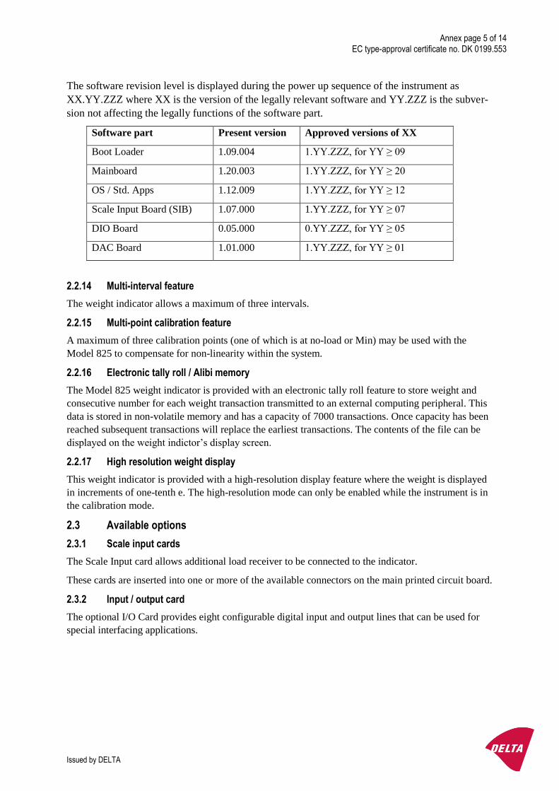
The software revision level is displayed during the power up sequence of the instrument as
XX.YY.ZZZ where XX is the version of the legally relevant software and YY.ZZZ is the subver-
sion not affecting the legally functions of the software part.
Software part Present version Approved versions of XX
Boot Loader 1.09.004 1.YY.ZZZ, for YY ≥ 09
Mainboard 1.20.003 1.YY.ZZZ, for YY ≥ 20
OS / Std. Apps 1.12.009 1.YY.ZZZ, for YY ≥ 12
Scale Input Board (SIB) 1.07.000 1.YY.ZZZ, for YY ≥ 07
DIO Board 0.05.000 0.YY.ZZZ, for YY ≥ 05
DAC Board 1.01.000 1.YY.ZZZ, for YY ≥ 01
2.2.14 Multi-interval feature
The weight indicator allows a maximum of three intervals.
2.2.15 Multi-point calibration feature
A maximum of three calibration points (one of which is at no-load or Min) may be used with the
Model 825 to compensate for non-linearity within the system.
2.2.16 Electronic tally roll / Alibi memory
The Model 825 weight indicator is provided with an electronic tally roll feature to store weight and
consecutive number for each weight transaction transmitted to an external computing peripheral. This
data is stored in non-volatile memory and has a capacity of 7000 transactions. Once capacity has been
reached subsequent transactions will replace the earliest transactions. The contents of the file can be
displayed on the weight indictor’s display screen.
2.2.17 High resolution weight display
This weight indicator is provided with a high-resolution display feature where the weight is displayed
in increments of one-tenth e. The high-resolution mode can only be enabled while the instrument is in
the calibration mode.
2.3 Available options
2.3.1 Scale input cards
The Scale Input card allows additional load receiver to be connected to the indicator.
These cards are inserted into one or more of the available connectors on the main printed circuit board.
2.3.2 Input / output card
The optional I/O Card provides eight configurable digital input and output lines that can be used for
special interfacing applications.

Annex page 6 of 14 EC type-approval certificate no. DK 0199.553
Issued by DELTA
3. Technical data
The weighing instrument is composed of separate modules, which are set out as follows:
3.1 Indicator
Type: Model 825
Accuracy class: III and IIII
Weighing range: Single-interval or multi-interval (max 3 intervals)
Maximum number of Verification Scale Intervals: 10000 (class III), 1000 (class IIII)
Internal resolution: >16,000,000 counts
Maximum tare effect: -Max1.
Fractional factor: p’I = 0.5
Minimum input-voltage per VSI: 0.5 µV
Minimum signal voltage for dead load: 1 mV
Excitation voltage: 10.85 VDC
Analogue range: 1 to 40 mV
Circuit for remote sense: Active
Minimum input-impedance: 25 ohms
Maximum input-impedance: 1100 ohms
Mains power supply: 90 - 260 VAC 50 or 60 Hertz
Peripheral interfaces: Set out in Section 4
3.1.1 Connecting cable between the indicator and a junction box for load cell(s), if any
Cable between Indicator and load cell(s): 6 wires (sense), shielded
Maximum cable length between indicator and junction box (J-box) for load cell(s), if any:
Option 1: 491 m/mm2
In case (n) for the weighing instrument is less than (n) mentioned above, the following applies:
Option 2:
Coefficient of temperature of the span error of the indicator: Es = 0.0043 [% / 25K]
Coefficient of resistance for the wires in the J-box cable: Sx = 0.0019 [% / ohm]
L/Amax = 295.86 / Sx * (emp / n – Es ) [ m / mm2 ] in which emp = p’I * mpe * 100 / e
From this, the maximum cable length for the weighing instrument may be calculated with regard to (n)
for the actual configuration of the instrument.
Reference: See Section 10.
The calculation program is obtainable by downloading at www.delta.dk/weighing.
3.2 Load receptors, load cells and load receptor supports
Removable platforms shall be equipped with level indicators.
3.2.1 General acceptance of modules
Any load cell(s) may be used for instruments under this certificate of type approval provided the fol-
lowing conditions are met:
1) There is a test certificate (EN 45501) or an OIML Certificate of Conformity (R60) issued for
the load cell by a Notified Body responsible for type examination under the Directive
2009/23/EC.

Annex page 7 of 14 EC type-approval certificate no. DK 0199.553
Issued by DELTA
2) The certificate contains the load cell types and the necessary load cell data required for the
manufacturer’s declaration of compatibility of modules (WELMEC 2, Issue 6, 2014, No.
11), and any particular installation requirements. A load cell marked NH is allowed only if
humidity testing to EN 45501 has been conducted on this load cell.
3) The compatibility of load cells and indicator is established by the manufacturer by means of
the compatibility of modules form, contained in the above WELMEC 2 document, or the
like, at the time of EC verification or declaration of EC conformity of type.
4) The load transmission must conform to one of the examples shown in the WELMEC 2.4
Guide for load cells.
3.2.2 Load cells
The load cells, which are listed below are certified as modules in the weighing instrument.
Manufacturer Load cell type
Cardinal SCA
Cardinal CB6
Cardinal TSP
Cardinal SB
Cardinal TB
Cardinal LFB
Cardinal DB
3.2.3 Weigh bridge platforms
Construction in brief: All-steel or steel-reinforced concrete construction, surface or pit mounted
Reduction ratio: 1
Junction box: Mounted in or on the platform
Load cells: Cardinal SCA, DB or other authorised alternative according to Section 3.2.1
Drawings: No. 3500-B089-0A and no. 3500-B018-0A (50,000 lb)
No. 3500-B094-0A (100,000 lb).
3.2.4 Platforms
Construction in brief: All-steel, aluminium, steel-reinforced concrete construction or hybrid con-
struction of these materials,
Bench, surface, pit or wall mounted
Reduction ratio: 1
Junction box: Mounted in or on the platform
Load cells Any R60 certified load cell according to Section 3.2.1 or 3.2.2
Drawings: Various
3.2.5 Bin, Tank, Hopper and non-standard systems
Construction in brief: Load cell assemblies each consisting of a load cell stand assembly to support
one of the mounting feet bin, tank or hopper
Reduction ratio: 1
Junction box: Mounted on dead structure
Load cell: Any R60 certified load cell according to Section 3.2.1 or 3.2.2
Drawings: Various

Annex page 8 of 14 EC type-approval certificate no. DK 0199.553
Issued by DELTA
3.3 Composition of modules
In case of composition of modules, EN 45501 paragraph 3.5 and 4.12 shall be satisfied.
3.4 Documents
The documents filed at DELTA (reference No. T203051) are valid for the weighing instruments de-
scribed here.
4. Interfaces and peripheral equipment
4.1 Interfaces
The interfaces are characterised “Protective interfaces” according to paragraph 8.4 in the Directive.
4.1.1 Load cell interface
A 7-terminal connector for the load receiver input is positioned on the scale input circuit board and is
accessed through a gland connector on the bottom panel of the instrument enclosure.
4.1.2 Printer interface
A 3-terminal connector for the printer is positioned on the indicator’s circuit board and is accessed
through a gland connector on the rear panel of the instrument enclosure.
4.1.3 Serial I/O interface
A 4-terminal connector providing a bi-directional RS232 compatible interface is positioned on the in-
dicator’s main circuit board and is accessed through a gland connector on the bottom panel of the in-
strument enclosure.
4.1.4 Ethernet interface
An Ethernet connector is located behind an access panel on the indicator enclosure and is accessed by
removal of the cover plate. This interface may be used when connecting to other peripheral devices.
4.1.5 USB interface
A USB interface is located behind an access panel on the indicator enclosure and is accessed by re-
moval of the cover plate. This interface may be used to download files or to interface with other pe-
ripheral devices. The maximum cable length for this interface shall be 2.9 m.
4.1.6 Logic Level Inputs and Outputs
A 10-terminal connector is used for the Model 825. This connector is located on the optional I/O card.
Access to the connector is made through a gland connector located on the bottom panel of the instru-
ment enclosure.
4.2 Peripheral equipment
Connection between the weight indicator and peripheral equipment is allowed by screened cable.
The instrument may be connected to any simple peripheral device with a CE mark of conformity.
4.2.1 Cardinal P220 Thermal Label Printer
The Cardinal P220 Thermal Label Printer is a RS232 serial driven label printer. It has a self-test facili-
ty which provides information of the software version and setup of the printer.
4.2.2 Cardinal P400 Dot Matrix Ticket Printer
The Cardinal P400 Dot Matrix Ticket Printer is a RS232 serial driven ticket printer. It has a self-test
facility which provides information of the software version and setup of the printer.

Annex page 9 of 14 EC type-approval certificate no. DK 0199.553
Issued by DELTA
4.2.3 Cardinal P500 Printer
The Cardinal P500 printer is a RS232 serial driven tally roll printer. It is equipped with automatic pa-
per out detection, which signals an error to a lamp on the front panel of the printer and also to the indi-
cator if the printer runs out of paper. The printer has an on / off power switch, a key for paper feed and
a key for switching between on-line and off-line. The printer is powered by a mains adapter for 230
VAC / 12 VDC or 110 VAC / 12 VDC.
5. Approval conditions
5.1 Measurement functions other than non-automatic functions
Measurement functions that will enable the use of the instrument as an automatic weighing instrument
are not covered by this type approval.
5.2 Application programs
Application software can only be downloaded when the indicator is in an unsealed condition. Loading
of an application program will increment the audit trail event counter regardless of settings. Applica-
tion software is not covered by this approval.
5.3 Compatibility of modules
In case of composition of modules, EN 45501:2015 annex F shall be satisfied.
6. Special conditions for verification
6.1 Composition of modules
The environmental conditions should be taken into consideration by the composition of modules for a
complete weighing instrument, for example instruments with load receptors placed outdoors and hav-
ing no special protection against the weather.
The composition of modules shall agree with Section 5.3.
An example of a declaration of conformity document is shown in Section 10.
6.2 Application software
Use the following procedure to check for the presence of application software:
Turn the indicator off, wait a few seconds then turn the 825 indicator on. The screen will perform a
self-test and display three options at the bottom of the screen. Within seven seconds, press the number
1 key to select the application program. Failure to press a key within this time will cause the automatic
execution of the application program.
Annex page 10 of 14 EC type-approval certificate no. DK 0199.553
Issued by DELTA
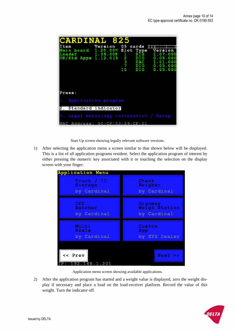
Start Up screen showing legally relevant software versions.
1) After selecting the application menu a screen similar to that shown below will be displayed.
This is a list of all application programs resident. Select the application program of interest by
either pressing the numeric key associated with it or touching the selection on the display
screen with your finger.
Application menu screen showing available applications.
2) After the application program has started and a weight value is displayed, zero the weight dis-
play if necessary and place a load on the load-receiver platform. Record the value of this
weight. Turn the indicator off.

Annex page 11 of 14 EC type-approval certificate no. DK 0199.553
Issued by DELTA
3) Turn the power back on to the indicator and, when the display returns to the initial display
shown in step 1, select the standard indicator selection by pressing the number 2 key or touch-
ing the selection on the screen.
4) After a short delay, the standard indicator screen will be displayed. Make sure the weight dis-
play is at zero then place the same load used in step 3 on the load-receiver platform. Compare
this value with the value recorded in step 3. The two values must be identical to validate the
application program.
5) To view the software version of the application program, start the application then select the
HELP and then ABOUT keys.
Serial Weight Data Output:
1) If the application program transmits weight from the COM 2 or another serial interface on the
indicator, a check should be made to verify its integrity. With the indicator executing the Ap-
plication program, inspect the weight data transmitted (if any) from the serial port(s).
2) Using a display terminal or similar device, connect it to COM 3 and view the weight data
transmitted from this protective interface. The weight data transmitted from COM 3 is the
gross weight from the Standard program and must be identical to the gross weight transmitted
from the Application program.
7. Securing and location of seals and verification marks
7.1 Securing and sealing
Seals shall bear the verification mark of a notified body or alternative mark of the manufacturer ac-
cording to ANNEX II, section 2.3 of the Directive 2009/23/EC.
7.1.1 Indicator
The 825 indicator provides an audit trail record for securing. At verification the value of the audit trail
counter is written on the inscription plate or on a brittle plastic sticker - sealed with a verification mark
- next to it.
If the value of the audit trail counter differs from the one written at verification time, the seal of the
indicator is broken.
7.1.2 Indicator - load cell connector - load receptor
Securing of the indicator, load receptor, and load cell combined is done by one of the following ways:
Sealing of the access to the interior of the enclosure of the indicator with brittle plastic sticker(s).
In special cases where the place of installation makes it impossible to use the above sealing:
Inserting the serial number of the load receptor as part of the principal inscriptions contained on the
indicator identification label.
7.1.3 Junction box for load cells
Access to the junction box, if any, is prevented by use of lead seals or by sealing it with brittle plastic
stickers.
7.1.4 Peripheral interfaces
All peripheral interfaces are “protective”; they neither allow manipulation with weighing data or Legal
Setup, nor change of the performance of the weighing instrument in any way that would alter the le-
gality of the weighing.
Annex page 12 of 14 EC type-approval certificate no. DK 0199.553
Issued by DELTA
7.2 Verification marks
7.2.1 Indicator
A green M-sticker and a sticker with verification marks may be placed on the front of the indicator or
on its inscription plate.
7.2.2 Printers used for legal transactions
Printers covered by this type of approval and other printers according to Section 4.2 shall not bear a
green M-sticker, although they are used for legal transactions, as a complete legal measuring instru-
ment shall only bear one green M-sticker.
7.2.3 Non-verified peripheral equipment
If such equipment is connected to the weighing instrument, it shall bear a red M-sticker.
8. Location of CE mark of conformity and inscriptions
8.1 Indicator
8.1.1 CE mark
A sticker with the CE mark of conformity and year of production is located on the identification plate
which is located on the side of the enclosure.
8.1.2 Inscriptions
Manufacturer’s trademark and name and the type designation is located on the front panel overlay.
Indelibly printed on a brittle plastic sticker located on the front panel overlay
Max, Min, e =, accuracy class
On the inscription plate - a single brittle plastic sticker - located on the side of the weight indicator:
Max, Min, e =
T = Max1, PT = Max1 (for multi-interval scale)
Certificate No., accuracy class
Model No., Serial No., electrical data and other inscriptions
8.2 Load receptors
On a data plate:
Manufacturer’s name, type, serial number, capacity
In special cases the load receptor bears the serial number of the indicator on its data plate.

Annex page 13 of 14 EC type-approval certificate no. DK 0199.553
Issued by DELTA
9. Pictures
Figure 1 Model 825 Front Panel
Figure 2 Model 825 Rear Panel

Annex page 14 of 14 EC type-approval certificate no. DK 0199.553
Issued by DELTA
10. Composition of modules – an example