ec5 / katelyn gunderson reviewed by: ec5/ lindsay … · prepared by: ec5 / katelyn gunderson...
TRANSCRIPT
CREW AND THERMAL SYSTEMS DIVISION
NASA - LYNDON B. JOHNSON SPACE CENTER
Test Plan for the
Bearing Dust Cycle Test
DOCUMENT NUMBER, REV
CTSD-ADV-1163, Baseline
DATE
September 25, 2014
PREPARED BY: EC5 / Katelyn Gunderson
REVIEWED BY: EC5/ Lindsay Aitchison
APPROVED BY: EC5/ Raul Blanco
No. Of Pages: 27 REVISIONS
REVISION PREPARER APPROVAL AUTHORIZED
LETTER/DATE BRANCH
https://ntrs.nasa.gov/search.jsp?R=20150000522 2018-07-15T04:21:05+00:00Z
CTSD-ADV-1163 Test Plan for the Bearing Dust Cycle Test Date: 09-25-2014 Page 2 of 27
Rev/Date Change Log
CTSD-ADV-1163 Test Plan for the Bearing Dust Cycle Test Date: 09-25-2014 Page 3 of 27
1.0 BACKGROUND
1.1 Test Objectives
The overall objective of these experiments is to test the dust-resistant seal on the high performance glove disconnect system (HPGD), to analyze the response of the bearing to lunar regolith simulant effects.
1.2 Methodology
The test setup seeks to simulate bearing rotation, in both CW and CCW directions, due to human wrist movement in a single axis. A total bearing rotation of 160 degrees (single axis rotation) has been selected for this study; the cyclic rotational motion of a motor shaft transfers this rotation to the bearing. Motor polarity is reversed by a latching relay triggered by magnetic limit switches. Torque measurements will be recorded during the entire test duration, through the use of an in-line torque sensor, to analyze any effects of dust intrusion in the bearing.
Lunar regolith simulate (JSC-1A) will be applied to the bearing surface either by direct constant contact or via pouring on bearing a set intervals (refer to Test Matrix in Section 5.1 for different test points). Torque reading before and after dust application will be taken. Test duration will be of 7-8 hours of continuous operation. It is intended to run as many 7-8 hour iterations as necessary until bearing is driven to “failure.” Refer to attached JSC-1A MSDS for further information on handling hazards.
Bearing Failure Criteria: Bearing failure criteria has been established as the point where the torque required to rotate the bearing in either direction is increased by 40% of the initial running torque.
Refer to the Experimental Procedure section of this document for test matrix, operational procedure, and “Simulant Application Log” sheet.
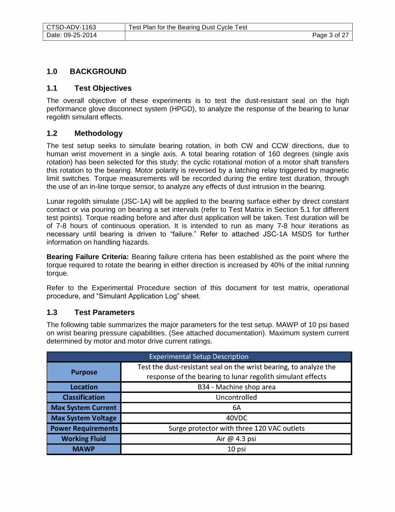
1.3 Test Parameters
The following table summarizes the major parameters for the test setup. MAWP of 10 psi based on wrist bearing pressure capabilities. (See attached documentation). Maximum system current determined by motor and motor drive current ratings.
CTSD-ADV-1163 Test Plan for the Bearing Dust Cycle Test Date: 09-25-2014 Page 4 of 27
Notes: DC power supplies are used to power up the system. No AC power flows through the system.
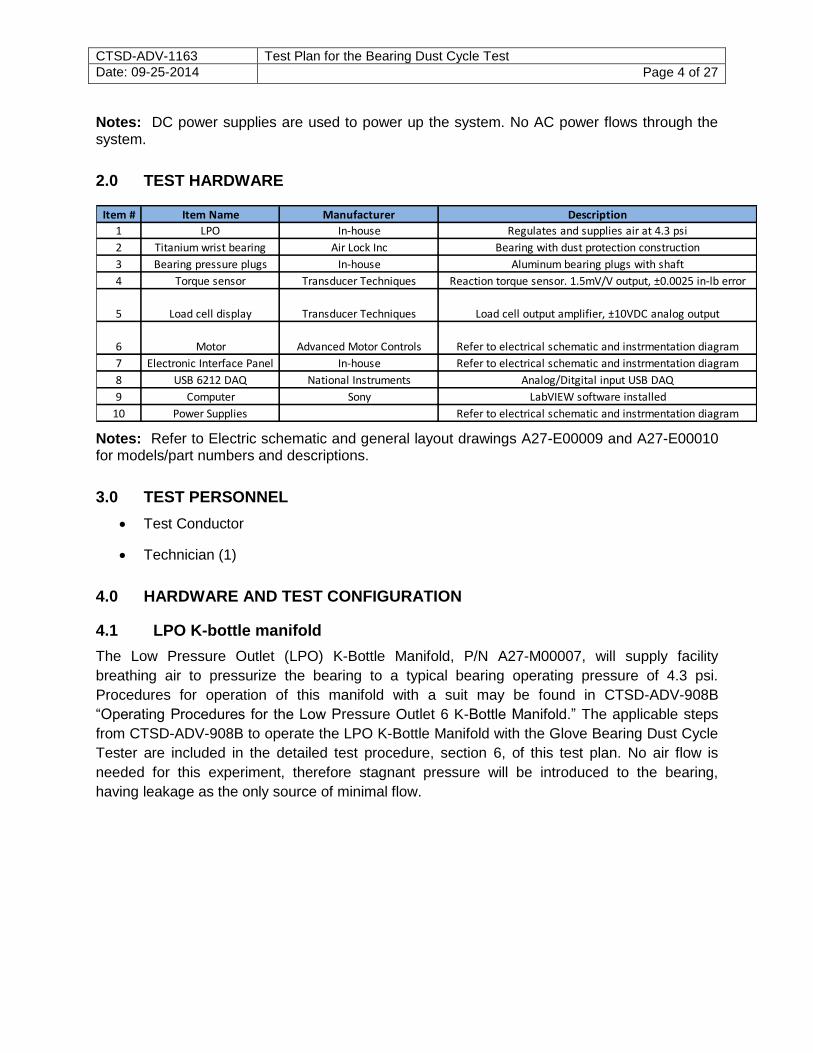
2.0 TEST HARDWARE
Item # Item Name Manufacturer Description
1 LPO In-house Regulates and supplies air at 4.3 psi
2 Titanium wrist bearing Air Lock Inc Bearing with dust protection construction
3 Bearing pressure plugs In-house Aluminum bearing plugs with shaft
4 Torque sensor Transducer Techniques Reaction torque sensor. 1.5mV/V output, ±0.0025 in-lb error
5 Load cell display Transducer Techniques Load cell output amplifier, ±10VDC analog output
6 Motor Advanced Motor Controls Refer to electrical schematic and instrmentation diagram
7 Electronic Interface Panel In-house Refer to electrical schematic and instrmentation diagram
8 USB 6212 DAQ National Instruments Analog/Ditgital input USB DAQ
9 Computer Sony LabVIEW software installed
10 Power Supplies Refer to electrical schematic and instrmentation diagram
Notes: Refer to Electric schematic and general layout drawings A27-E00009 and A27-E00010 for models/part numbers and descriptions.
3.0 TEST PERSONNEL
Test Conductor
Technician (1)
4.0 HARDWARE AND TEST CONFIGURATION
4.1 LPO K-bottle manifold
The Low Pressure Outlet (LPO) K-Bottle Manifold, P/N A27-M00007, will supply facility
breathing air to pressurize the bearing to a typical bearing operating pressure of 4.3 psi.
Procedures for operation of this manifold with a suit may be found in CTSD-ADV-908B
“Operating Procedures for the Low Pressure Outlet 6 K-Bottle Manifold.” The applicable steps
from CTSD-ADV-908B to operate the LPO K-Bottle Manifold with the Glove Bearing Dust Cycle
Tester are included in the detailed test procedure, section 6, of this test plan. No air flow is
needed for this experiment, therefore stagnant pressure will be introduced to the bearing,
having leakage as the only source of minimal flow.
CTSD-ADV-1163 Test Plan for the Bearing Dust Cycle Test Date: 09-25-2014 Page 5 of 27
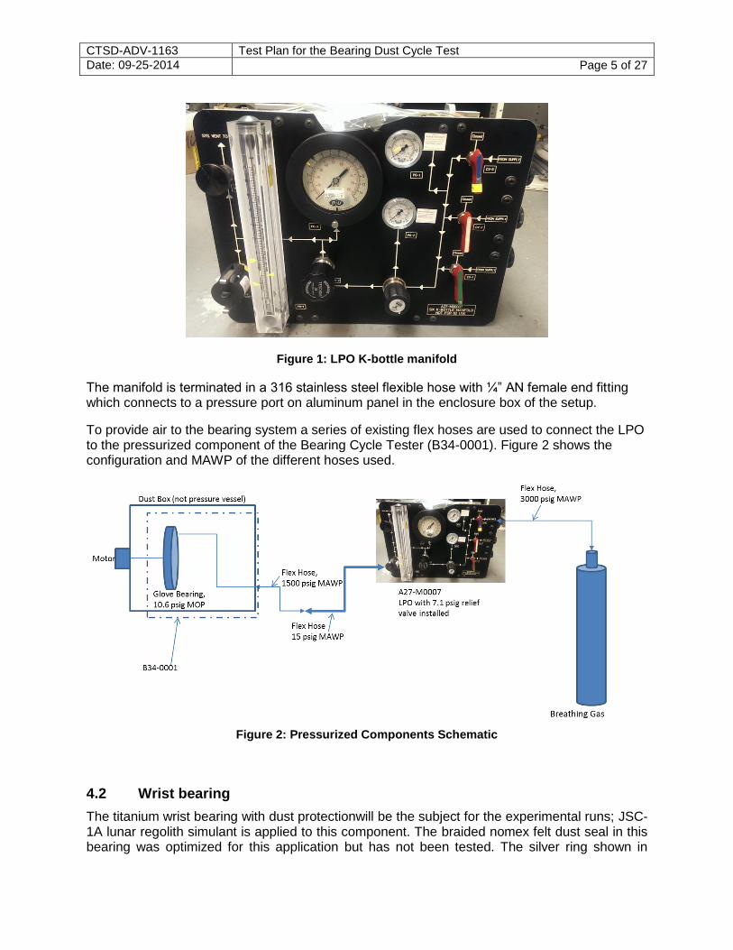
Figure 1: LPO K-bottle manifold
The manifold is terminated in a 316 stainless steel flexible hose with ¼” AN female end fitting which connects to a pressure port on aluminum panel in the enclosure box of the setup.
To provide air to the bearing system a series of existing flex hoses are used to connect the LPO to the pressurized component of the Bearing Cycle Tester (B34-0001). Figure 2 shows the configuration and MAWP of the different hoses used.
Figure 2: Pressurized Components Schematic
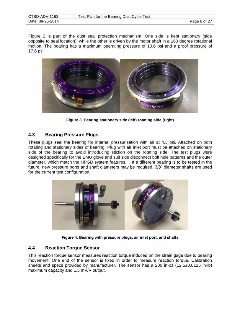
4.2 Wrist bearing
The titanium wrist bearing with dust protectionwill be the subject for the experimental runs; JSC-1A lunar regolith simulant is applied to this component. The braided nomex felt dust seal in this bearing was optimized for this application but has not been tested. The silver ring shown in
CTSD-ADV-1163 Test Plan for the Bearing Dust Cycle Test Date: 09-25-2014 Page 6 of 27
Figure 2 is part of the dust seal protection mechanism. One side is kept stationary (side opposite to seal location), while the other is driven by the motor shaft in a 160 degree rotational motion. The bearing has a maximum operating pressure of 10.6 psi and a proof pressure of 17.6 psi.
Figure 3. Bearing stationary side (left) rotating side (right)
4.3 Bearing Pressure Plugs
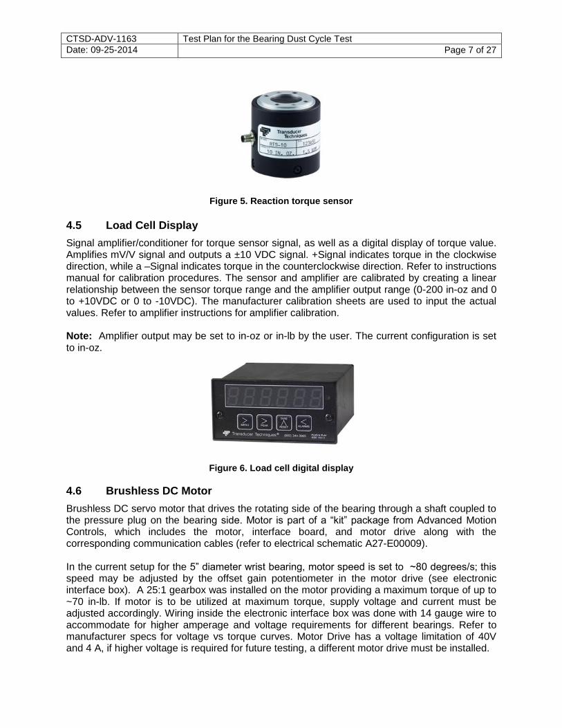
These plugs seal the bearing for internal pressurization with air at 4.3 psi. Attached on both rotating and stationary sides of bearing. Plug with air inlet port must be attached on stationary side of the bearing to avoid introducing stiction on the rotating side. The test plugs were designed specifically for the EMU glove and suit side disconnect bolt hole patterns and the outer diameter, which match the HPGD system features. . If a different bearing is to be tested in the future, new pressure ports and shaft diameters may be required. 3/8” diameter shafts are used for the current test configuration.
Figure 4. Bearing with pressure plugs, air inlet port, and shafts
4.4 Reaction Torque Sensor
This reaction torque sensor measures reaction torque induced on the strain gage due to bearing movement. One end of the sensor is fixed in order to measure reaction torque. Calibration sheets and specs provided by manufacturer. The sensor has a 200 in-oz (12.5±0.0125 in-lb) maximum capacity and 1.5 mV/V output.
CTSD-ADV-1163 Test Plan for the Bearing Dust Cycle Test Date: 09-25-2014 Page 7 of 27
Figure 5. Reaction torque sensor
4.5 Load Cell Display
Signal amplifier/conditioner for torque sensor signal, as well as a digital display of torque value. Amplifies mV/V signal and outputs a ±10 VDC signal. +Signal indicates torque in the clockwise direction, while a –Signal indicates torque in the counterclockwise direction. Refer to instructions manual for calibration procedures. The sensor and amplifier are calibrated by creating a linear relationship between the sensor torque range and the amplifier output range (0-200 in-oz and 0 to +10VDC or 0 to -10VDC). The manufacturer calibration sheets are used to input the actual values. Refer to amplifier instructions for amplifier calibration. Note: Amplifier output may be set to in-oz or in-lb by the user. The current configuration is set to in-oz.
Figure 6. Load cell digital display
4.6 Brushless DC Motor
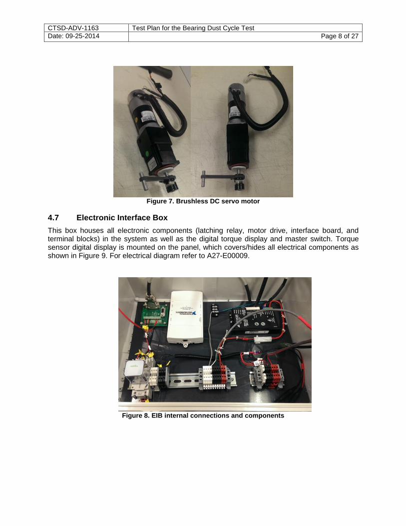
Brushless DC servo motor that drives the rotating side of the bearing through a shaft coupled to the pressure plug on the bearing side. Motor is part of a “kit” package from Advanced Motion Controls, which includes the motor, interface board, and motor drive along with the corresponding communication cables (refer to electrical schematic A27-E00009). In the current setup for the 5” diameter wrist bearing, motor speed is set to ~80 degrees/s; this speed may be adjusted by the offset gain potentiometer in the motor drive (see electronic interface box). A 25:1 gearbox was installed on the motor providing a maximum torque of up to ~70 in-lb. If motor is to be utilized at maximum torque, supply voltage and current must be adjusted accordingly. Wiring inside the electronic interface box was done with 14 gauge wire to accommodate for higher amperage and voltage requirements for different bearings. Refer to manufacturer specs for voltage vs torque curves. Motor Drive has a voltage limitation of 40V and 4 A, if higher voltage is required for future testing, a different motor drive must be installed.
CTSD-ADV-1163 Test Plan for the Bearing Dust Cycle Test Date: 09-25-2014 Page 8 of 27
Figure 7. Brushless DC servo motor
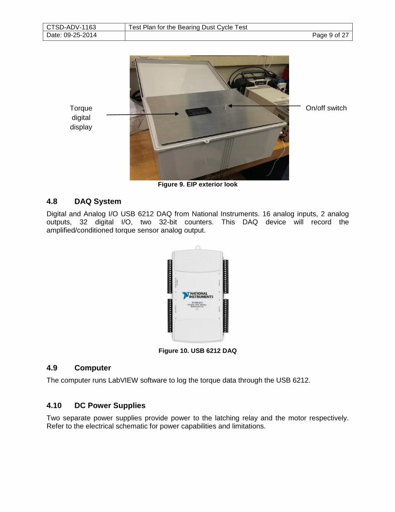
4.7 Electronic Interface Box
This box houses all electronic components (latching relay, motor drive, interface board, and terminal blocks) in the system as well as the digital torque display and master switch. Torque sensor digital display is mounted on the panel, which covers/hides all electrical components as shown in Figure 9. For electrical diagram refer to A27-E00009.
Figure 8. EIB internal connections and components
CTSD-ADV-1163 Test Plan for the Bearing Dust Cycle Test Date: 09-25-2014 Page 9 of 27
Figure 9. EIP exterior look
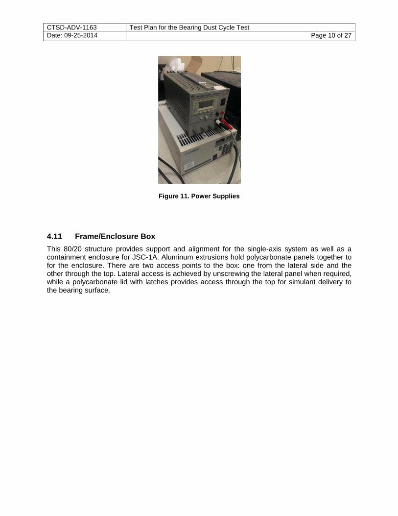
4.8 DAQ System
Digital and Analog I/O USB 6212 DAQ from National Instruments. 16 analog inputs, 2 analog outputs, 32 digital I/O, two 32-bit counters. This DAQ device will record the amplified/conditioned torque sensor analog output.
Figure 10. USB 6212 DAQ
4.9 Computer
The computer runs LabVIEW software to log the torque data through the USB 6212.
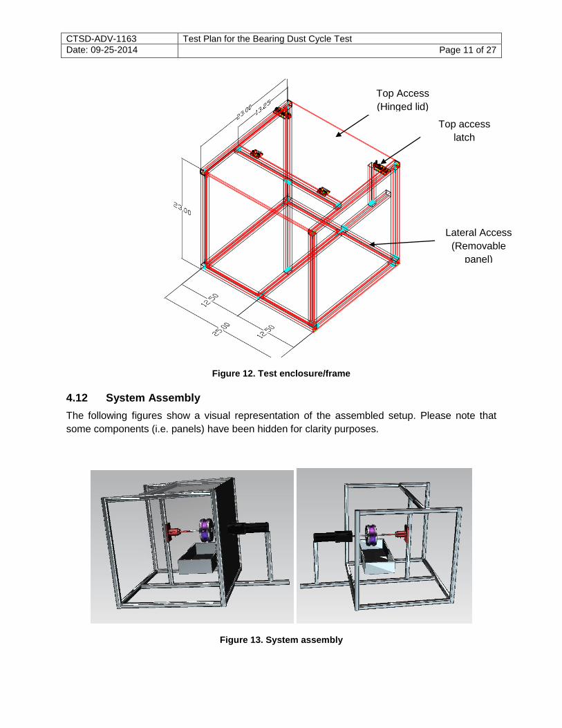
4.10 DC Power Supplies
Two separate power supplies provide power to the latching relay and the motor respectively. Refer to the electrical schematic for power capabilities and limitations.
Torque
digital
display
On/off switch
CTSD-ADV-1163 Test Plan for the Bearing Dust Cycle Test Date: 09-25-2014 Page 10 of 27
Figure 11. Power Supplies
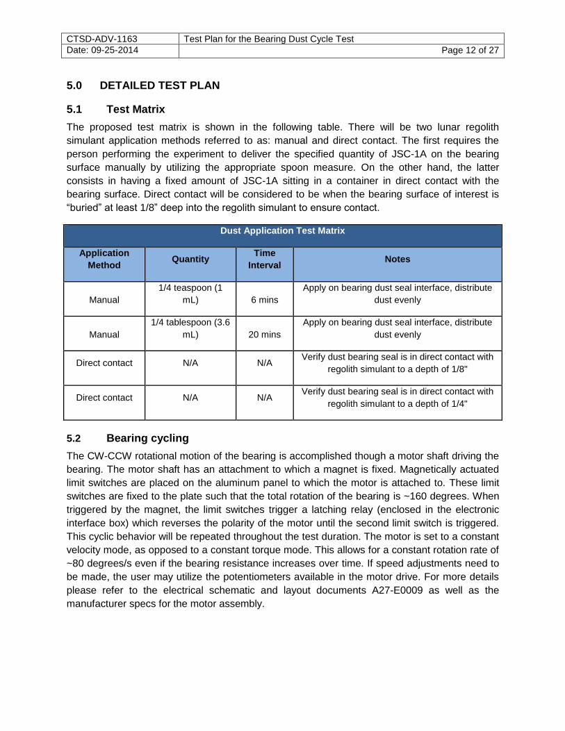
4.11 Frame/Enclosure Box
This 80/20 structure provides support and alignment for the single-axis system as well as a containment enclosure for JSC-1A. Aluminum extrusions hold polycarbonate panels together to for the enclosure. There are two access points to the box: one from the lateral side and the other through the top. Lateral access is achieved by unscrewing the lateral panel when required, while a polycarbonate lid with latches provides access through the top for simulant delivery to the bearing surface.
CTSD-ADV-1163 Test Plan for the Bearing Dust Cycle Test Date: 09-25-2014 Page 11 of 27
Figure 12. Test enclosure/frame
4.12 System Assembly
The following figures show a visual representation of the assembled setup. Please note that
some components (i.e. panels) have been hidden for clarity purposes.
Figure 13. System assembly
Top Access
(Hinged lid)
Top access
latch
Lateral Access
(Removable
panel)
CTSD-ADV-1163 Test Plan for the Bearing Dust Cycle Test Date: 09-25-2014 Page 12 of 27
5.0 DETAILED TEST PLAN
5.1 Test Matrix
The proposed test matrix is shown in the following table. There will be two lunar regolith
simulant application methods referred to as: manual and direct contact. The first requires the
person performing the experiment to deliver the specified quantity of JSC-1A on the bearing
surface manually by utilizing the appropriate spoon measure. On the other hand, the latter
consists in having a fixed amount of JSC-1A sitting in a container in direct contact with the
bearing surface. Direct contact will be considered to be when the bearing surface of interest is
“buried” at least 1/8” deep into the regolith simulant to ensure contact.
Dust Application Test Matrix
Application
Method Quantity
Time
Interval Notes
Manual
1/4 teaspoon (1
mL) 6 mins
Apply on bearing dust seal interface, distribute
dust evenly
Manual
1/4 tablespoon (3.6
mL) 20 mins
Apply on bearing dust seal interface, distribute
dust evenly
Direct contact N/A N/A Verify dust bearing seal is in direct contact with
regolith simulant to a depth of 1/8"
Direct contact N/A N/A Verify dust bearing seal is in direct contact with
regolith simulant to a depth of 1/4"
5.2 Bearing cycling
The CW-CCW rotational motion of the bearing is accomplished though a motor shaft driving the
bearing. The motor shaft has an attachment to which a magnet is fixed. Magnetically actuated
limit switches are placed on the aluminum panel to which the motor is attached to. These limit
switches are fixed to the plate such that the total rotation of the bearing is ~160 degrees. When
triggered by the magnet, the limit switches trigger a latching relay (enclosed in the electronic
interface box) which reverses the polarity of the motor until the second limit switch is triggered.
This cyclic behavior will be repeated throughout the test duration. The motor is set to a constant
velocity mode, as opposed to a constant torque mode. This allows for a constant rotation rate of
~80 degrees/s even if the bearing resistance increases over time. If speed adjustments need to
be made, the user may utilize the potentiometers available in the motor drive. For more details
please refer to the electrical schematic and layout documents A27-E0009 as well as the
manufacturer specs for the motor assembly.

CTSD-ADV-1163 Test Plan for the Bearing Dust Cycle Test Date: 09-25-2014 Page 13 of 27
5.3 Dust Application
During handling of the JSC-1A simulant test personnel must wear appropriate PPE as
prescribed by the MSDS (JSC #39744) which includes latex gloves, face mask (NIOSH
nuisance dust masks), and safety goggles. Please refer to CTSD-ADV-1164 “Hazards Analysis
for the Glove Bearing Dust Cycle Test.” Manual application will be done at the time intervals
specified in Section 5.1
Personnel conducting the test must fill the “JSC-1A Simulant Application Log Sheet” where they
will input torque reading before dust application, time of application, and personnel initials. This
form serves as a data logging mechanism, as well as a safety control by ensuring the system is
operating correctly throughout the test duration.
During direct contact runs, test personnel may initial the sheet every 30 minutes and record
torque measurements at those intervals.
5.4 Test Termination Criteria
Overall Test Termination Criteria:
At any time for any reason by test personnel
Hardware failure
Torque Increase Termination Criteria:
Torque shows a 40% increase from the initial torque value of the experimental runs.
This test may be terminated by the test conductor and/or technicians at any time for any reason,
due to any safety or hardware concerns.
CTSD-ADV-1163 Test Plan for the Bearing Dust Cycle Test Date: 09-25-2014 Page 14 of 27
6.0 DETAILED TEST PROCEDURES
The following sections contain the procedures to set up for and complete the Glove Bearing Dust Cycle Test. In the event a test last multiple days the system Initial System Inspection (Section 6.2) and LPO Set up and Leak Test Procedure (Section 6.3) will be repeated prior to the commencement of testing (Section 6.4 or 6.5) each day to ensure the system is in good working order. At the conclusion of testing each day the Shutdown Procedure (Section 6.6) will be completed to make sure the system is stored safely.
6.1 Test-Specific Pre-Test Safety Review
1. Anyone can stop this test at any time for any reason
2. Record and initial the log sheet.
3. Use safety goggles at all times during experimental procedures
4. Use latex gloves when handling lunar regolith simulant JSC-1A (refer to attached MSDS
for further information)
5. Use dust mask when handling lunar regolith simulant JSC-1A (refer to attached MSDS
for further information)
6. Verify all connectors are properly engaged
7. Monitor setup during long duration experiments to ensure proper functionality of test rig
every 15 minutes. Never leave setup unattended.
8. Ensure adequate ventilation is available during the time of the experimental procedure
CTSD-ADV-1163 Test Plan for the Bearing Dust Cycle Test Date: 09-25-2014 Page 15 of 27
6.2 Initial System Inspection
This section completes pre-test inspections and check outs of the Glove Bearing Dust Cycle
Test stand to ensure the system in in operating order prior to pressurization and dust
application.
Note: This step only needs to be completed on the first day of each test round and can be N/A’d for subsequent days when the test configuration has not been altered.
Verify that prior to the start of the first day of testing the glove bearing has been cleaned and a fresh (no dust exposure) Nomex dust resistant seal was installed. Record on test sheet when the maintenance was completed and weight of seal prior to the start of testing.
____ 6.2.1. Complete visual inspection of all components in the setup (motor, connectors
and wires from interface box, bearing and shafts, frame/enclosure).
Clean/Repair components as required.
____ 6.2.2. Verify stand/enclosure struts are secure and tightened
____ 6.2.3. Verify motor, drive shafts, couplings, bearing, and torque sensor are in line
and their attachment bolts are tightened
____ 6.2.4. Inspection of polycarbonate panels (check for cracks or leak points)
CTSD-ADV-1163 Test Plan for the Bearing Dust Cycle Test Date: 09-25-2014 Page 16 of 27
6.3 LPO Set up and Leak Test Procedure
Note: Pressurization must be conducted by personnel familiar and certified to use the LPO
K-bottle manifold. If personnel with such qualifications are not present, stop test until one is
available.
____ 6.3.1. Collect the following Components:
1 ea LPO Manifold
1 ea Flex hose rated to 3000 psig MAWP or greater
1 ea Flex hose rated to 150 psig MAWP or greater
1 ea Darling flex hose rated to 15 psig MAWP or greater
1 ea Apollo Connector Part Number 899G
1 ea Green Apple with ¼” AN Male fitting attached
6.3.2. Verify the following on the Low Pressure Outlet 6K-Bottle Manifold
____ CLASS I DUE DATE __________________ ____ PG-3 CAL. DUE DATE __________________ ____ FM-1 CAL. DUE DATE __________________ ____ RV-1 CAL. DUE DATE __________________ ____ RV-2 CAL. DUE DATE __________________ ____ SYSTEM SAMPLING DUE DATE __________________
____ 6.3.3. Verify/place all control valves in Normal Pre-Test Starting Positions per below table. CV-1 CLOSED CV-2 CLOSED CV-3 CLOSED PRV-1 FULL COUNTER CLOCKWISE (CCW) PRV-2 FULL COUNTER CLOCKWISE (CCW) PG-1 “0” PSIG PG-2 “0” PSIG PG-3 “0” PSIG HV-1 FULL CLOSED VV-1 FULL CLOSED VV-2 FULL CLOSED VV-3 FULL CLOSED LPV-1 CLOSED
CTSD-ADV-1163 Test Plan for the Bearing Dust Cycle Test Date: 09-25-2014 Page 17 of 27
____ 6.3.4. Connect/Verify approved air supply (k-bottle) to inlet port of CV-3 on LPO Manifold with a flex hose rated to 3000 psig MAWP and record the following:
____ FLEX HOSE S/N
______________ MAWP _____________PSIG EXP ______
____ 6.3.5. Connect/Verify Darling Flex Hose to LPO Manifold outlet and record the following:
____ FLEX HOSE S/N
______________ MAWP _____________PSIG EXP ______
____ 6.3.6. Connect/Verify Apollo connector 899G to the outlet of the Darling Flex Hose.
____ 6.3.7. Connect/Verify the Green Apple connector to the outlet of the Apollo 899G.
____ 6.3.8. Connect/Verify a flex hose rated to 150 psig MAWP or greater to the outlet of the Green Apple connector and record the following:
____ FLEX HOSE S/N
______________ MAWP _____________PSIG EXP ______
____ 6.3.9. Verify/Connect the outlet of the 150 psig MAWP flex hose to the inlet of the Bearing Cycle Tester (B34-0001).
____ 6.3.10. Slowly open K-Bottle Valve.
____ 6.3.11. Slowly open CV-3 on LPO Manifold and record pressure from PG-1:_______
____ 6.3.12. Slowly increase PRV-1 (CW) to obtain a pressure of 30 +/- 10 psig.
____ 6.3.13. Slowly increase PRV-2 until PG-3 reads 4.3 ± 0.2 PSIG.
____ 6.3.14. Check for leaks (audible and pressure maintained at 4.3 psig) of system.
Troubleshoot as required.
CTSD-ADV-1163 Test Plan for the Bearing Dust Cycle Test Date: 09-25-2014 Page 18 of 27
6.4 Experimental Procedure – Manual Dust Application
Note: The following section shall be used for manual dust application testing. In event direct contact application is used (section 6.5) N/A this portion of the test procedure.
____ 6.4.1. Verify master switch (SW-3) is in the OFF position
____ 6.4.2. Connect/Verify AC power chord is connected
____ 6.4.3. Connect/Verify DC power supplies are connected to interface box (follow wire
tags)
____
6.4.4. Set DC power supplies (PS-1 and PS-2) to 20 VDC 0.3A
For PS-1:
1. Turn course and fine voltage adjustments CCW until hard stop
2. Turn power supply on
3. Adjust voltage to 20 VDC
For PS-2:
1. Turn power supply on
2. Set program and operation modes to volts if not already in this
configuration
3. Press “Standby” button
4. Enter 20 VDC and press “Enter”
5. Press “Standby” button
____ 6.4.5. Turn master switch (SW-3) to ON position. Verify motor starts rotating in the
CW-CCW motion.
____ 6.4.6. Verify power supplies (PS-1 and PS-2) are set to output 20 VDC
____ 6.4.7. Verify proper functionality of system components (motor, limit switches,
electrical interface box, master switch, etc.)
____ 6.4.8. Verify torque sensor and amplifier are powered and displaying the same
value in both LabVIEW and the digital display
CTSD-ADV-1163 Test Plan for the Bearing Dust Cycle Test Date: 09-25-2014 Page 19 of 27
____ 6.4.9. Turn master switch (SW-3) to the OFF position.
____ 6.4.10. Record initial weight of dust container on Data Sheet (Manual Application).
____ 6.4.11. Set platform with dust containment container to desired height directly underneath bearing assembly
____ 6.4.12. Close and latch top lid
____ 6.4.13. Screw lateral access panel in place
____ 6.4.14. Turn master switch (SW-3) to ON position. Verify motor starts rotating in the CW-CCW motion.
____ 6.4.15. Open LabVIEW software and open data logging program
____ 6.4.16. Click “Run” button in LabVIEW interface.
____ 6.4.17.
Enable “Data Recording” virtual switch in LabVIEW interface to begin data
recording.
____ 6.4.18.
Allow system to run for at least 60 seconds to gather baseline torque value.
Record baseline torque value on Data Sheet (Manual Application).
____ 6.4.19. Verify tester is wearing PPE (Safety Goggles, Gloves, and Dust Mask).
____ 6.4.20.
Apply lunar regolith simulant as required per test matrix until torque value has
increased 40% from the baseline measurement taken on the first day of
testing. Record torque values and lunar regolith application on the Data Sheet
(Manual Application).
____ 6.4.21.
Check system every 15 minutes for proper functionality of the following.
Record completion on Data Sheet (System Check List)
a. Cyclic motion controlled by limit switches
b. Torque measured being displayed and recorded
c. Motor temperature poses no risk to personnel or equipment
working in surrounding areas
d. Pressure maintained at 4.3 psig +/- 0.2 psig. Adjust PRV-2 as
required.
CTSD-ADV-1163 Test Plan for the Bearing Dust Cycle Test Date: 09-25-2014 Page 20 of 27
6.5 Experimental Procedure – Direct Contact Dust Application
Note: The following section shall be used for direct contact dust application testing. In event manual dust application is used (section 6.4) N/A this portion of the test procedure.
____ 6.5.1. Verify master switch (SW-3) is in the OFF position
____ 6.5.2. Connect/Verify AC power chord is connected
____ 6.5.3. Connect/Verify DC power supplies are connected to interface box (follow wire tags)
____
6.5.4. Set DC power supplies (PS-1 and PS-2) to 20 VDC 0.3A For PS-1:
1. Turn course and fine voltage adjustments CCW until hard stop
2. Turn power supply on
3. Adjust voltage to 20 VDC
For PS-2:
1. Turn power supply on
2. Set program and operation modes to volts if not already in this
configuration
3. Press “Standby” button
4. Enter 20 VDC and press “Enter”
5. Press “Standby” button
____ 6.5.5. Turn master switch (SW-3) to ON position. Verify motor starts rotating in the
CW-CCW motion.
____ 6.5.6. Verify power supplies (PS-1 and PS-2) are set to output 20 VDC
____ 6.5.7. Verify proper functionality of system components (motor, limit switches, electrical interface box, master switch, etc.)
____ 6.5.8. Verify torque sensor and amplifier are powered and displaying the same value in both LabVIEW and the digital display
____ 6.5.9. Click “Run” button in LabVIEW interface.
CTSD-ADV-1163 Test Plan for the Bearing Dust Cycle Test Date: 09-25-2014 Page 21 of 27
____ 6.5.10. Enable “Data Recording” virtual switch in LabVIEW interface to begin data recording.
____ 6.5.11. Allow system to run for at least 60 seconds to gather baseline torque value. Record baseline torque value on Data Sheet (Direct Contact Application).
____ 6.5.12. Turn master switch (SW-3) to OFF position. Verify motor stops rotating.
____ 6.5.13. Verify tester is wearing PPE (Safety Goggles, Gloves, and Dust Mask).
Verify tester is not wearing ties or credential holders.
____ 6.5.14. Set up platform with dust container such that bearing is submerged to desired depth per test matrix.
____ 6.5.15. Close and latch top lid
____ 6.5.16. Screw lateral access panel in place
____ 6.5.17.
Turn master switch (SW-3) to ON position. Verify motor starts rotating in the
CW-CCW motion.
____ 6.5.18.
Allow system to run until torque value has increased 40% from the baseline
measurement taken on the first day of testing. Record torque values every 30
minutes on Data Sheet (Direct Contact Application)
____ 6.5.19.
Check system every 15 minutes for proper functionality of the following.
Record completion on Data Sheet (System Check List)
a. Cyclic motion controlled by limit switches
b. Torque measured being displayed and recorded
c. Motor temperature poses no risk to personnel or equipment
working in surrounding areas
d. Pressure maintained at 4.3 psig +/- 0.2 psig. Adjust PRV-2 as
required.
CTSD-ADV-1163 Test Plan for the Bearing Dust Cycle Test Date: 09-25-2014 Page 22 of 27
6.6 System Shutdown
____ 6.6.1. Stop data logging in LabVIEW.
____ 6.6.2. Turn master switch (SW-3) to the OFF position. Verify Motor has stopped
rotating.
____ 6.6.3. Turn DC power supplies (PS-1 and PS-2) OFF
____ 6.6.4. Close K Bottle valve.
____ 6.6.5. Depressurize system by slowly opening HV-1 until all pressure gauges read 0.
____ 6.6.6. Close HV-1.
____ 6.6.7. Slowly decrease (CCW) PRV-1 and PRV-2 till closed.
____ 6.6.8. Slowly close CV-3.
____ 6.6.9. Disconnect 150 psig MAWP flex hose from inlet of Bearing Cycle Tester.
____ 6.6.10. Complete visual inspection of experiment setup.
____ 6.6.11. Remove dust container and record its weight.
CTSD-ADV-1163 Test Plan for the Bearing Dust Cycle Test Date: 09-25-2014 Page 23 of 27
6.7 System Disassembly
Note: The following step shall only be completed when 40% torque increase has been reached or the test run has been terminated. If the test is continuing on subsequent days this step can be N/A’d.
____ 6.7.2 Don PPE (Safety Goggles, Gloves, and Dust Mask)
____ 6.7.3 Open test enclosure box
____ 6.7.4 Vacuum any loose lunar regolith simulant from the test stand using the 6 gallon blue Shop Vac with a HEPA filter installed.
____ 6.7.5 Remove wrist bearing from test stand. Gently remove Nomex dust resistant seal and weight. Record weight on data collection sheet.
____ 6.7.6 Clean bearing with Isopropyl alcohol.
____ 6.7.7 Properly dispose of lunar regolith simulant by placing the Shop Vac filter bag inside of a trash bag, tying the top of the bag closed, and placing inside a trash bin.
CTSD-ADV-1163 Test Plan for the Bearing Dust Cycle Test Date: 09-25-2014 Page 24 of 27
6.8 Emergency Procedure
Close K-Bottle
Slowly open HV-1 till all gauges read 0 psig.
Close HV-1.
Shut down all electrical components in system by pressing “Kill switch” on surge
protector
Follow Standard Lab procedures for emergency evacuation and/notification as required.
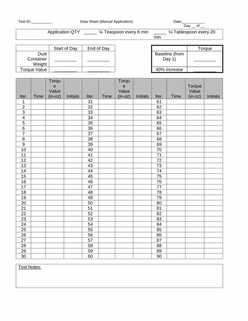
Test ID:__________ Data Sheet (Manual Application) Date:___________ Day __ of __
Application QTY _____ ¼ Teaspoon every 6 min _____ ¼ Tablespoon every 20 min
Start of Day End of Day Torque
Dust Container
Weight
_________
_________
Baseline (from Day 1)
_________
Torque Value _________ _________ 40% Increase _________
Iter. Time
Torque
Value (in-oz) Initials Iter. Time
Torque
Value (in-oz) Initials Iter. Time
Torque Value (in-oz) Initials
1 31 61
2 32 62
3 33 63
4 34 64
5 35 65
6 36 66
7 37 67
8 38 68
9 39 69
10 40 70
11 41 71
12 42 72
13 43 73
14 44 74
15 45 75
16 46 76
17 47 77
18 48 78
19 49 79
20 50 80
21 51 81
22 52 82
23 53 83
24 54 84
25 55 85
26 56 86
27 57 87
28 58 88
29 59 89
30 60 90
Test Notes:
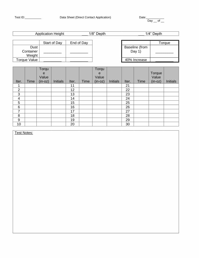
Test ID:__________ Data Sheet (Direct Contact Application) Date:___________ Day __ of __
Application Height ___ 1/8” Depth ___ 1/4” Depth
Start of Day End of Day Torque
Dust Container
Weight
_________
_________
Baseline (from Day 1)
_________
Torque Value _________ _________ 40% Increase _________
Iter. Time
Torque
Value (in-oz) Initials Iter. Time
Torque
Value (in-oz) Initials Iter. Time
Torque Value (in-oz) Initials
1 11 21
2 12 22
3 13 23
4 14 24
5 15 25
6 16 26
7 17 27
8 18 28
9 19 29
10 20 30
Test Notes:
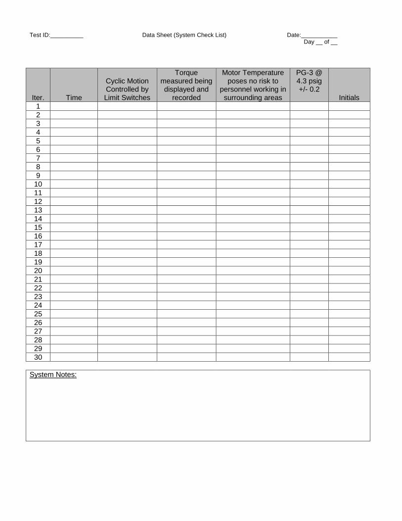
Test ID:__________ Data Sheet (System Check List) Date:___________ Day __ of __
Iter. Time
Cyclic Motion Controlled by Limit Switches
Torque measured being displayed and
recorded
Motor Temperature poses no risk to
personnel working in surrounding areas
PG-3 @ 4.3 psig +/- 0.2
Initials
1
2
3
4
5
6
7
8
9
10
11
12
13
14
15
16
17
18
19
20
21
22
23
24
25
26
27
28
29
30
System Notes: