ecc report 162 practical mechanism to improve the
TRANSCRIPT

ECC REPORT 162
Electronic Communications Committee (ECC) within the European Conference of Postal and Telecommunications Administrations (CEPT)
ECC REPORT 162
PRACTICAL MECHANISM TO IMPROVE THE COMPATIBILITY BETWEEN GSM-R AND
PUBLIC MOBILE NETWORKS AND GUIDANCE ON PRACTICAL COORDINATION
Montegrotto Terme, May 2011
ECC REPORT 162 Page 2
0 EXECUTIVE SUMMARY
In the CEPT countries, the frequency bands 880-915 MHz (Uplink) and 925-960 MHz (Downlink) are allocated to mobile services and are currently used for GSM and UMTS networks but also planned for the usage by LTE and WiMAX and in the future other public mobile networks. All these networks are denominated as public mobile networks in this Report. The frequency bands 876-880 MHz (Uplink) and 921-925 MHz (Downlink) (GSM-R band) are harmonised within CEPT for the operational communication of railway companies (GSM-R) in accordance with ECC/DEC/(02)05. In addition, in accordance with ECC/DEC/(04)06, the frequency bands 873-876 MHz (Uplink) and 918-921 MHz (Downlink) (E-GSM-R band) may also be used as extension bands for GSM-R on a national basis. Recently some GSM-R operators have noticed operational limitations caused by interferences to their networks from public mobile networks emissions. Coordination carried out between public mobile networks and GSM-R operators in some countries shows that there exist some remedies to alleviate these interferences. In the future, the number of interference cases may increase, due to the expected growth of GSM-R network deployment and the potential growth of public mobile networks. Moreover, public mobile networks may suffer from GSM-R mobile station emissions when deployed in adjacent frequencies and in geographical close vicinity. This Report focuses on the coexistence between public mobile networks operating in the 900 MHz band and GSM-R networks operating both in the GSM-R band (876-880 MHz / 921-925 MHz) and the E-GSM-R band (873-876 MHz / 918-921 MHz). Several scenarios have been identified as relevant whereas most of them have already been studied in CEPT (ECC Reports 096 and 146 and CEPT Report 41). Consequently the existing results have been taken into account with complements added for some of them. Several scenarios between public mobile networks and GSM-R have been studied in detail in this Report in particular those involving E-GSM-R. This Report provides guidance to improve the coexistence between GSM-R and public mobile networks and describes potential mitigation techniques which may be considered by national administrations and/or operators on both sides to address interference cases between GSM-R and public mobile networks on a local/regional/national basis. It should be noted that the list of measures is not exhaustive and that additional spectrum engineering techniques may be considered on a case-by-case basis. Applying a single one of the measures may not be sufficient in all cases but rather a combination of methods. In addition preventive methods to avoid interference situations between GSM-R and public mobile networks can be applied on a national/regional basis. Interoperability and continuity of GSM-R service shall be ensured from one country to another one, as well as public operators' licence obligations have to be fulfilled. In general the use of mitigation techniques should be limited to the cases necessary in order to avoid undue constraints on both networks and facilitate an efficient use of spectrum.
ECC REPORT 162 Page 3
Table of contents
0 EXECUTIVE SUMMARY ............................................................................................................................................ 2
LIST OF ABBREVIATIONS ................................................................................................................................................ 4
1 INTRODUCTION .......................................................................................................................................................... 6
2 FREQUENCY USAGE .................................................................................................................................................. 6
3 SYSTEM DESCRIPTION ............................................................................................................................................. 7
3.1 PUBLIC MOBILE NETWORKS IN THE 900 MHZ BAND .................................................................................................. 7 3.2 GSM-R ...................................................................................................................................................................... 7
3.2.1 GSM-R application description ........................................................................................................................ 7 3.2.2 GSM-R specific requirements ........................................................................................................................... 8
4 OBSERVATIONS AND CAUSES OF INTERFERENCE ......................................................................................... 8
5 COEXISTENCE SCENARIOS ................................................................................................................................... 10
5.1 PRINCIPLE INTERFERENCE SCENARIOS BETWEEN GSM-R AND PUBLIC MOBILE NETWORKS..................................... 10 5.2 COMPATIBILITY CASES ............................................................................................................................................ 11
5.2.1 Studies already completed .............................................................................................................................. 11 5.2.2 E-GSM-R into the bands 873-876 MHz and 918-921 MHz on a national basis ............................................. 14 5.2.3 Studies covered in this Report ......................................................................................................................... 14
5.3 IMPACT FROM GSM AND UMTS UL (915 MHZ) ON E-GSM-R DL (918 MHZ) ...................................................... 15 5.4 IMPACT FROM E-GSM-R DL (918 MHZ) ON GSM AND UMTS UL (915 MHZ) ...................................................... 15
6 GUIDELINES AND MITIGATION TECHNIQUES TO IMPROVE THE COEXISTENCE ............................. 16
6.1 GENERIC PRINCIPLES ............................................................................................................................................... 16 6.2 GUIDANCE ON THE RELEVANT MITIGATION TECHNIQUES AND MEANS TO ADDRESS INTERFERENCE CASES BETWEEN
GSM-R AND PUBLIC MOBILE NETWORKS ............................................................................................................................ 17 6.2.1 a) Deployment related measures..................................................................................................................... 18 6.2.2 b) Hardware/Technology related measures .................................................................................................... 20 6.2.3 c) Spectrum related measures ......................................................................................................................... 24
7 CONCLUSIONS ........................................................................................................................................................... 25
ANNEX 1: TECHNICAL CHARACTERISTICS OF PUBLIC MOBILE NETWORKS AND GSM-R ..................... 26
A1.1 GSM ....................................................................................................................................................................... 26
A1.2 UMTS 900 .............................................................................................................................................................. 27
A1.3 LTE 900 ................................................................................................................................................................. 27
A1.4 WIMAX 900 .......................................................................................................................................................... 30
A1.5 GSM-R ................................................................................................................................................................... 31
ANNEX 2: COEXISTENCE BETWEEN GSM-R UL AND UMTS UL (CASE 1) ........................................................ 35
ANNEX 3: ANALYSIS OF COMPATIBILITY FROM GSM-R AND E-GSM-R DL TO PUBLIC CELLULAR UL (CASES 3 AND 4BIS) ........................................................................................................................................................... 38
ANNEX 4 AN ESTIMATION OF WIDEBAND BLOCKING LEVEL .......................................................................... 50
ANNEX 5: LIST OF REFERENCES ................................................................................................................................. 53

ECC REPORT 162 Page 4
LIST OF ABBREVIATIONS
Abbreviation Explanation ACS Adjacent channel selectivity BS Base Station BTS Base Transceiver Station BCCH Broadcast Control Channel C/I Carrier to Interference (ratio) CL Coupling Loss CEPT Conférence Européenne des postes et Télécommunications CS Circuit Switch CSD Circuit Switch Data DEC Decision DL Downlink DTX Discontinuous Transmission EC European Commission ECC Electronic Communications Committee EDGE Enhanced Data Rates for GSM Evolution EIRENE FRS European Integrated Railway Radio Enhanced Network
Functional Requirements Specification EIRENE SRS European Integrated Railway Radio Enhanced Network
System Requirements Specification ERA European Railways Agency ERTMS European Railway Traffic Management System ETCS European Train Control System ETSI European Telecommunications Standards Institute E-GSM-R Extended GSM-R E-UTRA Evolved UTRA (LTE) GERAN GSM/EDGE Radio Access Network ETSI TC MSG ETSI Technical Committee Mobile Standards Group EU European Union FDD Frequency Division Duplexing GPRS General Packet Radio Service GSM Global System for Mobile communications GSM-R Global System for Mobile communications for Railroads HSPA High Speed Packet Access IMP Inter Modulation Product IMT-2000 International Mobile Telecommunications-2000 IMT-Advanced International Mobile Telecommunications-Advanced LNA Low Noise Amplifier LoS Line of Sight LTE Long Term Evolution MC BTS Multi Carrier BTS MCL Minimum Coupling Loss MS Mobile Station MSR Multi-Standard Radio OOB Out-of-band PAMR Public Access Mobile Radio PS Packet switch PMR Professional Mobile Radio QOS Quality of Service RAT Radio Access Technology RF Radio frequency RPE Radiation Pattern Envelope SC BTS Single Carrier BTS

ECC REPORT 162 Page 5
SEAMCAT Spectrum Engineering Advanced Monte Carlo Analysis Tool TCH Traffic Channel TSI Technical Specifications for Interoperability UE User Equipment UIC Union Internationale des Chemins de Fer UL Uplink UMTS Universal Mobile Telecommunications System UTRA Universal Terrestrial Radio Access (UMTS) WiMAX Worldwide Interoperability for Microwave Access 3GPP Third Generation Partnership Project

ECC REPORT 162 Page 6
1 INTRODUCTION
In CEPT, public mobile networks and GSM-R are deployed in adjacent bands in the 900 MHz frequency band (in practice, public mobile networks are currently based on GSM and UMTS technologies). Recently some GSM-R operators have noticed operational limitations caused by interferences to their networks from public mobile networks emissions. Coordination carried out between public mobile networks and GSM-R operators in some countries shows that there exist some remedies to alleviate these interferences. In the future, the number of interference cases may increase, due to the expected growth of GSM-R network deployment and the potential growth of public mobile networks. Reversely, public mobile networks may experience interferences from GSM-R station emissions when deployed in adjacent frequencies or in geographical close vicinity. This Report deals with the coexistence scenarios between the public mobile networks and GSM-R. With respect to public mobile networks, 3GPP technologies (GSM, UMTS and LTE) as well as WiMAX are covered. The relevant mechanisms by which interfering transmitters affect receivers are receiver desensitisation, receiver blocking, and receiver overloading. CEPT has already conducted coexistence studies taking into account the frequency boundaries (i.e. at 880 MHz and at 925 MHz) between GSM-R and public mobile networks, therefore the existing results have been used as a basis for this Report, with complements added for some of them:
ECC Report 096 [12] for compatibility between UMTS-900 and GSM-R
ECC Report 146 [18] for compatibility between GSM MCBTS and GSM-R
CEPT Report 41 [19] for compatibility between LTE/WiMAX and GSM-R This Report provides guidance to improve the coexistence between GSM-R and public mobile networks and describes potential mitigation techniques which may be considered by national administrations and/or operators on both sides to address interference cases between GSM-R and public mobile networks on a local/regional/national basis.
2 FREQUENCY USAGE
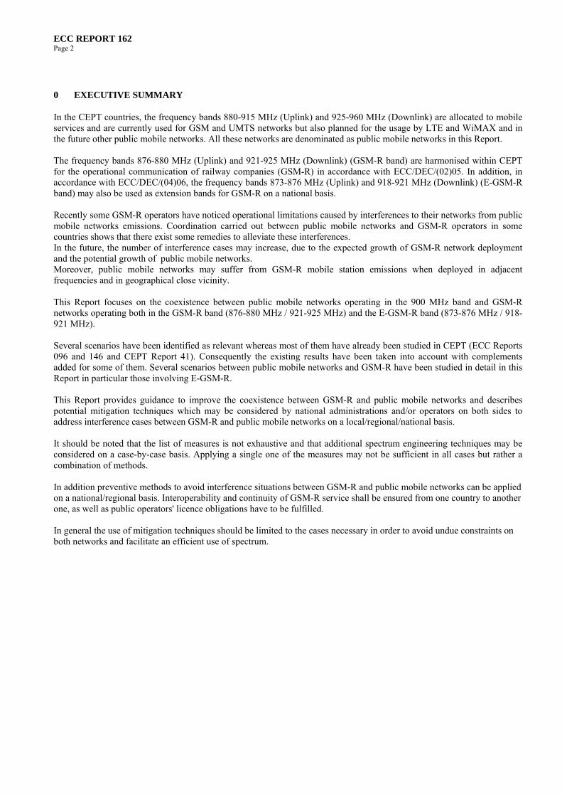
In the CEPT countries, the frequency bands 880-915 MHz (uplink) and 925-960 MHz (downlink) are harmonized for the usage of GSM and UMTS by a number of decisions such as ERC/DEC/(94)01 and ERC/DEC/(97)02, ECC/DEC/(06)13, EC Directive 2009/114 [3] and the EC Decision 2009/766/EC [4]. Furthermore, these bands are assumed to be used by other wideband systems like LTE and WiMAX. In this Report, the above mentioned networks are denominated as public mobile networks. The frequency bands 876-880 MHz (uplink) and 921-925 MHz (downlink) (GSM-R band) are harmonised within CEPT for the operational communication of railway companies (GSM-R) in accordance with ECC/DEC/(02)05. In addition, the frequency bands 873-876 MHz (uplink) and 918-921 MHz (downlink) (E-GSM-R) may also be used as extension bands for GSM-R on a national basis (ECC/DEC/(04)06).

ECC REPORT 162 Page 7
880 890
915
918 935 960873
921
E-GSM-R
876
downlinkuplink
925
GSM-R E-GSM-R
Public mobile networks Public mobile networks
GSM-RE-GSM-R
880 890
915
918 935 960873
921
E-GSM-R
876
downlinkuplink
925
GSM-R E-GSM-R
Public mobile networks Public mobile networks
GSM-RE-GSM-R
Figure 1: Main frequency usage within frequency range 873-960 MHz
It has to be noted that in some European countries the bands 870-876 MHz and 915-921 MHz are currently used by military systems (such as tactical radio relays); the compatibility between these systems and GSM-R is not addressed in this Report.
3 SYSTEM DESCRIPTION
3.1 Public mobile networks in the 900 MHz band
Originally, the 2nd generation mobile telephony system (GSM) was designed for voice services. This technology used the 900 MHz band, but today GSM is specified for a number of other frequency bands to support regional and national frequency allocations all over the world. It is the most popular standard for mobile telephony systems in the world. It is estimated that in the order of 75 % of the global mobile market uses this standard, meaning over 3.7+ billion connections across the globe (Q1 2010). Over the years, GSM has continued to develop, especially regarding data communication enhancements such as GPRS and EDGE enabling higher data rates. The 3rd generation mobile system UMTS was designed to enable voice and data services in addition to richer mobile multimedia services, including internet access. It started to be deployed in 2001, and by now has 300+ networks deployed, and the number of UMTS connections is estimated to be over 520 million including HSPA (Q1 2010). The next steps in the 3GPP standardisation of mobile communications systems are referred to as LTE (3GPP technology) and mobile WiMAX (IEEE technology). Based on existing 3GPP technologies (i.e. GSM, UMTS and LTE), requirements for MSR have been developed. MSR allows for a single RAT operation as well as simultaneous multi RAT operation. For single RAT scenarios, the MSR equipment would perform equal or better than the existing specifications while for multi RAT operation the emission mask requirements are based on UMTS spectrum emission mask. For LTE/MSR operating in the 900 MHz band, the emission mask was harmonized with UMTS. The objective is to ensure transparency regarding the interference created by unwanted emissions from 3GPP technologies towards adjacent systems. Broadband technologies present a lower spectral power density compared to narrow band technologies.
3.2 GSM-R
3.2.1 GSM-R application description
GSM-R constitutes the non-public networks of the European Railways that serve exclusively operational communication of railway companies. GSM-R supports services for train-network management such as command and control (data) of train traffic up to speeds of 500 km/h as well as corresponding speech communications. The GSM-R air-interface is based on the GSM standard.
ECC REPORT 162 Page 8
However, certain options are currently not used or cannot be used. It has also to be noted that the E-GSM-R band may not be available in certain CEPT countries. From a deployment point of view, GSM-R networks have almost a linear structure along the railway tracks. However, the locally higher traffic demand close to railway traffic nodes requires a higher network density which also implies a cellular frequency reuse. Command and control of a high number of remotely controlled fast running trains require nearly error-free data transfer and highly reliable radio transmission based on adequate radio resources. Following the license conditions GSM-R frequencies cannot be used, with certain exceptions, for public and commercial services.
The major European railway project, called ERTMS, aims at replacing the different national train control and command systems in Europe and contains currently two basic components:
ETCS, which is a radio based signalling system to replace the existing national ATP-systems
GSM-R.
In the future the deployment of ERTMS will enable a seamless European railway communication system for increasing European railway’s competitiveness, as demanded in EC Directives 96/48 [5] and 2001/16 [6].
3.2.2 GSM-R specific requirements
GSM-R networks have to fulfil tight availability and performance requirements of the railway radio services. The special conditions and requirements of a railway communication system such as the linear train movement along the tracks are laid down in the EIRENE SRS V15 specification. Both the line oriented GSM-R network and ERTMS requires a very high quality of service. Especially the application ETCS needs a permanent connection with a traffic load of 1 ERLANG per train and a permanent radio link availability of 100 % in time. These requirements of GSM-R and ETCS for continuous radio link availability are in accordance with the UIC/EC/EIRENE definitions. The minimum performance requirements for railway radio services based on GSM-R are defined in UIC EIRENE FRS V7 and SRS V15(May 2006). The documents are listed in Annex A of the Technical Specification for Interoperability Control Command and Signalling, based on EC Directives 96/48 [5] and 2001/16 [6]. The minimum coverage probability is defined as a probability value of at least 95% for any location interval of a length of 100m for which the measured signal level at the cab radio (train-mounted MS) antenna shall be higher or equal to the reference value of -92/-981 dBm depending on the service and on the speed of trains whereas for public mobile GSM networks uncorrelated locations are evaluated and the 95% criterion is averaged over all possible locations. According to the EIRENE specification for GSM-R systems the data transmissions for train control require an instantaneously available access in real-time. In spite of the above mentioned service differences between GSM-R and public mobile networks, the GSM-R air-interface is fully radio-compatible with the standard for GSM networks [14]. Noting that Directive 2008/57/EC of 17 June 2008 on the interoperability of the rail system within the Community shall be complied with, continuity of service of GSM-R shall also be ensured at borders. This means in particular that national measures intended to prevent or to mitigate interference between public mobile networks and GSM-R networks may not impede the cross-border operation of cab radios mounted in railway vehicles.
4 OBSERVATIONS AND CAUSES OF INTERFERENCE
Recently some GSM-R operators have noticed operational limitations caused by interferences to their networks from public mobile networks emissions. The majority of cases of GSM-R issues described so far are only involving GSM systems. Regarding the coexistence with wideband systems such as UMTS and LTE, interferences from UMTS900 to GSM-R have been reported in a limited number of cases.
1 These values differ from the planning levels that are used in practice. For further details, see Section 1.5 in Annex 1.
ECC REPORT 162 Page 9
The analysis of different measurement campaigns confirms that both blocking and intermodulation effects from public mobile networks (GSM) affect the operational performance of GSM-R service. It turned out that current GSM-R mobile stations are impacted by blocking and intermodulation effects when the interfering radio emissions exceed a signal level of around -40 dBm. This is consistent with the blocking/intermodulation levels defined in ETSI EN 301 502 for the first GSM channel. Interference cases were observed for both low and high GSM-R received signal strength. Some of the observed interferences may not be assigned to blocking and/or intermodulation, thus other effects, like wide-band noise have to be considered as possible sources. The relevant mechanisms by which interfering transmitters affect receivers are receiver desensitisation, receiver blocking, and receiver overload [13]. Receiver desensitization can be caused by different sources such as:
- unwanted emissions transmitted from various interferers
- IMP generated in the receiver - in particular 3rd and 5rd order IMPs - increasing the receiver noise floor.
- Power leakage from interfering signals due to limited receiver selectivity. In order to avoid a significant increase of the receiver noise floor causing receiver desensitization, unwanted emissions and IMPs should be sufficiently below the affected receiver noise floor. Receiver selectivity is the ability to isolate and acquire the desired signal from all of the undesired signals that may be present on other channels. Selectivity is a central factor in the control of adjacent channel interference2. Sensitivity is the measure of a receiver’s ability to receive signals of low strength. More sensitivity means a receiver can pick up lower level signals.3 Receiver blocking is the effect of a strong out-of-band interfering signal on the receiver's ability to detect a low level wanted signal. Receiver blocking response (or performance level) is defined as the maximum interfering signal level expressed in dBm reducing the specified receiver sensitivity by a certain number of dB's (usually 3 dB).Consequently, the receiver blocking response is normally evaluated at a wanted signal level which is 3 dB above the receiver sensitivity and at frequencies differing from that of the wanted signal. Receiver blocking of the GSM-R Mobile Station (i.e. train-mounted) is caused by:
high signal level received from public mobile network base stations and/or
by intermodulation products due to the wide receiver frequency range of the GSM-R Mobile Station (i.e. GSM-R/GSM Downlink 921 - 960 MHz) and
Limited blocking performance required by the respective ETSI specification for the GSM/GSM-R Mobile Station4.
Receiver overload is caused by too strong signals at the receiver antenna connector resulting in IMP in nonlinear part of the receiver chain. Additional information about the interference mechanisms can be found in the ERC Report 68 [26] and in the Annex 1 of the ECC Report 127 [27].
2 There are several ways to describe the selectivity of a radio receiver. One way is to simply give the bandwidth of the receiver over which its response level is within 3 dB of its response level at the centre frequency of the desired signal. This measure is often termed the “bandwidth over the -3dB points.” This bandwidth, however, is not necessarily a good means of determining how well the receiver will reject unwanted frequencies. Consequently, it is common to give the receiver bandwidth at two levels of attenuation; for example, -3dB and -60 dB. The ratio of these two bandwidths is called the shape factor. Ideally, the two bandwidths would be equal and the shape factor would be one. However, this value is very difficult to achieve in a practical circuit. 3 Greater sensitivity can also result in reception of unwanted signals at low levels that then must be eliminated or attenuated by the selectivity characteristics of the receiver. 4 Blocking performance is currently defined only for unmodulated CW signal.

ECC REPORT 162 Page 10
The reasons for operational impairment of GSM-R are mainly the cab-radio properties like receiver desensitisation and receiver blocking by public mobile GSM networks emissions. It should be noted that based on the defined service requirements the current GSM-R equipment has often no or limited frequency selectivity towards the 900 MHz allocation so that the cab-radio receiver is exposed to the GSM base station transmit signals without significant filtering.
5 COEXISTENCE SCENARIOS
This Report concerns the coexistence between GSM-R and public mobile networks in adjacent bands. For public mobile networks the following technologies are taken into account in this Report:
GSM (SC BTS & MCBTS)
UMTS (UTRA-FDD)
LTE (E-UTRA-FDD)/WiMAX The description of the different networks configurations should include all relevant parameters (receiver and transmitter characteristics of all systems), and differences in the deployments (linear versus full-area deployments). In Annex 1, the characteristics for all concerned technologies are given.
5.1 Principle interference scenarios between GSM-R and public mobile networks
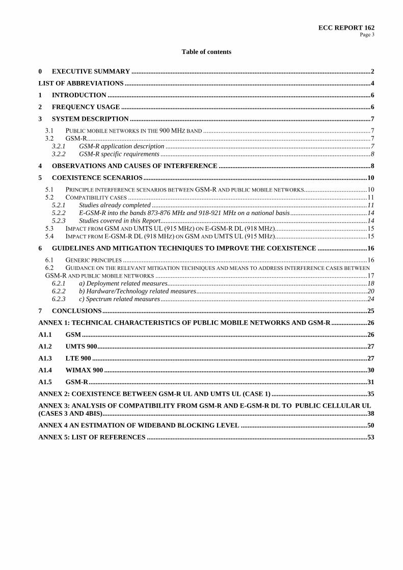
The main interference scenarios relevant to this Report are shown in Figure 2.
GSM-Rbase
station
Publicnetwork
basestation
GSM-Rmobilestation
Publicnetworkmobilestation
GSM-Rbase
station
Publicnetwork
basestation
GSM-Rmobilestation
Publicnetworkmobilestation
Figure 2: Principle interference scenarios
ECC REPORT 162 Page 11
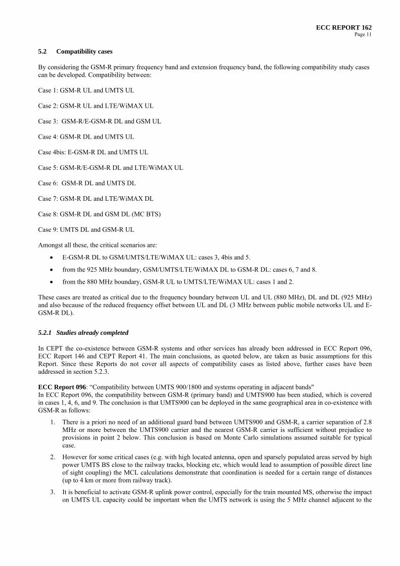
5.2 Compatibility cases
By considering the GSM-R primary frequency band and extension frequency band, the following compatibility study cases can be developed. Compatibility between: Case 1: GSM-R UL and UMTS UL Case 2: GSM-R UL and LTE/WiMAX UL Case 3: GSM-R/E-GSM-R DL and GSM UL Case 4: GSM-R DL and UMTS UL Case 4bis: E-GSM-R DL and UMTS UL Case 5: GSM-R/E-GSM-R DL and LTE/WiMAX UL Case 6: GSM-R DL and UMTS DL Case 7: GSM-R DL and LTE/WiMAX DL Case 8: GSM-R DL and GSM DL (MC BTS) Case 9: UMTS DL and GSM-R UL Amongst all these, the critical scenarios are:
E-GSM-R DL to GSM/UMTS/LTE/WiMAX UL: cases 3, 4bis and 5.
from the 925 MHz boundary, GSM/UMTS/LTE/WiMAX DL to GSM-R DL: cases 6, 7 and 8.
from the 880 MHz boundary, GSM-R UL to UMTS/LTE/WiMAX UL: cases 1 and 2. These cases are treated as critical due to the frequency boundary between UL and UL (880 MHz), DL and DL (925 MHz) and also because of the reduced frequency offset between UL and DL (3 MHz between public mobile networks UL and E-GSM-R DL).
5.2.1 Studies already completed
In CEPT the co-existence between GSM-R systems and other services has already been addressed in ECC Report 096, ECC Report 146 and CEPT Report 41. The main conclusions, as quoted below, are taken as basic assumptions for this Report. Since these Reports do not cover all aspects of compatibility cases as listed above, further cases have been addressed in section 5.2.3. ECC Report 096: “Compatibility between UMTS 900/1800 and systems operating in adjacent bands" In ECC Report 096, the compatibility between GSM-R (primary band) and UMTS900 has been studied, which is covered in cases 1, 4, 6, and 9. The conclusion is that UMTS900 can be deployed in the same geographical area in co-existence with GSM-R as follows:
1. There is a priori no need of an additional guard band between UMTS900 and GSM-R, a carrier separation of 2.8 MHz or more between the UMTS900 carrier and the nearest GSM-R carrier is sufficient without prejudice to provisions in point 2 below. This conclusion is based on Monte Carlo simulations assumed suitable for typical case.
2. However for some critical cases (e.g. with high located antenna, open and sparsely populated areas served by high power UMTS BS close to the railway tracks, blocking etc, which would lead to assumption of possible direct line of sight coupling) the MCL calculations demonstrate that coordination is needed for a certain range of distances (up to 4 km or more from railway track).
3. It is beneficial to activate GSM-R uplink power control, especially for the train mounted MS, otherwise the impact on UMTS UL capacity could be important when the UMTS network is using the 5 MHz channel adjacent to the
ECC REPORT 162 Page 12
GSM-R band. However, it has to be recognized that this is only applicable in low speed areas as elsewhere the use of uplink control in GSM-R will cause significantly increased call drop out rates.
4. In order to protect GSM-R operations, UMTS operators should take care when deploying UMTS in the 900 MHz band, where site engineering measures and/or better5 filtering capabilities (providing additional coupling loss in order to match the requirements defined for the critical/specific cases) may be needed in order to install UMTS sites close to the railway track when the UMTS network is using the 5 MHz channel adjacent to the GSM-R band.
It has to be noted that this study did not address tunnel coverage. Site sharing, which is expected to improve the coexistence, has not been studied either. For more details about the compatibility between UMTS900 and GSM-R see section 3.2 of the ECC Report 096. ECC Report 146: "Compatibility between GSM MCBTS and other services (TRR, RSBN/PRMG, HC-SDMA, GSM-R, DME, MIDS, DECT) operating in the 900 and 1800 MHz frequency bands" The compatibility between GSM MCBTS and GSM-R (primary band) has been analysed in the ECC Report 146 on GSM MCBTS coexistence with adjacent systems, which covers the case 8. In the conclusion the following is stated:
1. For the coexistence between GSM MCBTS and GSM-R, the MCL analysis indicates that under certain worst-case conditions the GSM-R network can experience interference, but also that the dominating interference effects are the blocking and adjacent channel performance of the GSM-R terminal. GSM-R terminals performances can be improved by additional filtering. The simulation analysis which also incorporates dynamic aspects of both networks show that the minimum required separation distances range between 20 meters and 55m, depending on the network assumptions. A carrier separation of 0.4 MHz (0.2 MHz between the edges of the channel) between GSM MC BTS and GSM-R as defined in ECC/DEC/(02)05 is thus sufficient to avoid harmful interference to GSM-R downlink due to unwanted emissions from a MCBTS.
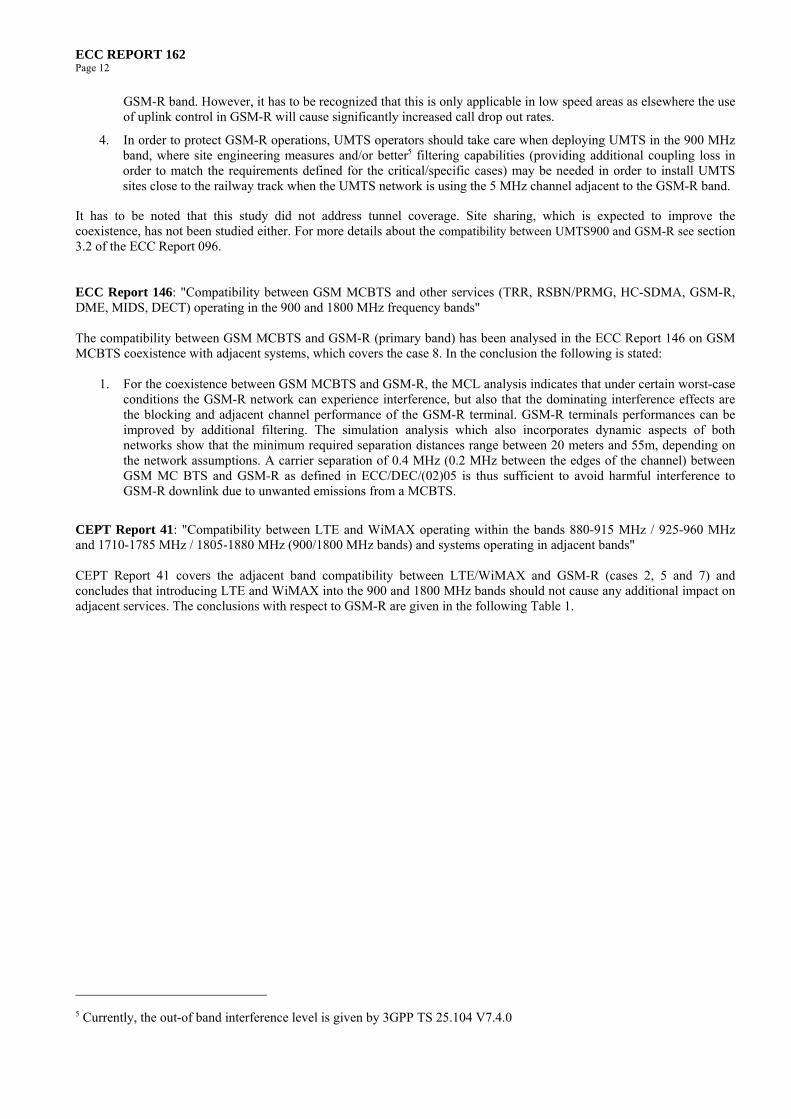
CEPT Report 41: "Compatibility between LTE and WiMAX operating within the bands 880-915 MHz / 925-960 MHz and 1710-1785 MHz / 1805-1880 MHz (900/1800 MHz bands) and systems operating in adjacent bands"
CEPT Report 41 covers the adjacent band compatibility between LTE/WiMAX and GSM-R (cases 2, 5 and 7) and concludes that introducing LTE and WiMAX into the 900 and 1800 MHz bands should not cause any additional impact on adjacent services. The conclusions with respect to GSM-R are given in the following Table 1.
5 Currently, the out-of band interference level is given by 3GPP TS 25.104 V7.4.0
ECC REPORT 162 Page 13
Band/Scenario (interferer >victim)
Summary Result
880 MHz/925 MHz LTE/WiMAX to GSM-R
In general, there is no need of an additional guard band between LTE/WiMAX900 and GSM-R whatever the channelization or bandwidth considered for LTE/WiMAX 900. ECC Report 096 concludes that a carrier separation of 2.8 MHz or more between the UMTS carrier and the nearest GSM-R carrier is sufficient. For LTE/WiMAX 900, the frequency separation between the nearest GSM-R channel centre frequency and LTE/WiMAX channel edge should be at least 300 kHz (at least 200 kHz between channel edges)
925 MHz - LTE/ WiMAX BS to GSM-R MS
For some critical cases (e.g. with high located antenna, open and sparsely populated areas served by high power LTE/WiMAX BS close to the railway tracks, which would lead to assumption of possible direct line of sight coupling) the MCL calculations demonstrate that coordination is needed for a certain range of distances (up to 4 km or more from railway track) when the GSM-R signal is close to the sensitivity level. In order to protect GSM-R operations, LTE/WiMAX operators should take care when deploying LTE/WiMAX in the 900 MHz band, where site engineering measures and/or better filtering capabilities (providing additional coupling loss in order to match the requirements defined for the critical/specific cases) may be needed in order to install LTE/WiMAX sites close to the railway track when the LTE/WiMAX network is using the channel adjacent to the GSM-R band. The deployment criteria of the GSM-R network such as the field strength level at the GSM-R cell edge could be also strengthened in order to improve the immunity of the GSM-R network towards the emissions from other systems.
880 MHz - GSM-R MS to LTE/WiMAX BS
It is beneficial to activate GSM-R uplink power control, especially for the train mounted MS, otherwise the impact on LTE/WiMAX capacity could be important when the LTE/WiMAX network is using the 10 MHz of spectrum adjacent to the GSM-R band. However, it has to be recognized that this is only applicable in low speed areas as elsewhere the use of uplink power control in GSM-R will cause significantly increased call drop out rates. Another solution would be to introduce a higher frequency separation between the GSM-R channel and the 900 MHz allocation by allowing transmission in the extended GSM-R band. However, this solution should be counter-balanced by the potential impact onto the upper part of the 900 MHz allocation. Due to the blocking response profile of LTE, the base station deployed above 890 MHz may also suffer from desensitisation due to E-GSM-R BS emissions.
915 MHz - LTE/ WiMAX MS to E-GSM-R MS (CEPT has recently adopted amendments to ECC/DEC/(02)05 on GSM-R and ECC/DEC/(04)06 on wideband PMR/PAMR. The amended Decisions provide a possibility for GSM-R extension (E-GSM-R) into the bands 873-876 MHz and 918-921 MHz on a national basis under the PMR/PAMR umbrella).
The LTE/WiMAX UE transmitting power is relatively small, at 23 dBm. In reality, mobile terminals rarely emit a maximum power of 23dBm (in 90% of cases they would emit 14 dBm or less [8]. By considering that the minimum coupling loss between UE and E-GSM-R BS is relatively large (80 dB is used in ECC Report 082 between UE and BS in rural area) compared to the MCL between LTE/WiMAX BS and GSM-R Train Mounted MS, and since the UE is moving, the interference from LTE/WiMAX UE to E-GSM-R MS should not lead to interference. For detailed analysis of interference between LTE/WiMAX UE to E-GSM-R MS, Monte-Carlo simulations should be performed; this is not covered in this Report.
ECC REPORT 162 Page 14
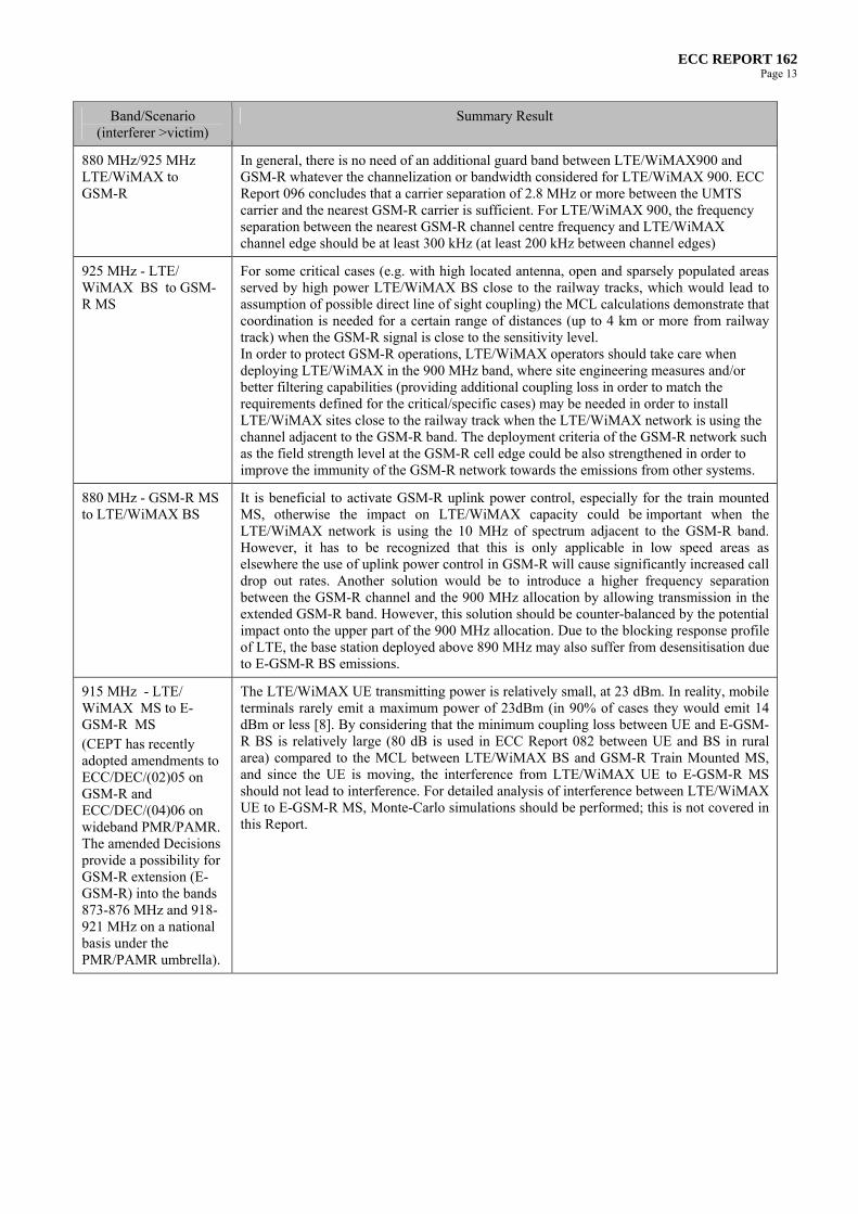
Band/Scenario (interferer >victim)
Summary Result
915 MHz - E-GSM-R BS to LTE/WiMAX BS (CEPT has recently adopted amendments to ECC/DEC/(02)05 on GSM-R and ECC/DEC/(04)06 on wideband PMR/PAMR. The amended Decisions provide a possibility for GSM-R extension (E-GSM-R) into the bands 873-876 MHz and 918-921 MHz on a national basis under the PMR/PAMR umbrella).
The worst interference case is the interference from E-GSM-R BS to LTE/WiMAX BS. The interference from E-GSM-R BS operating at frequencies above 918 MHz may cause receiver desensitisation and blocking of LTE/WiMAX900 BS operating below 915 MHz. The specifications of the GSM-R BTS characteristics in the expected extension band are assumed to be the same as those of GSM-R in the primary band. It is assumed the GSM-R BTS for extension band will be designed to protect efficiently the upper part of the uplink 900 MHz band, in particular the spurious emissions will be aligned to the spurious emissions as currently defined to protect the 900 MHz receive band. The main challenge would be to achieve this level in a 3 MHz offset instead of a 6 MHz frequency offset. However, as it would not be sufficient to prevent blocking of LTE/WiMAX base stations, the utilization of interference mitigation techniques should be assessed in order to protect efficiently LTE/WiMAX900 BS.
Table 1 : Main outcome of CEPT Report 41 (GSM-R section)
5.2.2 E-GSM-R into the bands 873-876 MHz and 918-921 MHz on a national basis
The E-GSM-R band was not taken into account within ECC Report 096 when UMTS was introduced into the 900/1800 MHz bands. However, the scenarios between GSM-R uplink (respectively UMTS uplink) and UMTS downlink (respectively GSM-R downlink), which are the scenarios impacted by the use of the E-GSM-R band, had not been addressed due the relatively large frequency separation (> 6 MHz). With the use of the E-GSM-R band, the frequency separation between LTE/WIMAX UL (880-915 MHz) and the E-GSM-R DL (918-921 MHz) is only 3 MHz at the minimum. Therefore the interference from E-GSM-R BS to UMTS/LTE/WiMAX BS receiver at 915 MHz (cases 3, 4bis and 5) is considered as a sensitive scenario.
5.2.3 Studies covered in this Report
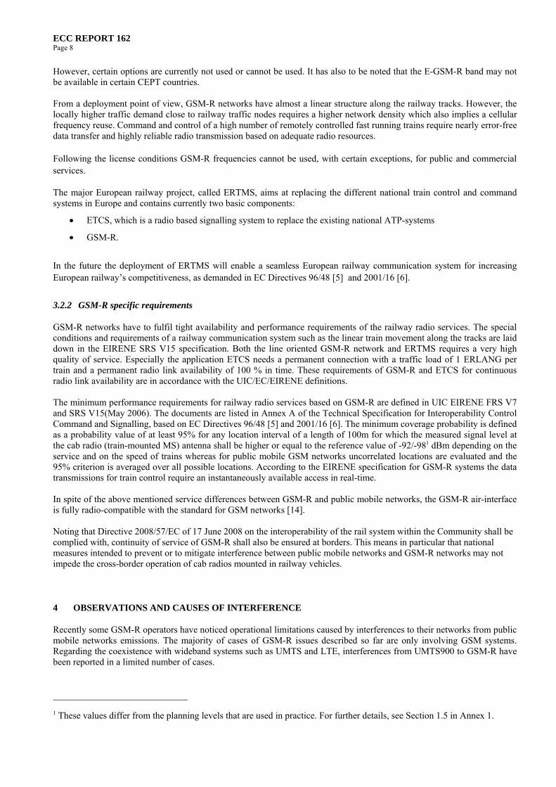
All the critical cases identified in section 5.2 have been already studied except cases 3 and 4bis. Case 3: Compatibility between E-GSM-R DL and GSM UL (see 5.3-5.4 and Annex 3 for the scenario GSM-R DLGSM UL). Case 4bis: Compatibility between E-GSM-R DL and UMTS UL (see 5.3-5.4 and Annex 3 for the scenario GSM-R DLUMTS UL).
873 876 880 915 918 921 925 960 GSM-R
UL extended
GSM-R UL
primary
Public mobile networks UL
GSM-R DL
extended
GSM-R DL
primary
Public mobile networks DL
Figure 3: Critical cases identified in section 5.2 and not studied in previous reports
In addition to ECC Report 096, Annex 2 of this Report deals with the impact of improving the blocking requirement of UMTS base stations. Annex 2 shows that even with such improved blocking profile, the GSM-R UL (close to 880 MHz) is capable of causing desensitisation of UMTS base stations. Therefore mitigation techniques are then needed to alleviate this difficulty.
Case 3 and case 4bis
ECC REPORT 162 Page 15
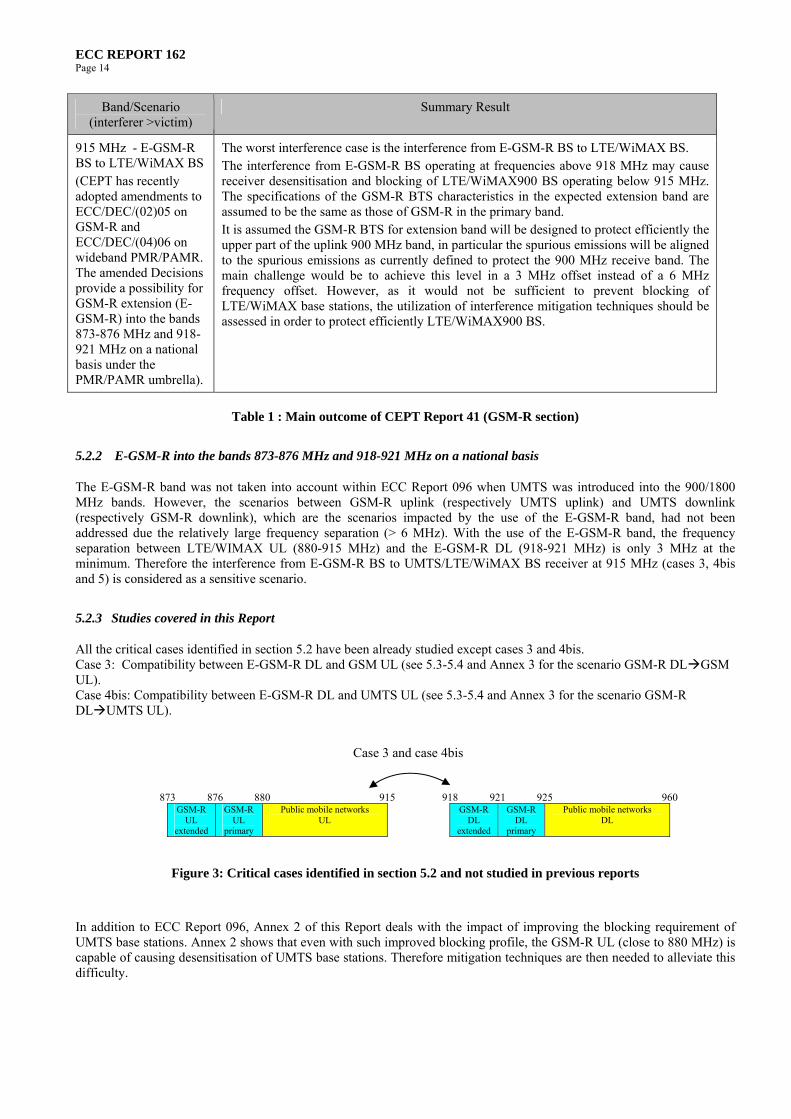
According to the calculations shown in Annex 4, it is expected that UMTS900 BS would suffer from blocking from GSM-R MS emissions (especially when the power control mechanism in GSM-R terminals is not used) before the GSM-R MS would be interfered by UMTS900 BS.
Annex 4 lets also determine that wideband systems compared to narrowband systems should decrease the risk of blocking within GSM-R terminals since the total interfering power allowed is higher for wideband systems (e.g. -27 dBm for UMTS900 and -29 dBm for LTE900) than for narrowband systems (e.g. -53 dBm for GSM900 with 5 TX).
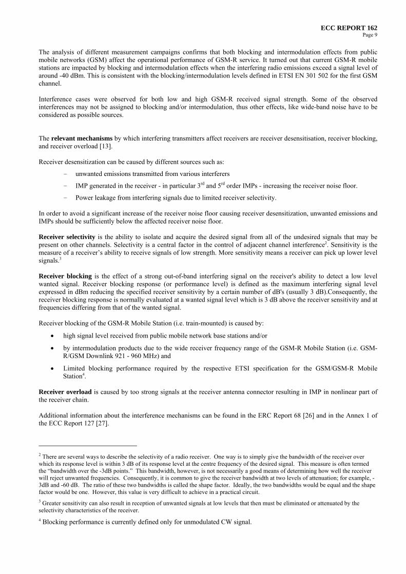
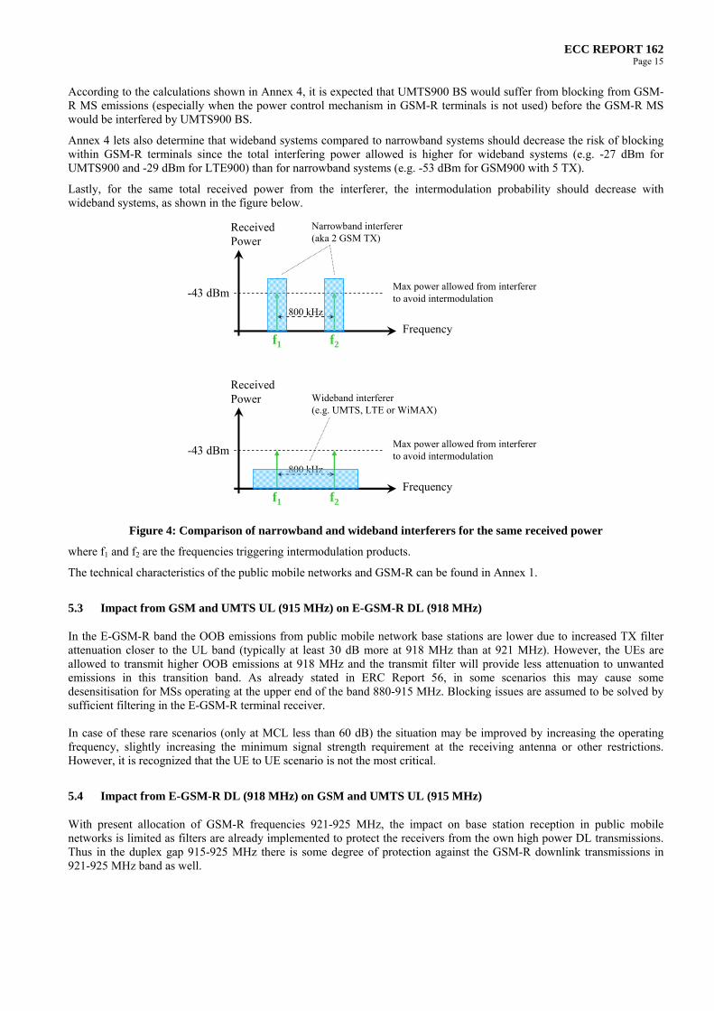
Lastly, for the same total received power from the interferer, the intermodulation probability should decrease with wideband systems, as shown in the figure below.
f1 f2
-43 dBm
ReceivedPower
Frequency
800 kHz
Max power allowed from interferer to avoid intermodulation
f1 f2
-43 dBm
ReceivedPower
Frequency
800 kHz
Max power allowed from interferer to avoid intermodulation
Narrowband interferer(aka 2 GSM TX)
Wideband interferer(e.g. UMTS, LTE or WiMAX)
Figure 4: Comparison of narrowband and wideband interferers for the same received power
where f1 and f2 are the frequencies triggering intermodulation products.
The technical characteristics of the public mobile networks and GSM-R can be found in Annex 1.
5.3 Impact from GSM and UMTS UL (915 MHz) on E-GSM-R DL (918 MHz)
In the E-GSM-R band the OOB emissions from public mobile network base stations are lower due to increased TX filter attenuation closer to the UL band (typically at least 30 dB more at 918 MHz than at 921 MHz). However, the UEs are allowed to transmit higher OOB emissions at 918 MHz and the transmit filter will provide less attenuation to unwanted emissions in this transition band. As already stated in ERC Report 56, in some scenarios this may cause some desensitisation for MSs operating at the upper end of the band 880-915 MHz. Blocking issues are assumed to be solved by sufficient filtering in the E-GSM-R terminal receiver. In case of these rare scenarios (only at MCL less than 60 dB) the situation may be improved by increasing the operating frequency, slightly increasing the minimum signal strength requirement at the receiving antenna or other restrictions. However, it is recognized that the UE to UE scenario is not the most critical.
5.4 Impact from E-GSM-R DL (918 MHz) on GSM and UMTS UL (915 MHz)
With present allocation of GSM-R frequencies 921-925 MHz, the impact on base station reception in public mobile networks is limited as filters are already implemented to protect the receivers from the own high power DL transmissions. Thus in the duplex gap 915-925 MHz there is some degree of protection against the GSM-R downlink transmissions in 921-925 MHz band as well.
ECC REPORT 162 Page 16
However, when the E-GSM-R band is used this protection is lower. OOB emissions will impact only networks using the frequencies in the upper part of the band 880-915 MHz and may be reduced by proper filtering at the E-GSM-R transmitting base station. Regarding blocking, the frequency band 915-925 MHz is defined as in-band. Thus the required blocking characteristics just outside the receive band are the same as in-band. In practice there is some additional protection from the transition region of the receive filter, which typically has 20-30 dB less attenuation at 918 MHz than at 921 MHz, increasing with increasing frequency. In addition, in the Annex 3, it is shown, through MCL calculations based upon the technical specifications, that the main problems experienced by public mobile networks operators would be the blocking of the UMTS BSs by the E-GSM-R BSs (the E-GSM-R BSs OOB emissions are negligible compared to the blocking of the UMTS BSs receivers). A number of mitigation options are available:
- Receiver characteristics: Improved receiver filter selectivity (external filtering and/or better receiver blocking characteristics)
- Coordination: The coordination of deployment with public mobile networks to improve the protection of the uplink in relevant areas, by site distance, reduced output power from E-GSM-R base station, additional filters, antenna pattern/direction etc.
It should be noted that reduced E-GSM-R BS transmit power implies shorter site-to-site distance to keep the signal/interference ratio sufficiently high. In order to not restrict the E-GSM-R base station output power, the total needed isolation has to be at least 93 dB for an output power of 45 dBm (see Annex 3 for details). Otherwise the E-GSM-R BS output power needs to be limited. The required isolation can be achieved by a combination of different measures, such as minimum site -to-site distance, additional filters at the victim base station or, appropriate choice of antenna patterns and direction. The available attenuation in the interfered base station will contribute as well. In case the public network base stations and E-GSM-R base stations are located close to each other, coordinated network deployment and operation should be carried out with the aim to agree on possible mitigation techniques between operators.
6 GUIDELINES AND MITIGATION TECHNIQUES TO IMPROVE THE COEXISTENCE
6.1 Generic principles
In case of interference to a network, the origin of the interference needs to be analyzed and clearly identified. At first the components of the interfered system have to be checked carefully (connectors, power amplifier, antennas, etc) Secondly, it is important to verify, that the problem is really caused by another network, and not within the interfered network (e.g. through co-channel interference, frequency planning, frequency reuse, an unexpectedly large coverage reach of individual cells, lack of coverage in specific areas, etc). It is essential to know if the interference is caused by performance characteristics of the interfered receiver or by emissions from other networks. Only by knowing the source of interference and understanding practical performance of radio equipment, appropriate mitigation techniques can be applied effectively. Any mitigation technique should be applied in the order of interference contribution, starting with the most dominating interference source. Coordination of sites, frequency planning etc. should always be considered. The application of mitigation techniques should be limited to the cases necessary in order to avoid undue constraints on both networks and to facilitate an efficient use of spectrum. It should be noted that some of the mitigation techniques listed in the tables below could imply relaxation in licensing obligations for public mobile network operators in areas close to railway tracks and thus may reduce the service provided by the public mobile networks.
The Report is also proposing some mitigation techniques that Administrations and/or operators could assess in order to ease the reuse of frequencies adjacent to GSM-R allocations – lower and upper parts of the 900 MHz band - by wide-band systems in the same geographical areas as GSM-R deployments.
ECC REPORT 162 Page 17
6.2 Guidance on the relevant mitigation techniques and means to address interference cases between GSM-R and public mobile networks
By applying mitigations techniques and various mechanisms to improve the coexistence between the GSM-R networks and public mobile networks it can be distinguished between the following options:
Reactive option: In case of interference: the administrations/operators (GSM-R and involved public mobile operators) are invited to coordinate their networks.
Preventive option: Prior to facing interference problems, a corridor along the railway tracks may be defined by national administrations. Within that corridor that should be limited as much as possible, a coordination would be carried out between the operators (GSM-R and involved public mobile operators) in order to prevent the interferences
With respect to the reactive option, the following information should be noted:
Solving interferences on a case by case basis
Setting a joint working group (at the national level) between GSM-R and public mobile networks representatives to solve interference cases effectively reported.
Solution already experienced in live networks
Generally speaking, this measure is the most appropriate in the countries where the number of reported interferences has been quite low so far.
With respect to the preventive option, the following information should be noted:
Coordination measure
Description Comment
Definition of a minimum isolation corridor to railway tracks (systematic increase of minimum coupling loss)
Definition of a minimum isolation corridor to railway tracks leads to a maximum acceptable interference level above the tracks (at a height of 4m).
If it is expected, that such values will be exceeded, an early coordination between the network operators is necessary.
Isolation corridors would be very challenging to implement. For example, in many countries there are requirements for coverage of public communication networks also in areas with railway tracks.
This measure would possibly lead to significantly reduced public GSM/UMTS coverage along railway tracks particularly in dense urban areas and thus run counter to the concept that GSM-R train radios should be able to roam on the public GSM network if the GSM-R network is unavailable.
This could be questionable regarding the European Directive [2] which is requesting that the development of a service should not impede the other services.
Difficult to monitor
Setting a coordination distance/area between the base stations of public mobile and GSM-R networks (railway tracks)
Setting a coordination distance between the base stations of public mobile networks and the railways is one possibility to avoid interference to GSM-R .It is intended that both GSM-R and public mobile network operators would coordinate any Mobile/base stations planned within a certain coordination area. A criterion corresponding to a receiving power level can be derived from the figures provided in EN 102 933 / EN 301 502 confirmed by practical measurements. (e.g.: -40 dBm/200 kHz for GSM
The definition of coordination corridors would be challenging to implement, and has to be done cooperatively between the GSM-R and public operators and should consider national distinctions.
Applying this as a general rule creates a significant co-ordination effort to both public and GSM-R operators, given the high number of the stations to be coordinated. Therefore, it is recognized that the relevance/efficiency of such a procedure strongly depends on the cases of interferences that occur.
Could limit the public operators' possibilities to fulfil their coverage requirements in areas with railway tracks.
Complex in dense population areas like big cities where both the density of railway tracks and public networks are very high. Might negatively impact public network coverage along railway tracks and ability of GSM-R train
ECC REPORT 162 Page 18
may be used as a criterion to trigger the coordination. This value is defined for a minimal receiving signal at -101 dBm (input to Mobile Terminal) for the GSM-R signal.)
radios to roam on the public GSM network.
Long implementation time because of the needed change in the regulators approval and coordination process as well as the according adoption of radio planning tool algorithms.
Generally speaking, the measure is not appropriate regarding the risk of interference, given the high number of base stations from public mobile networks to be coordinated.
Below, the mitigation techniques are divided into three different categories and also provided with comments. It provides a list of potential mitigation techniques which may be considered by national administrations and/or operators to address interference cases between GSM-R and public mobile networks once an interference situation has been identified.
It should be noted that:
this list is not exhaustive and that additional spectrum engineering techniques may be considered on a case-by-case basis;
applying only one of the listed measures may not be sufficient in all cases but rather a combination of them;
with a coordinated network planning some of the technical measures may not even be relevant.
The potential mitigation techniques are divided in the following categories:
a) Deployment related measures,
b) Hardware/Technology related measures, and
c) Spectrum related measures,
which are described in more detail in the following tables.
6.2.1 a) Deployment related measures
Mitigation technique
Description Comments
Increasing GSM-R field strength
The goal is to minimize the impact of unwanted emissions and to provide a sufficient C/I for the cab radio. It is recommended that the receive level at the GSM-R cab radio may not be lower than -92/-98 dBm (depending on the train speed) for an accumulated length of 5 m, measured by segments of 10 cm. The fore mentioned minimum field strength could be used for general planning for a first deployment. As for any mobile system there are possibly locations that need increase of signal strength due to local conditions, due to e.g. large number of interferers, dense deployment of the interfering base stations in dense traffic areas, urban environment, etc. The level of emitted power needs to be revised in such situations by adjusting e.g. output power, base station location, base station distance, antenna pattern etc.
If the method is used as a general method to improve the signal strength, the risk of introducing interference in the GSM-R or public network needs to be considered.
Minimum field strength is increased under certain local conditions such as dense deployments or dense traffic areas.
Can help in the limited case where GSM-R terminals are interfered and for which the GSM-R serving signal is close to the planning level; generally, a stronger carrier signal increases the immunity of the terminal towards out-of-band emissions.
Deployment of additional GSM-R base stations
Deployment of additional GSM-R base stations increases the network density and improves the overall coverage/field strength.
Coverage improvement for concerned areas
Additional hand-over zones caused by additional base stations have an impact on the resulting signalling and the QoS due to

ECC REPORT 162 Page 19
hand over failures (group calls and CSD are sensitive to handover at high speed).
There are some operational limitations for the deployment of additional base-stations.
Mid term solution (due to the time needed for the deployment of a site)
May not be possible in certain areas with limited frequency resources (e.g. dense urban railways areas)
Deployment of fixed GSM-R repeaters
Deployment of GSM-R repeater improves the signal level in a respective area.
Coverage improvement for concerned areas.
Extension of hand-over zones with a repeater has to be done very carefully to prevent cab radio from constant hand-over situations especially on high-speed lines.
There are some operational limitations for the deployment of repeater.
Mid term solution
Co-location of public mobile network and GSM-R base stations
Co-location of base stations for GSM-R and public mobile networks might reduce interference problems, in particular when the same technology is used.
Maybe limited in practice due to site constraints.
In general co-locating public and GSM-R BS will require similar Site-To-Site distances. This may not be given due to the different coverage and C/I requirements (in particular, when different services are used), and different access technologies.
Care needs to be taken for the GSM-R transmitter not to cause interference into the receive band of the co-located base station of a public mobile network, especially when the E-GSM-R band is used.
The output power of both systems needs to be in the same order of magnitude.
Antenna directing and down-tilt of public base station has to be planned carefully. In the specific scenario where the sites are co-located, the antennas of the two systems can be isolated by increasing the distances between the antennas on different vertical planes (horizontal distances).
Mid term solution
Output power reduction from public mobile network base stations
Output power reduction from public mobile network in respective areas will reduce the interference level received by GSM-R cab radio.
Will have major impact on coverage, capacity and service availability of the public networks
Reducing the GSM BS power would lead to reduced public GSM coverage along railway tracks and thus run counter to the concept that GSM-R train radios should be able to roam on the public GSM network if the GSM-R network is temporarily unavailable.
Short time solution
ECC REPORT 162 Page 20
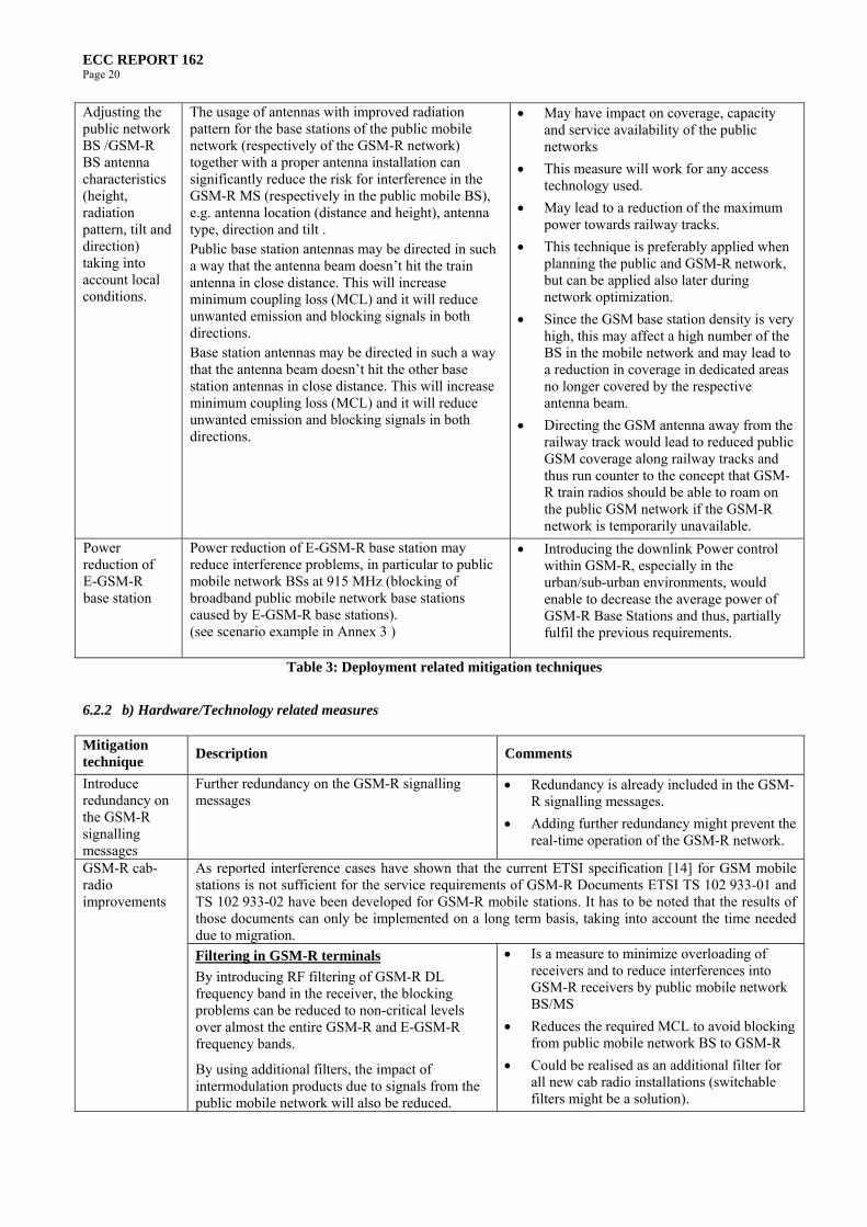
Adjusting the public network BS /GSM-R BS antenna characteristics (height, radiation pattern, tilt and direction) taking into account local conditions.
The usage of antennas with improved radiation pattern for the base stations of the public mobile network (respectively of the GSM-R network) together with a proper antenna installation can significantly reduce the risk for interference in the GSM-R MS (respectively in the public mobile BS), e.g. antenna location (distance and height), antenna type, direction and tilt . Public base station antennas may be directed in such a way that the antenna beam doesn’t hit the train antenna in close distance. This will increase minimum coupling loss (MCL) and it will reduce unwanted emission and blocking signals in both directions. Base station antennas may be directed in such a way that the antenna beam doesn’t hit the other base station antennas in close distance. This will increase minimum coupling loss (MCL) and it will reduce unwanted emission and blocking signals in both directions.
May have impact on coverage, capacity and service availability of the public networks
This measure will work for any access technology used.
May lead to a reduction of the maximum power towards railway tracks.
This technique is preferably applied when planning the public and GSM-R network, but can be applied also later during network optimization.
Since the GSM base station density is very high, this may affect a high number of the BS in the mobile network and may lead to a reduction in coverage in dedicated areas no longer covered by the respective antenna beam.
Directing the GSM antenna away from the railway track would lead to reduced public GSM coverage along railway tracks and thus run counter to the concept that GSM-R train radios should be able to roam on the public GSM network if the GSM-R network is temporarily unavailable.
Power reduction of E-GSM-R base station
Power reduction of E-GSM-R base station may reduce interference problems, in particular to public mobile network BSs at 915 MHz (blocking of broadband public mobile network base stations caused by E-GSM-R base stations). (see scenario example in Annex 3 )
Introducing the downlink Power control within GSM-R, especially in the urban/sub-urban environments, would enable to decrease the average power of GSM-R Base Stations and thus, partially fulfil the previous requirements.
Table 3: Deployment related mitigation techniques
6.2.2 b) Hardware/Technology related measures
Mitigation technique
Description Comments
Introduce redundancy on the GSM-R signalling messages
Further redundancy on the GSM-R signalling messages
Redundancy is already included in the GSM-R signalling messages.
Adding further redundancy might prevent the real-time operation of the GSM-R network.
GSM-R cab-radio improvements
As reported interference cases have shown that the current ETSI specification [14] for GSM mobile stations is not sufficient for the service requirements of GSM-R Documents ETSI TS 102 933-01 and TS 102 933-02 have been developed for GSM-R mobile stations. It has to be noted that the results of those documents can only be implemented on a long term basis, taking into account the time needed due to migration.
Filtering in GSM-R terminals
By introducing RF filtering of GSM-R DL frequency band in the receiver, the blocking problems can be reduced to non-critical levels over almost the entire GSM-R and E-GSM-R frequency bands.
By using additional filters, the impact of intermodulation products due to signals from the public mobile network will also be reduced.
Is a measure to minimize overloading of receivers and to reduce interferences into GSM-R receivers by public mobile network BS/MS
Reduces the required MCL to avoid blocking from public mobile network BS to GSM-R
Could be realised as an additional filter for all new cab radio installations (switchable filters might be a solution).
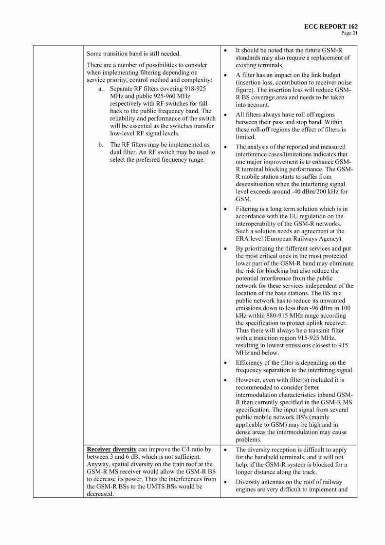
ECC REPORT 162 Page 21
Some transition band is still needed.
There are a number of possibilities to consider when implementing filtering depending on service priority, control method and complexity:
a. Separate RF filters covering 918-925 MHz and public 925-960 MHz respectively with RF switches for fall-back to the public frequency band. The reliability and performance of the switch will be essential as the switches transfer low-level RF signal levels.
b. The RF filters may be implemented as dual filter. An RF switch may be used to select the preferred frequency range.
It should be noted that the future GSM-R standards may also require a replacement of existing terminals.
A filter has an impact on the link budget (insertion loss, contribution to receiver noise figure). The insertion loss will reduce GSM-R BS coverage area and needs to be taken into account.
All filters always have roll off regions between their pass and stop band. Within these roll-off regions the effect of filters is limited.
The analysis of the reported and measured interference cases/limitations indicates that one major improvement is to enhance GSM-R terminal blocking performance. The GSM-R mobile station starts to suffer from desensitisation when the interfering signal level exceeds around -40 dBm/200 kHz for GSM.
Filtering is a long term solution which is in accordance with the EU regulation on the interoperability of the GSM-R networks. Such a solution needs an agreement at the ERA level (European Railways Agency).
By prioritizing the different services and put the most critical ones in the most protected lower part of the GSM-R band may eliminate the risk for blocking but also reduce the potential interference from the public network for these services independent of the location of the base stations. The BS in a public network has to reduce its unwanted emissions down to less than -96 dBm in 100 kHz within 880-915 MHz range according the specification to protect uplink receiver. Thus there will always be a transmit filter with a transition region 915-925 MHz, resulting in lowest emissions closest to 915 MHz and below.
Efficiency of the filter is depending on the frequency separation to the interfering signal
However, even with filter(s) included it is recommended to consider better intermodulation characteristics inband GSM-R than currently specified in the GSM-R MS specification. The input signal from several public mobile network BS's (mainly applicable to GSM) may be high and in dense areas the intermodulation may cause problems.
Receiver diversity can improve the C/I ratio by between 3 and 6 dB, which is not sufficient. Anyway, spatial diversity on the train roof at the GSM-R MS receiver would allow the GSM-R BS to decrease its power. Thus the interferences from the GSM-R BSs to the UMTS BSs would be decreased.
The diversity reception is difficult to apply for the handheld terminals, and it will not help, if the GSM-R system is blocked for a longer distance along the track.
Diversity antennas on the roof of railway engines are very difficult to implement and

ECC REPORT 162 Page 22
require at least 3 dB coupling loss due to the limited antenna place.
Enhanced GSM-R terminal receiver performance, offered by commercially available terminals such as Downlink Advanced Receiver Performance (DARP) and TIGHTER. These mobile classes offers link level performance improvements over an extensive range of services. DARP Phase I mobiles are commonly known as Single Antenna Interference Cancellation (SAIC) capable mobiles.
TIGHTER denotes a class of GERAN mobiles possessing enhanced receiver capabilities for CS, PS and control channels.
TIGHTER mobiles offer significant link level performance improvement for most GSM/EGPRS services and propagation conditions.
TIGHTER mobiles can significantly improve the robustness of the GSM-R DL operation
Among the advantages the capability to operate in higher interference environment could be useful to improve performance in high-traffic areas
DARP Phase I mobiles will not improve the blocking behaviour due to presence of one or more very strong input signals at the cab radio receiver.
There are various approaches to have a SAIC-enabled phone with different time scales and advantages.
GSM-R MS intermodulation performance
By Using additional filters, the impact of intermodulation products due to signals from the public mobile network will be reduced.
ETSI standards have to be adopted. (profile standard)
However, even with filter(s) included it is recommended to consider better intermodulation characteristics inband GSM-R than currently specified in the GSM-R MS specification. The input signal from several public mobile network BS's (mainly applicable to GSM) may be high and in dense areas the intermodulation may cause problems.
Replacement of the train mounted radio equipment with a newer generation with a higher overloading threshold
The limitation of GSM-R receiving bandwidth to the GSM-R allocation – or at least the implementation of two separate radio chains for GSM and GSM-R – has to be deeply assessed in order to reinforce the immunity of GSM-R terminals.
Compliance with ETSI specifications is sufficient for the required availability of GSM-R networks, but receiver parameters are for some situations at the limit. Documents ETSI TS 102 933-01 and TS 102 933-02 specify an improvement of the GSM-R receiver MS by 3 dB for the intermodulation threshold. This value may not be sufficient to cancel the interferences when they occur.
Long term solution due to long migration phase.
Slow frequency hopping in
GSM-R network
The available standard feature slow frequency hopping could be applied in the GSM-R network wherever possible, especially in urban areas to mitigate interference from public GSM networks in high-traffic areas.
For compensation of blocking effects in the GSM-R network caused by public GSM networks (with the E-GSM-R frequency band in principle possible, in those countries that have the condition to use the band).
In medium and slow train speed areas, frequency hopping will give a favourable fading diversity
Frequency Hopping is only applicable if

ECC REPORT 162 Page 23
enough GSM-R channels are available and is not possible for the carrier transmitting the BCCH.
Frequency hopping may be difficult to implement due to the required interoperability at the border.
Mid term solution Improved filters in public mobile network BS transmitters/ Change of UMTS BS receiver filters (increase the ACS)
Improved filters in public network BS transmitters to reduce the unwanted emissions. Filtering can be useful at the receiving UMTS base station to reduce blocking due to an E-GSM-R base station.
Public mobile network coverage area is reduced due to insertion loss of the filter.
An improved filter at the transmitter would limit the OOB emissions but not the in-band emissions (IM3). This improves adjacent channel compatibility but not blocking and overloading phenomena.
However filter design is challenging; attention must be given to the error vector magnitude requirement for the receiver. It would be necessary to assess the feasibility and the impact of such filtering requirement in terms of UMTS performance capabilities bearing in mind that manufacturers are proposing node Bs with capabilities improved from the standard requirements (noting that the improvement of the characteristics of real equipments compared to the standards are confidential and manufacturer dependant).
Short / mid term solution
Frequency hopping
Slow frequency hopping in public networks The more frequencies in the sequence the better the interference situation
BCCH frequencies in areas close to the railway should be selected from the available frequencies that are not close to the GSM-R frequencies, i.e. only hopping traffic channels should occur close to GSM-R frequencies.
Already commonly used in public networks as a standard feature
Short term solution Discontinuous Transmission (DTX)
Activation of DTX will significantly lower the interference levels in GSM networks.
With DTX activated for GSM no radio blocks will be transmitted in a CS connection during periods of silence. This will significantly reduce interference levels in GSM networks and in adjacent systems.
Downlink Power Control in public networks
Downlink Power Control mechanism operating on active Traffic channels.
Reduces statistically the overall interference level
At the moment, radio carriers with BCCH and other Broadcast information cannot be used with downlink power control (ongoing studies in GERAN).
Introduction of the Power Control mechanism in GSM-R
Downlink Power Control
The Downlink Power Control mechanism in the GSM-R network would enable to decrease the average power of GSM-R Base Stations and thus, reduce interferences.
Would help to prevent desensitisation of public mobile base stations in the same geographical environment.
However GSM-R networks normally operate without power control to ensure that any broadcast messages reach all mobile

ECC REPORT 162 Page 24
stations. Note: in a GSM network (on which model a GSM-R network is based), the broadcast channel BCCH cannot be power controlled: the GSM specifications enable the power control for the others channels (traffic channel: TCH) for the mobiles but also for the base stations.
Uplink power control
Uplink power control of GSM-R radio transmitter is proposed according to the ECC Reports (096 and 146) when the train is slowly moving or standing still.
At low speed the feature is easily applied as this is a standard feature.
Using power control in group calls is theoretically possible, but needs additional effort.
At high speed, the possibility to adapt the power fast enough may be too small without increasing the risk for dropping the call. But in this case the induced interference is of short duration.
Short/mid term solution Table 4: Hardware and technology related mitigation techniques
6.2.3 c) Spectrum related measures
Mitigation technique
Description Comments
Coordinated frequency planning of GSM-R network and public mobile networks
Coordination of the frequency planning would enable operators to avoid conflicts on the radio interface between adjacent base stations.
Due to the high number of public base stations difficult to realize in dense urban or urban areas due to tight frequency plan.
High effort to implement/defined the overall process incl. adaption of tools, data exchange, etc.
Frequency separation of the used frequency of public Base stations close to railway tracks avoids interference.
Choice of BCCH frequencies for GSM-R and public GSM networks : In areas close to railways the BCCH frequencies of the public GSM networks should be selected from channels not close to the GSM-R bands.
Due to the high number of public base stations difficult to realize in dense urban or urban areas.
Difficult to realise if public GSM operator at lower end of band has only limited number of channels available
Would similarly apply if GSM-R BCCH frequencies would be placed away from the public GSM band.
Use of the E-GSM-R band
It is preferable to use the E-GSM-R band for TCH and the GSM-R band for BCCH and TCH, noting that the power control mechanism can only be activated on the TCH.
BCCH cannot be placed in the E-GSM-R band. This band will not be used in a harmonized way in various CEPT countries. The usage of this band may be based on a “hot-spot” usage (need for more traffic).
No interoperability to countries not implementing E-GSM-R so far.
May be used as a mitigation technique in the case of interference to GSM-R with a second TX transmitting the TCH (only if GSM-R is applied with two TXs or more per site)
The use of the E-GSM-R frequency band might bring more flexibility for the frequency planning.
Table 5: Spectrum related mitigation techniques
ECC REPORT 162 Page 25
7 CONCLUSIONS
This Report focuses on the coexistence between public mobile networks operating in the 900 MHz band and GSM-R networks operating both in the GSM-R band (876-880 MHz / 921-925 MHz) and in the E-GSM-R band (873-876 MHz / 918-921 MHz). On one side, some GSM-R operators have recently noticed and/or reported operational limitations caused by interferences to their networks from public mobile networks emissions. The majority of interferences to GSM-R are attributed to GSM systems. Interferences from UMTS900 to GSM-R have also been reported in a limited number of cases. Coordination carried out between public mobile networks and GSM-R operators in some countries shows that there exist some remedies to alleviate these interferences. Moreover, theoretical calculations showed that, compared to GSM systems, public wideband systems such as UMTS, LTE and WiMAX may decrease the risk of blocking and intermodulation (due to lower spectral density) into GSM-R terminal receivers. On the other side, calculations have shown that public mobile networks, especially wideband systems, may suffer from GSM-R mobile station emissions when deployed in adjacent frequencies and in geographical close vicinity. The actual absence of wideband systems deployed directly in adjacent frequencies to E-GSM-R allocation has so far prevented interferences from GSM-R to wideband public mobile networks. As a consequence, investigations and studies have been carried out in order to understand what the difficulties are and what solutions could be applied in order to ensure the coexistence of systems. Several scenarios have been identified as relevant whereas most of them have already been studied in CEPT (ECC Reports 096 and 146 and CEPT Report 41). Consequentially, the existing results have been taken as a basis for this Report but with some additions. Three scenarios have been identified as the most sensitive:
The scenario between public mobile networks UL (915 MHz) and E-GSM-R DL (918 MHz). It turned out that public mobile network BS’s located in close vicinity to E-GSM-R BS’s may experience desensitisation due to the emissions coming from these E-GSM-R BS’s.
The scenario between public mobile networks DL (at 925 MHz) and GSM-R/E-GSM-R DL. For this scenario it turned out that public mobile network BS´s located in the surrounding neighbourhood of railway tracks may desensitise, block or generate IMP inside the receiver chain of the train mounted cab radio, despite the application of a guard channel of 200 kHz as defined in Decision ECC(02)05. Several interference cases have already been reported in some countries.
The scenario between public mobile wideband networks UL and GSM-R UL (at 880 MHz) . It turned out that public mobile wideband network BS’s located in close vicinity to GSM-R may experience desensitisation due to the emissions coming from the GSM-R terminals.
This Report provides guidance to improve the coexistence between GSM-R and public mobile networks and describes potential mitigation techniques which may be considered by national administrations and/or operators on both sides to address interference cases between GSM-R and public mobile networks on a local/regional/national basis. It should be noted that the list of measures is not exhaustive and that additional spectrum engineering techniques may be considered on a case-by-case basis. Applying a single one of the measures may not be sufficient in all cases but rather a combination of methods. In addition preventive methods to avoid interference situations between GSM-R and public mobile networks can be applied on a national/regional basis. Interoperability and continuity of GSM-R service shall be ensured from one country to another one, as well as public operators' licence obligations have to be fulfilled. In general the use of mitigation techniques should be limited to the cases necessary in order to avoid undue constraints on both networks and facilitate an efficient use of spectrum.
ECC REPORT 162 Page 26
ANNEX 1: TECHNICAL CHARACTERISTICS OF PUBLIC MOBILE NETWORKS AND GSM-R
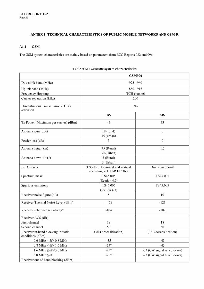
A1.1 GSM
The GSM system characteristics are mainly based on parameters from ECC Reports 082 and 096.
Table A1.1: GSM900 system characteristics
GSM900
Downlink band (MHz) 925 - 960
Uplink band (MHz) 880 - 915
Frequency Hopping TCH channel
Carrier separation (kHz) 200
Discontinuous Transmission (DTX) activated
No
BS MS
Tx Power (Maximum per carrier) (dBm) 43
33
Antenna gain (dBi) 18 (rural) 15 (urban)
0
Feeder loss (dB) 3 0
Antenna height (m) 45 (Rural) 30 (Urban)
1.5
Antenna down-tilt (°) 3 (Rural) 3 (Urban)
-
BS Antenna 3 Sector, Horizontal and vertical according to ITU-R F1336.2
Omni-directional
Spectrum mask TS45.005 (Section 4.2)
TS45.005
Spurious emissions TS45.005 (section 4.3)
TS45.005
Receiver noise figure (dB) 8 10
Receiver Thermal Noise Level (dBm) 121 -121
Receiver reference sensitivity* -104 -102
Receiver ACS (dB) First channel Second channel
18 50
18 50
Receiver in-band blocking in static conditions (dBm)
(3dB desensitization) (3dB desensitization)
0.6 MHz ≤ δf <0.8 MHz -35 -43
0.8 MHz ≤ δf <1.6 MHz -25* -43
1.6 MHz ≤ δf <3.0 MHz -25* -33 (CW signal as a blocker)
3.0 MHz ≤ δf -25* -23 (CW signal as a blocker)
Receiver out-of-band blocking (dBm)

ECC REPORT 162 Page 27
Fc <860 MHz +8 0
860 MHz < Fc < 905 MHz (inband) 0
905 MHz < Fc < 915 MHz (inband) -5
915 MHz < Fc < 925 MHz (inband) (inband)
925 MHz < Fc < 935 MHz 0 (inband)
935 MHz < Fc < 980 MHz +8 (inband)
Fc> 980 MHz +8 0
Receiver in-band blocking
Cell radius (km) 2.4 (rural) 0.6 (urban 1) 1.4 (urban 2)
2.4 (rural) 0.6 (urban 1) 1.4 (urban 2)
Number of carriers per BTS 4 (typical)
Frequency separation between carriers (For worst case the last carrier placed at the edge of the transmit band)
600 kHz
* In addition -16 dBm is specified for 12 dB desensitization.
A1.2 UMTS 900
The UMTS900 system parameters have been extracted from CEPT Report 42. UMTS900 technical specifications have been developed by 3GPP in release 8 [20-21]. The main characteristics are summarized in Table A1.2 below:
Table A1.2: UMTS system characteristics
UMTS 900 Downlink band (MHz) 925 – 960
Uplink band (MHz) 880 – 915 Carrier separation (MHz) 5
Channel raster (kHz) 200 BS UE
Tx Power (Maximum) (dBm) 43 21
Maximum Antenna gain (dBi) 18 (rural) 15 (urban)
0
Feeder loss (dB) 3 0
Antenna height (m) 45 (Rural) 30 (Urban)
1.5
Antenna down-tilt (°) 3 - Spectrum mask TS25.104 [12] TS25.101 [7]
Spurious emissions TS25.104 [12] TS25.101 [7] Occupied Bandwidth (MHz) - 99% 3.84 3.84
Receiver Temperature (KBT) -108 dBm -108 dBm Receiver noise figure 5 dB 12 dB
Receiver Thermal Noise Level -103 dBm -96 dBm Receiver reference sensitivity -121 -114
Receiver in-band blocking TS25.104 [12] TS25.101 [7] Receiver out-of-band blocking TS25.104 [12] TS25.101 [7]
Elevation antenna pattern Recommendation ITU-R F.1336-2 Omni-directional
Vertical aperture 8° (Gmax = 18 dBi)
16° (Gmax = 15 dBi) Not applicable
Azimuth antenna pattern tri-sectorized Omni-directional Horizontal aperture 65° Not applicable
polarization Slant N.A
A1.3 LTE 900
The LTE900 system parameters have been extracted from CEPT Report 40.

ECC REPORT 162 Page 28
Table A1.3: LTE900 system parameters
LTE900
Downlink band (MHz) 925 – 960
Uplink band (MHz) 880 – 915
Carrier separation (MHz)/ carrier bandwidth/ resource blocks
1.4/1.08/6 3/2.7/15 5/4.5/25 10/9/50
15/13.5/75 20/18/100
Channel raster (kHz) 100
BS UE
Tx Power (Maximum) (dBm)
43 23
Antenna gain (dBi) 18 (rural) 15 (urban)
0
Feeder loss (dB) 3 0
Antenna height (m) 45 (Rural) 30 (Urban)
1.5
Antenna down-tilt (°) 3 (Urban) 3 (Rural)
-
BS-UE MCL (dB) 80 (Rural) 70 Urban)
-
Spectrum mask Section A1.1 of CEPT Report 40
(Ref. TS36.104/ EN301908-14)
Section A1.2 of CEPT Report 40 (Ref. TS36.101/ EN301908-13)
ACLR_1 (First adjacent channel) (dB)
45 (LTE & UMTS channel BWs)
Section A1.3 of CEPT Report 40 (Ref. TS36.104/ EN301908-14)
30 (LTE channel BWs)
33 (3.84 MHz) Section A1.4 of CEPT Report 40 (Ref. TS36.101/ EN301908-13)
ACLR_2 (Second adjacent channel (dB)
45 dB (LTE & UMTS channel BWs)
Section A1.3 of CEPT Report 40 (Ref. TS36.104/ EN301908-14)
36 (LTE channel BWs)
36 (3.84 MHz)
Section A1.4 of CEPT Report 40 (Ref. TS36.101/ EN301908-13)
Spurious emissions Section A1.5 of CEPT Report 40 (Ref. TS36.104/ EN301908-14)
Section A1.6 of CEPT Report 40 (Ref. TS36.104/ EN301908-14)
Receiver Bandwidth (MHz) 1.08
2.7
4.5
1.08
2.7
4.5
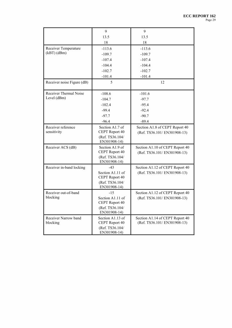
ECC REPORT 162 Page 29
9
13.5
18
9
13.5
18
Receiver Temperature (kBT) (dBm)
-113.6
-109.7
-107.4
-104.4
-102.7
-101.4
-113.6
-109.7
-107.4
-104.4
-102.7
-101.4
Receiver noise Figure (dB) 5 12
Receiver Thermal Noise Level (dBm)
-108.6
-104.7
-102.4
-99.4
-97.7
-96.4
-101.6
-97.7
-95.4
-92.4
-90.7
-89.4
Receiver reference sensitivity
Section A1.7 of CEPT Report 40 (Ref. TS36.104/ EN301908-14)
Section A1.8 of CEPT Report 40 (Ref. TS36.101/ EN301908-13)
Receiver ACS (dB) Section A1.9 of CEPT Report 40 (Ref. TS36.104/ EN301908-14)
Section A1.10 of CEPT Report 40 (Ref. TS36.101/ EN301908-13)
Receiver in-band locking -43 Section A1.11 of CEPT Report 40 (Ref. TS36.104/ EN301908-14)
Section A1.12 of CEPT Report 40 (Ref. TS36.101/ EN301908-13)
Receiver out-of-band blocking
-15 Section A1.11 of CEPT Report 40 (Ref. TS36.104/ EN301908-14)
Section A1.12 of CEPT Report 40 (Ref. TS36.101/ EN301908-13)
Receiver Narrow band blocking
Section A1.13 of CEPT Report 40 (Ref. TS36.104/ EN301908-14)
Section A1.14 of CEPT Report 40 (Ref. TS36.101/ EN301908-13)
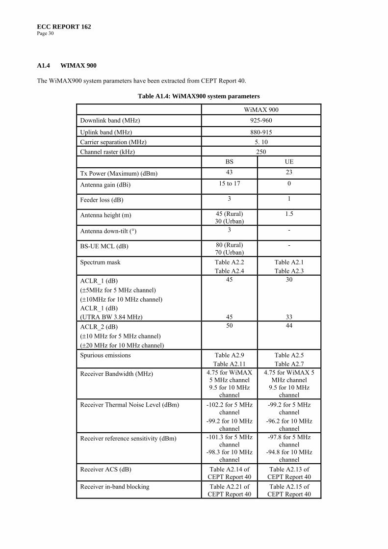
ECC REPORT 162 Page 30
A1.4 WIMAX 900
The WiMAX900 system parameters have been extracted from CEPT Report 40.
Table A1.4: WiMAX900 system parameters
WiMAX 900
Downlink band (MHz) 925-960
Uplink band (MHz) 880-915
Carrier separation (MHz) 5. 10
Channel raster (kHz) 250
BS UE
Tx Power (Maximum) (dBm) 43 23
Antenna gain (dBi) 15 to 17 0
Feeder loss (dB) 3 1
Antenna height (m) 45 (Rural) 30 (Urban)
1.5
Antenna down-tilt (°) 3 -
BS-UE MCL (dB) 80 (Rural) 70 (Urban)
-
Spectrum mask Table A2.2 Table A2.4
Table A2.1 Table A2.3
ACLR_1 (dB)
(5MHz for 5 MHz channel)
(10MHz for 10 MHz channel) ACLR_1 (dB) (UTRA BW 3.84 MHz)
45
45
30
33
ACLR_2 (dB)
(10 MHz for 5 MHz channel)
(20 MHz for 10 MHz channel)
50
44
Spurious emissions Table A2.9 Table A2.11
Table A2.5 Table A2.7
Receiver Bandwidth (MHz) 4.75 for WiMAX 5 MHz channel 9.5 for 10 MHz
channel
4.75 for WiMAX 5 MHz channel
9.5 for 10 MHz channel
Receiver Thermal Noise Level (dBm) -102.2 for 5 MHz channel
-99.2 for 10 MHz channel
-99.2 for 5 MHz channel
-96.2 for 10 MHz channel
Receiver reference sensitivity (dBm) -101.3 for 5 MHz channel
-98.3 for 10 MHz channel
-97.8 for 5 MHz channel
-94.8 for 10 MHz channel
Receiver ACS (dB) Table A2.14 of CEPT Report 40
Table A2.13 of CEPT Report 40
Receiver in-band blocking Table A2.21 of CEPT Report 40
Table A2.15 of CEPT Report 40
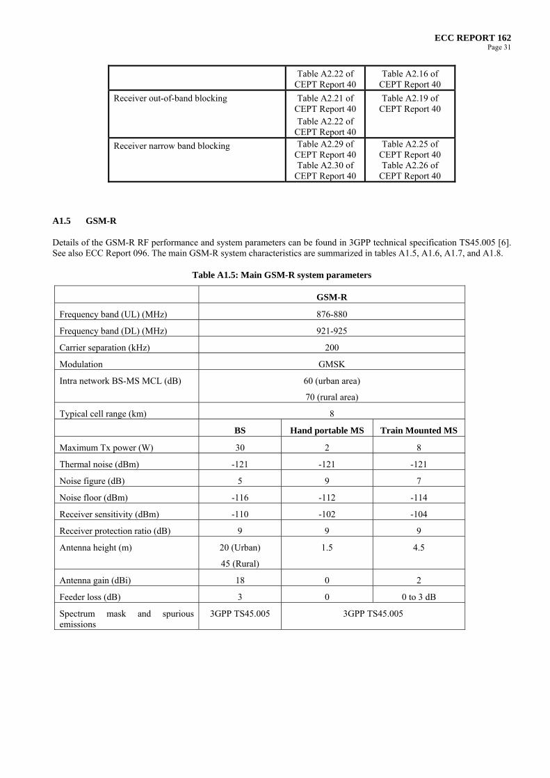
ECC REPORT 162 Page 31
Table A2.22 of CEPT Report 40
Table A2.16 of CEPT Report 40
Receiver out-of-band blocking Table A2.21 of CEPT Report 40 Table A2.22 of
CEPT Report 40
Table A2.19 of CEPT Report 40
Receiver narrow band blocking Table A2.29 of CEPT Report 40 Table A2.30 of
CEPT Report 40
Table A2.25 of CEPT Report 40 Table A2.26 of
CEPT Report 40
A1.5 GSM-R
Details of the GSM-R RF performance and system parameters can be found in 3GPP technical specification TS45.005 [6]. See also ECC Report 096. The main GSM-R system characteristics are summarized in tables A1.5, A1.6, A1.7, and A1.8.
Table A1.5: Main GSM-R system parameters
GSM-R
Frequency band (UL) (MHz) 876-880
Frequency band (DL) (MHz) 921-925
Carrier separation (kHz) 200
Modulation GMSK
Intra network BS-MS MCL (dB) 60 (urban area)
70 (rural area)
Typical cell range (km) 8
BS Hand portable MS Train Mounted MS
Maximum Tx power (W) 30 2 8
Thermal noise (dBm) -121 -121 -121
Noise figure (dB) 5 9 7
Noise floor (dBm) -116 -112 -114
Receiver sensitivity (dBm) -110 -102 -104
Receiver protection ratio (dB) 9 9 9
Antenna height (m) 20 (Urban)
45 (Rural)
1.5 4.5
Antenna gain (dBi) 18 0 2
Feeder loss (dB) 3 0 0 to 3 dB
Spectrum mask and spurious emissions
3GPP TS45.005 3GPP TS45.005
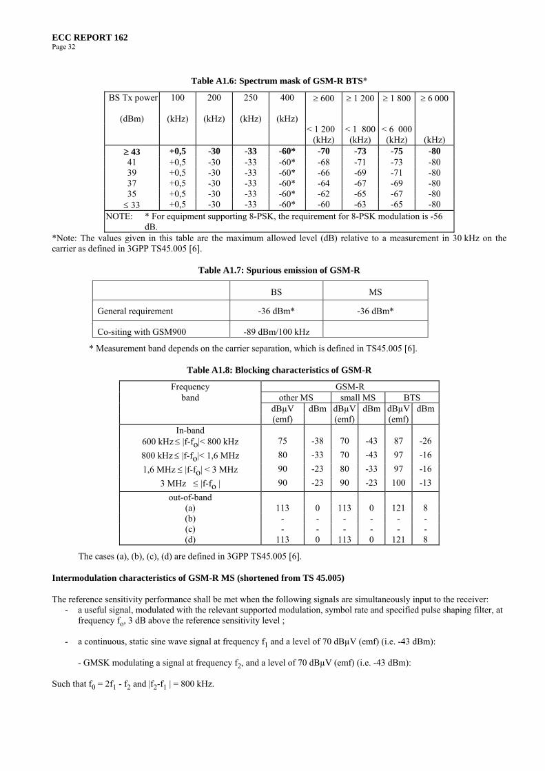
ECC REPORT 162 Page 32
Table A1.6: Spectrum mask of GSM-R BTS*
BS Tx power
(dBm)
100
(kHz)
200
(kHz)
250
(kHz)
400
(kHz)
600 1 200 1 800 6 000
< 1 200 (kHz)
< 1 800(kHz)
< 6 000 (kHz)
(kHz)
43 +0,5 -30 -33 -60* -70 -73 -75 -80 41 +0,5 -30 -33 -60* -68 -71 -73 -80 39 +0,5 -30 -33 -60* -66 -69 -71 -80 37 +0,5 -30 -33 -60* -64 -67 -69 -80 35 +0,5 -30 -33 -60* -62 -65 -67 -80 33 +0,5 -30 -33 -60* -60 -63 -65 -80
NOTE: * For equipment supporting 8-PSK, the requirement for 8-PSK modulation is -56 dB.
*Note: The values given in this table are the maximum allowed level (dB) relative to a measurement in 30 kHz on the carrier as defined in 3GPP TS45.005 [6].
Table A1.7: Spurious emission of GSM-R
BS MS
General requirement -36 dBm* -36 dBm*
Co-siting with GSM900 -89 dBm/100 kHz
* Measurement band depends on the carrier separation, which is defined in TS45.005 [6].
Table A1.8: Blocking characteristics of GSM-R
Frequency GSM-R band other MS small MS BTS
dBµV dBm dBµV dBm dBµV dBm (emf) (emf) (emf)
In-band 600 kHz |f-fo|< 800 kHz 75 -38 70 -43 87 -26
800 kHz |f-fo|< 1,6 MHz 80 -33 70 -43 97 -16
1,6 MHz |f-fo| < 3 MHz 90 -23 80 -33 97 -16
3 MHz |f-fo | 90 -23 90 -23 100 -13
out-of-band (a) 113 0 113 0 121 8 (b) - - - - - - (c) - - - - - - (d) 113 0 113 0 121 8
The cases (a), (b), (c), (d) are defined in 3GPP TS45.005 [6].
Intermodulation characteristics of GSM-R MS (shortened from TS 45.005)
The reference sensitivity performance shall be met when the following signals are simultaneously input to the receiver: - a useful signal, modulated with the relevant supported modulation, symbol rate and specified pulse shaping filter, at
frequency fo, 3 dB above the reference sensitivity level ;
- a continuous, static sine wave signal at frequency f1 and a level of 70 dBµV (emf) (i.e. -43 dBm):
- GMSK modulating a signal at frequency f2, and a level of 70 dBµV (emf) (i.e. -43 dBm):
Such that f0 = 2f1 - f2 and |f2-f1 | = 800 kHz.

ECC REPORT 162 Page 33
GSM-R network planning principles
According to EIRENE definitions, the receive level at the GSM-R cab radio may not be lower than -92/-98 dBm (depending for the train speed) for an accumulated length of 5 m, measured by segments of 10 cm. The possibility to revise the minimal field strength is already contained in EIRENE SRS v15: "The values for ETCS levels 2/3 concerning coverage and speed-limitations are to be validated and, if necessary, reviewed after the first operational implementation of ETCS." In practice, the GSM-R networks like other cellular networks are planned with a radio network planning tool and appropriate propagation models. The planning tool uses information from digital terrain maps as required for the propagation model to achieve most accurate prediction for signal levels. The propagation model gives mean signal levels on network level. Even with the use of optimized propagation models there is still some inaccuracy in the signal predictions and this inaccuracy is compensated with certain margin to achieve needed minimum signal level. This margin is commonly called shadow fading margin and with this margin the needed minimum signal level is achieved at every cell edge with the selected probability. Shadow fading is Gaussian distributed and it can be derived from the standard deviation of the model tuning error and the wanted probability. For example, a standard deviation of the propagation model tuning error of 6.1 dB and a wanted probability at cell edge of 95 %, results in a shadow margin of 10 dB. If the minimum signal level of GSM-R network is -98 dBm then planning level is -88 dBm. In practice this means that mean value for signal levels over the network at cell edges are -88 dBm but in some cell edges are reach or even under -98 dBm signal level. With 95 % probability signal level is at least -98 dBm at cell edge in this example. For optimized propagation models constant factors such as polarization losses of cross polarized antennas can be included. The following figure is providing one example of the possible vertical diagram of a GSM-R cab-radio antenna. The directivity of such an antenna has an impact on the interfering signal received from the public network since the antenna gain is reduced by 5 dB for an angle of 30°.
Figure A1.1: Vertical diagram of a GSM-R train-mounted antenna

ECC REPORT 162 Page 34
α = 30°
Figure A1.2: Configuration of deployment

ECC REPORT 162 Page 35
ANNEX 2: COEXISTENCE BETWEEN GSM-R UL AND UMTS UL (CASE 1)
In this Annex addressing the coexistence between GSM-R UL and UMTS UL, the most critical scenario is the impact of emissions coming from GSM-R terminals onto the mobile base stations deployed above 880 MHz. It is assumed a UMTS BS deployed in the first 5 MHz of the E-GSM sub-allocation. Compared to the ECC Report 096, the following analysis is developed. Note that in the 3GPP specification, UMTS base station blocking performance is defined against GSM-R MS UL signal assuming that 8 time slots of GSM TDMA frame are occupied.
Table A2.1: Blocking performance requirements of UMTS BS
Operating band
Center frequency of interfering signal
Interfering signal mean power
Wanted signal mean power
Minimum offset of interfering signal
Type of interfering signal
II 1850-1910 MHz -47 dBm -115 dBm ±2.7 MHz GMSK modulated* III 1710-1785 MHz -47 dBm -115 dBm ±2.8 MHz GMSK modulated* IV 1710-1755 MHz -47 dBm -115 dBm ±2.7 MHz GMSK modulated* V 824-849 MHz -47 dBm -115 dBm ±2.7 MHz GMSK modulated* VIII 880-915 MHz -47 dBm -115 dBm ±2.8 MHz GMSK modulated* X 1710-1770 MHz -47 dBm -115 dBm ±2.7 MHz GMSK modulated* XII 698-716 MHz -47 dBm -115 dBm ±2.7 MHz GMSK modulated* XIII 777-787 MHz -47 dBm -115 dBm ±2.7 MHz GMSK modulated* XIV 788-798 MHz -47 dBm -115 dBm ±2.7 MHz GMSK modulated* NOTE*: GMSK modulation as defined in TS45.004[5] Some manufacturers are capable to provide base stations for which the blocking requirements are 10 dB better than the 3GPP specifications It would mean that the real UMTS base station would meet a blocking level of -37 dBm for the first adjacent GSM-R channel. As it was done for ECC Report 096 and ECC Report 146, the blocking phenomenon is assessed for a base station closed to the railway line. It should be noted that the previous figures (-47 dBm) are defined with a 6 dB desensitisation for UMTS900 BS. However, mobile operators as well as GSM—R operators do not tolerate such desensitisation. The 1 dB desensitisation is equivalent to a blocking level of -52 dBm.
Figure A2.1: Interference scenario between GSM-R MS and UMTS BS
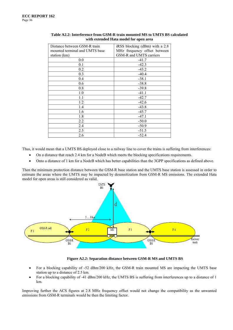
ECC REPORT 162 Page 36
Table A2.2: Interference from GSM-R train mounted MS to UMTS BS calculated with extended Hata model for open area
Distance between GSM-R train mounted terminal and UMTS base station (km)
iRSS blocking (dBm) with a 2.8 MHz frequency offset between GSM-R and UMTS carriers
0.0 -41.7 0.1 -42.3 0.2 -43.2 0.3 -40.4 0.4 -38.1 0.6 -38.8 0.8 -39.8 1.0 -41.1 1.1 -42.7 1.2 -42.6 1.4 -43.8 1.6 -45.7 1.8 -47.1 2.2 -50.0 2.4 -50.9 2.5 -51.5 2.6 -52.4
Thus, it would mean that a UMTS BS deployed close to a railway line to cover the trains is suffering from interferences:
On a distance that reach 2.4 km for a NodeB which meets the blocking specifications requirements.
Onto a distance of 1 km for a NodeB which has better capabilities than the 3GPP specifications as defined above. Then the minimum protection distance between the GSM-R base station and the UMTS base station is assessed in order to estimate the areas where the UMTS may be impacted by desensitization from GSM-R MS emissions. The extended Hata model for open areas is still considered as valid.
Figure A2.2: Separation distance between GSM-R MS and UMTS BS
For a blocking capability of -52 dBm/200 kHz, the GSM-R train mounted MS are impacting the UMTS base station up to a distance of 2.5 km.
For a blocking capability of -41 dBm/200 kHz, the UMTS BS is suffering from interferences up to a distance of 1 km.
Improving further the ACS figures at 2.8 MHz frequency offset would not change the compatibility as the unwanted emissions from GSM-R terminals would be then the limiting factor.

ECC REPORT 162 Page 37
As the UMTS base stations are implementing duplexer, their selectivity profile should be improved when the frequency offset is increased between the GSM-R and UMTS carrier. It would mean that a higher frequency offset would solve the issue of interferences from GSM-R train mounted onto UMTS base stations. Of course, the implementation of power Control mechanism would be beneficial as well to reduce interferences onto UMTS BS. The analysis can be duplicated with LTE profile as both technologies present equivalent blocking characteristics.
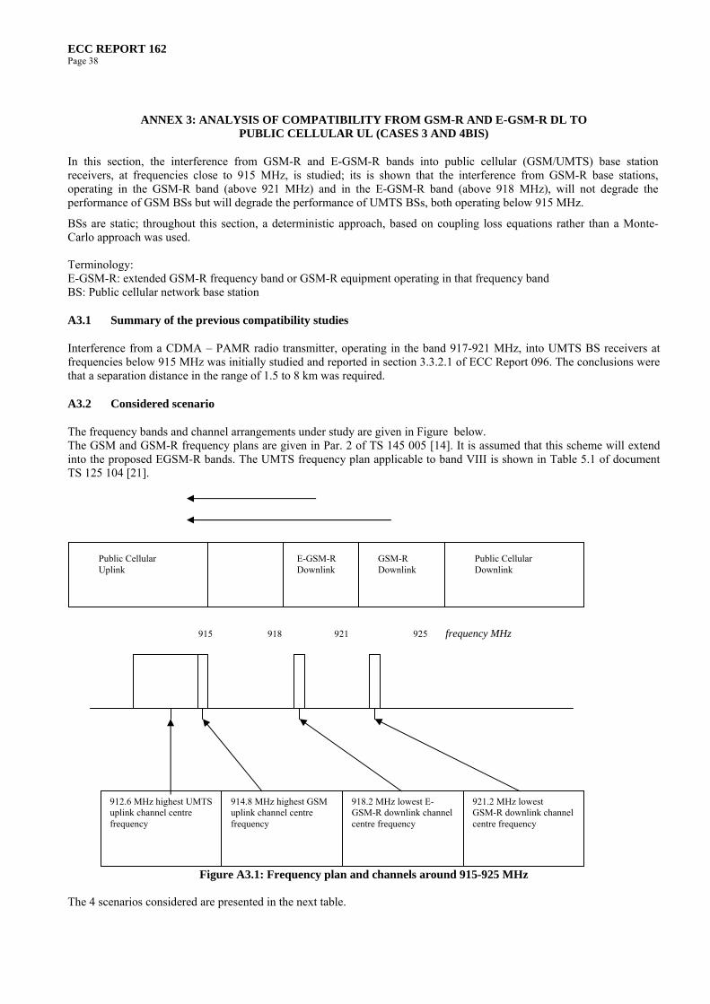
ECC REPORT 162 Page 38
ANNEX 3: ANALYSIS OF COMPATIBILITY FROM GSM-R AND E-GSM-R DL TO PUBLIC CELLULAR UL (CASES 3 AND 4BIS)
In this section, the interference from GSM-R and E-GSM-R bands into public cellular (GSM/UMTS) base station receivers, at frequencies close to 915 MHz, is studied; its is shown that the interference from GSM-R base stations, operating in the GSM-R band (above 921 MHz) and in the E-GSM-R band (above 918 MHz), will not degrade the performance of GSM BSs but will degrade the performance of UMTS BSs, both operating below 915 MHz.
BSs are static; throughout this section, a deterministic approach, based on coupling loss equations rather than a Monte-Carlo approach was used. Terminology: E-GSM-R: extended GSM-R frequency band or GSM-R equipment operating in that frequency band BS: Public cellular network base station
A3.1 Summary of the previous compatibility studies
Interference from a CDMA – PAMR radio transmitter, operating in the band 917-921 MHz, into UMTS BS receivers at frequencies below 915 MHz was initially studied and reported in section 3.3.2.1 of ECC Report 096. The conclusions were that a separation distance in the range of 1.5 to 8 km was required.
A3.2 Considered scenario
The frequency bands and channel arrangements under study are given in Figure below. The GSM and GSM-R frequency plans are given in Par. 2 of TS 145 005 [14]. It is assumed that this scheme will extend into the proposed EGSM-R bands. The UMTS frequency plan applicable to band VIII is shown in Table 5.1 of document TS 125 104 [21].
Figure A3.1: Frequency plan and channels around 915-925 MHz
The 4 scenarios considered are presented in the next table.
918.2 MHz lowest E-GSM-R downlink channel centre frequency
921.2 MHz lowest GSM-R downlink channel centre frequency
912.6 MHz highest UMTS uplink channel centre frequency
914.8 MHz highest GSM uplink channel centre frequency
915 918 921 925 frequency MHz
Public Cellular Uplink
E-GSM-R Downlink
GSM-R Downlink
Public Cellular Downlink
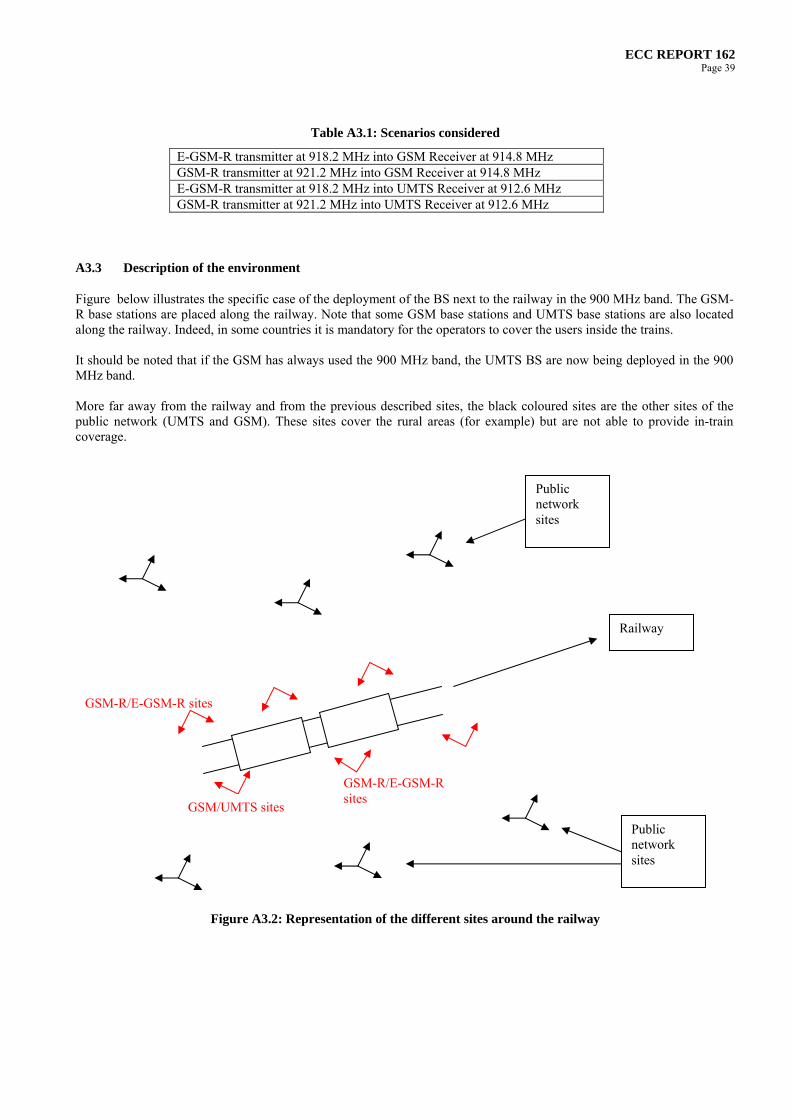
ECC REPORT 162 Page 39
Table A3.1: Scenarios considered
E-GSM-R transmitter at 918.2 MHz into GSM Receiver at 914.8 MHz GSM-R transmitter at 921.2 MHz into GSM Receiver at 914.8 MHz E-GSM-R transmitter at 918.2 MHz into UMTS Receiver at 912.6 MHz GSM-R transmitter at 921.2 MHz into UMTS Receiver at 912.6 MHz
A3.3 Description of the environment
Figure below illustrates the specific case of the deployment of the BS next to the railway in the 900 MHz band. The GSM-R base stations are placed along the railway. Note that some GSM base stations and UMTS base stations are also located along the railway. Indeed, in some countries it is mandatory for the operators to cover the users inside the trains. It should be noted that if the GSM has always used the 900 MHz band, the UMTS BS are now being deployed in the 900 MHz band. More far away from the railway and from the previous described sites, the black coloured sites are the other sites of the public network (UMTS and GSM). These sites cover the rural areas (for example) but are not able to provide in-train coverage.
Figure A3.2: Representation of the different sites around the railway
Railway
Public network sites
GSM/UMTS sites
GSM-R/E-GSM-R sites
GSM-R/E-GSM-R sites
Public network sites

ECC REPORT 162 Page 40
A3.4 Method to calculate the maximum interfering power at a receiver input
The interference power at a receiver input can be expressed in terms of erosion of the receiver sensitivity. By definition, an degradation of receiver sensitivity (in dB) is equal to the increase in the total noise plus interference (in dB). The receiver noise floor without interference is given by If the receiver sensitivity is degraded by η dB then the interference plus noise power is given by Therefore the interference power () at the receiver input is given by: where is the degradation of receiver sensitivity (dB) due to the interference power, KT = -174 dBm/Hz, B is the bandwidth in Hz and NF is the receiver noise figure. This formula is applied below for the case of a GSM900 and UMTS900 victim for a degradation of receiver sensitivity () of 0.5 and 1 dB.
Table A3.2: Derivation of permitted interference power at a receiver input (in the band of the receiver input)
GSM UMTS
KT dBm/Hz -174 -174 -174 -174
B Hz 200000 200000 3840000 3840000
NF dB 8 8 5 5
KTB + NF dBm -113 -113 -103 -103
Degraded receiver sensitivity η
dB 0.5 1.0 0.5 1.0
interference power γ dBm -122.1 -118.9 -112.3 -109.0
A3.5 Methodology to calculate receiver OOB emissions into the victim receiver
TS 145 005 describes the out of band emissions that will arise from GSM transmitters in the frequency bands 918 – 960 MHz. Note that from section 4.2.1 (2nd sentence) the emissions mask does not apply beyond the relevant transmit band ± 2 MHz.
KTB NF η KTB NF
10 1010γ 10.Log 10 10 dBm
KTB NF η
10 1010 10 mW
KTB NF
1010 mW
η
1 01 0γ K T B N F + 1 0 .L o g 1 0 1 d B m
ECC REPORT 162 Page 41
From TS 145 005 Par 4.3.2.1 (page 31, middle table) the output power from a GSM-R BTS in the BTS receiving band is less than -89 dBm. The BTS receiving band is confirmed as 876-915 MHz from case (xi) of section 2 of TS 145 005. This simplifies the calculation, since the OOB band power from a GSM-R BTS consists of a constant level independent of frequency or output power.
In any bandwidth POOBTx = -89 + 10.Log(Channel BW/100 kHz) where POOBTx is the power presented to the antenna feeder at the transmitter due to OOB emissions and Channel BW is the bandwidth of the victim channel (200 kHz or 5000 kHz) It should be noted that the same simplification cannot be applied to a UMTS transmitter; par 6.6.3 of TS 125 104 specifies that the OOB emission requirement applies at frequency offsets greater than 12.5 MHz beyond the highest or lowest carrier frequency. Therefore studies such as those contained in ECC Report 096 are required to take account of the UMTS emissions mask.
A3.6 Methodology to calculate receiver Adjacent Channel Selectivity
ACS can be derived from the blocking level. The blocking level is normally described as normal receiver operation when an interference level of I is applied simultaneously with a wanted signal of RxSensitivity + η. Therefore the applied interference may be referred to the receiver input at the receiver input to give rise to an erosion of receiver sensitivity of η dB. The receiver Adjacent Channel Selectivity can be derived from the appropriate equipment specification or from the blocking level. This is normally specified as a wanted signal level at which the normal receiver characteristics shall be maintained, when in addition an interferer of a given power is applied. For a GSM BS receiver, clause 5.1 of ETSI TS 145 005 gives the blocking specification. This states that channel performance shall be maintained for a wanted signal 3 dB above the reference sensitivity when an interfering signal, of -16 dBm for 800 kHz<Δf<3 MHz and -16 dBm for Δf > 3 MHz, is applied. The interference effectively degrades the receiver sensitivity by 3 dB. For a UMTS900 BS receiver, clause 7.4.1 of TS 125 104 gives the receiver adjacent channel selectivity. This states that a Bit Error Ratio (BER) of 0.001 shall be maintained for a wanted signal of -115 dBm and a Wideband Code Division Multiple Access (WCDMA) modulated interfering signal 5 MHz off set (i.e. in the band 915 - 920 MHz), with mean power -52 dBm. The wanted signal is 6 dB above the reference sensitivity, therefore the interferer effectively degrades the receiver sensitivity by 6 dB. Table 7.4 of TS 125.104 (Case viii) gives the blocking specification for a UMTS900 BS receiver. This states that a BER of 0.001 shall be maintained for a wanted signal of -115 dBm and a WCDMA modulated interfering signal 10 MHz off set (i.e. in the band 920 - 921 MHz), with mean power -40 dBm. The wanted signal is 6 dB above the reference sensitivity; therefore the interferer effectively degrades the receiver sensitivity by 6 dB. Table 7.5 of TS 125.104 (Case viii), gives the blocking specification for a UMTS900 BS receiver. This states that a BER of 0.001 shall be maintained for a wanted signal of -115 dBm and a narrow band modulated interfering signal 2.8 MHz off set, with mean power -47 dBm. The wanted signal is 6 dB above the reference sensitivity; therefore the interferer effectively degrades the receiver sensitivity by 6 dB. NOTE: Although the blocking specification for a narrow band interfering signal is defined only for frequencies 880-915 MHz in TS 125.104, the blocking signal performance is assumed to be the same or better for 915-925 MHz. This assumption is based on the fact that the requirements for WCDMA modulated interferer in the same specification is constant for the whole range 880-925 MHz. The ACS is given by:
ACS= Pinterferer -10.Log(1.38.10-23.290.BHz) – nf -30 - 10.Log(10(M/10) - 1) (Equation 1)
where :
Pinterferer is the applied interference BHz is the receive channel bandwidth in Hz nf is the receiver noise figure in dB

ECC REPORT 162 Page 42
M = wanted signal – RF sens in dB Table A3.3 below shows the calculation of the ACS for GSM and UMTS as victim and considering different frequency offset with the interferer.
Table A3.3: Calculated values of ACS
Victim System GSM GSM UMTS UMTS UMTS Interferer frequency range (MHz)
915.6<F<917.8
F>917.8 915<F<920 920<F<925 F>915 (narrow band interferer)
REF Sens -104 -104 -121 -121 -121 wanted signal -101 -101 -115 -115 -115 Pinterferer -16 -13 -52 -40 -47 (1) M = wanted signal - RF sens 3 3 6 6 6 BS nf 8 8 5 5 5 B 2.00E+05 2.00E+05 3.84E+06 3.84E+06 3.84E+06 PN=10*log(1.38e-23*290*B)+NF+30
-112.967 -112.967 -103.134 -103.134 -103.134
P interference allowed in the band = PN+10*log(10^(M/10)-1)
-112.988 -112.988 -98.390 -98.390 -98.390
ACS=Pinterferer-P interference allowed in the band
97.0 100.0 46.4 58.4 51.4
(1): table 7.5 of doc 25104 for wide area BS. Minimum offset of interfering signal: 2.8 MHz. The ACS for the scenarios under consideration can therefore be deduced from the Table A3.3:
Table A3.4: ACS for the scenarios considered
Interferer frequency (MHz)
Interferer system
Victim frequency (MHz)
Victim system ACS (dB)
921.2 GSM-R 914.8 GSM 100
918.2 E-GSM-R 914.8 GSM 97
921.2 GSM-R 912.6 UMTS 58
918.2 E-GSM-R 912.6 UMTS 46
918.2 E-GSM-R 912.6 UMTS 51 (considering
the interferer as narrow band)
Limitations of this approach: The method of presenting the value of ACS has been used in other ECC Reports, for example in ECC Report 086 [22] Table 1 and page 27 of ECC Report 096 [12]. However, the limitations of this technique for calculating the true value of ACS should be recognised. The ACS value is derived from the blocking level, the blocking level is normally described as normal receiver operation when an interference level of I is applied simultaneously with a wanted signal of RxSensitivity + η. Therefore the applied interference is assumed to increase the total noise plus interference by η dB. The interference is normally applied at a relatively high level, we suggest that several mechanisms will be happening at the receiver.
1. Genuine selectivity; the interfering signal will be attenuated by some amount, or only some portion of the interfering signal will pass through the filter chain and appear as interface at the demodulator input

ECC REPORT 162 Page 43
2. Mixer saturation, such that the gain of the front end, is reduced. 3. Self Intermodulation of the interfering signal so that the part of the interfering signal energy is thrown into the wanted channel. That is, if a signal of band width f1 to f2 encounters a non linearity then intermodulation products will be generated in the regions f2 to 2*f2-f1 and f1 to 2*f1-f2; the bandwidth of the intermodulation product is f2-f1. The lower products could lie in the bandwidth of an adjacent receiver
These 3 mechanisms act together to erode the receiver sensitivity. However in the more general case where interference is not at a high level only the genuine ACS will be effective. The current equipment specifications do not give an easy method for extracting the genuine ACS. Furthermore in the general case it is necessary to know the ACS for a CW narrow band interferer then the ACS for an interferer spanning f1 to f2 will be given by:
2
1
ACS( f )f10
f2 1
ACS 10.Logf f
110 df
Although the limitation of ACS calculations is acknowledged, the values given in Table A3.4 are presented as a reasonable approximation.
A3.7 General method for calculating the effect of interference across a frequency boundary
In this paragraph, a general method for calculating the effect of an interferer on a nearby receiver is developed based on a summation of the power due to out of band emission and Adjacent Channel Selectivity. Notice that this is different to the often used method of treating blocking and out of band emissions independently, which has a number of limitations:
Blocking and out of band emissions may relate to different degradations of receiver sensitivity.
It does not follow that, in the general case, either blocking or out of band emissions will be the dominant mechanism for a degradation of receiver sensitivity
In the general case interference will be received at the victim due to selectivity and out of band emission. Out of Band emissions are emissions on a frequency or frequencies immediately beyond the necessary bandwidth which result from the modulation process. Because these emissions lie in the receiver bandwidth, they are not in any way attenuated by the receiver. Adjacent Channel Selectivity (ACS) is a measurement of a receiver's ability to process a desired signal while rejecting a strong signal in an adjacent frequency channel. ACS is defined as the ratio of external interference to the interference referred to a receiver input. ACS can not be measured directly because the filtering arises within a receiver. Formally, if the permitted power (in order to achieve a particular degradation of receiver sensitivity) is dBm, then:
= 10.Log10 {(10((Ptx – ACS)/10) + 10(POOB /10)}- PL(D) + AgRx – FlRx (Equation 2)
where:
Ptx is the transmitter amplifier power ACS is the Adjacent Channel Selectivity at the victim receiver POOB is the Out of band emission power (e.i.r.p.) within the victim bandwidth at the transmitter PL(D) is the path loss For free space PL(D) = 20*Log10(F MHz) + 20*Log10(D m) – 27.56 AgRx is the Receive side antenna gain FlRx is the receive side feeder loss This can be rearranged to give Distance or Ptx.

ECC REPORT 162 Page 44
A3.8 Method to calculate an e.i.r.p. as a function of distance from the transmitter
According to the TS 145 005, the OOB interface power from a transmitter will be a steady value per 100 kHz, which means that the interfering power is not related to the transmitter out put power or frequency. The interfering power at the victim receiver, due to the spurious emissions, is given by:
PinOOB = POOBTx – FlTx + AgTx – PL(D) + AgRx – FlRx (Equation 3)
where:
PinOOB is the power arising at the receiver due to OOB emissions POOBTx is the power presented to the antenna feeder at the transmitter due to OOB emissions FlTx is the feeder loss at the transmit side AgTx is the antenna gain at the transmit side PL(D) is the path loss as a function of distance AgRx is the antenna gain at the receive side FlRx is the feeder loss at the receive side If the permitted power, in order to achieve a 1 dB degradation of receiver sensitivity, is dBm, then { - PinOOB} gives the power which is available for interference due to ACS. The curly brackets indicate that the subtraction must be undertaken linearly:
{ - PinOOB} = 10.Log10 { (10(/10) - 10 (PinOOB /10) } (Equation 4)
which may equal
{ - PinOOB} = e.i.r.p. – PL(D) + AgRx – FlRX – ACS (Equation 5)
where additionally:
Pi is the transmitter amplifier power ACS is the Adjacent Channel Selectivity at the victim receiver
e.i.r.p. = { () - (POOBTx – FlTx + AgTx – PL(D) + AgRx – FlRX) }+ PL(D) - AgRx + FlRX + ACS (Equation 6) NOTE: Additional test to give calculations for Table A3.4:
noting that CL = FlTx – AgTx + PL(D) – AgRx + FlRX
e.i.r.p. = { () - (POOBTx – CL) }+ CL – FlTx + AgTx + ACS (Equation 7)
Notice that, in this general case, the form of the Equation [7] is such that the transmit side AgTx and FlTx cannot be removed from the equation the permitted e.i.r.p. is not of the form e.i.r.p. = constant + CL This can be resolved numerically to find the CL required for a given e.i.r.p. The CL required to support the scenarios given in Table A3.1 can be readily derived.

ECC REPORT 162 Page 45
Table A3.5: Coupling Loss required to Support Table A3.1 Scenarios
Interferer frequency (MHz)
Interferer system
Victim frequency (MHz)
Victim system
ACS (dB)
γ (dBm)
FlTx (dB)
AgTx (dBi)
CL (dB)
PooBtx dBm/ channel
e.i.r.p. dBmi
921.2 GSM-R 914.8 GSM 100 -118.9 3 15 64.9 -86.0 58
918.2 E-GSM-R 914.8 GSM 97 -118.9 3 15 67.9 -86.0 58
921.2 GSM-R 912.6 UMTS 58 -109 3 15 97 -73.2 58
918.2 E-GSM-R 912.6 UMTS 46 -109 3 15 109 -73.2 58
918.2 E-GSM-R 912.6 UMTS 51 -109 3 15 104 -73.2 58
A3.9 Application of the method to calculate an e.i.r.p. as a function of distance from the transmitter
Free space propagation model For free space PL(D) = 20*Log10(F MHz) + 20*Log10(D m) – 27.56
GSM as a victim Table A3.6 gives the different parameters and results of the calculations when considering GSM as a victim.
Table A3.6: Parameters and calculated PL and e.i.r.p. for a GSM BS victim
GSM victim at 914.8 MHz
-118.9 dBm POOBTx -86 dBm/200 KHz FlTx 3 dB AgTx 15 dB PL 71.7 dB for a GSM
victim receiver at 100 m
AgRx 15 dB FlRx 3 dB ACS 100 dB e.i.r.p. 40.7 dBmi
Thus, useful power is available from a GSM-R or E-GSM-R transmitter if the distance from a GSM BS is greater than 100m. A distance of 100m and free space propagation between the E-GSM-R or GSM-R BS and a victim GSM BS have been considered as reasonable for uncoordinated planning for the GSM, GSM-R and E-GSM-R networks.
UMTS as a victim
The different parameters of the calculation for a UMTS BS as a victim are given in the next table.
Table A3.7: Parameters for a UMTS BS victim
UMTS victim at 912.6 MHz -109 dBm POOBTx -73.2 dBm/3840 kHz FlTx 3 dB AgTx 15 dB AgRx 15 dB FlRx 3 dB ACS 46 or 58 dB (from Table 4)
The e.i.r.p. is evaluated in Figure below for the case of a UMTS victim channel centred at 912.6 MHz and different values of separation distance and ACS.

ECC REPORT 162 Page 46
‐10
0
10
20
30
40
50
60
70
80
90
0 500 1000 1500 2000 2500 3000 3500 4000 4500 5000 5500 6000 6500 7000
EIRP dBmi
Antenna Separation m
ACS = 58 dB
ACS = 46 dB
ACS = 70 dB
ACS = 80 dB
ACS = 90 dB
Figure A3.3: e.i.r.p. from a GSM-R or E-GSM-R transmitter as a function of ACS and
separation distance with free space propagation model Recall that the ACS of a UMTS BS facing a GSM-R BS is 58dB and the ACS of a UMTS BS facing an E-GSM-R BS is 46 dB. Figure A3.3 shows that only low powers can be achieved in the GSM-R and E-GSM-R frequency bands at typical separation of 100m and with un-enhanced receiver ACS. An alternative propagation model The dual slope propagation model [23] has been used in similar studies of BS to BS interference [24], [25], as this takes into account reflections and attenuations due to nearby buildings. The model may be defined as:
Path Loss = 20*Log10(F MHz) + 20*Log10(D m) - 27.56 for D =< D break
Path Loss = 20*Log10(F MHz) - 20*Log10(D break) + 40*Log10(D m) - 27.56 for D > D break
where:
Dbreak = (4/300)*F MHz*(HTx – HBuild)*(HRx – HBuild) HTx = Transmit antenna height above local ground (m) HBuild = average roof line height above local ground (m) HRx = Receiver antenna height above local ground (m) Typical values: HTx = 30 m HBuild = 24 m HRx = 30 m F = 912.6 MHz Gives DBreak = 438m
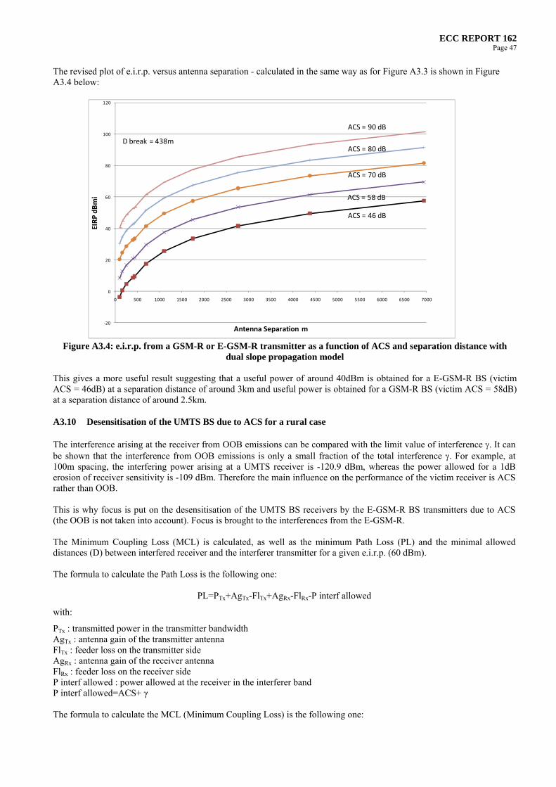
ECC REPORT 162 Page 47
The revised plot of e.i.r.p. versus antenna separation - calculated in the same way as for Figure A3.3 is shown in Figure A3.4 below:
‐20
0
20
40
60
80
100
120
0 500 1000 1500 2000 2500 3000 3500 4000 4500 5000 5500 6000 6500 7000
EIRP dBmi
Antenna Separation m
ACS = 58 dB
ACS = 46 dB
ACS = 70 dB
ACS = 80 dB
ACS = 90 dB
D break = 438m
Figure A3.4: e.i.r.p. from a GSM-R or E-GSM-R transmitter as a function of ACS and separation distance with
dual slope propagation model This gives a more useful result suggesting that a useful power of around 40dBm is obtained for a E-GSM-R BS (victim ACS = 46dB) at a separation distance of around 3km and useful power is obtained for a GSM-R BS (victim ACS = 58dB) at a separation distance of around 2.5km.
A3.10 Desensitisation of the UMTS BS due to ACS for a rural case
The interference arising at the receiver from OOB emissions can be compared with the limit value of interference . It can be shown that the interference from OOB emissions is only a small fraction of the total interference . For example, at 100m spacing, the interfering power arising at a UMTS receiver is -120.9 dBm, whereas the power allowed for a 1dB erosion of receiver sensitivity is -109 dBm. Therefore the main influence on the performance of the victim receiver is ACS rather than OOB. This is why focus is put on the desensitisation of the UMTS BS receivers by the E-GSM-R BS transmitters due to ACS (the OOB is not taken into account). Focus is brought to the interferences from the E-GSM-R. The Minimum Coupling Loss (MCL) is calculated, as well as the minimum Path Loss (PL) and the minimal allowed distances (D) between interfered receiver and the interferer transmitter for a given e.i.r.p. (60 dBm). The formula to calculate the Path Loss is the following one:
PL=PTx+AgTx-FlTx+AgRx-FlRx-P interf allowed
with:
PTx : transmitted power in the transmitter bandwidth AgTx : antenna gain of the transmitter antenna FlTx : feeder loss on the transmitter side AgRx : antenna gain of the receiver antenna FlRx : feeder loss on the receiver side P interf allowed : power allowed at the receiver in the interferer band P interf allowed=ACS+ γ The formula to calculate the MCL (Minimum Coupling Loss) is the following one:
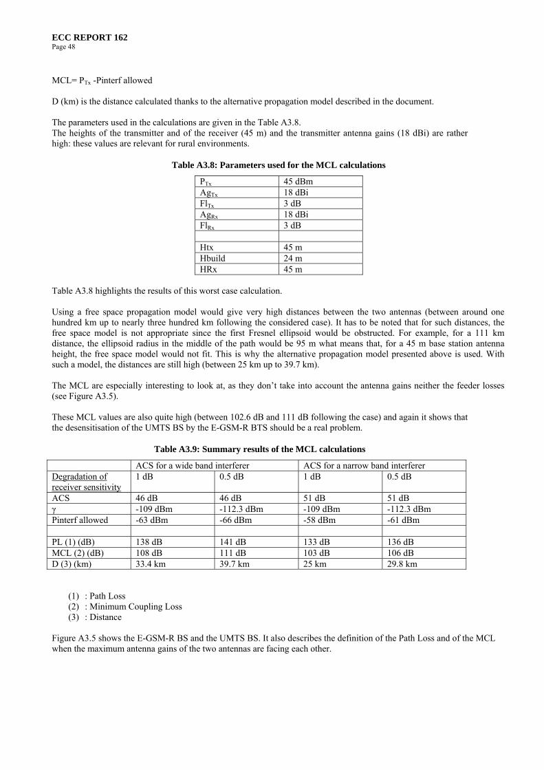
ECC REPORT 162 Page 48
MCL= PTx -Pinterf allowed D (km) is the distance calculated thanks to the alternative propagation model described in the document. The parameters used in the calculations are given in the Table A3.8. The heights of the transmitter and of the receiver (45 m) and the transmitter antenna gains (18 dBi) are rather high: these values are relevant for rural environments.
Table A3.8: Parameters used for the MCL calculations
PTx 45 dBm AgTx 18 dBi FlTx 3 dB AgRx 18 dBi FlRx 3 dB Htx 45 m Hbuild 24 m HRx 45 m
Table A3.8 highlights the results of this worst case calculation. Using a free space propagation model would give very high distances between the two antennas (between around one hundred km up to nearly three hundred km following the considered case). It has to be noted that for such distances, the free space model is not appropriate since the first Fresnel ellipsoid would be obstructed. For example, for a 111 km distance, the ellipsoid radius in the middle of the path would be 95 m what means that, for a 45 m base station antenna height, the free space model would not fit. This is why the alternative propagation model presented above is used. With such a model, the distances are still high (between 25 km up to 39.7 km). The MCL are especially interesting to look at, as they don’t take into account the antenna gains neither the feeder losses (see Figure A3.5). These MCL values are also quite high (between 102.6 dB and 111 dB following the case) and again it shows that the desensitisation of the UMTS BS by the E-GSM-R BTS should be a real problem.
Table A3.9: Summary results of the MCL calculations
ACS for a wide band interferer ACS for a narrow band interferer Degradation of receiver sensitivity
1 dB 0.5 dB 1 dB 0.5 dB
ACS 46 dB 46 dB 51 dB 51 dB γ -109 dBm -112.3 dBm -109 dBm -112.3 dBm Pinterf allowed -63 dBm -66 dBm -58 dBm -61 dBm PL (1) (dB) 138 dB 141 dB 133 dB 136 dB MCL (2) (dB) 108 dB 111 dB 103 dB 106 dB D (3) (km) 33.4 km 39.7 km 25 km 29.8 km
(1) : Path Loss (2) : Minimum Coupling Loss (3) : Distance
Figure A3.5 shows the E-GSM-R BS and the UMTS BS. It also describes the definition of the Path Loss and of the MCL when the maximum antenna gains of the two antennas are facing each other.

ECC REPORT 162 Page 49
Figure A3.5: Definitions of Path Loss and MCL (worst case: maximum of antenna gains facing each other)
With the same approach but applied to GSM-R DL band, the distance D is summarized in the table:
Table A3.10: Distances between GSM-R DL and UMTS900 UL
Degradation of receiver sensitivity η
0.5 1
D (km) 4.1 3.4 The distance is one of the possibilities to assure a minimum coupling loss. Other solutions could be envisaged like an adapted design of radio site (two antennas not face to face).
Path Loss
MCL
E-GSM-R BS UMTS BS
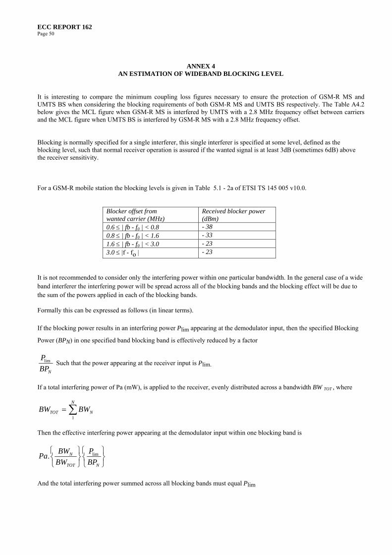
ECC REPORT 162 Page 50
ANNEX 4 AN ESTIMATION OF WIDEBAND BLOCKING LEVEL
It is interesting to compare the minimum coupling loss figures necessary to ensure the protection of GSM-R MS and UMTS BS when considering the blocking requirements of both GSM-R MS and UMTS BS respectively. The Table A4.2 below gives the MCL figure when GSM-R MS is interfered by UMTS with a 2.8 MHz frequency offset between carriers and the MCL figure when UMTS BS is interfered by GSM-R MS with a 2.8 MHz frequency offset. Blocking is normally specified for a single interferer, this single interferer is specified at some level, defined as the blocking level, such that normal receiver operation is assured if the wanted signal is at least 3dB (sometimes 6dB) above the receiver sensitivity.
For a GSM-R mobile station the blocking levels is given in Table 5.1 - 2a of ETSI TS 145 005 v10.0.
Blocker offset from wanted carrier (MHz)
Received blocker power (dBm)
0.6 | fb - f0 | < 0.8 - 38 0.8 | fb - f0 | < 1.6 - 33 1.6 | fb - f0 | < 3.0 - 23 3.0 |f - fo | - 23
It is not recommended to consider only the interfering power within one particular bandwidth. In the general case of a wide band interferer the interfering power will be spread across all of the blocking bands and the blocking effect will be due to the sum of the powers applied in each of the blocking bands.
Formally this can be expressed as follows (in linear terms).
If the blocking power results in an interfering power Plim appearing at the demodulator input, then the specified Blocking
Power (BPN) in one specified band blocking band is effectively reduced by a factor
lim
N
P
BP Such that the power appearing at the receiver input is Plim.
If a total interfering power of Pa (mW), is applied to the receiver, evenly distributed across a bandwidth BW TOT , where
1
N
TOT NBW BW
Then the effective interfering power appearing at the demodulator input within one blocking band is
lim. N
TOT N
BW PPa
BW BP
And the total interfering power summed across all blocking bands must equal Plim

ECC REPORT 162 Page 51
limlim
1
.N
N
TOT N
BW PPa P
BW BP
1
. 1N
N
TOT N
Pa BW
BW BP
So
1
TOT
NN
N
BWPa
BWBP
Where Pa is by definition the effective Blocking Level over the band BWTOT. Note this is not the same as average blocking
which would be defined as:
( * )N N
N
BP BW
BW
Note, this is method for averaging the receiver blocking; it makes no assumptions about particular mechanisms within the receiver. Further studies may be required to confirm the average blocking level by measurement.
This formulation is summarised in Table A 4.1 below for a GSM-R victim with centre frequency 924.8 MHz and an interferer at 927.6 ± (3.84/2) MHz or 925.68 to 929.52 MHz. There is no energy in the 1st blocking band 925.4-925.6 MHz so it can be removed from the calculation.
Table A4.1 The formulation of the average blocking power
2nd blocking band 3rd blocking band
blocking specification frequency offset MHz 0.8 1.6 1.6 >3
frequency range of interferer MHz 925.68 926.4 926.4 929.52
BWN MHz 0.72 3.12
blocking specification dBm -33 -23
BPN mW 5.01E-04 5.01E-03
BWN/BPN MHz/mW 1.44E+03 6.23E+02
Sum(BWN /BPN ) MHz/mW 2.06E+03
BWTOT MHz 3.84 Pa = 10*log10(BWTOT /Sum(BWN/BPN )) dBm -27.3
Table A4.1 The formulation of the average blocking power
Yielding an interfering power of -27.3 dBm in order that the blocking requirement shall be satisfied.
And the estimated Minimum Coupling Loss are given in Table A4.2

ECC REPORT 162 Page 52
Table A4.2 MCL to reach the blocking requirements of GSM-R MS and UMTS BS respectively
Interference relations
Additional conditions Simple calculations and explanations Needed MCL to avoid this interference relations
Case Blocking from UMTS BS to GSM-R MS
Blocking as defined by 3GPP specifications 45.005
Frequency offset of 2.8 MHz between UMTS and GSM-R carriers.
For a victim GSM-R mobile stations with centre frequency 924.8 MHz and an interfering UMTS BTS in range 927.6 +- 2.2 MHz. The blocking of GSM –R Mobile Receiver is –30.7 dBm for a 3 dB desensitization, as described in Table A2.3
Output power of UMTS BS is assumed to be +43 dBm/3.84 MHz.
+43 dBm - (- 27.3 dBm) = 70.3 dB.
70.3 dB
Case Blocking from UMTS BS to GSM-R MS
GSM-R Cab radio practical performance with blocking improvement filter
Filter is assumed to reject min 30 dB in rejection band and therefore practical performance of GSM-R cab radio to resist blocking is -5 dBm. Output power of UMTS BS is assumed to be +43 dBm.
+43 dBm - (-5 dBm) = 48 dB.
48 dB
Case Blocking from GSM-R MS to UMTS BS
For a I/N ratio of -10 dB, i.e. a desensitization of 0.6 dB
UMTS BS blocking requirement defined with a frequency offset of 2.8 MHz. 47 dBm corresponds to a 6 dB desensitization of UMTS BS.
+39 dBm- (-112.3 dBm + 51.4 dB) = 100 dB
100 dB

ECC REPORT 162 Page 53
ANNEX 5: LIST OF REFERENCES
[1] Directive 2009/136/EC of the European Parliament and of the Council of 25 November 2009 amending Directive 2002/22/EC on universal service and users’ rights relating to electronic communications networks and services, Directive 2002/58/EC concerning the processing of personal data and the protection of privacy in the electronic communications sector and Regulation (EC) No 2006/2004 on cooperation between national authorities responsible for the enforcement of consumer protection laws
[2] Directive 2009/140/EC of the European Parliament and of the Council of 25 November 2009 amending Directives 2002/21/EC on a common regulatory framework for electronic communications networks and services, 2002/19/EC on access to, and interconnection of, electronic communications networks and associated facilities, and 2002/20/EC on the authorisation of electronic communications networks and services
[3] DIRECTIVE 2009/114/EC OF THE EUROPEAN PARLIAMENT AND OF THE COUNCIL of 16 September 2009 amending Council Directive 87/372/EEC on the frequency bands to be reserved for the coordinated introduction of public pan-European cellular digital land-based mobile communications in the Community
[4] Commission Decision 2009/766/EC of 16 October 2009 on the harmonisation of the 900 MHz and 1 800 MHz frequency bands for terrestrial systems capable of providing pan-European electronic communications services in the Community
[5] Council Directive 96/48/EC of 23 July 1996 on the interoperability of the trans-European high-speed rail system
[6] Directive 2001/16/EC of the European Parliament and of the Council of 19 March 2001 on the interoperability of the trans-European conventional rail system
[7] ECC Decision of 1 December 2006 on the designation of the bands 880-915 MHz, 925-960 MHz, 1710-1785 MHz and 1805-1880 MHz for terrestrial IMT-2000/UMTS systems (ECC/DEC/(06)13)
[8] ECC Decision of 19 March 2004 on the availability of frequency bands for the introduction of Wide Band Digital Land Mobile PMR/PAMR in the 400 MHz and 800/900 MHz bands amended 26 June 2009 (Amended ECC/DEC/(04)06, Amended the Annex to the Decision 27 June 2008)
[9] ECC Decision of 5 July 2002 on the designation and availability of frequency bands for railway purposes in the 876-880 MHz and 921-925 MHz bands amended 26 June 2009 (Amended ECC/DEC/(02)05)
[10] ERC Decision of 21 March 1997 on the extended frequency bands to be used for the GSM Digital Pan-European Communication System (ERC/DEC/(97)02)
[11] ERC Decision of 24 October 1994 on the frequency bands to be designated for the coordinated introduction of the GSM digital pan-European communications system (ERC/DEC/(94)01)
[12] ECC Report 096, Compatibility between UMTS 900/1800 and systems operating in adjacent bands, Krakow, March 2007
[13] ECC Report 127, The impact of receiver standards on spectrum management, Cordoba, October 2008
[14] ETSI TS 145 005 V8.5.0 (2009-06), Technical Specification Digital cellular telecommunications system (Phase 2+); Radio transmission and reception (3GPP TS 45.005)
[15] TS 125.101 Universal Mobile Telecommunications System (UMTS);User Equipment (UE) radio transmission and reception (FDD) (3GPP TS 25.101 version 9.2.0 Release 9 (2009-12))
[16] TS 136.101 LTE; Evolved Universal Terrestrial Radio Access (E-UTRA); User Equipment (UE) radio transmission and reception(3GPP TS 36.101 version 9.2.0 Release 9 (2009-12))
[17] Report of the 54th WG SE MEETING, Doc. 124SE(09) Annex 26
[18] ECC Report 146, on compatibility between GSM MCBTS and other services (TRR, RSBN/PRMG, HC-SDMA, GSM-R, DME, MIDS, DECT) operating in the 900 and 1800 MHz frequency bands.
[19] CEPT Report 41 Compatibility between LTE and WiMAX operating within the bands 880-915 MHz / 925-960 MHz and 1710-1785 MHz / 1805-1880 MHz (900/1800 MHz bands) and systems operating in adjacent bands
[20] ERC Report 56, DSI PHASE II (900 MHz ISSUES) GSM-UIC, Saariselkä, January 1998
[21] ETSI TS 125 104 V8.8.0 (2009-10) Technical Specification Universal Mobile Telecommunications System (UMTS); Base Station (BS) radio transmission and reception (FDD) (3GPP TS 25.104 version 8.8.0 Release 8)
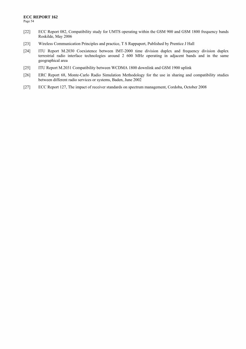
ECC REPORT 162 Page 54
[22] ECC Report 082, Compatibility study for UMTS operating within the GSM 900 and GSM 1800 frequency bands Roskilde, May 2006
[23] Wireless Communication Principles and practice, T S Rappaport, Published by Prentice J Hall
[24] ITU Report M.2030 Coexistence between IMT-2000 time division duplex and frequency division duplex terrestrial radio interface technologies around 2 600 MHz operating in adjacent bands and in the same geographical area
[25] ITU Report M.2031 Compatibility between WCDMA 1800 downlink and GSM 1900 uplink
[26] ERC Report 68, Monte-Carlo Radio Simulation Methodology for the use in sharing and compatibility studies between different radio services or systems, Baden, June 2002
[27] ECC Report 127, The impact of receiver standards on spectrum management, Cordoba, October 2008