ece 422 system operations planning 8 voltage...
TRANSCRIPT

1
Spring 2015Instructor: Kai Sun
ECE 422 Power System Operations & Planning
8 ‐ Voltage Stability

2
Voltage Stability
• Voltage stability is concerned with the ability of a power system to maintain acceptable voltages at all buses in the system under normal conditions and after being subjected to a disturbance.
• A system enters a state of voltage instability (or voltage collapse) when a disturbance, e.g. increase in load demand, or change in system condition causes a progressive and uncontrollable decline in voltage
• The main factor causing instability is the inability of the power system to meet the demand for reactive power
• Voltage stability problems normally occur in heavily stressed systems.
• References:– Chapter 14 of Kundur’s book– “Survey of the voltage collapse phenomenon”, NERC Report, Aug. 1991– EPRI Tutorial’s Chapter 6– Carson W. Taylor, “Power System Voltage Stability” McGraw Hil, 1994– “Voltage Stability Assessment: Concepts, Practices and Tools”, IEEE whitepaper, Aug. 2002

3
Voltage Stability vs. Rotor Angle stability• Voltage stability is basically load stability, and rotor angle stability is basically generator stability
• For rotor angle stability, we are often concerned with integrating remote power plants to a large system over long transmission lines.
• Voltage stability is concerned with load areas and load characteristics. In a large interconnected system, voltage collapse of a load area is possible without loss of synchronism of any generators.
• Transient voltage stability is usually closely associated with transient rotor angle stability. If voltage collapse at a point in a transmission system remote from loads, it is, in nature, an angle instability problem.
Typical region with voltage stability concerns

4
A simple radial system
where
ZLD decreases (assume constant ZLN)
S
LN LD
EIZ Z
2 2( cos cos ) ( sin sin )S
LN LD LN LD
EIZ Z Z Z
1 S
LN
EIZF
2
1 2 cos( )LD LD
LN LN
Z ZFZ Z
• How does VR change as PR increases?
R LDV Z I cosR RP V I
1 LDR LD S
LN
ZV Z I EZF
2
cos cosSLDR R
LN
EZP V IF Z

5
• Voltage stability depends on the load characteristics– Under normal conditions, to increase power PR, a load control strategy usually decreases ZLD
– However, when ZLD<ZLN (heavy load conditions), a decrease in ZLDreduces PR, so a control on power by varying load may be unstable
– For example, if the load is supplied by transformers with automatic ULTC, the tap‐changer action will try to raise the load voltage (absorbing more Mvar from the primary side), which has the effect of reducing the effective ZLD as seen from the system and in turn lowers VR further to lead to a progressive reduction of voltage
ZLD decreases (assume constant ZLN)

6
Constant P
PR=P
Constant Z
PR=aVR2
• Voltage collapse happens when the system passes the critical point (also called the “nose point” or “knee point”).
ZLD decreases (assume constant ZLN)
P‐V Curve

7
Normalized P‐V curves ( varies)• Normally, only the operating points above the critical points represent satisfactory operating conditions
A sudden reduction in (increase in QR)

8
IEEE 39‐bus test system
PAera 1 - V530Uniformly scale up the area load with
constant

9
Influence of Generation Characteristics
• Generator AVRs provide the primary source of voltage support to maintain constant terminal voltages under normal conditions.
• During conditions of low/high voltages, the Q output of a generator may reach its limit. Consequently, the terminal voltage is not longer maintained constant
• Then, with constant field current, the point of constant voltage is now Eq behind the synchronous reactance XSXd. That increases the network reactance significantly to further aggravating the voltage collapse condition
• It is important to maintain the voltage control capability of generators
• The degree of voltage stability cannot be judged based only on how close the bus voltage is to the normal voltage level
Voltage collapse happens when the Q limit is reached

10
112
3
112
33
1GW generation tripped by SPS
4
44
Faulty zone 3 relay
5
5
6 8
6 7
7
8
Loss of key hydro units
Tripped by Zone 3 relay
9
9
10
Tree contact
and relay
mis-opt.
Example of Voltage Collapse -
July 2nd, 1996 Western Cascading Event

11
•On July 3rd, 1996, i.e. the following day, – A similar chain of events happened to cause voltages in Boise area to decline.
– Different from the previous day, Idaho Power Company system operators noted the declining voltages and immediately took the only option available: shedding of Boise area load
– Then, the system returned to normal within 1 hour
•Lessons learned:– The July 2nd and 3rd events in Boise, Idaho area emphasize the need for effective and sufficient, rapidly responsive dynamic Mvar reserve.
– The July 3rd events illustrate the importance of system operators’ situational awareness and rapid responses.

12
Prevention of Voltage Instability• Application of var compensating devices
– Ensure adequate stability margin (in MW or Mvar)– Selection of sizes, ratings and locations of the devices (especially for dynamic reactive reserves, e.g. synchronous condensers and SVCs)
– Design criteria based on maximum allowable post‐contingency voltage drop are often NOT satisfactory from voltage stability viewpoint
– Important to recognize voltage control areas and weak boundaries.• Control of transformer tap changers
– Can be controlled either locally or centrally– Where tap changing is detrimental, tap changing should be blocked when the source‐side voltage sags and unblocked when voltage recovers
• Control of network voltage and generator reactive output– Improvement on AVRs– Add secondary coordinated outer‐loop voltage control (e.g. the hierarchical, automatic two/three‐layer voltage control)
13
Prevention of Voltage Instability (cont’d)
• Coordination of protections/controls– Adequate coordination ensured based on dynamic simulation studies– Tripping of equipment to protect from overloaded conditions should be the last resort. The overloaded conditions could be relieved by adequate control measures before isolating the equipment.
•Under‐voltage load shedding (UVLS)– For unplanned or extreme situations; analogous to UFLS– Provide a low‐cost means of preventing widespread system collapse– Particularly attractive if conditions leading to voltage instability are of low probability but consequences are high
– Characteristics and locations of the loads to be shed are more important for voltage problems than for frequency problems
– Should be designed to distinguish between faults, transient voltage dips, and low voltage conditions leading to voltage collapse
14
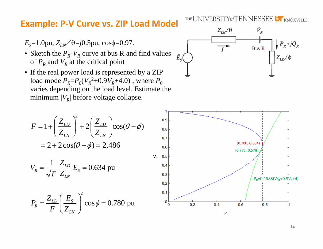
ES=1.0pu, ZLN=j0.5pu, cos=0.97. • Sketch the PR-VR curve at bus R and find values
of PR and VR at the critical point• If the real power load is represented by a ZIP
load mode PR=P0(VR2+0.9VR+4.0) , where P0
varies depending on the load level. Estimate the minimum |VR| before voltage collapse.
2
1 2 cos( )
2 2cos( ) 2.486
LD LD
LN LN
Z ZFZ Z
1 0.634 puLDR S
LN
ZV EZF
2
cos 0.780 puSLDR
LN
EZPF Z
Example: P‐V Curve vs. ZIP Load Model