ece 445 fall 2012 senior design project proposal
TRANSCRIPT

ECE 445
Fall 2012
Senior Design Project Proposal
Bluetooth Stereo Network
Team 7
Jeff Wheeler
Rishi Ratan
Jerry Sun
Prof. Andrew Carl Singer
TA: Justine Fortier

ECE 445: Senior Design Project Proposal – Team 7 (Fall 2012) 2 | P a g e
Table of Contents 1.0 Introduction ........................................................................................................... 3
1.1 Project Overview ................................................................................................ 3
1.2 Objectives .......................................................................................................... 3
1.2.1 Goals ........................................................................................................... 3
1.2.2 Benefits ........................................................................................................ 3
1.2.3 Features ...................................................................................................... 3
2.0 Design Overview ................................................................................................... 4
2.1 Block Diagrams .................................................................................................. 4
2.2 Block Descriptions .............................................................................................. 5
2.2.1 Hub .............................................................................................................. 5
2.2.2 Speaker Adapter .......................................................................................... 7
3.0 Requirements and Verification .............................................................................. 9
3.1 Testing Procedure .............................................................................................. 9
3.2 Tolerance Analysis ........................................................................................... 11
4.0 Cost and Schedule .............................................................................................. 12
4.1 Cost Analysis ................................................................................................... 12
4.1.1 Labor ......................................................................................................... 12
4.1.2 Parts .......................................................................................................... 12
4.1.3 Grand Total ................................................................................................ 12
4.2 Schedule .......................................................................................................... 13

ECE 445: Senior Design Project Proposal – Team 7 (Fall 2012) 3 | P a g e
1.0 Introduction
1.1 Project Overview
The goal of this project is to design and develop a Bluetooth-powered stereo network that accepts audio data from User-Equipment (UE) and seamlessly transfers this data wirelessly to speakers closest to the UE location. Numerous Bluetooth-powered speakers currently exist in the consumer market, however none of them provide location specific audio playback, have limited range, and moderate audio quality. The product we plan to develop over the course of this semester is unavailable in the wireless audio industry and would greatly streamline/improve the wireless audio playback experience for consumers.
1.2 Objectives
1.2.1 Goals
We intend to develop a stereo network in which a user can play music from their phone or other device over Bluetooth (BT) to a centralized hub, which will then forward the audio data to the speaker network, choosing the appropriate speaker to play depending on its proximity to the UE. This network will be composed of speaker adapters like those currently available in the market, but modified to observe how strongly it “sees” the user equipment (e.g. by measuring attenuation on the BT signal from the streaming device) and relaying this information to the hub. We seek a system in which the UE only need pair with the central hub and does not need to pair and subsequently un-pair with each speaker as it moves between rooms. The UE will pair with this hub (and not the individual speakers), which will then forward the audio data to the appropriate “speaker adapter” based on where it thinks the user is.
1.2.2 Benefits
User-friendly with superior form-factor. No additional software/hardware needed for phone or other UEs. Seamless pairing with speakers without a need since the hub centrally
connects all the speakers. Compatible with all existing speakers on the market that support 3.5mm
audio jack.
1.2.3 Features
Compatible with any Bluetooth enabled audio device. CD quality uncompressed audio. Audio range of upto 30 feet from hub to speaker and from speaker to UE. Dedicated audio streaming via TI PurePath wireless. Support for streaming on up to 4 devices. Microcontroller-Unit (MCU) for hub and speaker management.

ECE 445: Senior Design Project Proposal – Team 7 (Fall 2012) 4 | P a g e
2.0 Design Overview
2.1 Block Diagrams
Fig 1: Overall System Setup Block Diagram
Fig 2: Hub Setup Block Diagram
Fig 2: Hub Setup Block Diagram

ECE 445: Senior Design Project Proposal – Team 7 (Fall 2012) 5 | P a g e
2.2 Block Descriptions
2.2.1 Hub
Microcontroller Unit
The microcontroller unit (MCU) manages the operation of the hub. The hub is responsible for initializing the Bluetooth unit at boot to broadcast for pairing, and to manage the flow of pairing with the UE when the user attempts to pair. MCU is also responsible for choosing the appropriate speaker to forward audio data to, using the signal strength data it receives from the speaker (via the PurePath unit).
Bluetooth Unit
The Bluetooth (BT) Unit consists of the Bluetooth (BT) IC, an antenna, and a crystal oscillator providing the “slow clock” for the Bluetooth IC. In the hub, the Bluetooth chip will be used to pair with the UE, and A2DP (Advanced Audio Distribution Profile, a Bluetooth communication profile used to transmit stereo data) will be used to download the audio stream from the UE. The Bluetooth IC will speak I2S (Inter-IC Sound) directly to the PurePath unit, which will re-transmit the audio data to the speaker adapters. Additionally, the BT IC will speak UART to the microcontroller, which will be used to send the BT IC commands to enter pairing mode and set its visibility, as well as to enable the I2S output pins.
Fig 3: Speaker Adapter Setup Block Diagram

ECE 445: Senior Design Project Proposal – Team 7 (Fall 2012) 6 | P a g e
PurePath Unit
The PurePath (PP) Unit consists of the PurePath IC and a crystal oscillator. The PP IC in the hub is responsible for encoding and decoding the PP radio signals. The MCU will use I2C, speaking to the PP IC, to control which speaker adapter the device sends to. Finally, the BT IC will send audio data for broadcast to speaker adapters to the PurePath IC in the form of I2S. The PP IC also receives the signal strength to the UE from each speaker adapter, in the form of a returning audio stream. This data is provided to the MCU as an I2S audio stream and will aid in determining the appropriate speaker to play audio data to. In order to program IC we directly use a proprietary PP IC programmer and its associated software developed by Texas Instruments (TI), but certain broadcast settings are specified at runtime by the MCU, to control which speaker adapters play the audio.
PurePath RF Front-End
The PurePath RF Frontend includes an RF frontend amplifier IC and antenna. We hope to use the TI CC2590 chip as an integral part of our RF Front-End. The chip is optimal for low-power and low voltage wireless applications at 2.4GHz and has a seamless integration with the PP IC.
A key feature about incorporating this chip into our design is that it increases the link-budget as it contains an in-built power amplifier (PA) to enhance the output power and a Low-Noise Amplifier (LNA) with high gain and low-noise to enhance our receiver sensitivity.
We will also use an integrated RF transceiver chip in combination
with the CC2590 chip to provide hardware support for packet
handling, data buffering, burst transmissions, data encryption, data
authentication, clear channel assessment, link quality indication and
packet timing information. The key advantage of using this chip is that
it reduces the load on the PP IC by directly interfacing with the MCU.
Power Supply
The power supply will provide a regulated voltage source to all of our
ICs, most of which require a power rail at about 3.3V. For the hub, this
rail will be regulated from a static 5V USB micro-B source.

ECE 445: Senior Design Project Proposal – Team 7 (Fall 2012) 7 | P a g e
2.2.2 Speaker Adapter
Microcontroller Unit
The MCU manages the operation of the speaker. To do this, it needs to coordinate the Bluetooth Unit and the PurePath Unit, in addition to performing some initialization of ICs in the audio frontend (e.g. to specify the DSP settings via I2C). Most critically after initializing devices at boot, the MCU is responsible for encoding the signal strength data (as seen to the UE) available from the Bluetooth IC, received via UART, as I2S data to send to the audio input in the PurePath Unit. Furthermore, MCU needs to initialize the PurePath Unit such that it sends its audio input back to the master.
Bluetooth Unit
The Bluetooth Unit consists of the BT IC, an antenna, and a crystal oscillator providing the “slow clock” for the BT IC. The speaker BT IC never pairs with anything: it is used exclusively to discover the signal strength of the UE, and never transmits any data. The microcontroller requests the signal strength data via UART.
PurePath Unit
The PurePath Unit consists of the PurePath IC and a crystal oscillator. In the speaker adapter the PP IC is responsible for encoding and decoding the PurePath radio signals. The microcontroller will send the BT signal strength data in the form of I2S, which will be broadcast back to the hub, while the received audio stream will be pushed to the audio frontend, also as I2S. The PurePath IC is programmed directly using a PurePath IC programmer, but specific parameters will be configured at runtime by the microcontroller.
PurePath RF Front-End
The functionality of the PurePath RF Front-End will be similar to that
used on the hub, so reference the description provided in the
respective section.
Power Supply
The power supply will provide a regulated voltage source to all of our
ICs, most of which require a power rail at about 3.3V. For the speaker,
this will be supplied from a lithium-ion battery which will be charged
via a USB micro-B port.

ECE 445: Senior Design Project Proposal – Team 7 (Fall 2012) 8 | P a g e
Audio Front-End
The audio frontend of the speaker will include an audio codec that includes a DAC, as well as a high-power audio amplifier connected to a 3.5mm audio jack that a line-out wire can connect to.
This unit serves to connect the PurePath unit, which outputs audio as I2S, to the system’s analog output which connects to physical stereo speakers.

ECE 445: Senior Design Project Proposal – Team 7 (Fall 2012) 9 | P a g e
3.0 Requirements and Verification
3.1 Testing Procedure
Block Requirement Verification
Hub
Microcontroller Unit
1. Accepts signal strength data encoded as I2S and picks a speaker based on that by sending SPI control packets addressed to the PurePath IC that specify the speaker to play to.
1. Drive test values on the I2C/I2S lines via the NI-DAQ. The data will simulate the audio stream returning from the PurePath IC with the signal strength data. The stream will include a speaker ID followed by the signal strength data. While sending stream strength data, cycle through letting each speaker be associated with the strongest signal strength values. The microcontroller must broadcast a correctly-formed SPI packet with an instruction to switch to the speaker with the strongest strength.
Bluetooth Unit 1. Device must be visible over Bluetooth to UE by broadcasting its device name and UE must be able to connect to the Bluetooth module
2. UE must be able to stream audio to the BT unit using A2DP which is output from the unit as I2S
1. Develop test program that indicates, via UART, for the unit to be visible with a given name. Use a BT device (any phone) to pair with the Bluetooth unit
2. Develop test program that indicates, via UART, for the unit to accept A2DP data. Then, connect to the unit through UE (any phone) and stream audio. Listen to the I2S output audio stream with a NI-DAQ and verify signal authenticity.
PurePath Unit 1. Convert provided I2S signal into PurePath proprietary signaling around 2.4GHz for broadcast over the air.
1. Program PurePath unit to always broadcast received I2S audio data. Generate I2S test signal using NI-DAQ and feed it into the audio input line of the PurePath unit. Measure RF output signal from the unit on a VSA by verifying the signal resides around 2.4GHz with typical output power level of 3.5dBm.

ECE 445: Senior Design Project Proposal – Team 7 (Fall 2012) 10 | P a g e
PP RF Front-End 1. Transmits the 2.4GHz PurePath signals from the PurePath unit over the air (OTA) at minimum 10dBm output power.
2. Must achieve a noise figure of 4±1dB on receive with a 10dB gain.
1. Drive test data in I2S using NI-DAQ into PurePath IC, generating 2.4GHz input signal. Measure RF output signal strength on a VSA by verifying new signals in the 2.4GHz spectrum.
2. Characterize the S-parameters of the device using a PNA.
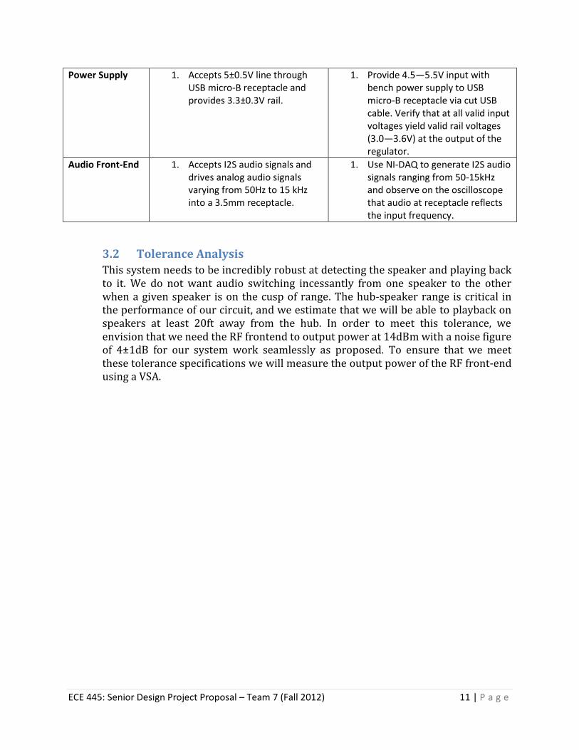
Power Supply 1. Accepts 5±0.5V line through USB micro-B receptacle and provides 3.3±0.3V rail.
1. Provide 4.5—5.5V input with bench power supply to USB micro-B receptacle via cut USB cable. Verify that at all valid input voltages yield valid rail voltages (3.0—3.6V) at the output of the regulator.
Speaker Adapter
Microcontroller Unit
1. Must request signal strength data from Bluetooth unit over UART and publish that data in the form of I2S packets (I2C plus the Wire Select Line, which will be held low).
1. Power the Bluetooth unit and connect the UART lines to the microcontroller. Program microcontroller to request list of visible Bluetooth devices via UART. Observe I2S output line (via NI-DAQ) reflects the proximity of the UE to the antenna.
Bluetooth Unit 1. Silently listens to Bluetooth signals but never actively broadcasts.
2. Able to list available BT devices within 20ft and their signal strength values
1. Enable unit execution and measure RF output signal from the unit on a VSA to verify that no new signals reside around 2.4GHz.
2. Program microcontroller to request list of visible devices over UART, and broadcast this I2C. Listen to the I2C bus via NI-DAQ and verify that UE shows up in I2C list when Bluetooth is enabled within a 20ft radius. Verify that the signal strength value adjusts according to the proximity of the UE to the antenna.
PurePath Unit 1. Same requirements as in unit in the hub.
1. Same verification steps as in the unit in the hub.
PP RF Front-End
1. Same requirements as in unit in the hub.
1. Same verification steps as in the unit in the hub.
ECE 445: Senior Design Project Proposal – Team 7 (Fall 2012) 11 | P a g e
Power Supply 1. Accepts 5±0.5V line through USB micro-B receptacle and provides 3.3±0.3V rail.
1. Provide 4.5—5.5V input with bench power supply to USB micro-B receptacle via cut USB cable. Verify that at all valid input voltages yield valid rail voltages (3.0—3.6V) at the output of the regulator.
Audio Front-End 1. Accepts I2S audio signals and drives analog audio signals varying from 50Hz to 15 kHz into a 3.5mm receptacle.
1. Use NI-DAQ to generate I2S audio signals ranging from 50-15kHz and observe on the oscilloscope that audio at receptacle reflects the input frequency.
3.2 Tolerance Analysis
This system needs to be incredibly robust at detecting the speaker and playing back to it. We do not want audio switching incessantly from one speaker to the other when a given speaker is on the cusp of range. The hub-speaker range is critical in the performance of our circuit, and we estimate that we will be able to playback on speakers at least 20ft away from the hub. In order to meet this tolerance, we envision that we need the RF frontend to output power at 14dBm with a noise figure of 4±1dB for our system work seamlessly as proposed. To ensure that we meet these tolerance specifications we will measure the output power of the RF front-end using a VSA.
ECE 445: Senior Design Project Proposal – Team 7 (Fall 2012) 12 | P a g e
4.0 Cost and Schedule
4.1 Cost Analysis
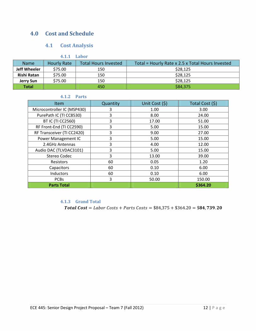
4.1.1 Labor
Name Hourly Rate Total Hours Invested Total = Hourly Rate x 2.5 x Total Hours Invested Jeff Wheeler $75.00 150 $28,125
Rishi Ratan $75.00 150 $28,125
Jerry Sun $75.00 150 $28,125
Total 450 $84,375
4.1.2 Parts
Item Quantity Unit Cost ($) Total Cost ($) Microcontroller IC (MSP430) 3 1.00 3.00
PurePath IC (TI CC8530) 3 8.00 24.00
BT IC (TI CC2560) 3 17.00 51.00
RF Front-End (TI CC2590) 3 5.00 15.00
RF Transceiver (TI CC2420) 3 9.00 27.00
Power Management IC 3 5.00 15.00
2.4GHz Antennas 3 4.00 12.00
Audio DAC (TLVDAC3101) 3 5.00 15.00
Stereo Codec 3 13.00 39.00
Resistors 60 0.05 1.20
Capacitors 60 0.10 6.00
Inductors 60 0.10 6.00
PCBs 3 50.00 150.00
Parts Total $364.20
4.1.3 Grand Total

ECE 445: Senior Design Project Proposal – Team 7 (Fall 2012) 13 | P a g e
4.2 Schedule
Week Jeff Rishi Jerry 9/17 Proposal:
Finalize system block diagrams and Requirements/Verification for each block.
Proposal: Finalize system level block descriptions, introduction/features and defined RF Requirements/Verifications. Ordered initial parts.
Proposal: Developed initial proposal structure, supervised overall block descriptions, tolerance analysis and cost.
9/24 Design schematic for MCU and its interface to PurePath IC. Analyze I2C/I2S signals generated by MCU using NI-DAQ, working towards software testing for Design Review.
Design and simulate the power supply circuit. Conduct simulations in Spice and complete the circuit design. Characterize the RF chips used in the PurePath RF Front-End circuit to verify their compatibility as per the design requirements highlighted in proposal.
Evaluate Bluetooth chips and verify their programmability. Test I2C integration into the analog audio front-end. Research UART interface to Bluetooth IC.
10/1 Design Reviews and create MCU PCB footprints, then begin layout, optimizing for board size.
Design Review and learn about PCB layout and make footprints for RF and Power ICs.
Design Review and learn about PCB layout and make footprints for BT and PP ICs.
10/8 Layout PCB and verify that it matches schematic. Start to write MCU programs for each device, and program the PurePath ICs.
Prototype power-supply design on breadboard and test integration of RF front end circuit for PurePath ICs.
Prototype analog audio front-end design on breadboard and test integration of BT ICs and experiment with UART.
10/15 Adjust PCB layout according to discoveries from debugging breadboard circuits, and continue to write MCU programs.
Order new parts as needed (including full BOM for completed boards). Debug breadboard circuits from previous week. Consider ordering first-round PCBs if debugging is going well.
Continue debugging UART interface to BT ICs on hub and speaker adapters, and learn SPI interface for PurePath ICs.
10/22 Complete Individual Reports. Complete Individual Reports. Complete Individual Reports.
10/29 Order next set of PCBs, updated according to initial testing. Integrate UART and SPI interfaces into MCUs.
Validating design choices for PCB RF circuits and verifying RF front-end behavior. Analyze battery behavior with rechargeable circuit.
Assemble PCBs, mounting almost exclusively QFN ICs. Finalize UART and SPI interface with BT ICs, PP ICs, and MCU.
11/5 Prepare for Mock-up Demos Prepare for Mock-up Demos Prepare for Mock-up Demos
11/12 Prepare Mock-up Presentations and finalize final design.
Prepare Mock-up Presentations and finalize final design.
Prepare Mock-up Presentations and finalize final design.
11/19 Thanksgiving Break Thanksgiving Break Thanksgiving Break
11/26 Consolidate work and start writing the final project report.
Consolidate work and start writing the final project report.
Consolidate work and start writing the final project report.
12/3 Project Demo Project Demo Project Demo
12/10 Final Design Presentations! Final Design Presentations and Graduation!
Final Design Presentations!