ece 545 lecture 6 behavioral modeling o sequential...
TRANSCRIPT
George Mason University
Behavioral Modeling of Sequential-Circuit Building Blocks
ECE 545 Lecture 6
2
Required reading
• P. Chu, RTL Hardware Design using VHDL
Chapter 5.1, VHDL Process
Chapter 8, Sequential Circuit Design: Principle
3 ECE 448 – FPGA and ASIC Design with VHDL
Behavioral Design Style: Registers & Counters
4
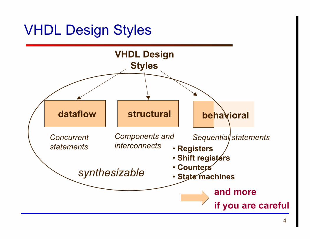
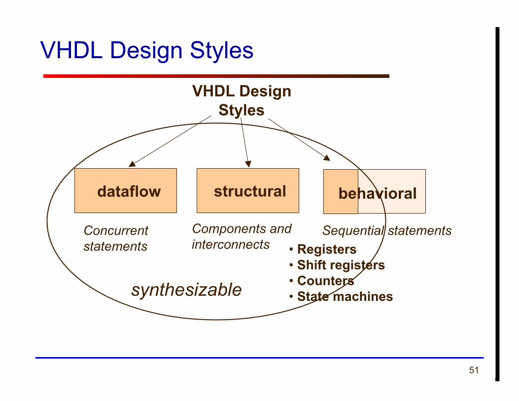
VHDL Design Styles
Components and interconnects
structural
VHDL Design Styles
dataflow
Concurrent statements
behavioral
• Registers • Shift registers • Counters • State machines
Sequential statements
and more if you are careful
synthesizable
5
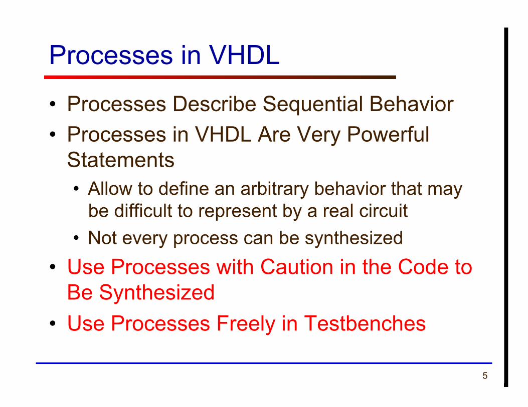
Processes in VHDL
• Processes Describe Sequential Behavior • Processes in VHDL Are Very Powerful
Statements • Allow to define an arbitrary behavior that may
be difficult to represent by a real circuit • Not every process can be synthesized
• Use Processes with Caution in the Code to Be Synthesized
• Use Processes Freely in Testbenches
6
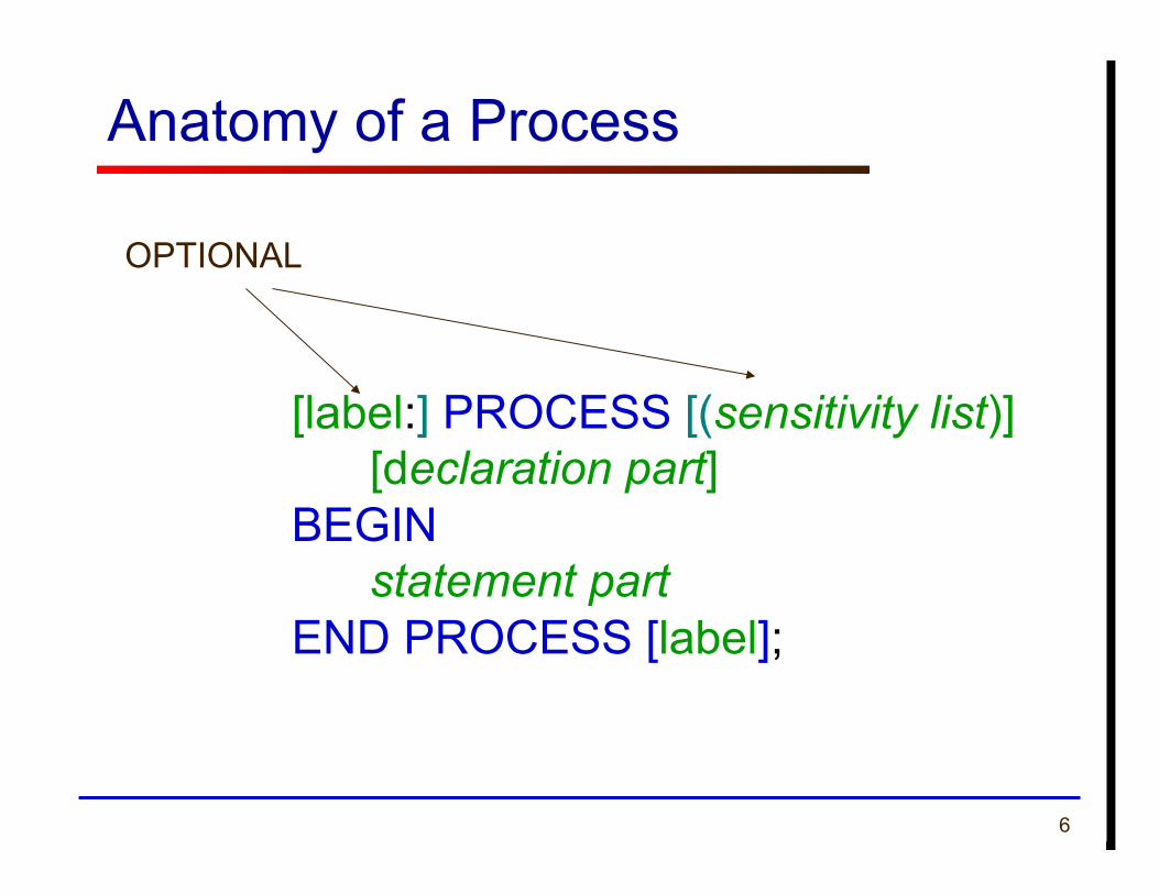
Anatomy of a Process
[label:] PROCESS [(sensitivity list)] [declaration part] BEGIN statement part END PROCESS [label];
OPTIONAL
7
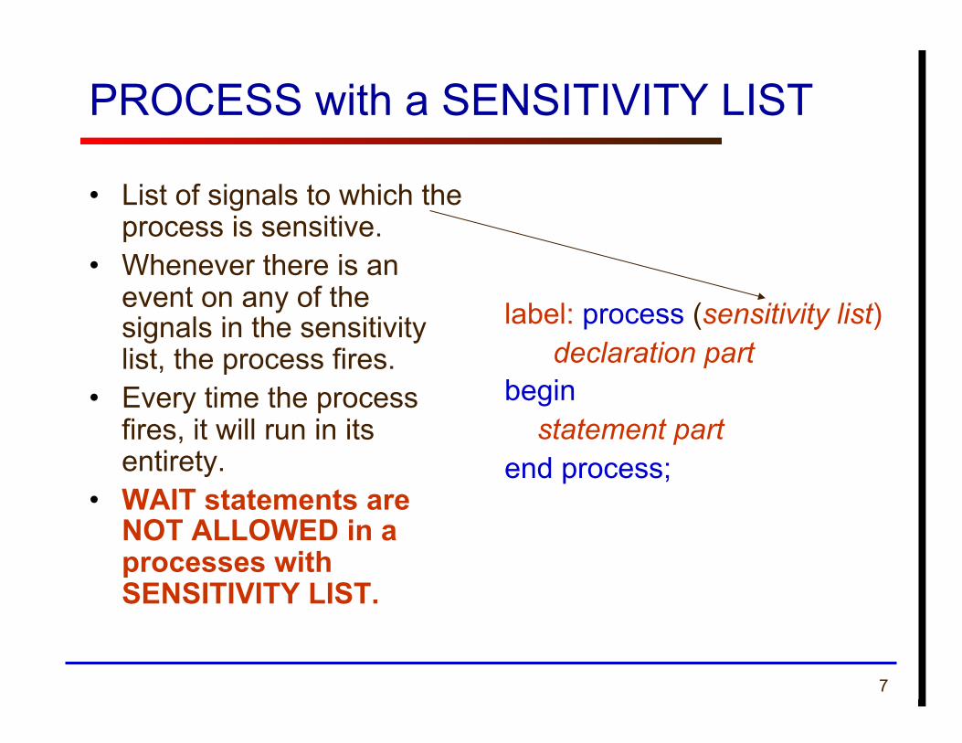
PROCESS with a SENSITIVITY LIST
• List of signals to which the process is sensitive.
• Whenever there is an event on any of the signals in the sensitivity list, the process fires.
• Every time the process fires, it will run in its entirety.
• WAIT statements are NOT ALLOWED in a processes with SENSITIVITY LIST.
label: process (sensitivity list) declaration part begin
statement part end process;
8
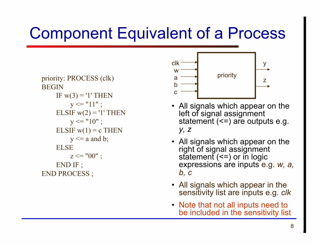
Component Equivalent of a Process
• All signals which appear on the left of signal assignment statement (<=) are outputs e.g. y, z
• All signals which appear on the right of signal assignment statement (<=) or in logic expressions are inputs e.g. w, a, b, c
• All signals which appear in the sensitivity list are inputs e.g. clk
• Note that not all inputs need to be included in the sensitivity list
priority: PROCESS (clk) BEGIN IF w(3) = '1' THEN y <= "11" ; ELSIF w(2) = '1' THEN y <= "10" ; ELSIF w(1) = c THEN y <= a and b; ELSE z <= "00" ; END IF ; END PROCESS ;
wa
y
z priority
b c
clk
9 ECE 448 – FPGA and ASIC Design with VHDL
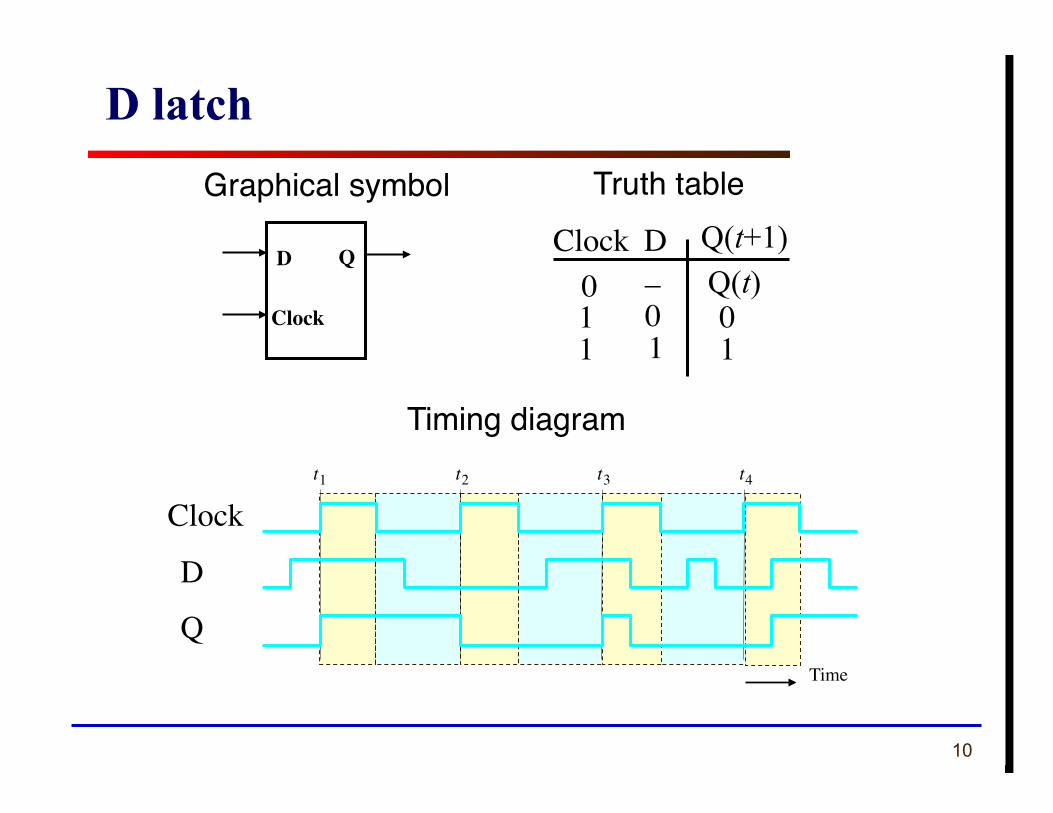
Registers
10
Clock D 0 1 1
– 0 1
0 1
Truth table Graphical symbol
t 1 t 2 t 3 t 4
Time
Clock
D
Q
Timing diagram
Q(t+1) Q(t)
D latch
D Q
Clock
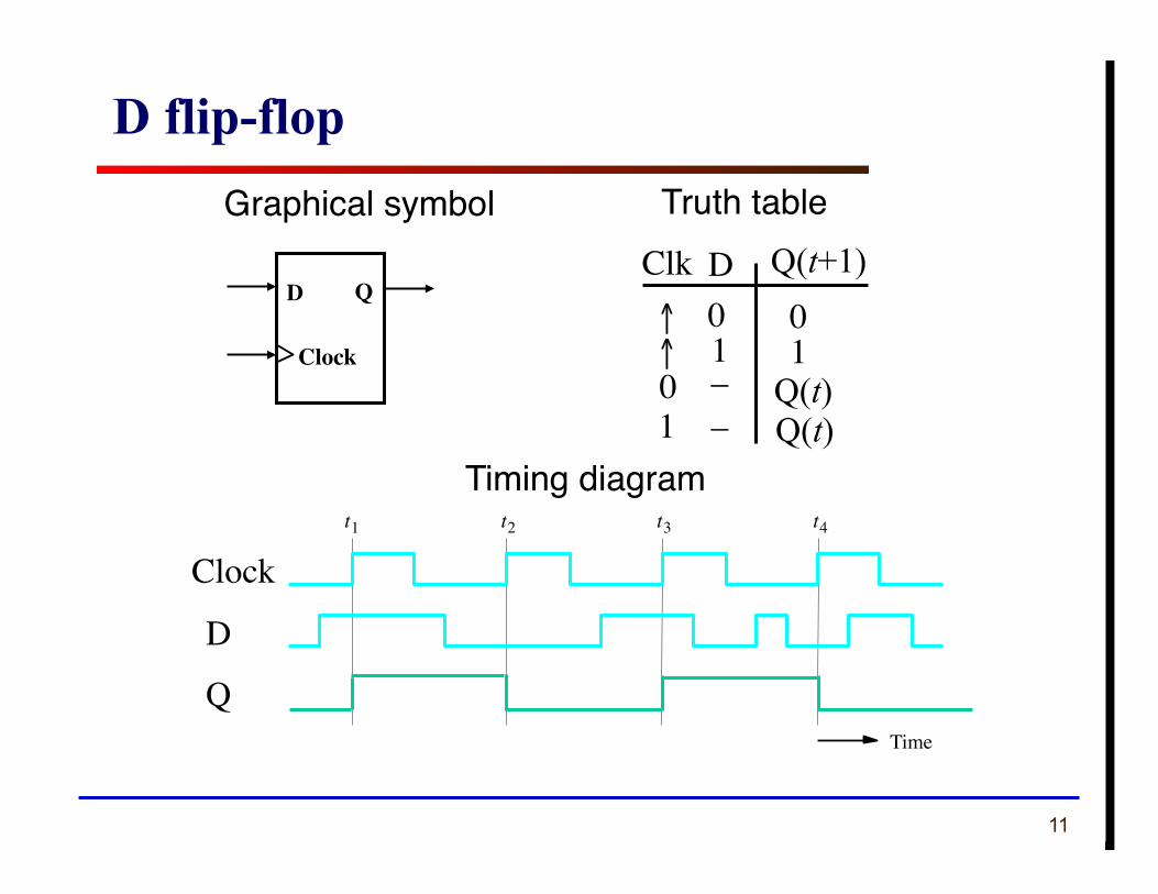
11
Clk D ↑ ↑
0 1
0 1
Truth table
t 1 t 2 t 3 t 4
Time
Clock
D
Q
Timing diagram
Q(t+1)
Q(t)
D flip-flop
D Q
Clock
Graphical symbol
0 – Q(t) 1 –
12
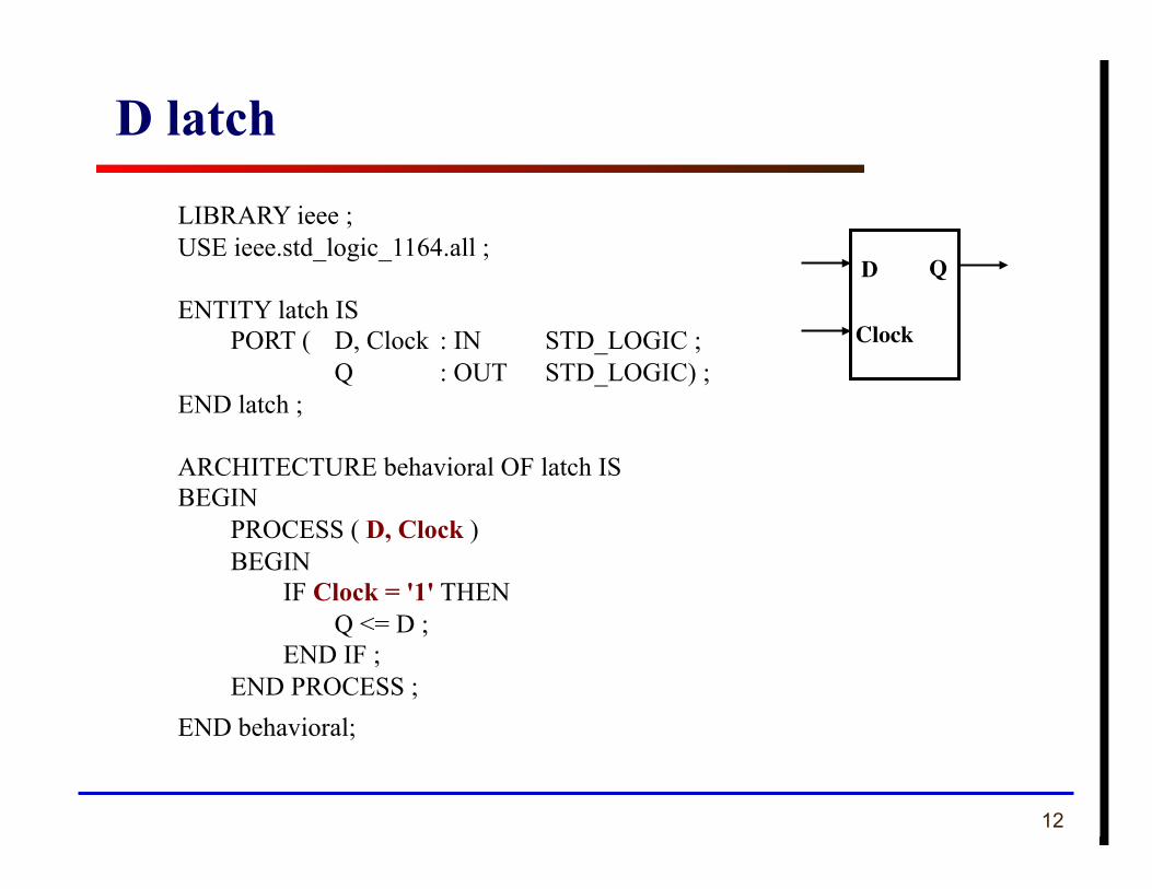
LIBRARY ieee ; USE ieee.std_logic_1164.all ;
ENTITY latch IS PORT ( D, Clock : IN STD_LOGIC ; Q : OUT STD_LOGIC) ;
END latch ;
ARCHITECTURE behavioral OF latch IS BEGIN
PROCESS ( D, Clock ) BEGIN IF Clock = '1' THEN Q <= D ; END IF ; END PROCESS ;
END behavioral;
D latch
D Q
Clock
13
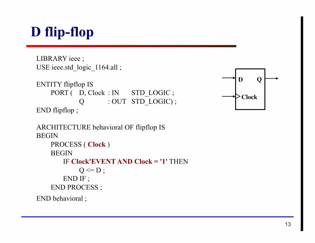
LIBRARY ieee ; USE ieee.std_logic_1164.all ;
ENTITY flipflop IS PORT ( D, Clock : IN STD_LOGIC ; Q : OUT STD_LOGIC) ;
END flipflop ;
ARCHITECTURE behavioral OF flipflop IS BEGIN
PROCESS ( Clock ) BEGIN IF Clock'EVENT AND Clock = '1' THEN Q <= D ; END IF ; END PROCESS ;
END behavioral ;
D flip-flop
D Q
Clock
14
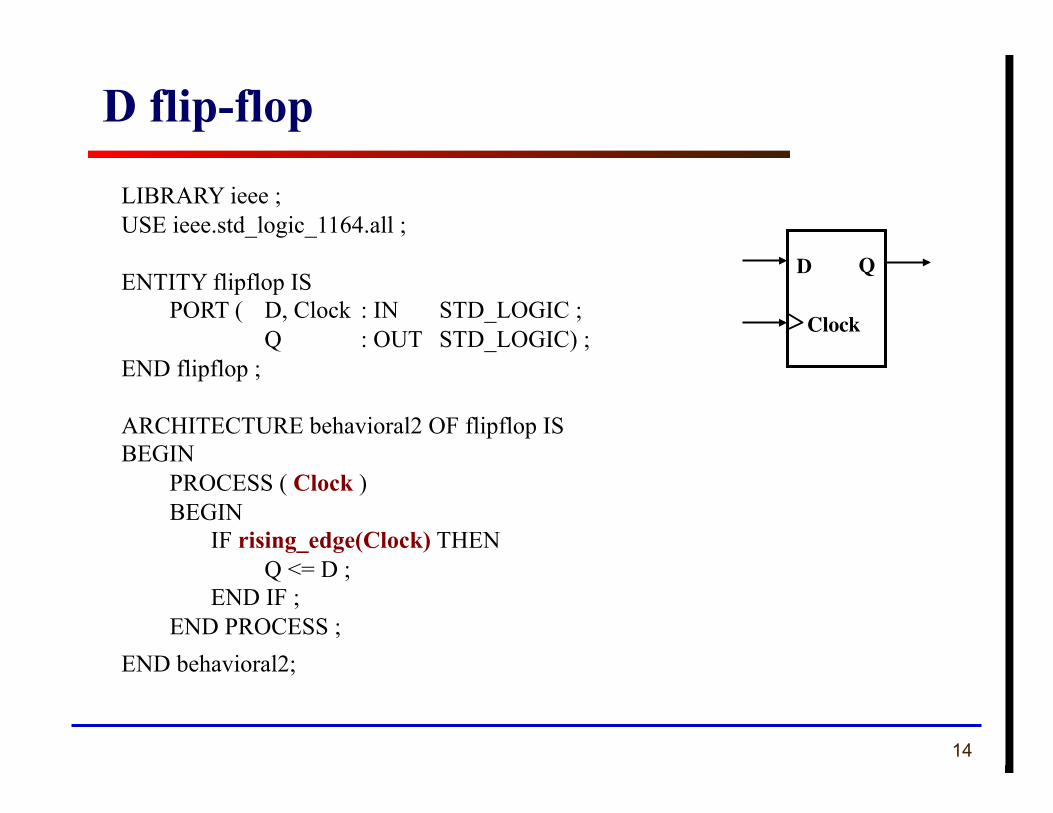
LIBRARY ieee ; USE ieee.std_logic_1164.all ;
ENTITY flipflop IS PORT ( D, Clock : IN STD_LOGIC ; Q : OUT STD_LOGIC) ;
END flipflop ;
ARCHITECTURE behavioral2 OF flipflop IS BEGIN
PROCESS ( Clock ) BEGIN IF rising_edge(Clock) THEN Q <= D ; END IF ; END PROCESS ;
END behavioral2;
D flip-flop
D Q
Clock
15
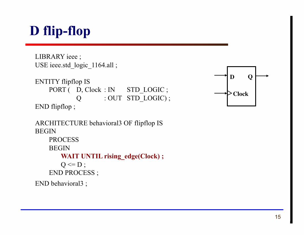
LIBRARY ieee ; USE ieee.std_logic_1164.all ;
ENTITY flipflop IS PORT ( D, Clock : IN STD_LOGIC ; Q : OUT STD_LOGIC) ;
END flipflop ;
ARCHITECTURE behavioral3 OF flipflop IS BEGIN
PROCESS BEGIN WAIT UNTIL rising_edge(Clock) ; Q <= D ; END PROCESS ;
END behavioral3 ;
D flip-flop
D Q
Clock
16
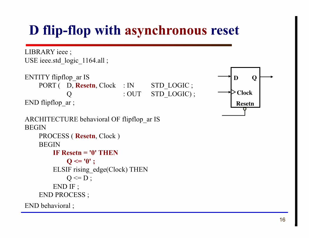
LIBRARY ieee ; USE ieee.std_logic_1164.all ;
ENTITY flipflop_ar IS PORT ( D, Resetn, Clock : IN STD_LOGIC ; Q : OUT STD_LOGIC) ;
END flipflop_ar ;
ARCHITECTURE behavioral OF flipflop_ar IS BEGIN
PROCESS ( Resetn, Clock ) BEGIN IF Resetn = '0' THEN Q <= '0' ; ELSIF rising_edge(Clock) THEN Q <= D ; END IF ; END PROCESS ;
END behavioral ;
D flip-flop with asynchronous reset
D Q
Clock
Resetn
17
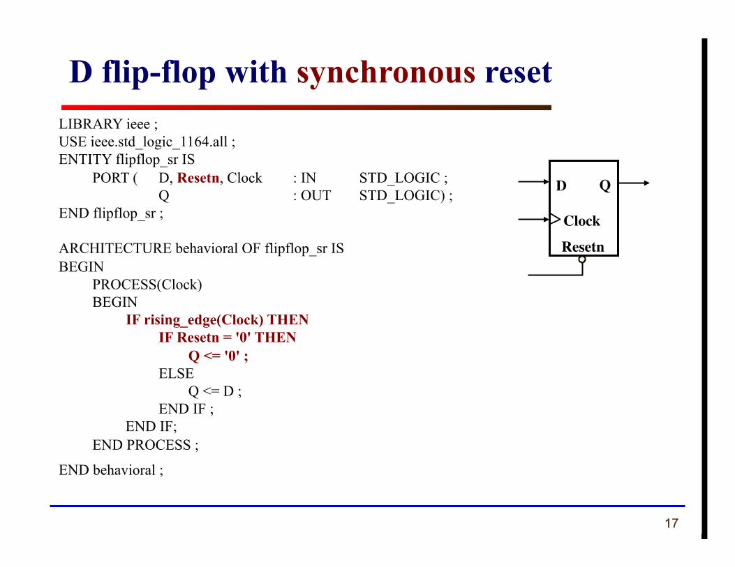
LIBRARY ieee ; USE ieee.std_logic_1164.all ; ENTITY flipflop_sr IS
PORT ( D, Resetn, Clock : IN STD_LOGIC ; Q : OUT STD_LOGIC) ;
END flipflop_sr ;
ARCHITECTURE behavioral OF flipflop_sr IS BEGIN
PROCESS(Clock) BEGIN IF rising_edge(Clock) THEN
IF Resetn = '0' THEN Q <= '0' ; ELSE Q <= D ; END IF ; END IF;
END PROCESS ;
END behavioral ;
D flip-flop with synchronous reset
D Q
Clock
Resetn
18
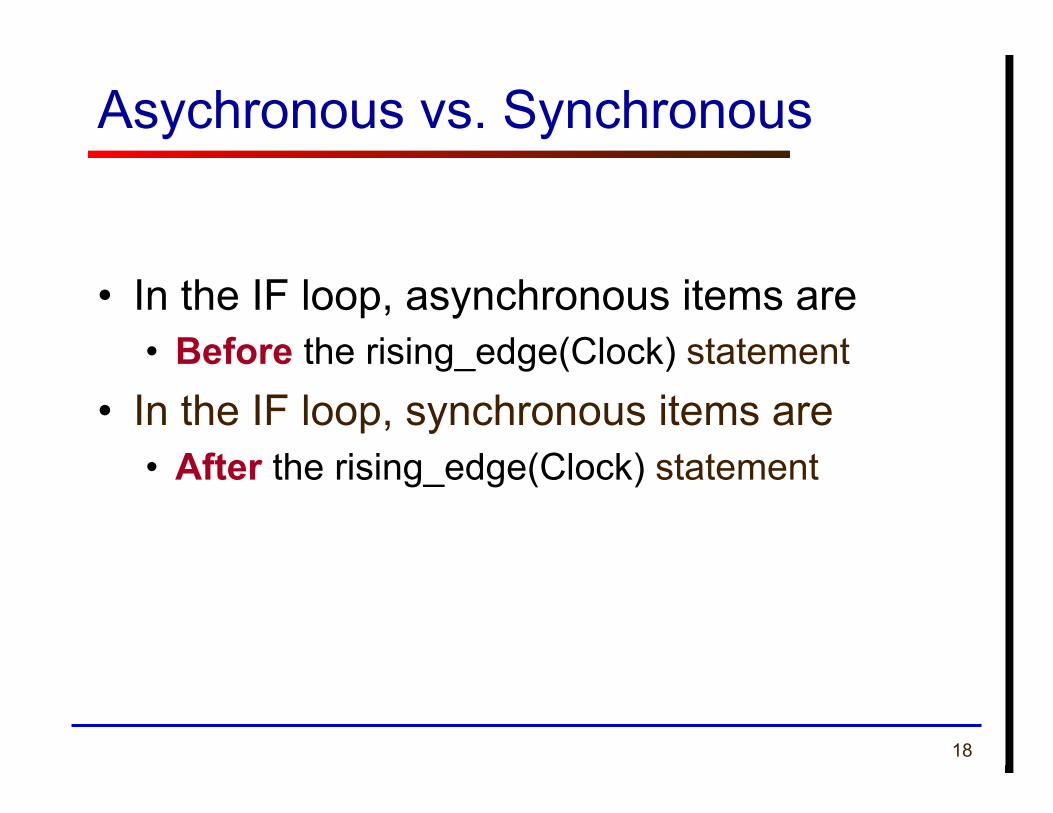
Asychronous vs. Synchronous
• In the IF loop, asynchronous items are • Before the rising_edge(Clock) statement
• In the IF loop, synchronous items are • After the rising_edge(Clock) statement
19
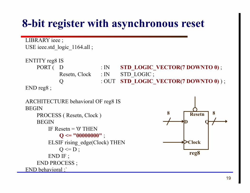
8-bit register with asynchronous reset LIBRARY ieee ; USE ieee.std_logic_1164.all ;
ENTITY reg8 IS PORT ( D : IN STD_LOGIC_VECTOR(7 DOWNTO 0) ; Resetn, Clock : IN STD_LOGIC ; Q : OUT STD_LOGIC_VECTOR(7 DOWNTO 0) ) ;
END reg8 ;
ARCHITECTURE behavioral OF reg8 IS BEGIN
PROCESS ( Resetn, Clock ) BEGIN IF Resetn = '0' THEN Q <= "00000000" ; ELSIF rising_edge(Clock) THEN Q <= D ; END IF ; END PROCESS ;
END behavioral ;`
Resetn
Clock
reg8
8 8
D Q
20
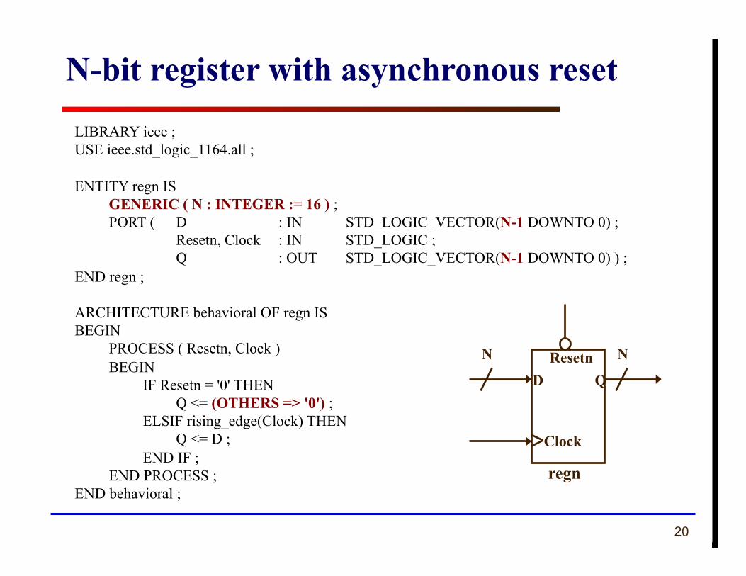
N-bit register with asynchronous reset LIBRARY ieee ; USE ieee.std_logic_1164.all ;
ENTITY regn IS GENERIC ( N : INTEGER := 16 ) ; PORT ( D : IN STD_LOGIC_VECTOR(N-1 DOWNTO 0) ; Resetn, Clock : IN STD_LOGIC ; Q : OUT STD_LOGIC_VECTOR(N-1 DOWNTO 0) ) ;
END regn ;
ARCHITECTURE behavioral OF regn IS BEGIN
PROCESS ( Resetn, Clock ) BEGIN IF Resetn = '0' THEN Q <= (OTHERS => '0') ; ELSIF rising_edge(Clock) THEN Q <= D ; END IF ; END PROCESS ;
END behavioral ;
Resetn
Clock
regn
N N
D Q
21
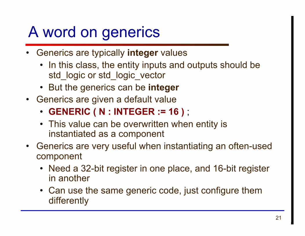
A word on generics • Generics are typically integer values
• In this class, the entity inputs and outputs should be std_logic or std_logic_vector
• But the generics can be integer • Generics are given a default value
• GENERIC ( N : INTEGER := 16 ) ; • This value can be overwritten when entity is
instantiated as a component • Generics are very useful when instantiating an often-used
component • Need a 32-bit register in one place, and 16-bit register
in another • Can use the same generic code, just configure them
differently
22
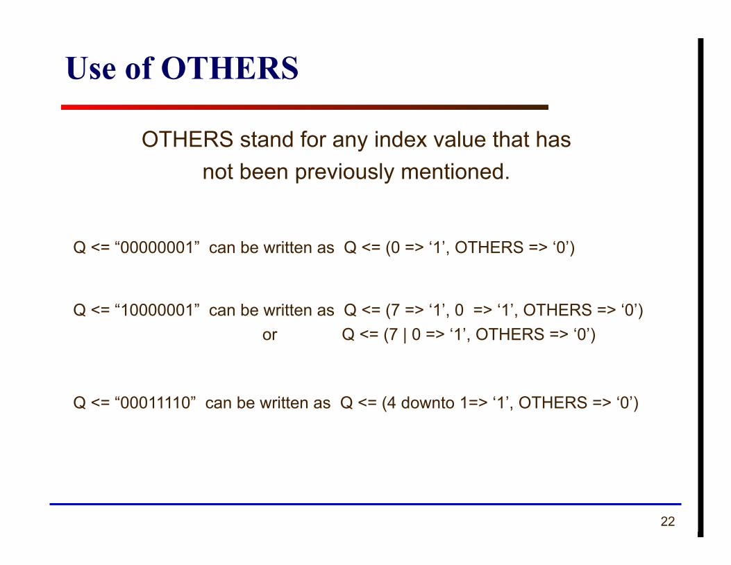
Use of OTHERS
OTHERS stand for any index value that has not been previously mentioned.
Q <= “00000001” can be written as Q <= (0 => ‘1’, OTHERS => ‘0’)
Q <= “10000001” can be written as Q <= (7 => ‘1’, 0 => ‘1’, OTHERS => ‘0’) or Q <= (7 | 0 => ‘1’, OTHERS => ‘0’)
Q <= “00011110” can be written as Q <= (4 downto 1=> ‘1’, OTHERS => ‘0’)
23
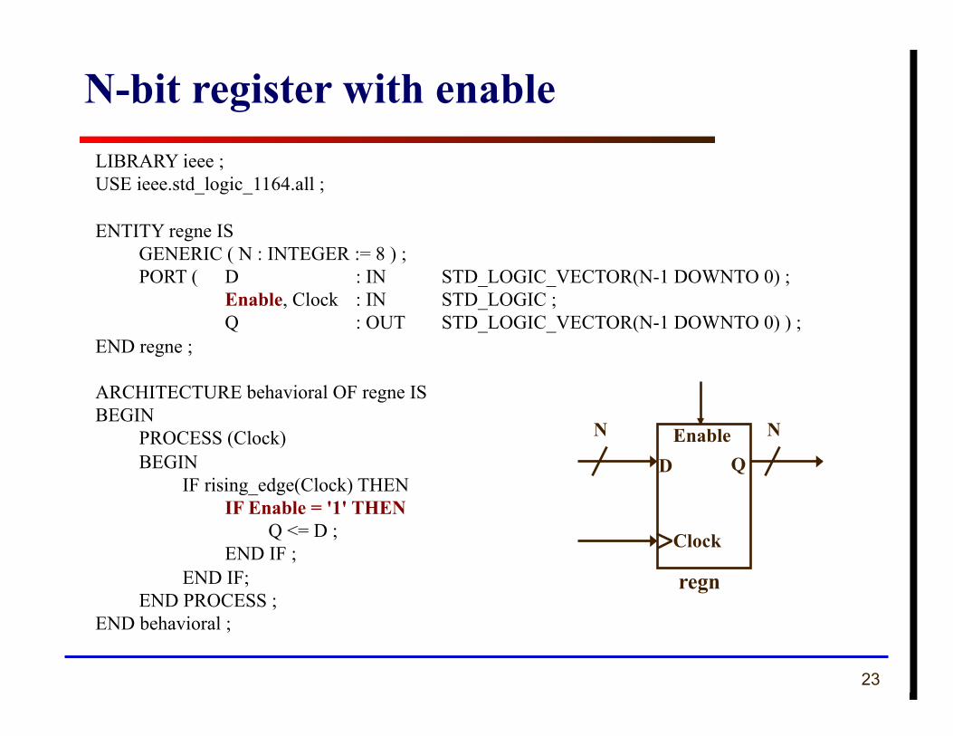
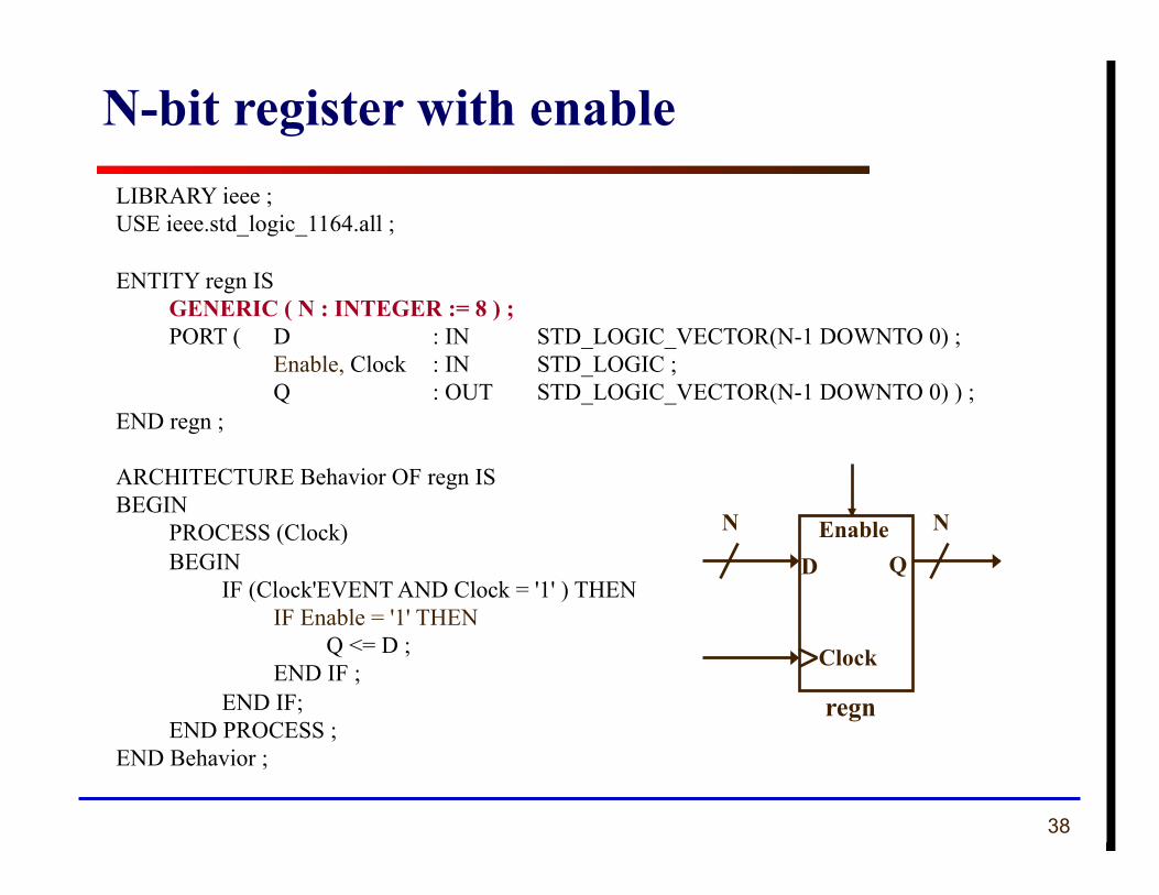
LIBRARY ieee ; USE ieee.std_logic_1164.all ;
ENTITY regne IS GENERIC ( N : INTEGER := 8 ) ; PORT ( D : IN STD_LOGIC_VECTOR(N-1 DOWNTO 0) ; Enable, Clock : IN STD_LOGIC ; Q : OUT STD_LOGIC_VECTOR(N-1 DOWNTO 0) ) ;
END regne ;
ARCHITECTURE behavioral OF regne IS BEGIN
PROCESS (Clock) BEGIN IF rising_edge(Clock) THEN IF Enable = '1' THEN Q <= D ; END IF ; END IF; END PROCESS ;
END behavioral ;
N-bit register with enable
Q DEnable
Clock
regn
N N
24 ECE 448 – FPGA and ASIC Design with VHDL
Counters
25
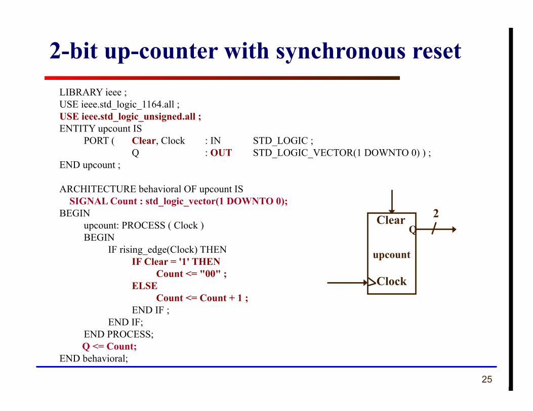
LIBRARY ieee ; USE ieee.std_logic_1164.all ; USE ieee.std_logic_unsigned.all ; ENTITY upcount IS
PORT ( Clear, Clock : IN STD_LOGIC ; Q : OUT STD_LOGIC_VECTOR(1 DOWNTO 0) ) ;
END upcount ;
ARCHITECTURE behavioral OF upcount IS SIGNAL Count : std_logic_vector(1 DOWNTO 0); BEGIN
upcount: PROCESS ( Clock ) BEGIN IF rising_edge(Clock) THEN IF Clear = '1' THEN Count <= "00" ; ELSE Count <= Count + 1 ; END IF ; END IF; END PROCESS;
Q <= Count; END behavioral;
2-bit up-counter with synchronous reset
QClear
Clock
upcount
2
26
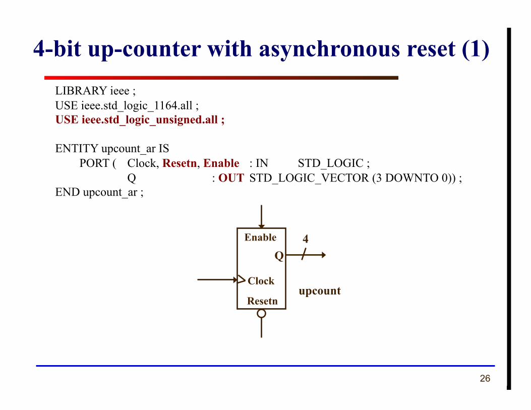
LIBRARY ieee ; USE ieee.std_logic_1164.all ; USE ieee.std_logic_unsigned.all ;
ENTITY upcount_ar IS PORT ( Clock, Resetn, Enable : IN STD_LOGIC ; Q : OUT STD_LOGIC_VECTOR (3 DOWNTO 0)) ;
END upcount_ar ;
4-bit up-counter with asynchronous reset (1)
QEnable
Clock upcount
4
Resetn
27
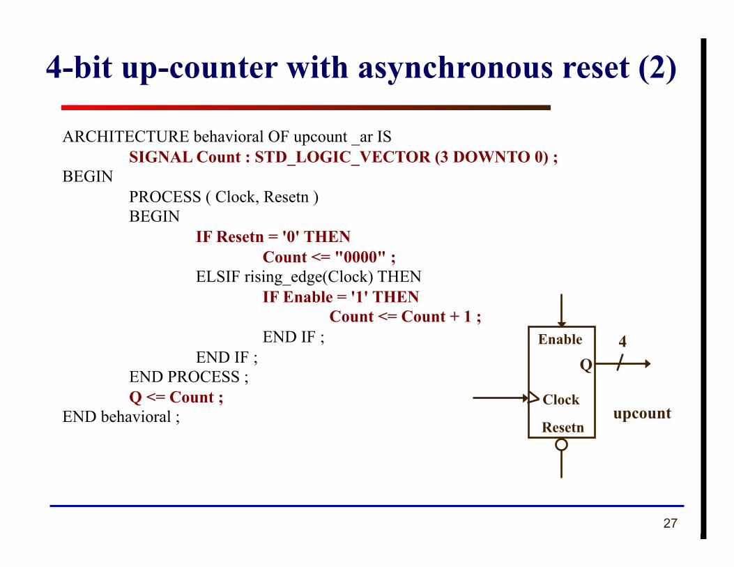
ARCHITECTURE behavioral OF upcount _ar IS SIGNAL Count : STD_LOGIC_VECTOR (3 DOWNTO 0) ;
BEGIN PROCESS ( Clock, Resetn ) BEGIN IF Resetn = '0' THEN Count <= "0000" ; ELSIF rising_edge(Clock) THEN IF Enable = '1' THEN Count <= Count + 1 ; END IF ; END IF ; END PROCESS ; Q <= Count ;
END behavioral ;
4-bit up-counter with asynchronous reset (2)
QEnable
Clock upcount
4
Resetn
28 ECE 448 – FPGA and ASIC Design with VHDL
Shift Registers
29
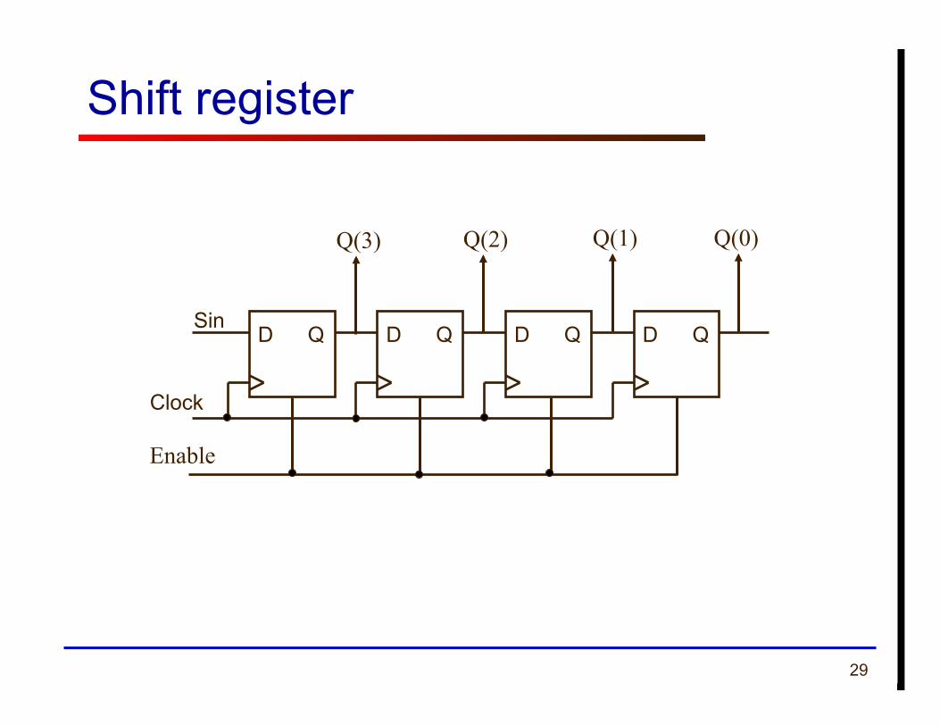
Shift register
D Q Sin
Clock
D Q D Q D Q
Q(3) Q(2) Q(1) Q(0)
Enable
30
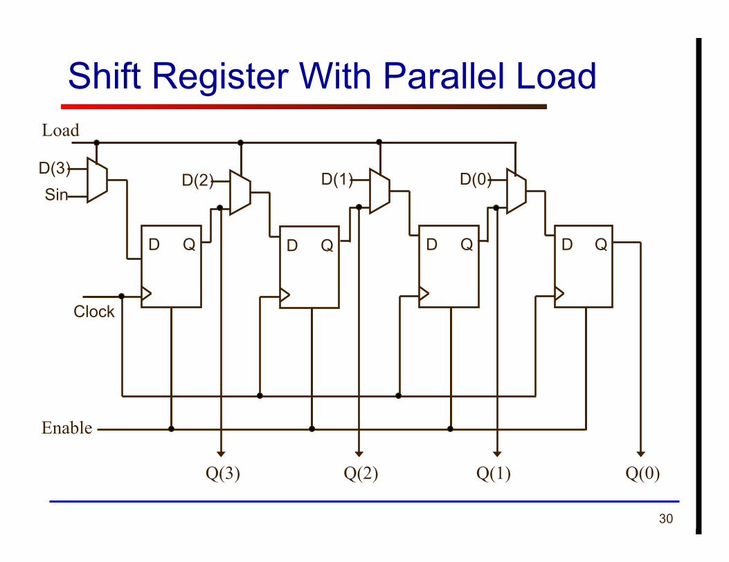
Shift Register With Parallel Load
D(3)
D Q
Clock
Enable
Sin D(2)
D Q
D(1)
D Q
D(0)
D Q
Q(0) Q(1) Q(2) Q(3)
Load
31
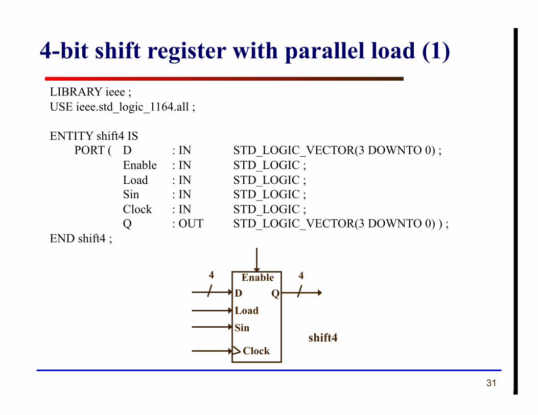
LIBRARY ieee ; USE ieee.std_logic_1164.all ;
ENTITY shift4 IS PORT ( D : IN STD_LOGIC_VECTOR(3 DOWNTO 0) ; Enable : IN STD_LOGIC ; Load : IN STD_LOGIC ; Sin : IN STD_LOGIC ; Clock : IN STD_LOGIC ; Q : OUT STD_LOGIC_VECTOR(3 DOWNTO 0) ) ;
END shift4 ;
4-bit shift register with parallel load (1)
QEnable
Clock shift4
4 D Load Sin
4
32
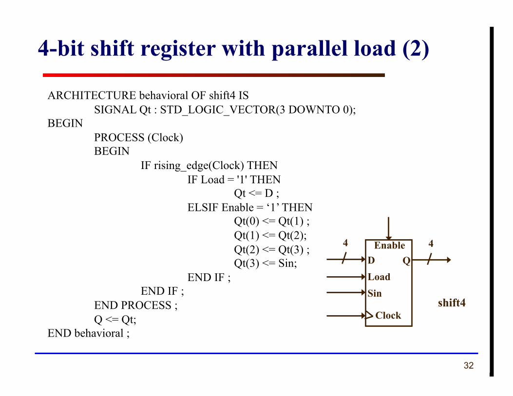
ARCHITECTURE behavioral OF shift4 IS SIGNAL Qt : STD_LOGIC_VECTOR(3 DOWNTO 0);
BEGIN PROCESS (Clock) BEGIN IF rising_edge(Clock) THEN IF Load = '1' THEN Qt <= D ; ELSIF Enable = ‘1’ THEN Qt(0) <= Qt(1) ; Qt(1) <= Qt(2); Qt(2) <= Qt(3) ; Qt(3) <= Sin; END IF ; END IF ; END PROCESS ; Q <= Qt;
END behavioral ;
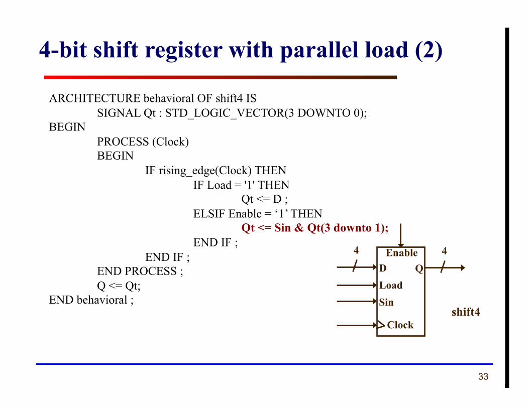
4-bit shift register with parallel load (2)
QEnable
Clock shift4
4 D Load Sin
4
33
ARCHITECTURE behavioral OF shift4 IS SIGNAL Qt : STD_LOGIC_VECTOR(3 DOWNTO 0);
BEGIN PROCESS (Clock) BEGIN IF rising_edge(Clock) THEN IF Load = '1' THEN Qt <= D ; ELSIF Enable = ‘1’ THEN Qt <= Sin & Qt(3 downto 1); END IF ; END IF ; END PROCESS ; Q <= Qt;
END behavioral ;
4-bit shift register with parallel load (2)
QEnable
Clock shift4
4 D Load Sin
4
34
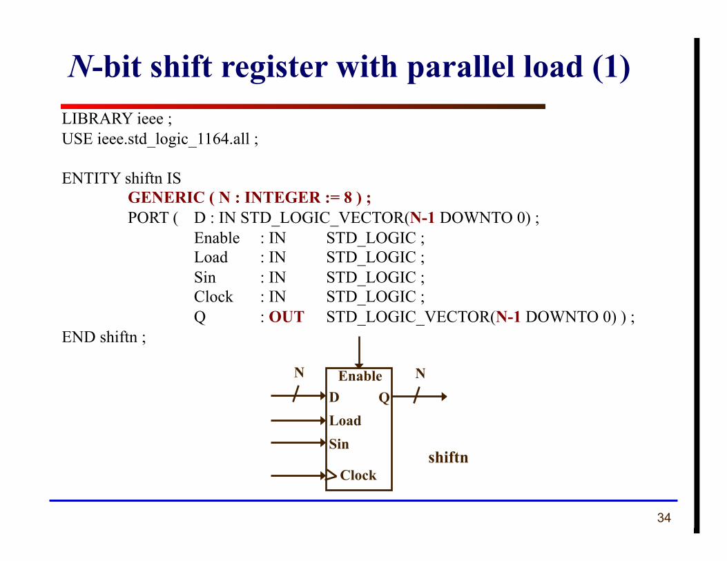
LIBRARY ieee ; USE ieee.std_logic_1164.all ;
ENTITY shiftn IS GENERIC ( N : INTEGER := 8 ) ; PORT ( D : IN STD_LOGIC_VECTOR(N-1 DOWNTO 0) ; Enable : IN STD_LOGIC ; Load : IN STD_LOGIC ; Sin : IN STD_LOGIC ; Clock : IN STD_LOGIC ; Q : OUT STD_LOGIC_VECTOR(N-1 DOWNTO 0) ) ;
END shiftn ;
N-bit shift register with parallel load (1)
QEnable
Clock shiftn
ND Load Sin
N
35
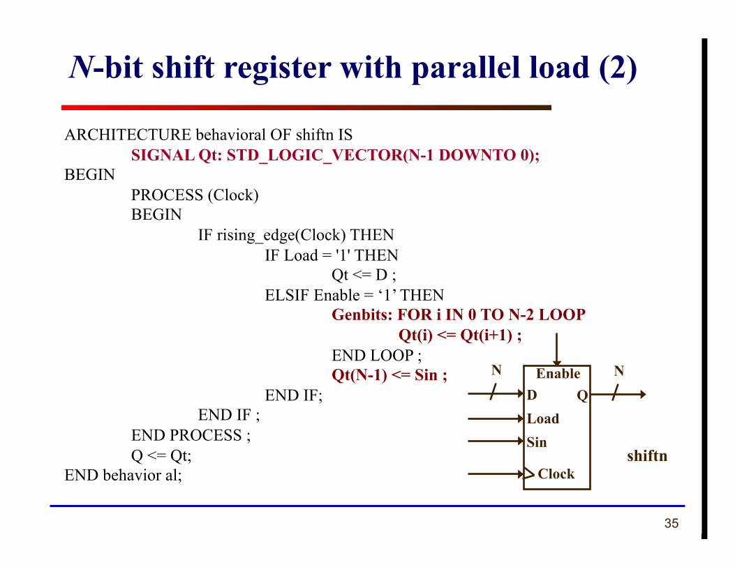
ARCHITECTURE behavioral OF shiftn IS SIGNAL Qt: STD_LOGIC_VECTOR(N-1 DOWNTO 0);
BEGIN PROCESS (Clock) BEGIN IF rising_edge(Clock) THEN IF Load = '1' THEN Qt <= D ; ELSIF Enable = ‘1’ THEN Genbits: FOR i IN 0 TO N-2 LOOP Qt(i) <= Qt(i+1) ; END LOOP ; Qt(N-1) <= Sin ; END IF; END IF ; END PROCESS ; Q <= Qt;
END behavior al;
N-bit shift register with parallel load (2)
QEnable
Clock shiftn
ND Load Sin
N
36 ECE 448 – FPGA and ASIC Design with VHDL
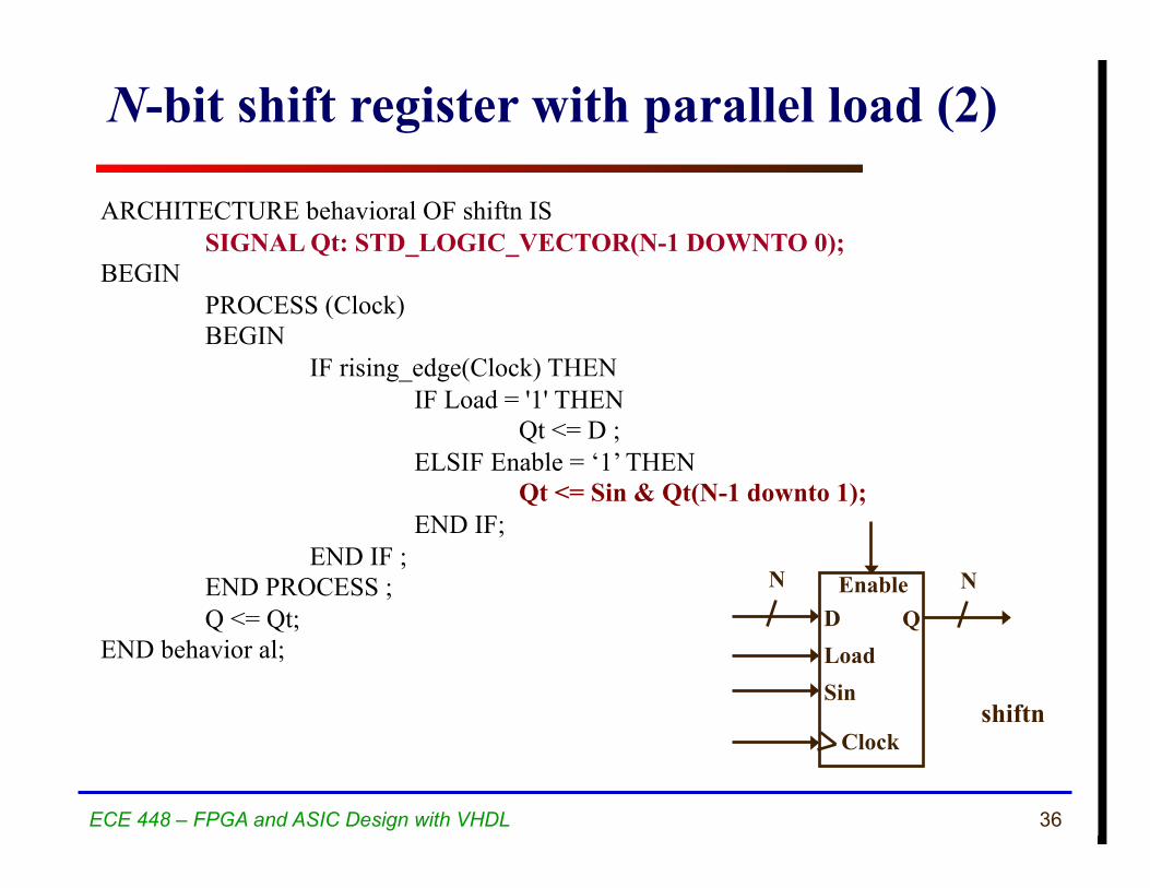
ARCHITECTURE behavioral OF shiftn IS SIGNAL Qt: STD_LOGIC_VECTOR(N-1 DOWNTO 0);
BEGIN PROCESS (Clock) BEGIN IF rising_edge(Clock) THEN IF Load = '1' THEN Qt <= D ; ELSIF Enable = ‘1’ THEN Qt <= Sin & Qt(N-1 downto 1); END IF; END IF ; END PROCESS ; Q <= Qt;
END behavior al;
N-bit shift register with parallel load (2)
QEnable
Clock shiftn
ND Load Sin
N
37 ECE 448 – FPGA and ASIC Design with VHDL
Generic Component Instantiation
38
LIBRARY ieee ; USE ieee.std_logic_1164.all ;
ENTITY regn IS GENERIC ( N : INTEGER := 8 ) ; PORT ( D : IN STD_LOGIC_VECTOR(N-1 DOWNTO 0) ; Enable, Clock : IN STD_LOGIC ; Q : OUT STD_LOGIC_VECTOR(N-1 DOWNTO 0) ) ;
END regn ;
ARCHITECTURE Behavior OF regn IS BEGIN
PROCESS (Clock) BEGIN IF (Clock'EVENT AND Clock = '1' ) THEN IF Enable = '1' THEN Q <= D ; END IF ; END IF; END PROCESS ;
END Behavior ;
N-bit register with enable
Q DEnable
Clock
regn
N N
39
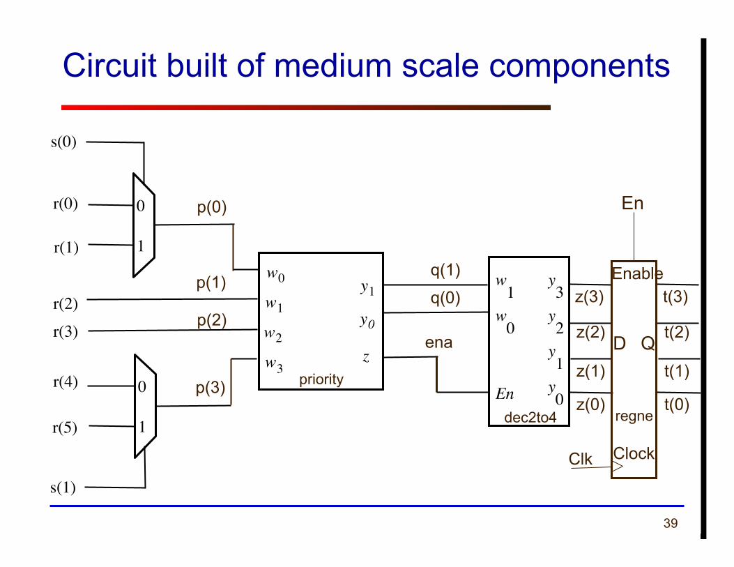
Circuit built of medium scale components
w 0
w 3
y 1 y 0 z
w 1 w 2
w 1
En
y 3
w 0
y 2
y 1
y 0
s(0)
0
1
s(1)
0
1
r(0)
r(1)
r(2) r(3)
r(4)
r(5)
p(0)
p(1)
p(2)
p(3)
q(1)
q(0)
ena
z(3)
z(2)
z(1)
z(0) dec2to4
priority
t(3)
t(2)
t(1)
t(0) regne
D Q
Clk Clock
Enable
En
40
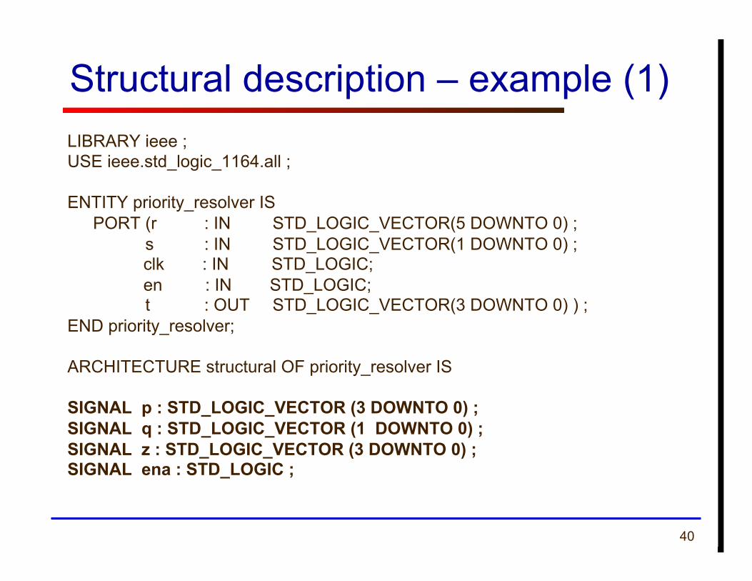
Structural description – example (1) LIBRARY ieee ; USE ieee.std_logic_1164.all ;
ENTITY priority_resolver IS PORT (r : IN STD_LOGIC_VECTOR(5 DOWNTO 0) ; s : IN STD_LOGIC_VECTOR(1 DOWNTO 0) ;
clk : IN STD_LOGIC; en : IN STD_LOGIC;
t : OUT STD_LOGIC_VECTOR(3 DOWNTO 0) ) ; END priority_resolver;
ARCHITECTURE structural OF priority_resolver IS
SIGNAL p : STD_LOGIC_VECTOR (3 DOWNTO 0) ; SIGNAL q : STD_LOGIC_VECTOR (1 DOWNTO 0) ; SIGNAL z : STD_LOGIC_VECTOR (3 DOWNTO 0) ; SIGNAL ena : STD_LOGIC ;
41
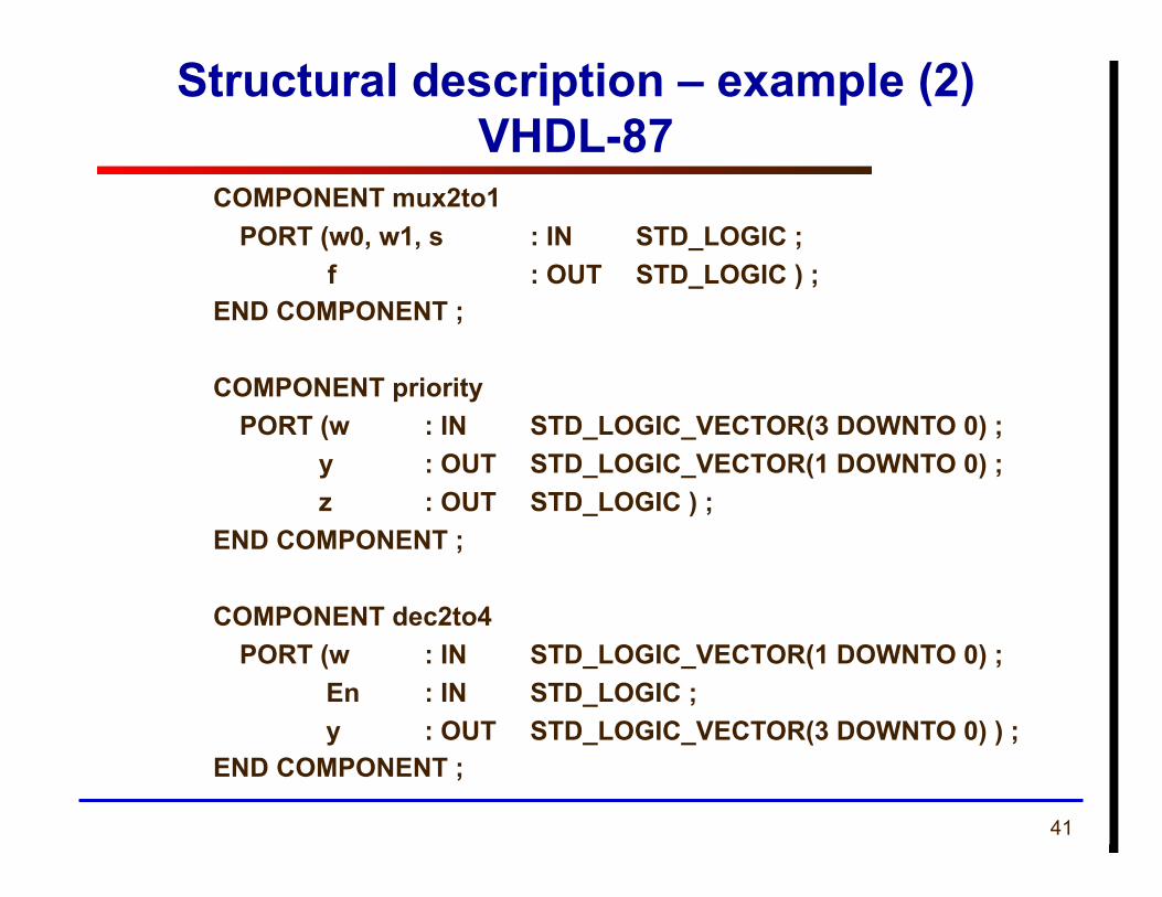
Structural description – example (2) VHDL-87
COMPONENT mux2to1 PORT (w0, w1, s : IN STD_LOGIC ; f : OUT STD_LOGIC ) ;
END COMPONENT ;
COMPONENT priority PORT (w : IN STD_LOGIC_VECTOR(3 DOWNTO 0) ; y : OUT STD_LOGIC_VECTOR(1 DOWNTO 0) ; z : OUT STD_LOGIC ) ;
END COMPONENT ;
COMPONENT dec2to4 PORT (w : IN STD_LOGIC_VECTOR(1 DOWNTO 0) ; En : IN STD_LOGIC ; y : OUT STD_LOGIC_VECTOR(3 DOWNTO 0) ) ;
END COMPONENT ;
42
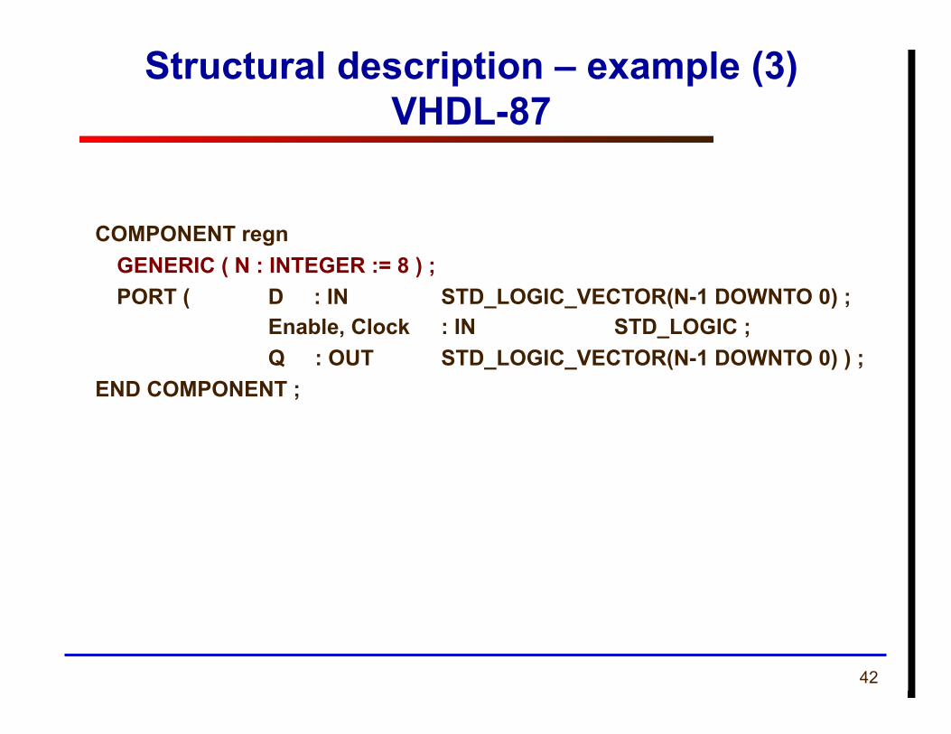
Structural description – example (3) VHDL-87
COMPONENT regn GENERIC ( N : INTEGER := 8 ) ; PORT ( D : IN STD_LOGIC_VECTOR(N-1 DOWNTO 0) ; Enable, Clock : IN STD_LOGIC ; Q : OUT STD_LOGIC_VECTOR(N-1 DOWNTO 0) ) ;
END COMPONENT ;
43
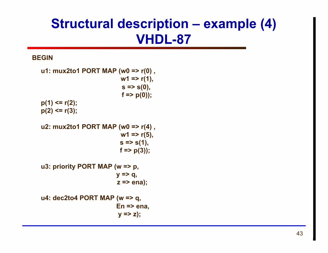
Structural description – example (4) VHDL-87
BEGIN
u1: mux2to1 PORT MAP (w0 => r(0) , w1 => r(1), s => s(0), f => p(0)); p(1) <= r(2);
p(2) <= r(3);
u2: mux2to1 PORT MAP (w0 => r(4) , w1 => r(5), s => s(1), f => p(3));
u3: priority PORT MAP (w => p, y => q,
z => ena);
u4: dec2to4 PORT MAP (w => q, En => ena, y => z);
44
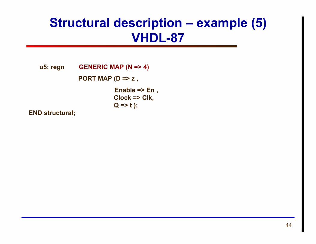
Structural description – example (5) VHDL-87
u5: regn GENERIC MAP (N => 4)
PORT MAP (D => z ,
Enable => En , Clock => Clk, Q => t ); END structural;
45
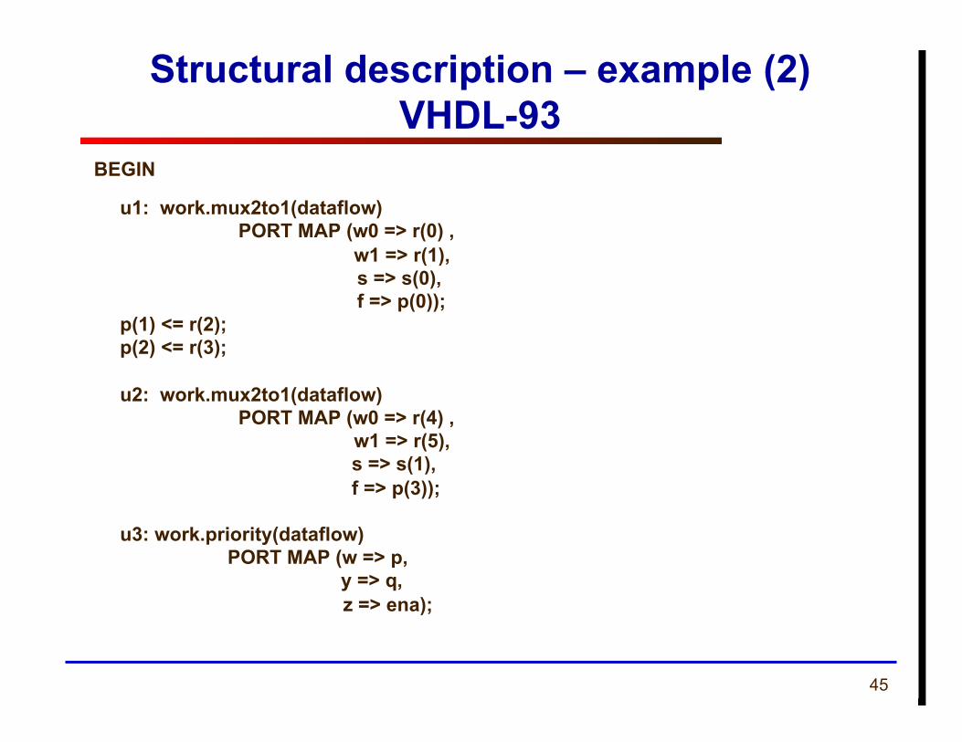
Structural description – example (2) VHDL-93
BEGIN
u1: work.mux2to1(dataflow) PORT MAP (w0 => r(0) , w1 => r(1), s => s(0), f => p(0)); p(1) <= r(2);
p(2) <= r(3);
u2: work.mux2to1(dataflow) PORT MAP (w0 => r(4) , w1 => r(5), s => s(1), f => p(3));
u3: work.priority(dataflow) PORT MAP (w => p, y => q,
z => ena);

46
Structural description – example (5) VHDL-87
u4: work.dec2to4 (dataflow) PORT MAP (w => q, En => ena, y => z);
u5: work.regne(behavioral)
GENERIC MAP (N => 4)
PORT MAP (D => z ,
Enable => En , Clock => Clk, Q => t ); END structural;
47 ECE 448 – FPGA and ASIC Design with VHDL
ROM
48
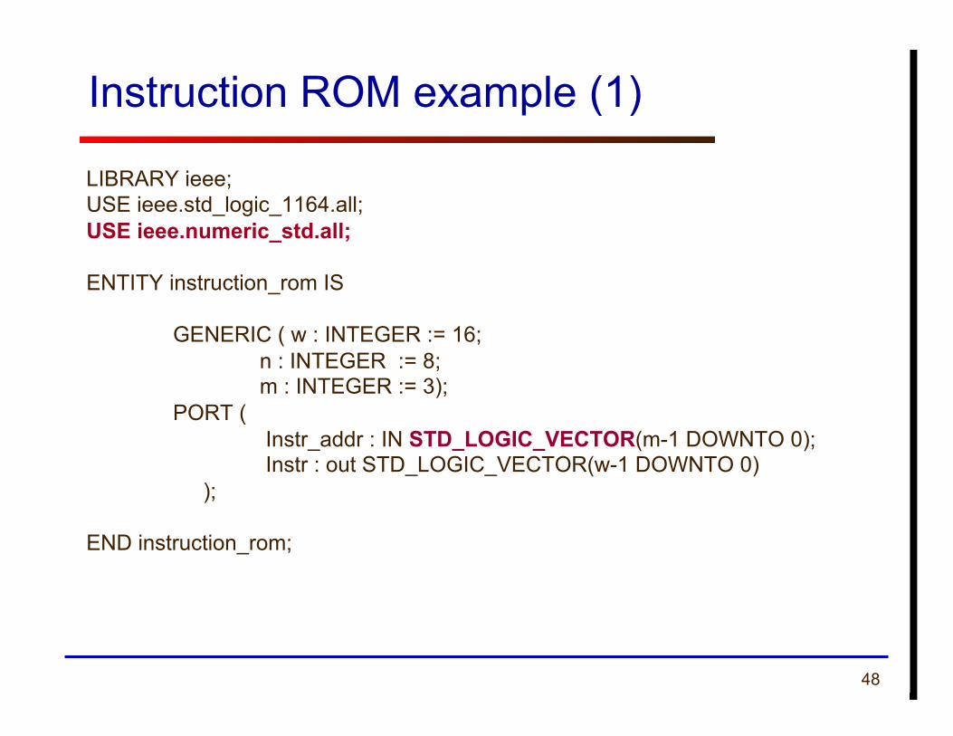
Instruction ROM example (1)
LIBRARY ieee; USE ieee.std_logic_1164.all; USE ieee.numeric_std.all;
ENTITY instruction_rom IS
GENERIC ( w : INTEGER := 16; n : INTEGER := 8; m : INTEGER := 3); PORT ( Instr_addr : IN STD_LOGIC_VECTOR(m-1 DOWNTO 0); Instr : out STD_LOGIC_VECTOR(w-1 DOWNTO 0) );
END instruction_rom;
49
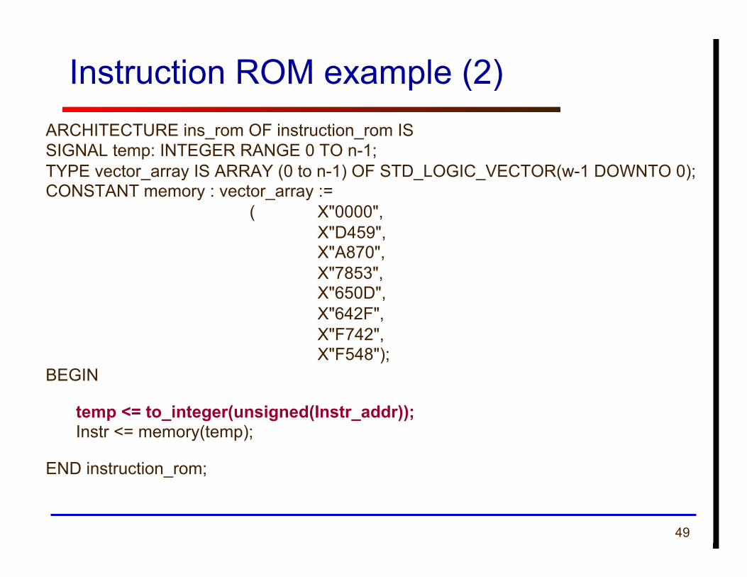
Instruction ROM example (2) ARCHITECTURE ins_rom OF instruction_rom IS SIGNAL temp: INTEGER RANGE 0 TO n-1; TYPE vector_array IS ARRAY (0 to n-1) OF STD_LOGIC_VECTOR(w-1 DOWNTO 0); CONSTANT memory : vector_array :=
( X"0000", X"D459", X"A870", X"7853", X"650D", X"642F", X"F742", X"F548");
BEGIN
temp <= to_integer(unsigned(Instr_addr)); Instr <= memory(temp);
END instruction_rom;
50 ECE 448 – FPGA and ASIC Design with VHDL
Mixing Design Styles Inside of an Architecture
51
VHDL Design Styles
Components and interconnects
structural
VHDL Design Styles
dataflow
Concurrent statements
behavioral
• Registers • Shift registers • Counters • State machines
Sequential statements
synthesizable
52
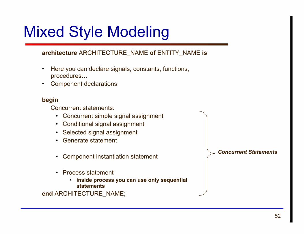
architecture ARCHITECTURE_NAME of ENTITY_NAME is
• Here you can declare signals, constants, functions, procedures…
• Component declarations
begin Concurrent statements:
• Concurrent simple signal assignment • Conditional signal assignment • Selected signal assignment • Generate statement
• Component instantiation statement
• Process statement • inside process you can use only sequential
statements end ARCHITECTURE_NAME;
Mixed Style Modeling
Concurrent Statements
53 ECE 448 – FPGA and ASIC Design with VHDL
Sequential Logic Synthesis for
Beginners
54
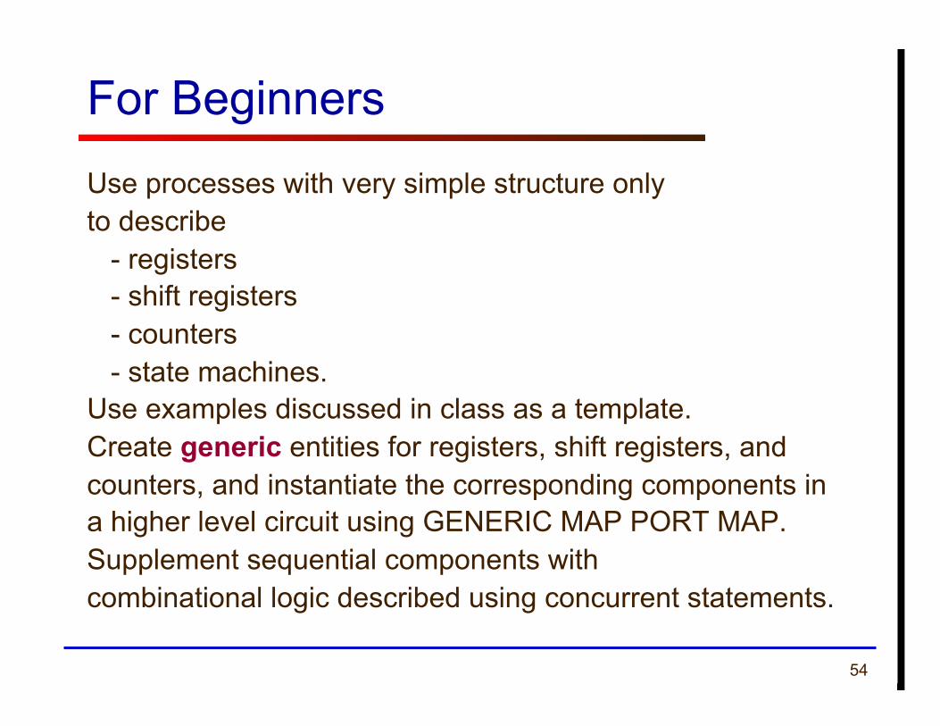
For Beginners Use processes with very simple structure only to describe - registers - shift registers - counters - state machines. Use examples discussed in class as a template. Create generic entities for registers, shift registers, and counters, and instantiate the corresponding components in a higher level circuit using GENERIC MAP PORT MAP. Supplement sequential components with combinational logic described using concurrent statements.
55 ECE 448 – FPGA and ASIC Design with VHDL
Sequential Logic Synthesis for
Intermediates
56
For Intermmediates
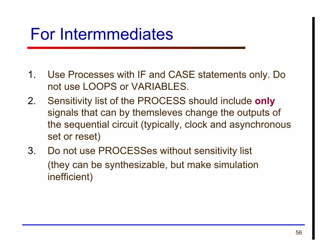
1. Use Processes with IF and CASE statements only. Do not use LOOPS or VARIABLES.
2. Sensitivity list of the PROCESS should include only signals that can by themsleves change the outputs of the sequential circuit (typically, clock and asynchronous set or reset)
3. Do not use PROCESSes without sensitivity list (they can be synthesizable, but make simulation inefficient)
57
For Intermmediates (2)
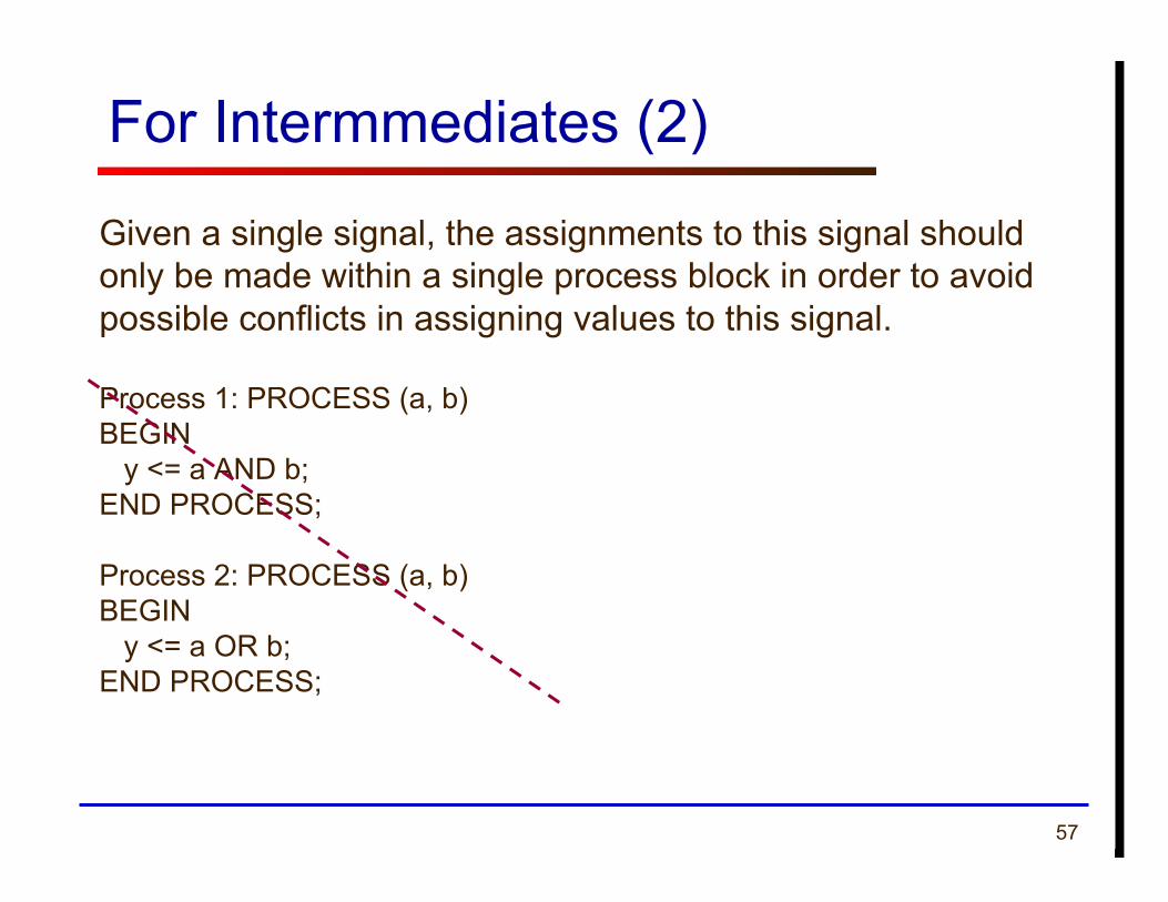
Given a single signal, the assignments to this signal should only be made within a single process block in order to avoid possible conflicts in assigning values to this signal.
Process 1: PROCESS (a, b) BEGIN y <= a AND b; END PROCESS;
Process 2: PROCESS (a, b) BEGIN y <= a OR b; END PROCESS;
George Mason University
Non-synthesizable VHDL
59
Delays
Delays are not synthesizable
Statements, such as wait for 5 ns a <= b after 10 ns will not produce the required delay, and should not be used in the code intended for synthesis.
60
Initializations
Declarations of signals (and variables) with initialized values, such as SIGNAL a : STD_LOGIC := ‘0’; cannot be synthesized, and thus should be avoided. If present, they will be ignored by the synthesis tools. Use set and reset signals instead.
61
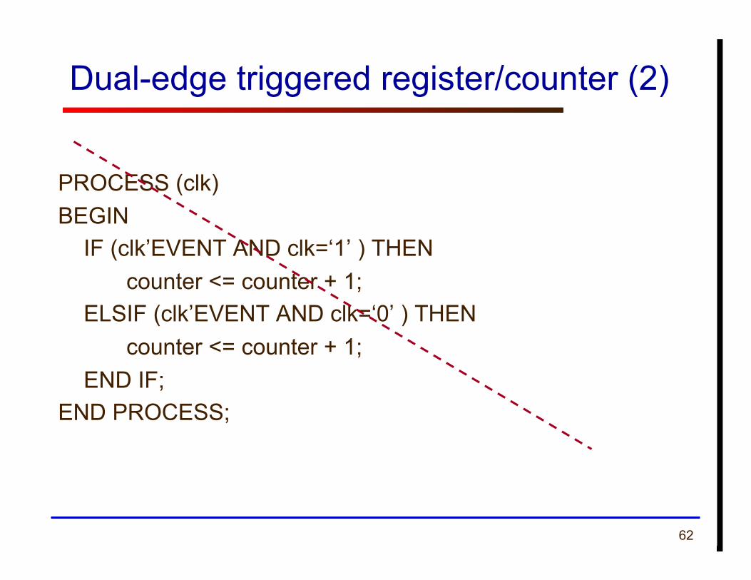
Dual-edge triggered register/counter (1)
In FPGAs register/counter can change only at either rising (default) or falling edge of the clock.
Dual-edge triggered clock is not synthesizable correctly, using either of the descriptions provided below.
62
Dual-edge triggered register/counter (2)
PROCESS (clk) BEGIN
IF (clk’EVENT AND clk=‘1’ ) THEN counter <= counter + 1; ELSIF (clk’EVENT AND clk=‘0’ ) THEN counter <= counter + 1;
END IF; END PROCESS;
63
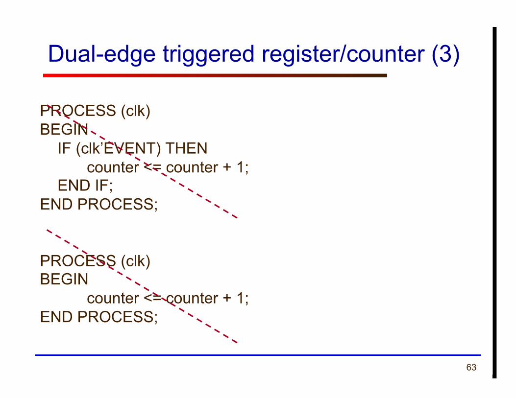
Dual-edge triggered register/counter (3)
PROCESS (clk) BEGIN
IF (clk’EVENT) THEN counter <= counter + 1; END IF;
END PROCESS;
PROCESS (clk) BEGIN
counter <= counter + 1; END PROCESS;