ece/cs 552: pipeliningpages.cs.wisc.edu/.../spring2017//handouts/lecnotes/08_pipelining.pdf ·...
TRANSCRIPT

ECE/CS 552: Pipelining
© Prof. Mikko Lipasti
Lecture notes based in part on slides created by Mark Hill, David Wood, Guri Sohi, John Shen and Jim Smith

Pipelining
• Forecast – Big Picture
– Datapath
– Control

Motivation
• Single cycle implementation
– CPI = 1
– Cycle = imem + RFrd + ALU + dmem + RFwr + muxes + control
– E.g. 500+250+500+500+250+0+0 = 2000ps
– Time/program = P x 2ns
Instructions Cycles
Program Instruction
Time
Cycle
(code size)
X X
(CPI) (cycle time)

Multicycle
• Multicycle implementation:
Cycle:
Instr:
1 2 3 4 5 6 7 8 9 10
11
12
13
i F D X M W
i+1 F D X
i+2 F D X M
i+3 F
i+4

Multicycle
• Multicycle implementation
– CPI = 3, 4, 5
– Cycle = max(memory, RF, ALU, mux, control)
– = max(500,250,500) = 500ps
– Time/prog = P x 4 x 500 = P x 2000ps = P x 2ns
• Would like:
– CPI = 1 + overhead from hazards (later)
– Cycle = 500ps + overhead
– In practice, ~3x improvement

Big Picture
• Instruction latency = 5 cycles
• Instruction throughput = 1/5 instr/cycle
• CPI = 5 cycles per instruction
• Instead
– Pipelining: process instructions like a lunch buffet
– ALL microprocessors use it
• E.g. Intel Core i7, AMD Jaguar, ARM A9

Big Picture
• Instruction Latency = 5 cycles (same)
• Instruction throughput = 1 instr/cycle
• CPI = 1 cycle per instruction
• CPI = cycle between instruction completion = 1

Ideal Pipelining
• Bandwidth increases linearly with pipeline depth
• Latency increases by latch delays
GateDelay
Comb. Logicn Gate Delay
GateDelay
L GateDelayL
L GateDelayL Gate
DelayL
L BW = ~(1/n)
n--2
n--2
n--3
n--3
n--3
BW = ~(2/n)
BW = ~(3/n)

Example: Integer Multiplier
9
16x16 combinational multiplier
ISCAS-85 C6288 standard benchmark
Tools: Synopsys DC/LSI Logic 110nm gflxp ASIC
[Source: J. Hayes, Univ. of Michigan]

Example: Integer Multiplier
Configuration Delay MPS Area (FF/wiring) Area Increase
Combinational 3.52ns 284 7535 (--/1759)
2 Stages 1.87ns 534 (1.9x) 8725 (1078/1870) 16%
4 Stages 1.17ns 855 (3.0x) 11276 (3388/2112) 50%
8 Stages 0.80ns 1250 (4.4x) 17127 (8938/2612) 127%
10
Pipeline efficiency
2-stage: nearly double throughput; marginal area cost
4-stage: 75% efficiency; area still reasonable
8-stage: 55% efficiency; area more than doubles
Tools: Synopsys DC/LSI Logic 110nm gflxp ASIC

Ideal Pipelining
Cycle:
Instr:
1 2 3 4 5 6 7 8 9 10
11
12
13
i F D X M W
i+1 F D X M W
i+2 F D X M W
i+3 F D X M W
i+4 F D X M W

Pipelining Idealisms
• Uniform subcomputations
– Can pipeline into stages with equal delay
• Identical computations
– Can fill pipeline with identical work
• Independent computations
– No relationships between work units
– No dependences, hence no pipeline hazards
• Are these practical?
– No, but can get close enough to get significant speedup

Complications
• Datapath
– Five (or more) instructions in flight
• Control
– Must correspond to multiple instructions
• Instructions may have
– data and control flow dependences
– I.e. units of work are not independent
• One may have to stall and wait for another

Datapath

Datapath

Control
• Control
– Concurrently set by 5 different instructions
– Divide and conquer: carry IR down the pipe

Pipelined Datapath
• Start with single-cycle datapath • Pipelined execution
– Assume each instruction has its own datapath
– But each instruction uses a different part in every cycle
– Multiplex all on to one datapath
– Latches separate cycles (like multicycle)
• Ignore dependences and hazards for now
– Data
– control

Pipelined Datapath
Instruction
memory
Address
4
32
0
AddAdd
result
Shift
left 2
Instr
uctio
n
IF/ID EX/MEM MEM/WB
M u x
0
1
Add
PC
0Write data
M u x
1
Registers
Read data 1
Read data 2
Read register 1
Read register 2
16Sign
extend
Write register
Write data
Read data
1
ALU result
M u x
ALU
Zero
ID/EX
Data
memory
Address

Pipelined Datapath
• Instruction flow
– add and load
– Write of registers
– Pass register specifiers
• Any info needed by a later stage gets passed down the pipeline
– E.g. store value through EX
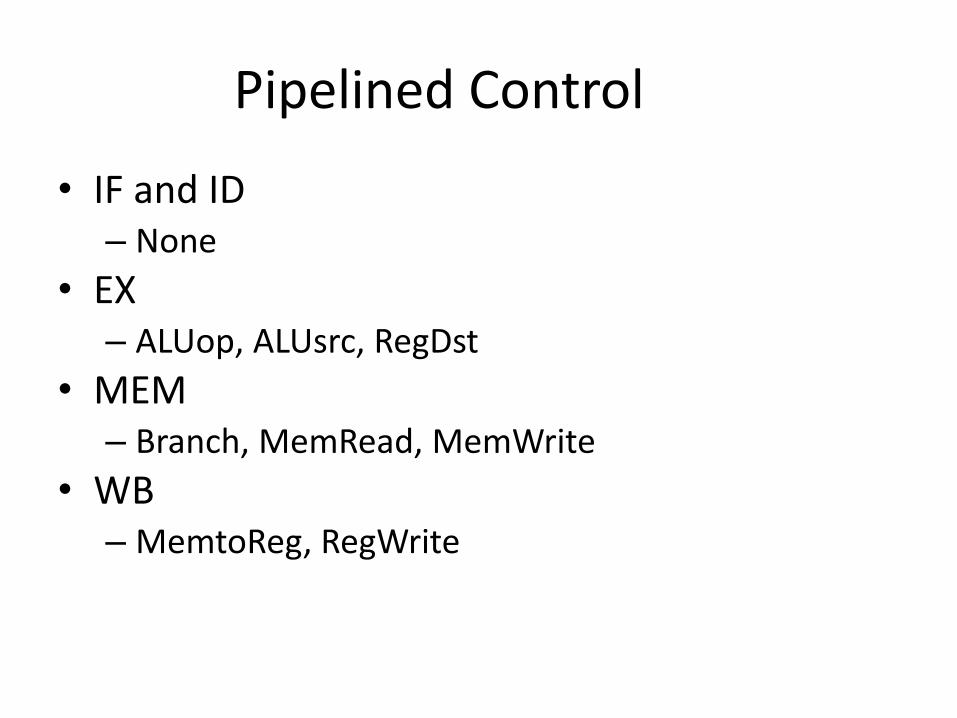
Pipelined Control
• IF and ID – None
• EX – ALUop, ALUsrc, RegDst
• MEM – Branch, MemRead, MemWrite
• WB – MemtoReg, RegWrite
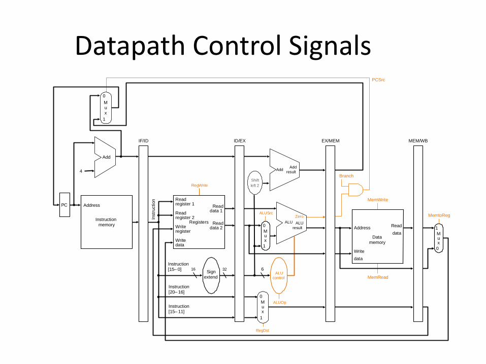
Datapath Control Signals
PC
Instruction memory
Address
Instr
uction
Instruction [20– 16]
MemtoReg
ALUOp
Branch
RegDst
ALUSrc
4
16 32
Instruction [15– 0]
0
0Registers
Write register
Write data
Read data 1
Read data 2
Read register 1
Read register 2
Sign extend
M u x
1Write
data
Read
data M u x
1
ALU
control
RegWrite
MemRead
Instruction [15– 11]
6
IF/ID ID/EX EX/MEM MEM/WB
MemWrite
Address
Data memory
PCSrc
Zero
AddAdd
result
Shift
left 2
ALU
result
ALU
Zero
Add
0
1
M u x
0
1
M u x

Pipelined Control
Control
EX
M
WB
M
WB
WB
IF/ID ID/EX EX/MEM MEM/WB
Instruction

All Together
PC
Instruction memory
Instr
uctio
n
Add
Instruction [20– 16]
Me
mto
Re
g
ALUOp
Branch
RegDst
ALUSrc
4
16 32Instruction [15–0]
0
0
M u x
0
1
AddAdd
result
RegistersWrite register
Write data
Read data 1
Read data 2
Read register 1
Read register 2
Sign extend
M u x
1
ALU result
Zero
Write data
Read data
M u x
1
ALU control
Shift left 2
Re
gW
rite
MemRead
Control
ALU
Instruction [15– 11]
6
EX
M
WB
M
WB
WBIF/ID
PCSrc
ID/EX
EX/MEM
MEM/WB
M u x
0
1
Me
mW
rite
Address
Data memory
Address

Pipelined Control
• Controlled by different instructions
• Decode instructions and pass the signals down the pipe
• Control sequencing is embedded in the pipeline
– No explicit FSM
– Instead, distributed FSM

Summary
• Big Picture • Datapath • Control • Next
– Program dependences – Pipeline hazards