ecen/mae 3723 – systems i matlab lecture 2. lecture overview what is simulink? how to use simulink...
TRANSCRIPT
ECEN/MAE 3723 – Systems I
MATLAB Lecture 2

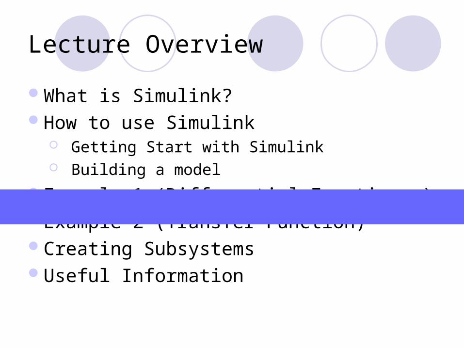
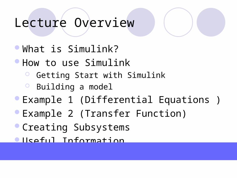
Lecture Overview
What is Simulink?How to use Simulink
Getting Start with Simulink Building a model
Example 1 (Differential Equations )Example 2 (Transfer Function)Creating SubsystemsUseful Information

What is Simulink? (1)
A software package for modeling, simulating, and analyzing dynamic systems.
Supports linear and nonlinear systems, modeled in continuous time, sample time, or a hybrid of the two.
Systems can also be multirate (i.e. different parts that are sampled or updated at different rates)

What is Simulink? (2)
For modeling, it provides a graphical user interface (GUI) for building models as block diagrams (using click-and-drag mouse operations)
Can build models in hierarchical fashion (using both top-down and bottom-up approaches)
You can simulate, analyze the output results, explore, revise your models and have FUN!

Lecture Overview
What is Simulink?How to use Simulink
Getting Start with Simulink Building a model
Example 1 (Differential Equations )Example 2 (Transfer Function)Creating SubsystemsUseful Information

Start a Simulink Session
Type simulinkon Matlab command window
Click on the SIMULINK icon on toolbar

Simulink Library Browser
SEARCH windowCREAT NEW MODEL icon
BLOCK set for model construction
LIBRARY

Create a New Model
CREAT NEW MODEL icon
Workspace where youconstruct your model

Lecture Overview
What is Simulink?How to use Simulink
Getting Start with Simulink Building a model
Example 1 (Differential Equations )Example 2 (Transfer Function)Creating SubsystemsUseful Information

Building a Model
Simulink Block Diagram – pictorial model of a dynamic system
Each block represents an elementary dynamic system that produces an output (either continuous or discrete output)
Lines represent connections of block inputs to block outputs
u(Input)
x(states)
y(Output)

Building a Model (2)
The following steps will guide you to construct a system/model:
STEP 1: Creating Blocks
STEP 2: Making connections
STEP 3: Set Parameters
STEP 4: Running Simulation

Building a Model (3)
Step 1: Creating Blocks
Click-Drag-Drop the Sine Wave block to Workspace Window
This is the Sine Wave block is
from the Sources library
Sources library
Save this model

Building a Model (4)
Step 1: Creating Blocks
These arefrom the
Sinks library
The Gain block isfrom the
Math library
The Mux block is from the Signals &Systems library

Building a Model (5)
Step 2: Making connectionsTo make connection: left-click while holding down control key (on keyboard) and drag from source port to a destination port
A connected Model

Building a Model (6)
Gain value = 5
Name the output parameter as “out1”
Double click the Gain block to set the parameter for the Gain block
Step 3: Set Parameters

Building a Model (7)
click “simulation parameters” to set up the desired parameters
You can change the “stop time” and then click the “OK button”
Click here to run the simulation
Step 4: Running Simulation

Building a Model (8)
View output via Scope block
Double click on Scope block to display output of the scopeNote: Scope block is similar to oscilloscope!
Output of the scope
Yellow: Input sine wavePurple: Output (sine wave with gain of 5
To fit graph to frame
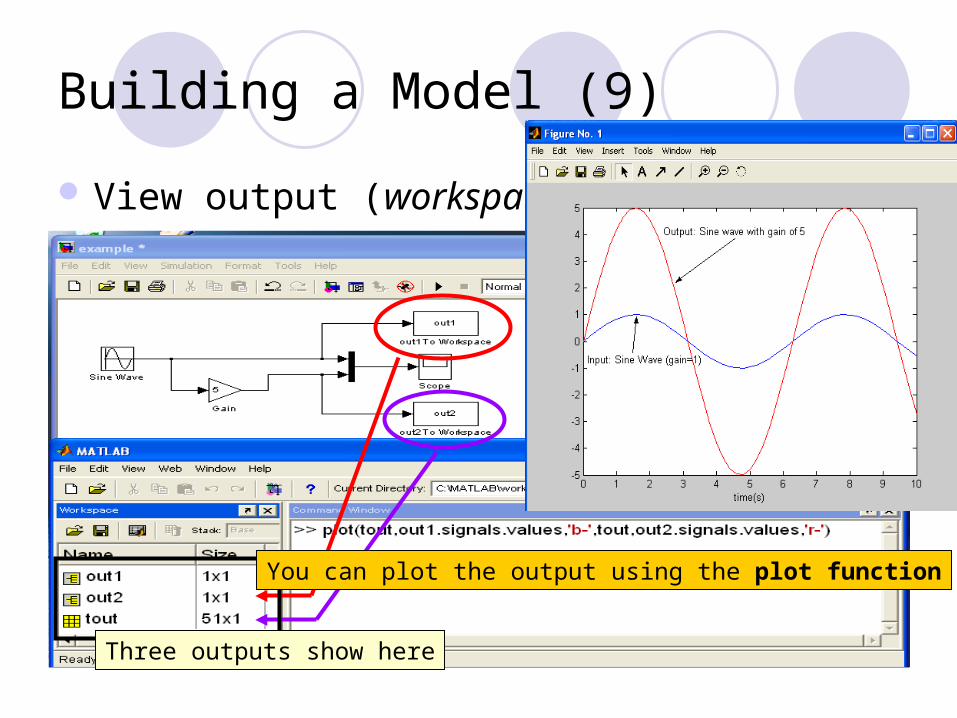
Building a Model (9)
Three outputs show here
View output (workspace)
You can plot the output using the plot function
Lecture Overview
What is Simulink?How to use Simulink
Getting Start with Simulink Building a model
Example 1 (Differential Equations )Example 2 (Transfer Function)Creating SubsystemsUseful Information
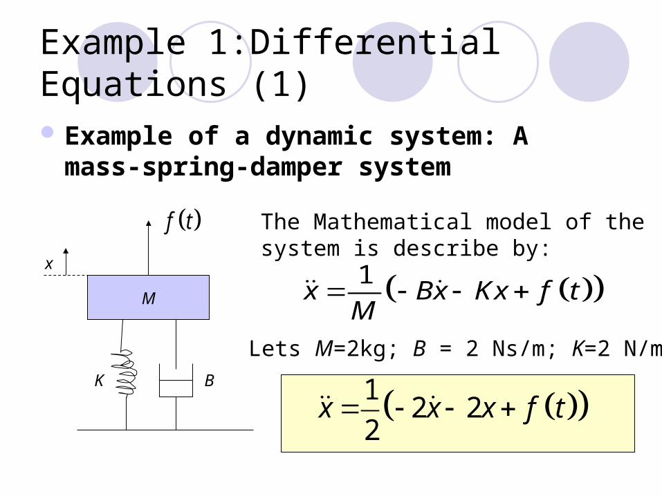
Example 1:Differential Equations (1)
Example of a dynamic system: A mass-spring-damper system
1x Bx Kx f t
M
The Mathematical model of the system is describe by:
M
K B
x
f t
12 2
2x x x f t
Lets M=2kg; B = 2 Ns/m; K=2 N/m

Unit Step Input
Example 1:Differential Equations (2)
Use Simulink to simulate the step response of the system, i.e.
STEP 1: Creating Blocks
12 2
2x x x f t
f(t), N
1
0 Time, s
Select BLOCK set Location in Simulink Library
Step Sources
Sum Math Operation
Gain Math Operation
Integrator Continuous
Scope & To Workspace Sinks
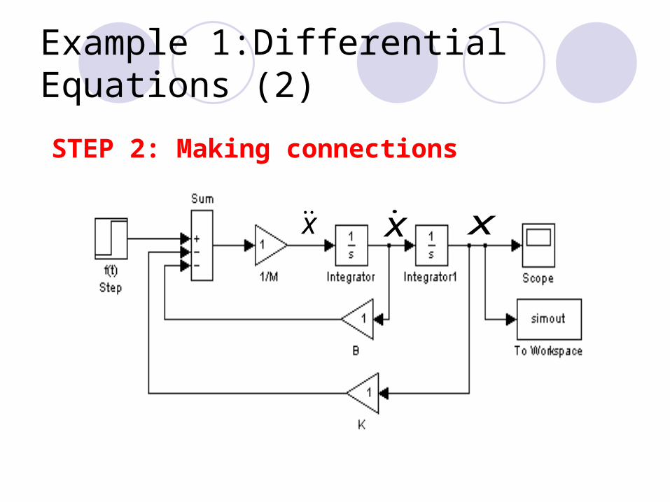
Example 1:Differential Equations (2)
x x
STEP 2: Making connections
x

Example 1:Differential Equations (3)
STEP 3: Set Parameters
x x x
Set Step time =0
Note: Assume all initial conditions = 0

Example 1:Differential Equations (4)
STEP 4: Running Simulation
Open “simulation parameters” window
Set “Stop time” = 30
12
RUNSimulation

Example 1:Differential Equations (5)
Step Response for the mass-spring-damper system example
Output from Scope block Plot system response

Lecture Overview
What is Simulink?How to use Simulink
Getting Start with Simulink Building a model
Example 1 (Differential Equations )Example 2 (Transfer Function)Creating SubsystemsUseful Information

Example 2: Transfer Function (1)
Use the same mass-spring-damper system example and simulate the response using transfer function approach
12 2
2x x x f t
2
( ) 1
( ) 2 2 2
X s
F s s s
The transfer function of the equation (assume all initial conditions =0)

Example 2: Transfer Function (2)
STEP 1: Creating Blocks
Select BLOCK set Location in Simulink Library
Step Sources
Transfer Function Continuous
Scope & To Workspace Sinks

Example 2: Transfer Function (3)
STEP 2: Making connections
x
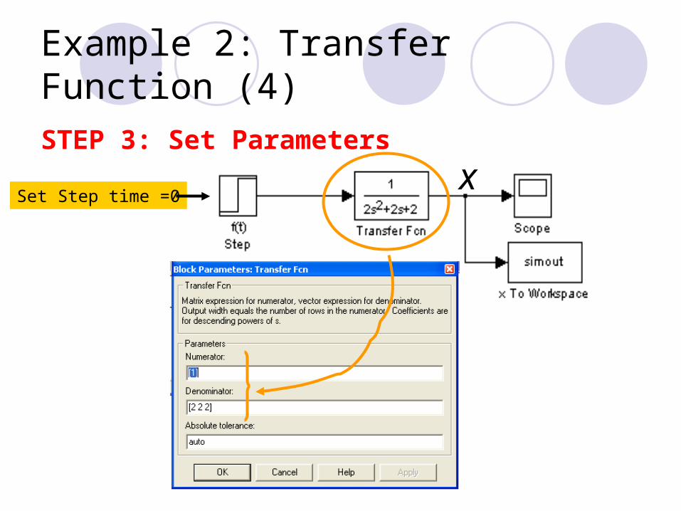
Example 2: Transfer Function (4)
xSet Step time =0
STEP 3: Set Parameters

Example 2: Transfer Function (5)
STEP 4: Running Simulation
Open “simulation parameters” window
Set “Stop time” = 30
12
RUNSimulation

Example 2: Transfer Function (6)
Same output as before (Slide 21)
Output from Scope block Plot system response

Lecture Overview
What is Simulink?How to use Simulink
Getting Start with Simulink Building a model
Example 1 (Differential Equations )Example 2 (Transfer Function)Creating SubsystemsUseful Information
Creating Subsystems (1)
Subsystem – similar to “Subroutine”Advantage of Subsystems:
Reduce the number of blocks display on the main window (i.e. simplify the model)
Group related blocks together (i.e. More organized)
Can create a hierarchical block diagram (i.e. you can create subsystems within a subsystem )
Easy to check for mistakes and to explore different parameters
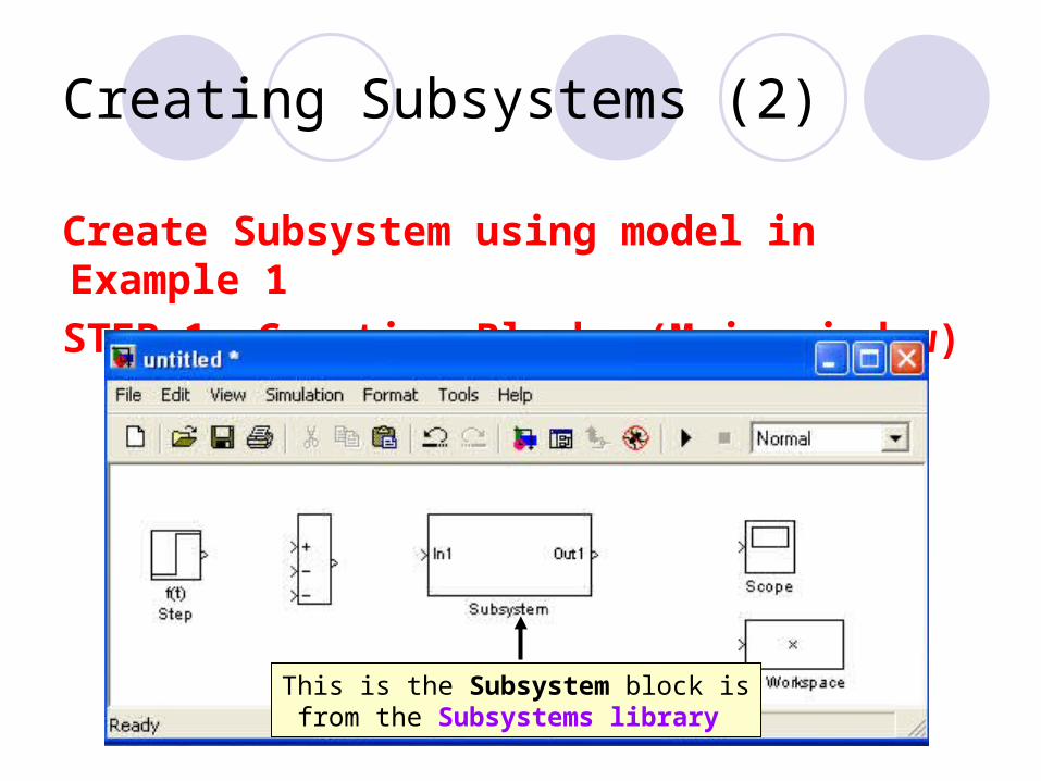
Creating Subsystems (2)
Create Subsystem using model in Example 1
STEP 1: Creating Blocks (Main window)
This is the Subsystem block isfrom the Subsystems library
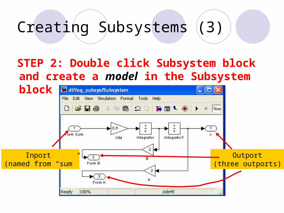
Creating Subsystems (3)
STEP 2: Double click Subsystem block and create a model in the Subsystem block
Inport (named from “sum”
Outport(three outports)

Creating Subsystems (4)
STEP 3: Making connections (Main window)

Creating Subsystems (5)
STEP 4: Set Parameter (Main window)
STEP 5: Running Simulation
Then view output response
Output from Scope block
Lecture Overview
What is Simulink?How to use Simulink
Getting Start with Simulink Building a model
Example 1 (Differential Equations )Example 2 (Transfer Function)Creating SubsystemsUseful Information

Useful Information (1)
Ramp Function
Set Slope
Set Start time for Ramp function
Set initial value
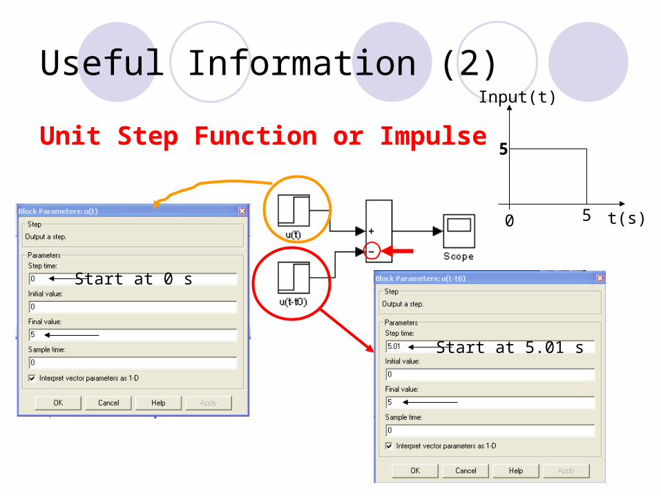
Useful Information (2)
Unit Step Function or Impulse
t(s)50
5
Input(t)
Start at 5.01 s
Start at 0 s

Useful Information (3)
To run programs, have to be in the current active directory or in a directory in the path (goto File Set path... )
To copy the SIMULINK Model from Simulink Workspace and add to report (Edit Copy model to clipboard)
Need help on SIMULINK (At Simulink Library Browser Click Help)