ecl 246 tip tanks for the beech super king air
DESCRIPTION
Tip Tanks for the Beech Super King AirTRANSCRIPT

Engineering Case Library
TIP TANKS FOR THE BEECH SUPER KING AIR
To increase the range of a twin engine airplane, extrafuel tanks must be designed and integrated with othersytems. The project involves activities ranging fromdrafting and cost estimation, to vibration testing andlightning strike tests . Doug Marwill and two otherengineers at Beechcraft spend about a year on themodification; they deal with vendors and subcontractors,as well as with the Federal Aviation Administration.
q\ 1982 by the American Society for Engineering Education.Prepared by R. D. Marwill at Wichita State Universityunder the supervision of J. A. Alic.

1
TIP TANKS FOR THE BEECH
ECL 246A
SUPER KING AIR
Part A
The Tank Design
Beech Aircraft Corporation, with headquarters in Wichita, Kansas, is one ofthe world's largest producers of general aviation aircraft. The companywas founded in 1§32 by Mr. and Mrs. Walter H. Beech. After the death ofWalter Beech in 1950, Mrs. 0. A. Beech became President and is still activein the company today as Chairman of the Board of Directors.
Beech Aircraft is known worldwide as a manufacturer of superiorquality aircraft beginning with a two place single engine plane up to thetwin turboprop, 15 passenger Super King Air Model 200. Today the companyemploys more than 8,000 people with sales totalling more than $400,000,000annually
.
The Model 200 Super King Air is one of the most successful sellingaircraft Beech has ever built. Three hundred of these top-of-the-lineaircraft have been built in approximately three years. This is an impressiveproduction record for an aircraft whose average cost is over $1 million each.This aircraft is now one of the most popular Beech models and a continuousbacklog of orders remains as new applications for its use continue to grow.In 1975, one of these new applications arose when a customer asked for anaircraft which could fly 2300 nautical miles without refueling. The mosteconomical solution to the requirement appeared to be the addition of fuel tankson the wing tips of a Model 200. But as Doug Marwill and Gene Nusz, two designengineers in the Propulsion Systems Group, were to find out, it would be abusy 12-month project with some challenging design hurdles.
The basic Model 200, Exhibit A-l, is an 8 to 15 passenger pressurizedall-weather turboprop transport aircraft which was introduced in December,1973. Its maximum range at standard day conditions and 31,000 ft. altitudeis 1887 nautical miles (nm) . The proposed extended range turboprop Model 200Twas to be identical to the basic Model 200 except for a stronger wing designedto carry a 52 gallon fuel tank on each wing tip. This extra 104 gallons offuel would be required to extend the aircraft's flying distance another 445 nm.
Doug Marwill pointed out, "A project of this nature requires support fromalmost every engineering group in the Production Engineering Division." AtBeech, the Aircraft Engineering Department is divided into two divisions:Research and Development, and Production Engineering. For this particularproject, the Production Engineering Division was to design, develop and FAAcertify the wing tip tank design. The organization chart, Exhibit A-2, showsthe breakdown of the groups within the Production Engineering Division.


a <2 <
1-
z111
QUJ ^ s
V-t
c»- ujUJ UJ 2UZ s
_. >U Eto
zUJto
t/i
CC wUJ %LU zz I
ro
z 01
Lu oU
?d
LL X -s
Zcc wLU 5LU Lil
PZ Q_
wfor
LU ^cc— 6
sb X2 DKg
CCa.
ECL 246A
§52 -J
LU <co O
CO« UJ
« ?: C3CC 2 u
oUJ UJ I
is u."
o z u2 ccUJ -,
H
> "J< 2K |
tin
UJ 2uj UJ X2 z(3 g
<a.
UJ ">
£ cc
O D2 h-uj O°- ?
= 2UJ Ouj O2 h-
to
Eh-< CA> i
cc VJ 0
EE AL 3z u
CC
(3
Z TR XUJ
ELE
CCLULU cc
z o o 0)
z cc
zLU
-I TE CC
Q- TY z X3 CO
ROX
o
cc
EE oO
z CO _J
.ngiARE HAU /enig
Q. ccCO
LUo CO >LU
LUt~ O a:
o X.cca.
HHMHUSXw
ccUJ ouj Ed
>O a.Z co ELU " LU
t- -JCC
LU Q2 o >
inCO
8"
. OCO CO
•'Dell
^£111
*
oLU
MODI
i
Z co-
ts OJ
2 °>
UJ o"t- ro
O _JUj uj
si
TZ I-
z oUJ Ol
X<-> _1
5
LU CO
U UJZ -5
5 o
° ^UJ *I
O <

4 ECL 246A
The Model 200 project group (Block 1 in Exhibit A-2) is responsible forcoordinating all the engineering efforts of the other groups involved inthis tip tank design project. Mr. L. B. Clay, the project engineer for thisprogram, had the job of coordinating the efforts of the support engineeringgroups to keep the project on schedule and to resolve major design problemsas they occurred.
One of these support groups is the Systems Engineering group (Block 2)which itself includes several subgroups. One of these subgroups is theMechanical Systems group which is responsible for all environmental systems,cockpit control systems, anti-icing systems, flight control and landing gearsystems. A second subgroup within Systems Engineering is the ElectricalEngineering group which is responsible for all aircraft electrical designexcept avionics (airborne electronics). Avionics is consolidated into anothersubgroup. Still another subgroup is Styling and Interiors. Their task isto design the cabin interior equipment and arrangement which will best suitthe customer's needs. This includes everything from seats, ashtrays andliquor bars to cargo handling equipment or camera installations for terrainmapping.
Another major group is Technical Engineering (Block 3), consisting ofStructures, Weight Control and Aerodynamics. The Structures subgroup is
responsible for ensuring adequate strength levels in the aircraft structure.They are responsible for seeing that any changes and modifications haveadequate structural strength and do not adversely effect the safety of theaircraft. This subgroup does not design aircraft structure but only providesanalytical support for other groups. The Weight Control subgroup is responsiblefor monitoring the effects of changes or modifications on the aircraft'stotal weight and its overall balance. The Aerodynamics subgroup must providepredicted flight characteristics due to changes or modifications to theaircraft.
The last group shown in Exhibit A-2 is Propulsion Systems (Block 4),which is composed of the Turbine Engine group and Piston Engine group. Thisgroup has the responsibility for design of the fuel systems and engineinstallations on all Beech aircraft. In this particular project, the TurbineEngine group, where Doug Marwill and Gene Nusz worked, was given the responsibilityfor the design of the wing tip tank and its operation in conjunction withthe aircraft's main fuel system.
Doug Marwill had joined Beech Aircraft as a design engineer in 1969 andhad been assigned to the Production Engineering Turbine Propulsion Systemsgroup since that time. Gene Nusz had been assigned to the Propulsion Systemsgroup in Research and Development until 1973. At that time, he joined theProduction Propulsion Systems group, working mainly on the newly FAA certifiedModel 200.
5 ECL 246A
The tip tank project began in October, 1975, when a prospective customer
approached Beech Aircraft with the idea of building a special purpose aircraft
to be used for aerial photography. The most difficult specification was that
the aircraft be able to stay airborne for at least 11 hours. Engineering
was asked to determine if it was feasible to stretch the Model 200 's flying
time from 9.5 hours to 11 hours. The first concern was to determine how many
gallons of fuel would be required to fly for 11 hours.
Doug said, "Engine fuel consumption rates are given as lbs/hr/hp. From
previous flight testing, we knew how much fuel was required for taxi,
takeoff, climb, cruise, and descent. But the length of time to perform these
maneuvers is a function of aircraft weight. Therefore, we first had to know
the new weight of the aircraft! This was a problem since weight cannot be
calculated until fuel quantity is known and fuel quantity, determined by fuel
consumption, cannot be found until aircraft weight is known. Fortunately, it
is easy to use trial and error for such a problem, since we know that it takes
a pretty big change in weight to have much effect on the fuel consumption."
Taking previous cruise fuel consumption rates at an aircraft gross weight
of 12,500 lb and assuming a new aircraft weight of 13,500 lb at takeoff, Doug
found the total flying time required 3,585 lb of fuel (560 gallons) when the
aircraft was at 25,000 ft under standard day conditions. Previous test data
indicated this gross weight would require 95 lb of fuel for taxi and takeoff , 230 lb
for climb, 165 lb for descent and 270 lb for emergency reserve. This gave a
total of 4,345 lb (650 gallons) of fuel for an 11 hour mission. The zero-fuel
weight of the aircraft, including all special mission equipment, was 9,250 lb.
This gave a total weight of 13,595 lb with fuel, minus 95 lb for taxiing, leaving
13,500 lb gross weight at lift-off. Doug said, "Several iterations are
often required to find the correct combination of weight and fuel consumption
before total fuel quantity required can be determined." After finishing his
calculations, Doug found that 104 gallons of additional fuel would be required.
Doug said, "The next question to be answered was where to put the 104
gallons of fuel! Two possibilities had been talked about. The first suggestion
was to put all of the additional fuel in one tank inside the fuselage. This
idea was an economical one from a cost and time standpoint because it required
little modification to the aircraft. But it had some serious disadvantages.
First of all, it is dangerous to store fuel in a passenger compartment. Second,
it occupied valuable space required by the customer's mission equipment. And
third, it presented a center of gravity balance problem for the aircraft.
"The other proposal was to build a fuel tank mounted on the external
surface of the wing tip," he continued. "The advantages were that it did not
increase the wing fatigue bending moment in flight because it would be located
on that portion of the wing which was flying or supporting itself. It also did
not occupy usable cabin space and could easily be lengthened in the future to
gain additional fuel. This aspect seemed favorable from the standpoint of future
sales.
"
6 ECL 246A
"However, this proposal also had some drawbacks. The modification wouldrequire strengthening of the wing to support the additional dynamic loads onthe wing during landings caused by the added weight at the wing tip . Flighttesting would be needed to determine what effect the tip tanks would have onaircraft performance. And we would have to worry about protecting the tiptanks from lightning strikes, which usually occur on the nose, tail or wingtips of an aircraft."
The wing tip tank proposal was chosen by Engineering management becauseit appeared to be most promising for future use on other special missionaircraft, as well as other models in the Beech line. This decision by Engineering was sent to the Marketing Department within two weeks and presented to
the potential customer for his evaluation. A few days later, a formal "ModelSpecification" was submitted to the potential customer providing essentialpredicted aircraft performance data. Excerpts from the Model Specificationare given in Exhibit A-3. This specification gave data on the approximatesize and location of the tanks, their usable fuel quantity, fuel systemsoperation, and fuel gauging system. Other information such as optional equip-ment, special equipment and special modifications were also listed in theModel Specification.
Several weeks passed before Beech was again contacted by the potentialcustomer. At this time, the customer indicated approval of the proposaland asked for a price on the aircraft as specified in the Model Specification.This occurred in December, 1975, and was the real beginning of the project forDoug and Gene. It was at this point that Doug was asked to "bid" the job of
designing a 52 gallon fuel tip tank for the Model 200T, as the new model wasto be designated. Doug said, "The term 'bid* means that an engineer is giventhe job of looking at the project and deciding how it will be done. At thispoint, I looked at the project for any major problems in the system design or
operation. Minor problems and exact details are not evaluated at this time."
"Manufacturers of major subassemblies and system components such as fuelquantity measuring systems, electrical components, fuel valves, etc., werecontacted to help determine the feasibility of the proposed project," Doug wenton. "The Federal Aviation Administration (FAA) was formally contacted byletter and asked to determine what regulations would apply to this modificationAlso, since this customer was from France, the French equivalent to our FAAwas contacted to determine if they had any special regulations on this classof aircraft."
Doug said, "The first major task was compliance with FAA regulations.In the United States, all fixed wing aircraft are basically divided into twoclassifications determined by gross weight. All aircraft manufactured byBeech Aircraft and most other general aviation companies are under 12,500 lb,
the arbitrary dividing point established by the FAA. If an aircraft exceedsthis weight, it must conform to a completely different set of regulations.Since the Model 200T was going to have a gross weight of 13,595 lbs, we hadto find a means of staying legal so the rules for aircraft under 12,500 lb
would still apply. We decided to design tip tanks which could be removed bythe customer. With the tanks removed, the 200T could operate normally as an

. fCZ^j Model Specificotion
ECL 246A
BS 22780'
October 24, 1975Page 1
Revised March 5, 1976
BEECHCRAFT SUPER KING AIRPRESSURIZED TURBOPROP EXECUTIVE TRANSPORTCAMERA/WING TIP FUEL TANK MODIFICATION
1. SCOPE
1.1 Model Designation ,
for the following aircraft:
Model Designation:Crew:
Passengers
:
(Cameras Removed)Engines
:
Propellers
:
Flight Controls:Construction:Landing Gear:
This specification establishes the requirements
BEECHCRAFT Super King Air - Model 200Pilot, Nav-sight operator (copilot), and
two camera operators.Four (FAA certified up to fifteen occupants)
Two PT6A-41 free shaft turbine.Pratt & Whitney Aircraft of Canada, Ltd.Two Hartzell 3-blade, full feathering,
reversing, 98.5" diameterDual, side by side.All metal.Retractable tricycle with dual main wheels
(high flotation type)
.
1.2 General Description . This aircraft is a pressurized, high performance,all weather turboprop transport modified for photographic missions withalternate missions of personnel or cargo transport (if desired). Basic changesfrom the Commercial Standard Super 200 consist of removal of the six standardpassenger chairs in the cabin and installing provisions for two tandem camerainstallations. Removable wing tip fuel tanks are also installed to providethe capability of increased range. When extended range is not required, amodified standard wing tip can be installed to convert the aircraft back toa commercial standard wing configuration.
EXHIBIT A-3

EXHIBIT A-3 (cont.)

9 _ECL_246A_
,
,^ ^ Model Specification n h.
B - s -22730
eechcraft ] L.October 24, 1975
J Page 5
Revised March 21, 1977
4.0 Tabulated Performance. The following performance values are for zero
wind, ICAO standard atmosphere and at a takeoff gross weight of 13,500 pounds
unless otherwise noted. Engine data is based on UACL Specification No. 723
for the PT6A-41 engine. Engine performance is calculated with the UACL supplied
basic computer program 1518B together with basic PT6 Tables 010 and the specific
Tables 086 dated July 5, 1973.
*Speed using maximum cruise power (1900 RPM) at an average
cruise weight of 11,500 pounds
at 25,000 feet 257 knots
*Speed for Max. range @ 25,000 ft 209 knots
*Speed for Max. endurance @ 25,000 ft 175 knots
Rate of climb at sea level (two engines) .... 2116 fpm
Rate of climb at sea level (one engine) .... 490 fpm
Rate of climb at 5,000 feet (one engine)
ISA + 22° 278 fpm
Service ceiling - two engines (100 fpm) . . . 28,400 ft
Service ceiling - one engine ( 50 fpm) . . . 12,700 ft
Stalling speed, power off:
Gear and flaps down 81 knots ( 93 mph)
Gear and flaps up 105 knots (121 mph)
Takeoff distance, normal procedure (407=, flaps) hard surface:Ground run 2061 ft
Total over 50-foot obstacle 2969 ft
Landing distance, full flaps, normal procedure, hard surface
(without reverse)
Approach speed (Flaps 100%) 106 knots (122 mph)
Ground Run 1835 ft
Total over 50-foot obstacle 3058 ft
Range and Endurance@ 25,000 ft.
Max. Cruise PowerRangeTrue AirspeedEndurance @ Altutide
Total
Max. Range PowerRange.
True AirspeedEndurance @ Altitude
Total
Configuration I
12,590 PoundsRamp Weight
3645# Total Fuel
1394 N.M.260 knots
4.84 hours5.46 hours
1610 N.M.
205 knots7.19 hours7.81 hours
Max. Endurance Power (Power to achieve 1.2 VgjJRange 1575 N.M.True Airspeed 169 knotsEndurance @ Altitude 8.53 hours
Total 9.15 hours
Configuration IV
13,671 PoundsRamp Weight
4348# Total Fuel
1690 N.M.
257 knots6.00 hours6.67 hours
1901 N.M.
209 knots8.39 hours9.06 hours
1881 N.M.
175 knots9.92 hours10.59 hours
tAt JJj 500 lbs. Exhibit- * . / . \„-rT Ccont.)

10ECL 246A
Model Specif ication b.s. 22780J
' October 2l, 1975
Page 9
Revised March 5, 1976
,
Revised September 23, 1976
7.0 Propulsion - Tip Tank Details , For Structural Arrangement Drawing,
see Page 4. The wing tip fuel tank is to be approximately 52.5 gal. capacity
(usable fuel). Total tank length is to be approximately 118 inches with an
approximate diameter of 15 inches in the center. The tank will be removable
and attached in such a way that it can be removed with an expenditure of a
reasonable number of manhours . There will be no jettisoning mechanism,
release, or fuel dump system provided.
The outer wing panel tip is to be redesigned to provide attachment of the tip
tank. The structure shall be capable of carrying static and dynamic landing
and flight loads with the tip tanks attached. The outer wing panel tip out-
board of W.S. 319 rib is to be redesigned (outboard aileron hinge attachment
to be retained). Wing Station 319 rib, the main and rear spar caps and webs,
and the skin covering are to be beefed up from station 319 to approximately
30 inches inboard. The main spar beefup is to continue inboard another
95 inches. A fairing will be added along the upper surface of the wing to
fair the tip tank into the wing tip. With the tip tank removed, a modified
standard tip shall be installed to restore the wing to a standard configuration.
The tip tank is to be attached to the wing tip in such a manner that the
lower surface of the constant diameter cylinder section fairs smoothly into
the lower surface of the wing (see 3-view) . This will provide gravity drain
capability for the tip tank fuel to drain into the outer panel fuel tank. An
anti-siphon fuel filler cap will be included as a part of the tip tank design.
This will allow fuel to be loaded to the standard Model 200 capacity of
544 gals, or the increased capacity of 649 gals. Expansion space for both
the main fuel tanks and the tip tanks will be provided in the tip tank.
Plumbing lines (drain and vent) will be installed to connect the tip tank into
the outboard fuel tank rib (approximately 30 inches in length).
A fuel level transmitter and wire harness will be installed in each tip tank.
A dual fuel quantity indicator will be added to the cockpit fuel panel to
gauge the tip tank fuel. This indicator will show only the tip tank fuel
quantity and will be independent of the standard fuel gauging system.
Strobe lights and wing position lights are to be installed in the nose cone
of the tip tank. The flux valve for the remote compass will be removed from
the wing tip and installed in the horizontal stabilizer.
EXHIBIT A-3 (cont.)

11 ECL 246A
aircraft with gross weight less than 12,500 lb. To perform its specialmission of photographing land areas, a special permit was obtained to operatethe aircraft over 12,500 lb with a limited crew and equipment on board.At this point, the customer specified that installation or removal of eachtip tank should take 4 hours or less. Therefore, the design had to allow forquick conversion from one configuration to the other with no possibility ofdangerous mistakes occurring."
Doug said, "The next important consideration was how to build the tiptank economically. Our customer only wanted four aircraft. Gene and I
realized that this one customer would have to pay for the whole design packagebecause this modification might never be sold again. So low cost wasimportant."
One day while Gene and his boss, Cal Hock, were discussing the tip tankproposal, another engineer in a different design group overheard theirdiscussion. He said he knew a former Beech employee who had started his ownaluminum fabrication company in Wichita and was making target missiles andfuel tanks for other companies. Doug said, "We all discussed the possibilitythat maybe we could utilize this company's existing tooling to build the tiptanks we needed. I made a phone call and arranged a visit to this company,Globe Engineering."
The next day Doug, Gene and Cal visited Globe Engineering in Wichita andtoured their facility, "We were lucky enough to find a tank which was ideal,except its capacity was about half of what was required," Doug recalled.The shape and diameter were perfect but it was too short. However, we thoughta straight cylindrical section could be made to sandwich in between theexisting nose section and tail section. The three men examined the constructionof the tank and made sketches for later stress analysis.
Later that afternoon, after returning to the Beech Plant, it was decidedto subcontract fabrication of the complete tip tank assembly to GlobeEngineering. This new tank would be designed by Doug and Gene utilizing theexisting nose and tail sections with a specially designed center section.This would save much time and cost on the project.
Doug said, "Another problem we had to consider was lightning protectionfor the tip tanks. Lightning strikes to aircraft in flight are not uncommon,though usually there's little or no damage. Typically, the lightning willstrike the nose, the tail, or the wing tip and travel through the structure,exiting the opposite end or wing tip. I went to the Beech Engineering Libraryand spent several days reading up on lightning protection for aircraft. I foundthat a lot of government funded research data existed and that accepted designinformation such as tank wall thickness, lightning diver ters and lightningtransfer strips was available and not patented. This was important as manylightning protection devices are patented and can only be used after payinga substantial fee. We then decided that this information on design techniquesfor lightning protection would be used, but since Beech had never built tiptanks before, a full-fledged lightning test would be performed on the tip tankand outer wing section."

12 ECL 246A
"Another consideration during this proposal analysis," Doug related,"was the elevation of the tip tank relative to the wing: Should the tip tankbe above the wing, mid-wing or below the wing tip? This was important becauseof different advantages seen by each design group. The Aerodynamics group saidthe tank would work as a fence and give added lift if it was positioned belowthe wing tip. The Marketing group felt the aircraft would look better if
the tanks were mounted half above and half below the wing tips. We in the
Propulsion Systems group pointed out that the cost of installation would bethe least if the tanks were mounted above the wing. If the tanks were mountedin this position, the fuel would gravity feed into the main tanks without the
use of electric pumps or compressed air. Since cost was a significant factorin this design and a compromise in wing lift was not of a significant magnitude,the various Engineering group leaders decided to mount the tank above the wing.
At this point, sketches of the aircraft with the tip tanks above the wingwere made by the Art Department and shown to Marketing. After seeing the
sketches, Marketing was convinced we had a good design which had a lot of
eye appeal .*
"The last major decision to make before submittal to the prospectivecustomer was how to measure the total fuel capacity in the aircraft. Thedifferentiating factor, of course, was cost." Doug's first idea was to notgauge the additional 52 gallons of fuel on each wing tip. This meant theexisting fuel gauging system would remain unchanged and would begin showingfuel depletion after 52 gallons in the tip tanks had been used. Obviously,this was the least expensive design.
An alternative was proposed by Doug's supervisor. This was to install a
secondary fuel gauging system to measure only fuel quantity in the tip tanks.The existing gauging system in the aircraft would remain unchanged.
The customer made a third proposal. They felt it would be desirableto have just one fuel gauging system measuring total fuel on the aircraft atall times. Doug said, "This was certainly feasible since the only factor wascost. Marketing suggested that we let the customer decide what he wanted to
pay for and how much. Therefore, I spent the next three days preparing costproposals for the three configurations.
"The Engineering Cost Proposal," Doug said, "is the difficult part of
a project this size. Fortunately, I had already been making mental notes onthe time required to do many of the smaller design jobs. However, I wasa bit uneasy about bidding a job this big because of my past track record.
Since 1970 I had bid about 30 cost proposals and many of them required moretime than I had estimated. The customer is given a fixed cost, and if it'slow, the company absorbs the loss. Two years ago, I began following up on mycost proposals by checking with the Cost Accounting group, who keeps recordson engineering time spent on all projects. I used the information they gaveme to find a fudge factor to correct for underbidding. Then I bid the jobsas before but increased the total hours by 20%. This has brought the numberof hours bid and the number of hours actually expended much closer together.This method seems to work for me, but certainly it isn't the only system to
be used. I think that experience is actually the best teacher for estimatingthe time required to do a project."

13 ECL 246A
"Bidding a job of this magnitude requires several days," he continued."I made a careful outline of the overall program with all the major designareas noted. Then I broke each major design area down into smaller packagesto determine how complex each system or sub-part would be. At this point,the engineer has to look for any nasty, unusual design problems that mightappear later, after the customer says go ahead - build it! If they appearthen, it's too late to change the price."
Doug said, "You're not expected to solve all the design problems yousee at this time. The idea is to recognize problem areas, determine a courseof action and estimate how long it will take your group to solve the particularproblem.
"
Exhibit A-4 shows the worksheet Doug used in estimating the time requiredfor design of the tip tank.
Doug examined all of the design areas shown in Exhibit A-4 and estimatedthe required time for each. The total man-hours were then given to a CostAccounting group. This group collects similar information from all the groupsinvolved in the total design project and a cost figure for the customer isdetermined.
After two months of not hearing anything on the proposed tip tankproject, the Engineering Department was notified that the customer hadselected Beech Aircraft to build the aircraft. Doug said, "At this timeGene and I were told we were two months behind on the schedule.' This let usknow there wasn't any slack time in the project. This job had to be completedin one year from start to date of delivery of the aircraft. There was asubstantial financial penalty for late delivery of the aircraft."
Doug said, "Looking at a project of this size, you tend to get theimpression that 5 months will wrap it up. But experience shows that you canonly see 30% of the work ahead, and 70% of your time will be spent on unfore-seen problems and numerous minor details. This is why engineering jobs areso difficult to bid accurately."
The first order of business was to get all long lead time items like the
tip tank and fuel gauging system designed or purchased as soon as they couldbe completely defined. Doug's supervisor, Cal Hock, proceeded to pin down the
exact dimensions of the tip tank so construction by the subcontractor couldbegin. He made a sketch of the tank (Exhibit A-5), dividing it into 6 sections.The nose and tail sections would not contain fuel. The nose cone containsstrobe lights and navigation lights while the tail cone was left dry. Thevolume of each of the other 6 sections was treated as a truncated cone withstraight sides. Since the sides actually curved outward, a slight error onthe oversize side would occur in the calculations. The calculations are shownin Exhibit A-5. A volume test of the tank run much later in the program showedthat Cal was only .08 gallons off on his calculations. Cal's only comment con-cerning his close estimation was, "Calculators sure are more accurate these days'."

14
Model 200 52-Gallon Tip Tank Job Bid
Task
1. Design a separate wing tip tank fuel system
installation drawing (2 J-size sheets) . Drawing shall
show all fuel and vent lines up to but not including
equipment installation on end of integral fuel tank.
Drawing shall show installation of flapper valves, drain
valves, anti-siphon valve and electrical connector for
fuel quantity probes.
a. Design an access plate for fuel vents and
electrical plug to pass through wall of tank.
(One D-size drawing)
2. Add a tabulation to 101-920000 to allow incorporation
of tank assembly into main fuel system. (One E-sizelayout and two C.O.'s - change order)
a. Design adapter plate for outboard end of integral tank.
b. Create new fuel gauging drawing to add new fuel
quantity probes to tip tank. One CO. and D-sizelayout.
3. Calibrate tip tank fuel quantity indicating system.
4. Engineering coordination with:
a. Globe Engineeringb. " Project Groupc. Electrical Engineering Groupd. Rochester Gauges, Inc.
e. Experimental Shop (Fabrication and installation of
plumbing and hardware)f. Flight Test Group
g. Publications (Flight Manual and Maintenance Manual)
h. General Electric for lightning test.
5. Supervision.
6. Design of the tip tank structure. This includes fuel
plumbing, navigation lights installation, mounting brackets
and lightning protection for the tank. Project Group willdesign tank fairings. 5 E-size drawings.
7. Interpretation and analysis of ground and flight test data.
8. Preparation of FAA certification letters and documents.
Total
Exhibit A-4
ECL 246A
Hours

15 ECL 246A
'O r*4-
t
rX <
'o
r-
4-
lo H
J-<r
Tr-
II
o
—
/
k
>
°!
+
o-3"
*
4-
<T"
t"
>
«0
0° 0* 0~
rtOS
/I i' »l1'
ii
to**> t-
lo ^>
4-
^
Lo*
K"J '«
k>**
4-
d +rf)
0» -S'O
o
i« ll
.9
> >
ft]
'o
n \ ^ /wJ
Jo
J
oh
cr-
II
JoO
*
o*>
-i
0.
o
V)
ax
El
+
to
lo
-I
o
ho
O <D O<y O- Oiu m iu
<3£
EXHIBIT A-5

16 ECL 246A
After the tank volume had been determined, Doug and Gene began thedetail design of the individual tank parts such as bulkheads, stiffenersand skin. The outside contour and diameter of the tank was already definedby existing tooling, therefore they concentrated on the interior structure.
Doug said, "At Beech, there is no rigid distinction between a draftsmanand an engineer. Degreed engineers are expected to make drawings like non-degreed engineers if their position calls for it." Doug emphasized thatengineers entering the design field should expect to work on a draftingtable; in his case approximately 40% of his time is spent making drawings."The rest of your time is spent coordinating between other departments andvendors, troubleshooting production problems on the assembly line, findingsolutions to problems discovered in the field after delivery and findingnew vendor sources for parts and materials. The drafting phase of the projectusually goes along pretty easily. Almost everything fits together beautifullyon paper. It's when you start putting actual hardware together that suchthings as tolerances on dimensions can cause problems. That's the time theengineer should head for the shop for a good first hand look at the problem.One quickly finds that a good friendly working relationship must existbetween the engineer and the manufacturing shop in order to successfullycorrect problems and keep on schedule. As an engineer it is not my jobto assign the responsibility for an error, but to coordinate with Manufacturingto accomplish a good joint solution to any problem." Doug and Gene wereboth fortunate to have such a relationship with the shop and the tip tankproceeded well.
At the same time the tank structure was being designed, Doug was incommunication with the fuel gauging system manufacturer. Doug recalled thatthree fuel quantity gauging systems were presented to the customer; nogauging system in tip tank, a gauging system independent of the main fuelquantity gauging system, and an integrated main and tip tank gauging system.The customer had selected the independent tip tank gauging system because of
its simplicity and low cost.
Scale drawings of the tip tank were sent to the fuel gauging systemmanufacturer (vendor) showing various cross section cuts through the tank.From this information the vendor determined the fuel quantity transmitterfloat arm postitions corresponding to full, 3/4 full, 1/2 full, 1/4 fulland empty. The fuel quantity transmitter is essentially a reostat whichhas a full scale output of 90 olms . Therefore, taking into account thecontour of this unusually shaped tank, the vendor had to position thefloat arm to produce the proper resistance corresponding to a given fuelquantity. "Needless to say, this is a difficult task and can lead to a lotof trial and error," Doug said.

17 ECL 246A
At the same time design of the tank and coordination with the fuelquantity gauging manufacturing was going on, other details were beingexamined also. "Soon it was like a multi-ring circus with many detail partsbeing discussed, analyzed and decisions being made simultaneously," Dougrecalled. This was all necessary in order to get the tanks built, testedand certified on time. However, this is not at all unusual! Almost allprojects run at a quick pace requiring attention to many details on severalitems at the same time."

18 ECL 246B
TIP TANKS FOR THE BEECH SUPER KING AIR
Part B
Testing the Tip Tanks
By mid-June 1976, the first prototype tip tank was completed by thesubcontractor, Globe Engineering, and shipped to Beech for testing. Thefirst test scheduled was to confirm the tank's actual volume. If the volumeof the tank was less than the required 52 gallons, there would be no need totest any further. A new larger tank would have to be designed. Doug said,"This was the first of several tests which made me a little tense. When onerealizes that several thousand dollars have been spent along with 6 monthstime to build this tank, now is not a time to discover you made a small errorin calculating the tank's volume. At this point in the program no error issmall."*
The tank was positioned on a table with its nose 3° down, just as it wouldbe on the aircraft when parked on the ground. The tip tank had to be positionedthis way so that in flight it would be level and all the fuel could drain bygravity into the main fuel system. Vent lines entering the tank were sealedand the tank filled with water. To Doug's frustration the tank's total volumewas only 54 gallons. He knew that to meet the design goal of 52 gallons offuel plus 5 gallons for fuel expansion space, he must have 57 gallons in thetank. He remembered there was still a little volume that would be gained whenthe gravity feed lines and the volume in the original wing tank around theold fuel filler cap, filled with fuel. However, Doug had estimated that volumeto be approximately 2 to 3 gallons and this was his safety margin for errorso it couldn't be counted on for use at this time.
Doug said, "We drained the tank and examined the internal plumbing throughan access hole. We found that an air vent tube was bent so that an excessamount of air was trapped in the top of the tank preventing additional waterfrom being added." The tube was removed and the bend angles adjusted severaltimes to get a good fit in the tank. "We noted the angles for future reference.We also discovered that a vent check valve, designed to allow air to escapefrom the tank but retain the fuel was slightly sticky. We activated it severaltimes to loosen its seals and ran the test again. This time the tank heldexactly ^7.9 gallons. That was very close to the calculated volume of 57.98gallons
.
"The next portion of this test was to measure the resistance output ofthe fuel quantity transmitter vs. fuel level and fuel quantity in the tank,"Doug continued. "This data was obtained by filling the tank in 5-gallonincrements while we measured the output resistance of the transmitter and thedepth of fuel in the tank. We used PD680 solvent which has similar characteristicsto fuel but is not so flammable." This data was compared to that suppliedby the transmitter manufacturer and found to be inconsistent at both the emptyand full positions. The float arm was readjusted by bending and the newangle in the arm noted so the vendor's drawings could reflect the change.This time the test produced more accurate results and Doug notified thevendor of the change made to his prototype transmitter.
19 ECL 246B
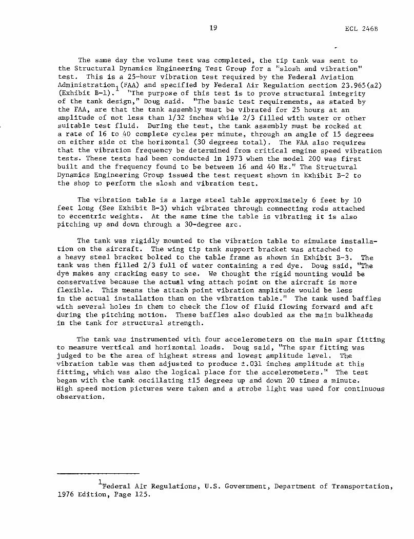
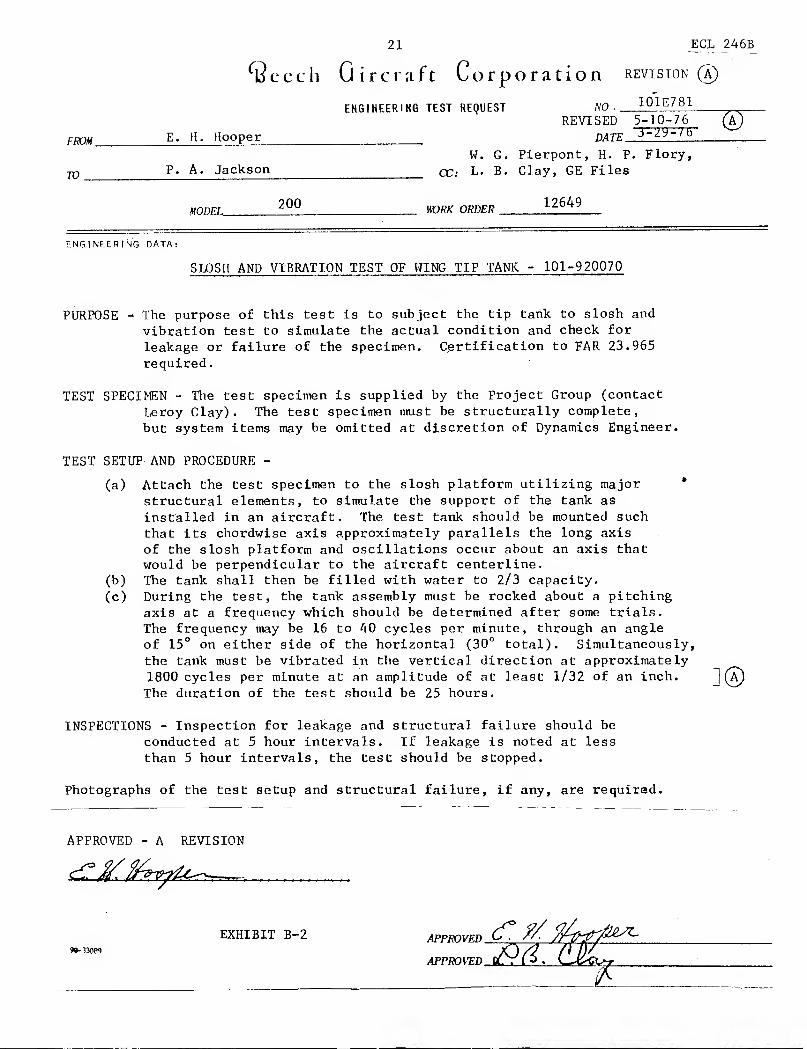
The same day the volume test was completed, the tip tank was sent tothe Structural Dynamics Engineering Test Group for a "slosh and vibration"test. This is a 25-hour vibration test required by the Federal AviationAdministration^ (FAA) and specified by Federal Air Regulation section 23.965(a2)(Exhibit B-l) . "The purpose of this test is to prove structural integrityof the tank design," Doug said. "The basic test requirements, as stated bythe FAA, are that the tank assembly must be vibrated for 25 hours at anamplitude of not less than 1/32 inches while 2/3 filled with water or othersuitable test fluid. During the test, the tank assembly must be rocked ata rate of 16 to 40 complete cycles per minute, through an angle of 15 degreeson either side ot the horizontal (30 degrees total) . The FAA also requiresthat the vibration frequency be determined from critical engine speed vibrationtests. These tests had been conducted in 1973 when the model 200 was firstbuilt and the frequency found to be between 16 and 40 Hz." The StructuralDynamics Engineering Group issued the test request shown in Exhibit B-2 tothe shop to perform the slosh and vibration test.
The vibration table is a large steel table approximately 6 feet by 10feet long (See Exhibit B-3) which vibrates through connecting rods attachedto eccentric weights. At the same time the table is vibrating it is alsopitching up and down through a 30-degree arc.
The tank was rigidly mounted to the vibration table to simulate installa-tion on the aircraft. The wing tip tank support bracket was attached toa heavy steel bracket bolted to the table frame as shown in Exhibit B-3. Thetank was then filled 2/3 full of water containing a red dye. Doug said, "Thedye makes any cracking easy to see. We thought the rigid mounting would beconservative because the actual wing attach point on the aircraft is moreflexible. This means the attach point vibration amplitude would be lessin the actual installation than on the vibration table." The tank used baffleswith several holes in them to check the flow of fluid flowing forward and aftduring the pitching motion. These baffles also doubled as the main bulkheadsin the tank for structural strength.
The tank was instrumented with four accelerometers on the main spar fittingto measure vertical and horizontal loads. Doug said, "The spar fitting wasjudged to be the area of highest stress and lowest amplitude level. Thevibration table was then adjusted to produce ±.031 inches amplitude at thisfitting, which was also the logical place for the accelerometers." The testbegan with the tank oscillating ±15 degrees up and down 20 times a minute.High speed motion pictures were taken and a strobe light was used for continuousobservation.
Federal Air Regulations, U.S. Government, Department of Transportation,1976 Edition, Page 125.

20
2-3.965
(2) except as noted below, the tankassembly must be vibrated for 25 hoursat an amplitude of not less than %2 ofan inch (unless another amplitude is
substantiated) while % filled with wateror other suitable test fluid.
(3) The test frequency of vibrationmust be as follows
:
(i) If no frequency of vibration re-sulting from any r.p.m. within the nor-mal operating range of engine speeds is
critical, the test frequency of vibration,in number of cycles per minute, must bethe number obtained by multiplying themaximum continuous engine speed(r.p.m.) by 0.9.
(ii) If only one frequency of vibrationresulting from any r.p.m. within the nor-mal operating range of engine speeds is
critical, that frequency of vibration mustbe the test frequency.
(iii) If more than one frequency ofvibration resulting from any r.p.m. with-in the normal operating range of enginespeeds is critical, the most critical ofthese frequencies must be the test fre-quency.
(4) Under subparagraph (3) (ii) and(iii) of this paragraph, the time of testmust be adjusted to accomplish the samenumber of vibration cycles that wouldbe accomplished in 25 hours at the fre-quency specified in subparagraph (3) (i)
of this paragraph.(5) During the test, the tank assem-
bly must be rocked at a rate of 16 to 20complete cycles per minute, through anangle of 15 degrees on either side of thehorizontal (30 degrees total), about anaxis parallel to the axis of the fuselage,
for 25 hours.
(c) Each integral tank using methodsof construction and sealing not previ-
ously proven to be adequate by test dataor service experience must be able to
withstand the vibration test specified in
subparagraphs (1) through (4) of para-graph <b)
.
(d) Each tank with a nonmotallicliner must be subjected to the sloshing
test outlined in subparagraph (5) of
paragraph <b) of this section, with the
fuel at room temperature. In addition,
a specimen liner of the same basic con-struction
, as that to be used in the air-
plane must, when installed in a suitable
test tank, withstand the sloshing test
with fuel at a temperature of 110° F.
>r;.\I.\L. l 'l ILiTV, A XI) ACROBATIC! ['ART 23
§ 23.967 Fuel tank installation.
(a) Each fuel tank must be supportedso that tank loads are not concentrated.In addition
—
(1) There must be pads, if necessary,to prevent chafing between each tankand its supports;
(2) Padding must be nonabsorbentor treated to prevent the absorption offuel;
(3) If a flexible tank liner is used, it
must be supported so that it is not re-quired to withstand fluid loads;
(4) Interior surfaces adjacent to theliner must be smooth and free from pro-jections that could . cause wear, unless
—
(i) Provisions are made for protectionof the liner at those points; or
(ii) The construction of the liner it-
self provides such protection; and(5) A positive pressure must be main-
tained within the vapor space of eachbladder cell under any condition of op-eration, including the critical conditionsof low air-speed and rate of descentlikely to be encountered.
(b) Each tank compartment must beventilated and drained to prevent theaccumulation of flammable fluids orvapors. Each compartment adjacent toa tank that is an integral part of theairplane structure must also be venti-lated and drained.
(c) No fuel tank may be on the engineside of the firewall. There must be atleast one-half inch of clearance betweenthe fuel tank and the firewall. No partof the engine nacelle skin that lies im-mediately behind a major air openingfrom the engine compartment may actas the wall of an integral tank.
(d) No fuel tank may be in the per-sonnel compartment of a multiengineairplane. If a fuel tank is in the per-sonnel compartment of a single engineairplane, it must
—
(1) If no larger than 25 gallons total
capacity, be properly drained and venti-lated; and
<2> If larger than 25 gallons totalcapacity
—
(i) (For a conventional fuel tank)be isolated from the personnel compart-ment by fume and fuel proof enclosures;or
(ii) (For a bladder type fuel cell)
have a retaining shell that is at leastequivalent to a metal fuel tank in struc-tural integrity and in fume and fuel
Exhibit B-l. Excerpts From Federal Aviation Regulations
21 ECL 246
B
^eech Gircraft Corporation revision®
ENGINEERING TEST REQUEST NO. 10lE781
REVI SED~
-10-76
FROM E. H. Hooper date
W. G. Pierpont, H. P. Flory,
m P. A. Jackson qq. l. B. Clay, GE Files
200 WRK ORDER 12649
ENGINEERING DATA:
SLOSH AND VIBRATION TEST OF WING TIP TANK - 101-920070
PURPOSE - The purpose of this test is to subject the tip tank to slosh and
vibration test to simulate the actual condition and check for
leakage or failure of the specimen. Certification to FAR 23.965
required
.
TEST SPECIMEN - The test specimen is supplied by the Project Group (contact
Leroy Clay). The test specimen must be structurally complete,
but system items may be omitted at discretion of Dynamics Engineer.
TEST SETUP AND PROCEDURE -
(a) Attach the test specimen to the slosh platform utilizing major *
structural elements, to simulate the support of the tank as
installed in an aircraft. The test tank should be mounted such
that its chordwise axis approximately parallels the long axis
of the slosh platform and oscillations occur about an axis thatwould be perpendicular to the aircraft centerline.
(b) The tank shall then be filled with water to 2/3 capacity.
(c) During the test, the tank assembly must be rocked about a pitchingaxis at a frequency which should be determined after some trials.
The frequency may be 16 to 40 cycles per minute, through an angle
of 15° on either side of the horizontal (30° total). Simultaneously,the tank must be vibrated in the vertical direction at approximately1800 cycles per minute at an amplitude of at least 1/32 of an inch. ~j (A
The duration of the test should be 25 hours.
INSPECTIONS - Inspection for leakage and structural failure should be
conducted at 5 hour intervals. If leakage is noted at less
than 5 hour intervals, the test should be stopped.
Photographs of the test setup and structural failure, if any, are required.
APPROVED - A REVISION
EXHIBIT B-2 APPROVED


23 ECL 246B
After a little more than 2 hours of this test, the tank cracked in theweld area where the spar fitting went through the skin of the tank into thetank bulkhead. Also, the aft bulkhead attached to the rear stabilizer crackedat a hole in the bulkhead (Exhibits B-4 &-4A ). Doug said, "We felt we eitherhad stresses higher than anticipated from the structural and dynamic loadanalyses or else the stresses produced in the test were at places we did notexpect them to be."
A meeting was called between the Propulsion Systems Group, the StructuralTest Group and the Project Engineering Group to discuss the possible causesof the tip tank's failure. Doug recalled, "We all agreed that the imposedstresses from bending were designed to flow from the bulkhead ring into themain spar fitting and into the wing. The tank had been designed with aweld around this fitting at the tank skin to seal it fuel tight. We decidedthat this weld was short circuiting the stress flow and causing the stressesto concentrate at the intersection of the spar fitting and skin. We alsothought the single aft bulkhead was receiving an excessive amount of vibrationdue to the rigid mounting to the vibration table. We reviewed the calculationsfor the stresses and rechecked the standard safety margins which had beendesigned into the tank. We decided to provide an even larger safety marginstructurally in this area to eliminate any reoccurrence of cracking."
A new tip tank was then built with the weld around the main spar fittingremoved and replaced with a flexible sealant. Also, the single .040 thickbulkhead was replaced with two .061 bulkheads placed back-to-back on eitherside of the spar fitting.
Five weeks later the new tip tank (Design #2) was mounted on the vibrationtable just as before and the test began with zero time on the tank. The Beechengineers were optimistic that this test would prove out their theory of
stress concentration in the weld as the cause of the first failure. Butthis time, a problem developed in a different area. The aft stabilizer mountfractured at a point 3 inches from the attach point (See Exhibit B-5) to
the vibration table. Doug said, "it now seemed apparent that the stress levelspresent were much higher than had been expected. We thought the test procedureshould be examined for accuracy and more realistic simulation of the actualinstallation.
"
The aft stabilizer mount was repaired with a splice plate and the waterwas replaced with jet fuel having less weight. The fuel volume was decreasedfrom 39 gallons to 35 gallons due to an error in interpreting the tank'stotal volume. The test personnel originally thought the liquid capacity ofthe tank was 58 gallons; however, the liquid capacity was never more than 53gallons. Doug said, "The total volume of the tank; liquid and expansionair space was indeed 58 gallons. This change produced an 86 pound reductionin the total tank weight."


25 ECL 246B
EXHIBIT B-4A

26 ECL 246B
AFT STABILIZER MOUNT
EXHIBIT B-5

27 ECL 246B
"The FAA was contacted by telephone and asked to come out and inspectour test equipment and procedures," Doug continued. Specifically, Beechwanted to know if the test was too severe. An FAA test engineer examinedthe test setup and advised Beech that we had erred in interpreting the FAAtest requirements. The requirement of a vibration amplitude of .031 inch wasnot at the point of minimum amplitude, but was an average amplitude alongthe length of the tank. We were all a little upset that the regulation hadnot spelled this out."
Therefore, amplitude readings were taken using accelerometers at elevenlocations along the length of the tank and averaged together. The vibrationlevel was adjusted until the average was ±.031 inches or greater and test #3
was started.
Test #3 was also short lived, lasting only 7 hours before the nose weightsupport boss cracked the forward bulkhead at a weld joint (Exhibit B-6). Thefunction of the nose weight was to provide stability against pitching inflight when the tank was empty. (Later in the program the weight was foundnot to be necessary and was removed.) This bracket was screwed to the wallsof the tank rather than welded (see Exhibit B-7) . This provided a littlemore flexing in the mounting bracketry and was the easiest means of reworkingthe existing tank. This configuration began test #4.
Test #4 ran for 1.5 hours until a crack in the skin was found atthe main spar bracket on the lower side (see Exhibit B-8) . "The crack wasunder the sealant which was added during test #2," Doug said, "and hadprobably been growing undetected. We quickly designed a heavy skin doublerfrom .080 thick 2024-T4 aluminum sheet and installed it around the main sparfitting using .12 inch diameter rivets. Sealant was used between the doublerand the tank skin to prevent leaks around the rivets. This became test #5and proved to be the final design configuration. The test was continued for25 hours and 16 minutes, giving a total time on the tank of slightly lessthan 34 hours. The tank was declared a success, as it had exceeded the minimumFAA test requirements (25 hours) by almost 9 hours.
The final structural test for the tip tank was an ultimate pressure test."This test is designed to determine the tip tank's structural integrity underinternal pressure," Doug related. The tip tank was sealed off and pressurizedwith nitrogen from a high pressure bottle. The pressure was increased to 12.3psig and held there for one minute to check for leaks. The pressure was thenincreased to 15.0 psig and held for two minutes.
Doug said, "The tank was 15 inches in diameter with an .080 inch wall,so this gave a stress of about 1400 psi. The tank skin was 6061-T42 aluminum,which has a yield strength of 19,000 psi. This provided a big safety factorbut the .080 inch skin thickness was dictated by lightning protection require-ments, not structural requirements." No leaks were detected and the test wasterminated. A thorough examination was made of the tank to determine if
any permanent deformation of the tank walls had occurred, however none was found.

28 ECL 246B
FUEL CJKMIT^
v
STEEL Vo£lktfT
SUPfOtT POL MOUWHUG10 VvJEtGUT
FVAJE) ^ECQOKl OF TIP TAM \C

F\JUO SECTION! OF TIP TMvJVC

30
ECL 246B

ECL 246B
The next test scheduled for the tip tank was the actual flight test to
determine if fuel would feed from the tank and also to check the operation of
the fuel vent system. The tanks and their associated plumbing and wiringwere installed on a test aircraft which had a modified wing to accommodate itsinstallation. The left tip tank and wing were filled with fuel and found to
hold 325 gallons. The right hand tip tank and wing held the same amount.Doug said, "These quantities indicated the tip tank held 53 gallons (determinedfrom the first volume test) plus 2 additional gallons per side which werepicked up from filling the plumbing lines and expansion spaces in the wingitself. The total fuel system expansion space was now located in the tiptank."
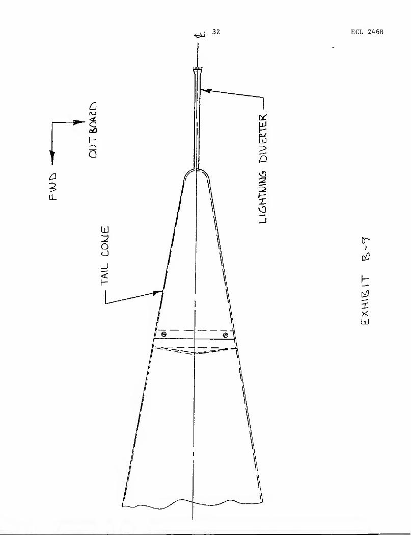
The first flight test had several surprises for Doug; one of them totallyunexpected. "Soon after takeoff, the pilot noticed the left lightning diverterlocated on the extreme trailing end of the tip tank was missing (Exhibit B-9).A quick look at the right hand tip tank showed no lightning diverter thereeither. The pilot and I agreed that the lightning diver ters had been in placebefore takeoff. We landed, and I examined the mounting bracket for thelightning diverter. The metal base of the diverter was still attached to thetip tank but the non*-metallic shaft was missing. Something must have brokenboth diverters off at the base soon after takeoff. Since no one observed thisincident, two new diverters were installed and another flight was scheduled.This time two people were assigned to watch both diverters continuouslyduring takeoff and flight." Soon after takeoff, both diverters began tovibrate, causing a blurred cone-shaped appearance until they fatigued at thebase and broke away from the aircraft. "It wasn't too difficult to see thata vortex air flow off the tip tank had made the diverters oscillate about theaxis of the tank," Doug continued. "In other words, the symmetry of the diverterinstallation was causing the diverter to follow the air flow in a spiral pathuntil it broke from fatigue.
"The solution to this problem seemed to be to eliminate the symmetry ofthe installation. If the diverter was moved out of the center of the vortexair flow, then continuous circular motion should cease. Therefore, we
oangled the mounting of the diverter base attach point 25 outward (Exhibit B-9A)and this configuration was test flown. The 25 angle was arbitrary and couldhave been changed if required. The diverters were carefully observed throughoutthe next flight and no oscillatory motion was observed. The lightningdiverters presented no further problems."
With this problem solved, the next test was to check out the fuel ventsystem. This test consisted of putting the aircraft through various flightmaneuvers to make sure fuel would feed into the wing. The FAA requirementsstate, "A positive pressure must be maintained withjn the vapor space of each(fuel tank) under any condition of operation ..." The tip tank was instru-mented with small plastic hoses which were connected to pressure gauges inthe aircraft cabin. Doug said, "The pilot put the plane into a series of sideslips and the air pressure above the fuel in the tank remained positive.
Federal Air Regulations, U.S. Government, Department of Transportation,1976 Edition, Paragraph 23.967(a)


34 ECL 246B
However, we could see a continuous stream of fuel pouring from the fuel ventunder the wing. We landed and I disassembled the vent lines leading intothe tip tank. I thought maybe a pressure relief valve was opening prematurelydue to the fuel surging back and forth. However, the valve was working okay.Next we measured the fuel surge pressure using pressure transducers and foundit to be below the valve's release point. At this point we decided to takeanother hard look at the original vent system design. Originally, when I
designed the tip tank fuel system, it had seemed necessary to interconnect thevent line between the tip tank and the wing tank in order for the air pressurein the tanks to remain equal. I now went back and studied the system layoutin detail, making a fuel system schematic of the tip tank area. A schematicis a diagram of how all the plumbing is interconnected, and can be useful introubleshooting system problems (see Exhibit B-10) . I found that the tip
tank vent line interconnected with the overboard vent line through a commonvent chamber. This allowed an open path for the fuel to flow overboard whenthe wings were not level. Looking at the fuel system schematic, it was obviousthat the solution to the fuel dumping problem was to isolate the two ventlines. Schematics are very good in understanding how a system operates asopposed to how it's put together. The usual engineering drawing gives allthe details of how to put a system together including part numbers, assemblyinstruction, etc. This makes it somewhat difficult to see what's reallyhappening within the system itself." The two fuel lines were isolated throughrerouting of the plumbing. The system was checked on the next flight andand no fuel dumping occurred throughout the remainder of the test program.
The final test to be performed on the tip tank was a lightning striketest. The purpose of this test was to insure that if the tip tank was hitby lightning, no damage of any consequence would occur. Doug said, "We knowfrom experience that an aircraft's wing tips are a favorite location forlightning strikes, therefore precautions were taken to protect that area.
We hired General Electric Company to perform the test because Beech does nothave the facilities to do so. We shipped them the entire aircraft wing withthe tip tank installed on it."
Doug said the plexiglas nose cone was shielded by three very thin aluminumstrips glued to the outer surface (Exhibit B-ll) . These strips were designedto vaporize when hit by lightning and the strip would provide an ionized airpath to the rear edge of the nose cone where it would transfer to the aluminumaircraft skin. Doug stated, "This all sounded good in theory, but now wewere about to see if it really worked. In the last 10 years, much researchhas been done in the area of determining the voltage and current found inlightning. It has been found that nearly all lightning strikes have voltagesless than 150,000 VDC and the current is less than 200,000 amps. Therefore,these two values were used as the test criteria as recommended in FAA docu-mentation reports and by the Society of Automotive Engineers."


J

37ECL 246B
"The lightning test set-up was very impressive," Doug said. "Our testwing with the tip tank installed was mounted horizontally in a large testcell at General Electric. The wing was electrically joined to the groundor negative side of a very large DC current surge generator (ExhibitB-12) . A long movable arm with the positive probe attached was positionedwithin 12 inches of the portion of the tank being tested. This probe wasconnected to a large bank of capacitors where the charge was built upand then discharged at the proper time.
"The nose cone was the first to be tested," Doug said, "and it passed thetest beautifully. The strips of aluminum vaporized and discharged into theaircraft skin." Then the test engineer at General Electric asked, "Whathappens if the aluminum foil is removed?" There was one way to find out andthis test had surprising results. The plexiglas took the lightning strikewithout any damage. Doug said, "Plexiglas is one of the strongest plasticsin use and was able to transfer the electrical charge along its outer surfaceinto the aluminum skin. To show that the one test was not an accident,the test was repeated four more times until the nose cone finally split. Weweren't too concerned after the fourth strike since five lightning strikesto the same nose cone are highly improbable."
Similar tests were performed on the lightning diverter mounted on thetrailing end of the tank. Again there was no damage to the tank; howeverthe lightning diverters were damaged on the third strike. Doug said, "Wheneveran aircraft crew suspects they were hit by lightning, it is a general practiceto make a thorough examination of the exterior of the aircraft after landingto look for damage. The diverters are easily removed and replaced and arerelatively inexpensive. The probability of an aircraft getting hit by lightningthree times in the same place on the same flight is extremely remote."
The last lightning test was performed by striking an access cover on topof the tank. Doug said, "It had already been proven by previous testsseveral years ago that aluminum .080 inches thick would not be penetratedby lightning. However, in this case we had a cover plate with a non-conductiverubber gasket under it. This proved to be a poor conductive path for thelightning to take." General Electric engineers mounted a camera inside thetank with the lens open. "When the lightning hit the cover plate," Dougrecalled, "the camera recorded a small flash of light. This told us thatwe had poor conduction between the cover plate and a metal bracket insidewhich supported a fuel vent tube. The current was jumping from the coverthrough the rubber gasket to the metal bracket." General Electric suggestedBeech make the bracket from a non-conductive material such as plastic so thecurrent would not arc across to it. Therefore a new bracket was made inexactly the same shape but the material was changed from aluminum to plastic.

38
TipTank
6yF @ 150kVor
54yF @ 50kV
rI
OSurgeGenerator
Wing ShieldedRoom

39 ECL 246B
This last test also produced some unexpected results in the tip tankelectrical wiring. Doug recalled, "When the lightning strike hit the tank,it immediately attempted to dissipate the current into the two spars andthree fuel lines . The electrical wires for the navigation lights and strobelights in the tip tank were positioned parallel to the spars and fuel lines.As the current flowed in the spars and fuel lines, it set up a magnetic fieldwhich the wires cut through. The magnetic field induced a voltage in thewiring which was on the order of 1853 volts compared to the normal 28 voltsin the circuit. We felt this was too high to tolerate." The electricalengineers at Beech decided to shield the wiring with a metal conduit whichwas fabricated from aluminum tubing.
Both the plastic tube support bracket and the electrical conduit wereshipped to General Electric for final testing. Doug said, "We were confidentthese two changes would solve our problem but it was important to retest andverify the design." The test was conducted and the new designs proved to
be the solution to both lightning strike problems.
This was the conclusion to the design and testing stage of building thewing tip tanks for the Model 200 aircraft. The last job was to complete anyfinal FAA certification data which had not been previously submitted. Dougstated, "We maintain a FAA Certification file at Beech which is a completelisting of all changes and modifications to our aircraft. The file is physicallylocated at Beech but has the same meaning as if it were located in the officesof the FAA at Mid-Continent Airport in Wichita. We write letters to the fileand give a complete breakdown on how we complied with each applicable FAArequirement. These requirements were discussed and agreed upon at the verybeginning of the program. No program of this magnitude can be initiated untilall the rules of the game are first decided on.''
"In retrospect," Doug continued, "this program was a good example of howmost of our engineering jobs at Beech are conducted. If the job is much larger,such as designing, building and certifying an entirely new airplane, the programis more complex and more people are involved. But you still take the samebasic steps, namely:
1. Customer/ Beech provides design criteria to meet2. Proposed solution (s) are presented3. Negotiated solution is selected4. FAA certification rules are formally agreed upon5. Prototype part is built6. Prototype part is tested and evaluated7. Prototype part construction and test results are documented and
FAA certified8. Production parts are built
All these steps are necessary but do not always occur in the order shown. Manytimes production parts start while testing is going on to save time."

40 ECL 246B
Doug said he felt this particular job gave him insight into the workingsof the whole company because he saw the program beginning at a very earlystage. "I have a friend in the Marketing Department," Doug recalled, "whokept me informed on how this program was advancing in the early stages longbefore the full Engineering Department would normally be involved. It wasexciting to see an idea grow into a full fledged program and actually design,build and test the idea. For me, real engineering is being involved in thecomplete cycle from idea to hardware. The only link missing at this time isfeedback from the field telling me how well the system is functioning. Butthat will come with time and when it does, it will be a continuation of whathas already been learned."
"I learned several things on this project," Doug continued. "First, thevendor coordination with Globe Engineering was new to me in that I went to
their facilities to coordinate on production of the tanks. I work with ourshop all the time, but an outside production shop provided me with new insightinto the workings of our own Quality Control Department, Several times I wascalled upon to help solve problems in reworking tanks rejected by our QualityControl Department. This was necessary in order to maintain delivery of partson schedule. I was able to see the many inspection steps and procedures requiredbefore a piece of equipment is judged satisfactory for use on our aircraft."
Doug and Gene both became more involved directly in the testing of thetip tanks than in previous programs. This was the first time either of themhad monitored a test so closely. This turned out to be important because whenthe different failures in the tank occurred, they had first hand knowledgeof what actually happened, "I was particularly interested in the analysis ofeach failure," Doug stated. "To look at the failed parts and try to reconstructin your mind the events leading up to the failure was a real challenge. Butmost of all, the failure analysis provided knowledge to be used in the designof future hardware,"
The third area of the program which provided new design experience wasin the design and testing for lightning protection. "My knowledge of lightningphenomena was very limited before this program started," Doug related. "Theseveral days research I did in the Beech Library taught me a lot aboutconditions which create lightning, how it strikes, the energy levels in anaverage strike and how to protect aircraft structures from damage. The infor-mation I learned was applicable anywhere on an airplane and not just on tip tanks.Doug was particularly impressed by lightning tests at General Electric."Obviously you can't just sit around waiting for a rainy day to run a lightningtest," Doug said. "You have to be able to make your own lightning and, mostof all, control it! Watching the test and seeing the results builds plenty ofrespect for the energy released by lightning."
Doug also pointed out that the process of writing the case study wasbeneficial. "It has given me the opportunity to look back at one particularprogram in detail and examine the events one by one. This is the first timeI have had the opportunity to study each of the steps in the design processand think about what was learned during each phase. In the day-to-day routinejob you run into a problem, overcome it, and go on to the next problem, usuallywith not much thought as to what was learned."

41 ECL 246B
"I also believe this report has helped me to better understand how BeechAircraft is organized and how it functions. Until now I had a rather narrowview of how programs were put together and carried to completion. This reportgave me better insight into how many departments work together. I beganto see that Engineering was the middle link in the chain with the Sales andMarketing Department at the front and Manufacturing at the end. All threeunits are required to complete a given task."
42 ECL 246N
Instructors Note
for
Tip Tanks for the Beech
Super King Air
This case study was written for undergraduate students majoring in
Engineering. It is intended to provide the student with insight into how
a sample project begins, how the design develops and, finally, how the
hardware and system is tested. This case study examines the structure of an
Engineering Department within a typical aircraft company. Organization of
the particular project is discussed and areas of responsibility are pointed out
to the student. The design procedures in one particular project group
are followed from start to finish. Specific examples of engineering decisions
are presented showing that no clear-cut answer is available in most cases.
Trade-offs in optimum performance must be made to obtain a product acceptable
to everyone concerned.
A section of this case study is devoted to an engineering job not
usually discussed in the typical engineering curriculum: determining the
cost of the project. The case study example looks at the engineer's job of
determining how much the project will cost before it is started, A sample
job breakdown is provided with the hours bid to do the described job left
blank. This could provide a possible problem for the student to attempt.
The actual hours bid for the example project are shown on the next page.
The second part of the case study deals with the hardware and system
testing that were performed on the finished product. Details of unanticipated
problems are given and how solutions are found. The student can see that
engineering design projects rarely run smoothly and problems should be
expected to occur.

43Model 200 52-Galloi: lip Tank Job Bid
ECL 246N
.Percent of TotalTask *
Hours
1. Design a separate wing tip tank fuel systeminstallation drawing (2 J-size sheets) . Drawing shallshow all fuel and vent- lines up to but not includingequipment installation on end of integral fuel tank.Drawing shall show installation of flapper valves, drainvalves, anti-siphon valve and electrical connector forfuel quantity probes.
m.4^0
a. Design an access plate for fuel vents andelectrical plug to pass through wall of tank.(One D-size drawing)
2. Add a tabulation to 101-920000 to allow incorporationof tank assembly into main fuel system. (One E-sizelayout and two C.O.'s - change order)
6.6
a. Design adapter plate for outboard end of integral tank. 2.S
b. Create new fuel gauging drawing to add new fuelquantity probes to tip tank. One CO. and D-sizelayout
.
3. Calibrate tip tank fuel quantity indicating system.
4. Engineering coordination with:
a. Globe Engineeringb. Project Groupc. Electrical Engineering Groupd. Rochester Gauges, Inc.e. Experimental Shop (Fabrication and installation of
plumbing and hardware)f. Flight Test Groupg. Publications (Flight Manual and Maintenance Manual)h. General Electric for lightning test.
/O.OZ.--7
t-(j>
5.04-4
4-45. Supervision. t-L-1
6. Design of the tip tank structure. This includes fuelplumbing, navigation lights installation, mounting bracketsand lightning protection for the tank. Project Group willdesign tank fairings. 5 E-size drawings.
n.%
7. Interpretation and analysis of ground and flight test data. -7 -7
8. Preparation of FAA certification letters and documents.. 3.3
Total /oo-o*Actual hours deleted at company request.