ecotran system - crane pumps
TRANSCRIPT

A Crane Co. Company
STATION INSTALLATION & OPERATION MANUAL
IMPORTANT! Read all instructions in this manual before operating pump. As a result of Crane Pumps & Systems, Inc., constant product improvement program, product changes may occur. As such Crane Pumps & Systems reserves the right to changeproductwithoutpriorwrittennotification.
420 Third Street 83 West Drive, BramtonPiqua, Ohio 45356 Ontario, Canada L6T 2J6Phone: (937) 778-8947 Phone: (905) 457-6223Fax: (937) 773-7157 Fax: (905) 457-2650www.cranepumps.com Form No. 119061A-Rev. R
EcoTRAN System
*Optional Rock Cover and ESPS Shown
2
Other brand and product names are trademarks or registered trademarks of their respective holders.® Barnes is a registered trademark of Crane Pumps & Systems, Inc© Crane Pumps & Systems, Inc. 6/05, 7/05, 1/06, 5/06, 7/06, 9/06, 10/06, 2/07 Alteration Rights Reserved
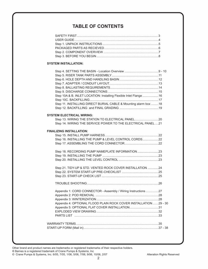
TABLE OF CONTENTS SAFETY FIRST ............................................................................................... 3 USER GUIDE ...................................................................................................4 Step 1. UNPACK INSTRUCTIONS ..................................................................5 PACKAGED PARTS AS RECIEVED ................................................................6 Step 2. COMPONENT OVERVIEW .................................................................7 Step 3. BEFORE YOU BEGIN .........................................................................8 SYSTEM INSTALLATION:
Step 4. SETTING THE BASIN - Location Overview ........................................9 - 10 Step 5. RISER TANK PARTS ASSEMBLY .......................................................11 Step 6. HOLE DEPTH AND HANDLING BASIN ..............................................12 Step 7. ADAPTER / CONDUIT LAYOUT ..........................................................13 Step 8. BALLASTING REQUIREMENTS .........................................................14 Step 9. DISCHARGE CONNECTIONS ............................................................15 Step 10A & B. INLET LOCATION: Installing Flexible Inlet Flange ...................16 Step 10C. BACKFILLING .................................................................................17 Step 11. INSTALLING DIRECT BURIAL CABLE & Mounting alarm box .........18 Step 12. BACKFILLING and FINAL GRADING ..............................................19
SYSTEM ELECTRICAL WIRING: Step 13. WIRING THE STATION TO ELECTRICAL PANEL ............................20 Step 14. WIRING THE SERVICE POWER TO THE ELECTRICAL PANEL ....21
FINALIZING INSTALLATION: Step 15. INSTALL PUMP HARNESS ...............................................................22 Step 16. INSTALLING THE PUMP & LEVEL CONTROL CORDS ...................22 Step 17. ASSEMBLING THE CORD CONNECTOR ........................................22
Step 18. RECORDING PUMP NAMEPLATE INFORMATION .........................23 Step 19. INSTALLING THE PUMP ..................................................................23 Step 20. INSTALLING THE LEVEL CONTROL ...............................................23
Step 21. TIDY-UP & STD. VENTED ROCK COVER INSTALLATION .............24 Step 22. SYSTEM START-UP PRE-CHECKLIST ...........................................25 Step 23. START-UP CHECK LIST ...................................................................25 TROUBLE SHOOTING ....................................................................................26
Appendix 1: CORD CONNECTOR - Assembly / Wiring Instructions ...............27 Appendix 2: POD REMOVAL ..........................................................................28 Appendix 3: WINTERIZATION .........................................................................28 Appendix 4: OPTIONAL FLOOD PLAIN ROCK COVER INSTALLATION .......29 - 30 Appendix 5: OPTIONAL FLAT COVER INSTALLATION ..................................31 EXPLODED VIEW DRAWING .........................................................................32 PARTS LIST ...................................................................................................33
WARRANTY TERMS .................................................................................................35 START-UP FORM (Mail in) ........................................................................................37 - 38
3
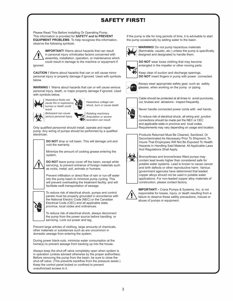
Please Read This Before Installing Or Operating Pump. This information is provided for SAFETY and to PREVENT EQUIPMENT PROBLEMS. To help recognize this information, observe the following symbols:
IMPORTANT! Warns about hazards that can result in personal injury orIndicates factors concerned with assembly, installation, operation, or maintenance which could result in damage to the machine or equipment if
ignored.
CAUTION ! Warns about hazards that can or will cause minor personal injury or property damage if ignored. Used with symbols below.
WARNING ! Warns about hazards that can or will cause serious personal injury, death, or major property damage if ignored. Used with symbols below.
Only qualified personnel should install, operate and repair pump. Any wiring of pumps should be performed by a qualified electrician.
DO NOT drop or roll basin. This will damage unit and void the warranty.
Minimize the amount of cooking grease entering the system.
DO NOT leave pump cover off the basin, except while servicing, to prevent entrance of foreign materials such as rocks, metal, soil, animals or humans.
Prevent infiltration or direct flow of rain or run-off water into the pump basin to minimize pump cycling. This will prevent overloading the treatment facility, and will facilitate swift transportation of sewage.
To reduce risk of electrical shock, pumps and control panels must be properly grounded in accordance with the National Electric Code (NEC) or the Canadian Electrical Code (CEC) and all applicable state, province, local codes and ordinances.
To reduce risk of electrical shock, always disconnect the pump from the power source before handling or servicing. Lock out power and tag.
Prevent large articles of clothing, large amounts of chemicals, other materials or substances such as are uncommon in domestic sewage from entering the system.
During power black-outs, minimize water consumption at the home(s) to prevent sewage from backing up into the house.
Always keep the shut-off valve completely open when system is in operation (unless advised otherwise by the proper authorities). Before removing the pump from the basin, be sure to close the shut-off valve. (This prevents backflow from the pressure sewer.)Keep the control panel locked or confined to prevent unauthorized access to it.
If the pump is idle for long periods of time, it is advisable to start the pump occasionally by adding water to the basin.
WARNING! Do not pump hazardous materials (flammable, caustic, etc.) unless the pump is specifically designed and designated to handle them.
DO NOT wear loose clothing that may become entangled in the impeller or other moving parts.
Keep clear of suction and discharge openings. DO NOT insert fingers in pump with power connected.
Always wear appropriate safety gear, such as safety glasses, when working on the pump or piping.
Cable should be protected at all times to avoid punctures, cut, bruises and abrasions - inspect frequently.
Never handle connected power cords with wet hands.
To reduce risk of electrical shock, all wiring and junction connections should be made per the NEC or CEC and applicable state or province and local codes. Requirements may vary depending on usage and location.
Products Returned Must Be Cleaned, Sanitized, Or Decontaminated As Necessary Prior To Shipment, To Insure That Employees Will Not Be Exposed To Health Hazards In Handling Said Material. All Applicable Laws And Regulations Shall Apply. Bronze/brass and bronze/brass fitted pumps may contain lead levels higher than considered safe for potable water systems. Lead is known to cause cancer and birth defects or other reproductive harm. Various government agencies have determined that leaded copper alloys should not be used in potable water applications. For non-leaded copper alloy materials of construction, please contact factory.
IMPORTANT! - Crane Pumps & Systems, Inc. is not responsible for losses, injury, or death resulting from a failure to observe these safety precautions, misuse or abuse of pumps or equipment.
SAFETY FIRST!
Hazardous fluids can cause fire or explosions, burnes or death could result.Biohazard can cause serious personal injury.
Rotating machineryAmputation or severe laceration can result.
Hazardous voltage can shock, burn or cause death.
4
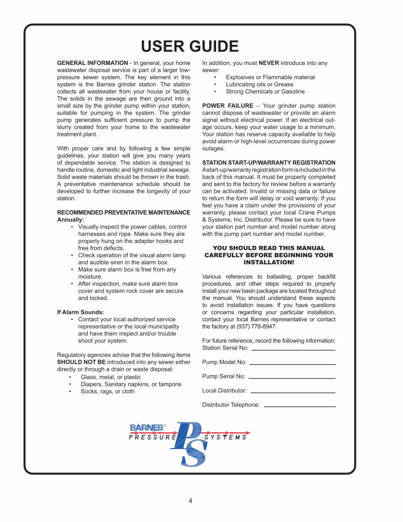
GENERAL INFORMATION - In general, your home wastewater disposal service is part of a larger low-pressure sewer system. The key element in this system is the Barnes grinder station. The station collects all wastewater from your house or facility. The solids in the sewage are then ground into a small size by the grinder pump within your station, suitable for pumping in the system. The grinder pump generates sufficient pressure to pump the slurry created from your home to the wastewater treatment plant.
With proper care and by following a few simple guidelines, your station will give you many years of dependable service. The station is designed to handle routine, domestic and light industrial sewage. Solid waste materials should be thrown in the trash. A preventative maintenance schedule should be developed to further increase the longevity of your station.
RECOMMENDED PREVENTATIVE MAINTENANCE Annually: • Visually inspect the power cables, control harnesses and rope. Make sure they are properly hung on the adapter hooks and free from defects. • Check operation of the visual alarm lamp and audible siren in the alarm box • Make sure alarm box is free from any moisture. • After inspection, make sure alarm box cover and system rock cover are secure and locked.
If Alarm Sounds: • Contact your local authorized service representative or the local municipality and have them inspect and/or trouble shoot your system.
Regulatory agencies advise that the following items SHOULD NOT BE introduced into any sewer either directly or through a drain or waste disposal:
• Glass, metal, or plastic• Diapers, Sanitary napkins, or tampons• Socks, rags, or cloth
In addition, you must NEVER introduce into any sewer:
• Explosives or Flammable material• Lubricating oils or Grease• Strong Chemicals or Gasoline
POWER FAILURE – Your grinder pump station cannot dispose of wastewater or provide an alarm signal without electrical power. If an electrical out-age occurs, keep your water usage to a minimum. Your station has reserve capacity available to help avoid alarm or high-level occurrences during power outages.
STATION START-UP/WARRANTY REGISTRATION A start-up/warranty registration form is included in the back of this manual. It must be properly completed and sent to the factory for review before a warranty can be activated. Invalid or missing data or failure to return the form will delay or void warranty. If you feel you have a claim under the provisions of your warranty, please contact your local Crane Pumps & Systems, Inc. Distributor. Please be sure to have your station part number and model number along with the pump part number and model number.
YOU SHOULD READ THIS MANUAL CAREFULLY BEFORE BEGINNING YOUR
INSTALLATION!
Various references to ballasting, proper backfill procedures, and other steps required to properly install your new basin package are located throughout the manual. You should understand these aspects to avoid installation issues. If you have questions or concerns regarding your particular installation, contact your local Barnes representative or contact the factory at (937) 778-8947.
For future reference, record the following information:Station Serial No:
Pump Model No:
Pump Serial No:
Local Distributor:
Distributor Telephone:
USER GUIDE

5
STEP 1: UNPACK INSTRUCTION
Received EcoTRAN Package
STEP 1: Cut the banding and discard. STEP 2: Roll the tank to its right side up position and remove the level control.
STEP 3: Open the “PARTS BOX” and remove enclosed contents.
STEP 4: Open the pump box and remove the enclosed pump.
*NOTE: Optional rock cover shown.

6
PACKAGED PARTS AS RECEIVED
7
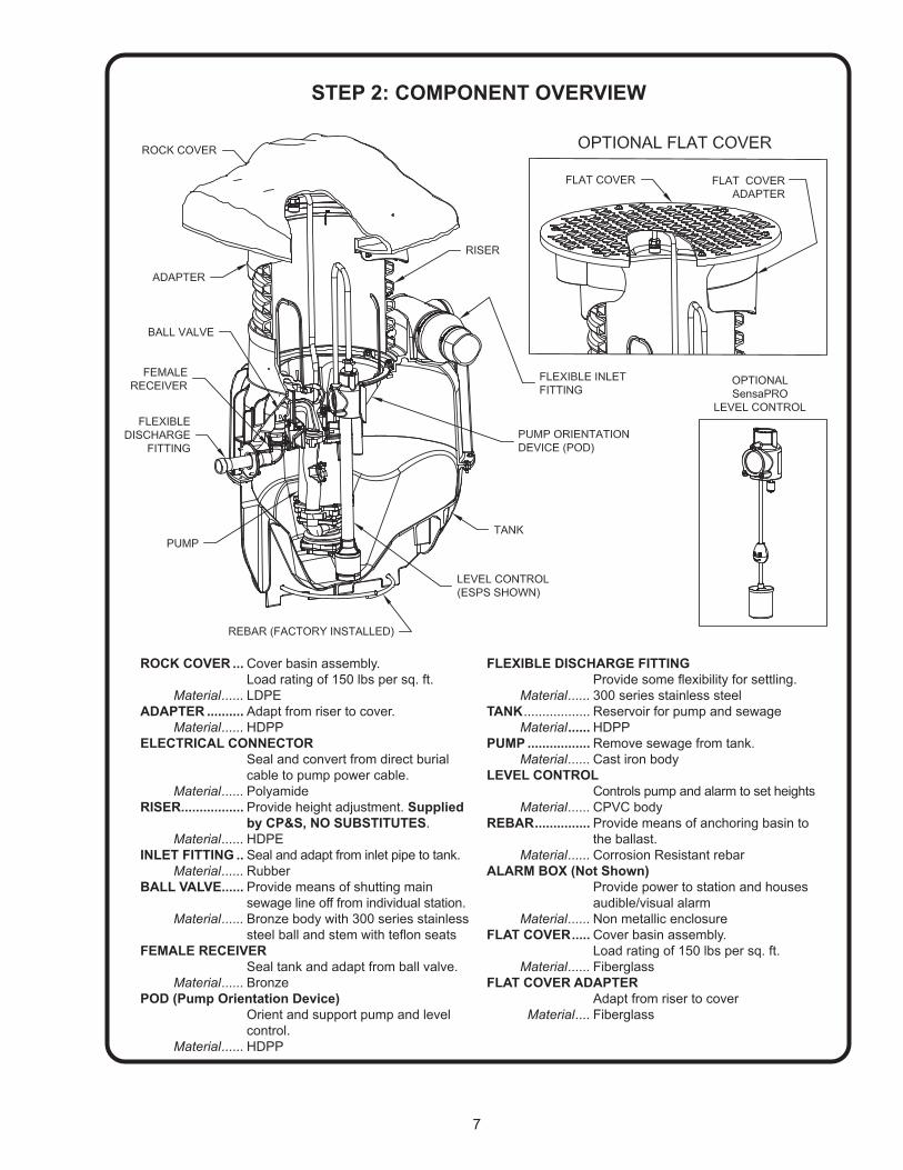
ROCK COVER ... Cover basin assembly. Load rating of 150 lbs per sq. ft. Material ...... LDPEADAPTER .......... Adapt from riser to cover. Material ...... HDPPELECTRICAL CONNECTOR Seal and convert from direct burial cable to pump power cable. Material ...... PolyamideRISER................. Provide height adjustment. Supplied by CP&S, NO SUBSTITUTES. Material ...... HDPEINLET FITTING .. Seal and adapt from inlet pipe to tank. Material ...... RubberBALL VALVE ...... Provide means of shutting main sewage line off from individual station. Material ...... Bronze body with 300 series stainless steel ball and stem with teflon seatsFEMALE RECEIVER Seal tank and adapt from ball valve. Material ...... BronzePOD (Pump Orientation Device) Orient and support pump and level control. Material ...... HDPP
FLEXIBLE DISCHARGE FITTING Provide some flexibility for settling. Material ...... 300 series stainless steelTANK .................. Reservoir for pump and sewage Material ...... HDPPPUMP ................. Remove sewage from tank. Material ...... Cast iron bodyLEVEL CONTROL Controls pump and alarm to set heights Material ...... CPVC bodyREBAR ............... Provide means of anchoring basin to the ballast. Material ...... Corrosion Resistant rebarALARM BOX (Not Shown) Provide power to station and houses audible/visual alarm Material ...... Non metallic enclosureFLAT COVER ..... Cover basin assembly. Load rating of 150 lbs per sq. ft. Material ...... FiberglassFLAT COVER ADAPTER Adapt from riser to cover Material .... Fiberglass
STEP 2: COMPONENT OVERVIEW

8
STEP 3: BEFORE YOU BEGIN• Read This Manual Completely Before Starting Your Installation.
• Consult local officials for any applicable codes and regulations. Obtain all necessary permits. Call your local utilities committee before digging to locate all underground lines and cables (page 9).
• Determine the best location for your basin and alarm panel (page 10).
• DO NOT drop or roll basin. This will damage unit and void the warranty.
• When determining the depth of the station, insure a minimum 1/8” per foot drop on the inlet line between the dwelling and pump station (pages 16-17). Minimize the use of elbows on the inlet line. If required only use 45° elbows.
• Determine where the incoming power will be supplied from and that it is properly rated for your station.
• Use only the electric cable specified. (page 18) DO NOT USE ANY OTHER CABLE. Substitutions may void warranty.
• Mount Alarm Box In accordance with all national and local electrical codes and where alarm light can be easily seen.
• Ballast requirement is 1/3 cubic yard. (page 14)
• Make sure you have the necessary equipment and supplies before starting your installation. (see lists below)
EQUIPMENT REQUIRED LIST (NOT INCLUDED)
• 3/8” WRENCH • LARGE NYLON LIFTING STRAP(S)• REGULAR AND PHILLIPS SCREWDRIVERS • HOLESAW 5” FOR INLET (PAGE 16)• 1/8” FLAT TIP ELECTRICIAN SCREWDRIVER • WIRE STRIPPERS (10 AWG TO 18AWG)• BOX KNIFE AND CUTTERS• PIPE WRENCH(S) • ELECTRICAL MULTI-METER• CORDED OR CORDLESS DRILL • ELECTRICAL MEGGER• NEEDLE NOSE PLIERS • WINCH OR ASSISTED LIFTING DEVICE• LEVEL AND TAPE MEASURE • EXCAVATING EQUIPMENT• HACKSAW/PIPECUTTER
MATERIAL LIST (NOT INCLUDED)
• BEDDING MATERIAL (PAGE 12) • GREEN ELECTRICAL TAPE• BALLAST MATERIAL (PAGE 14) • (2) CIRCUIT BREAKERS -ALARM & PUMP• EXTERNAL DISCHARGE PIPING AND POWER (PAGE 21) ISOLATION VALVE • WATER• INLET PIPING • ALARM BOX MOUNTING HARDWARE• 1” CONDUIT AND NEMA 4 COUPLING TO • INK PEN ENTER ALARM BOX • PIPE THREAD SEALANT• CONDUIT SEALANT • PVC PIPE CLEANER AND GLUE
MATERIAL LIST (INCLUDED)
• ALARM BOX • PUMP• BASIN TANK ASSEMBLY • FLEXIBLE DISCHARGE FITTING• PUMP ORIENTING DEVICE (POD) • LEVEL CONTROL• REBAR (2 PC’S) • COVER• DIRECT BURIAL CABLE CONNECTOR • RISER (SHIPPED SEPARATELY)• RISER ADAPTER • PIPE LUBE• 6” x 4” FLEXIBLE FITTING • PAD LOCKS (2)• PUMP LIFTING HARNES • 1/4-10 x 1.50” LG., SCREWS (12) • RISER SEALS (2) • LEVEL CONTROL CORD

9
You should have your local utilities committee mark all utility lines to help determine the proper location. You may also call 888-258-0808 which is a national directory to identify your local utility authority. On the Internet you can go to the following website to find your specific states information about One Call information.http://www.call811.com/
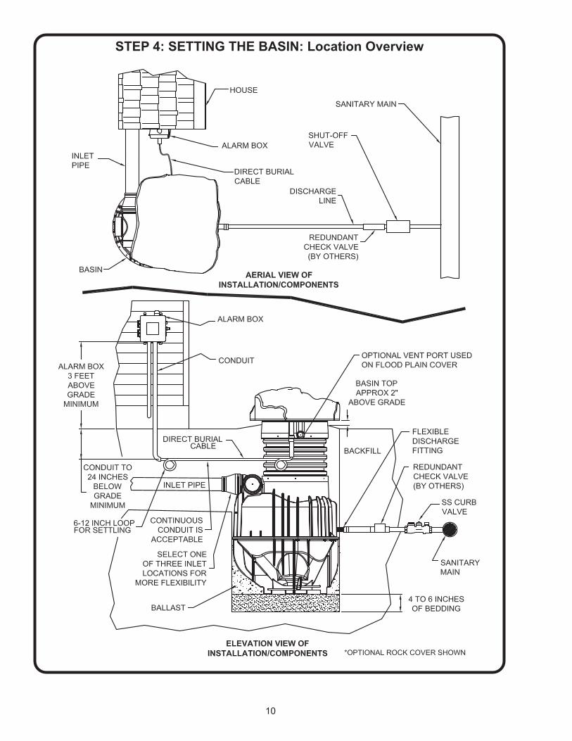
The location of your basin should meet the following conditions:• Not placed in low lying or frequently flooded areas • Ground slopes away from the basin • Have well draining soil• Removed from normal traffic routes• Close proximity to the structure sewage is originating from to minimize bends and overall inlet line length.• Does not damage foundations of structures
• Placed in an area accessible to authorized personnel at all times
STEP 4: SETTING THE BASIN: Location Overview
10
STEP 4: SETTING THE BASIN: Location Overview
11
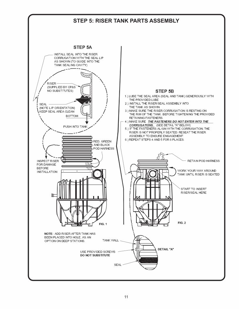
STEP 5: RISER TANK PARTS ASSEMBLY

12
To calculate the hole depth required, add the package depth plus the amount of bedding used under the tank, then subtract 2 inches. Package depth plus bedding thickness minus two inches = Hole depth required.
BEDDING MATERIALDESCRIPTION - The basin should have a 4 to 6 inch compacted bed of round or angular crushed rock with a minimum size of 1/8” and no larger than ¾”. The bedding should be placed and compacted using a hand or vibratory tamper
HANDLING THE BASINImproper handling could result in fractures or permanent structural damage. Handle the tank in a vertical manner whenever possible.
• Never place a chain around the basin when moving the tank. • Only use a nylon lifting strap or similar device around the tank.
• Never lift the package by the riser or the cover.• Never drag, drop, or roll package.• Do not install pump until basin assembly has been backfilled around.
Once the package is installed in the hole, place a level on top of the Adapter flange. The package should be level within half a bubble. If the package is not level, lift tank from hole and level bedding material out.
Never try to level the package out by pushing down on top of package with excavating equipment. Warranty will be voided if attempted.
STEP 6: HOLE DEPTH & BASIN HANDLING

13
7BApply thread sealant to the threads of the NPT to SLIP fitting that is on the direct burial cable. Thread and tighten the fitting into the adapter.
STEP 7: ADAPTER / CONDUIT LAYOUT
7ACut drain tile to proper elevation at bottom of corrugation• Optional Methods - Miter Saw or Sawzall®
IF EXTENSION IS REQUIRED TO BRING DRAIN TILE ABOVE GRADE LEVEL, USE CRANE PUMPS & SYSTEMS’ DRAIN TILE EXTENSION KIT P/N: 123510
14
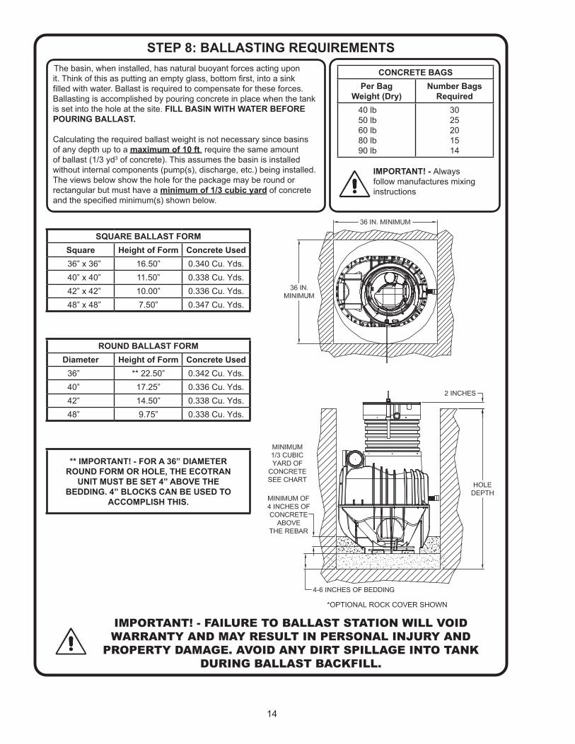
The basin, when installed, has natural buoyant forces acting upon it. Think of this as putting an empty glass, bottom first, into a sink filled with water. Ballast is required to compensate for these forces. Ballasting is accomplished by pouring concrete in place when the tank is set into the hole at the site. FILL BASIN WITH WATER BEFORE POURING BALLAST.
Calculating the required ballast weight is not necessary since basins of any depth up to a maximum of 10 ft. require the same amount of ballast (1/3 yd3 of concrete). This assumes the basin is installed without internal components (pump(s), discharge, etc.) being installed. The views below show the hole for the package may be round or rectangular but must have a minimum of 1/3 cubic yard of concrete and the specified minimum(s) shown below.
STEP 8: BALLASTING REQUIREMENTS
IMPORTANT! - FAILURE TO BALLAST STATION WILL VOID WARRANTY AND MAY RESULT IN PERSONAL INJURY AND
PROPERTY DAMAGE. AVOID ANY DIRT SPILLAGE INTO TANK DURING BALLAST BACKFILL.
CONCRETE BAGSPer Bag
Weight (Dry)Number Bags
Required40 lb50 lb60 lb80 lb90 lb
3025201514
IMPORTANT! - Always follow manufactures mixing instructions
SQUARE BALLAST FORMSquare Height of Form Concrete Used36” x 36” 16.50” 0.340 Cu. Yds.40” x 40” 11.50” 0.338 Cu. Yds.42” x 42” 10.00” 0.336 Cu. Yds.48” x 48” 7.50” 0.347 Cu. Yds.
ROUND BALLAST FORMDiameter Height of Form Concrete Used
36” ** 22.50” 0.342 Cu. Yds.40” 17.25” 0.336 Cu. Yds.42” 14.50” 0.338 Cu. Yds.48” 9.75” 0.338 Cu. Yds.
** IMPORTANT! - FOR A 36” DIAMETER ROUND FORM OR HOLE, THE ECOTRAN
UNIT MUST BE SET 4” ABOVE THE BEDDING. 4” BLOCKS CAN BE USED TO
ACCOMPLISH THIS.

15
STEP 9: DISCHARGE CONNECTIONS
The basin is equipped with a female 1.25 inch NPT discharge connection.
Your discharge MUST include the following items:• (1) Flexible pipe coupling –supplied with station to compensate for varied settling rates of backfill materials • (1) Flap style redundant check valve – supplied by others - to prevent backflow from the main into the lateral.
CHECK ORIENTATION TO ENSURE PROPER FLOW.• (1) Shut-off valve – supplied by others - near force main connection for station isolation from main. This valve is to be placed between the force main and redundant check valve• Pipe of proper size and strength for rated conditions – supplied by others
Important Notes about the discharge:• All discharge components should be below frost depth. If above frost depth, all components must be properly insulated to prevent freezing.• Pressure checking of discharge should not exceed 150 PSI! Prior to checking laterals be sure to close the shut-off valve inside the station to avoid damage to basin components. All components of your discharge should have a pressure rating of 150 PSI at 73° F (23°C) or greater.
16
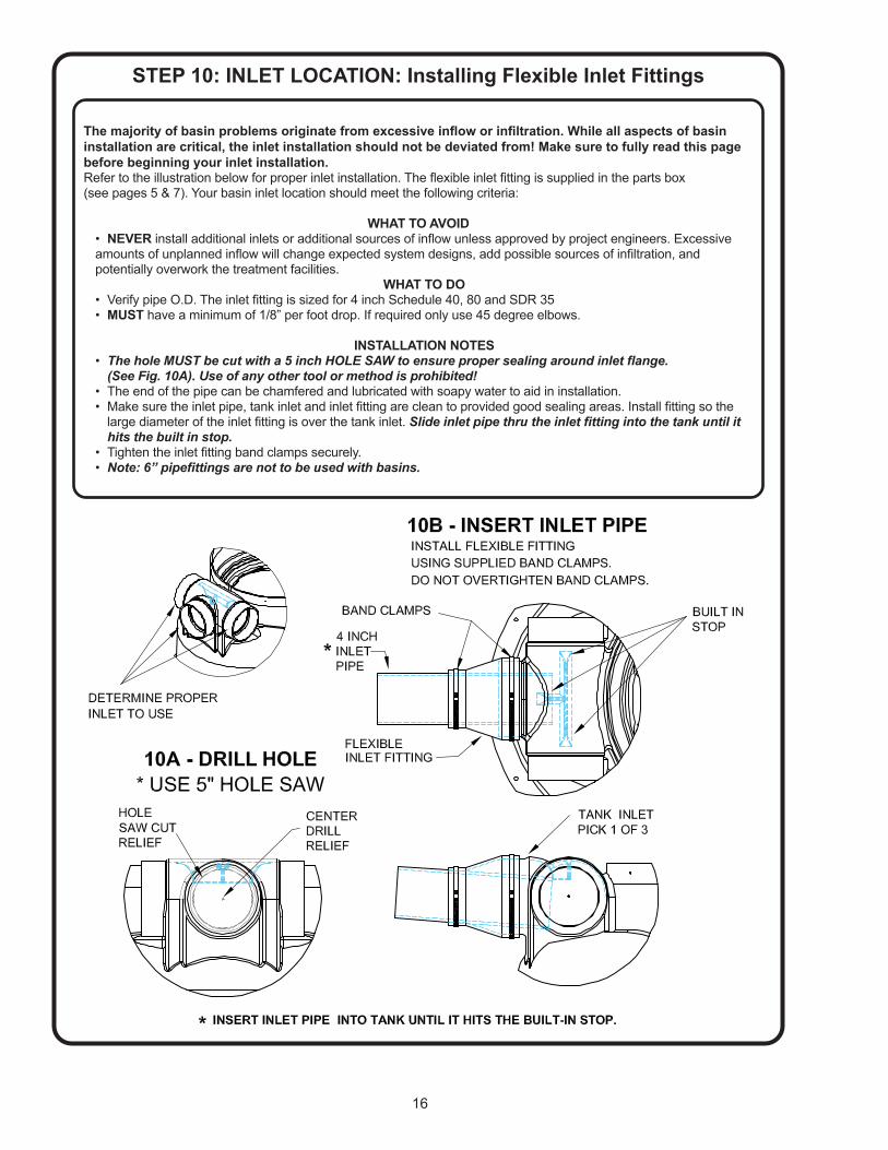
The majority of basin problems originate from excessive inflow or infiltration. While all aspects of basin installation are critical, the inlet installation should not be deviated from! Make sure to fully read this page before beginning your inlet installation.Refer to the illustration below for proper inlet installation. The flexible inlet fitting is supplied in the parts box (see pages 5 & 7). Your basin inlet location should meet the following criteria:
WHAT TO AVOID• NEVER install additional inlets or additional sources of inflow unless approved by project engineers. Excessive amounts of unplanned inflow will change expected system designs, add possible sources of infiltration, and potentially overwork the treatment facilities.
WHAT TO DO• Verify pipe O.D. The inlet fitting is sized for 4 inch Schedule 40, 80 and SDR 35 • MUST have a minimum of 1/8” per foot drop. If required only use 45 degree elbows.
INSTALLATION NOTES• TheholeMUSTbecutwitha5inchHOLESAWtoensurepropersealingaroundinletflange. (See Fig. 10A). Use of any other tool or method is prohibited!• The end of the pipe can be chamfered and lubricated with soapy water to aid in installation.• Make sure the inlet pipe, tank inlet and inlet fitting are clean to provided good sealing areas. Install fitting so the large diameter of the inlet fitting is over the tank inlet. Slideinletpipethrutheinletfittingintothetankuntilit hits the built in stop.• Tighten the inlet fitting band clamps securely.• Note:6”pipefittingsarenottobeusedwithbasins.
STEP 10: INLET LOCATION: Installing Flexible Inlet Fittings
17
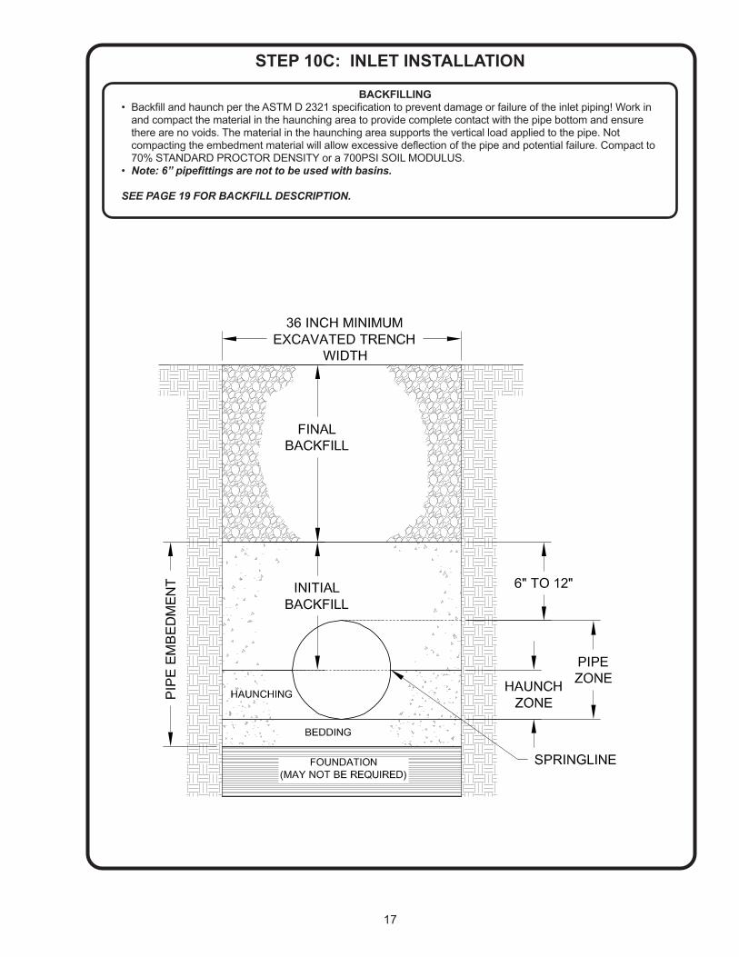
BACKFILLING• Backfill and haunch per the ASTM D 2321 specification to prevent damage or failure of the inlet piping! Work in and compact the material in the haunching area to provide complete contact with the pipe bottom and ensure there are no voids. The material in the haunching area supports the vertical load applied to the pipe. Not compacting the embedment material will allow excessive deflection of the pipe and potential failure. Compact to 70% STANDARD PROCTOR DENSITY or a 700PSI SOIL MODULUS. • Note:6”pipefittingsarenottobeusedwithbasins.
SEE PAGE 19 FOR BACKFILL DESCRIPTION.
STEP 10C: INLET INSTALLATION
18
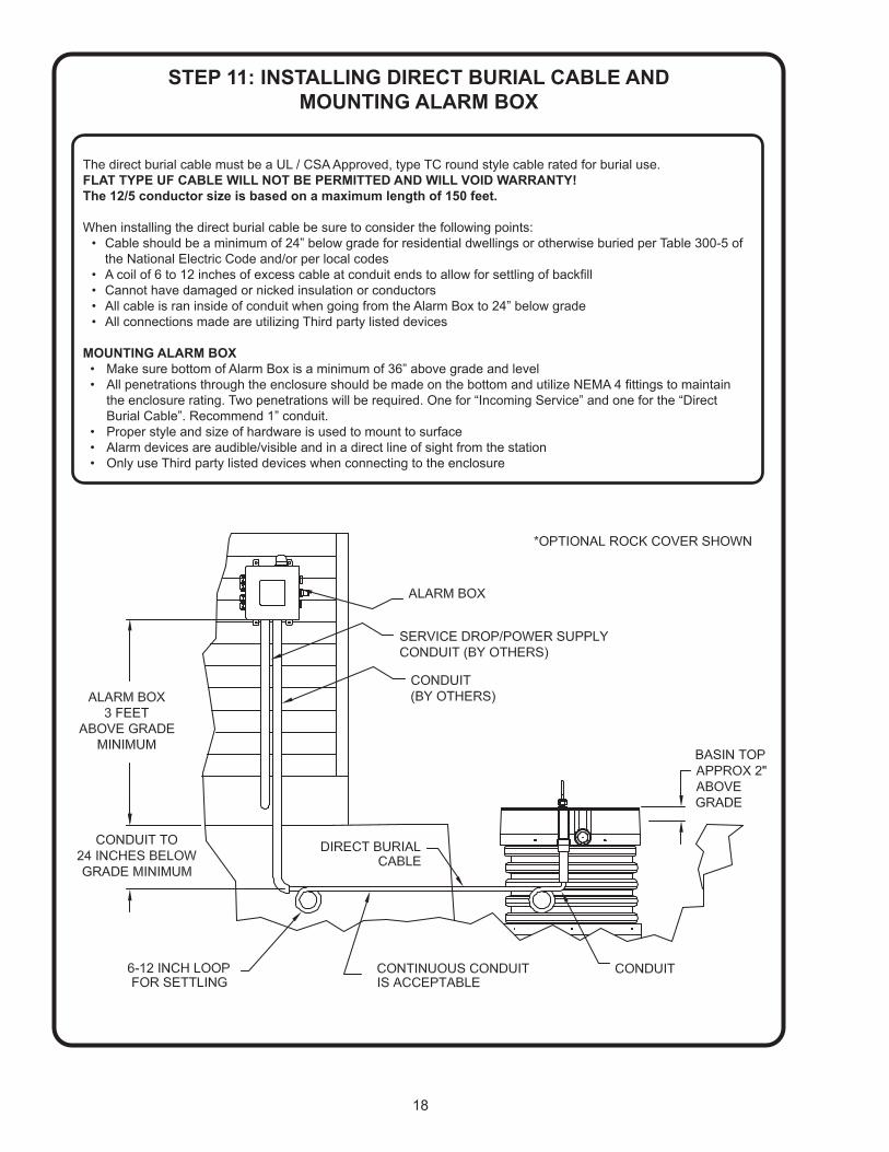
The direct burial cable must be a UL / CSA Approved, type TC round style cable rated for burial use. FLAT TYPE UF CABLE WILL NOT BE PERMITTED AND WILL VOID WARRANTY! The 12/5 conductor size is based on a maximum length of 150 feet.
When installing the direct burial cable be sure to consider the following points:• Cable should be a minimum of 24” below grade for residential dwellings or otherwise buried per Table 300-5 of the National Electric Code and/or per local codes• A coil of 6 to 12 inches of excess cable at conduit ends to allow for settling of backfill • Cannot have damaged or nicked insulation or conductors• All cable is ran inside of conduit when going from the Alarm Box to 24” below grade• All connections made are utilizing Third party listed devices
MOUNTING ALARM BOX• Make sure bottom of Alarm Box is a minimum of 36” above grade and level • All penetrations through the enclosure should be made on the bottom and utilize NEMA 4 fittings to maintain the enclosure rating. Two penetrations will be required. One for “Incoming Service” and one for the “Direct Burial Cable”. Recommend 1” conduit.• Proper style and size of hardware is used to mount to surface• Alarm devices are audible/visible and in a direct line of sight from the station• Only use Third party listed devices when connecting to the enclosure
STEP 11: INSTALLING DIRECT BURIAL CABLE AND MOUNTING ALARM BOX

19
STEP 12: BACKFILLINGWhen backfilling around the basin, care should be taken to prevent damage to the installed components. It is imperative that proper backfill materials and methods be used to prevent leaks, cracks and failures. Listed below are materials approved for backfill per the ASTM D 2321 specification.Any other material used will void warranty!
Angular Aggregate, Open Grade, Class IA Materials - Class IA materials provide maximum stability and support for a given density due to angular interlock of particles. With minimum effort these materials can be installed at relatively high densities over a wide range of moisture contents. In addition, the high permeability of Class IA materials may aid in the control of water, and these materials are often desirable for embedment in rock cuts where water is frequently encountered. However, when ground water flow is anticipated, consideration should be given to the potential for migration of fines from adjacent materials into the open-graded Class IA materials. Examples of material types: Angular, crushed stone or rock, crushed gravel, broken coral; contain little or no fines.
Aggregates, Dense Grade, Class IB Materials - Class IB materials are processed by mixing Class IA and sands to produce a particle size distribution that minimizes migration from adjacent materials that contain fines. They are more densely graded than Class IA materials and thus require more compactive effort to achieve the minimum density specified. When properly compacted, Class IB materials offer high stiffness and strength and, depending on the amount of fines, may be relatively free draining. Examples of material types: Angular, crushed stone (or other Class 1A materials) and stone/sand mixtures with gradations selected to minimize migration of adjacent soils; contain little or no fines.
Gravel and Soils, Class II Materials - Class II materials, when compacted, provide a relatively high level of pipe support. In most respects, they have all the desirable characteristics of Class IB materials when densely graded. However, open graded groups may allow migration and the sizes should be checked for compatibility with adjacent material. Typically, Class II materials consist of rounded particles and are less stable than angular materials unless they are confined and compacted. Examples of material types: Graded gravels and gravel-sand mixtures with less than 5 % fines; Sands and gravels, which are borderline between clean and with fines varying from 5 to 12 %. These materials are usually contained with a fabric or other type of liner to provide proper support.
Backfill materials must be free of lumps, clods, boulders, frozen matter, and debris. The presence of such material in the backfill material may prevent uniform compaction and result in cracks, fractures, or deflections.
FINAL GRADING The final grade should slope away from the basin to avoid collecting ground water around the station. Your final grade should be approximately 2” below the top of the basin flange. Any height taller than this may allow freezing to develop inside the station if not properly insulated. The top of the basin should never be below grade. This will allow ground water and sediment to infiltrate into the basin. See illustration below.
20
STEP 13: WIRING THE STATION TO ALARM BOX
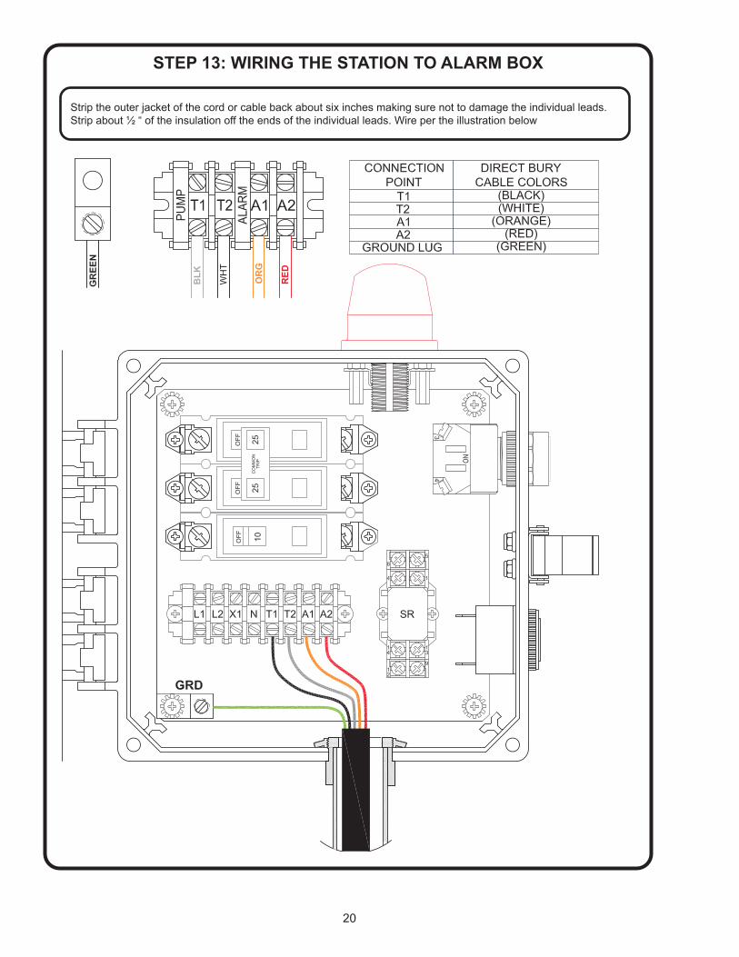
Strip the outer jacket of the cord or cable back about six inches making sure not to damage the individual leads. Strip about ½ “ of the insulation off the ends of the individual leads. Wire per the illustration below
21
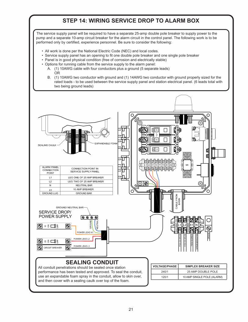
The service supply panel will be required to have a separate 25-amp double pole breaker to supply power to the pump and a separate 10-amp circuit breaker for the alarm circuit in the control panel. The following work is to be performed only by certified, experience personnel. Be sure to consider the following:
• All work is done per the National Electric Code (NEC) and local codes. • Service supply panel has an opening to fit one double pole breaker and one single pole breaker • Panel is in good physical condition (free of corrosion and electrically stable) • Options for running cable from the service supply to the alarm panel: A. (1) 10AWG cable with four conductors plus a ground (5 separate leads) OR B. (1) 10AWG two conductor with ground and (1) 14AWG two conductor with ground properly sized for the rated loads - to be used between the service supply panel and station electrical panel. (6 leads total with two being ground leads)
STEP 14: WIRING SERVICE DROP TO ALARM BOX
SEALING CONDUITAll conduit penetrations should be sealed once station performance has been tested and approved. To seal the conduit, use an expandable foam spray in the conduit, allow to skin over, and then cover with a sealing caulk over top of the foam.
VOLTAGE/PHASE SIMPLEX BREAKER SIZE
240/1 25 AMP DOUBLE POLE
120/1 10 AMP SINGLE POLE (ALARM)

22
Step 16: INSTALLING THE PUMP CORD AND LEVEL
CONTROL CORDInsert the end of the cord plug into the housing bore, aligning the alignment mark of the plug with the alignment hole of the terminal block (see below). Tighten bolts on compression flange until it touches the housing.
Pump Power - Large pinLevel Control - Small pinLevel control cord has molded fitting at both ends of the cord. Install one end to the Pump and the other end to the Level Control.
Step 15: INSTALL PUMP HARNESSTie the bowline knot where shown per the directions provided. Tie one bowline knot on the handle of the moveable fitting and one bowline knot in the eyebolt on the pump.

23
The nameplate is located on top of the pump. This contains the pumps part number, horsepower voltage, phase, and serial number, as well as other information. The start-up form located in the back of this manual contains a place to record this data. The information should be recorded now so the pump does not have to be pulled again later. The start-up form can be left in the control panel until station start-up is completed later.
Step 17: RECORDING PUMP NAMEPLATE INFORMATION
Step 18: INSTALLING THE PUMP
The pump has an integral valve/upper moveable and support flange. This will guide the pump down the guide rail and rest on the stop built into the POD (Pump Orienting Device). Check to make sure the check valve is aligned as shown before lowering into the guide rail. When lowering or lifting the pumps always use the lifting device and appropriate lifting equipment.
NEVER MOVE THE PUMP BY THE POWER CORD! ALWAYS INSTALL PUMP BEFORE LEVEL CONTROL. DO NOT DROP THE PUMP!
Step 19: INSTALLING THE LEVEL CONTROLThe level control
has a unique shape. This will fit into the pocket shaped to
accept it in the POD next to the pump as shown below. Lower the level control into the pocket as shown
below which will automatically set the correct height off the
basin bottom.
24
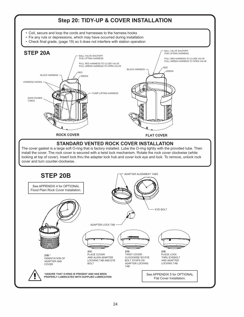
Step 20: TIDY-UP & COVER INSTALLATION
• Coil, secure and loop the cords and harnesses to the harness hooks• Fix any ruts or depressions, which may have occurred during installation.• Check final grade, (page 19) so it does not interfere with station operation
STANDARD VENTED ROCK COVER INSTALLATIONThe cover gasket is a large soft O-ring that is factory installed. Lube the O-ring lightly with the provided lube. Then install the cover. The rock cover is secured with a twist lock mechanism. Rotate the rock cover clockwise (while looking at top of cover). Insert lock thru the adapter lock hub and cover lock eye and lock. To remove, unlock rock cover and turn counter-clockwise.
See APPENDIX 4 for OPTIONAL Flood Plain Rock Cover Installation.
See APPENDIX 5 for OPTIONAL Flat Cover Installation.
25
Step 21: START UP PRE-CHECKLIST
Prior to performing an electrical and hydraulic performance check of the complete station, verify all of the following criteria are met:
The shut-off and redundant check valve at force main are installed in the lateral discharge and are in the open position
Discharge piping has been pressure tested to 150 PSI max without leakage Inlet has a minimum of 1/8” per foot drop All penetrations through basin and electrical enclosure sealed water-tight Proper backfill and compaction has been done to prevent deflection or possible failure of equipment All cords are secured and clear of pump cutter and level control Electrical supply is of proper voltage, phase for the pump A properly sized double pole circuit breaker has been installed in the service disconnect panel Proper gauge and conductor wire installed from service disconnect to house panel All terminal connections are secure Circuit breakers in the Alarm Box are turned to the “OFF” position Circuit breaker in the service disconnect turned to “ON” Pump is properly seated on the discharge opening in the rail Level control is installed properly Final grade slopes away from the basin to avoid runoff water collection/ basin inflow All construction and shipping debris has been removed from the basin
Step 22: START-UP CHECKLIST
Water has been added to the basin to a level of approximately 1” above the pump support flange Valve(s) within the basin and lateral are in the “OPEN” position (Pull on Green Strap in station) Record pump and basin nameplate information on the start-up form (Before installing pump) All alarm devices are turned to the “ON” position Complete START-UP check sheet located in the back of the manual

26
TROUBLE SHOOTING - EcoTRANCAUTION ! Always disconnect the pump from the electrical power source before handling.If the system fails to operate properly, carefully read instructions and perform maintenance recommendations.If operating problems persist, the following chart may be of assistance in identifying and correcting them:MATCH “CAUSE” NUMBER WITH CORRELATING “CORRECTION” NUMBER.
PROBLEM CAUSE CORRECTIONPump will not run 1. Poor electrical connection, blown fuse,
tripped breaker or other interruption of power, improper power supply.2. Motor inoperative3. Level control inoperative.4. Insufficient liquid level.
1. Check all electrical connections for security. Have electrician measure current in motor leads, if current is within ±20% of locked rotor Amps, impeller is probably locked. If current is 0, overload may be tripped. Remove power, allow pump to cool, then recheck current.2. Check winding insulation (Megger Test) and winding resistance. If check is outside of range, dry and recheck, If still defective, replace per service instructions.3. Remove Level Control. Orient the ESPS
Switch horizontally. If the pump still does not operate, after rechecking all electrical connections, replace the level control. Holding the SensaPRO as it would be orientated in the tank, raise the float up then lower the float to a vertical hanging position. If the pump still does not operate, after rechecking all electrical connections, replace the level control.
4. Make sure liquid level is at least equal to suggested turn-on point.5. Recheck all sizing calculations to determine pump type.6. Check discharge line for restrictions, including ice if line passes through or is into cold areas.7. Remove and examine check valve for freedom of operation.8. Open valve.9. Check impeller for freedom of operation security and condition. Clean impeller cavity and inlet of any obstruction.10. Check and clean anti-siphon.11. Repair fixtures as required to eliminate leakage.12. Check for leaks.13. Check pump and level control temperature limits and fluid temperature.
Pump will not turn off 2. Motor inoperative3. Level control inoperative.5. Excessive inflow or pump not properly sized for application.10. Pump may be airlocked.
Pump hums but does not run 1. Incorrect voltage9. Impeller jammed or loose on shaft, worn or damaged, impeller cavity or inlet plugged.
Pump delivers insufficient capacity 1. Incorrect voltage.5. Excessive inflow or pump not properly sized for application.6. Discharge restricted.7. Check valve stuck closed8. Shut-off valve closed.9. Impeller jammed or loose on shaft, worn or damaged, impeller cavity or inlet plugged.10. Pump may be airlocked.
Pump cycles too frequently or runs periodically when fixtures are not in use
7. Check valve stuck closed11. Fixtures are leaking.12. Ground water entering basin.
Pump shuts off and turns on indepen-dent of switch, (trips thermal overload protector). CAUTION! Pump may start unexpectedly. Disconnect power supply.
1. Incorrect voltage.5. Excessive inflow or pump not properly sized for application.9. Impeller jammed, loose on shaft, worn or damaged, impeller cavity or inlet plugged.13. Excessive water temperature.
Pump operates noisily or vibrates excessively
2. Worn bearings or bent shaft8. Debris in impeller cavity or broken impeller
27
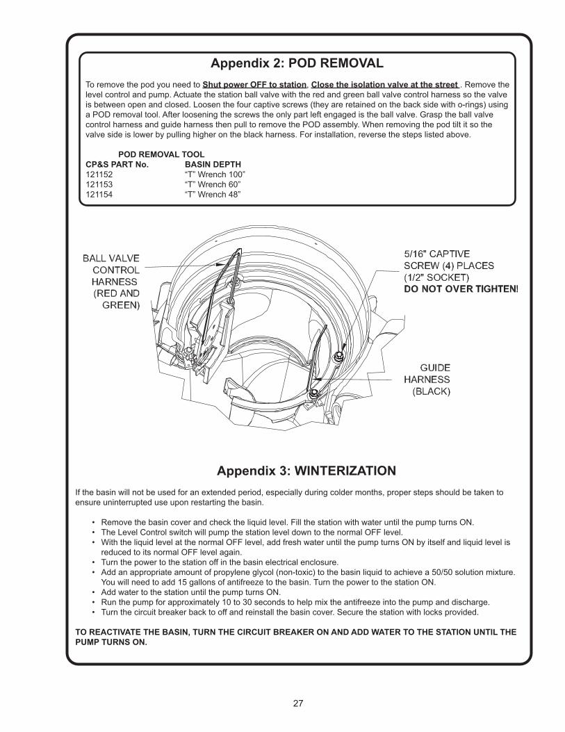
Appendix 2: POD REMOVALTo remove the pod you need to Shut power OFF to station, Close the isolation valve at the street . Remove the level control and pump. Actuate the station ball valve with the red and green ball valve control harness so the valve is between open and closed. Loosen the four captive screws (they are retained on the back side with o-rings) using a POD removal tool. After loosening the screws the only part left engaged is the ball valve. Grasp the ball valve control harness and guide harness then pull to remove the POD assembly. When removing the pod tilt it so the valve side is lower by pulling higher on the black harness. For installation, reverse the steps listed above.
POD REMOVAL TOOLCP&S PART No. BASIN DEPTH121152 “T” Wrench 100”121153 “T” Wrench 60”121154 “T” Wrench 48”
Appendix 3: WINTERIZATIONIf the basin will not be used for an extended period, especially during colder months, proper steps should be taken to ensure uninterrupted use upon restarting the basin.
• Remove the basin cover and check the liquid level. Fill the station with water until the pump turns ON.• The Level Control switch will pump the station level down to the normal OFF level. • With the liquid level at the normal OFF level, add fresh water until the pump turns ON by itself and liquid level is reduced to its normal OFF level again. • Turn the power to the station off in the basin electrical enclosure.• Add an appropriate amount of propylene glycol (non-toxic) to the basin liquid to achieve a 50/50 solution mixture. You will need to add 15 gallons of antifreeze to the basin. Turn the power to the station ON.• Add water to the station until the pump turns ON.• Run the pump for approximately 10 to 30 seconds to help mix the antifreeze into the pump and discharge.• Turn the circuit breaker back to off and reinstall the basin cover. Secure the station with locks provided.
TO REACTIVATE THE BASIN, TURN THE CIRCUIT BREAKER ON AND ADD WATER TO THE STATION UNTIL THE PUMP TURNS ON.
28
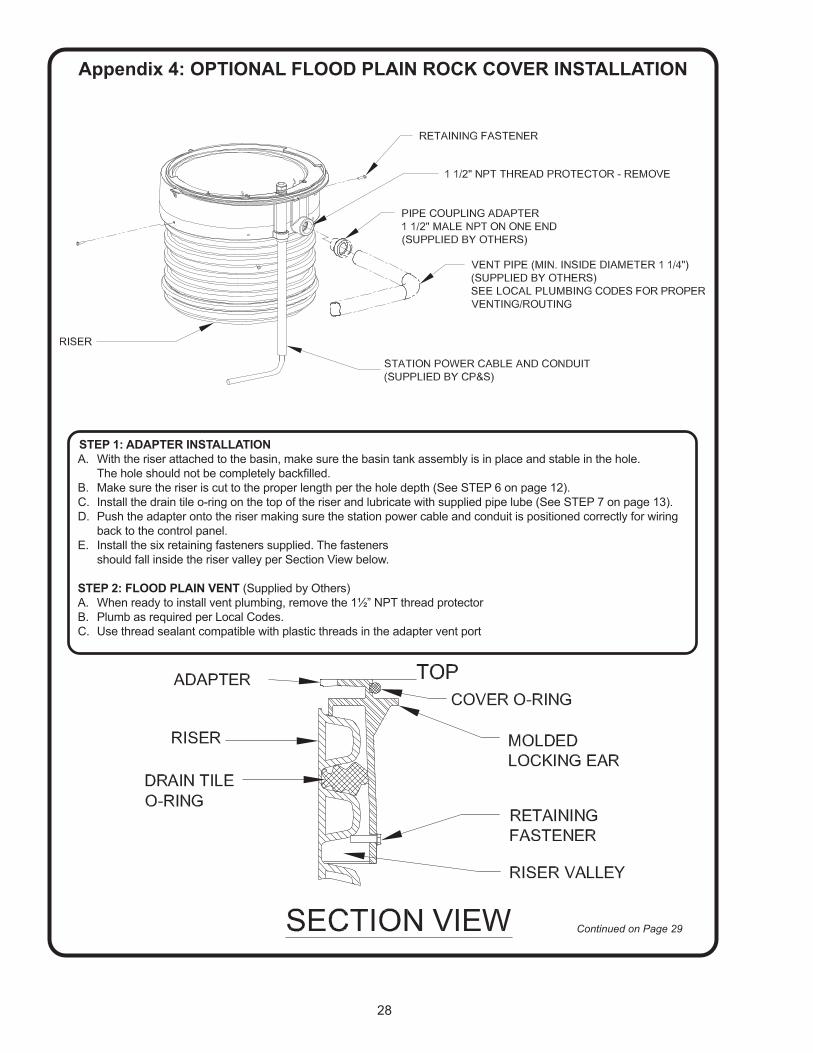
STEP 1: ADAPTER INSTALLATIONA. With the riser attached to the basin, make sure the basin tank assembly is in place and stable in the hole. The hole should not be completely backfilled.B. Make sure the riser is cut to the proper length per the hole depth (See STEP 6 on page 12).C. Install the drain tile o-ring on the top of the riser and lubricate with supplied pipe lube (See STEP 7 on page 13).D. Push the adapter onto the riser making sure the station power cable and conduit is positioned correctly for wiring back to the control panel.E. Install the six retaining fasteners supplied. The fasteners should fall inside the riser valley per Section View below.
STEP 2: FLOOD PLAIN VENT (Supplied by Others)A. When ready to install vent plumbing, remove the 1½” NPT thread protectorB. Plumb as required per Local Codes.C. Use thread sealant compatible with plastic threads in the adapter vent port
Appendix 4: OPTIONAL FLOOD PLAIN ROCK COVER INSTALLATION
Continued on Page 29
29
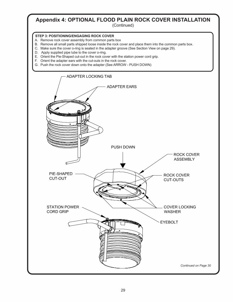
STEP 3: POSITIONING/ENGAGING ROCK COVERA. Remove rock cover assembly from common parts boxB. Remove all small parts shipped loose inside the rock cover and place them into the common parts box.C. Make sure the cover o-ring is seated in the adapter groove (See Section View on page 29).D. Apply supplied pipe lube to the cover o-ring.E. Orient the Pie-Shaped cut-out in the rock cover with the station power cord grip.F. Orient the adapter ears with the cut-outs in the rock cover.G. Push the rock cover down onto the adapter (See ARROW - PUSH DOWN)
Appendix 4: OPTIONAL FLOOD PLAIN ROCK COVER INSTALLATION(Continued)
Continued on Page 30
30
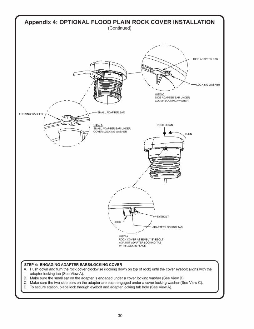
Appendix 4: OPTIONAL FLOOD PLAIN ROCK COVER INSTALLATION(Continued)
STEP 4: ENGAGING ADAPTER EARS/LOCKING COVERA. Push down and turn the rock cover clockwise (looking down on top of rock) until the cover eyebolt aligns with the adapter locking tab (See View A).B. Make sure the small ear on the adapter is engaged under a cover locking washer (See View B).C. Make sure the two side ears on the adapter are each engaged under a cover locking washer (See View C).D. To secure station, place lock through eyebolt and adapter locking tab hole (See View A).

31
Appendix 5: OPTIONAL FLAT COVER INSTALLATION
STEP 1: ADAPTER INSTALLATIONA. With the riser attached to the basin, make sure the basin tank assembly is in place and stable in the hole. The hole should not be completely backfilled.B. Make sure the riser is cut to the proper length per the hole depth (See STEP 6 on page 12).C. Push the adapter onto the riser making sure the station power cable and conduit is positioned correctly for wiring back to the control panel.D. In order to determine correct engagement of the adapter onto the riser, press the adapter onto the riser until the J-hook in the adapter comes into contact with the riser per Section View below.E. Install the six retaining fasteners supplied. The fasteners should fall inside the riser valley per Section View below.
STEP 2: FLOOD PLAIN VENT (Supplied by others)A. Insert male threaded 1¼” pipe coupling adapter into vent port.B. Plumb as required per Local Codes. Use thread sealant compatible with plastic threads in the adapter vent port. Thread 1¼” locknut onto male NPT side adapter.
STEP 3: POSITIONING/ENGAGING FLAT COVERA. Remove flat cover assembly from common parts box.B. Remove all small parts shipped loose inside the flat cover adapter and place them into the common parts box.C. Orient cover over adapter, lining up the bolt holes. D. Place washers on all six, 3/8-16, 1.25” screws and tighten screws into cover until tight.
STEP 4: OPTIONAL NON-FLOOD PLAIN VENT INSTALLATIONA. Tighten 2” PVC Nipple into Bug Free Vent. Tighten opposite end of 2” PVC Nipple into central threaded flange in Flat Cover Assembly.
32

33
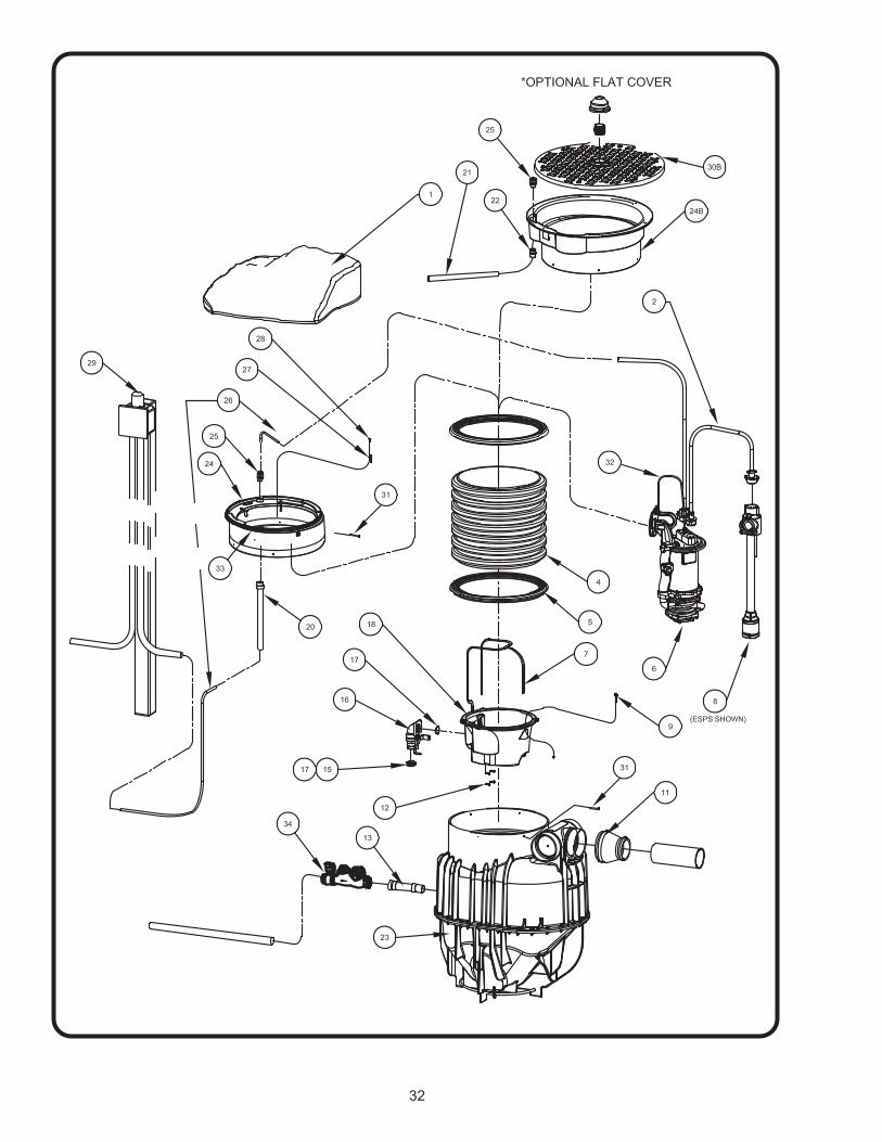
PARTS LISTITEM QTY. PART No. DESCRIPTION
1 1 119043119043N
Poly Cover, Rock, SandstonePoly Cover, Rock, Sandstone (Non Vent)
2 1 113315113315A
Level Control, Power, 15FtLevel Control, Power, 8Ft
4 1118241H118241J118241C
Riser 78 inchRiser 59.5 inchRiser 40 inch
5 2 118240 Riser Seal
6 1 119969119973
Pump, OGPPump, OGV
7 1 120247120247A
POD Harness, LongHarness, Short
8 1 119068142571
ESPS Automatic Level ControlSensaPRO Mechanical Float
9 4 118262 Hex Hd Cap Screw WH .31-18 x 1.68” Lg10 4 2-31003-202 O-Ring11 1 116969 Flexible Inlet Fitting12 4 119081 FHHS Screw 1/4-20 x 1.00” Lg13 1 100159 Flexible Discharge Fitting15 1 118259AR Valve-Receiver Grommet16 1 118245 Ball Valve17 2 625-01558 O-Ring18 1 118247 POD20 1 140034 Conduit with Adapter, 1 inch21 1 141207 Conduit22 1 141206 Adapter23 1 119069 EcoTRAN Tank Assembly24 1 118239A Adapter
24A24B 1 140591
140591AAdapter, Flat Cover, Vent, 24”Adapter, Flat Cover, No Vent, 24”
25 1 094270 Cord Grip
26 1123049123049A123049C
30 Ft. Electrical Connection 12/5 DBC50 Ft.100 Ft
27 2 119088 Cord Hook28 2 118249 PH PanHd Screw 1/4-10 x .75” Lg
29 1 111666116742
Panel, Alarm/Auto with Gen. RecepticlePanel, Alarm/Auto
30A30B
11
107994101786A
Cover, Fiber, Basin, 24” (Not Shown)Cover, Fiber, Basin, 24”
31 12 118265 Riser Retainer Fasteners HxHd 1/4-20 x 1.50” Lg
32 1 093973099286
Pump Harness, ShortPump Harness, Long
33or
33A
1 2-31003-470 Gasket, Cover, Nitrile, Standard Vented Cover
1 120780 Gasket, Cover, Silicone, Flood Plain Cover
34or
34A
1 141287 Curbstop, Check Valve, 1.25” (Purchased Separately)
1 141551 Curbstop, Check Valve, 2.00” (Purchased Separately)
1 085116 Swing Check Valve, 1.25” NPT (Purchased Separately)

Notes

IMPORTANT!WARRANTY REGISTRATION
Your product is covered by a warranty: www.cranepumps.com/downloadables/CATALOGS_OIPMs/Warranty/24MonthWarranty.pdf
If you have a claim under the provisions of the warranty, contact your local Crane Pumps & Systems, Inc. Distributor.
RETURNED GOODSRETURN OF MERCHANDISE REQUIRES A “RETURNED GOODS AUTHORIZATION”.
CONTACT YOUR LOCAL CRANE PUMPS & SYSTEMS, INC. DISTRIBUTOR.
Products Returned Must Be Cleaned, Sanitized, Or Decontaminated As Necessary Prior To Shipment, To Insure That Employees Will Not Be Exposed To Health Hazards In Handling Said Material. All Applicable Laws And Regulations Shall Apply.
IMPORTANT!WARRANTY REGISTRATION
Your product is covered by the enclosed Warranty.
If you have a claim under the provision of the warranty, contact your local Crane Pumps & Systems, Inc. Distributor.