ed 339 861 cs 059 796 author insolia, gerard … design; *computer assisted manufacturing; ......
TRANSCRIPT

DOCUMENT RESUME
ED 339 861 CS 059 796
AUTHOR Insolia, GerardTITLE Computer Aided Manufacturing.INSTITUTION Northampton Community Coll., Bethlehem, PA.SPONS AGENCY Office of Vocational and Adult Education (ED),
Washington, DC.PUB DATE 91CONTRACT V100A00063-90NOTE 111p.; For related documents, see CE 059 793-795.PUB TYPE Guides - Classroom Use - Teaching Guides (For
Teacher) (L52)
EDRS PRICE mFo1/Pco5 Plus Postage.DESCRIPTORS College Programs; Community Colleges; Computer
Assisted Design; *Computer Assisted Manufacturing;Computer Science; *Computer Software; CourseDescriptions; Industrial Education; *IndustrialTraining; Job Training; Numerical Control; ResourceCenters; Retraining; Technical Education;*Technological Advancement; Two Year Colleges
IDENTIFIERS Northampton County Area Community College PA;Programable Logic Control
ABSTRACTThis document contains course outlines in
computer-aided manufacturing developed for a business-industrytechnology resource center for firms in eastern Pennsylvania byNorthampton Community College. The four units of the course cover thefollowing: (1) introduction to computer-assisted design(CAD)/computer-assisted manufacturing (CAM); (2) CAM requirementanalysis; (3) CAM software and evaluation; and (4) SMARTCAM.Exercises and transparency masters are included. Appendixes consistof part drawings, "hot key" definitions, and an outline of aprogrammable logic controls workshop. (MC)
** ********** ***************** ***** ************************************** Reproductions supplied by EDRS are the best that can be made *
* from the original document. *
***********************************************************************

- 'Iv,-a' t 4
COMPUTER AIDEDMANUFACTURING
Developed byGerard Ins° lia
U DEPANTWENT Of EDUCATION
Office at Educations) Romerca and innavorwrisint
ED ATIONAL RESOURCES INFORMATIONCENTER (Ewa
Trim docurnont hat bean reproduced esreceived f (Orr ft** OfIrSOn Of OfOlnamf.oncaliamong
r lovtof crtangas nava upon inabe 10 anra Owflip+ Of:lotted' [wind y
Points of vivror or motions stated in :hos doc
ment Oo not nOORtIcanty ftOnllif of Ott fCatt
Of RI position or policy
Center for Business & IndustryONorthampton Community College
3835 Green Pond RoadBethlehem, PA 18017
1991
11..111111111e11111111.
2
BEST COPY AVAILABLE

Special acknowledgement to the followingorganizations for documentation used in this
training program:
Point Control Co.
Northeast Manufacturing Technology Center (NEMTC)Rennsalear Polytechnical Institute
Rennsalear, New York

OUTLINE: COMPUTER AIDED MANUFACTURING
I. INTRODUCTION1. Rationale for CAD/CAM2. CAD/CAM Hardware3. CAD/CAM Software4. CAD-to-CAM Interface5. CAM-to-CNC Interface
Objective; Give the student a perspective of CAM that includes why CAMis used, how it is implemented, and how it affects other areas of
the company.
IL CAM REQUIREMENTS ANALYSIS1. Part Analysis2. CNC Machine Tools3. CAM Requirement4. CAD System5. Workforce
IIL CAM SOFTWARE EVALUATION1. General Operation2. System Types3. Editing4. CAD Interfaces5. Post Processors6. User Skupoport7. Cost Estimates8. Evaluation
IV. SMARTCAM1. Capabilities2. Available Functions3. General Method of Use4. User Interface5. Preparing to Write a Program6. Process Modeling7. Generating CNC Code8. Editing Code9. Communications

I. INTRODUCTION
1. Rationale for CAD/CAM
2. CAD/CAM Hardware
3. CAD/CAM Software
4. CAD to CAM Interface
5. CAM to CNC Interface
Definitions:
CAD Computer Aided DesignCAM Computer Assisted MachiningCNC Computer Numerical Control
5

I. INTRODUCTION
1. Rationale for CAD/CAM
Increased productivity
Better quality products
Better communications
Integrated design & manufacturingModeling - product & processAnalysis - multiple conditionsReview check accuracyDocumentation!!
Reduced prototype costs
Faster response to customers

I. INTRODUCTION
2. CAD/CAM Hardware
a. Operator Input Devices
MouseKeyboardDigitizing TabletTrackball, Joystick
b. Computer
Central Processing Unit (CPU)Memory (RAM)Primary Storage (Hard Disk)Secondary Storage (Floppy Disk)Floating Point Processor (optional)
c. Output Devices
MonitorPrinterPlotterDisk Drives, Tape Drives
I. INTRODUCTION
3. CAD/CAM Software
a. Operating System
DOSUNIX, XENIX, AIXOS/2Network Operation System
b. Application Program
CAM SystemCAD SystemPostprocessor
c. Utilities
Translators (CAD to CAM)Communications (CAM to CNC)

I. INTRODUCTION
4. CAD to CAM Interface
IGESDXFCADLVDA-FSPDES
Translators allow geometry files tobe exchanged wth various CADsystems.
Shared Database Elements:mathematical modelsgraphic imagesbills of materialsparts listssize, formlocational dimensionstolerance specificationsmaterial specifications
I. INTRODUCTION
5. CAM to CNC Interface
No standard protocolMany proprietary designsHistorically high integration costs
Typically RS-232-C serial linkphysical connection and voltagelevel specification only
Protocol variesdata format, transmissionmode, baud rate, parity,handshaking

II. CAM REQUIREMENT ANALYSIS
1. Part Analysis
2. CNC Machine Tools
3. CAM Requirements
4. CAD System
5. Workforce
1 1
II. CAM REQUIREMENT ANMNSIS
1. Part Analysis
Part DescriptionSize and type of materialComplexity of designs
tool changesmultiple fixtures
Precision
Quantity per Part CycleNumber of parts/cycleCycle timeMachine usageMachine down-time
Projection for FutureExpand businessIncrease quantityIncrease precisionIncrease 3D partsIncrease machine tool types
(mill, lathe, EDM, grinder,laser, punch, CMM, .
12

II. CAM REQUIREMENT ANALYSIS
2. CNC Machine Tools
Machine tool types & descriptionvariety of machinessimultaneous axis operationsunique requirements
Controllersvariety of controllersavailability of postprocessorsunique requirements
Program transfertape/diskdirect connection (hard wired)local area network (LAN)
Futureincreased axis operationsquantity of machinesvariety of machines
1 3

II. CAM REQUIREMENT ANALYSIS 1
13. CAM Requirements
IReview part complexityo linear/circular interpolation Po drilling patterns/arrays Ao pockets, pocket contourso pockets with islands/holes Io part arrayso ruled surfaceso complex surfaces, multi-axis Io global blend radii
IMacro capabilityrepeated sequences to save I
Parametric programmingfamily of parts, user variables I
Communication/Translation filesIGES, DXF, CADL, others I
Operating systems 1DOS, UNDE, MACINTOSH,.
III
1 41
I

Spun surfaoa.
Translated surface.
Ruled surface.
Reproduced with permission of Point Control Co.

tatted surface.
Foal Patch surface.
Reproducod with permission of Point Control Co.

II. CAM REQUIREMENT ANALYSIS
4. CAD System
In-House system(s)design and drafting of partsdetail drawings of partsCAD to be transfered to CAM
Communication filesIGES, DXF, CADL, others
Operating systemsDOS, UNIX, MACINTOSH,.
Hardwaremicroprocessordisplay resolution and VRAMinput devices (mouse, tablet,...)output devices (printer/plotter)
Future

II. CAM REQUIREMENT ANALYSIS
5. Workforce
Engineering/Drafting environmento design engineerso product engineerso drafting
CAD knowledge requirementso CAD drafting/design functionso CAD drafting/updateo CAD drafting/transfer
CAM knowledge requirementso CNC programmerso CAM programmers
Future workforceo train designers in machiningo train CAM programmers to
CADo evaluate local workforce for
availability of needed skills
I S

III. CAM SOFTWARE EVALUATION
1. General Operation
2. System Types
3. Editing
4. CAD Interface
5. Post Processors
6. User Support
7. Cost Estimate
8. Sample Evaluation
! i

1
III. CAM SOFTWARE EVALUATION
1. General Operations
Design to Manufactureo CAD to CAM vs. CAM onlyo in-house CAD vs. vendor CAD
Issues:CAD layerswho designs?who CAMs?
User Interfaceo words meaningful to CNC opso feedback of current stateo promptso on-line HELPo "hot keys", function keyso mixed input modes (keyboard
and digitizer or mouse)
Performanceo result time
111
o through-put time

% CAD TO CAM
VENDOR SOURCE IN-HOUSE CAD
PRINTS
METEELECTRONIC
C4M PROGRAMME
% CAM DIRECT
VENDOR SOURCE
PRINTS
DISKETTE
ELECTRONIC
CAM PROGRAMMER
Reproduced with permission of NEKTC
2 1

SETUP GEOMETRY TRANSFORM INQUIRE TOOLCIIII3 DISPLAY EDIT
IonloiN)
t
ta_taidj.,
FILES AtiteCNIAttextDxfinDxfoutEnd
Ext endsPilanIgesinluesota,
RCM
I-otPurgeQui t.SaveUservienu
*MVPSWAMIFRAKSFRM
INQUIREMOIRDISPLAYnitFILES
miSAMse
Din, lament; Orfila enRegesasting drawing.Cowed:
Second p3M; About to rem proceed? (V>
CAM MIDIU/CAD based Screen from AutoCAX CAD/CAM software.
Reproducod with permisaion of NEKTC

MM
Mese
'Aft...Shape
Vork_rlano
Ulm%gateGroup
Pattern
Sarnia=P.1 h
Roughing
GobsMarro
(MI FNEY
imam
IUD RIM MI I=50 Arc CU L 3
'31:1111.1ZU1EM MEMO =122111.0800 0.0900 9.5009 0.0000 9.5080
0.0000 Mittens: vz_rums
MENU cream from SaartCAN ChD/CAJI software.
Reproduced with permission of MEM=
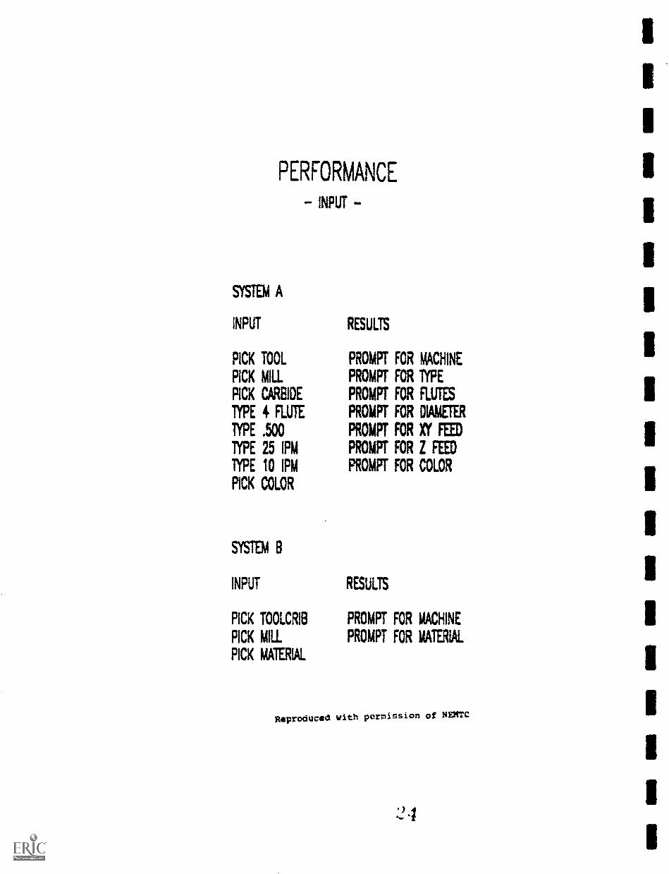
PERFORMANCE
- INPUT -
SYSTEM A
INPUT
PICK TOOL
PICK MIL
PICK CARBIDE
TYPE 4 FLUTE
lYPE .500
TYPE 25 IPM
TYPE 10 1PM
PICK COLOR
MD B
INPUT
PICK TOOLCRIB
PICK MIL
PICK MATERIAL
RESULTS
PROMPT FOR MACHINE
PROMPT FDR TYPE
PROMPT FOR FLUTES
PROMPT FOR DIAMETER
PROMPT FOR XY FEED
PROMPT FOR I FEED
PROMPT FOR COLOR
RESULTS
PROMPT FOR MACHINE
PROMPT FOR MATERIAL
Reproduced with permission of NEM
:24

PERFORMANCE
- PROCESS -
SYSTEM A
CREATE
WINESEQUENCE
SYSTEN B
CREATE
MACHINE
SEQUENCE
CONVERT
TO
POST
pi.MI1GENERATE
MACHINE
CODE
GENERATE
MACHINE
CODE
Reproduced with permission of NENTC

tilt Attribute*iPage up j
Description &darn 4ThatecarbideAutomatic/Manual cheap ATool NumberPreload next tool 1/0FP. OPP
Cage length
1
2!.342
Length comp. I or MaRg.. -1
Spindle speed
Tool diameter
XV feedrete.., 2S
Z feedmte
a4Log: rid .4177ai7,16"Xit-ime'riitz7-r-'?
`:-*tool
Dow
: AU t QOM
fr0 N
penterpulp:fist
pnscrp..lAterscc
1-
A
Tool parameter screen fras AutoCAM software.
Reproduced with permission of NEXTC

Cutter compensation in control : off
Roll cutter around sharp cornersCutter compensation in computer = left center
Tool library: TOOLLTL Naterial: ALLIMI-S
Tool number 1 Dilleter offset = 8 Length offset : 1
gliottt Icliarttoeci to leave : IANFeedrate : 183.35RO Plunge rate : 91.6758 Spindle speed : 18335
Coolant = off
Rapid depth : 9,8808 Contour depth :
Starting sequence number : 188 Increment 2 Program n.
No rotary axis
Linear array: Mx t = 1 1 Dx, : 8.8888
Depth cuts: lough: I cuts at W. * inish: 8 cuts at 8.
HON. position : 110.8088 V8.0888 ZO.8188
Misc. real 111 = 04818 Nisc. integer 111 =
Mill in ri plane
Display: ool (static,endpoints,runodela9 : 8.88) Toolpath
-)Select t s line when through setting parameters
Tool Parametr Scren from MastrCAM 3D software.
Reproduced with permission of NEMTC
'
9

III. CAM SOFTWARE EVALUATION
1. General Operations
CNC Parameter Specificationo fixed order of entryo flexible order of entry
- fuli screen edit- dialogue boxes
Logical Sequenceo operation flow and promptso remember user selectionso customizable interface
Escape Procedureso controlled return or escapeo accept/reject sequence
- parameter screen- dialog box
File Structureo remember user selectionso create correct file .extensions
System Through-Puto function of user task request
and hardwareo upgrade hardware, customize

ESCAPE PROCEDURE
3
STEP 1
STOP I DIME BOUNDARY
2 SPECIFY ROUGH POCKET
3 DIVRZE MAW
4 SPECIFY POCKET OFFSET LEFT
5 ESCAPE
6 SPECIFY POCKET OFFSET RIM
7 SAVE ROUTINE Y/N
Reproduced with permission of NEMTC

FILE STRUCTURE
SYSTEM A
STEP 1 START SOfTWARE
2 ENTER PROGRAM FILENAME
3 ROUI1Nre
4 SAVE FIE
5 EWER PROGRAM FILENAME
6 SHOW GRAPHIC TOOLPATH
7 ENTER PROGRAM ALENAME
8 POST
9 ENTER PROGRAM FIENAME
10 SAVE PROGRAM
11 ENTER PROGRAM FILENAME
12 Eft
SITEN
STEP 1 START SOFTWARE
2 ENTER PROGRAM FILENAME
3 CALL ANY ROME
4 Erc
Reproduced with permission of NEPTC
30

SYSTEM THRU-PUT
30F1V1ARE HARDWARE
INPUT PROCESS
PERFORMANCE
r
CPU DIR
ITHRU-PUT
GRAPHICS
Reproducsd with permission of NEMTC
3 1

I
I
I
HI. CAM SOFTWARE EVALUATION I
I2. System Types
ICAD basedo familiar user interfaceo purchase CAD and CAM Io external postprocessoro slower thru-put (database Iconversions)o easy manipulation of graphicso easy macro functions I
CAM based 1o purchase only CAMo fast thru-put (one database)o possible CAD front-end I
- investigate drafting anddetailing needs Io CAD interfaces are prime
concern (import/export)o internal postprocessor Io limited graphics manipulation
CAM/CAD based Io CAD front-endo fast thru-put (one database) Io internal postprocessoro good graphics manipulation
111
I
I3 442
I

HI. CAM SOFTWARE EVALUATION
3. Editing
Machine Code
o machine tool controller- quick changes
o text editorpart of CAM system
- outside of CAM system
Part Geometry
o edit or change a toolpatho resequence processo graphical change confirmation
Toolpath Parameters
o tool diameter, direction, offset

III. CAM SOFTWARE EVALUATION
4. CAD Interface
Directo CAD to CAM on single layero Toolpaths defined in CAM
- CAD designer not required- CAD software not required- CNC knowledge required
Indirecto CAD operator alters layers to
"fit" CAM systemo Must have access to CAD
software or accept only jobsdedicated to CAM system
.3.1

CAD INTERFACE
SYSTEM "A` MEM 513'
ow CAD.......
DXF DXF
CADL CADL
1GES IGES
DWG ETC.
GEOMETRY
SORTED
GEOMETRY
UNSORTED
TINSIATOR
GEO MY]UNSORTED
Reproduced with permission of NEHTC
? 5

III. CAM SOFTWARE EVALUATION
5. Post Processors
Generic
o usually suppliedo modifid by user to fit needs
Custom
o proven for specificcontroller
o purchase at $300 - $1500 perpost
o may get choice with system
3 f;

POST PROCESSOR
POST PROCESSOR
Reproduced with permission of NEMTC
3 7

III. CAM SOFTWARE EVALUATION
6. User Support
PhoneSoftware producerAuthorized dealer
Local RepresentativeTech supportUpdate awarenessUpdate support
TrainingSoftware producerAuthorized dealer
Bulletin Board System (BBS)UpdatesUtilitiesPostprocessors

III. CAM SOFTWARE EVALUATION
7. Cost Estimate
a. 2 1/2 D, CAD based system
CAD $3,500CAM $3,000GPOST -Custom $1.500
$6,500 $8,000
b. 2 1/2 D, CAM based system
CAM $7,000GPOST -Custom $1.000
$7,000 $8,000
c. 2 1/2 D, CAD/CAM system
System $6,000GPOST -Custom
$6,000 $6,600

III. CAM SOFTWARE EVALUATION
8. Evaluation
a. Services and support
b. Quality
c. Delivery and installation
d. Initial costs
e. Ongoing costs

1
EVALUATION CHART
DESIGN TO MANUFACTURE
INTERFACE
PERFORMANCE
CNC PARAMETERS
LOGICAL SEQUENCE
ESCAPE PROCEDURE
FIE STRUCTURE
MEM THRU-PUTCAD NEDCAM BASED
CAM/CAD BASED
EDIT CODE .
EDIT GEOMETRY
EDTT PARNETERS
DIRECT CAD INTERFACE
INDIRECT CAD INTERFACE
GENERIC POST
CUSTOM POST
USER SUPPORT
COST W/O CAD
CAD ADDL. COST
POINT TOTALS
COST
SYS A SYS B SYSC
=1.111.
Reproduced with permission of NEHTC
1 I

The numeric evaluation shown below is based on a scalefrom 1-5 with the number 5 being the highest rating. Eachcategory expresses an inclusion/consideration based on Easeof Use, Functionality and Reliability.
Evaluation category System A System B System C
anszal-aRszatian- Dsign to Manufacture 4 3 4
- Entrface 4 4 3
- Performance 5 4 3
- CNC Parameters 4 3 3
- Logical sequence 5 5 3
- Escape procedure 5 5 4
- Pilo Structure 4 5 3
- System Thru-put 5 5 3
Ataltm-txRe- CAD based - . - 3
- CAM based - 4 4 -
MIL=- Machine Coda 4 4 4
- Part Geometry 3 5 3
- Toolpath Perms 5 5 2
CAR_LnIaLlsas- Direct 5 . 4
- In-Direct - 4
Font yrocessor- Creneric 3 3 3
Met= 4 4 4
SLEIL.11/222EI- Phone 3 2 4
- Local Rep. - -
- ASS - - 4
;get est.- Single post sys. 4 3 5
- Cad required 1 1
Totals (example) 72 69 62
cost $10,000 $12,000 9,500
Reproduced with permission of NEMTC
BEST COPY MILANI.142
IV. SmartCAM
1. Capabilities
2. Available ninctions
3. General Method of Use
4. User Interface
5. Preparing to Write a Program
6. Process Modeling
7. Generating CNC Code
8. Editing Code
9. Communications

IV. SmartCAM
1. Capabilities
Use existing CAD files or create newmodel
Built in speeds & feeds calculations
Solves creation and editing ofgeometry
Creates roughing passes forgeometry profiles
Internal postprocessor, "codegenerator"
44
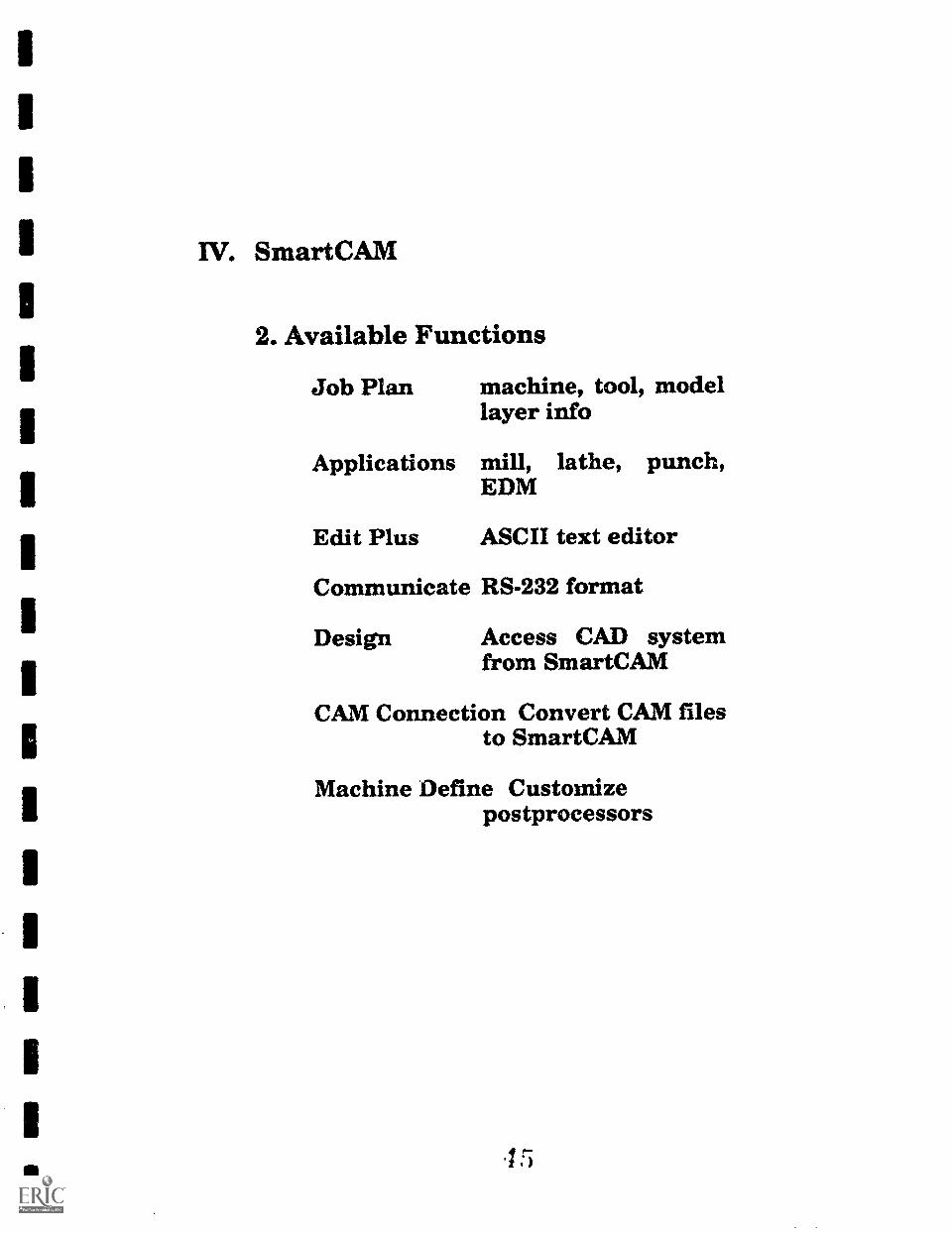
W. SmartCAM
2. Available Functions
Job Plan machine, tool, modellayer info
Applications mill, lathe, punch,EDM
Edit Plus ASCII text editor
Communicate RS-232 format
Design Access CAD systemfrom SmartCAM
CAM Connection Convert CAM filesto SmartCAM
Machine Define Customizepostprocessors
15

W. SmartCAM
3. General Method of Use
a. Create/modify Job Plan file
b. Select Application
c. Construct geometry
d. Insert machining operations
e. Show path to review operations
f. Generate code
g. Download code to machine
h. Verify

IV. SmartCAM
4. User Interface
Graphical User Interface (GUI)
Mouse or Keyboard input
Workplace Environmenttop menu barworkbenchtoolbox
- list viewcontol panel/dialogue boxgraphic window
Hot Keys
Screen Layout
Exercise I: Existing Model

Hot KeysSinutCAM Hot Keys are fUOCtiOCI keys that carry out or set a mode of operation when you press them.SmanCAM provides the followthg Hot Key=
Hot Key
iF81
[Ese]tilLetterl
[Esense]
[Ak]+iteller]
tAlt1.(12, Or 3]
bJ
ESblftl+cfeb]
[A1t]+17111
Show_Path Keys
fAltI+{111
[Rome]
[End]
What it DoesEnables you to input a value et coordinate. Displays the FikSelect Dialogue Bon where appropriate.
Mans Snap On or Off in the Read-out Line.
Pulls down the Workflane Me=
Redisplays the last dlaLgue hos.
Pulls down the View Menu.
Pulls down the Utility Menu.
Displays data for a selected element (works the same asElenent_Dsta in the Vzw Menu).
Redraws the semen (works ( he same as Redraw in the ViewMenu).
Selects e modeling tool in a toolbox. [Letter] should be the firstletter of the modeling tool you want. Press [Ese] and des[Letter) key at the same time.
Reams you to the Re Mew from anywhere in Smarr...AM.Press [Er) tyke in mom=Selects a pull-down menu ham the menu bac [Letter] should betheMt ler:of *Apt:II-down mmu you mei to display. Press[AM and the [Letter) key st the sime time.
Opens die toolbox impeded hy the rimed amber on theworkbench. Press [Alt] and the number key at the same thre.
Advances to the next control panel field.
Moves beck me control panel field.
Redraws dialogue boxes and control panels.
The following keys am operaticsal in Show...Path:(Enna] Quits Show_Path.[Ese] Stops Show_Path so that you can change Show_Path speed.
151 Starts Show_Path.
Provides help for the Ceinelit menu item, toolbox, control panel.dialogue ben or modeling tool.
Posideas to the top of a li Weill in Insert position.
Positions to the bottom of a list. Useful in Insert position.
Reproduced with permission of Point Control Co.

Graphicview
Normal text showsevallsbie options
Dim is4 showsoptions that amnot svslithie
Ala wt Cm*. Wes Iltit liarkflaie
Top Menu Bar
1
liacroOmar!Group
I Orasetry2 elo Cd it3 Orderjatis
0 lel'oraAfter
inemant.,,eTrofilkAmil
Leger..,9egOilletck 2lat
WO Iasi11
a
Nur thiplast: aiiitis hot: I Pt Ii Job Flee
GOMM Level: 9ibrkjiass: XigiteM char: 010a
Orfsetj Lett 1 Tool M ee* ProfJap: rme Efts! SmartCAM screen 1\
Control Penal/Dialogue Box
Workbench
Toolbox
Reproduced with permission of point Control Co.
.19

IV. SmartCAM
5. Preparing to Write a Program
Communicate informafion about thepart to be machined, the tooling, andthe setup to the CNC machineoperator.
a. Plan the setup
b. Plan the tool path
c. Select tools
d. Select speeds and feeds
5 0
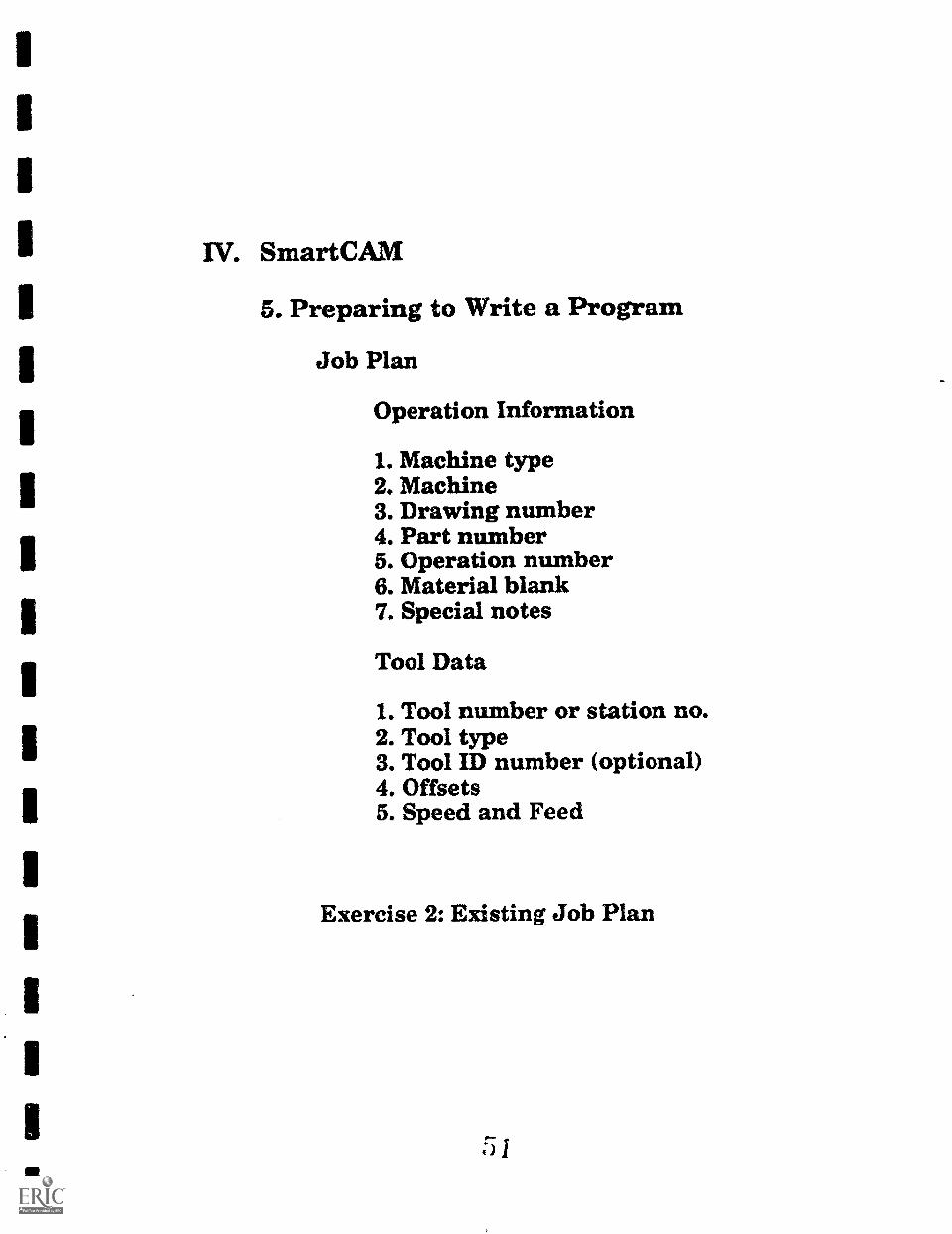
IV. SmartCAM
5. Preparing to Write a Program
Job Plan
Operation Information
1. Machine type2. Machine3. Drawing number4. Part number5. Operation number6. Material blank7. Special notes
Tool Data
1. Tool number or station no.2. Tool type3. Tool ID number (optional)4. Offsets5. Speed and Feed
Exercise 2: Existing Job Plan
51

III
W. SmartCAM 1
I6. Process Modeling
Milling (2 1/2 D) Io Geometry creation features Io Geometry edit features Io Verification features
1
II
Exercise 3: Free form geometryIExercise 4: Profile geometry
IIIIII
r;.)i,,,,1

IV. SmartCAM
7. Generating CNC Code
Job Plan information
Shape Database
Machine File
Template File
Exercise 5: Generate Code
I.
i 3

JOB PLANUSM6ADATAVilename.JSF
MACHINE FILE1SM6ISMFlmachlne.SMP
['SHAPE DATABASE -)1SMEADATAVilename.SHX
ACTUAL TOOL PATH
[TEMPLATE FILE\SM61SMFNmachine.TMP
[NC CODE FILE1SM6DATAVIlenarne
Flies used for Code Generation
Reproduced with permission of Point Control Co.

W. SmartCAM
8. Editing Code
Edit Plus text editor
Exercise 6: Generate codeModify job planGenerate code againView both filesNote differences

APPENDIX A: PART DRAWINGS
5 f;

an as me as Rim ow as =I No am am an IN um on me
0 250 x 90* DETENTS5 PLACES 0 266 THRU
CHORE 0 .4375X .350 OP.4 PLACES
0 .50 x 200FULL DEPTH
450
-1 1.00 I--A A
WIT Ma WILED MSSHOES MMUSam Imam gam
± .12110111
ME BC
ANGULAR
DO NOT SCALE
* .01.005l
MC-1234-A SHIFT PLATEPART NUMBER PART NAME
1/Point Control Co.(503)344-4470
DRAWN By! G. WITTLOCK
SCALE! NONE
MATERIAL! ALUMINUM
DATE! 7-24-91
5 7 5

RO 50
NM 1111111 OM nil MN NMI NMI MR NMI In NM INS
le/Point Control Co.(503)344-4470
BEGINING EXAMPLEGl̀i
as ail I Lim#111111 lin
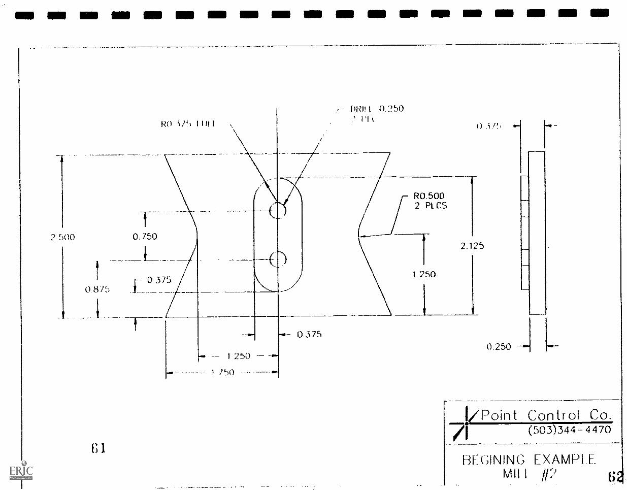
MI MI MI NM MO MI IMO NMI OM MN MN MIR IIMII OM EMI IMO
2.500
RO if) I 1111
1 P)()
I/Point Control Co.(503)344- 4470
BEGINING EXAMPL EMil I

3 8750
R3 0000
t;3
9 8750 -9.9375 5 5000
6.8750 --1 2 PL C
6.1875
0R41.500
R8 7500
INN MI IN MI NM
4.0625
0 6675
R16.5000
R1 0000
4.12507 1250
13'
RO 5000
MB ME NMI NM Mil
R1.5000
2.0000
3
I/Point Control Co.71
(503)344-4470
BEGINING EXAMPLE11115 P IRV I Mk la .110
III MI OM 11111111 OM MIS I= MI NM MIN MI MIN MN Ohm IIIII
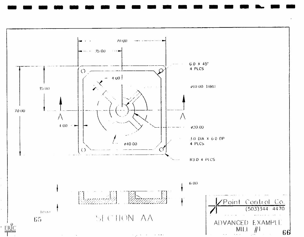
10 00
5!) 00
1
h)(h)
4 00
6 0 X 45'4 PLCS
oi0 00 IHRu
020 00
.50 DIA x 6 0 nr)040 00 4 PLCS
11, ,/ /7
. 'Ut7/:Ta 7
-)N AA
17Point Contr ol Co(503).344- 4470
ADVANCED EXAMHIviHi # 1

R1.075-) 1YP.
RO.5755 YP.
67
IIINS N-- INN MI N NI NM MB MN INN INN NE
kPoin t Control Co.(503)344- 4470/I
ADVANCED EXAMPLE=WON

MI OM MI IMO NIB MIN MO UM ME MI 111111 MI ill ME MIN 11111 IMO IIIII
1.250
R0.500
30"
2.250 --3,183
4.500
5.625
6 9
02.500
03.000
04.000
1/Point Control Co.7i (503)344-4470
BEGININC EXAMPLEATHE 111 70

R0 125
45 X ü 125
71
10.500
10 000
- 0,8120 375
165'
-11..
1/4 - 20 X .50 DP,
0.0625 X 45*5/8 - 11
0.125
MIS IMO MIN IMP MB INN NMI INN INN Mil 1E1
kpoint71
ADVAN(.11RIM aMi
Control Co.(503)344-4470
) LXAlvli'LL-1 ppm //jos me

-- N Ell NMI MI MI On IIIII nill an Inn OM lin En en NM lin OMB 11111 an

Hot KeysSmaitCAM Hot Keys are fimction keys that carry out or set a mode of operation when you press them.
SinartCAM provides the following Hot Key=
Hot Key
[n][F3]
[Fig
EF6/
[F7)
inl
[Ese3+[I-etter]
Pisalfsel
[AltHletter]
EA1041,2, or 31
What it DoesEnables you to input a vake or =ordinate. Displays the FileSelect Dialog= Box Mum appropritte.
Thms Snap On or Off in the Read-out Line.
Pulls down the Working= Mew.
Redisplays the last dialogue box.
Pull; down the View Menu.
Pulls down the Utility Menu.
Displays data for a selected element (works the same asElement_Data in the View Menu).
Redraws the sawn (works the same as Redraw in the ViewMenu)Selects a modeling tool in a toolbox. [Letter] should be the firstle= of the modeling tool you want Press [Esc] and the[Letter] key at tbe same time.
Retums you to tbe File Mew from anywhese in SmartCAM.Press Mae] twice in seipsznce.
Select a pull-down menu from the menu bar. [Letter] sts,ould bethe fiat letter of tbe pull-down nu= you wam to display. Press[Alt] and the [Letter] key at the same time.
Opens the toolbox preceded by the selected mmtber on thewaddles& Press [Alt] and the number key at the sante *me.
Advances to the next control panel field.
Moves back one control panel field.
Redraws ,lialogue boxes and comrol panels.
The following keys are operational in Sbowjatlx[Ese]lEse] Quits Showjath.[KW Stops Show_Path so that you can change Show...Path speed.
ES] Starts Show.Path.
Provides help for the cunent menu item, toolbox, control panel,dialogue box or modeling tool.
Posidons to the top of a list. Useful in Insert poskion.
Positions to the bouom of a list Useful in Insert position.
bJ
[Shift]+[Tab]
[Alt]+En]Show_Fath Keys
1A1044}11
[Home]
[End]
Reproduced with psrmission of Point Control Co.
7 4
A-6 Interacting with SmartCAM

,
I
-
.
PLC BASICS
Developed byGerard lnsolia
Center for Business and IndustryNorthampton Community College
3835 Green Pond RoadBethlehem, PA 18017-7599
75

PLC BASICS SEMINAR OUTLINE
1. WELCOME AND PERSONAL INTRODUCTION
2. WHAT IS A PLC?
3. HISTORY OF THE PLCA. ORIGINB. ORIGINAL INTENT OF THE PLCC. FLEXIBILITY AND SIMPLICITYD. ARE PLC'S COST EFFECTIVE?E. WHEN, WHERE, HOW AND WHY
4. BASIC COMPONENTS OF A PLCA. CENTRAL PROCESSING UNITB. POWER SUPPLYC. I/0 SYSTEM
5. LOGICAL FORMATA. HAND LOADERS, CRT'S, DATA LOADERS AND PC'S/PC SOFT
WAREB. LADDER LOGICC. STATEMENT LOGICD. STRUCTURED PROGRAMMING
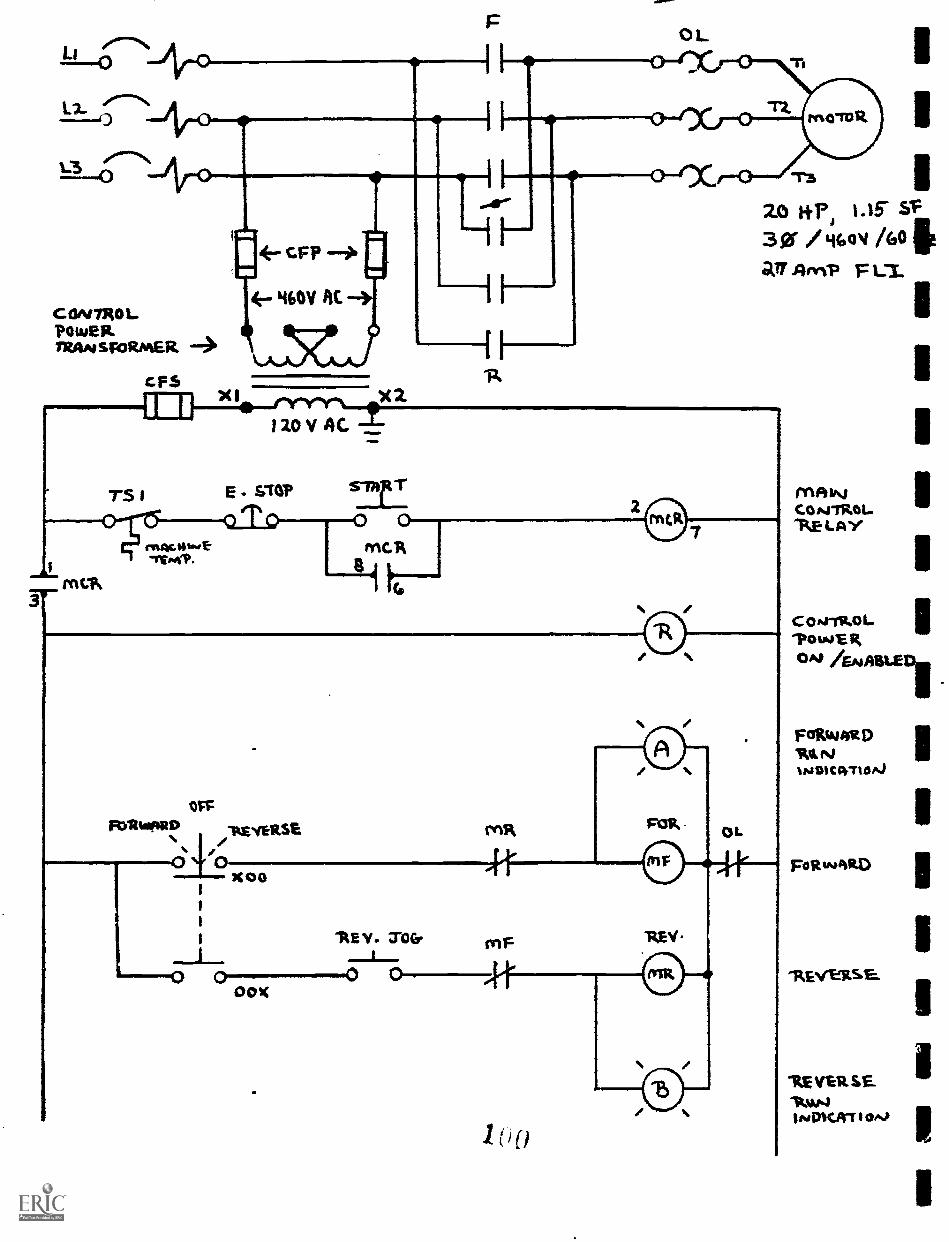
6, REVIEW OF BASIC CONTROL CIRCUIT DIAGRAMSA. RELAY LOGIC EXAMPLESB. PLC WIRING DIAGRAM EXAMPLEC. PLC LADDER LOGIC EXAMPLESD. PLC STATEMENT LIST LOGIC EXAMPLES
7. EMERGENCY STOP AND SAFETY CIRCUIT CONTROL
S. ELECTRICAL NOISE PROBLEMS AND POTENTIAL SOLUTIONS
9. PLC APPLICATIONS AND EXAMPLES
10. QUESTION AND ANSWER
NOTES:
OVERHEAD SLIDES WILL BE UTILIZED
UTILIZE HANDOUTS SUCH AS THE WESTINGHOUSE PLC ARTICLES ANDTHE PLC EXPERT EXAM
INTERACTION WITH THE CLASS WILL BE ENCOURAGED
76

II CAPABILITIES
IWhat is a PLC?
I Basics:
I I/0 Interfaces
iMemoryIProcessorIProgramming Language & Device
Power SupplyIHousings1
IIIIIIII 7 7
I
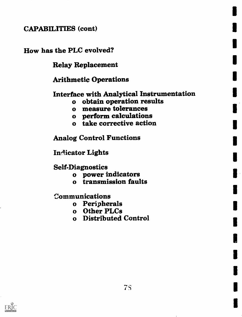
CAPABILITIES (con°
How has the PLC evolved?
Relay Replacement
Arithmetic Operations
Interface with Analytical Instrumentationo obtain operation resultso measure toleranceso perform calculationso take corrective action
Analog Control Functions
In4icator Lights
Self-Diagnosticso power indicatorso transmission faults
communicationso Peripheralso Other PLCso Distributed Control
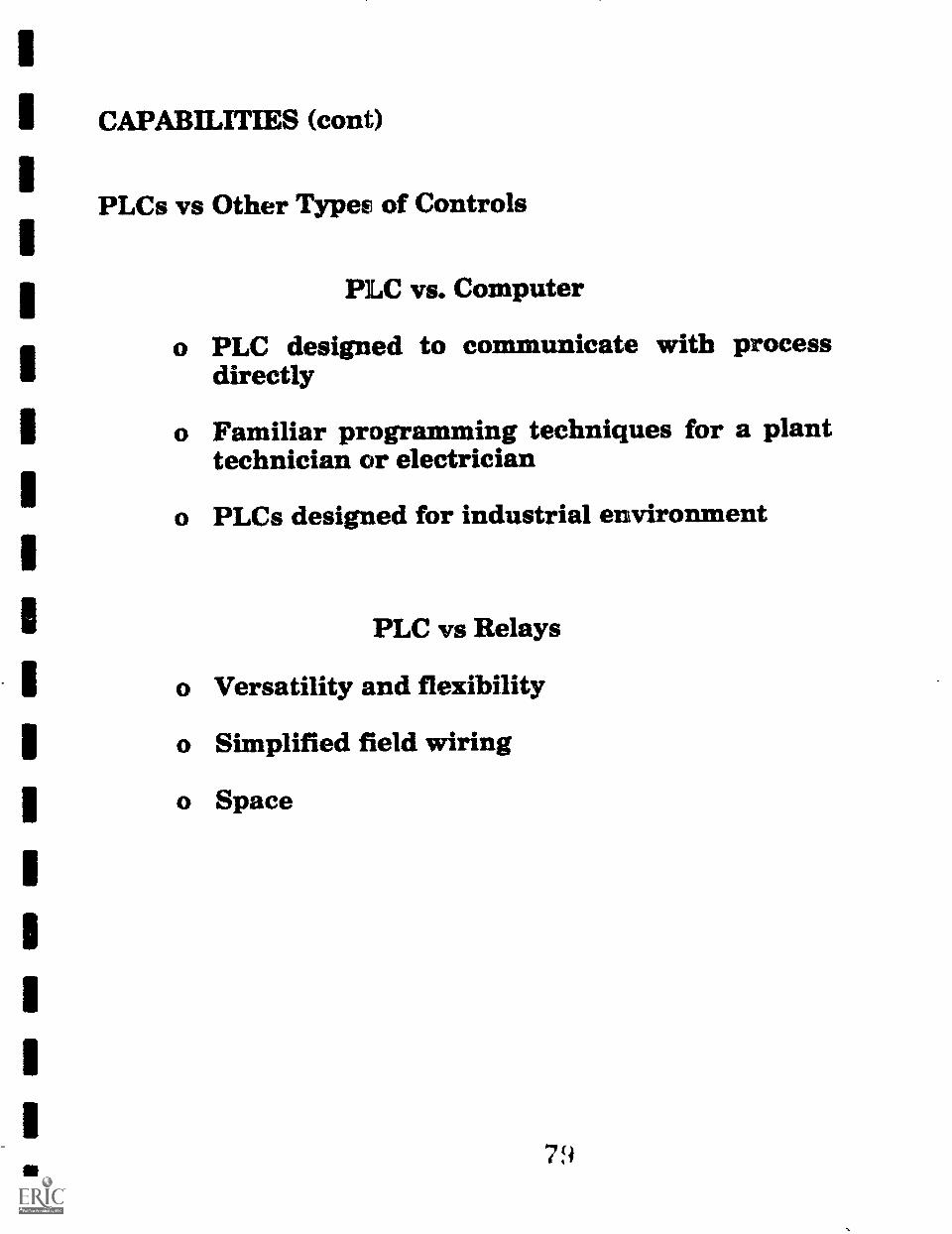
II CAPABILITIES (cont)
IPLCs vs Other Types of Controls
1
I PLC vs. Computer
I o PLC designed to communicate with processdirectly
1 o Familiar programming techniques for a plant
Itechnician or electrician
o PLCs designed for industrial environment
II PLC vs Relays
I o Versatility and flexibility
1 o Simplified field wiring
1 o Space
IIII1
79I

SELECTION CONSIDERATIONS
System Attributes
1. I/0 Requirements
o Number of I/O points
o Types of I/0Discrete or analogAC or DC AC: 24V, 115V, 230V
DC: 5V, 12-30V
o Special FeaturesHigh speed inputsServo drive moduleThermocouple moduleCommunications
o Location of I/ODistributed controlRemote I/0

SELECTION CONSIDERATIONS (cont)
2. Memory Requirements
o Type
Capacity
o Allocationprogram areaexecutive programsdata table area
3. Programming Requirements
o Instruction Set
4. Peripheral Requirements
o Programmero Printero Modemo Computer

SELECTION CONSIDERATIONS
How Cost-Effective are PLCs?
Factors
o Purchase price
o Installation costs
o Throughput
o Machine system safety
o Versatility
o Downtime and repair costs
o System power consumption
o Expandability
o Longevity
IIII1
IIIIIIII1
II
52 1
II

APPLICATIONS
1. Bulk Material Handling
Fiberglass production at PPG Industries
System Description
o Raw ingredients weighed, mixed, transported
o Batch fed continuously into furnaces
Control Strategy
o Hierarchical control system
o 3 independent subsystems
o semi- or fully- automatic operation
1
S 3
1

1. Bulk Material Handling (cont)
Fiberglass production at PPG Industries
Implementation
o Activated incrementally
o Distributed control with 20 PLCs
o Supervisory PLC coordinates operation andcontrols batch system
o Redundant precossor and power supply
o Process computer performs monitoring,alarming, logging functions
Results
o System replaces two operators

3
APPLICATIONS
2. Controlling Heat Treating Ovens
General Electric Company
System Description
o Rail car loaded with six 30,000 pound ingots isrun into the oven
o Oven brought up to Temp1 and maintained
1o Temp dropped at controlled rate until Temp2
o Cycle repeated four times
Control Strategy
o Oven divided into three segments, six zones
o 1 sensor for each segment
1o 2 secondary sensors for each segment
1
S 5

2. Controlling Heat Treating Ovens
General Electric Company
Implementation
o Combustors fueled from motor driven valves
o 2-speed circulating fans distribute heat
o One PLC controls oven temp, valves, fansf
o Pm control used to minimize temperaturefluctuations
Results
o Large energy savings due to accurate control

APPLICATIONS
3. Packaging Food in Glass
FLOE Inc.
System Description
o Glass containers are fed, cleaned, filled, andcapped
o Containers are queued if necessary
o Containers are labeled, assembled into cases,and palletized
Control Strategy
o Variety of inputs suited to particular tasks
o Control conveyor speed for better filling
o Active accumulator to control supply to labeler

3. Packaging Food in Glass
FLOE Inc.
Implementation
o Proximity, photocell, and microswitch inputs
o All motor control sequenced by the PLC
o Accumidator conveyor driven forward orreverse, based on labeler load
o PLC counts each jar, cap, and label. Recordstime and count of all line malfunctions.
o Report generated showing efficiency of eachpiece of equipment on the line
Results
o Total line efficiency monitoring aidsmaintenance management
o Equipment replacement simplified

APPLICATIONS
4. Energy management
Seaboard Energy Systems, Inc.
Reducing electrical consumption and peak demand
o Monitor electric meter to pinpoint risingconsumption
1 o PLC shuts down predetermined equipment toavoid peak charges
Managing chillers
o Monitor chilled water in the loop, ambient temp,discharge and return temp, and chiller load
o Control difference between discharge andreturn water temps, units onloff line

4. Energy management (cont)
Seaboard Energy Systems, Inc.
Controlling boilers
o Monitor steam flow and steam pressure
o Increase/decrease the fuel flow as steampressure drops/increases
Controlling outside dampers
o Monitor outside air temp and return air temp
o Control amount of fresh air mixed with returnair to be heated or cooled
o Use motorized damper controls to open/close thedampers as temperature changes during the day
Results
o 10 to 20 percent reduction in energyconsumption and costs
1

APPLICATIONS
Industry Breakdown
AutomotiveUtilities and Oil RefineriesFood and BeverageGlass, Rubber, Plastics, Chemicals, Paper,Agricultural and Engineering Products

OL.
CONTROU441u414.filivaSfORPIER
CPS
v
-rws
20 00 13i sc3g *WI AO tiearl Arn?

eTh
CON7ROLPOtue R.nt4A/SFOR"Eit
CFS
ir3
26 1+134 1.15. sf3 01 "Go/far/4ml)
xi
3
13
IVAN_Car4TiLeit.-KeLAY
comiscol.-potwenov Awaits)
0,40N
""--
jr1k,%.,
CIL
CONTROLPOusela.TRANSFORmER
"r3
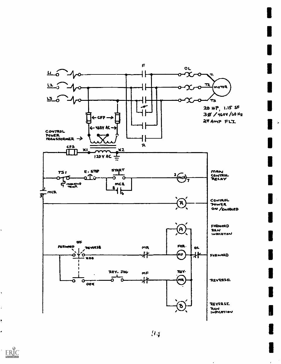
20 two 1-if SC39f itov Act owair /amp F LT.
T5 1 E. slop0 kictiDswamilbseaft%
3
mv. 7
4111:
FORwitt) .wwwtsa
BR V. TOC.
retR CL
0,444.41.44 41:1
RV.
4-r
MAINCap.:TRW-'RELAY
COorrIkOL
0.4 itENROLED
FORW4t0'RtImucirno.4
Foga"RD
"REV'EaRSS.
VER SElittm4
im WART I 0.40
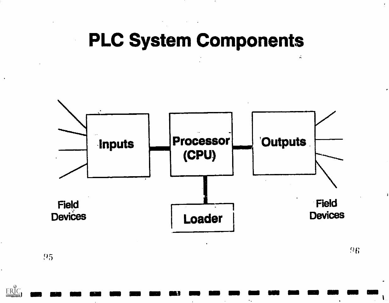
PLC System Components
mommlMENIMPI=1
FieldDeviaes
Inputs Processor(CPU)
rLoader
'Outputs
NField
Devices
ME IIIN MIS NM NM NIB IMO INS l NM MIMI -- MN 111111 MI NM MEI MI MIN

Ell NM IIIII UN NM IMO MN Ili all Ell OM NM IMP ON MINI MS MI MIN
rClOpen Start0 0
ose Stop
0
I/0 Example
/-\ Horn
A./ \,.....Control Panel
) 7
Level
I
I
Tank
I
9 8

IIIIIIII
,....-..NLI.0
p0 L
L311110 'T3
2-0 ffi'l 11-15- SF
30 / 4410'4 /GO He
aTI ArYVP F UL
C ON TRO L?OWE RTRAN s FORMER
CF5
)'X l
laoy AC.
T5 1 E . STOP Sly T
-0 ir 0 0 0-1MAC. Wiuwe
1 G
IIIII1
II 99
NIA ifyCONIIROL'RELAY
C 0 NIRO L*110 to E It
°N /ENABLED
Li
Aro..L3
CON 7RO L.?OwEP.IRAN sfoRmER --->
F $Xi
F
411=0.4
TS I
TrnsticiOsiat"MAT.
..=111IonIVR,
3T
X2120 4C
Flaltutpito4/14.EveltSE ml;#0
'coo kI
'RE V. MKT onF
0 000.
L
10 ktr 1.15 SF
30 /44ov AO 111
ag SIMI) FLL
MAINCo Arnt.W..-RE 4_ Ay
C o wrikoTowE
FaltwaRDRAN11NDIC4TIOA.)
FoRsAARD
"REVEll.sa
1tE VERSE14u4INDicirr 0A,
1
3 1

EVALUATION CHART
DESIGN TO MANUFACTURE
INISFACE
PERFORMANCE
CNC PARAMETERS
LOGICAL SEQUENCE
ESCAPE PROCEDURE
FILE STRUCTURE
SYSTEM THRU-PITT
CAD BMCNA BASED
CAM/CAD NED
EDIT CODE
EDIT GEOMETRY
EDIT PARAMETSIS
DIRECT CV NTRFACE
INDIRECT CAD INTERFACE
GENERIC POST
CUSTOM POST
USER SUPPORT
COST W/O CAD
CAD ADDL COST
POINT VTAIS
COST
SYS A MS B SYS C
iNWS!O OPMMMIMimm
OMMINMAD WMNI .=111Ma m4In
OW.14M
AMMNIMPIMNIN 41 ME.Im
aMEM.M
W MMIMmW.M.WwWNoi 11M=.16 ==11!
ammMMIMMm
itig.~1 MIWIIMMMMMIID mPNIM. IMMMEril XX
M=MMEMIIP4IM MM=m
=MM AMM=M
1111 .1IMMN .1.111
IPPIMMEN111111111, 1
Reproduced with permission of RERTC
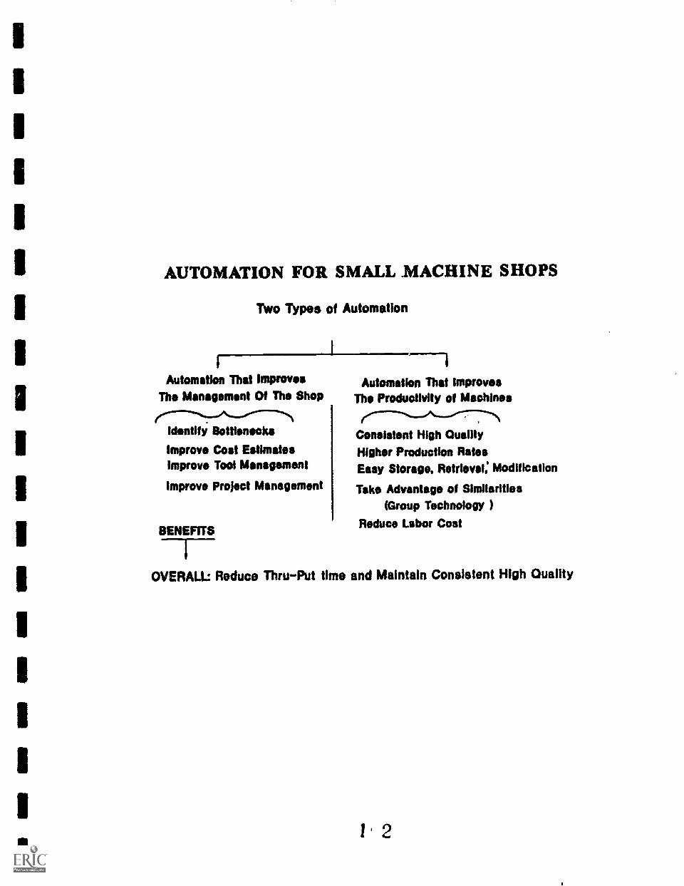
AUTOMATION FOR SMALL MACHINE SHOPS
TWo TYpes of Automation
Automation That ImprovesThe Management Of The Shop
Identify Bottlenecks
Improve Cost Estimatesimprove Tool Management
Improve Project Management
BENEFITS
Automation That ImprovesThe Productivity of Machines
Consistent High QualityHigher Production RatesEasy Storage, Retrieval: Modification
Take Advantage of Similarities(Group Technology )
Reduce Labor Cost
OVERALL: Reduce Thru-Put time and Maintain Consistent High Quality

Costlot lost Ion
ProcuresMont,*
SHOP of the 90's CONFIGURATION
1111shop FloorProgroolos
MIN11111 I
1
$lug FloorProvost no
Lan
1

Ratinitignatmatatimmairainenta
I Part analysis. Page
A. Part description.B. Quantity/Part cycle.C. Projection for future.
II CNC machine tools.
A. Machina tool types.8. Machine tool description.C. Controllers.D. Program transfer.E. Projection for future.
III CAM requirements.
A. Part complexity.B. Macro capability.C. Parametric programming.D. Communication files.E. Operating system(s).
IV CAD system(s).
A. In-Nouse requirements.B. Communication files.C. Operating system(s).D. hardware.E. Projection for future.
V WorXforce.
A. Engineering/Drafting.B. CAD knowledgeable.C. CAN knowledgeable.D. Projection for future.
Reproduced withpermission of NEMTC
1 4

II CNC Machine tools.
A. Machine tool types.
1. Milling.
a. 2 axis.
b. 3 axis.
c. 4 axis.
d. 5 axis.
2. Turning.
3. Electrical discharge.
a. Solid.
b. Wire.
4. Grinding.
a. Surface.
b. Cylindrical.
5. Laser.
6. Router.
a. 3 axis.
b. 3 axis.
7. Punch.
awl111.11!
ONNI
O. Coordinate measure. #
Roproducod with permission of NENTC

B. Machine tool description.
1.
2,
3.
4.
5.
6.
C. Controllers.
1.
2.
3.
4.
5.
6.
D. Program Transfer.
1. Tape/disk transfar.
2. Direct connect.
3. Local netwrk.
E. Projection for future.
Reproduced with permiesion of NEM=
I fi

5. CATIA (IBM). y N
4. GDF (ISM). Y N
7, CADAM. Y N
8. MPGL (Hewlett-Packard). Y N
9. CGM (Computer graphics Metafile). Y N
10 NFL (Anvil). Y N
E. Operating aystem(s).
1. PC-Dos/MS-Doe.
2. UNIX.
3. Macintosh.
4. Other.
Reproduced with permission of NEKTC
Y N
Y N
Y N

1
1
1
/V CAD systam(s).
A. In-house requirements.
1. Design and drafting of parts.
2. CAD %used for transfer to CAM.
3. CAD used for detailed drawings.
B. Communications files.
1. EMI (Ansii for MAPICS).
2. DXF (AutoCAD).
3. IGES. (universal).
4. CADL (CadKEY).
5. CATIA (ISM).
6. CD? (IBM.
7. CADAM.
S. VOL (Hewlett-Packard).
9. COM (Computer graphics Metafile).
10 NFL (Anvil).
C. Operating syetem(s).
I. PC-Dos/KS-Dos.
2. UNIX.
3. Macintosh.
4. Other.
Reproduced with permission of NEHTC
S
Y N
Y N
Y N
Y N
Y N
Y N
Y N
Y
Y N
Y

D. Hardware.
1. Microprocessor/Co-processor.
a. XT 8088/8087 processor. 0
b. AT 80286/80287 processor. 0
C. AT 80386/80387 processor. 0
d. Macintosh. 0
e. Other. 0
2. Display device.
a. 12" monochrome/color. 0
c. 14" Nonochrome/color. 0
e. 16" or larger color. 0
2. Input devices.
a. Digitizer.
b. Muse.
3. Plotter
4. Scanner.
E. Projection for future.
Reproduced with permission of Nom
I (
0

V Workforce.
A. Engineering/Drafting.
1. Employees working as Design engineers .
2. Employees working as Production engineers.
3. Employees working as manual drafting.
B. CAD knowledgeable.
1. Employees working as CAD drafting/design.
2. Employees working as CAD drafting/update.
3. Employees working as CAD drafting/transfer.
C. CAM knowledgeable.
1. Employees working as CNC programers.
2. Employees working as CAM programmers.
=WOO
.111.0M
ImENW!
E. Projection for future. (yes no months)
1. Train manual programers for CAN. Y N Ks
2. Train CAD programers for CAM. Y N Ms
3. Hire additional CAN programmers. Y N Ms
4. Train manual draftperson for CAD. Y N Ms
5. Hire additional draftperson for CAD. Y N Ms
5. Additional comments:
Reproduced with permission of MCC
It 0

Part analysis.
II CNC machine tools.
IIT CAN requirements.
IV CAD requirements.
V Workforce.
Repi-oduced with permission of WENTC