eddy fire hydrant...eddy fire hydrant the eddy hydrant is a classic design built to provide...
TRANSCRIPT

Clow Valve is a division of McWane, Inc.
• SINCE 1875
ClowValve.com
EDDY FIRE HYDRANTMODEL F-2640 / F-2641AWWA C502 • UL LISTED* • FM APPROVED • 250 PSI RATED • BOTH DRAIN AND DRAINLESS FEATURES AVAILABLE • 10-YEAR LIMITED WARRANTY • SAME RELIABLE DESIGN SINCE 1875
*5 1/4 ONLY UL/FM

EDDY FIRE HYDRANTThe Eddy hydrant is a classic design built to provide unsurpassed fire protection and an appealing aesthetic. Since 1875, the Eddy hydrant has been reliably serving communities and firefighters across the country.
The Eddy opens easily and quickly under pressure, ensuring time-tested performance year after year.
HYDRANT VALVE SIZE D
4 1/2 6 1/4
5 1/4 7 1/16
RISING STEMIndicating feature lets you know position of main valve.
INDEPENDENT DRAINAllows plugging of drain without disassembly of hydrant.
BREAK FLANGE DESIGNBreakaway parts shear cleanly above the barrel, reducing nozzle section damage or opening of the main valve.
STEM NUT BELOW GROUND LINEMaintains positive shut off of main valve after traffic damage. Does not depend on water pressure. Never needs lubrication. All copper alloy construction.
MAIN VALVE OPENS WITH PRESSURE
Water assists in opening the valve, making operation easier,
faster, and positive.
MAIN VALVE CLOSES AGAINST PRESSURE
Reduces valve seat damage and lowers the potential
for water hammer.
THREADED NOZZLESEasily replaced locking set screw to
hold nozzle in place. O-ring seal.
ENGINEERING FEATURES

D
5
6
7 8
4
3
2
1
17
18
9 10 11 12
14
15
21
16
13
1920
22
25
26
23
24
27
28
3130
29
32
33
34
35
3637
3839
31
40
4142
43
44
45
46
49
4748
5150
AA
BB
C
RECOMMENDED SPECIFICATIONS
1. Hydrant shall be center-stem type and in accordance with AWWA Standard C502.
2. Hydrant shall be compression type with the main valve opening with the water pressure and have a rising stem to positively indicate open or closed position.
3. Hydrant shall be furnished with frangible flange and stem coupling at the ground line. Frangible bolts available upon request.
4. Copper alloy stem threads shall be located below the main valve to eliminate necessity of lubrication; main valve will remain mechanically closed in case of damage to hydrant.
5. Hydrant shall have minimum valve opening of either 4 1/2” or 5 1/4”; shoe inlet of 4” or 6”.
6. Hydrant shall be designed to permit removal of all working parts without special tools or wrenches.
7. Hydrant shall be the Eddy hydrant, manufactured by Clow Valve Company.
EDDY HYDRANT PARTS ASSEMBLYWITH DRAIN ASSEMBLY
F-2640
PART NO. DESCRIPTION MATERIAL QTY.
1 Hold Down Bolt Stainless Steel 1
2 Operating Nut Cast Iron 1
3 Packing Gland Copper Alloy 1
4 O-Ring w/ Adapter Optional 1
4 Packing Rubber 1
5 Cover Bolts & Nuts Stainless Steel 8
6 Cover Cast Iron 1
7 Flange O-Ring Rubber 2
8 Swivel Ring Cast Iron 1
9 Hose Nozzle O-Ring Rubber 2
10 Hose Nozzle Copper Alloy 2
11 Hose Noz. Gasket Neoprene 2
12 Hose Noz. Cap Cast Iron 2
13 Steamer Nozzle O-Ring Rubber 1
14 Steamer Nozzle Copper Alloy 1
15 Steamer Nozzle Gasket Neoprene 1
16 Steamer Nozzle Cap Cast Iron 1
17 Nozzle Section Cast Iron 1
18 Nozzle Section O-Ring Rubber 1
19 Break Flange Bolts & Nuts Yellow Zinc Steel 8
20 Break Flange Cast Iron 2
21 Standpipe Ductile Iron 1
22 Bottom Bolts & Nuts Stainless Steel 8
23 Bottom O-Ring Rubber 1
24 Seat Ring Copper Alloy 1
25 Drain Cup Copper Alloy 1
26 Hydrant Bottom Ductile Iron 1
27 Hydrant Bottom Nut Copper Alloy 1
28 Retaining Clip Stainless Steel 1
29 Upper Stem Steel & Copper Alloy 1
30 Stem Coupling Cast Iron 1
31 Stem Coupling Pins Stainless Steel 3
32 Middle Stem Steel 1
33 Lower Stem Copper Alloy 1
34 Valve Plate Cast Iron 1
35 Valve Rubber Rubber 1
36 Thrust Washer Copper Alloy 2
37 Lower Stem O-Ring Rubber 2
38 Snap Ring Stainless Steel 1
39 Throttling Ring Copper Alloy 1
40 Retaining Nut Copper Alloy 1
41 Drain Valve Rubber Rubber 1
42 Drain Valve Backer Copper Alloy 1
43 Drain Rod Steel 1
44 Clevis Nut Copper Alloy 1
45 Drain Support Cast Iron 1
46 Lever Pin Copper Alloy 1
47 Clevis Copper Alloy 1
48 Cotter Pin Copper Alloy 2
49 Drain Lever Copper Alloy 1
50 Drain Spool Copper Alloy 1
51 Jam Nut Copper Alloy 1
Chain Zinc Plated Steel 3
WORKING PRESSURE: 250 PSI
ASSEMBLY CONSISTING OF PARTS
AA Main Stem 29-33
BB Hydrant Valve 34-39
C Drain Support 44-49
D Drain Valve 40-43, 50-51
EE Complete Valve and Stem Assemblies AA & BB
BB
19
5
6
7 8
4
3
2
1
30
18
9 10 11 12
14
15
21
1617
13
20
22
25
23
24
2627
3029
28
31
32
33
34
3536
3738
AA
RECOMMENDED SPECIFICATIONS
1. Hydrant shall be center-stem type and in accordance with AWWA Standard C502.
2. Hydrant shall be compression type with the main valve opening with the water pressure and have a rising stem to positively indicate open or closed position.
3. Hydrant shall be furnished with frangible flange and stem coupling at the ground line.
4. Copper alloy stem threads shall be located below the main valve to eliminate necessity of lubrication; main valve will remain mechanically closed in case of damage to hydrant.
5. Hydrant shall have minimum valve opening of either 4 1/2” or 5 1/4”; shoe inlet of 4” or 6”.
6. Hydrant shall be designed to permit removal of all working parts without special tools or wrenches.
7. Hydrant shall be without a drain to prevent the possibility of cross connection.
8. Hydrant shall be the Eddy hydrant, manufactured by Clow Valve Company.
F-2641EDDY HYDRANT PARTS ASSEMBLY — NO DRAINFOR PROTECTION AGAINST CROSS CONNECTION
PART NO. DESCRIPTION MATERIAL QTY.
1 Hold Down Bolt Stainless Steel 1
2 Operating Nut Cast Iron 1
3 Packing Gland Copper Alloy 1
4 O-Ring w/ Adapter Optional 1
4 Packing Rubber 1
5 Cover Bolts & Nuts Stainless Steel 8
6 Cover Cast Iron 1
7 Flange O-Ring Rubber 2
8 Swivel Ring Cast Iron 1
9 Hose Nozzle O-Ring Rubber 2
10 Hose Nozzle Copper Alloy 2
11 Hose Noz. Gasket Neoprene 2
12 Hose Noz. Cap Cast Iron 2
13 Steamer Nozzle O-Ring Rubber 1
14 Steamer Nozzle Copper Alloy 1
15 Steamer Nozzle Gasket Neoprene 1
16 Steamer Nozzle Cap Cast Iron 1
17 Nozzle Section Cast Iron 1
18 Nozzle Section O-Ring Rubber 1
19 Break Flange Bolts & Nuts Yellow Zinc Steel 8
20 Break Flange Cast Iron 2
21 Standpipe Ductile Iron 1
22 Bottom Bolts & Nuts Stainless Steel 8
23 Bottom O-Ring Rubber 1
24 Seat Ring Copper Alloy 1
25 Hydrant Bottom Ductile Iron 1
26 Hydrant Bottom Nut Copper Alloy 1
27 Retaining Clip Stainless Steel 1
28 Upper Stem Steel & Copper Alloy 1
29 Stem Coupling Cast Iron 1
30 Stem Coupling Pins Stainless Steel 3
31 Middle Stem Steel 1
32 Lower Stem Copper Alloy 1
33 Valve Plate Cast Iron 1
34 Valve Rubber Rubber 1
35 Thrust Washer Copper Alloy 2
36 Lower Stem O-Ring Rubber 2
37 Snap Ring Stainless Steel 1
38 Throttling Ring Copper Alloy 1
Chain Zinc Plated Steel 3
ASSEMBLY CONSISTING OF PARTS
AA Main Stem 28-32
BB Hydrant Valve 33-38
EE Complete Valve and Stem Assemblies AA & BB
WORKING PRESSURE: 250 PSI

ALUMINUM BRONZE CLAPPER WITH RESILIENT SEAT
Threats to the water supply can come from either accidental or deliberate acts. Our nation’s water superintendents have safeguarded nearly all of the access points to our drinking water. At this time, one critical access point is left unprotected — the fire hydrant.
The Patriot hydrant check valve prevents reverse flow through the fire hydrant, safely protecting our drinking water while providing a full-port unobstructed waterway that allows firefighters access to the water they need when they need it.
Unlike locks and special external devices, the Patriot is installed underground, which prevents tampering and allows the hydrant to be operated the moment the firefighters arrive on the scene. The Patriot can be installed on any 6” mechanical joint connection, ensuring compatibility with all hydrant brands — providing the flexibility and cost-effectiveness you demand.
PATRIOT HYDRANT CHECK VALVEGUARD YOUR WATER SYSTEM FROM ACCIDENT OR ATTACK
RECOMMENDED SPECIFICATIONS (OPTIONAL)
1. The check valve shall be manufactured to all of the testing and performance standards of AWWA C508 and AWWA C550. The check valve shall be designed for 250 psi working pressure and tested to 500 psi hydrostatic pressure.
2. The check valve shall be a standalone unit able to be positively restrained to any 6” mechanical joint fire hydrant shoe.
3. The check valve shall be ductile iron ASTM Standard A536 (70-50-05), with NSF-approved fusion-bonded epoxy coating (interior/exterior).
4. The check valve shall be lead free, with no exposed lead-bearing surfaces.
5. The check valve shall have an unobstructed waterway. No reduction of port or redirection of flow will be allowed.
6. The seat shall be retained via a double dove tail o-ring, retaining groove design to ensure a positive seal.
7. The check valve shall incorporate integral positive restraint connections that maintain a restrained connection between the fire hydrant and the gate valve.
8. The check valve shall incorporate a stainless steel spring that hastens positive closure and prevents water hammer.
9. All fasteners shall be 304 stainless steel, and all interior rubber components shall be EPDM rubber.
10. The check valve shall be produced with no less than 80% post consumer recycled content while being cast, manufactured, assembled, and tested in the United States.
ClowValve.com
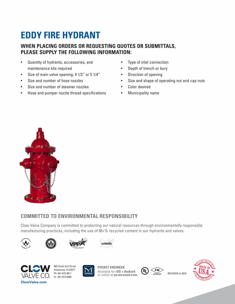
EDDY FIRE HYDRANTWHEN PLACING ORDERS OR REQUESTING QUOTES OR SUBMITTALS, PLEASE SUPPLY THE FOLLOWING INFORMATION:
• Quantity of hydrants, accessories, and maintenance kits required
• Size of main valve opening: 4 1/2“ or 5 1/4“• Size and number of hose nozzles• Size and number of steamer nozzles• Hose and pumper nozzle thread specifications
• Type of inlet connection• Depth of trench or bury• Direction of opening• Size and shape of operating nut and cap nuts• Color desired• Municipality name
902 South 2nd StreetOskaloosa, IA 52577 Ph 641-673-8611Fx 641-673-8269
COMMITTED TO ENVIRONMENTAL RESPONSIBILITY
Clow Valve Company is committed to protecting our natural resources through environmentally responsible manufacturing practices, including the use of 80+% recycled content in our hydrants and valves.
POCKET ENGINEERAvailable for iOS + Android or online at pe.mcwane.com. REVISION A-2019