edelbrock e-force supercharger - summit racing equipmentedelbrock e-force supercharger system 2014...
TRANSCRIPT
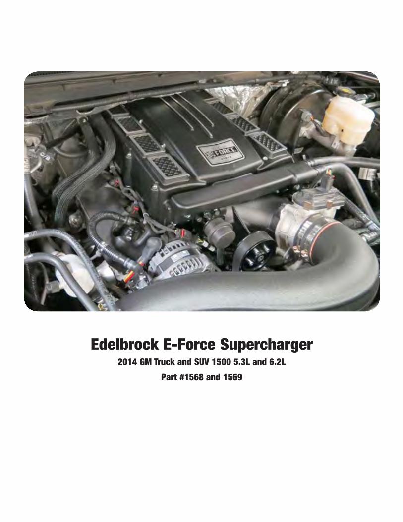
Edelbrock E-Force Supercharger2014 GM Truck and SUV 1500 5.3L and 6.2L
Part #1568 and 1569

©2015 Edelbrock LLCPart #1568, 1569
Brochure #63-1568Rev. 4/2/15 - QT
Edelbrock E-Force Supercharger System 2014 GM Truck & SUV 1500 5.3L and 6.2L
Installation Instructions
Page 1
Thank you for purchasing the Edelbrock Supercharger System for the 2014 GM 1500 Trucks and SUVs. This system utilizes the same Eaton Gen VI TVS Supercharger rotors as the previous E-Force supercharger but housed inside a redesigned supercharger manifold. Paired with bolt-on runners, this new package will fit under the factory hood with no modifications to the stock body or hood. The supercharger retains the inverted design which expels air upward. Air pressure then builds in the plenum, before being drawn down through the twin intercooler cores.
This system features a cast water crossover to simplify intercooler hose routing. The water crossover is secured to the manifold, allowing the cooled 50/50 coolant mixture from the LTR (Low Temp Radiator) to cool down the twin intercoolers housed inside the manifold.
The supercharger is 50-state emissions legal, and includes a 3-year 36,000 mile warranty so that there are no worries when installing it on a brand new car.
INTRODUCTION
TOOLS AND SUPPLIES REQUIRED z Jack and Jack Stands OR Service Lift z Ratchet and Socket Set including but not limited to: 7mm, 8mm, 10mm (standard, deep and swivel), 11mm, 12mm, 13mm and 15mm
z Breaker Bar: 1/2” z Allen Wrenches: 5mm, 6mm, 8mm z Torx Drives: T15, T30 z Panel Puller z Flat Blade & Phillips Screwdrivers z Coolant Drain Bucket z 50/50 Coolant Mixture (4.5 quarts) z Side Cutters
z Angle Grinder, or equivalent z 7/8” Fuel Line Removal Tools z Drill z 1-1/4” Hole Saw z Torque Wrench z Pliers OR Hose Clamp Removal Tool z Blue, Green and Red Thread Retaining Compound z O-ring Lube z Masking Tape z Shop Rags z Wire Ties

©2015 Edelbrock LLCPart #1568, 1569
Brochure #63-1568Rev. 4/2/15 - QT
Edelbrock E-Force Supercharger System 2014 GM Truck & SUV 1500 5.3L and 6.2L
Installation Instructions
Page 2
Due to the complexity of the Edelbrock E-Force Supercharging system, it is recommended that this system only be installed by a qualified professional with access to a service lift, pneumatic tools, and a strong familiarity with automotive service procedures. To qualify for the optional supplemental warranty, it is necessary to have this system installed by a Certified ASE Technician at a licensed business, GM Dealership, or an Authorized Edelbrock Installer. Failure to do so will void and/or disqualify any and all optional supplemental warranties offered with this system. Please contact the Edelbrock Technical Support department if you have any questions regarding this system and/or how your installer of choice will affect any warranty coverage for which your vehicle may qualify.
Proper installation is the responsibility of the installer. Improper installation will void all manufacture’s standard warranties and may result in poor performance and engine or vehicle
damage.Inspect all components for damage that may have occurred in transit before beginning
installation. If any parts are missing or damaged, contact Edelbrock Technical Support, not your parts distributor.
Any equipment that directly modifies the fuel mixture or ignition timing of the engine can cause severe engine damage if used in conjunction with the Edelbrock E-Force Supercharger System. This includes, but is not limited to: OBDII programmers, MAF sensors, adapters and any other device that modifies signals to and/or from the ECU. Aftermarket bolt-on equipment such as underdrive pulleys or air intake kits will also conflict with the operation of the supercharger and must be removed prior to installation. Use of any of these products with the E-Force Supercharger could result in severe engine damage.
Any previously installed aftermarket tuning equipment must be removed and the vehicle returned to an as stock condition before installing the supercharger.
Before beginning the installation, use the enclosed checklist to verify that all components are present in the box then inspect each component for damage that may have occurred in transit. If any parts are missing or damaged, contact Edelbrock Technical Support (800-416-8628), not your parts distributor.
WARNING: Installation of this supercharger will result in a significant change to the performance characteristics of your vehicle. It is highly recommended that you take some time to familiarize yourself with the added power and how it is delivered. This must be done in a controlled environment. Take extra care on wet and slippery roads as the rear tires will be more likely to lose traction with the added power. It is never recommended to turn off your vehicles traction control system.
IMPORTANT WARNINGS
©2015 Edelbrock LLCPart #1568, 1569
Brochure #63-1568Rev. 4/2/15 - QT
Edelbrock E-Force Supercharger System 2014 GM Truck & SUV 1500 5.3L and 6.2L
Installation Instructions
Page 3
It is recommended that you check the Edelbrock Tech Center Website for any updates to this installation manual. Please refer to the lower right hand corner to verify that you have the latest revision of this installation manual before beginning the installation.
Tech Center: http://www.edelbrock.com/automotive_new/misc/tech_center/install/index.php
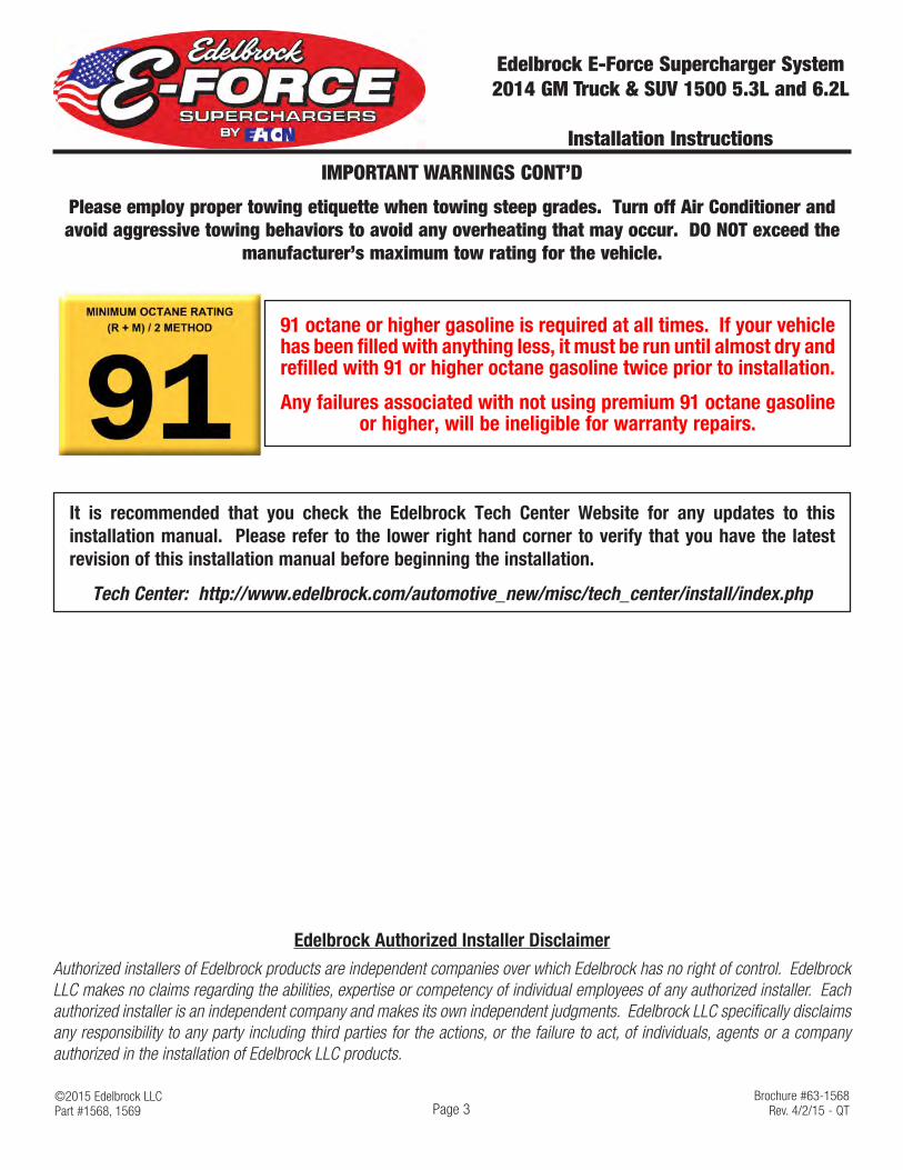
91 octane or higher gasoline is required at all times. If your vehicle has been filled with anything less, it must be run until almost dry and refilled with 91 or higher octane gasoline twice prior to installation.
Any failures associated with not using premium 91 octane gasoline or higher, will be ineligible for warranty repairs.
IMPORTANT WARNINGS CONT’D
Edelbrock Authorized Installer DisclaimerAuthorized installers of Edelbrock products are independent companies over which Edelbrock has no right of control. Edelbrock LLC makes no claims regarding the abilities, expertise or competency of individual employees of any authorized installer. Each authorized installer is an independent company and makes its own independent judgments. Edelbrock LLC specifically disclaims any responsibility to any party including third parties for the actions, or the failure to act, of individuals, agents or a company authorized in the installation of Edelbrock LLC products.
Please employ proper towing etiquette when towing steep grades. Turn off Air Conditioner and avoid aggressive towing behaviors to avoid any overheating that may occur. DO NOT exceed the
manufacturer’s maximum tow rating for the vehicle.

©2015 Edelbrock LLCPart #1568, 1569
Brochure #63-1568Rev. 4/2/15 - QT
Edelbrock E-Force Supercharger System 2014 GM Truck & SUV 1500 5.3L and 6.2L
Installation Instructions
Page 4
Bag #1
(1x) - M8 x 1.25 x 25mm Hex Flange
(1x) - M8 Washer
INSTALLATION HARDWARE IDENTIFICATION GUIDE (Parts Are Not To Scale)
(3x) - M8 x 1.25 x 130mm SHCS
(8x) - M6 x 1.0 x 10mm Hex Flange
(2x) - M8 x 1.0 x 16mm BHCS Flange(8x) - 3/4” Hose Clamp
Bag #2
(14x) - M6 x 1.0 x 90mm SHCS
Bag #3
(10x) - M6 x 1.0 x 85mm Hex Flange
(2x) - Grommet
Bag #4
(2x) - 10mm Quick Disconnect Fitting
(1x) - M10 x 1.5 x 200mm Stud
(1x) - M10 x 1.5 Nylon Insert Nut
(1x) - M10 x 1.5 x 40mm Hex Flange
(2x) - M10 Washer
(2x) - M8 Washer
(2x) - M6 x 1.0 x 20mm SHCS (1x) - .015” Taper Jet

©2015 Edelbrock LLCPart #1568, 1569
Brochure #63-1568Rev. 4/2/15 - QT
Edelbrock E-Force Supercharger System 2014 GM Truck & SUV 1500 5.3L and 6.2L
Installation Instructions
Page 5
BRACKET AND FEAD IDENTIFICATION GUIDE(Parts Are Not To Scale)
Water Pump Bracket
Water Pump Isolator
Smooth Idler Pulley (2)Grooved Idler Pulley
Large Spacer
Small Spacer
Upper / Driver LTR Bracket
Upper / Passenger LTR Bracket
Lower / Driver LTR Bracket
Lower / Passenger LTR Bracket
Recovery Tank Bracket
FEAD Bracket

©2015 Edelbrock LLCPart #1568, 1569
Brochure #63-1568Rev. 4/2/15 - QT
Edelbrock E-Force Supercharger System 2014 GM Truck & SUV 1500 5.3L and 6.2L
Installation Instructions
Page 6
HOSE IDENTIFICATION GUIDE(Parts Are Not To Scale)
Water Pump to LTR Hose
Manifold to LTR Hose
Manifold To Recovery Tank
Recover Tank to Water Pump
Qty (2) PCV Hose
PCV - Valley to Nose
1/4” Hose (34”)
©2015 Edelbrock LLCPart #1568, 1569
Brochure #63-1568Rev. 4/2/15 - QT
Edelbrock E-Force Supercharger System 2014 GM Truck & SUV 1500 5.3L and 6.2L
Installation Instructions
Page 7
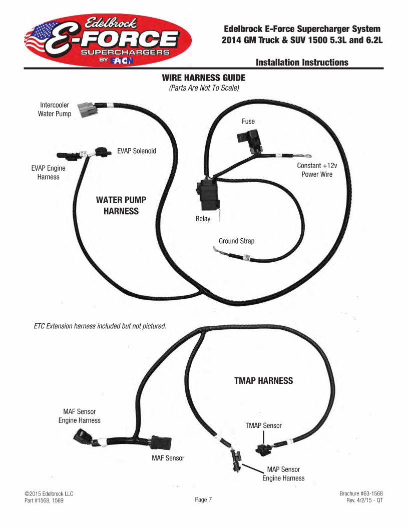
WIRE HARNESS GUIDE(Parts Are Not To Scale)
Constant +12v Power Wire
EVAP Engine Harness
TMAP Sensor
Fuse
Relay
Ground Strap
Intercooler Water Pump
MAF Sensor Engine Harness
MAP Sensor Engine Harness
EVAP Solenoid
MAF Sensor
TMAP HARNESS
WATER PUMP HARNESS
ETC Extension harness included but not pictured.

©2015 Edelbrock LLCPart #1568, 1569
Brochure #63-1568Rev. 4/2/15 - QT
Edelbrock E-Force Supercharger System 2014 GM Truck & SUV 1500 5.3L and 6.2L
Installation Instructions
Page 8
HOSE ROUTING DIAGRAM
Heat Exchanger (LTR)
Water Pump
Intercooler Reservoir Tank
Supercharger

©2015 Edelbrock LLCPart #1568, 1569
Brochure #63-1568Rev. 4/2/15 - QT
Edelbrock E-Force Supercharger System 2014 GM Truck & SUV 1500 5.3L and 6.2L
Installation Instructions
Page 9
TEMPLATE(DO NOT SCALE TEMPLATE WHEN PRINTING)
Splash Guard Template


©2015 Edelbrock LLCPart #1568, 1569
Brochure #63-1568Rev. 4/2/15 - QT
Edelbrock E-Force Supercharger System 2014 GM Truck & SUV 1500 5.3L and 6.2L
Installation Instructions
Page 11
E-MAIL EDELBROCK YOUR STOCK VEHICLE CALIBRATION AND VEHICLE INFORMATION
PLEASE COMPLETE THIS PROCEDURE PRIOR to starting the installation of your E-Force supercharger system. This will allow our calibration team to complete your calibration file while the installation of your supercharger system is being completed. Manufacturers regularly update the factory calibration, as a result, there is the possibility for delays due to not having access to your current calibration file. This can normally be resolved in 1 business day.
FAILURE TO PROVIDE ALL OF THE INFORMATION BELOW WILL DELAY THE COMPLETION OF THE CALIBRATION FILE FOR YOUR VEHICLE. TO LIMIT VEHICLE DOWN TIME, PLEASE SEND US THE REQUESTED INFORMATION BEFORE STARTING THE SUPERCHARGER INSTALL.
Please e-mail the requested information below to [email protected] with the E-mail Subject as “Calibration Update”. We will complete your calibration and e-mail it back to you as soon as possible. MOST calibration updates will be sent back the same business day. In rare cases, it could take up to 1-2 business days to complete. Please contact our Tech Hot Line at (800)416-8628 if you have any questions or if you need assistance with this procedure.
•Begin by downloading the SCT device updater software to your computer; it can be downloaded from: http://www.sctflash.com/software/SCTDeviceUpdater.exe
•Put the vehicle into ACC mode but do not start the engine.
•Connect the supplied PCM cable from the programmer to the OBD-II connector.
•Select PROGRAM VEHICLE, use the arrow keys to highlight UPLOAD STOCK and press SELECT. Follow the prompts on the screen.
• If the upload fails, you will be asked to AUTO DETECT. Press SELECT and follow the prompts on the screen. If the auto detect fails, please contact Edelbrock Tech Support @ 800-416-8628.
•Once the stock calibration has loaded to the handheld programmer, disconnect the programmer from the OBD-II connector and connect it to your PC using the supplied USB cable.
•Open the SCT software and select the button on the lower left hand side that reads GET STOCK FILE FROM DEVICE. Follow the instructions on the screen. NOTE: The stock calibration file will automatically be labeled using your VIN number followed by “.sul “ (XXXXXXXXXXXXX.sul)
•Once the download is complete, you can E-mail your stock vehicle calibration along with the vehicle information below to [email protected] or call 800-416-8628 and our Tech Support staff will assist you with E-mailing the file. NOTE: The subject line of your E-mail should read “Calibration Update”.
•Once we have the stock calibration file, along with the requested information below, we can update the calibration to work with your application. We will E-mail you the custom calibration which may be used until the release version of the calibration is available.
INFORMATION NEEDED:E-Mail Address:Vehicle Year:Vehicle Make:Vehicle Model (Specify if Z06, Z51, etc..):Engine Size:
Transmission:Fuel Octane (91 or 93 ONLY):Supercharger System Part Number:Supercharger Serial Number:Programmer Serial Number:

©2015 Edelbrock LLCPart #1568, 1569
Brochure #63-1568Rev. 4/2/15 - QT
Edelbrock E-Force Supercharger System 2014 GM Truck & SUV 1500 5.3L and 6.2L
Installation Instructions
Page 10
SUPERCHARGER INSTALLATION
WARNING: Battery must be sufficiently charged before starting the PCM flashing procedure.
Only begin the PCM flashing procedure when you have downloaded the updated calibration file to the handheld programmer. Do not flash the PCM until you are ready to install the supercharger. Once the PCM is flashed, DO NOT START the engine until the installation of the E-Force supercharger is complete.
1. Put the car into ACC mode, but don’t start the vehicle.
2. Connect the supplied PCM cable on the handheld programmer to the OBD-II connector located below the steering wheel, and to the left of your knee.
3. Use the directional pad to highlight the Program Vehicle option and press the Select button.
4. Use the directional pad to highlight the Pre-programmed Tune option and press the Select button.
5. Read the disclaimer then press Select to continue.
6. Verify that the ignition is in the ‘Key On’ position and that the engine is not running, then press Select.
7. Use the directional pad to highlight your vehicle and transmission combination then press Select.
8. Use the directional pad to highlight the Begin Program option then press Select.
9. Depending on your specific drivetrain configuration, several separate operations may take place during this step. Completion of each operation will cause the progress bar to reset to zero.
10. DO NOT unplug the programmer until prompted.
11. Turn the vehicle off when prompted to do so by the handheld programmer.
12. Read the parting message from programmer then press Select to continue.
13. Unplug the programmer cable from the OBD-II port. This concludes the PCM flashing procedure. DO NOT start the engine until the supercharger installation is complete.
14. Using a 10mm socket, disconnect the negative battery terminal.
15. Disconnect the driver and passenger PCV hoses from the air inlet tube assembly and from the valve covers.

©2015 Edelbrock LLCPart #1568, 1569
Brochure #63-1568Rev. 4/2/15 - QT
Edelbrock E-Force Supercharger System 2014 GM Truck & SUV 1500 5.3L and 6.2L
Installation Instructions
Page 11
16. Using a flathead screwdriver, loosen the worm clamps on the air inlet tube and remove the assembly from the throttle body and airbox.
17. Unplug the throttle body harness connector from the throttle body assembly.
18. Unplug the MAP harness connector from the MAP sensor. Remove the EVAP hose from the EVAP solenoid and unplug the EVAP harness connector. TIP: EVAP solenoid is located under the MAP sensor.
MAP
19. Detach the PCV hose located on the valley plate. On 5.3L applications the hose connects to the driver side of the intake manifold. On 6.2L applications, it connects to the front of the intake manifold.
5.3L
6.2L
20. Detach the engine harness from the sides of the manifold cover using a panel puller. OPTIONAL: The wire ties securing the harness to the manifold cover can be removed altogether.
21. Using a 10mm socket, remove ten (10) bolts securing the intake manifold to the cylinder heads.

©2015 Edelbrock LLCPart #1568, 1569
Brochure #63-1568Rev. 4/2/15 - QT
Edelbrock E-Force Supercharger System 2014 GM Truck & SUV 1500 5.3L and 6.2L
Installation Instructions
Page 12
22. Using a panel puller, disengage four (4) Christmas tree push pins securing the engine harness to the rear of the manifold cover. With Christmas trees removed, carefully remove the intake manifold.
23. Clean the intake port surfaces with a shop rag. Cover the ports with protective tape to keep out debris.
24. Drain the coolant by removing the petcock located on the passenger side of the radiator.
25. Remove the two heater hoses located on the passenger side firewall. Please towels or rags underneath the hoses to prevent the coolant from getting into the cylinder.
26. Using a 1/2” breaker bar, rotate the tension counterclockwise and remove the stock drive belt.
27. Using a 15mm socket, remove the factory tensioner.
28. Remove three (3) bolts from the water pump using a 13mm socket.
29. Using Blue thread locker and three (3) M8 x 130mm SHCS bolts from Bag #1, secure the FEAD bracket to the water pump using a 6mm Hex key. Torque bolts to 22 ft-lbs.
30. Remove the factory bolt securing the alternator bracket using a 15mm socket.

©2015 Edelbrock LLCPart #1568, 1569
Brochure #63-1568Rev. 4/2/15 - QT
Edelbrock E-Force Supercharger System 2014 GM Truck & SUV 1500 5.3L and 6.2L
Installation Instructions
Page 13
31. Apply Blue thread locker to one end of the M10 Stud from Bag #1. Thread the stud, by hand, into the alternator bracket. Using the supplied M10 nut from Bag #1, continue threading the stud into the bracket until it stops. Remove the M10 nut.
32. Place the large spacer onto the M10 Stud and secure the smooth idler pulley to the stud with one (1) M10 Washer and one (1) Nut from Bag #1. Torque nut to 18 ft-lbs.
33. Insert the small pulley adapter to the backside of the supplied grooved idler pulley.
34. Using one (1) M10 washer and one (1) M10 x 40mm Hex Flange bolt from Bag #1, install the grooved idler pulley to the factory FEAD bracket . Torque bolt to 18 ft-lbs.
35. Using one (1) M8 washers and one (1) M8 x 25mm bolts from Bag #1, install the other smooth idler pulley to the FEAD bracket with a 12mm socket. Torque bolt to 18 ft-lbs.
36. Remove the O-ring gaskets from the factory intake manifold.
37. Clean and inspect the O-ring gaskets and replace torn or damage O-rings as needed. Using a razor blade, or equivalent, remove the tips off all eight (8) factory O-ring gaskets.
38. Install four (4) modified O-ring gaskets onto the passenger side runner. TIP: Passenger side runner will have a TMAP sensor. Driver side will have an actuator barb.
©2015 Edelbrock LLCPart #1568, 1569
Brochure #63-1568Rev. 4/2/15 - QT
Edelbrock E-Force Supercharger System 2014 GM Truck & SUV 1500 5.3L and 6.2L
Installation Instructions
Page 14
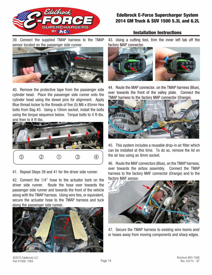
39. Connect the supplied TMAP harness to the TMAP sensor located on the passenger side runner.
40. Remove the protective tape from the passenger side cylinder head. Place the passenger side runner onto the cylinder head using the dowel pins for alignment. Apply Blue thread locker to the threads of five (5) M6 x 85mm Hex bolts from Bag #3. Using a 10mm socket, install the bolts using the torque sequence below. Torque bolts to 4 ft-lbs. and then to 8 ft-lbs.
� � � ��
41. Repeat Steps 39 and 41 for the driver side runner.
42. Connect the 1/4” hose to the actuator barb on the driver side runner. Route the hose over towards the passenger side runner and towards the front of the vehicle along with the TMAP harness. Using wire ties, or equivalent, secure the actuator hose to the TMAP harness and tuck along the passenger side runner.
43. Using a cutting tool, trim the inner left tab off the factory MAP connector.
44. Route the MAP connector, on the TMAP harness (Blue), over towards the front of the valley plate. Connect the TMAP harness to the factory MAP connector (Orange).
45. This system includes a reusable drop-in air filter which can be installed at this time. To do so, remove the lid on the air box using an 8mm socket.
46. Route the MAF connectors (Blue), on the TMAP harness, over towards the airbox assembly. Connect the TMAP harness to the factory MAF connector (Orange) and to the factory MAF sensor.
47. Secure the TMAP harness to existing wire looms and/or hoses away from moving components and sharp edges.

©2015 Edelbrock LLCPart #1568, 1569
Brochure #63-1568Rev. 4/2/15 - QT
Edelbrock E-Force Supercharger System 2014 GM Truck & SUV 1500 5.3L and 6.2L
Installation Instructions
Page 15
48. Using a 10mm socket, remove the factory EVAP solenoid on the intake manifold and install it to the supercharger manifold using the factory bolt.
49. Install the supplied Manifold to Runner gaskets onto the runners. Note that the passenger side gasket will be longer than the driver side gasket. TIP: You can use a dab of gasket maker to help hold the gasket in place while installing the manifold.
NOTE: Due to the length of the runners and the position of the engine, the rear inner bolts need to be taped to the manifold prior to placing the manifold onto the cylinder heads.
50. Using masking tape and six (6) M6 x 90 SHCS bolts from bag #3, tape the bolts to the locations below so the threads are not protruding through the bottom of the manifold.
51. With the help from an assistant, carefully lower the supercharger manifold onto the runners. Make sure to align the manifold to runner gaskets properly before proceeding. TIP: Make sure to keep the gaskets in place as they will have a tenancy to move during the supercharger install.
52. Apply Blue thread locker to the fourteen (14) M6 x 90mm SHCS bolts and two (2) M6 x 20mm SHCS bolts from Bag #3. Place the bolts into their provisions noting that location 13 and 16 will use the M6 x 20mm bolts. Using a 5mm Hex drive, secure the manifold to the runners using the torque sequence below. Torque bolts to 4 ft-lbs. and then to 8 ft-lbs.
1
23
4
5
6
7
8
9
1011
12
13
14
15
16
FRONTM6 x 20mm
53. Using a 15mm socket, reinstall the factory tensioner along with the supplied drive belt. Torque tensioner bolt to 37 ft-lbs.

©2015 Edelbrock LLCPart #1568, 1569
Brochure #63-1568Rev. 4/2/15 - QT
Edelbrock E-Force Supercharger System 2014 GM Truck & SUV 1500 5.3L and 6.2L
Installation Instructions
Page 16
54. Using a breaker bar, rotate the tensioner counterclockwise and install the drive belt using the routing diagram below.
ALT.
IDLER
IDLERIDLER
S / C
TEN.
CRANK
WATER PUMP
CAUTION: Step 55 must be performed properly to prevent any driveability issues that may occur.
55. Using the supplied .015” taper jet, position the stem of the jet into the actuator fitting. Secure the jet to the actuator by connecting the previously installed actuator hose to the actuator. Trim the hose to length if necessary.
Stem
56. Using a 10mm socket, remove a bolt and nut securing the engine harness support right of the new EVAP location. Carefully lift up the harness support and temporarily relocate it to access the EVAP solenoid.
57. With the engine harness temporarily relocated, connect the factory EVAP hose to the EVAP solenoid.
58. Install the straight fitting on the Valley to Nose PCV hose to the quick connect fitting located at the front of the valley plate. Connect the 90° end to the quick connect fitting on the manifold nose.

©2015 Edelbrock LLCPart #1568, 1569
Brochure #63-1568Rev. 4/2/15 - QT
Edelbrock E-Force Supercharger System 2014 GM Truck & SUV 1500 5.3L and 6.2L
Installation Instructions
Page 17
59. Using a 10mm socket, remove the throttle body from the stock manifold and install it onto the supercharger manifold using the factory bolts and the supplied throttle body O-ring gasket. NOTE: Throttle body flange is tapped for both 5.3L and 6.2L throttle bodies. Verify proper alignment before securing the throttle body.
60. Connect the supplied ETC extension harness to the factory throttle body connector. Route the harness under the supercharger nose and connect to the throttle body. Secure the ETC extension harness to existing wire looms and/or hoses away from moving components and sharp edges.
61. Using a panel puller, remove twelve (12) push pins securing the top shroud.
62. Using a 10mm socket, remove four (4) bolts securing the top of the grill assembly. Some vehicles with have a total of five (5) bolts.
NOTE: Steps 63-66 will outline the procedure to remove the front facia on Truck applications. Disregard and skip to Step 68 if installing on SUV applications.
63. Vehicles equipped with fender guards, use a 7mm ratchet and a Torx T15 to remove the front two bolts.
64. Carefully disengage the fender guard by dislodging the front plastic retaining clips. TIP: Fender guard does not have to be fully removed.

©2015 Edelbrock LLCPart #1568, 1569
Brochure #63-1568Rev. 4/2/15 - QT
Edelbrock E-Force Supercharger System 2014 GM Truck & SUV 1500 5.3L and 6.2L
Installation Instructions
Page 18
65. Using a 7mm socket, remove four (4) bolts (two per side) securing the grill assembly. Proceed to Step 71. TIP: Fender lining doesn’t have to be removed, but will simplify this procedure.
66. Remove four (4) additional bolts securing the grill assembly using a 10mm socket. TIP: These need to be removed from the bottom of the vehicle.
NOTE: Steps 67-69 will outline the procedure to remove the front facia on SUV applications. Disregard otherwise.
67. Using a 7mm socket remove six (6) screws, per side, securing the wheel well liner to the facia. The wheel well liner does not have to be completely removed.
68. Using a panel puller, remove two (2) push pins (GREEN ARROW) securing the wheel well liner to the bottom of the facia. Using a 10mm socket, remove four (4) bolts securing the wheel well liner to the bottom of the front fascia and two (2) bolts securing the facia to the chassis.
69. Using a 10mm socket, remove two (2) additional bolts securing the front fascia to the chassis.
70. With the help from an assistant, carefully disengage the front fascia assembly and remove. TIP: Grill will detach with the fascia as an assembly.
©2015 Edelbrock LLCPart #1568, 1569
Brochure #63-1568Rev. 4/2/15 - QT
Edelbrock E-Force Supercharger System 2014 GM Truck & SUV 1500 5.3L and 6.2L
Installation Instructions
Page 19
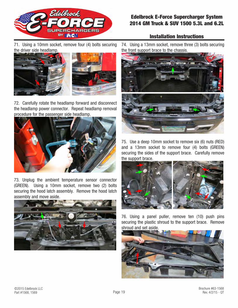
71. Using a 10mm socket, remove four (4) bolts securing the driver side headlamp.
72. Carefully rotate the headlamp forward and disconnect the headlamp power connector. Repeat headlamp removal procedure for the passenger side headlamp.
73. Unplug the ambient temperature sensor connector (GREEN). Using a 10mm socket, remove two (2) bolts securing the hood latch assembly. Remove the hood latch assembly and move aside.
74. Using a 13mm socket, remove three (3) bolts securing the front support brace to the chassis.
75. Use a deep 10mm socket to remove six (6) nuts (RED) and a 13mm socket to remove four (4) bolts (GREEN) securing the sides of the support brace. Carefully remove the support brace.
76. Using a panel puller, remove ten (10) push pins securing the plastic shroud to the support brace. Remove shroud and set aside.

©2015 Edelbrock LLCPart #1568, 1569
Brochure #63-1568Rev. 4/2/15 - QT
Edelbrock E-Force Supercharger System 2014 GM Truck & SUV 1500 5.3L and 6.2L
Installation Instructions
Page 20
NOTE: There are two variants of the front support brace. Variant I has a flat support plate while Variant II has a support plate with raised sides. If you have variant II, proceed to Step 77. Otherwise disregard and proceed to Step 78.
VARIANT II
VARIANT I
77. Using a right angle grinder, or equivalent, trim the sides of the support plate 35mm from where the plate meets the brace. The depth of the relief needs to be approximately 10mm. Deburr all sharp edges with a file and touch up relief with black paint. Proceed to Step 78.
35mm
10mm
78. Apply 3-4” of foam tape to the support bars to prevent LTR and brace contact. Vehicles with Variant II type braces apply the supplied edge trim to the reliefs on the support plate. Trim edge trim as needed.
Foam Tape
Edge Trim
79. Position the Low Temp Radiator (LTR) on the backside of the support brace with the barbs pointing towards the driver side of the vehicle and the offset closer towards the front of the vehicle.
Driver side Barbs
Offset
80. Using the LTR brackets and four (4) M6 x 10mm bolts from Bag #2, loosely secure the LTR brackets to the LTR. TIP: Refer to Page 5 for LTR bracket orientation.

©2015 Edelbrock LLCPart #1568, 1569
Brochure #63-1568Rev. 4/2/15 - QT
Edelbrock E-Force Supercharger System 2014 GM Truck & SUV 1500 5.3L and 6.2L
Installation Instructions
Page 21
81. Using a 10mm socket, remove two (2) lower bolts on the support brace. Using the same bolts, loosely secure the lower LTR brackets to the support brace. Using two (2) M8 x 16mm BHCS bolts and two M8 washers from Bag #2, loosely secure the top LTR brackets to the support brace.
Stock Bolt Stock Bolt
SHCS Bolt SHCS Bolt
82. Place the shroud back onto the support brace and adjust the LTR as needed. With the LTR properly aligned, remove the shroud and securely fasten all LTR bolts.
83. Place the shroud back onto the support brace and pull back the rubber weather guard. Using a marker, mark the relief cutouts for the LTR hoses. Reliefs should be approximately 1.5” wide and 1/2” below the LTR barbs.
84. Trim the shroud using an appropriate cutting tool. Test fit the LTR hoses to verify proper shroud to hose clearance. Reinstall the weather guard and trim the rubber weather guard as needed. Re-secure shroud to support brace using the factory fasteners.
85. Install the LTR to Manifold hose to the top LTR barb and secure with a hose clamp from Bag #2. TIP: Use the hose routing diagram to reference how to clock these hoses.
86. Install the LTR to Water Pump hose to the lower LTR barb and secure with a hose clamp from Bag #2. TIP: Use the hose routing diagram to reference how to clock these hoses.
87. With the LTR secured to the support brace, carefully reposition the support brace by feeding the LTR hoses through the cavity between the radiator and the windshield washer fluid tank.

©2015 Edelbrock LLCPart #1568, 1569
Brochure #63-1568Rev. 4/2/15 - QT
Edelbrock E-Force Supercharger System 2014 GM Truck & SUV 1500 5.3L and 6.2L
Installation Instructions
Page 22
88. Re-secure the support brace to the chassis using the factory hardware.
89. Using a 10mm socket, reinstall the hood latch using the factory hardware. Reconnect the ambient temperature sensor connector (GREEN).
90. Reattach the ambient temperature sensor to the support brace so that the sensor is facing the LTR.
91. Reinstall the front grill assembly using the factory hardware.
92. Using a hose clamp from Bag #2, secure the LTR to Manifold hose to the front barb on the water crossover.
93. Using a 10mm socket and four (4) M6 x 10mm Hex Flange bolts from Bag #2, secure the recovery tank bracket to the recovery tank. Install the Recovery Tank to Water Pump hose to the bottom barb on the recovery tank and secure with a hose clamp from Bag #2.
94. Using a 10mm socket, remove two inner bolts securing the battery tray. Route the Recovery Tank to Water Pump hose down towards the ECU splash shield. Use the factory hardware to secure the recovery tank assembly to the battery tray.
95. Using two hose clamps from Bag #2, secure the Manifold to Recovery Tank hose to the rear barb on the water crossover and to the recovery tank.
©2015 Edelbrock LLCPart #1568, 1569
Brochure #63-1568Rev. 4/2/15 - QT
Edelbrock E-Force Supercharger System 2014 GM Truck & SUV 1500 5.3L and 6.2L
Installation Instructions
Page 23
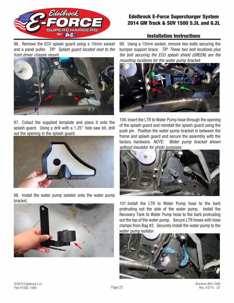
96. Remove the ECU splash guard using a 10mm socket and a panel puller. TIP: Splash guard located next to the front driver chassis mount.
97. Cutout the supplied template and place it onto the splash guard. Using a drill with a 1.25” hole saw bit, drill out the opening in the splash guard.
98. Install the water pump isolator onto the water pump bracket.
99. Using a 15mm socket, remove two bolts securing the bumper support brace. TIP: These two bolt locations plus the bolt securing the ECU splash shield (GREEN) are the mounting locations for the water pump bracket.
100. Insert the LTR to Water Pump hose through the opening of the splash guard and reinstall the splash guard using the push pin. Position the water pump bracket in between the frame and splash guard and secure the assembly with the factory hardware. NOTE: Water pump bracket shown without insulator for photo purposes.
101. Install the LTR to Water Pump hose to the barb protruding out the side of the water pump. Install the Recovery Tank to Water Pump hose to the barb protruding out the top of the water pump. Secure LTR hoses with hose clamps from Bag #2. Securely install the water pump to the water pump isolator.
©2015 Edelbrock LLCPart #1568, 1569
Brochure #63-1568Rev. 4/2/15 - QT
Edelbrock E-Force Supercharger System 2014 GM Truck & SUV 1500 5.3L and 6.2L
Installation Instructions
Page 24
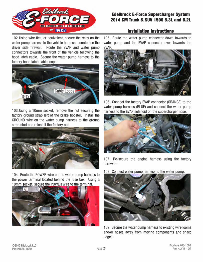
102. Using wire ties, or equivalent, secure the relay on the water pump harness to the vehicle harness mounted on the driver side firewall. Route the EVAP and water pump connectors towards the front of the vehicle following the hood latch cable. Secure the water pump harness to the factory hood latch cable loops.
RelayCable Loops
103. Using a 10mm socket, remove the nut securing the factory ground strap left of the brake booster. Install the GROUND wire on the water pump harness to the ground strap stud and reinstall the factory nut.
104. Route the POWER wire on the water pump harness to the power terminal located behind the fuse box. Using a 10mm socket, secure the POWER wire to the terminal.
105. Route the water pump connector down towards to water pump and the EVAP connector over towards the EVAP.
106. Connect the factory EVAP connector (ORANGE) to the water pump harness (BLUE) and connect the water pump harness to the EVAP solenoid on the supercharger nose.
107. Re-secure the engine harness using the factory hardware.
108. Connect water pump harness to the water pump.
109. Secure the water pump harness to existing wire looms and/or hoses away from moving components and sharp edges.
©2015 Edelbrock LLCPart #1568, 1569
Brochure #63-1568Rev. 4/2/15 - QT
Edelbrock E-Force Supercharger System 2014 GM Truck & SUV 1500 5.3L and 6.2L
Installation Instructions
Page 25
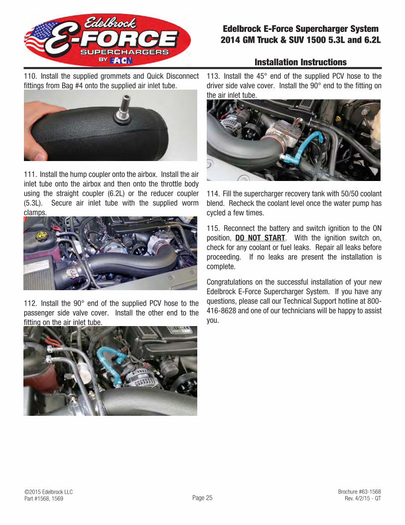
110. Install the supplied grommets and Quick Disconnect fittings from Bag #4 onto the supplied air inlet tube.
111. Install the hump coupler onto the airbox. Install the air inlet tube onto the airbox and then onto the throttle body using the straight coupler (6.2L) or the reducer coupler (5.3L). Secure air inlet tube with the supplied worm clamps.
112. Install the 90° end of the supplied PCV hose to the passenger side valve cover. Install the other end to the fitting on the air inlet tube.
113. Install the 45° end of the supplied PCV hose to the driver side valve cover. Install the 90° end to the fitting on the air inlet tube.
114. Fill the supercharger recovery tank with 50/50 coolant blend. Recheck the coolant level once the water pump has cycled a few times.
115. Reconnect the battery and switch ignition to the ON position, DO NOT START. With the ignition switch on, check for any coolant or fuel leaks. Repair all leaks before proceeding. If no leaks are present the installation is complete.
Congratulations on the successful installation of your new Edelbrock E-Force Supercharger System. If you have any questions, please call our Technical Support hotline at 800-416-8628 and one of our technicians will be happy to assist you.