edf energy r&d uk centre - code-aster.org · pdf filepressure vessel control rods graphite...
TRANSCRIPT

EDF Energy R&D UK CentreAdvantages of Code_Aster for integrity assessments on large scale
structures featuring cracks within a residual stress field
Presented by Jefri Draup
On 16/13/2017 in EDF Saclay, Paris

Contents
R&D UK Centre - Low Carbon GenerationNOT PROTECTIVELY MARKED, R&D UK Centre, Slides R&D UK Centre Guidelines 2
1. Background and motivation
2. Experimental setup
3. Numerical methods
4. Results
5. Conclusions

1. Background and motivation
2. Experimental setup
3. Numerical methods
4. Results
5. Conclusions
R&D UK CentreNOT PROTECTIVELY MARKED, R&D UK Centre, Slides R&D UK Centre Guidelines 3
Background and Motivation
R&D UK CentreNOT PROTECTIVELY MARKED, R&D UK Centre, Slides R&D UK Centre Guidelines 4
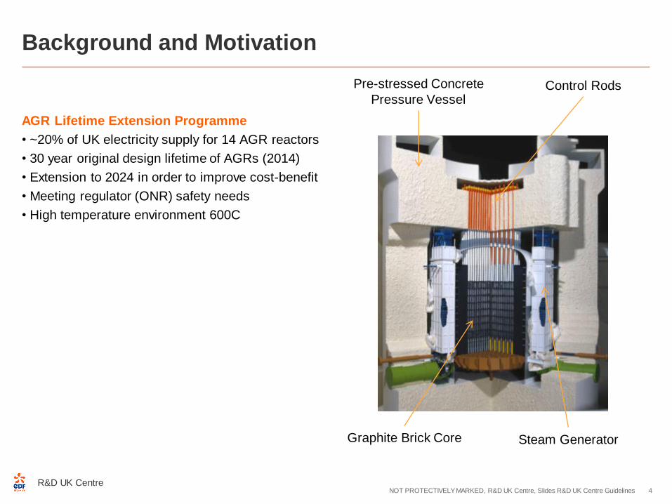
Pre-stressed Concrete
Pressure VesselControl Rods
Graphite Brick Core Steam Generator
AGR Lifetime Extension Programme
• ~20% of UK electricity supply for 14 AGR reactors
• 30 year original design lifetime of AGRs (2014)
• Extension to 2024 in order to improve cost-benefit
• Meeting regulator (ONR) safety needs
• High temperature environment 600C

Background and Motivation
R&D UK CentreNOT PROTECTIVELY MARKED, R&D UK Centre, Slides R&D UK Centre Guidelines 5
AGR Lifetime Extension Programme
• ~20% of UK electricity supply for 14 AGR reactors
• 30 year original design lifetime of AGRs (2014)
• Extension to 2024 in order to improve cost-benefit
• Meeting regulator (ONR) safety needs
• High temperature environment 600C
Operational Issues
• Inspection of Heysham boiler spine revealed the presence
of a structural defect1
• Replacement of boilers not feasible due to design
• The need to understand the conditions within the steam
generator in-service is required
• The potential loss in revenue if boilers and reactors have to
be shut down is significant
~650oC / 40bar
CO2
Boiler Spine
Austenitic 316
stainless steel
Ferritic 9 Cr
Mild Steel1Specification of Heysham 1 reactor 2 boiler spine structural integrity safety case & justification for return
to full power following implementation of the spine cooling modification, NP-SC 7728, EC355061, Office
for Nuclear Regulation Report (ONR-HYA-PAR-15-012), 2015

1. Background and motivation
2. Experimental setup
3. Numerical methods
4. Results
5. Conclusions
R&D UK CentreNOT PROTECTIVELY MARKED, R&D UK Centre, Slides R&D UK Centre Guidelines 6

Experimental Setup
R&D UK CentreNOT PROTECTIVELY MARKED, R&D UK Centre, Slides R&D UK Centre Guidelines 7
STYLE MU2 Specimen:
• 2 lengths of Esshete 1250 austenitic S.S.
• Joined by a girth weld (TIG) and cap dressing
• Introduce a manual repair weld (MMA) and cap dressing
• Residual Stress measurement (iDHD/contour)

Experimental Setup
R&D UK CentreNOT PROTECTIVELY MARKED, R&D UK Centre, Slides R&D UK Centre Guidelines 8
STYLE MU2 specimen:
• Electro Discharge Machining to introduce a
chevron notch
• Four point bending setup with extension arms
welded into place
• Fatigue pre-crack introduce through loading
Chevron notchFatigue Pre-crack

Experimental Setup
R&D UK CentreNOT PROTECTIVELY MARKED, R&D UK Centre, Slides R&D UK Centre Guidelines 9
A large-scale four point bending
test performed by CEA (France) as
part of the EU programme, STYLE
13m
1. Background and motivation
2. Experimental setup
3. Numerical methods
4. Results
5. Conclusions
R&D UK CentreNOT PROTECTIVELY MARKED, R&D UK Centre, Slides R&D UK Centre Guidelines 10
Numerical Methods – Overall Strategy
R&D UK CentreNOT PROTECTIVELY MARKED, R&D UK Centre, Slides R&D UK Centre Guidelines 11
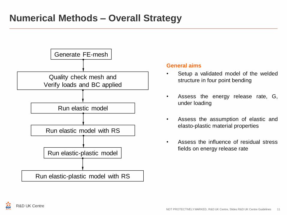
Generate FE-mesh
Run elastic model
Run elastic-plastic model
Run elastic-plastic model with RS
Quality check mesh and
Verify loads and BC applied
Run elastic model with RS
General aims
• Setup a validated model of the welded
structure in four point bending
• Assess the energy release rate, G,
under loading
• Assess the assumption of elastic and
elasto-plastic material properties
• Assess the influence of residual stress
fields on energy release rate

Numerical Methods – Model Details
R&D UK CentreNOT PROTECTIVELY MARKED, R&D UK Centre, Slides R&D UK Centre Guidelines 12
MU2 pipeExtension armExtension arm
11 m
1.0 m
13 m
Inner loading point Supporting point
( Outer loading point)
Supporting point
( Outer loading point)
Geometry
Half symmetry
Loading and Boundary Conditions

Mesh
• 8 node Hexahedron elements used to mesh structure (500,000el)
• Mesh refined towards weld region and crack region (0.15mm at
crack tip after mesh sensitivity study)
• Cracks modelled as sharp crack and notch
Numerical Methods – Model Details
R&D UK CentreNOT PROTECTIVELY MARKED, R&D UK Centre, Slides R&D UK Centre Guidelines 13
Crack Tip Crack Tip
Mesh 1 Mesh 2 Mesh 3
Sharp crack Notch crack
Sharp crack
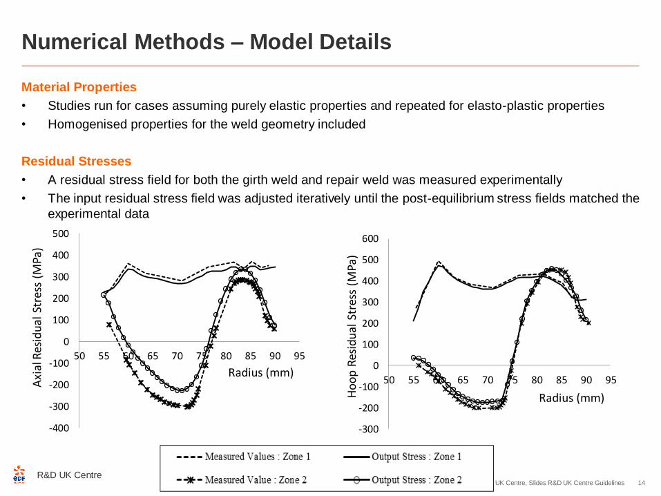
Material Properties
• Studies run for cases assuming purely elastic properties and repeated for elasto-plastic properties
• Homogenised properties for the weld geometry included
Residual Stresses
• A residual stress field for both the girth weld and repair weld was measured experimentally
• The input residual stress field was adjusted iteratively until the post-equilibrium stress fields matched the
experimental data
Numerical Methods – Model Details
R&D UK CentreNOT PROTECTIVELY MARKED, R&D UK Centre, Slides R&D UK Centre Guidelines 14
-400
-300
-200
-100
0
100
200
300
400
500
50 55 60 65 70 75 80 85 90 95
Axi
al R
esid
ual
Str
ess
(MPa
)
Radius (mm)
-300
-200
-100
0
100
200
300
400
500
600
50 55 60 65 70 75 80 85 90 95
Ho
op
Res
idu
al S
tres
s (M
Pa)
Radius (mm)

Mechanical Analysis
• Mechanical analysis STAT_NON_LINE to compute global field variables
Post-Processing
• The energy release rate (G) around the crack was computed using CALC_G
• For elastic conditions the option ‘CALC_G’ was used and the solution compared to R6 guidelines
• For elasto-plastic conditions the option ‘CALC_GTP’ was used
• For each case the analysis was repeated for to include residual stresses
Benchmarking
• The prediction of energy release rate in Code_Aster was compared to J integral calculations in
ABAQUS
Numerical Methods – Model Details
R&D UK CentreNOT PROTECTIVELY MARKED, R&D UK Centre, Slides R&D UK Centre Guidelines 15
1. Background and motivation
2. Experimental setup
3. Numerical methods
4. Results
5. Conclusions
R&D UK CentreNOT PROTECTIVELY MARKED, R&D UK Centre, Slides R&D UK Centre Guidelines 16

R&D UK CentreNOT PROTECTIVELY MARKED, R&D UK Centre, Slides R&D UK Centre Guidelines 17
Results – Parametric Studies
• Mesh resolution study showed that element of 0.15mm at notched crack tip is optimal
• Parametric smoothing study indicates Legendre smoothing Degree 5 is optimal
• This mesh and smoothing function is used on subsequent analysis
0,00
0,05
0,10
0,15
0,20
0,25
50 55 60 65 70 75 80 85 90 95
G (
MJ/
m)
R(mm)
G at U2 = 75 mm (Bending Moment = 230 kN-m)Aster RI=0,001 RS =0,005
R6-Ref
CALC_K_G Smoothing default
CALC_G Smoothing default
CALC_K_G Smoothing LAGRANGE_REGU
CALC_G Smoothing LAGRANGE_REGU
CALC_K_G Smoothing LAGRANGE
CALC_G Smoothing LAGRANGE
CALC_K_G Smoothing LEGENDRE D3
CALC_G Smoothing LEGENDRE D3

Energy release
rate evaluated
here providing
a bending
moment of
~230kNm
R&D UK CentreNOT PROTECTIVELY MARKED, R&D UK Centre, Slides R&D UK Centre Guidelines 18
Results
0
50
100
150
200
250
0,0 0,5 1,0 1,5 2,0 2,5
Reactio
n F
orce (kN
)
CMOD (mm)
The Relationship between Reaction Force & CMOD
Experiment
1/4 model without residual stress (Do and Smith)
1/4 model with residual stress (Do and Smith)
Repeat 1/2 model Aster without residual stress
Repeat 1/2 model Aster with residual stress
1/2 model Aster without residual stress (Sutham)
1/2 model Aster with residual stress (Sutham)
1/2 model Abaqus without residual stress (Sutham)
1/2 model Aster with residual stress (Sutham)

R&D UK CentreNOT PROTECTIVELY MARKED, R&D UK Centre, Slides R&D UK Centre Guidelines 19
Results
• Notched crack used in both Code_Aster and ABAQUS
• Mesh M35 (35 segments at the crack front)
• This corresponds to element sizes of 0.15mm at crack tip
• Energy release rate around the crack calculated at fixed distance ahead of crack tip (G(θ) and J)

R&D UK CentreNOT PROTECTIVELY MARKED, R&D UK Centre, Slides R&D UK Centre Guidelines 20
Results
• For elastic conditions Code_Aster and ABAQUS are in good agreement (<2%)

R&D UK CentreNOT PROTECTIVELY MARKED, R&D UK Centre, Slides R&D UK Centre Guidelines 21
Results
• For elastic conditions Code_Aster and ABAQUS are in good agreement (<2%)
• Residual stress increases G and uncertainty but both software in good agreement (<5%)
• Code aster 2.5h,ABAQUS 3h

R&D UK CentreNOT PROTECTIVELY MARKED, R&D UK Centre, Slides R&D UK Centre Guidelines 22
Results
• For plastic conditions there is significant uncertainty between Code_Aster and ABAQUS (<10%)
R&D UK CentreNOT PROTECTIVELY MARKED, R&D UK Centre, Slides R&D UK Centre Guidelines 23
Results
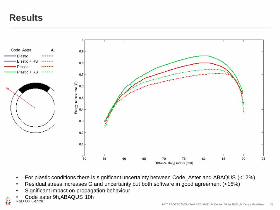
• For plastic conditions there is significant uncertainty between Code_Aster and ABAQUS (<12%)
• Residual stress increases G and uncertainty but both software in good agreement (<15%)
• Significant impact on propagation behaviour
• Code aster 9h,ABAQUS 10h

R&D UK CentreNOT PROTECTIVELY MARKED, R&D UK Centre, Slides R&D UK Centre Guidelines 24
Results – Path Dependence Study
• Notched crack used in both Code_Aster and ABAQUS
• Mesh M35 (35 segments at the crack front)
• This corresponds to element sizes of 0.15mm
• Energy release rate around the crack calculated at fixed distance ahead of crack tip (G(θ) and J)
• Path dependence of G(θ) and J tested with increasing distance from crack tip
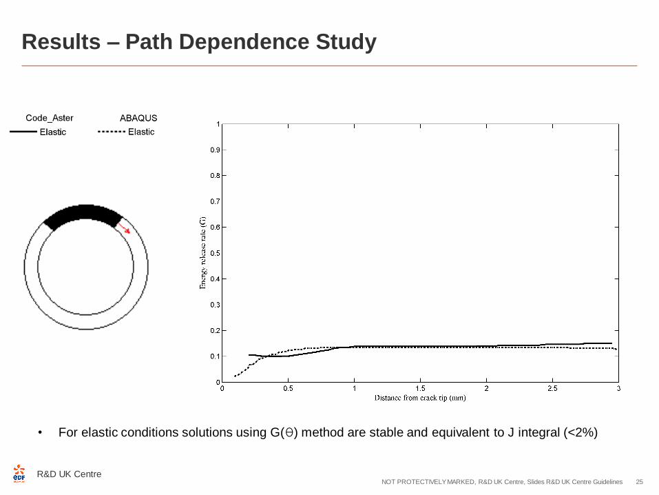
• For elastic conditions solutions using G(θ) method are stable and equivalent to J integral (<2%)
R&D UK CentreNOT PROTECTIVELY MARKED, R&D UK Centre, Slides R&D UK Centre Guidelines 25
Results – Path Dependence Study
R&D UK CentreNOT PROTECTIVELY MARKED, R&D UK Centre, Slides R&D UK Centre Guidelines 26
Results – Path Dependence Study
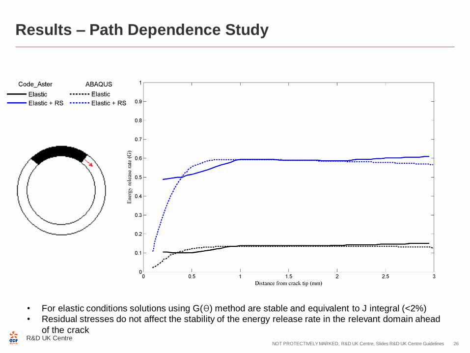
• For elastic conditions solutions using G(θ) method are stable and equivalent to J integral (<2%)
• Residual stresses do not affect the stability of the energy release rate in the relevant domain ahead
of the crack

R&D UK CentreNOT PROTECTIVELY MARKED, R&D UK Centre, Slides R&D UK Centre Guidelines 27
Results – Path Dependence Study
• For plastic conditions solutions using G(θ) method are unstable and differ to J integral (<40%)
R&D UK CentreNOT PROTECTIVELY MARKED, R&D UK Centre, Slides R&D UK Centre Guidelines 28
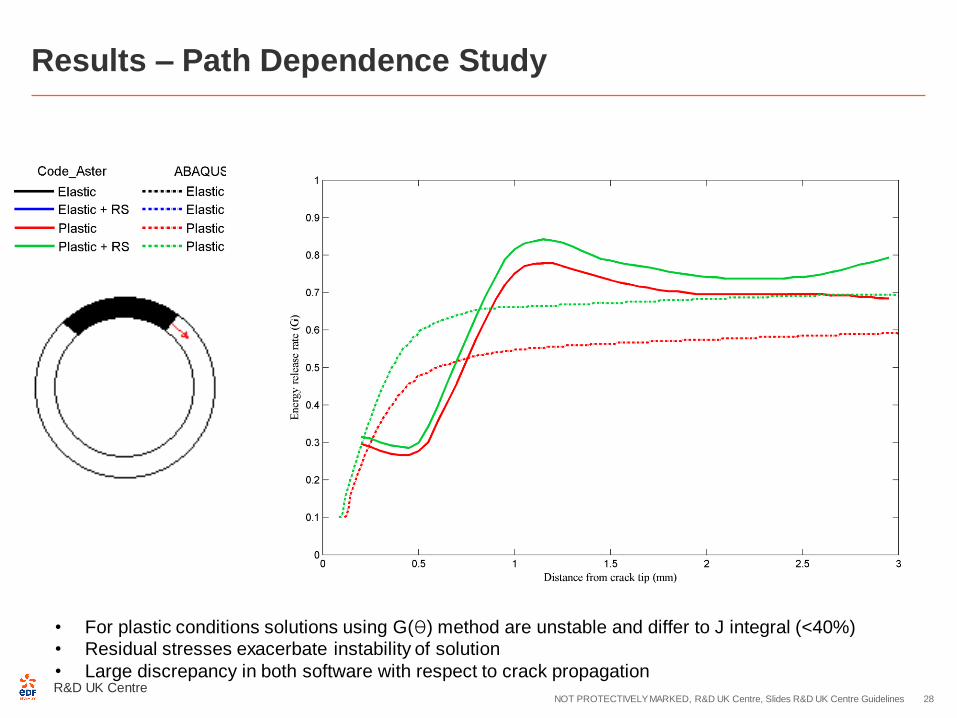
Results – Path Dependence Study
• For plastic conditions solutions using G(θ) method are unstable and differ to J integral (<40%)
• Residual stresses exacerbate instability of solution
• Large discrepancy in both software with respect to crack propagation

R&D UK CentreNOT PROTECTIVELY MARKED, R&D UK Centre, Slides R&D UK Centre Guidelines 29
Results – Theoretical Explanation
THEORETICAL EXPLANATION
• Limitation of G results from the assumed existence of a strain energy density, as a potential from which
stresses can be uniquely derived.
R&D UK CentreNOT PROTECTIVELY MARKED, R&D UK Centre, Slides R&D UK Centre Guidelines 30
Results – Theoretical Explanation
THEORETICAL EXPLANATION
• Limitation of G results from the assumed existence of a strain energy density, as a potential from which
stresses can be uniquely derived.
• The assumption actually does not describe irreversible plastic deformation but hyper-elastic or non-
linear elastic behaviour.
R&D UK CentreNOT PROTECTIVELY MARKED, R&D UK Centre, Slides R&D UK Centre Guidelines 31
Results – Theoretical Explanation
THEORETICAL EXPLANATION
• Limitation of G results from the assumed existence of a strain energy density, as a potential from which
stresses can be uniquely derived.
• The assumption actually does not describe irreversible plastic deformation but hyper-elastic or non-
linear elastic behaviour.
• It excludes any local unloading processes but also any local re-arrangement of local stress

R&D UK CentreNOT PROTECTIVELY MARKED, R&D UK Centre, Slides R&D UK Centre Guidelines 32
Results – Theoretical Explanation
THEORETICAL EXPLANATION
• Limitation of G results from the assumed existence of a strain energy density, as a potential from which
stresses can be uniquely derived.
• The assumption actually does not describe irreversible plastic deformation but hyper-elastic or non-
linear elastic behaviour.
• It excludes any local unloading processes but also any local re-arrangement of local stress
• All loading paths in the stress space are supposed to remain radial so that the ratios of principal
stresses do not change with time.
R&D UK CentreNOT PROTECTIVELY MARKED, R&D UK Centre, Slides R&D UK Centre Guidelines 33
Results – Theoretical Explanation
THEORETICAL EXPLANATION
• Limitation of G results from the assumed existence of a strain energy density, as a potential from which
stresses can be uniquely derived.
• The assumption actually does not describe irreversible plastic deformation but hyper-elastic or non-
linear elastic behaviour.
• It excludes any local unloading processes but also any local re-arrangement of local stress
• All loading paths in the stress space are supposed to remain radial so that the ratios of principal
stresses do not change with time.
• The condition of monotonous global loading of a structure is of course not sufficient to guarantee radial
stress paths in non-homogeneous stress fields.

R&D UK CentreNOT PROTECTIVELY MARKED, R&D UK Centre, Slides R&D UK Centre Guidelines 34
Results – Theoretical Explanation
THEORETICAL EXPLANATION
• Limitation of G results from the assumed existence of a strain energy density, as a potential from which
stresses can be uniquely derived.
• The assumption actually does not describe irreversible plastic deformation but hyper-elastic or non-
linear elastic behaviour.
• It excludes any local unloading processes but also any local re-arrangement of local stress
• All loading paths in the stress space are supposed to remain radial so that the ratios of principal
stresses do not change with time.
• The condition of monotonous global loading of a structure is of course not sufficient to guarantee radial
stress paths in non-homogeneous stress fields.
• Current solid mechanics methodologies require further research to better account for plasticity effects
under deformation

R&D UK CentreNOT PROTECTIVELY MARKED, R&D UK Centre, Slides R&D UK Centre Guidelines 35
Results – Potential Solutions
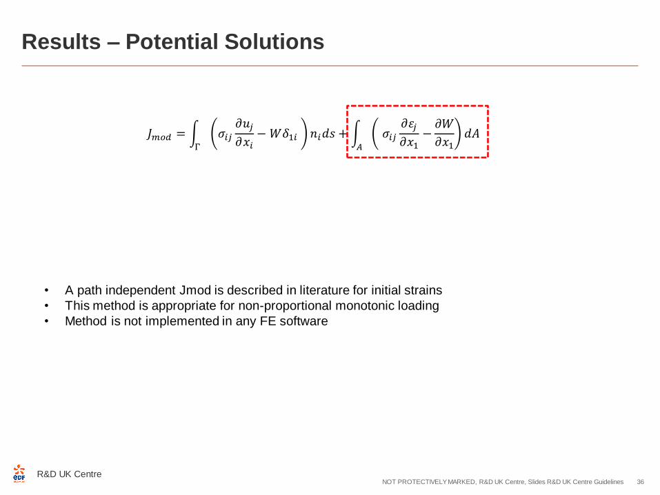
• A path independent Jmod is described in literature for initial strains
• This method is appropriate for non-proportional monotonic loading
• Method is not implemented in any FE software
𝐽𝑚𝑜𝑑 = Γ
𝜎𝑖𝑗𝜕𝑢𝑗𝜕𝑥𝑖
−𝑊𝛿1𝑖 𝑛𝑖𝑑𝑠 + 𝐴
𝜎𝑖𝑗𝜕휀𝑗𝜕𝑥1
−𝜕𝑊
𝜕𝑥1𝑑𝐴
R&D UK CentreNOT PROTECTIVELY MARKED, R&D UK Centre, Slides R&D UK Centre Guidelines 36
Results – Potential Solutions
• A path independent Jmod is described in literature for initial strains
• This method is appropriate for non-proportional monotonic loading
• Method is not implemented in any FE software
𝐽𝑚𝑜𝑑 = Γ
𝜎𝑖𝑗𝜕𝑢𝑗𝜕𝑥𝑖
−𝑊𝛿1𝑖 𝑛𝑖𝑑𝑠 + 𝐴
𝜎𝑖𝑗𝜕휀𝑗𝜕𝑥1
−𝜕𝑊
𝜕𝑥1𝑑𝐴
R&D UK CentreNOT PROTECTIVELY MARKED, R&D UK Centre, Slides R&D UK Centre Guidelines 37
Results – Potential Solutions
𝐽𝑚𝑜𝑑 = Γ
𝜎𝑖𝑗𝜕𝑢𝑗𝜕𝑥𝑖
−𝑊𝛿1𝑖 𝑛𝑖𝑑𝑠 + 𝐴
𝜎𝑖𝑗𝜕휀𝑗𝜕𝑥1
−𝜕𝑊
𝜕𝑥1𝑑𝐴
𝐺𝑚𝑜𝑑(𝜃) = Ω
𝜎𝑖𝑗𝜕𝑢𝑗𝜕𝑥𝑖
𝜕𝜃
𝜕𝑥𝑖− 𝜔𝑑𝑖𝑣𝜃 𝑑Ω +
Ω
𝜎𝑖𝑗𝜕휀𝑗𝜕𝑥1
𝜃 −𝜕𝜔
𝜕𝑥1𝜃 𝑑Ω
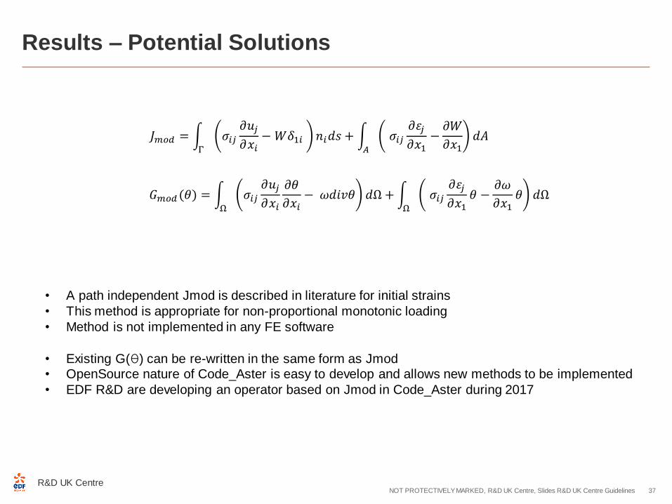
• A path independent Jmod is described in literature for initial strains
• This method is appropriate for non-proportional monotonic loading
• Method is not implemented in any FE software
• Existing G(θ) can be re-written in the same form as Jmod• OpenSource nature of Code_Aster is easy to develop and allows new methods to be implemented
• EDF R&D are developing an operator based on Jmod in Code_Aster during 2017
1. Background and motivation
2. Experimental setup
3. Numerical methods
4. Results
5. Conclusions
R&D UK CentreNOT PROTECTIVELY MARKED, R&D UK Centre, Slides R&D UK Centre Guidelines 38

R&D UK CentreNOT PROTECTIVELY MARKED, R&D UK Centre, Slides R&D UK Centre Guidelines 39
Conclusions
To better understand the Heysham (AGR) incident the STYLE project was
revisited
R&D UK CentreNOT PROTECTIVELY MARKED, R&D UK Centre, Slides R&D UK Centre Guidelines 40
Conclusions
To better understand the Heysham (AGR) incident the STYLE project was
revisited
Systematic models of the experiment were built in Code_Aster to assess
energy release rate of cracks in a residual stress field

R&D UK CentreNOT PROTECTIVELY MARKED, R&D UK Centre, Slides R&D UK Centre Guidelines 41
Conclusions
To better understand the Heysham (AGR) incident the STYLE project was
revisited
Systematic models of the experiment were built in Code_Aster to assess
energy release rate of cracks in a residual stress field
Code_Aster performs comparably to commercial FE software in the realm of
elasticity

R&D UK CentreNOT PROTECTIVELY MARKED, R&D UK Centre, Slides R&D UK Centre Guidelines 42
Conclusions
To better understand the Heysham (AGR) incident the STYLE project was
revisited
Systematic models of the experiment were built in Code_Aster to assess
energy release rate of cracks in a residual stress field
Code_Aster performs comparably to commercial FE software in the realm of
elasticity
Some discrepancies found in G computation in the realm of plasticity
R&D UK CentreNOT PROTECTIVELY MARKED, R&D UK Centre, Slides R&D UK Centre Guidelines 43
Conclusions
To better understand the Heysham (AGR) incident the STYLE project was
revisited
Systematic models of the experiment were built in Code_Aster to assess
energy release rate of cracks in a residual stress field
Code_Aster performs comparably to commercial FE software in the realm of
elasticity
Some discrepancies found in G computation in the realm of plasticity
G(θ) method can be extended to account for initial strains following the method of Lei in Jmod
R&D UK CentreNOT PROTECTIVELY MARKED, R&D UK Centre, Slides R&D UK Centre Guidelines 44
Conclusions
To better understand the Heysham (AGR) incident the STYLE project was
revisited
Systematic models of the experiment were built in Code_Aster to assess
energy release rate of cracks in a residual stress field
Code_Aster performs comparably to commercial FE software in the realm of
elasticity
Some discrepancies found in G computation in the realm of plasticity
G(θ) method can be extended to account for initial strains following the method of Lei in Jmod
This project has led to the development of Jmod based operator in Code_Aster
by EDF SA in 2017

R&D UK CentreNOT PROTECTIVELY MARKED, R&D UK Centre, Slides R&D UK Centre Guidelines 45
END!
Thanks for your time