edge and fog computing platform for data fusion of complex
TRANSCRIPT
sensors
Article
Edge and Fog Computing Platform for Data Fusion ofComplex Heterogeneous Sensors
Gabriel Mujica 1,*,† , Roberto Rodriguez-Zurrunero 2,† , Mark Richard Wilby 3,†,Jorge Portilla 1,† , Ana Belén Rodríguez González 3,†, Alvaro Araujo 2,† ,Teresa Riesgo 1,† and Juan José Vinagre Díaz 3,†
1 Centro de Electrónica Industrial, Universidad Politécnica de Madrid, José Gutiérrez Abascal 2,28006 Madrid, Spain; [email protected] (J.P.); [email protected] (T.R.)
2 B105 Electronic Systems Lab, ETSI Telecomunicación, Universidad Politécnica de Madrid,Avenida Complutense 30, 28040 Madrid, Spain; [email protected] (R.R.-Z.);[email protected] (A.A.)
3 Group Biometry, Biosignals, Security, and Smart Mobility, Universidad Politécnica de Madrid,Avenida Complutense 30, 28040 Madrid, Spain; [email protected] (M.R.W.);[email protected] (A.B.R.G.); [email protected] (J.J.V.D.)
* Correspondence: [email protected]; Tel.: +34-910-676-944† These authors contributed equally to this work.
Received: 7 September 2018; Accepted: 23 October 2018; Published: 25 October 2018�����������������
Abstract: The explosion of the Internet of Things has dramatically increased the data load on networksthat cannot indefinitely increment their capacity to support these new services. Edge computing is aviable approach to fuse and process data on sensor platforms so that information can be created locally.However, the integration of complex heterogeneous sensors producing a great amount of diversedata opens new challenges to be faced. Rather than generating usable data straight away, complexsensors demand prior calculations to supply meaningful information. In addition, the integration ofcomplex sensors in real applications requires a coordinated development from hardware and softwareteams that need a common framework to reduce development times. In this work, we present anedge and fog computing platform capable of providing seamless integration of complex sensors,with the implementation of an efficient data fusion strategy. It uses a symbiotic hardware/softwaredesign approach based on a novel messaging system running on a modular hardware platform. Wehave applied this platform to integrate Bluetooth vehicle identifiers and radar counters in a specificmobility use case, which exhibits an effective end-to-end integration using the proposed solution.
Keywords: edge computing; fog computing; data fusion; multi-sensor systems; complex sensors
1. Introduction
Wireless Sensor Networks (WSNs) is not a new idea, they have been around for more than40 years [1]. Nevertheless, their architecture on implementation is still in progress. Today, WSNshave evolved to incorporate bigger heterogeneous networked systems, ranging from the cloud to theextreme edge. The proliferation of sensors and related devices has been dramatic, embodied in thenow ubiquitous Internet of Things (IoT). This has led to the boundary between the physical world andthe digital being constantly eroded by the IoT, which complicates the nature of what information isbeing generated and where it is needed. However, it is only the early stages of a revolution in access toreal-world information. We are currently dealing with not only the incremental evolution of traditionalsensors in terms of accuracy, latency (communications), etc., but also a fundamental change in thenature of the capabilities of sensors, as well as the growing realization that the significance of the
Sensors 2018, 18, 3630; doi:10.3390/s18113630 www.mdpi.com/journal/sensors
Sensors 2018, 18, 3630 2 of 26
information generated by these sensors depends on the physical observations that may be monitoredby other sensors, i.e., information fusion.
These changes can be interpreted in terms of the different IoT levels, in what has been calledthe continuum cloud-to-things [2]. The bottom layer is located at the edge (where data is created.)Connecting these edges is the computation plan that provides significance to the data collected.Centralised computation leads to massive data uploading to the cloud and latency issues, whichcan be alleviated by bringing decision capabilities to the things [3]. The ability to compute allowsthe dynamic development of edge devices where operations can be evolved bringing functionalchanges to the information that can be retrieved [4]. Specifically, localised processing supportsthe transformation of the collected data into forms more appropriate to the actual monitoring task.Processing raw data typically provides a compression function as well as making the collected dataeasier to interpret and treat. Additional advantages include reduction in data center cost, decrease ofnetwork traffic, scalability increase and simpler IoT devices. However, bringing more computing closeto the physical entities introduces new challenges in terms of allocation of resources and real timeneeds. These challenges are related to the computation offloading among distributed edge devices toavoid hot spots and bottlenecks, distribution of tasks between cloud and edge, communication issuesderived from the mobility and security have to be re-evaluated, to name just a few.
In practical terms this revolution has been precipitated by the introduction of cheap single-boardcomputers (SBC), which has altered the nature and complexity of sensors and the ability to deploy them.We are no longer restricted to simple devices capable of collecting a direct measure of certain variablesfrom the environment, e.g., thermometers or light sensors. We are now open to the relatively easydevelopment of other systems that need some kind of processing to extract a first level of informationfrom the raw data they retrieve. It should be noted that the type of processing can change the nature ofthe provided information received from a physical sensor. Specifically a data stream coming from acamera can be transformed into an arbitrary number of functions (text reading, object tracking, etc.),so a single real sensor can in fact look like, or contribute to, a multitude of different apparent sensors.We use the generic term complex sensors to refer to devices in this class of sensors.
In addition, the ease of fabrication of new types of “Things”, noted as an advantage, is alsoproblematic. The reduction in complexity gained by having local computation has been exacerbatedby the introduction of cheap standard components which can be bolted together to produce novelsystems making the development of a new type of sensor considerably easier. This means today, theintroduction of a new type of sensor is simply one element of a project, rather than being the projectitself. It is not fashionable, but this ability to add new physical capabilities via the introduction of newcustomised hardware and how they can be made to interact with and extend existing systems is a dayto day practical issue. This issue has resulted in the need for a methodology to facilitate the integrationof hardware and software development.
1.1. Motivation
The work we present in this paper grew out of several collaborative projects between the threeresearch groups that form the team. In these projects we developed and deployed a range of complexsensors, where we repetitively faced a common set of integration issues. Invariably this required rapidre-prototyping of hardware systems and going beyond integration of heterogeneous devices requiringa simple and reliable form of communication between software and hardware teams.
Furthermore, in most cases, complex sensors generated huge amounts of raw data that had to beprocessed locally in order to avoid dramatic decreases in the overall performance of the system.
No generic platforms were found that could provide us with a common framework that couldfacilitate the integration and development of sensors and applications across not just softwareboundaries, but also hardware interfaces. Consequently, we needed to produce a hardware andsoftware integration that can extract information at the edge to let developers scale both devicesand applications.
Sensors 2018, 18, 3630 3 of 26
1.2. Contributions
In order to fulfil the previously stated need, we built a complete information framework basedon a novel messaging system shared by both the software application modules and a hardwareintegration platform, namely the Cookie [5]. This resulting common development framework is themain contribution of this paper, achieving a set of improvements:
1. It eases the integration of complex sensors into new or existing networks and applications.2. It extends the concept of the sensor itself, evolving towards a source of data so that anything
generating data (simple and complex sensors, databases, open-data platforms, processingmodules...) could be seamlessly treated and fused in order to develop growing applications.
3. It simplifies the interaction between hardware and software developers. It provides a foundationfor the coordination of teams jointly working on new sensors and/or applications. Although weare not presenting quantitative comparisons, we believe this leads to both a time and costreduction in development.
4. Finally, in order to illustrate these benefits, we have constructed an integrated traffic monitoringsensor that provides both vehicle counting and identification. Fusing the complementary datathis sensor produces, we can obtain extended traffic information, like weighted travel times, thatnone of the original sensors could provide on their own.
2. Related Work
2.1. Edge Computing
Debates regarding which is the best place to situate computing and storage resources have beengoing on since the first computers were networked. On the other side, the answer to such questionswill always be the same: it depends on what you are trying to do. Cloud computing [6] contributesmost in its attempt to provide resources in a transparent and usable form, where the applicationcan adapt the resource to its requirement, rather than the other way around. As a complementaryperspective, edge computing [7] focuses on the periphery of the network.
WSNs can use any of these basic approaches. However, the networked nature of the IoT problem,the increased use of SBCs, improvements in data processing technologies, and the reduction in priceof sensor devices all lead quite obviously to computational resources close to the sensors and henceto edge computing, and more specifically fog computing design methodologies. Fog computing wasdefined as a way to bring computing and storage resources closer to the data generation. This is not inessence very different from the definition of the edge [8]. Even some researchers do not distinguishbetween fog and edge. Their main difference is on the dimension of the hardware elements and theprocessing and storage capabilities resident in the fog and the edge. One aspect that is a key distinctionamong them is that fog does need the cloud to exist. The type of devices that are traditionally connectedwith the fog are network routers, switches and embedded servers, although the heterogeneity and theeffect of SBCs is present in this layer as well.
In fact, edge computing has been shown to be essential to the evolution of IoT [9], but where itis generally seen as a software strategy, we regard it as a solution to a hybrid world of innovationincluding ongoing hardware developments. As it has been mentioned previously, edge computingcan help to solve some inherent problems of the IoT associated with the massive generation of data.The devices located in this level of the IoT may be very different to each other, and usually this bringsother distinction in two layers: the edge and the extreme edge. The main difference among both layersresides in the nature of the devices that are measuring and processing data from the physical world,form the point of view of power consumption, processing capabilities, and communication systems.
The edge now contains gateways acting as bridges onto specific sensor systems as well ashardware embedded devices SBCs all the way through to WSNs, e.g., TelosB motes or similar onesare found [10]. Many of these devices are powered from a mains supply because they have to operate
Sensors 2018, 18, 3630 4 of 26
for months to years and when there is significant computation, there is sizeable power consumption.In many use cases where mobility is not a factor, power availability is not as uncommon as peoplefirst expect. All of these devices need batteries when power is not available as although consumptioncan be made low (in the order of milliwatts), it is still significant. Lifetimes of months are difficult toobtain, when the processing is more intensive than just monitoring and reporting intermittently.
The extreme edge heralds a new generation of highly resource-limited devices with virtuallyno memory, processing capabilities, and local energy store. To operate such systems we requireenergy harvesting techniques, to get what has been called zero or almost zero-power sensors. Somegood examples of devices in this layer are [11,12]. Such devices are crucial for a future realisticimplementation of the IoT paradigm and will only be able to operate by interworking with edge devicesdescribed previously. The development model defined here is ideal for supporting such systems.
2.2. Hardware Integration Platforms
The explosion of the IoT has brought an important evolution of hardware and softwaretechnologies on the edge to cope with the limitations and the intrinsic characteristics of real in-fieldsensor deployments (and even setting novel requirements according to the evolved nature of thepresent and future networks). This fact also implies challenges regarding how to properly handlethe diversity and complexity of the sensing technologies to be deployed. In this way, an end-to-endplatform takes advantage of a modular architecture to allow fast integration of sensing, processing,and communication capabilities on the edge, based on a common hardware definition to fully supportthe concept of heterogeneous complex sensors.
The Cookies platform [13] was conceived to guarantee a flexible and seamless integration ofdifferent technologies thanks to the modular nature of the architecture, where individual elementsthat compose the sensor node can be replaced or updated without altering the overall structure ofthe platform. Consequently, it fosters the re-usability of hardware components and it is also designedfor the re-use of its software components. The modularity of the Cookies empowers the conceptof integrating heterogeneous complex sensors on the edge by providing a well-defined hardwareframework and basic rules for the implementation of different and multiple sensing capabilities.
Although such a modularity allows including a different number of layers into the hardwarestack, the basic composition of a Cookie node features 4 main layers that correspond to the baselinefunctionalities of a WSN and IoT edge device. First, the communication layer where the low-powernetworking technology is integrated so as to supply the sensor node with wireless connectivity withthe surrounding edge elements and the fog layer (direct or indirect according to the type of topologyto be adopted). The intrinsic nature of the Cookie platform as a fast-prototyping architecture hasled to integrate different wireless communication standards, including the well-established WSNIEEE 802.15.4 and ZigBee stacks, and also more resent specifications such as the Internet Protocolversion six (IPv6) over Low-power Wireless Personal Area Networks (6LowPAN) and the Long RangeLow Power, Wide Area (LoRa) network protocols.
Second, the sensor layer, in which the physical interaction with the target environment isperformed by integrating the sensing technologies and, in particular, the complex sensors thatoperate within the proposed heterogeneous edge nodes. The Cookie architecture has allowed theimplementation of different sensing capabilities during the development and deployment of realWSNs in real application scenarios, encompassing carbon dioxide, air alkalinity and pH sensors forenvironmental and industrial monitoring.
Third, the processing layer, which represents the core of the edge node and it is in charge ofperforming the management of the overall sensor device, ranging from basic sensing retrieval and rawdata transmission to the base-station, up to further local processing and data fusion of complex sensorsin accordance with the IoT application requirements. Indeed, such requirements will also define thespecification of the type of processing elements to be integrated. In general terms, the main Cookieprocessing layer is composed of 8051-based microcontrollers (as described subsequently in the use
Sensors 2018, 18, 3630 5 of 26
case section) particularly those designed for low-power and ultra-low-power purposes. In addition,other processing architectures have been used, comprising the very well-known MSP430FG439microcontroller from Texas Instruments (Dallas, TX, USA) [14] and ARM-based processors suchas the ATSAMD21 from Microchip (Chandler, AZ, USA) [15] that features a Cortex-M0+-based 256 KBflash low-power microcontroller.
Finally the power supply layer, which provides the different voltage levels to the rest of thehardware elements in the Cookie node. Depending on the input power source (typically a battery),this layer is designed to satisfy the power requirements of the processing, communication and sensingtechnologies in such a way that the stability and long-term operability of the overall node is assured.This means that additional power adaptation apart from typical linear regulators (for instance, theinclusion of a power management unit) can be performed in this layer. The general architecture of theCookie nodes establishes standard voltage levels that shall be taken into account when designing anew modular layer, although this does not limit the specification of additional reference values or eventhe implementation of further dedicated power transformations into the design of a custom layer.
As it can be seen, the Cookie node serves as a technology gathering platform to speed up theresearch and implementation of particular functionalities by just replacing or combining severalpieces of hardware layers into the sensor nodes. This means that new prototypes can be integratedin combination with already well-established layers, so as to facilitate the experimentation of newstandards and methods under the umbrella of a supportive and stable platform.
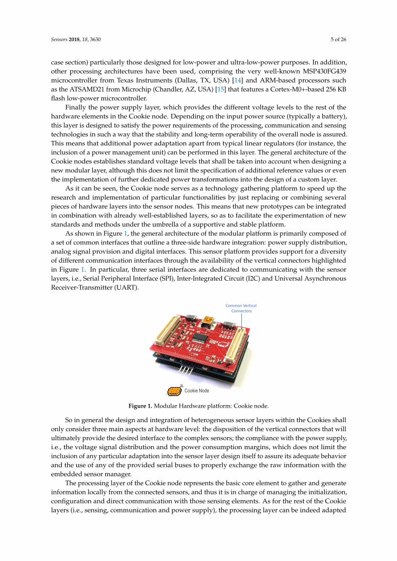
As shown in Figure 1, the general architecture of the modular platform is primarily composed ofa set of common interfaces that outline a three-side hardware integration: power supply distribution,analog signal provision and digital interfaces. This sensor platform provides support for a diversityof different communication interfaces through the availability of the vertical connectors highlightedin Figure 1. In particular, three serial interfaces are dedicated to communicating with the sensorlayers, i.e., Serial Peripheral Interface (SPI), Inter-Integrated Circuit (I2C) and Universal AsynchronousReceiver-Transmitter (UART).
Cookie Node
Common Vertical Connectors
Figure 1. Modular Hardware platform: Cookie node.
So in general the design and integration of heterogeneous sensor layers within the Cookies shallonly consider three main aspects at hardware level: the disposition of the vertical connectors that willultimately provide the desired interface to the complex sensors; the compliance with the power supply,i.e., the voltage signal distribution and the power consumption margins, which does not limit theinclusion of any particular adaptation into the sensor layer design itself to assure its adequate behaviorand the use of any of the provided serial buses to properly exchange the raw information with theembedded sensor manager.
The processing layer of the Cookie node represents the basic core element to gather and generateinformation locally from the connected sensors, and thus it is in charge of managing the initialization,configuration and direct communication with those sensing elements. As for the rest of the Cookielayers (i.e., sensing, communication and power supply), the processing layer can be indeed adapted
Sensors 2018, 18, 3630 6 of 26
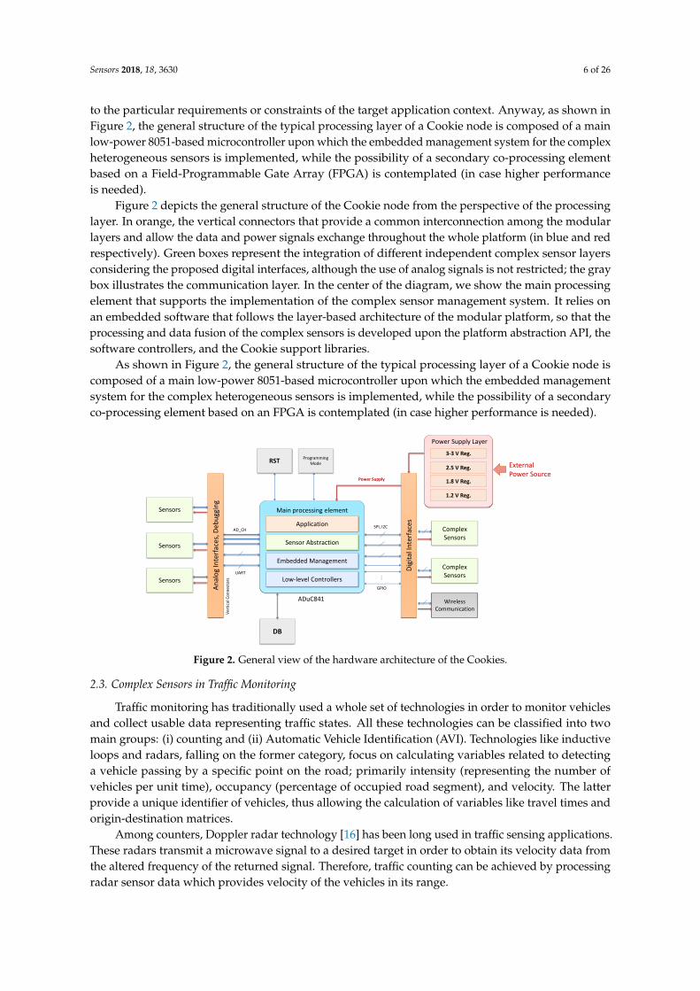
to the particular requirements or constraints of the target application context. Anyway, as shown inFigure 2, the general structure of the typical processing layer of a Cookie node is composed of a mainlow-power 8051-based microcontroller upon which the embedded management system for the complexheterogeneous sensors is implemented, while the possibility of a secondary co-processing elementbased on a Field-Programmable Gate Array (FPGA) is contemplated (in case higher performanceis needed).
Figure 2 depicts the general structure of the Cookie node from the perspective of the processinglayer. In orange, the vertical connectors that provide a common interconnection among the modularlayers and allow the data and power signals exchange throughout the whole platform (in blue and redrespectively). Green boxes represent the integration of different independent complex sensor layersconsidering the proposed digital interfaces, although the use of analog signals is not restricted; the graybox illustrates the communication layer. In the center of the diagram, we show the main processingelement that supports the implementation of the complex sensor management system. It relies onan embedded software that follows the layer-based architecture of the modular platform, so that theprocessing and data fusion of the complex sensors is developed upon the platform abstraction API, thesoftware controllers, and the Cookie support libraries.
As shown in Figure 2, the general structure of the typical processing layer of a Cookie node iscomposed of a main low-power 8051-based microcontroller upon which the embedded managementsystem for the complex heterogeneous sensors is implemented, while the possibility of a secondaryco-processing element based on an FPGA is contemplated (in case higher performance is needed).
Low-level Controllers
Embedded Management
Sensor Abstraction
Application
Main processing element
ADuC841
Dig
ital
Inte
rfac
es
An
alo
g In
terf
aces
, Deb
ugg
ing
DB
ComplexSensors
ComplexSensors
WirelessCommunication
Sensors
Sensors
Sensors
RSTProgramming
Mode
AD_CH
UART
GPIO
…
SPI, I2C
Power Supply
Ver
tica
l Co
nn
ecto
rs
Power Supply Layer
2.5 V Reg.
3-3 V Reg.
1.8 V Reg.
1.2 V Reg.
External Power Source
Figure 2. General view of the hardware architecture of the Cookies.
2.3. Complex Sensors in Traffic Monitoring
Traffic monitoring has traditionally used a whole set of technologies in order to monitor vehiclesand collect usable data representing traffic states. All these technologies can be classified into twomain groups: (i) counting and (ii) Automatic Vehicle Identification (AVI). Technologies like inductiveloops and radars, falling on the former category, focus on calculating variables related to detectinga vehicle passing by a specific point on the road; primarily intensity (representing the number ofvehicles per unit time), occupancy (percentage of occupied road segment), and velocity. The latterprovide a unique identifier of vehicles, thus allowing the calculation of variables like travel times andorigin-destination matrices.
Among counters, Doppler radar technology [16] has been long used in traffic sensing applications.These radars transmit a microwave signal to a desired target in order to obtain its velocity data fromthe altered frequency of the returned signal. Therefore, traffic counting can be achieved by processingradar sensor data which provides velocity of the vehicles in its range.
Sensors 2018, 18, 3630 7 of 26
A radar transceiver generates the high-frequency signals that are transmitted through the air.When a moving target is in the radar range, a frequency-deviated signal is reflected. This reflectedsignal is received by the radar sensor and is used together with the transmitting signal as input of afrequency mixer. The output of this mixer is a low-frequency signal whose main components have thefrequency deviation caused by moving targets. Finally, I and Q components are extracted providingphase information of the received signal.
A radar sensor integrates a hardware module and a software processing unit. The signalgeneration, as well as the demodulation of returned signals, amplification and filtering is doneby the hardware module. Then, the returned signals are digitalized in order to be processed by thesoftware unit which provides counting information. First, digital signal filtering is performed toreduce undesired frequencies and a windowing function is applied. Then, a Fast Fourier Transform(FFT) is performed to obtain frequency information from I and Q signals. The velocity of a movingtarget is directly related to the frequency components of these transformed signals and the direction ofmovement is inferred from the sign (positive or negative.) Finally, the velocity data obtained is used toachieve vehicle counting. A vehicle count is added each time a non-zero velocity is detected and thenthe system waits for the next counting for a configurable time to prevent false positives. Accordingto these features a radar counter is considered to be a complex sensor given that it needs to performcomplex operations to generate a first level of usable data.
On the other hand, Bluetooth (BT) vehicle identifiers are one of the latest contributions to AVItechnology [17]. A BT chip forms the basis of the vehicle identification sensor. As described in [18], thischip is programmed to run in a scanning mode, namely the inquiry process included in the standard.Under this operation, the BT chip scans each of the 32 transmission channels available in order todetect devices in the coverage area. Each BT device emits its unique identifier, the MAC (MediumAccess Code) address, to discover other BT devices in their vicinity. In addition, in systems compatiblewith version 3 or lower, which is still very common in in-vehicle systems, they also transmit a secondidentifier, the DIAC (Dedicated Inquiry Access Code), a 24-bit code including two classes: the deviceclass, which describes the type of BT chip; and the service class, which refers to the service it provides.We use the DIAC to keep only those BT devices that are directly related to a vehicle, i.e., the hands-freeappliances embedded. Thus, in summary, our BT sensor identifier monitors the surrounding area,detects the identifiers of the BT devices traversing it, filters out those identifiers that do not correspondto vehicles, and generate a data output that includes: the sensor identifier, MAC, DIAC, and time stamp.
Although data fusion from different vehicle monitoring technologies would enable a deeperunderstanding on how traffic behaves [19], there is currently no solution that optimally fuses datafrom these two types of sensors, counters and identifiers. In consequence, we can also access partialinformation about traffic. For example, we are not able to know precisely the percentage of the flowof vehicles approaching a crossroad (intensity) that actually turned right, left, or continued straightforward (origin-destination matrices).
3. Integration Strategy Based on Symbiotic Hardware/Software Design
Edge and fog computing bring processing capabilities to the proximity of sensors, thus avoidingnetwork overload and other subsequent inefficiencies. Complex sensors specifically require thisfunctionality in order to provide a first level of useful data that do not come directly from the raw datathey collect from the environment. However, edge and fog computing themselves are not capableof providing an overall solution to data fusion of complex sensors. Data fusion imposes restrictionsto both hardware and software design of sensors and systems. These restrictions limit the flexibilityof hardware and software developers to optimize the performance of their corresponding targetdeliverables and force them to work tightly together in order to comply to the set of double foldrequirements. This issue is aggravated in the presence of complex sensors given the prior processingthey demand.
Sensors 2018, 18, 3630 8 of 26
Consequently, we must provide hardware and software developers of sensors and applicationswith a framework that allows them to work within their particular scope and abstracting the remainingfields of the overall objective. Our solution to this issue is to define a software abstraction that mirrorsthe physical reality of the sensor systems and define sensors in term of a message definition process.
3.1. Messaging System Architecture
Our message name space is tied to sensors, so each sensor has a type (name space) that defines it.The sensor then is defined by the messages it produces and consumes making this a Service-OrientatedArchitecture (SOA), with the services placed at the edge of the network. This means designing asensor is simply designing these messages and their interactions. This process is automatically forcedinto a shared ground and more importantly a common language between software and hardwaredevelopers. The resulting message design provides a unique framework for both hardware andsoftware development. Additionally, it defines an efficient process to deal with design life-cycle: initialdesign limitations, upgrades, and extensions.
The messages can take a multitude of different forms. Most commonly we employ a standardJavaScript Object Notation (JSON) representation, used predominately on the network side, anda compact serialized form frequently used for communication across serial ports. Nevertheless,there is no restriction to the forms that can be constructed. Regardless of its form chosen,the messages can trivially be encapsulated in any transport medium and no knowledge of themessage structure, or sensor type, unless the system at this point needs to interact with thesensor. This representational flexibility also makes it easy to integrate existing, or proprietary sensortechnologies into the framework.
The ability to transform the message representation to suit the immediate task at hand has manyadvantages in all parts of the network. However, it is important to realize that any representation stilldescribes the message and it does not need transforming, nor does the transport technology need toknow anything about it. We have developed a middle-ware technology which builds on a broker-lessmessaging platform that is optimized for the use inside the network to coordinate large scale sensordeployments. However, this is not the focus of our current argument, as any transport strategy canbenefit from the use of this approach at the gateway/sensor interface. There are many technologies thatcan be used at the transport level, traditionally Message Queuing Telemetry Transport (MQTT) [20], orAdvanced Message Queuing Protocol (AMQP) [21], or more modern approaches such as [22].
The abstract representation of a message is more than just a schema. It provides precisely adescription of what data is contained in the message. Not for a given syntax, but for any representationimaginable. We started out by having a YAML Ain’t Markup Language (YAML)-based definitionlanguage for messages, but over time we realized any given representation was sufficient to act as thedescription. JSON’s readability made it ideal for this purpose and using it for example messages haseffectively eliminated the need for a definition language, or formal schema representation. The factthat in end applications a JSON format makes the message completely human readable can be a majoradvantage. However, if a particular application requires it, a more compact representation could justas easily be used.
Any combination of hardware/software developers can design the message sequence. In themost common scenario, the hardware engineers initiate the design and then (possibly, but not always)software engineers review and extend it to match requirements from the network side. Once an agreeddocument is in place the two sides can start to work independently. On the hardware side, messagesare asynchronous, so there is no restriction to lock input messages to output messages. In theoryhardware engineers have to be aware of the physical level protocol between the gateway and thephysical device, but in reality this is simply replaced by a library call to sending and receiving messages.The software engineers simply need to provide handlers for the processing of the messages. Messagesonly need to be processed when details of the sensors function are required. Messages are simplyencapsulated payloads, although within our framework they do have some very simple structure
Sensors 2018, 18, 3630 9 of 26
to allow “in transit” processing and to optimize multiplexing processes. Synchronous messaging ishandled automatically within our messaging system, but this is a convenience rather than a necessity.
The fact that libraries designed to parse and manage the messages are constructed as a by-product,is the principle gain for the hardware/embedded systems developer. Very quickly, they no longerhave to worry about the message interactions between the gateway and the real sensor and focus theiractivities on the operation of the sensor.
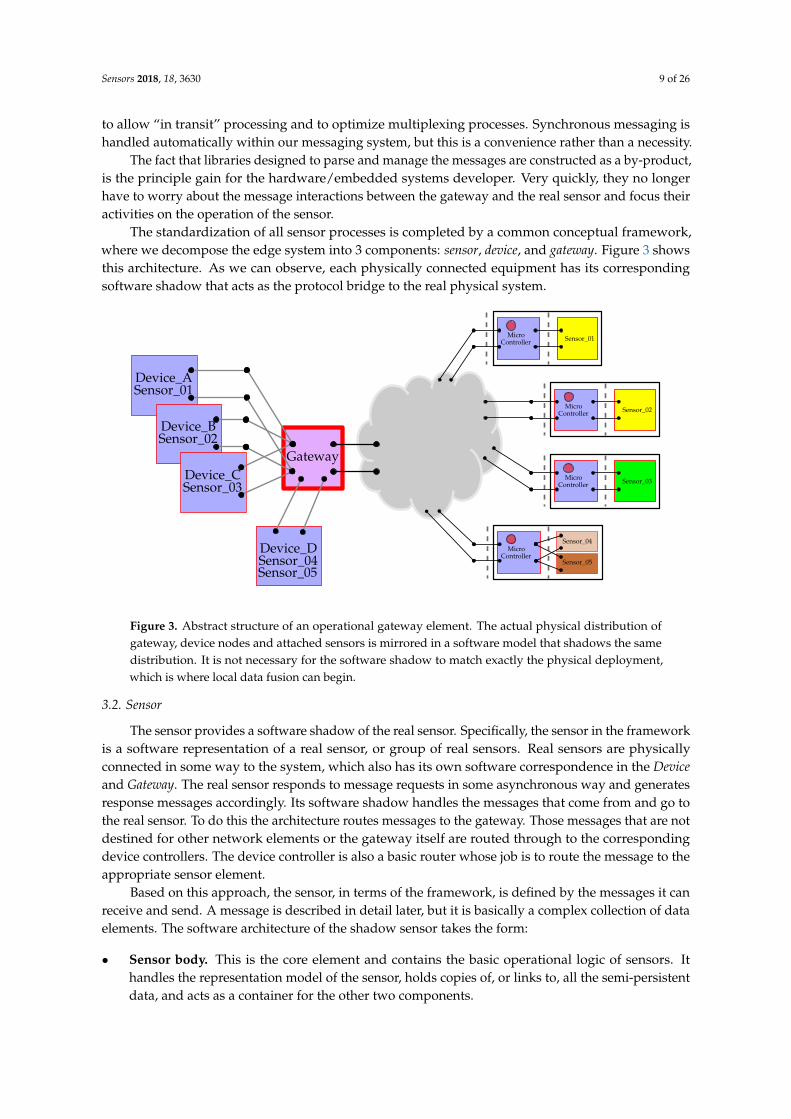
The standardization of all sensor processes is completed by a common conceptual framework,where we decompose the edge system into 3 components: sensor, device, and gateway. Figure 3 showsthis architecture. As we can observe, each physically connected equipment has its correspondingsoftware shadow that acts as the protocol bridge to the real physical system.
Device_DSensor_04
Gateway
Device_ASensor_01
Device_BSensor_02
Device_CSensor_03
Micro Sensor_01Controller
Micro Sensor_02Controller
MicroController
Sensor_04
Sensor_05
Micro Sensor_03Controller
Sensor_05
Figure 3. Abstract structure of an operational gateway element. The actual physical distribution ofgateway, device nodes and attached sensors is mirrored in a software model that shadows the samedistribution. It is not necessary for the software shadow to match exactly the physical deployment,which is where local data fusion can begin.
3.2. Sensor
The sensor provides a software shadow of the real sensor. Specifically, the sensor in the frameworkis a software representation of a real sensor, or group of real sensors. Real sensors are physicallyconnected in some way to the system, which also has its own software correspondence in the Deviceand Gateway. The real sensor responds to message requests in some asynchronous way and generatesresponse messages accordingly. Its software shadow handles the messages that come from and go tothe real sensor. To do this the architecture routes messages to the gateway. Those messages that are notdestined for other network elements or the gateway itself are routed through to the correspondingdevice controllers. The device controller is also a basic router whose job is to route the message to theappropriate sensor element.
Based on this approach, the sensor, in terms of the framework, is defined by the messages it canreceive and send. A message is described in detail later, but it is basically a complex collection of dataelements. The software architecture of the shadow sensor takes the form:
• Sensor body. This is the core element and contains the basic operational logic of sensors. Ithandles the representation model of the sensor, holds copies of, or links to, all the semi-persistentdata, and acts as a container for the other two components.

Sensors 2018, 18, 3630 10 of 26
• Message Processor. This processes the incoming messages and performs any local actionnecessary before the message is transferred to the real sensor. It also converts any messagethat is in the general JSON-based format to the serial format, or vice versa, if necessary.
• Message Handlers. There can be several of these to process the messages generated by the sensorand pass them (or a processed version of them) to the appropriate network connection. It istypically in one of these handlers that the generated message can be transformed into a differentrepresentation. If it is not required such a handler is not included.
According to this architecture, a sensor is described as a software object with its own definition aswe present in Listing 1. We previously stated that both the real sensor and its software shadow have atype, which is defined in terms of the messages it can send and receive. The Message Processor andthe Message Handlers are associated with this type.
Sensors 2018, 18, 5 10 of 26
• Message Processor. This processes the incoming messages and performs any local action necessarybefore the message is transferred to the real sensor. It also converts any message that is in thegeneral JSON-based format to the serial format, or vice versa, if necessary.
• Message Handlers. There can be several of these to process the messages generated by the sensorand pass them (or a processed version of them) to the appropriate network connection. It istypically in one of these handlers that the generated message can be transformed into a differentrepresentation. If it is not required such a handler is not included.
According to this architecture, a sensor is described as a software object with its own definition aswe present in Listing 1. We previously stated that both the real sensor and its software shadow have atype, which is defined in terms of the messages it can send and receive. The Message Processor andthe Message Handlers are associated with this type.
sensor.json
1 {2 "sensor": {3 "id": 35,4 "type": "BT-SCAN.LOCAL.RN-4X",5 "serial_conn": {6 "baud": 115200,7 "driver": "/dev/ttyAMA0"8 },9 "persist": true,
10 "is_local": true,11 "log": true,12 "scan_interval": 5,13 "tx_power": -4,14 "sensor_obj": "es.upm.etsit.i3.sensor.btsniffer.rn4x.sensor.Scanner",15 "msg_proc_obj": "es.upm.etsit.i3.sensor.btsniffer.rn4x.sensor.msg.MessageProcessor",16 "msg_hndls": [17 {18 "obj": "es.upm.etsit.i3.sensor.btsniffer.rn4x.sensor.SonarScanHandler",19 "sender_id": "default"20 },21 {22 "obj": "es.upm.etsit.i3.sensor.btsniffer.rn4x.SonarScanHandler",23 "sender_id": "local_virtual_sensor"24 }25 ],26 }27 }
Listing 1. An example of a sensor definition. It is given a type and defined in terms of core element,message processor, and message handlers.
Making use of the Message Processor on the sensor shadow, any processing module or applicationcan communicate with any real sensor connected to the platform both in an asynchronous or asynchronous way. Even though the real sensors only ever implements asynchronous messaging.Once a message is received on the shadow sensor it can be sent directly to the network through theDevice and Gateway or processed locally by means of a Message Handler. A Message Handler providesspecific functionality to the sensors, which is particularly relevant when dealing with complex sensors.
It should be noted that the sensor described in Listing 1 is a locally defined sensor. Specifically,it is a software sensor designed to run on the local hardware. To that end the definition containsdevice specific information (communications port, module transmission power etc.). Such softwaresensors are typically defined in the gateway specification file, Section 3.4, as they typically only exist atruntime and the gateway needs to know that it has to create them. Alternatively, a physical devicecan implement the sensor. In this case the sensor body is a simple ghost used to route messages toand from the sensor, whilst the handlers are the same. The specific configuration of the sensor isdefined via a sensor factory which instantiates the shadow sensor based on the received sensor typeinformation. Both the software defined sensor and the physical sensor define exactly the same message
Listing 1. An example of a sensor definition. It is given a type and defined in terms of core element,message processor, and message handlers.
Making use of the Message Processor on the sensor shadow, any processing module or applicationcan communicate with any real sensor connected to the platform both in an asynchronous or asynchronous way. Even though the real sensors only ever implements asynchronous messaging.Once a message is received on the shadow sensor it can be sent directly to the network through theDevice and Gateway or processed locally by means of a Message Handler. A Message Handler providesspecific functionality to the sensors, which is particularly relevant when dealing with complex sensors.
It should be noted that the sensor described in Listing 1 is a locally defined sensor. Specifically,it is a software sensor designed to run on the local hardware. To that end the definition containsdevice specific information (communications port, module transmission power etc.). Such softwaresensors are typically defined in the gateway specification file, Section 3.4, as they typically only exist atruntime and the gateway needs to know that it has to create them. Alternatively, a physical devicecan implement the sensor. In this case the sensor body is a simple ghost used to route messages toand from the sensor, whilst the handlers are the same. The specific configuration of the sensor isdefined via a sensor factory which instantiates the shadow sensor based on the received sensor typeinformation. Both the software defined sensor and the physical sensor define exactly the same messagestructures, so the operation of both seem identical to the system. Note, that in the system designed inthis deployment the BT scanner sensor is not implemented as a local device, but as a Cookie device.
Sensors 2018, 18, 3630 11 of 26
3.3. Device
The device represents the controlling element of the system of the sensor. Typically a device hasmany sensors attached and as such we need a corresponding software element that can distinguishand route between them. Most applications are based on a single physical device with multiple sensorsattached. The shadow device acts as an aggregator under an edge-computing approach, providingwhat appears to be a standard routing interface onto a real device element. Consequently, we haveconstructed the Device as a software representation of the highest-level object attached from outsidethe Gateway bridging points.
The Device has three basic functions.
• Routing: The Device is responsible for routing messages between the real sensor and the softwaresensor shadow. It does this by acting as an interface onto the Gateway to which it is attached.
• Type Information Management: All sensors, real or otherwise, are assigned a type descriptionas a unique key defining its operation. As we presented in Section 3.2, within the framework,this key is an index to the message structure used by the sensor. Two different physical sensorsfrom different manufactures that use the same message structure can use the same type key. TheDevice manages the type information, so when a new sensor appears on the Device, it negotiatesdirectly with the sensor to retrieve the type information and construct a corresponding sensorshadow to manage its operation.
• Device Control Functionality: The Device itself can expose some functionality that cuts acrossmultiple sensors. Hence there needs to be message processing functionality in the Device itself.This is done by providing a special sensor allocation, the control sensor, assigned the Sensor ID tothe value 1. This object follows all the rules of a normal sensor and, consequently, also incorporatesthe ability of implementing specific functionalities locally.
All device objects can be thought of as having two sides: the first one connects to the controllingcode of the shadow sensors; the second one links to the network-based servers and processing elements.In general the sensors handle most of the outgoing messages whilst the Device manages the incomingmessages. When messages are directed to a Device (or any sensor on the Device) they are passed toits message processing class. The default construction of a Device object will automatically create themessage processor internally. Its job is simply to route messages to the appropriate sensor and returnany corresponding messages that are constructed.
A special device, known as the Local Device provides support for local implementation of sensors,i.e., software that conforms to a sensor interface, allowing developers to add sensors that interfacedirectly to the gateway hardware, or use their own proprietor protocols for communications. Such asensor as that in Listing 1 would be added to such a local device.
3.4. Gateway
In order to talk to real sensors, the Gateway element contains software components acting asbridging systems for the different types of connection technologies. The framework aims to be agnosticto the different underlying physical technologies and uses the Gateways to provide a standard interfaceonto sensors for sending and receiving messages.
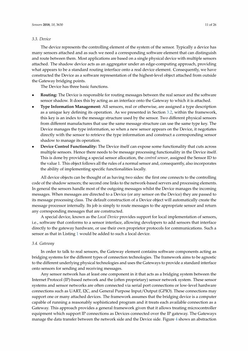
Any sensor network has at least one component in it that acts as a bridging system between theInternet Protocol (IP)-based network and the (often proprietary) sensor network system. These sensorsystems and sensor networks are often connected via serial port connections or low-level hardwareconnections such as UART, I2C, and General Purpose Input/Output (GPIO). These connections maysupport one or many attached devices. The framework assumes that the bridging device is a computercapable of running a reasonably sophisticated program and it treats each available connection as aGateway. This approach provides a general framework given that it allows treating microcontrollerequipment which support IP connections as Devices connected over the IP gateway. The Gatewaysmanage the data transfer between the network side and the Device side. Figure 4 shows an abstraction
Sensors 2018, 18, 3630 12 of 26
of that structure. In this case there are four active gateways attached: a standard USB (Universal SerialBus) port, a USB port connecting a ZigBee network, a UART port, and the local BT chip. When thegateway control system is started, monitoring gateway programs need to be assigned to each of theseports. This is done by providing a gateway mapping file, which defines how each port is allocated.An example of a corresponding mapping file for the Gateway is shown in Listing 2.
USB0Gateway
UART
USB1
BluetoothFigure 4. Hardware model of a gateway is a system with a collection of communication systems.
Sensors 2018, 18, 5 13 of 26
gatewaymap.sndl
1 {2 "gateway_map": [3 {4 "name": "Local_Devices",5 "type": "LOCAL",6 "logical_id": 1,7 "controller": true,8 "devices": [9 {
10 "class_name": "org.simplicis.sndl.lib.local.gateway.LocalDevice",11 "address": {12 "is_mac": false,13 "address": "Local_Devices",14 "type": "LOCAL"15 },16 "logical_id": 1,17 "persist": true,18 "sensors": [19 ]20 }21 ]22 },23 {24 "name": "BT Device",25 "logical_id": 2,26 "type": "Bluetooth",27 },28 {29 "name": "USB_0 Device",30 "logical_id": 3,31 "type": "Zigbee",32 "serial_conn": {33 "baud": 9600,34 "driver": "/dev/ttyUSB0"35 }36 },37 {38 "name": "USB_1 Cookie Gateway",39 "type": "USBCookie",40 "logical_id": 4,41 "serial_conn": {42 "baud": 115200,43 "driver": "/dev/ttyUSB1"44 },45 "devices": [46 ]47 }48 ]49 }
Listing 2. Gateway map definition. Mapping to various communications interfaces onto the correctgateway interfaces.
The configuration information is necessary in reality as there is generally no way to discover whatis on each connection interface. Some systems do provide this information, but it is the exception ratherthan the rule. The implementation of a locally available file is needed to deal with the many errors andnetwork blackouts a system may experience over its years of operation. It can periodically monitor forupdates and changes and bring up to date its local data, but it always has to have something to fallback on if things start to fail.
3.5. Messaging Abstraction
The basis of our integration strategy is extremely simple and comes from the realization thatmessages are independent of the protocol used to represent them. Messages are simply abstractcollections of data that are assigned a name allowing us to distinguish one message type from another.Specifically a message is a map that connects key names, or field identifiers, with values. This meansmessages are free to take different instantiated forms depending on which is the most appropriate forthe given situation. It is easier to demonstrate the flexibility of message representations starting with
Listing 2. Gateway map definition. Mapping to various communications interfaces onto the correctgateway interfaces.
The configuration information is necessary in reality as there is generally no way to discover whatis on each connection interface. Some systems do provide this information, but it is the exception ratherthan the rule. The implementation of a locally available file is needed to deal with the many errors and
Sensors 2018, 18, 3630 13 of 26
network blackouts a system may experience over its years of operation. It can periodically monitor forupdates and changes and bring up to date its local data, but it always has to have something to fallback on if things start to fail.
3.5. Messaging Abstraction
The basis of our integration strategy is extremely simple and comes from the realization thatmessages are independent of the protocol used to represent them. Messages are simply abstractcollections of data that are assigned a name allowing us to distinguish one message type from another.Specifically a message is a map that connects key names, or field identifiers, with values. This meansmessages are free to take different instantiated forms depending on which is the most appropriate forthe given situation. It is easier to demonstrate the flexibility of message representations starting withJSON, because JSON is human readable. However, it is important to realize that our thesis is based onthe fact that messages can take any representation.
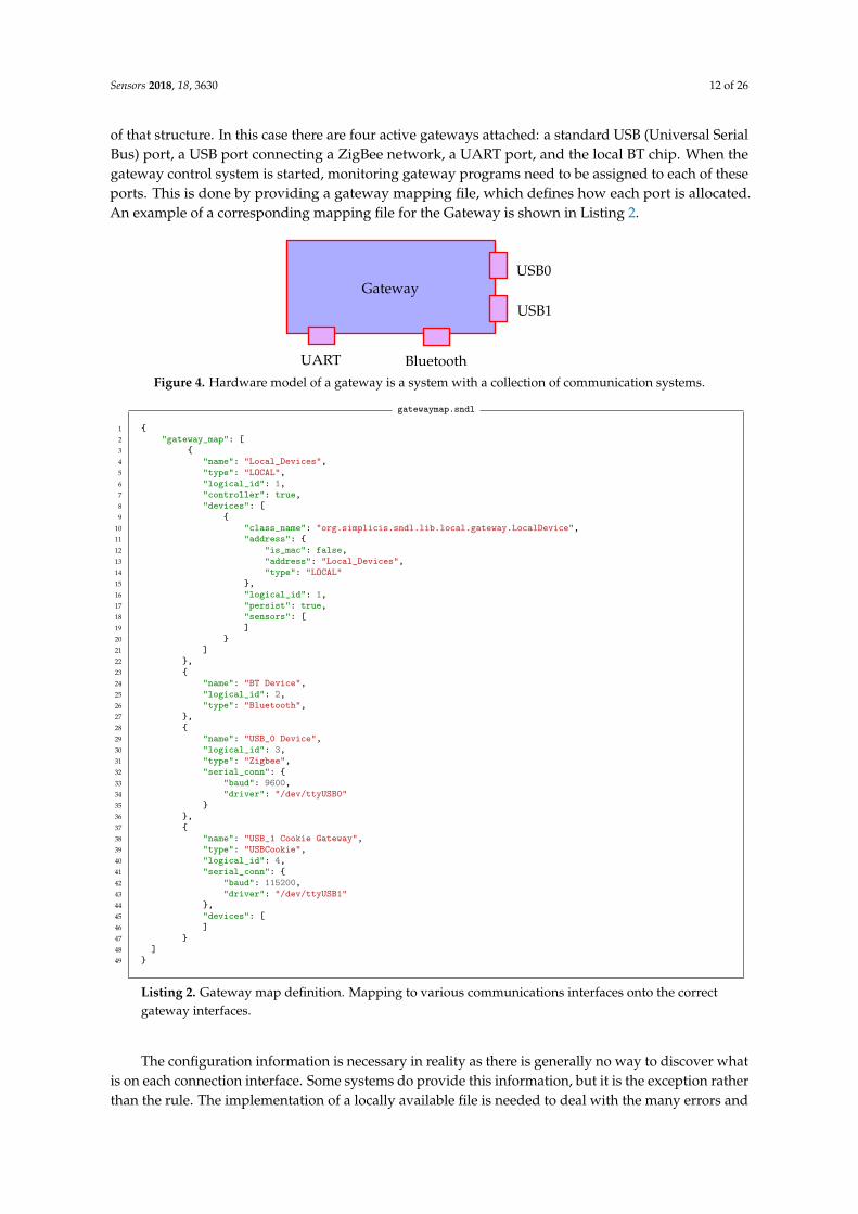
A message can quite naturally take the form of a JSON object, where keys, or names are used tolabel the values. A value of course can be a native data object or another map, or vector, making itpossible to have extremely complex structures. A fundamental observation is that the keys in such anobject are redundant when the structure of the message is known. Hence, the message can easily bereplaced with a much more compact (in general) vector form, where the position of a value implicitlydefined is key. Figure 5 shows two such representations side by side. In the vector representation,missing elements must be represented by empty values to ensure each value is in the correct locationof the vector. For example in Figure 5 the missing data element in the first vector object of the vectorobj_01 is represented by an empty string.
Sensors 2018, 18, 5 14 of 26
JSON, because JSON is human readable. However, it is important to realize that our thesis is based onthe fact that messages can take any representation.
A message can quite naturally take the form of a JSON object, where keys, or names are used tolabel the values. A value of course can be a native data object or another map, or vector, making itpossible to have extremely complex structures. A fundamental observation is that the keys in such anobject are redundant when the structure of the message is known. Hence, the message can easily bereplaced with a much more compact (in general) vector form, where the position of a value implicitlydefined is key. Figure 5 shows two such representations side by side. In the vector representation,missing elements must be represented by empty values to ensure each value is in the correct locationof the vector. For example in Figure 5 the missing data element in the first vector object of the vectorobj_01 is represented by an empty string.
msg-json object
{"tag":"TAG","device_id":"<D_ID>","sensor_id":"value: S_ID","payload":{
"data_01":"STR_01","obj_01":[
{"data_01":"value: D_01"
},{
"data_01":"value: D_02","data_02":"STR_03"
}],"obj_02":{
"data_01":"value: D_03","data_02":"STR_04","data_03":"value: D_04","data_04":"value: D_05",
}}
}
msg-vector object
1 [2 "TAG",3 "<D_ID>",4 "value: S_ID",5 [6 "STR_01",7 [8 [9 "value: D_01",
10 ""11 ],12 [13 "value: D_02",14 "STR_03"15 ]16 ],17 [18 "value: D_03",19 "STR_04",20 "value: D_04",21 "value: D_05",22 ]23 ]24 ]
Figure 5. Messages reduce to maps of data, where each value can be either a native data object, oranother map. However, if the format is known, the map can be replaced as a vector of values, wherethe maps keys are implicitly defined by their location of the vector. Here the equivalent message isshow side by side as a JSON object representation and its associated vector representation.
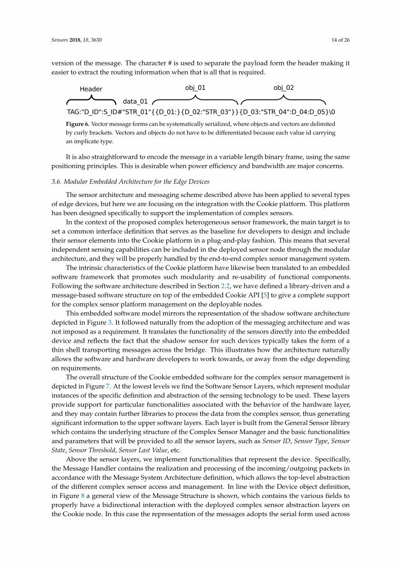
Extending the concept of vectorisation, it is a simple matter to represent the message as a serialstring. Each message becomes a string, terminated with a null character. Native data objects areseparated with the: character. Objects and vectors are delimited by curly brackets {. . .}. It is notnecessary to distinguish between objects and vectors as each message carries a type and therefore thetype of each object is implicitly known. Figure 6 demonstrates how the message in Figure 5 transposesinto a serial form. Each of the major parts are marked to indicate how they relate to the original mapversion of the message. The character # is used to separate the payload form the header making iteasier to extract the routing information when that is all that is required.
Figure 6. Vector message forms can be systematically serialized, where objects and vectors are delimitedby curly brackets. Vectors and objects do not have to be differentiated because each value id carryingan implicate type.
It is also straightforward to encode the message in a variable length binary frame, using the samepositioning principles. This is desirable when power efficiency and bandwidth are major concerns.
Figure 5. Messages reduce to maps of data, where each value can be either a native data object, oranother map. However, if the format is known, the map can be replaced as a vector of values, wherethe maps keys are implicitly defined by their location of the vector. Here the equivalent message isshow side by side as a JSON object representation and its associated vector representation.
Extending the concept of vectorisation, it is a simple matter to represent the message as a serialstring. Each message becomes a string, terminated with a null character. Native data objects areseparated with the: character. Objects and vectors are delimited by curly brackets {. . .}. It is notnecessary to distinguish between objects and vectors as each message carries a type and therefore thetype of each object is implicitly known. Figure 6 demonstrates how the message in Figure 5 transposesinto a serial form. Each of the major parts are marked to indicate how they relate to the original map
Sensors 2018, 18, 3630 14 of 26
version of the message. The character # is used to separate the payload form the header making iteasier to extract the routing information when that is all that is required.
Figure 6. Vector message forms can be systematically serialized, where objects and vectors are delimitedby curly brackets. Vectors and objects do not have to be differentiated because each value id carryingan implicate type.
It is also straightforward to encode the message in a variable length binary frame, using the samepositioning principles. This is desirable when power efficiency and bandwidth are major concerns.
3.6. Modular Embedded Architecture for the Edge Devices
The sensor architecture and messaging scheme described above has been applied to several typesof edge devices, but here we are focusing on the integration with the Cookie platform. This platformhas been designed specifically to support the implementation of complex sensors.
In the context of the proposed complex heterogeneous sensor framework, the main target is toset a common interface definition that serves as the baseline for developers to design and includetheir sensor elements into the Cookie platform in a plug-and-play fashion. This means that severalindependent sensing capabilities can be included in the deployed sensor node through the modulararchitecture, and they will be properly handled by the end-to-end complex sensor management system.
The intrinsic characteristics of the Cookie platform have likewise been translated to an embeddedsoftware framework that promotes such modularity and re-usability of functional components.Following the software architecture described in Section 2.2, we have defined a library-driven and amessage-based software structure on top of the embedded Cookie API [5] to give a complete supportfor the complex sensor platform management on the deployable nodes.
This embedded software model mirrors the representation of the shadow software architecturedepicted in Figure 3. It followed naturally from the adoption of the messaging architecture and wasnot imposed as a requirement. It translates the functionality of the sensors directly into the embeddeddevice and reflects the fact that the shadow sensor for such devices typically takes the form of athin shell transporting messages across the bridge. This illustrates how the architecture naturallyallows the software and hardware developers to work towards, or away from the edge dependingon requirements.
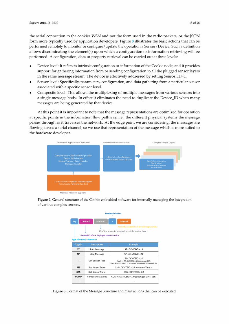
The overall structure of the Cookie embedded software for the complex sensor management isdepicted in Figure 7. At the lowest levels we find the Software Sensor Layers, which represent modularinstances of the specific definition and abstraction of the sensing technology to be used. These layersprovide support for particular functionalities associated with the behavior of the hardware layer,and they may contain further libraries to process the data from the complex sensor, thus generatingsignificant information to the upper software layers. Each layer is built from the General Sensor librarywhich contains the underlying structure of the Complex Sensor Manager and the basic functionalitiesand parameters that will be provided to all the sensor layers, such as Sensor ID, Sensor Type, SensorState, Sensor Threshold, Sensor Last Value, etc.
Above the sensor layers, we implement functionalities that represent the device. Specifically,the Message Handler contains the realization and processing of the incoming/outgoing packets inaccordance with the Message System Architecture definition, which allows the top-level abstractionof the different complex sensor access and management. In line with the Device object definition,in Figure 8 a general view of the Message Structure is shown, which contains the various fields toproperly have a bidirectional interaction with the deployed complex sensor abstraction layers onthe Cookie node. In this case the representation of the messages adopts the serial form used across
Sensors 2018, 18, 3630 15 of 26
the serial connection to the cookies WSN and not the form used in the radio packets, or the JSONform more typically used by application developers. Figure 8 illustrates the basic actions that can beperformed remotely to monitor or configure/update the operation a Sensor/Device. Such a definitionallows discriminating the element(s) upon which a configuration or information retrieving will beperformed. A configuration, data or property retrieval can be carried out at three levels:
• Device level: It refers to intrinsic configuration or information of the Cookie node, and it providessupport for gathering information from or sending configuration to all the plugged sensor layersin the same message stream. The device is effectively addressed by setting Sensor_ID=1.
• Sensor level: Specifically, parameters, configuration, and data gathering from a particular sensorassociated with a specific sensor level.
• Composite level: This allows the multiplexing of multiple messages from various sensors intoa single message body. In effect it eliminates the need to duplicate the Device_ID when manymessages are being generated by that device.
At this point it is important to note that the message representations are optimized for operationat specific points in the information flow pathway, i.e., the different physical systems the messagepasses through as it traverses the network. At the edge point we are considering, the messages areflowing across a serial channel, so we use that representation of the message which is more suited tothe hardware developer.
Complex Sensor Platform ConfigurationSensor Initialization
Sensor Process – Event HandlerMessage Handler
Cookie HW/SW Integration Platform Support(Libraries and Functional Add-Ons)
Generic Interface FunctionsGeneral Sensor Object Structure
Embedded Application - Top-Level Complex Sensor LayersGeneral Sensor Abstraction
Specific Sensor OperationData Structures
Sensor Interface FunctionsSensor Handler
Modular Platform Support
Figure 7. General structure of the Cookie embedded software for internally managing the integrationof various complex sensors.
Type of action/information
General ID of the deployed remote device
ID of the sensor to be acted on or information from
Related parameters of the message/service
Header delimiter
Tag ID Description Example
ST Start Message ST:<DEVICEID>:1#
SP Stop Message SP:<DEVICEID>:2#
TI Get Sensor TypeTI:<DEVICEID>:1#
(Reply -> TT:<DEVICEID>:1#’cookie.wsn’{‘BT-SCAN.REMOTE.RN4X’:2’}{‘RADAR_B015.REMOTE.COUNT’:3})
SSS Set Sensor State SSS:<DEVICEID>:2#::<IntervalTime>:
GSS Get Sensor State GSS:<DEVICEID>:2#
COMP Compound Actions COMP:<DEVICEID>:1##{ST:2#}{SP:3#}{TI:1#}
…. …. ….
Tag Device ID Sensor ID # Payload
Figure 8. Format of the Message Structure and main actions that can be executed.
Sensors 2018, 18, 3630 16 of 26
4. Real Use Case: Bluetooth Identifier and Radar Counter
Following the proposed development framework we have built an integrated traffic sensor thatcombines a radar counter and a BT identifier to provide complementary traffic information.
4.1. Radar Counter
The radar sensor used in our integrated platform has been implemented on a single PrintedCircuit Board (PCB) following the Cookie architecture. Radar signals are generated and received by theradar transceiver K-LC5 from RF beam [23]. It is a low-cost wide-beam transceiver which continuouslygenerates 24.150 GHz signals when powered-on, and provides the mixed I and Q signals returned.The amplitude of these signals is small, so an amplifier stage is used in our board to amplify them.In addition, an anti-aliasing filter and a single-ended to differential converter are implemented toadapt the I and Q signals before digitalizing them.
The integrated analog to digital converters (ADCs) included in the STM32L496 microcontrollerare used to digitize the returned signals. These 12-bit ADCs perform simultaneous acquisition mode tosample I and Q signals. In addition, the oversampling hardware engine is used to increase the effectiveresolution to 16 bits. The acquired samples are then stored in the microcontroller memory by usingdirect memory access (DMA). The microcontroller used runs up to 80 MHz of clock frequency andincludes a floating point unit which allows using it to process the stored samples and provide countingdata. These generated data are sent to the processing layer when they are requested using a slaveSPI interface.
Finally, the low-noise requirements of the radar hardware make it necessary to implement anindependent power supply module instead of using the Cookie power supply framework. This moduleprovides independent supply voltages for the analog and digital modules. The radar transceiver, theamplification and filtering modules are powered by the analog supply which provides enough currentfor them with small ripple, as high ripple values reduce acquisition performance.
4.2. Bluetooth Identifier
The variation on the BT scanner designed for this type of deployment uses a standard BT module,the Microchip RN41 [24], which features a low-power certified Class 1 BT Radio with on-boardembedded stack, and with a UART interface. This has proved to have sufficient processing speed todeal with scanning for vehicles moving with a high velocity. Similar to the radar-based sensor layer,the BT identifier has been designed following the modular architecture of the Cookie presented inprevious sections.
Seeking the desired plug-and-play capability a small dedicated program converts the propitiatoryserial protocol into the message structure for a location scanner. In this case the system transparentlysees the Cookie as a device regardless as to whether the Cookie is connected as a serial device, or viathe sensor network.
4.3. Information Flow within the Hardware
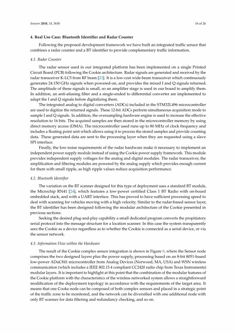
The result of the Cookie complex sensor integration is shown in Figure 9, where the Sensor nodecomprises the two designed layers plus the power supply, processing based on an 8-bit 8051-basedlow-power ADuC841 microcontroller from Analog Devices (Norwood, MA, USA) and WSN wirelesscommunication (which includes a IEEE 802.15.4 compliant CC2420 radio chip from Texas Instruments)modular layers. It is important to highlight at this point that the combination of the modular features ofthe Cookie platform with the characteristics of the wireless networked system allows a straightforwardmodification of the deployment topology in accordance with the requirements of the target area. Itmeans that one Cooke node can be composed of both complex sensors and placed in a strategic pointof the traffic zone to be monitored, and the network can be diversified with one additional node withonly BT scanner for data filtering and redundancy checking, and so on.
Sensors 2018, 18, 3630 17 of 26
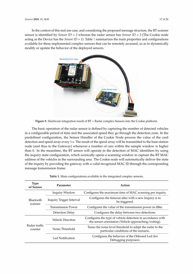
In the context of this real use case, and considering the proposed message structure, the BT scannersensor is identified by Sensor ID = 2 whereas the radar sensor has Sensor ID = 3 (The Cookie nodeacting as the Device has the Sensor ID = 1). Table 1 summarizes the main properties and configurationsavailable for these implemented complex sensors that can be remotely accessed, so as to dynamicallymodify or update the behavior of the deployed sensors.
Figure 9. Hardware integration result of BT + Radar complex Sensors into the Cookie platform.
The basic operation of the radar sensor is defined by capturing the number of detected vehiclesin a configurable period of time and the associated speed they go through the detection zone. In thepredefined configuration, the Sensor Handler of the Cookie Node process the value of the carddetection and speed array every 1 s. The result of the speed array will be transmitted to the base-stationnode (and thus to the Gateway) whenever a number of cars within the sample window is higherthan 0. In the meantime, the BT sensor will operate in the detection of MAC identifiers by usingthe inquiry state configuration, which scenically opens a scanning window to capture the BT MACaddress of the vehicles in the surrounding area. The Cookie node will automatically deliver the stateof the inquiry by providing the gateway with a valid recognized MAC ID through the correspondingmessage transmission frame.
Table 1. Main configurations available in the integrated complex sensors.
Typeof Sensor Parameter Action
Bluetoothscanner
Inquiry Window Configures the maximum time of MAC scanning per inquiry.
Inquiry Trigger IntervalConfigures the timeout after with a new Inquiry is to
be triggered.
Transmission Power Configures the value of the transmission power in dBm.
Detection Delay Configures the delay between two detections.
Radar trafficcounter
Vehicle DirectionConfigures the type of vehicle detection in accordance with
the sensor orientation (Vehicle approaching/exiting).
Noise ThresholdTunes the noise level threshold to adapt the radar to the
particular conditions of the scenario.
Led NotificationConfigures the behavior of the Onboard Led (for
Debugging purposes).
Sensors 2018, 18, 3630 18 of 26
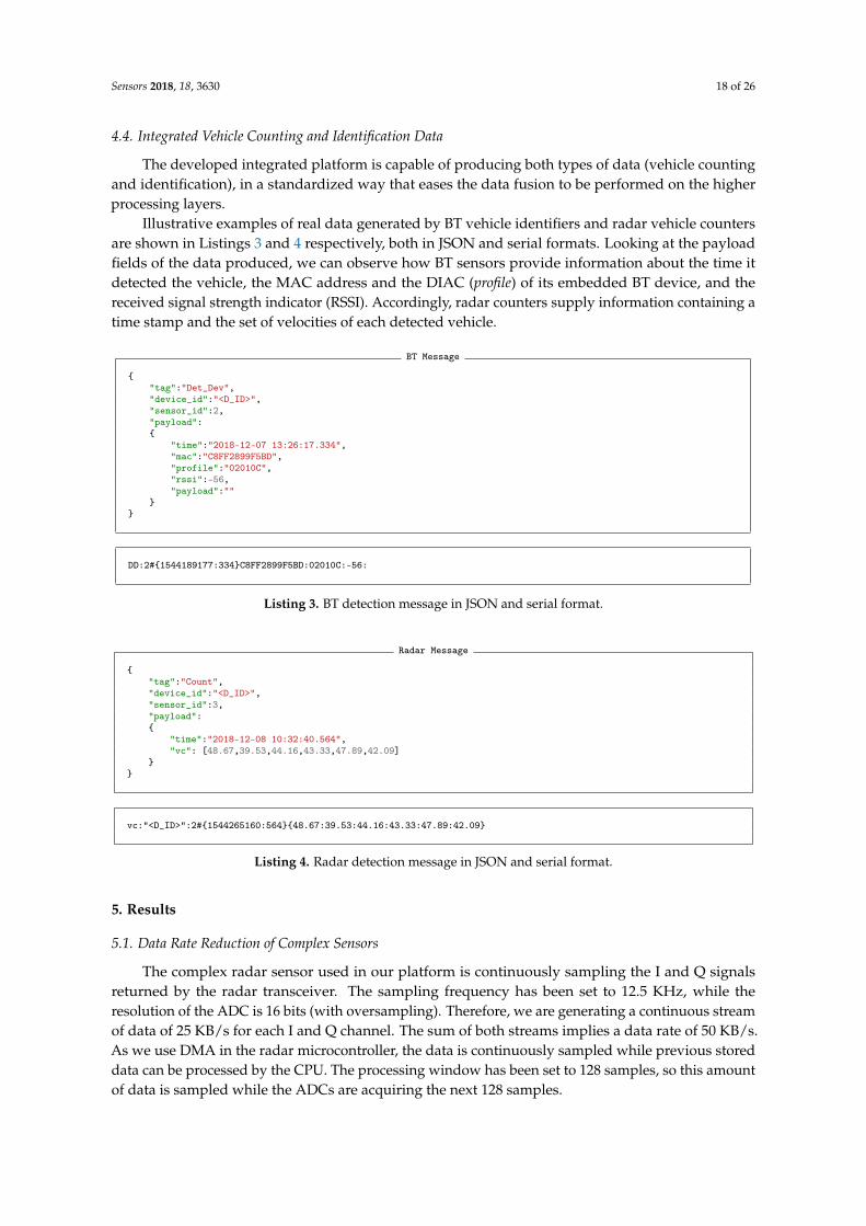
4.4. Integrated Vehicle Counting and Identification Data
The developed integrated platform is capable of producing both types of data (vehicle countingand identification), in a standardized way that eases the data fusion to be performed on the higherprocessing layers.
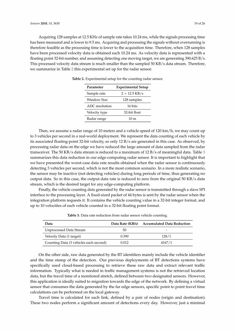
Illustrative examples of real data generated by BT vehicle identifiers and radar vehicle countersare shown in Listings 3 and 4 respectively, both in JSON and serial formats. Looking at the payloadfields of the data produced, we can observe how BT sensors provide information about the time itdetected the vehicle, the MAC address and the DIAC (profile) of its embedded BT device, and thereceived signal strength indicator (RSSI). Accordingly, radar counters supply information containing atime stamp and the set of velocities of each detected vehicle.
Sensors 2018, 18, 5 19 of 26
fields of the data produced, we can observe how BT sensors provide information about the time itdetected the vehicle, the MAC address and the DIAC (profile) of its embedded BT device, and thereceived signal strength indicator (RSSI). Accordingly, radar counters supply information containing atime stamp and the set of velocities of each detected vehicle.
BT Message
{"tag":"Det_Dev","device_id":"<D_ID>","sensor_id":2,"payload":{
"time":"2018-12-07 13:26:17.334","mac":"C8FF2899F5BD","profile":"02010C","rssi":-56,"payload":""
}}
DD:2#{1544189177:334}C8FF2899F5BD:02010C:-56:
Listing 3. BT detection message in JSON and serial format.
Radar Message
{"tag":"Count","device_id":"<D_ID>","sensor_id":3,"payload":{
"time":"2018-12-08 10:32:40.564","vc": [48.67,39.53,44.16,43.33,47.89,42.09]
}}
vc:"<D_ID>":2#{1544265160:564}{48.67:39.53:44.16:43.33:47.89:42.09}
Listing 4. Radar detection message in JSON and serial format.
5. Results
5.1. Data Rate Reduction of Complex Sensors
The complex radar sensor used in our platform is continuously sampling the I and Q signalsreturned by the radar transceiver. The sampling frequency has been set to 12.5 KHz, while theresolution of the ADC is 16 bits (with oversampling). Therefore, we are generating a continuous streamof data of 25 KB/s for each I and Q channel. The sum of both streams implies a data rate of 50 KB/s.As we use DMA in the radar microcontroller, the data is continuously sampled while previous storeddata can be processed by the CPU. The processing window has been set to 128 samples, so this amountof data is sampled while the ADCs are acquiring the next 128 samples.
Acquiring 128 samples at 12.5 KHz of sample rate takes 10.24 ms, while the signals processing timehas been measured and is lower to 9.5 ms. Acquiring and processing the signals without overrunningis therefore feasible as the processing time is lower to the acquisition time. Therefore, when 128samples have been processed velocity data is obtained each 10.24 ms. As velocity data is representedwith a floating point 32-bit number, and assuming detecting one moving target, we are generating390.625 B/s. This processed velocity data stream is much smaller than the sampled 50 KB/s datastream. Therefore, we summarize in Table 2 this experimental set up for the radar sensor.
Listing 3. BT detection message in JSON and serial format.
Sensors 2018, 18, 5 19 of 26
fields of the data produced, we can observe how BT sensors provide information about the time itdetected the vehicle, the MAC address and the DIAC (profile) of its embedded BT device, and thereceived signal strength indicator (RSSI). Accordingly, radar counters supply information containing atime stamp and the set of velocities of each detected vehicle.
BT Message
{"tag":"Det_Dev","device_id":"<D_ID>","sensor_id":2,"payload":{
"time":"2018-12-07 13:26:17.334","mac":"C8FF2899F5BD","profile":"02010C","rssi":-56,"payload":""
}}
DD:2#{1544189177:334}C8FF2899F5BD:02010C:-56:
Listing 3. BT detection message in JSON and serial format.
Radar Message
{"tag":"Count","device_id":"<D_ID>","sensor_id":3,"payload":{
"time":"2018-12-08 10:32:40.564","vc": [48.67,39.53,44.16,43.33,47.89,42.09]
}}
vc:"<D_ID>":2#{1544265160:564}{48.67:39.53:44.16:43.33:47.89:42.09}
Listing 4. Radar detection message in JSON and serial format.
5. Results
5.1. Data Rate Reduction of Complex Sensors
The complex radar sensor used in our platform is continuously sampling the I and Q signalsreturned by the radar transceiver. The sampling frequency has been set to 12.5 KHz, while theresolution of the ADC is 16 bits (with oversampling). Therefore, we are generating a continuous streamof data of 25 KB/s for each I and Q channel. The sum of both streams implies a data rate of 50 KB/s.As we use DMA in the radar microcontroller, the data is continuously sampled while previous storeddata can be processed by the CPU. The processing window has been set to 128 samples, so this amountof data is sampled while the ADCs are acquiring the next 128 samples.
Acquiring 128 samples at 12.5 KHz of sample rate takes 10.24 ms, while the signals processing timehas been measured and is lower to 9.5 ms. Acquiring and processing the signals without overrunningis therefore feasible as the processing time is lower to the acquisition time. Therefore, when 128samples have been processed velocity data is obtained each 10.24 ms. As velocity data is representedwith a floating point 32-bit number, and assuming detecting one moving target, we are generating390.625 B/s. This processed velocity data stream is much smaller than the sampled 50 KB/s datastream. Therefore, we summarize in Table 2 this experimental set up for the radar sensor.
Listing 4. Radar detection message in JSON and serial format.
5. Results
5.1. Data Rate Reduction of Complex Sensors
The complex radar sensor used in our platform is continuously sampling the I and Q signalsreturned by the radar transceiver. The sampling frequency has been set to 12.5 KHz, while theresolution of the ADC is 16 bits (with oversampling). Therefore, we are generating a continuous streamof data of 25 KB/s for each I and Q channel. The sum of both streams implies a data rate of 50 KB/s.As we use DMA in the radar microcontroller, the data is continuously sampled while previous storeddata can be processed by the CPU. The processing window has been set to 128 samples, so this amountof data is sampled while the ADCs are acquiring the next 128 samples.
Sensors 2018, 18, 3630 19 of 26
Acquiring 128 samples at 12.5 KHz of sample rate takes 10.24 ms, while the signals processing timehas been measured and is lower to 9.5 ms. Acquiring and processing the signals without overrunning istherefore feasible as the processing time is lower to the acquisition time. Therefore, when 128 sampleshave been processed velocity data is obtained each 10.24 ms. As velocity data is represented with afloating point 32-bit number, and assuming detecting one moving target, we are generating 390.625 B/s.This processed velocity data stream is much smaller than the sampled 50 KB/s data stream. Therefore,we summarize in Table 2 this experimental set up for the radar sensor.
Table 2. Experimental setup for the counting radar sensor.
Parameter Experimental Setup
Sample rate 2 × 12.5 KB/s
Window Size 128 samples
ADC resolution 16 bits
Velocity type 32-bit float
Radar range 10 m
Then, we assume a radar range of 10 meters and a vehicle speed of 120 km/h, we may count upto 3 vehicles per second in a real-world deployment. We represent the data counting of each vehicle byits associated floating-point 32-bit velocity, so only 12 B/s are generated in this case. As observed, byprocessing radar data on the edge we have reduced the large amount of data sampled from the radartransceiver. The 50 KB/s data stream is reduced to a maximum of 12 B/s of meaningful data. Table 3summarizes this data reduction in our edge-computing radar sensor. It is important to highlight thatwe have presented the worst-case data rate results obtained when the radar sensor is continuouslydetecting 3 vehicles per second, which is not the most common scenario. In a more realistic scenario,the sensor may be inactive (not detecting vehicles) during long periods of time, thus generating nooutput data. So in this case, the output data rate is reduced to zero from the original 50 KB/s datastream, which is the desired target for any edge-computing platform.
Finally, the vehicle counting data generated by the radar sensor is transmitted through a slave SPIinterface to the processing layer. A fixed-sized packet of 44 bytes is sent by the radar sensor when theintegration platform requests it. It contains the vehicle counting value in a 32-bit integer format, andup to 10 velocities of each vehicle counted in a 32-bit floating point format.
Table 3. Data rate reduction from radar sensor vehicle counting.
Data Data Rate (KB/s) Accumulated Data Reduction
Unprocessed Data Stream 50 -
Velocity Data (1 target) 0.390 128/1
Counting Data (3 vehicles each second) 0.012 4167/1
On the other side, raw data generated by the BT identifiers mainly include the vehicle identifierand the time stamp of the detection. Our previous deployments of BT detections systems havespecifically used cloud-based processing to retrieve these raw data and extract relevant trafficinformation. Typically what is needed in traffic management systems is not the retrieved locationdata, but the travel time of a monitored stretch, defined between two designated sensors. However,this application is ideally suited to migration towards the edge of the network. By defining a virtualsensor that consumes the data generated by the far edge sensors, specific point to point travel timecalculations can be performed on the local gateway.
Travel time is calculated for each link, defined by a pair of nodes (origin and destination).These two nodes perform a significant amount of detections every day. However, just a minimal
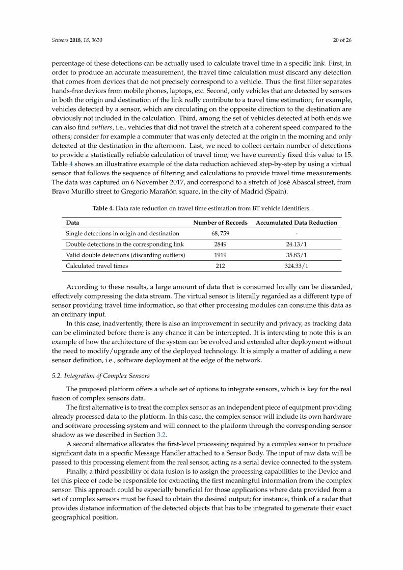
Sensors 2018, 18, 3630 20 of 26
percentage of these detections can be actually used to calculate travel time in a specific link. First, inorder to produce an accurate measurement, the travel time calculation must discard any detectionthat comes from devices that do not precisely correspond to a vehicle. Thus the first filter separateshands-free devices from mobile phones, laptops, etc. Second, only vehicles that are detected by sensorsin both the origin and destination of the link really contribute to a travel time estimation; for example,vehicles detected by a sensor, which are circulating on the opposite direction to the destination areobviously not included in the calculation. Third, among the set of vehicles detected at both ends wecan also find outliers, i.e., vehicles that did not travel the stretch at a coherent speed compared to theothers; consider for example a commuter that was only detected at the origin in the morning and onlydetected at the destination in the afternoon. Last, we need to collect certain number of detectionsto provide a statistically reliable calculation of travel time; we have currently fixed this value to 15.Table 4 shows an illustrative example of the data reduction achieved step-by-step by using a virtualsensor that follows the sequence of filtering and calculations to provide travel time measurements.The data was captured on 6 November 2017, and correspond to a stretch of José Abascal street, fromBravo Murillo street to Gregorio Marañón square, in the city of Madrid (Spain).
Table 4. Data rate reduction on travel time estimation from BT vehicle identifiers.
Data Number of Records Accumulated Data Reduction
Single detections in origin and destination 68, 759 -
Double detections in the corresponding link 2849 24.13/1
Valid double detections (discarding outliers) 1919 35.83/1
Calculated travel times 212 324.33/1
According to these results, a large amount of data that is consumed locally can be discarded,effectively compressing the data stream. The virtual sensor is literally regarded as a different type ofsensor providing travel time information, so that other processing modules can consume this data asan ordinary input.
In this case, inadvertently, there is also an improvement in security and privacy, as tracking datacan be eliminated before there is any chance it can be intercepted. It is interesting to note this is anexample of how the architecture of the system can be evolved and extended after deployment withoutthe need to modify/upgrade any of the deployed technology. It is simply a matter of adding a newsensor definition, i.e., software deployment at the edge of the network.
5.2. Integration of Complex Sensors
The proposed platform offers a whole set of options to integrate sensors, which is key for the realfusion of complex sensors data.
The first alternative is to treat the complex sensor as an independent piece of equipment providingalready processed data to the platform. In this case, the complex sensor will include its own hardwareand software processing system and will connect to the platform through the corresponding sensorshadow as we described in Section 3.2.
A second alternative allocates the first-level processing required by a complex sensor to producesignificant data in a specific Message Handler attached to a Sensor Body. The input of raw data will bepassed to this processing element from the real sensor, acting as a serial device connected to the system.
Finally, a third possibility of data fusion is to assign the processing capabilities to the Device andlet this piece of code be responsible for extracting the first meaningful information from the complexsensor. This approach could be especially beneficial for those applications where data provided from aset of complex sensors must be fused to obtain the desired output; for instance, think of a radar thatprovides distance information of the detected objects that has to be integrated to generate their exactgeographical position.
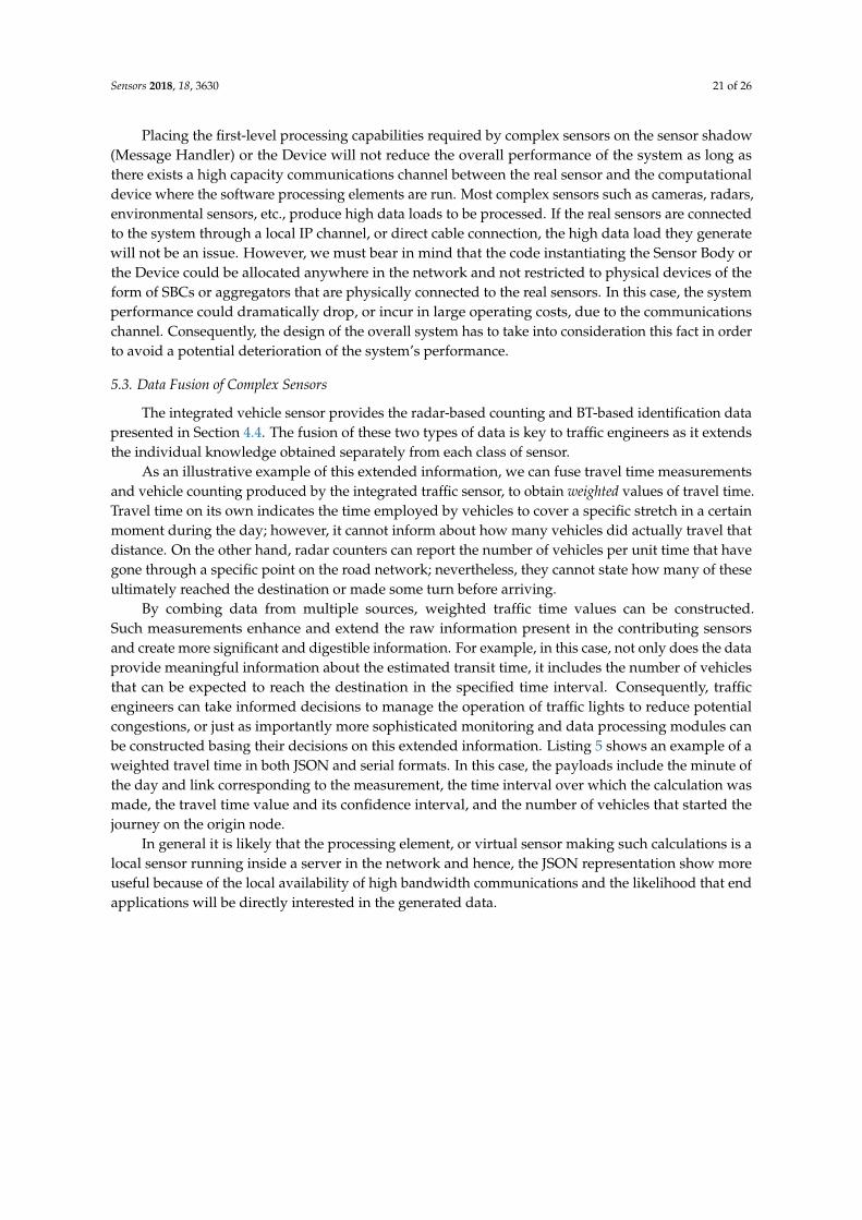
Sensors 2018, 18, 3630 21 of 26
Placing the first-level processing capabilities required by complex sensors on the sensor shadow(Message Handler) or the Device will not reduce the overall performance of the system as long asthere exists a high capacity communications channel between the real sensor and the computationaldevice where the software processing elements are run. Most complex sensors such as cameras, radars,environmental sensors, etc., produce high data loads to be processed. If the real sensors are connectedto the system through a local IP channel, or direct cable connection, the high data load they generatewill not be an issue. However, we must bear in mind that the code instantiating the Sensor Body orthe Device could be allocated anywhere in the network and not restricted to physical devices of theform of SBCs or aggregators that are physically connected to the real sensors. In this case, the systemperformance could dramatically drop, or incur in large operating costs, due to the communicationschannel. Consequently, the design of the overall system has to take into consideration this fact in orderto avoid a potential deterioration of the system’s performance.
5.3. Data Fusion of Complex Sensors
The integrated vehicle sensor provides the radar-based counting and BT-based identification datapresented in Section 4.4. The fusion of these two types of data is key to traffic engineers as it extendsthe individual knowledge obtained separately from each class of sensor.
As an illustrative example of this extended information, we can fuse travel time measurementsand vehicle counting produced by the integrated traffic sensor, to obtain weighted values of travel time.Travel time on its own indicates the time employed by vehicles to cover a specific stretch in a certainmoment during the day; however, it cannot inform about how many vehicles did actually travel thatdistance. On the other hand, radar counters can report the number of vehicles per unit time that havegone through a specific point on the road network; nevertheless, they cannot state how many of theseultimately reached the destination or made some turn before arriving.
By combing data from multiple sources, weighted traffic time values can be constructed.Such measurements enhance and extend the raw information present in the contributing sensorsand create more significant and digestible information. For example, in this case, not only does the dataprovide meaningful information about the estimated transit time, it includes the number of vehiclesthat can be expected to reach the destination in the specified time interval. Consequently, trafficengineers can take informed decisions to manage the operation of traffic lights to reduce potentialcongestions, or just as importantly more sophisticated monitoring and data processing modules canbe constructed basing their decisions on this extended information. Listing 5 shows an example of aweighted travel time in both JSON and serial formats. In this case, the payloads include the minute ofthe day and link corresponding to the measurement, the time interval over which the calculation wasmade, the travel time value and its confidence interval, and the number of vehicles that started thejourney on the origin node.
In general it is likely that the processing element, or virtual sensor making such calculations is alocal sensor running inside a server in the network and hence, the JSON representation show moreuseful because of the local availability of high bandwidth communications and the likelihood that endapplications will be directly interested in the generated data.
Sensors 2018, 18, 3630 22 of 26
Sensors 2018, 18, 5 22 of 26
form of SBCs or aggregators that are physically connected to the real sensors. In this case, the systemperformance could dramatically drop, or incur in large operating costs, due to the communicationschannel. Consequently, the design of the overall system has to take into consideration this fact in orderto avoid a potential deterioration of the system’s performance.
5.3. Data Fusion of Complex Sensors
The integrated vehicle sensor provides the radar-based counting and BT-based identification datapresented in Section 4.4. The fusion of these two types of data is key to traffic engineers as it extendsthe individual knowledge obtained separately from each class of sensor.
As an illustrative example of this extended information, we can fuse travel time measurementsand vehicle counting produced by the integrated traffic sensor, to obtain weighted values of travel time.Travel time on its own indicates the time employed by vehicles to cover a specific stretch in a certainmoment during the day; however, it cannot inform about how many vehicles did actually travel thatdistance. On the other hand, radar counters can report the number of vehicles per unit time that havegone through a specific point on the road network; nevertheless, they cannot state how many of theseultimately reached the destination or made some turn before arriving.
By combing data from multiple sources, weighted traffic time values can be constructed.Such measurements enhance and extend the raw information present in the contributing sensorsand create more significant and digestible information. For example, in this case, not only does the dataprovide meaningful information about the estimated transit time, it includes the number of vehiclesthat can be expected to reach the destination in the specified time interval. Consequently, trafficengineers can take informed decisions to manage the operation of traffic lights to reduce potentialcongestions, or just as importantly more sophisticated monitoring and data processing modules canbe constructed basing their decisions on this extended information. Listing 5 shows an example of aweighted travel time in both JSON and serial formats. In this case, the payloads include the minute ofthe day and link corresponding to the measurement, the time interval over which the calculation wasmade, the travel time value and its confidence interval, and the number of vehicles that started thejourney on the origin node.
Travel Time Message
{"tag":"travel_time","device_id":"<D_ID>","sensor_id":2,"payload":{
"time":"2018-12-07 13:26:17.334","link_id":8,"interval":60,"tt":432,"tt_max":515,"tt_min":432,"num_veh":142
}}
TT:2#{1544189177:334}8:60:432:515:432:142
Listing 5. Weighted travel time message in JSON and serial format.
In general it is likely that the processing element, or virtual sensor making such calculations is alocal sensor running inside a server in the network and hence, the JSON representation show moreuseful because of the local availability of high bandwidth communications and the likelihood that endapplications will be directly interested in the generated data.
Listing 5. Weighted travel time message in JSON and serial format.
5.4. Optimization of the Network Overhead for the Data Fusion
Figure 10 shows a comparison of the traffic overhead on the IoT Edge when applying anoptimized compressed binary format for the data fusion of complex sensors and the serialized objectrepresentation. It encounters the transmission of 50 packets from the Sensor Node to the Gatewayusing one single hop and two hops. I can be clearly seen that as the depth of the network increases(number of hops from the edge sensors to the gateway) the difference between the compressedbinary format dramatically reduced the traffic overhead compared to the normal transmission(91.67% of optimization), so the long-term network lifetime will be indeed enhanced with thatadditional enhancement.
Figure 10. Comparison of network overhead for two different types of data fusion transmission formats.
5.5. Reduction of Development Times
The integration of new complex sensors by means of the proposed end-to-end architecture, andparticularly at hardware level by using the Cookie modular platform, allowed reducing developmenttime of each multidisciplinary team, highlighting three main aspects:
• Independent hardware design and implementation: The modularity of the Cookie architectureaccelerated the effective inclusion of the two complex sensors for this real use case. This
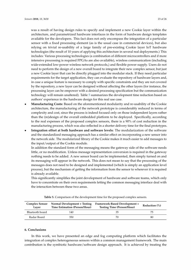
Sensors 2018, 18, 3630 23 of 26
was a result of having design rules to specify and implement a new Cookie layer within thearchitecture, and parametrized hardware interfaces in the form of hardware design templatesavailable for the developers. This fact does not only encompass the integration of a particularsensor with a fixed processing element (as is the usual case in commercial devices), but alsorelying on trivial re-usability of a large family of pre-existing Cookie layer IoT hardwaretechnologies (the result of 10 years of applying this architecture in several real deployments.) Thisincludes: Various processing technologies (a combination of different microcontrollers and if moreintensive processing is required FPGAs are also available), wireless communication (includingwide-extended low-power wireless network protocols,) and flexible power supply. Users do notneed to perform the design of a new overall board to integrate their new complex sensor, but justa new Cookie layer that can be directly plugged into the modular stack. If they need particularrequirements for the target application, they can evaluate the repository of hardware layers and,in case a unique feature is necessary to comply with specific constraints and they are not coveredby the repository, a new layer can be designed without affecting the other layers (for instance, theprocessing layer can be empower with a desired processing specification but the communicationtechnology will remain unaltered). Table 5 summarizes the development time reduction based onauthors’ experience in the hardware design for this real use case.
• Manufacturing Costs: Based on the aforementioned modularity and re-usability of the Cookiearchitecture, the manufacturing of the network prototype is considerably reduced in terms ofcomplexity and cost, since the process is indeed focused only on those independent layers ratherthan the (re)design of the overall embedded platform to be deployed. Specifically, accordingto the real expenses of the proposed complex sensors, there is a 90% of cost reduction in themanufacturing process, which was also reflected in a shorter delivery time for the final prototypes.
• Integration effort at both hardware and software levels: The modularization of the softwareand the standardized messaging approach has a similar effect on incorporating a new sensor intothe network side. The modularized library of the Cookie makes it much easier to add messages tothe input/output of the Cookie module.In addition the standard form of the messaging means the gateway side of the software needslittle, or no modification. Unless message representation conversion is required in the gatewaynothing needs to be added. A new sensor board can be implemented, then simply turned on andits messaging will appear in the network. This does not mean to say that the processing of themessages does not need to be designed and implemented (which is simply an application levelprocess), but the mechanism of getting the information from the sensor to wherever it is requiredis already available.This significantly simplifies the joint development of hardware and software teams, which onlyhave to concentrate on their own requirements letting the common messaging interface deal withthe interaction between these two areas.
Table 5. Comparison of the development time for the proposed complex sensors.
Complex SensorLayer
Normal Development + TestingTime Estimation (Person/Hour)
Framework-Based Development +Testing Time (Person/Hour) Reduction (%)
Bluetooth board 140 35 75
Radar Board 350 70 80
6. Conclusions
In this work, we have presented an edge and fog computing platform which facilitates theintegration of complex heterogeneous sensors within a common management framework. The maincontribution is the symbiotic hardware/software design approach. It is achieved by treating the
Sensors 2018, 18, 3630 24 of 26
sensors as services in a SOA and using a messaging abstraction that provides common functionalitythat can be tailored to each specific requirement in the communications path.
Sensor services can identify themselves if they are real physical systems, or can be defined bya standard JSON representation which defines the operation of each virtual, or locally configuredsensor. Regardless of their origin, sensors are defined by the messages they produce and consumemaking them a standard element within the framework. Therefore, the definition of a sensor providesan efficient and well-established interface, making it trivial to design a virtual sensor, providing acommon ground for heterogeneous data sources.
The SOA and abstract messaging system has been embedded in a modular hardware platformbased on a layered architecture which provides a set of digital, analog and power-supplying interfaces.Heterogeneous physical sensors may be designed for each application in compliance with thishardware architecture, while the messaging structure allows their top-level integration into the overallsystem by just defining the associated complex sensor messages.
To demonstrate the ease with which this approach facilitates coordinated design and developmentactivity across the software and hardware teams in collaborative projects a real use case is presented.Here we show the suitability of our integration platform in a real-world traffic monitoring scenario.In that context, a radar counting sensor and a BT vehicle identification sensor are implemented andfully integrated into the modular platform. Both are considered as complex sensors and are developedas independent hardware layers compliant with the Cookie architecture. The messaging system hasprovided the developers with the framework required for the management and data fusion of theradar and BT sensors, so that the operation of the traffic monitoring system could be achieved.
Our empirical performance metrics show improvements in the efficiency of the system itself andthe development time. In particular, the use of the proposed framework has reduced the data rateproduced by the radar counter and the BT identifier in three orders of magnitude. In addition, we openup to three possibilities for the integration of complex sensors into new or already existing systems.Once the data is collected, our framework provides the means to fuse them, creating new virtualsensors, regarded as one more type of information source that can be consumed by higher processinglayers. This way, the vehicle counting and the calculated travel time are fused to generate a novelweighted travel time, relevant for traffic engineering purposes. Finally, apart from this quantifiableimprovements, our framework provides intangible gains allowing developers on both hardware andsoftware sides to operate in parallel. The messaging definition of the sensors allows the softwareengineers to use a model of the sensor operation before it physically exists. Correspondingly, thehardware engineers are insulated from requirement changes at the level of the application as themessaging definitions are remarkably stable throughout the development process.
In the future, the proposed integration platform will be used in diverse application use casesto benefit from such a modularity during the integration of new complex sensors. In the short term,several deployments of the traffic monitoring system will be carried out to further analyse the datafusion capabilities combining different network topology strategies for the complex sensors.
Author Contributions: Conceptualization, G.M., M.R.W., R.R.-Z. and J.J.V.D.; Software, G.M. and M.R.W.;Validation, J.P. and A.A.; Formal Analysis, A.B.R.G.; Investigation, G.M., M.R.W., R.R.-Z. and J.J.V.D.; Resources,T.R. and A.A.; Writing—Original Draft Preparation, G.M., M.R.W., R.R.-Z. and J.J.V.D.; Writing—Review & Editing,J.P., A.B.R.G., A.A., T.R.; Project Administration, J.J.V.D., T.R. and A.A.; Funding Acquisition, J.J.V.D., T.R. andA.A.
Funding: This research was developed within the project All-in-One, co-funded by the Spanish Ministry ofEconomy, Industry, and Competitiveness and the European Regional Development Fund, with grant number(RTC-2016-5479-4).
Acknowledgments: The authors would like to thank the contributions and support from Aceinsa (Alcorcón,Spain) and Kineo (Valladolid, Spain), and specifically, Francisco Conde and Carlos Martínez.
Conflicts of Interest: The authors declare no conflict of interest.
Sensors 2018, 18, 3630 25 of 26
References
1. Barnett, J. DSN Problems—An Overview. In Proceedings of a Workshop on Distributed Sensor Nets Held atPittsburg; Defense Technical Information Center: Fort Belvoir, VA, USA, 1978; pp. 37–40.
2. Chiang, M.; Zhang, T. Fog and IoT: An Overview of Research Opportunities. IEEE Internet Things J.2016, 3, 854–864. [CrossRef]
3. El-Sayed, H.; Sankar, S.; Prasad, M.; Puthal, D.; Gupta, A.; Mohanty, M.; Lin, C.T. Edge of Things: The BigPicture on the Integration of Edge, IoT and the Cloud in a Distributed Computing Environment. IEEE Access2018, 6, 1706–1717. [CrossRef]
4. Wilby, M.R.; Rodríguez González, A.B.; Vinagre Díaz, J.J.; Requena Carrión, J. Neuromorphic SensorNetwork Platform: A Bioinspired Tool to Grow Applications in Wireless Sensor Networks. Int. J. Distrib.Sens. Netw. 2015, 11, 230401. [CrossRef]
5. Mujica, G.; Rosello, V.; Portilla, J.; Riesgo, T. Hardware-software integration platform for a WSN testbedbased on cookies nodes. In Proceedings of the IECON 2012—38th Annual Conference on IEEE IndustrialElectronics Society, Monteral, QC, Canada, 25–28 October 2012; pp. 6013–6018.
6. Hashem, I.A.T.; Yaqoob, I.; Anuar, N.B.; Mokhtar, S.; Gani, A.; Ullah Khan, S. The Rise of “Big Data” onCloud Computing. Inf. Syst. 2015, 47, 98–115. [CrossRef]
7. Yi, S.; Li, C.; Li, Q. A Survey of Fog Computing: Concepts, Applications and Issues. In Proceedings of the2015 Workshop on Mobile Big Data, Miami, FL, USA, 22–25 June 2015; ACM: New York, NY, USA, 2015;pp. 37–42.
8. Bonomi, F.; Milito, R.; Zhu, J.; Addepalli, S. Fog Computing and its Role in the Internet of Things.In Proceedings of the First Edition of the MCC Workshop on Mobile Cloud Computing—MCC ’12,Helsinki, Finland, 13–17 August 2012; ACM Press: New York, NY, USA, 2012; p. 13.
9. Premsankar, G.; Francesco, M.D.; Taleb, T. Edge Computing for the Internet of Things: A Case Study.IEEE Internet Things J. 2018, 5, 1275–1284. [CrossRef]
10. Alioto, M.; Shahghasemi, M. The Internet of Things on Its Edge: Trends Toward Its Tipping Point.IEEE Consum. Electron. Mag. 2018, 7, 77–87. [CrossRef]
11. Rajaram, V.; Qian, Z.; Kang, S.; McGruer, N.E.; Rinaldi, M. MEMS-based Near-zero Power Infrared WirelessSensor Node. In Proceedings of the 2018 IEEE 31th International Conference on Micro Electro MechanicalSystems (MEMS), Belfast, UK, 21–25 January 2018; pp. 17–20.
12. Pinrod, V.; Pancoast, L.; Davaji, B.; Lee, S.; Ying, R.; Molnar, A.; Lal, A. Zero-power Sensors withNear-zero-power Wakeup Switches for Reliable Sensor Platforms. In Proceedings of the 2017 IEEE30th International Conference on Micro Electro Mechanical Systems (MEMS), Las Vegas, NV, USA,22–26 January 2017; pp. 1236–1239.
13. Zornoza, J.; Mujica, G.; Portilla, J.; Riesgo, T. Merging smart wearable devices and wireless mesh networksfor collaborative sensing. In Proceedings of the 2017 32nd Conference on Design of Circuits and IntegratedSystems (DCIS), Barcelona, Spain, 22–24 November 2017; pp. 1–6.
14. Texas Instruments Ultra-Low-Power MCU, TI MSP430 Family & Datasheet. Available online: http://www.ti.com/lit/ds/symlink/msp430fg439.pdf (accessed on 13 November 2017).
15. Microchip Technology ATSAMD21, Cortex-M0+ Based Microcontroller & Datasheet. Available online:https://cdn-shop.adafruit.com/product-files/2772/atmel-42181-sam-d21_datasheet.pdf (accessed on 15December 2016).
16. Skolnik, M. Radar Handbook, 3rd ed.; Electronics Electrical Engineering; McGraw-Hill Education:New York, NY, USA, 2008.
17. Haghani, A.; Hamedi, M.; Farokhi Sadabadi, K.; Young, S.; Tarnoff, P. Data Collection of Freeway TravelTime Ground Truth with Bluetooth Sensors. Transp. Res. Rec. 2010, 2160, 60–68. [CrossRef]
18. Vinagre Díaz, J.J.; Rodríguez González, A.B.; Wilby, M.R. Bluetooth Traffic Monitoring Systems for TravelTime Estimation on Freeways. IEEE Trans. Intell. Transp. Syst. 2016, 17, 123–132. [CrossRef]
19. Faouzi, N.E.E.; Leung, H.; Kurian, A. Data fusion in intelligent transportation systems: Progress andchallenges—A survey. Inf. Fusion 2011, 12, 4–10. [CrossRef]
20. OASIS. MQTT Version 3.1.1 Plus Errata 01. Available online: http://docs.oasis-open.org/mqtt/mqtt/v3.1.1/mqtt-v3.1.1.html (accessed on 15 December 2016).
21. Vinoski, S. Advanced Message Queuing Protocol. IEEE Internet Comput. 2006, 10, 87–89. [CrossRef]

Sensors 2018, 18, 3630 26 of 26
22. Esposito, C.; Castiglione, A.; Palmieri, F.; Ficco, M.; Dobre, C.; Iordache, G.V.; Pop, F. Event-based sensor dataexchange and fusion in the Internet of Things environments. J. Parallel Distrib. Comput. 2018, 118, 328–343.[CrossRef]
23. RFbeam Microwave GmbH K-LC5 Radar Transceiver & Datasheet. Available online: https://www.rfbeam.ch/files/products/9/downloads/Datasheet_K-LC5.pdf (accessed on 31 January 2017).
24. Microchip Technology (previously Roving Networks) Bluetooth Data Module Command Reference &Advanced Information User’s Guide. Available online: http://ww1.microchip.com/downloads/en/DeviceDoc/bluetooth_cr_UG-v1.0r.pdf (accessed on 24 January 2014).
c© 2018 by the authors. Licensee MDPI, Basel, Switzerland. This article is an open accessarticle distributed under the terms and conditions of the Creative Commons Attribution(CC BY) license (http://creativecommons.org/licenses/by/4.0/).