edge.rit.eduedge.rit.edu/content/p15590/public/final documents... · web viewfundus cameras are a...
TRANSCRIPT

Multidisciplinary Senior Design ConferenceKate Gleason College of Engineering
Rochester Institute of TechnologyRochester, New York 14623
Project Number: 15590
LOW-COST FUNDUS CAMERA
Kevin Labourdette Daniel SuiMechanical Engineer Electrical Engineer
Ian Morency Kyle BurdenBiomedical Engineer Computer Engineer
Quang Huynh Thomas Casero Electrical Engineer Mechanical Engineer
AbstractFundus cameras are a useful tool in determining the health of the eye and detecting defects such
as diabetic retinopathy, which causes permanent blindness over a long period of time. Current fundus cameras are a common tool used in ophthalmologists’ offices, but rarely used elsewhere, in large part due to their prohibitive cost and difficulty of use and transport. The implementation of a more compact, cost-efficient, and intuitive camera would allow this tool to be used in general practitioners’ offices. This would allow patients to get screenings during regular checkups.
The device uses a simple optical system and a camera module controlled by a Raspberry Pi. The user interface is simple enough that any healthcare professional with minimal training can use the device. The camera and optics are supported by a lightweight aluminum frame, to ensure stability when in use and easy transport otherwise. Currently, the device can take quality pictures of a model eye, while adhering to most of the requirements set by our customer. As an α-project, we have designed the overall system and feel that the β-project will be able to perfect the optical and electrical systems, as well as integrate them into the housing unit we have designed.
IntroductionOne potential health risk to diabetics is developing Diabetic Retinopathy. This is when the vessels
in the eye are damaged, as a side effect of uncontrolled blood glucose levels. Because developing retinopathy is a slow process that causes blindness and causes little to no pain, it often goes unnoticed. A common way of diagnosing this disease is through photographing the retina, or back of the eye (See Figure 1), using a fundus camera. These cameras are common in ophthalmologists’ offices, but rarely found in general care practitioner offices for many reasons. First, these cameras can cost upwards of $100,000. They are precision medical devices, requiring not only custom ground optical lenses and electrical components, but extensive testing. Second, these cameras are generally difficult to use properly, and therefore, only used by trained professionals. Third, they are large and unwieldy, generally a permanent fixture in an opthamologist office. They are generally only designed to work in their intended environment, an opthamologist office. The primary alternative to these large expensive devices are smaller, handheld devices that are comparably inexpensive, but extremely difficult to use effectively due to stability issues. As they are only supported by the photographer, many pictures may have to be taken, which is extremely unpleasant for the patient, due to repeated flashing of a light to take each photograph.

Figure 1: Diagram of the Inner Eye [2]
One main obstacle of this system is that many patients are unable to go to an ophthalmologist for a fundus screening. Whether it a question of insurance or transportation, it is almost always more inconvenient for the patient to make a separate trip to the opthamologist. As a result, patient compliance with attending these appointments regularly is very low. This is a huge health risk to the patient, as damage to the eye is usually irreparable, but not difficult to treat when detected early.
Our solution is to create a fundus camera that would exist in a general care practitioner's office in order to directly increase patient compliance. It must be easily transported and stored, because it would not be used for all patients. It would have to be simple enough that a doctor or nurse with minimal training could effectively and reliably use the device. Because this is a general screening device, it needs to produce a picture of high enough quality that that patient’s condition can be accurately determined.
Due to the complexity of the optical system, at the end of this α-phase a proof of concept model is to be developed on an optical breadboard, in order to prove that the optical design is capable of providing the visual fidelity necessary to provide a diagnosable image for a general practitioner. An overall design for the final form of the product, without the full functioning fundus camera attached, will also be prepared for system integration for next year’s senior design team.
Design ProcessThe requirements set out by our customers were closely intertwined with existing fundus
cameras. The device must be at least as good as existing fundus cameras, in terms of image quality, to ensure that a doctor can reliably diagnose the patient. The device must also work when the patient’s eyes are not dilated. Because the device is to be used in a general care practitioner’s office, it needs to be affordable, so many doctor’s offices will have access to it. It must be easy to transport, set-up, and use at any time. This means both the mechanical and the electronic controls must be easy to understand. Along with this, the system needs to be able to align with patients of all ages reliably, and preview the image such that the healthcare professional can confirm the photograph quality quickly, before moving on to the next patient. The camera is required to capture at least a 35° field of view, save the patient’s metadata with each photograph taken, and be able to connect to an external computer to transport these images. For the patient, the device needs to be non-invasive and comfortable as possible, meaning only use of a low-intensity flash should be used. In accordance with the FDA requirements for the device, it should be safe and sanitary.
Through several iterations, the final form of the product we decided on is a standing frame which the camera is mounted to the top of. This frame is adjustable vertically and can be tipped at an angle in order to provide a comfortable position for at least 95% of patients (taking into account size, mobility, etc.)

using the attached chin rest. It will also be equipped with wheels that, while in use, will not contact the ground, in order to ensure stability while the device is in use.
Optical SystemThe optical subsystem is used as a bridge for the system’s camera to image to the back of the
patient's eye. The retina can be directly photographed through the pupil which is used as both an entrance and exit for the cameras illumination and imaging rays. Our system uses a 20 diopter lens to magnify the field in view for the camera and then a convex lens to increase the angle in which the imaging rays enter the pupil to provide for a larger field of view. The illumination through the eye needs to be in the shape of a donut as shown in Figure 2, so that the rays do not reflect off of the cornea and interfere with the imaging rays which will result in an image that is not usable.
Figure 2: Donut of Light diagram [1] Figure 3: Field of View comparisons [1]
Focus and magnification for the system is obtained by translating the optical elements on the dovetail rail on the test bench. Currently our system is achieving a 26.5° field of view. This is with a working distance of about 1.5 inches, which is a customer requirement. It also uses an average pupil diameter of 6mm, which is average for a human eye in the dark. This is about 8.5° short of our goal, but still provides a usable image. As a comparison, Figure 3 shows 20°, 40° and 60° images of the retina, as measured from the center of the eye. Field of view is important because the healthcare professional needs to be able to see both the macula and the optic nerve clearly, in order to determine where diabetic retinopathy is developing, if it is. This distinction is visible in Figures 4 and 5.

Figure 4: Healthy Fundus Figure 5: Fundus developing retinopathy
Fundus cameras are high-precision instruments. An alignment system that requires precise movement with multiple degrees of freedom is extremely complex and expensive. Our proposed alignment system for this device is passive, using a dot system where the patient is instructed to look at a particular dot to make adjustments. As you can see in Figure 6, when the patient looks at one of the specified dots, the camera will view a different area of the back of the eye. This can be used to see around any aberrations either in their eye or on the cornea or lens, for example, cataracts. In Figure 7, you can see an example of what this system might look like, if we implement it.
Figure 6: Alignment system design Figure 7: Alignment System Example
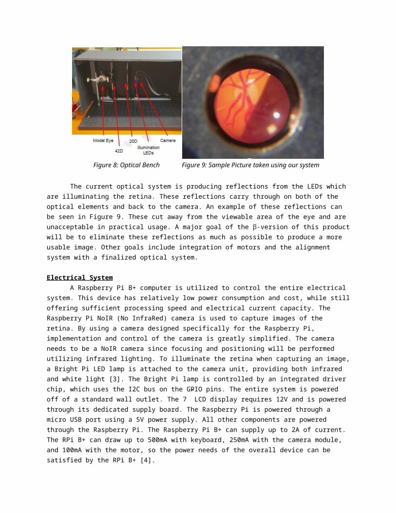
An image of our optical system is shown below in Figure 8. Starting from right to left, there is the camera (mounted on the right of the blue post), IR and white light LEDs (mounted on the left of the blue post), the 20 diopter lens, the 42 diopter lens, and the model eye. The inter-optical distances vary for focus on each image. Adjustments can be made by translating along the rail on linear bearings.
Figure 8: Optical Bench Figure 9: Sample Picture taken using our system
The current optical system is producing reflections from the LEDs which are illuminating the retina. These reflections carry through on both of the optical elements and back to the camera. An example of these reflections can be seen in Figure 9. These cut away from the viewable area of the eye and are unacceptable in practical usage. A major goal of the β-version of this product will be to eliminate these reflections as much as possible to produce a more usable image. Other goals include integration of motors and the alignment system with a finalized optical system.
Electrical System

A Raspberry Pi B+ computer is utilized to control the entire electrical system. This device has relatively low power consumption and cost, while still offering sufficient processing speed and electrical current capacity. The Raspberry Pi NoIR (No InfraRed) camera is used to capture images of the retina. By using a camera designed specifically for the Raspberry Pi, implementation and control of the camera is greatly simplified. The camera needs to be a NoIR camera since focusing and positioning will be performed utilizing infrared lighting. To illuminate the retina when capturing an image, a Bright Pi LED lamp is attached to the camera unit, providing both infrared and white light [3]. The Bright Pi lamp is controlled by an integrated driver chip, which uses the I2C bus on the GPIO pins. The entire system is powered off of a standard wall outlet. The 7” LCD display requires 12V and is powered through its dedicated supply board. The Raspberry Pi is powered through a micro USB port using a 5V power supply. All other components are powered through the Raspberry Pi. The Raspberry Pi B+ can supply up to 2A of current. The RPi B+ can draw up to 500mA with keyboard, 250mA with the camera module, and 100mA with the motor, so the power needs of the overall device can be satisfied by the RPi B+ [4].
Movement of the camera lens can be achieved through a stepper motor driven by the Raspberry Pi’s GPIO pins via a ULN2003 driver chip. The stepper motor was chosen for precision and ability to perform slow incremental motions which is vital for proper focusing and alignment of the camera. A resistive touch screen was purchased to overlay the 7” LCD display to allow for touch capability and connects via USB port on the Raspberry Pi.
Figure 10: Raspberry Pi B+ Figure 11: RPi Camera
Computer SystemThe Raspberry Pi (RPi) B+, with 700 Mhz ARM1176JZFS Applications Processor and 512MB
SDRAM(Figure 10), and the Raspberry Pi NoIR PiCamera (Figure 11) are used to handle all functionality of the fundus camera image capturing system. In addition, one of the 4 USB ports on the RPi are used for a wireless keyboard. The system also has touch screen capabilities that would utilize another USB port and internet connectivity through a hard wired direct connection. The entire computer system is tied together in an application written in the Python 3.2 programming language.
The application interfacing started off based strongly off of the capabilities of the PiCamera API (application program interface). This library of camera functionality suited the main needs for the fundus camera. From there, more advanced functionality was designed incorporating multiple methods of the camera’s API. With the addition of patient data storage and processing python class, the current terminal input-output application needed a graphical user interface (GUI).
The GUI of this application was designed using PyQt4, a set of Python modules used with Qt for GUI design and implementation. After completing a hand-draw GUI layout, the three main application frames were created and visualized using Qt Designer. This process was chosen over manually coding the GUI because the visualization and the drag-drop design allowed for simple GUI testing. Once the
initial format of the GUI was generated, an additional Python class using PyQt4 and the generated Qt Designer code was created to interface the application logic to the GUI design.
The fundus camera application will accept all pertinent patient information: name, date of birth, ID, and which eye is being captured (Figure 12). The app will then display a camera preview of what is being captured which is used for patient and camera alignment (Figure 13). A photo is then captured in 1280x720 resolution with a filename of ‘patientID_[R/L].jpeg’. A post capture display is then shown to the user with the ability to retake or take a picture of the next eye. The final fundus photographs are then saved in a shared folder that can be accessed over a local network connection with the correct password.
Figure 12:ClaRITy Software GUI Figure 13: Image Preview within GUI
Camera Housing SystemThe housing system is responsible for protecting and supporting the camera during use and
transportation. Because the project is proving a concept, the optical system is not complete. The camera housing is designed, but may require tuning after the optical system is completed. Thanks to collaboration with Linda Deng, an Industrial Design Student, and Brittany Bateman, a Biomedical Photography Student, we have decided on the following design.
Figure 14: Camera Housing System as drawn by Linda Deng Figure 15: Model and stand presented at Imagine RIT
2015
The main advantages of the system in Figure 14 are that it takes up less space than a typical fundus camera without sacrificing any stability. Handheld fundus cameras are the easiest to store and transport, but sacrifice stability and comfort for both the healthcare professional and the patient. This

design takes into account that the weight of the camera and the patient’s head will be directed between their feet. By placing the stand as close to the patient as possible, we use very little material while supporting the patient’s head and the camera. Existing systems support the weight of the camera on a table in front of the patient, therefore requiring more material and space. Luckily, our optical system is much simpler and lighter than existing systems, allowing us to fold the camera up and separate it from the base for easy transport and storage when not in use. For Imagine RIT 2015, because the camera housing could not be integrated with the incomplete optics, we have designed a model that will show how the system will appear and interact with patients (Figure 15).
The support system is a frame of 80/20 aluminum building material. It has been designed to support the weight of the camera, the patient's head, and the electronics, without buckling or moving. Because of the modular design of 80/20, the system can be easily taken apart and put back together quickly for storage in small areas. If it is to be used often, the frame can be fitted with wheels and moved by a single person with minimal effort. 80/20 can fabricate custom parts, so once the optics are finalized and the maximum weight of the complete housing unit is determined, custom wheels can be ordered and installed quite quickly. As the final housing unit is presently incomplete, the 80/20 system is slightly different from the original design. Instead of a telescoping camera support beam, there is a single support beam with a linear bearing and handbrake rated to 100 lbs to adjust the camera height. If the final optics system is too heavy, or the handbrake is unwieldy, a telescoping support beam may have to be integrated. The 80/20 was chosen because it can easily be integrated with other systems, so the next iteration of the project can take this model and improve it.
The only aspect of the camera that contacts the patient is a chinrest and forehead support. This system is identical to the facial support systems on existing fundus cameras. The contact points are easy to clean and completely FDA compliant.
Results and DiscussionThis team’s goal is proof of concept; to show that it is possible to produce a camera with cost and
design limitations. While we may not have completely met our goals pertaining to camera quality due to the field of view, we have produced a working camera, and the systems to support it. From here, we must consider the future of the project. We have known from the beginning this project would be continued as a β-project. The greatest thing we have learned is that the optical system is very exacting and complex. Our designed system does take quality images, but has a lower field of view than initially specified. The next iteration of this project should spend most of their time researching different ways to improve the optical system, and testing it extensively. With the inclusion of dedicated optical design team members, this area of the device could be more knowledgeably and completely designed.
Unfortunately, many of our systems are completely based on the optical design. The housing unit needs to be built around the optics. The support stand is ready, but should be tested with the final optics. The immediate casing unit has been designed, and a model is built, but the final design may need to be altered, if the camera itself is too large or unwieldy. We have confirmed that the electronics, such as the motors and power supply, and Raspberry Pi programming work with the existing system, but if optical complications arise, they will need to be re-examined.
Conclusions and RecommendationsThe goal of the project was to create a simpler and more inexpensive fundus camera. While we
have succeeded in that goal, there is still work to be done improving some of the qualities of the system. With improvements to the optical system, especially concerning field of view, this project would have incredible applications in detecting early diabetic retinopathy. The device is designed to be used in a general care practitioner’s office, so it is easier to use and more portable. The device is much less expensive, thanks to carefully chosen materials and parts. With improvements from the next MSD team

on this project, we are confident that this device will be able to help doctors diagnose diabetic retinopathy earlier and more reliably, allowing them to properly treat more of their patients.
References[1] "Fundus Photography Overview - Ophthalmic Photographers' Society." Fundus Photography
Overview - Ophthalmic Photographers' Society. Ophthalmic Photographer's Society, 2013. Web. 12 May 2015.
[2] "Retina." Wikipedia. Wikimedia Foundation, 2015. Web. 12 May 2015.[3] “Bright Pi- Bright White and IR Camera Light for Raspberry Pi.” Pi Supply, 2015. Web. 12 May
2015.[4] “Raspberry Pi 1 Model B+.” Raspberry Pi, 2015. Web. 12 May 2015.
“Raspberry Pi FAQs.” Raspberry Pi, 2015. Web. 12 May 2015.
Acknowledgements: