edic research proposal 1 high-precision depth estimation ... exam/pr15shahpaski... · edic research...
TRANSCRIPT

EDIC RESEARCH PROPOSAL 1
High-Precision Depth Estimation Using StructuredLight with Application to 2.5D Printing
Marjan ShahpaskiIVRL, I&C, EPFL
Abstract—3D sensing is gaining momentum with the increaseof computational power, and with the possibility to display andfabricate the results with high fidelity. In this report we focuson high precision depth estimation of 2.5D scenes. We intend toacquire depth through structured light methods, and we presentan overview of the common light coding techniques. We identifyindirect illumination along with dynamic scene content as themain sources of noise for precise structured light scanning.Accordingly, we present works that identify and address thecauses for each source of noise.
Index Terms—structured light, depth estimation, interreflec-tions, subsurface scattering, defocus, vibrations.
I. INTRODUCTION
THE advances in virtual reality display technology andthe emergence of 2.5D/3D printers renewed the research
interest in 3D acquisition of real world objects and scenes.Digitization for virtual reality applications is often concen-trated on capturing our immediate surroundings, on the scalefrom simple objects to complete buildings. These applicationsput the primary focus on acquisition speed and robustness
Proposal submitted to committee: November 20th, 2015;Candidacy exam date: November 27th, 2015; Candidacy examcommittee: Prof. Pascal Fua, Prof. Sabine Susstrunk, Dr RonanBoulic.
This research plan has been approved:
Date: ————————————
Doctoral candidate: ————————————(name and signature)
Thesis director: ————————————(name and signature)
Thesis co-director: ————————————(if applicable) (name and signature)
Doct. prog. director:————————————(B. Falsafi) (signature)
EDIC-ru/05.05.2009
to different types of illumination and scales, where the mea-surement precision is generally of secondary importance. Theinterest that virtual reality applications created can be seenthrough the large number of commercially available productsand prototypes, some of which include Microsoft Kinect, AsusXtion, Apple PrimeSense, Intel RealSense and Google Tango.
Depth estimation for fabrication, positions precision on thefirst place. This is mainly due to the possibility of very pre-cise fabrication. Recent 2.5D printers are capable of printingwith sub-10 µm precision. On the other hand, optical depthestimation methods for general scenes have still not matchedthis precision.
During this project we will work towards a depth estimationsystem that can provide an accuracy on the order of 10 µm.The system will be used for estimating the depth of 2.5Dscenes that undergo only rigid motion. We define 2.5D to bethe set of surfaces that have a limited height to a couple ofcentimeters, do not have overhanging structures and are notfreestanding 3D objects. A major application of this system isthe acquisition of precise surface profiles of master paintings,which will then be reproduced through 2.5D printing.
We will focus on depth estimation based on structured lightprojection. These methods provide non-contact means of depthestimation by using a calibrated camera-projector pair. Moststructured light scanning techniques assume scenarios thatinvolve opaque objects under direct illumination. However,these assumptions are often violated in real world scenes,where the measured objects are translucent and experiencesignificant amounts of indirect illumination. Furthermore, thescenes are not always static due to object movement andvibrations. Under these optical and mechanical noises manycoded structured light techniques fail to decode the patternscorrectly, which hinders high-precision reconstruction. Workhas already been undertaken in this direction. However, iteither does not provide resistance to optical noise [3], [7],or resistance to mechanical noise [2], [4], [5].
Indirect or global illumination is the set of effects that in-clude interreflections, subsurface scattering and defocus. Theseeffects alter the directly projected patterns. Interreflections areconsidered as long-range effects, since they generally appearas low-frequency waves across the captured scene. Subsurfacescattering and defocus, on the other hand, are considered asshort-range effects, as their effect is local and manifests in alocal low-pass filtering of the projected pattern.
Interreflections are mainly caused by concavities in themeasured objects’ shape, where the directly projected lightgets reflected from the object surface onto other portions of

EDIC RESEARCH PROPOSAL 2
the object. It is generally assumed to be a reflection withlow spatial frequency, however, smooth metallic or plasticsurfaces can produce high-frequency mirror reflections. Sub-surface scattering happens with translucent objects, wherethe light enters the object at one point, experiences multipleinternal reflections, and exits the object over a small areaaround the entry point. Subsurface scattering together withcamera/projector defocus act as low-pass filters upon theprojected patterns.
In addition to degrading the projected patterns, subsur-face scattering can introduce measurement bias. During thescanning of Michelangelo’s David [6], the authors measureda depth bias of approximately 40 µm for light at normalincidence for the Carrara Statuario marble. This happenedbecause the incident light from the laser beam got scatteredand formed a volume below the surface of the marble. Thiscreated a false light centroid that was detected by the camera,instead of the direct reflection from the object’s surface.They reported that this bias was not consistent across themarble surface, and that it increased with the increase of thelight incidence angle. Since this depth bias cannot be easilycharacterized, designing methods that completely avoid it aredesirable.
Scene dynamics are another major source of artifacts thatmainly affect the techniques that project multiple patternswhen encoding the measured scene. For example, when mea-suring a part of the human body (face, eye curvature, etc.)it is highly unlikely that the subject will stay still duringall the projections. Furthermore, when scanning a scene withhigh precision even the slightest vibrations can introducemeasurement noise [7].
This proposal is structured as follows. In Section II wereview the main categories of structured light coding. SectionIII explains the causes that make the structured light patternsfail in the presence of undesirable indirect illumination. It alsopresents patterns that, under certain assumptions, are resistantto these artifacts. Depth estimation in the presence of dynamicscene content is discussed in Section IV. Finally, in Section Vwe conclude this proposal with possible directions for futureresearch that would help us address the issues related tohigh-precision depth estimation in the presence of optical andmechanical noises.
II. STRUCTURED LIGHT PATTERNS FOR SURFACEPROFILOMETRY
Salvi et al. in [1] present a comprehensive overview andclassification of a large variety of coded structured light (CSL)techniques. The aim of CSL is to encode the position of eachpixel (or a region) in the projected pattern in a unique way,such that a correct correspondence can be established betweenthe projected and the captured patterns.
This field of research has been quite active in the past threedecades. A myriad of CSL techniques is now available, all of-fering different trade-offs that are suited for specific purposes.[1] cites more than forty CSL methods and classifies themhierarchically. Covering all different classes of algorithms indetail will require a long discussion. Therefore, in this section
Fig. 1. De Bruijn pattern with n = 4 and k = 3. Image taken from [1].
we will focus on the most general algorithms, and we will skiptheir variations developed for specific purposes. The coarsestlevel of classification divides the CSL patterns into discreteand continuous coding methods.
A. Discrete Coding Methods
Discrete coding methods are characterized by the discretenature of the projected pattern(s), i.e., the projected signalvaries in discrete and distinct steps across its dimensions. Ingeneral, they use an absolute coding strategy, as opposed toa relative coding strategy, meaning that each projected stripecan be uniquely identified.
The discrete coding techniques are further divided into spa-tial and time multiplexing. The spatial multiplexing patternsuse the surrounding of the features to encode their locationsin the pattern, while the time multiplexing patterns localizethe pixels by projecting multiple successive patterns, whereeach pattern provides a piece of the pixels’ unique codewords.Therefore, the spatial multiplexing techniques require only asingle projected pattern, and the time multiplexing techniquesrequire a series of projected patterns. The trade-off betweenprojecting single or multiple patterns is that although a singlepattern can be used for imaging moving targets, to achievethe same precision they need larger alphabet sizes, whichdecreases their noise resistance. Therefore the temporal multi-plexing techniques tend to achieve higher spatial accuracy anddensity.
De Bruijn sequence is the most commonly used patternamong the spatial multiplexing methods. A k-ary De Bruijnsequence of order n is a cyclic sequence, created from analphabet of size n, that contains each subsequence of length konly once. The length of the sequence is nk−1. This sequenceis interesting for structured light coding since by using a 1Dsliding window of size k along the epipolar lines, we canuniquely identify the position of each projected stripe in thecaptured image. An example De Bruijn sequence composedof n = 4 colors and window size of k = 3 stripes can be seenin Figure 1.
The measurement quality of these methods is directly linkedto the number of projected stripes or slits (the stripes areadjacent to each other, while the slits are stripes separatedby black gaps). The number of stripes that can be projectedis equal to the length of the De Bruijn sequence, which inturn depends on the codeword basis n and the length of thesubsequences k. If k increases, the algorithms have difficultiesestablishing the correspondences in areas where the patternis obscured by shadow. In addition, the algorithms are moresusceptible to noise, since the probability that at least oneof the stripes from the sliding window will be affected by

EDIC RESEARCH PROPOSAL 3
123456789
10
Fig. 2. 10 successive projections that encode the scene with Gray code. Theordinal number m = {1,...,10} is shown on the left side of each pattern.
noise increases. If, on the other hand, n increases, then theradiometric distance between the codewords decreases, whichincreases the chance of wrongly interpreting some codewords.Common approaches use 3-6 fully saturated and maximallydistant colors in the hue channel for the alphabet, and vary kin order to achieve the desired sequence length.
Among the first proposed strategies for structured lightcoding were the time multiplexing codes, that were introducedin 1982 by Posdamer and Altschuler [8]. The idea behindthe binary time multiplexing codes is simple: vertical binarystripes (usually black-white) are being projected subsequently,where in each successive projection the number of stripes dou-bles. The unique codewords are created after all the patternshave been projected. These projections usually follow a coarse-to-fine approach until the desired resolution is reached. Thenumber of addressable positions (in a single dimension) is 2m,where m is the number of projected patterns. The maximalachievable resolution is limited by the projector and/or thecamera used. Since the codeword basis in each projection issmall, this approach provides an increased resistance to noise,with the downside of not being able to capture moving scenes.
Gray code is the usual binary encoding of choice for timemultiplexing coding. Unlike the binary code, in Gray code theconsecutive codewords have a Hamming distance of one. Thismakes the encoding more resistant to noise, since it opens thepossibility for error correction. An example sequence of tenGray code projections can be seen in Figure 2.
The n-ary temporal codes go along the lines of the binarycodes; they only increase the size of the alphabet for each pro-jected pattern. Their alphabets commonly use colors, e.g. {red,green, blue}. The number of unique addressable positions inthe projected patterns can then be expressed by nm, where nis the alphabet size. This approach decreases the number ofprojections for achieving the same spatial resolution, however,it makes the patterns more prone to errors when the measuredsurface is colored.
B. Continuous Coding Methods
The continuous coding methods are characterized by acontinual variation of the coding intensities along the codingaxes. Grayscale patterns are the standard choice for thesemethods, which make them effective on object surfaces of anycolor. The methods in this group employ periodic encoding.
The phase shifting methods are a subclass of the continuouscoding methods. When projecting a periodic pattern on asurface, each point can be characterized by its phase offsetin the pattern. If there are non-flat objects in the scene, theywill cause a phase deviation in the pattern when compared to
the same pattern projected on a flat reference surface (plane).This deviation can be used to recover the height of surfacepoints relative to the reference plane. The projected signal canbe expressed as:
Ipn(xp, yp) = Ap +Bp cos(2πfΦxp − 2πn/N), (1)
where x is along the coding axis, the superscript p signifiesthe projected pattern, Ap and Bp are the signal offset and am-plitude, fΦ is the carrier frequency, (xp, yp) are the projectionpattern coordinates, and finally n = 0....N − 1. The patternthat the camera captures is the following:
In(x, y) = α(x, y)[Ac +Bc cos(2πfΦxp +φ(x, y)−2πn/N)]
(2)The captured pattern experiences both an intensity change
and a phase shift. The phase deviation is extracted as follows:
φ(x, y) = arctan
[∑Nn=1 In(x, y)sin(2πn/N)∑Nn=1 In(x, y)cos(2πn/N)
](3)
The retrieved phases are independent of the surface albedo.The minimal number of captured shifted patterns is N = 3,since there are three unknowns in the system: Ac, Bc andφ(x, y) [9]. Higher carrier frequencies yield higher signal-to-noise ratio, but are also more sensitive to sharp object edges.
With this computation we only recover the wrapped phaseof the surface points. It is called wrapped since the arctanfunction wraps the values in the range (−π, π]. Therefore aphase unwrapping algorithm has to be used to recover thenatural phases of the pixels. A simple approach to phaseunwrapping would be summing the gradients of the wrappedphases along a continuous path, starting from a reference pointand going to all other surface points. This approach assumesthat the absolute values of the gradient are always less thanπ, and if there is a π to −π discontinuity, it adds 2π (or viceversa). The height of a surface point relative to the referenceplane is then calculated as follows:
h(x, y) = l0φ− φr
φ− φr − 2πfΦd, (4)
where φ and φr are the unwrapped phases imaged at the samepixel location (x, y) for the measured surface and the referenceplane, respectively, l0 is the distance from the projector andcamera lenses to the reference plane, and d is the baselinedistance between the projector and camera lenses.
An obvious drawback of this method is the necessity toproject multiple patterns. Frequency multiplexing is anotherlarge subclass of continuous coding techniques. The differencewith the phase shifting methods is that they perform the phasedecoding in the frequency domain. They have an advantageover the phase shifting techniques because they require asingle projection to extract the height, thus they can deal withdynamic scenes. We will have an in-depth analysis of thismethod in section IV, as it is the method of choice in [3].

EDIC RESEARCH PROPOSAL 4
Fig. 3. The measured object has a concave edge in the middle. Top figure: ascene point marked with a red dot is directly lit when the positive pattern isprojected, and not directly lit when the inverse pattern is projected. However,it receives more light in the latter case, which leads to incorrect binarization.Bottom figure: the same scene is lit with a high frequency pattern, and thesame point as above is correctly binarized. Image taken from [2].
III. 3D SCANNING IN THE PRESENCE OF INDIRECTILLUMINATION
In this section, we review the work proposed by Gupta etal. [2]. This work focuses on the design of CSL patterns thatcan be used in real world scenarios. Real world scenariosimply pattern decoding in the presence of indirect illumination(interreflections, subsurface scattering and defocus), being theopposite of well behaved scenes, where the scene is lit onlyby direct illumination and the objects are opaque.
Their work is based on the binary time multiplexing codingstrategy that we have explained in subsection II-A. In thefollowing we will use the notion of low- and high-frequencypatterns to denote patterns that are composed of wide andnarrow stripes, respectively.
For detecting the projected stripes in the captured images,the images have to be binarized. A robust way for binarizationis by projecting a pattern P and an inverse pattern P , andcapturing images I and I of the two patterns respectively.By comparing the intensity of a given pixel si in I and thecorresponding pixel si in I , it can be determined if si belongsto an illuminated stripe if si > si.
To better understand their proposed approach, we have tostart with an analysis of the errors that are due to indirectillumination. They affect the pattern binarization process ofthe captured images, which subsequently yields erroneouscorrespondences between the projected and the captured pat-terns. Ultimately, this results in measurement errors in thetriangulation step.
The basic assumption for correct binarization is that eachscene point receives only direct illumination from a singleprojector pixel. Due to interreflections, a scene point mightalso receive illumination indirectly as reflected light from otherscene points. When the scene is illuminated by low-frequencypatterns, for objects with concavities it might happen that somepoints, that are part of an illuminated region, receive less light
Fig. 4. Structured light binarization in the presence of subsurface scattering.The scene (a) is composed of a translucent marble slab on the left side, andan opaque plane on the right side. It can be seen that (b) the high frequencypatterns are completely smoothed by the translucent background, and (c) theirbinarization fails. This does not happen with (d) the low-frequency patterns,and (e) their binarization is correct. Image taken from [2].
when they are directly lit by the positive pattern, and morelight when they are indirectly lit by the inverse pattern (Figure3, top). This results in wrong binarization, and it happensbecause the low-frequency patterns illuminate the scene highlyasymmetrically. According to [10], when projecting high-frequency patterns, scene points receive approximately equalamount of indirect illumination both when they are directlyilluminated or not, which leads to a correct binarization(Figure 3, bottom). Interreflections are also called long-rangeeffects, since they are effective over longer distances.
On the other hand, short-range effects such as subsurfacescattering and defocus, perform low-pass filtering on the pro-jected pattern. This happens because the short-range indirectillumination at a scene point comes from that point’s localneighborhood. Consequently, short-range effects can severelydegrade the edge definition of high-frequency patterns, ef-fectively turning the square waves into sine waves, or evencompletely blurring them out. An example of this effect isshown in Figure 4. Low-frequency patterns can therefore beused to counter this smoothing effect, as neighboring scenepoints are expected to be equally illuminated.
Most currently used time multiplexing binary coding tech-niques project a combination of both low- and high-frequencypatterns, e.g. Gray coding. Faced with the opposing require-ments for correct binarization, i.e., high-frequency codes forlong-range effects and low-frequency codes for short-rangeeffects, Gupta et al. [2] propose methods for generating codesconsisting of purely low- or high-frequency patterns, andcombining them into code ensembles when scanning an object.
Using the favorable properties of the XOR operator, theygenerate a logical code composed of only high-frequencies.The code is based on the Gray code. They select a base patternthat has a high-frequency and perform XOR between it andeach Gray code pattern that has a lower frequency than thebase pattern. The patterns that have a higher frequency thanthe base pattern are projected unmodified. This assures thatthe maximal stripe width of the resulting logical code is thestripe width of the base pattern. It also maintains the samenumber of patterns as in the original Gray code.
When the patterns are captured, they are first binarized,and then the XOR operation is performed again in the samefashion as when creating them. Due to the distributive andassociative properties of XOR, this process renders a binarizedversion of the conventional Gray code. These logical codes areresistant to interreflections, since they involve projecting only

EDIC RESEARCH PROPOSAL 5
high-frequency patterns. The authors name them according tothe base pattern used, i.e., XOR-2k+1, where k is the ordinalnumber of the base pattern in the Gray code when countingfrom the highest-frequency pattern. The number 2k+1 alsosignifies the maximal stripe width for the specific code.
Decreasing the pattern frequencies for combating short-range effects is equivalent to maximizing the minimal stripewidth of the projected patterns. For addressing this problem theauthors turn to combinatorial mathematics, more specifically,to the code proposed by Goddyn et al. [11]. Namely, the 10-bitversion of this modified Gray code has a minimum stripe widthof 8 pixels, compared to 2 pixels for the conventional Graycode. Gupta et al. name this code maximum min-SW (StripeWidth) Gray code. In addition, it has a maximal stripe widthof 32 pixels, which also makes it more suitable for long-rangeeffects compared to the conventional Gray code (max-SW of512 pixels).
Indirect illumination in real world scenes is usually notlimited to just long-range or short-range effects. Therefore, formeasuring general scenes the authors create an ensemble ofthe previous codes. Namely, they project two types of long-range codes (XOR-2 and XOR-4), and two types of short-range codes (maximum min-SW Gray code and conventionalGray code). The total number of projected patterns is 42, 10patterns for each code type (no inverse patterns), plus a fullyilluminated frame and a dark frame with the projector turnedoff, which are used to set a per-pixel intensity threshold forbinarization.
The final depth map is created by checking the consistencyof the four depth maps computed by each distinct encoding.The consistency check is based on the assumption that theerrors made by the different codes are nearly random. There-fore, if at least two depth values for a given pixel are withina threshold, the depth value is returned.
The consistency check is also used for error detection.Namely, if all four code types return a different depth valuefor a pixel, it is marked as an error pixel, irrelevant of the factthat one of the codes might return a correct depth value.
An error correction step is then performed by reprojectingthe coded patterns only for the error pixels (masking out thecorrectly measured pixels). This approach helps in loweringthe indirect illumination that the erroneous pixels might re-ceive from other pixels in the scene. The authors report that anearly complete reconstruction can be achieved after only 1-2 error correcting iterations, since the initial projection of theerror preventing codes correctly reconstructs a large fraction ofthe scene. They report an accuracy of 1.2 mm for a challengingscene containing a brushed metal bowl.
The presented method classifies the indirect illuminationinto short- and long-range. The low-frequency patterns expectthe subsurface scattering to be local, and the high-frequencypatterns assume that the interreflections are locally smooth(no mirror interreflections). If any of these two assumptionsis violated, the reconstruction will fail.
Another limitation of the approach is that it can be appliedonly to scenes where the points receive a single dominanttype of indirect illumination. None of the proposed codingstrategies is suited for handling both classes of indirect illu-
d
ℓ0
O-h
I
P E
R
G
S
B CD
H
A
Object
P∞
Projector Camera
Reference plane
x
yz
Fig. 5. Typical crossed-optical-axes setup for Fourier transform profilometry.
minations, since they have opposing requirements: long-rangeeffects require high-frequency patterns, and the short-rangeeffects require low-frequency patterns.
Finally, the algorithm requires the projection of several tensof images. This decreases the acquisition speed of the systemand makes it unsuitable for dynamic scenarios.
IV. DYNAMIC 3D SHAPE MEASUREMENT METHOD
In this section we will review the method proposed bySu and Zhang [3] that is suitable for shape measurement ofdynamic objects. Their method is based on Fourier transformprofilometry (FTP) introduced by Takeda and Mutoh [12].
On Figure 5 we can observe the typical setup for FTP. PointsP and E are the positions of the projector and the cameralenses, respectively. They are both positioned at a distancel0 from a reference plane R, and the distance between themis d. R is perpendicular to the ray passing through points Eand O, and it is the plane that the camera captures. We willconsider this plane as the reference plane from which we willexpress the relative height measurements, i.e., the plane forwhich h(x, y) = 0.
As we briefly explained in subsection II-B, the projectorprojects a sinusoidal pattern that lies undistorted on planeI . If point P is at infinity (P∞ on Figure 5), an exampleprojected ray would intersect plane R at point B. Moreover,the projected pattern will appear undistorted on plane R.However, since in reality point P is at a finite distancefrom R, the same projected ray will intersect plane R atpoint C. The distance BC is the distortion of the projectedsinusoidal pattern that the camera will capture. We can alsoexpress this distortion as a phase shift of the captured pattern:φ0(x) = 2πf0BC. We can express the captured signal moreformally by using the Fourier series representation:
g0(x, y) = r0(x, y)
∞∑n=−∞
An exp(i[2πnf0x+ nφ0(x)]) (5)
where f0 is the fundamental frequency of the captured signaland r0(x, y) is the spatially varying surface reflectivity of the
EDIC RESEARCH PROPOSAL 6
f0 2f0 3f00
|G(f, y)|
(Q1)min (Q1)max(Qb)max (Q2)min (Q3)min (Q2)max
Q1
Q2 Q3
(Q3)max
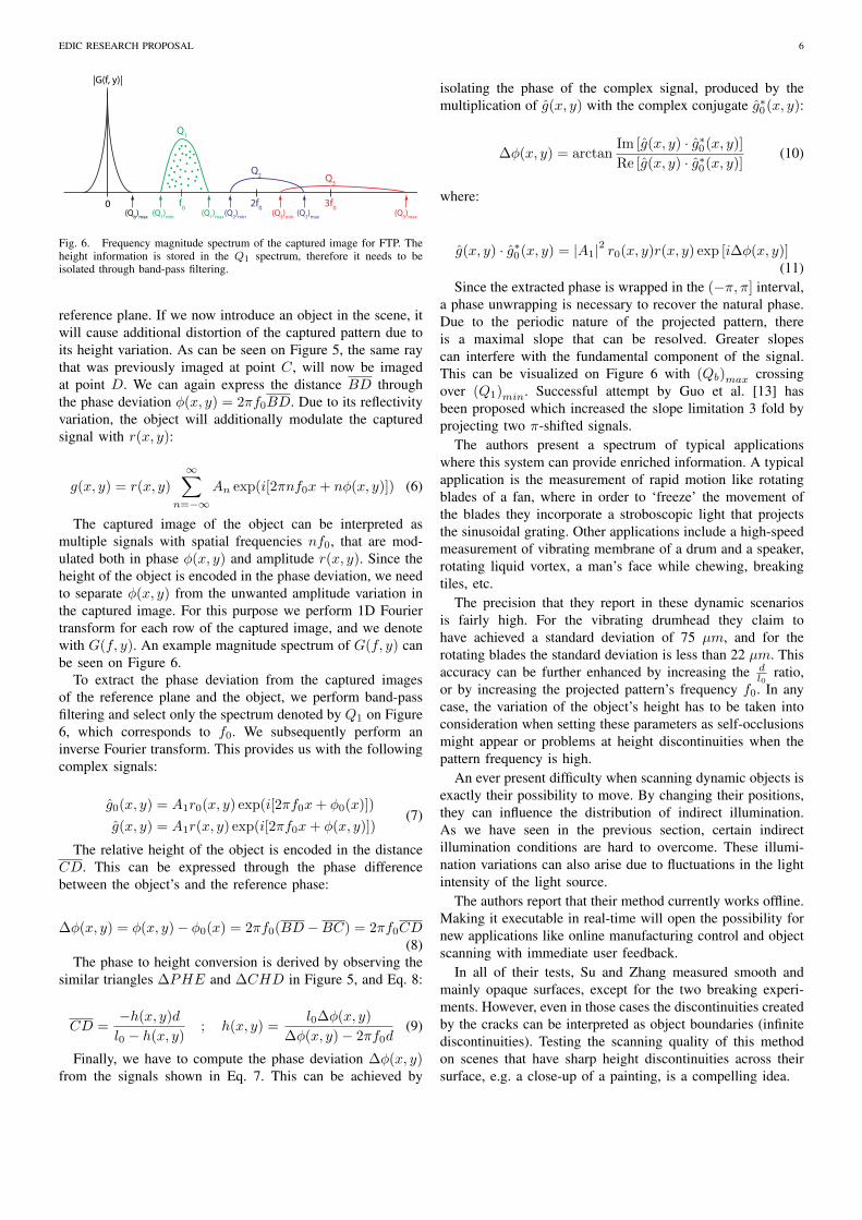
Fig. 6. Frequency magnitude spectrum of the captured image for FTP. Theheight information is stored in the Q1 spectrum, therefore it needs to beisolated through band-pass filtering.
reference plane. If we now introduce an object in the scene, itwill cause additional distortion of the captured pattern due toits height variation. As can be seen on Figure 5, the same raythat was previously imaged at point C, will now be imagedat point D. We can again express the distance BD throughthe phase deviation φ(x, y) = 2πf0BD. Due to its reflectivityvariation, the object will additionally modulate the capturedsignal with r(x, y):
g(x, y) = r(x, y)
∞∑n=−∞
An exp(i[2πnf0x+ nφ(x, y)]) (6)
The captured image of the object can be interpreted asmultiple signals with spatial frequencies nf0, that are mod-ulated both in phase φ(x, y) and amplitude r(x, y). Since theheight of the object is encoded in the phase deviation, we needto separate φ(x, y) from the unwanted amplitude variation inthe captured image. For this purpose we perform 1D Fouriertransform for each row of the captured image, and we denotewith G(f, y). An example magnitude spectrum of G(f, y) canbe seen on Figure 6.
To extract the phase deviation from the captured imagesof the reference plane and the object, we perform band-passfiltering and select only the spectrum denoted by Q1 on Figure6, which corresponds to f0. We subsequently perform aninverse Fourier transform. This provides us with the followingcomplex signals:
g0(x, y) = A1r0(x, y) exp(i[2πf0x+ φ0(x)])
g(x, y) = A1r(x, y) exp(i[2πf0x+ φ(x, y)])(7)
The relative height of the object is encoded in the distanceCD. This can be expressed through the phase differencebetween the object’s and the reference phase:
∆φ(x, y) = φ(x, y)− φ0(x) = 2πf0(BD−BC) = 2πf0CD(8)
The phase to height conversion is derived by observing thesimilar triangles ∆PHE and ∆CHD in Figure 5, and Eq. 8:
CD =−h(x, y)d
l0 − h(x, y); h(x, y) =
l0∆φ(x, y)
∆φ(x, y)− 2πf0d(9)
Finally, we have to compute the phase deviation ∆φ(x, y)from the signals shown in Eq. 7. This can be achieved by
isolating the phase of the complex signal, produced by themultiplication of g(x, y) with the complex conjugate g∗0(x, y):
∆φ(x, y) = arctanIm [g(x, y) · g∗0(x, y)]
Re [g(x, y) · g∗0(x, y)](10)
where:
g(x, y) · g∗0(x, y) = |A1|2 r0(x, y)r(x, y) exp [i∆φ(x, y)](11)
Since the extracted phase is wrapped in the (−π, π] interval,a phase unwrapping is necessary to recover the natural phase.Due to the periodic nature of the projected pattern, thereis a maximal slope that can be resolved. Greater slopescan interfere with the fundamental component of the signal.This can be visualized on Figure 6 with (Qb)max crossingover (Q1)min. Successful attempt by Guo et al. [13] hasbeen proposed which increased the slope limitation 3 fold byprojecting two π-shifted signals.
The authors present a spectrum of typical applicationswhere this system can provide enriched information. A typicalapplication is the measurement of rapid motion like rotatingblades of a fan, where in order to ‘freeze’ the movement ofthe blades they incorporate a stroboscopic light that projectsthe sinusoidal grating. Other applications include a high-speedmeasurement of vibrating membrane of a drum and a speaker,rotating liquid vortex, a man’s face while chewing, breakingtiles, etc.
The precision that they report in these dynamic scenariosis fairly high. For the vibrating drumhead they claim tohave achieved a standard deviation of 75 µm, and for therotating blades the standard deviation is less than 22 µm. Thisaccuracy can be further enhanced by increasing the d
l0ratio,
or by increasing the projected pattern’s frequency f0. In anycase, the variation of the object’s height has to be taken intoconsideration when setting these parameters as self-occlusionsmight appear or problems at height discontinuities when thepattern frequency is high.
An ever present difficulty when scanning dynamic objects isexactly their possibility to move. By changing their positions,they can influence the distribution of indirect illumination.As we have seen in the previous section, certain indirectillumination conditions are hard to overcome. These illumi-nation variations can also arise due to fluctuations in the lightintensity of the light source.
The authors report that their method currently works offline.Making it executable in real-time will open the possibility fornew applications like online manufacturing control and objectscanning with immediate user feedback.
In all of their tests, Su and Zhang measured smooth andmainly opaque surfaces, except for the two breaking experi-ments. However, even in those cases the discontinuities createdby the cracks can be interpreted as object boundaries (infinitediscontinuities). Testing the scanning quality of this methodon scenes that have sharp height discontinuities across theirsurface, e.g. a close-up of a painting, is a compelling idea.

EDIC RESEARCH PROPOSAL 7
V. RESEARCH PROPOSAL
The methods that provide resilience to optical noise ([2],[4], [5]) do not provide quantitative precision values. Guptaet al. [2] do not report their method’s precision in relationto a ground-truth object height, but only qualitatively andapproximately in relation to a manual binarization of theprojected stripes. Su et al. [3] report only the standard de-viation (repeatability) of their measurements. However, bias isto be expected due to subsurface scattering in both cases [6].Therefore, we would like to study their precision by measuringobjects that have known surface profiles and that exhibitoptical noise, have varying slopes and depth discontinuities.For this purpose, we can fabricate precise objects that havethe desired surface characteristics by using a 2.5D printer. Inaddition, contact profilometer can be used for obtaining thesurface height of objects made from any material.
Polarization has proved to be an effective method foravoiding indirect illumination, as shown in [14]. Namely, lightreflected from the surface of a dielectric (insulating) materialis partially polarized. If it undergoes multiple reflections (dueto interreflections or subsurface scattering), it gets randomlypolarized. Therefore, if the projected light is polarized and thecamera also has a polarization filter with the same orientation,it will partially discard the indirect component. Although thismethod does not completely remove the indirect illuminationcomponent, it increases the signal intensity that arrives fromthe direct component. Thus it represents a tool for increasingthe measurement precision.
From previous experiments we have observed that lightwhich has a shorter wavelength does not penetrate the objects’surface as deeply as does light with a longer wavelength. Theusage of blue or ultraviolet light represents another directionfor investigation, in spite of ultraviolet light’s power beingrestricted for many materials.
From [2] we have learned that high-frequency patternsare required in the presence of interreflections, and thatsubsurface scattering and defocus smooth the input signal.A sinusoidal signal, as used in [3], can have an arbitrarilylarge frequency (limited by the projector resolution) for copingwith interreflections. In addition, when a sinusoidal signal issmoothed by short-range effects its amplitude decreases, but itsfrequency does not change, lowering its signal-to-noise ratio.With the choice of the right frequency, we expect FTP to behighly resilient to optical noise. An open problem that we willhave to address is the choice of the projected frequency, whichdepends on the resolution of the projector and the camera, theirnoise levels, and on the light transport characteristics of thescene.
Our initial tests with binary time multiplexing patterns haveconfirmed the problems of pattern binarization in the presenceof interreflections, when using a conventional CSL encoding(e.g. Gray code). Another issue that we have encountered isthe separation of the red, green and blue projected channels,when projecting a grayscale pattern, on surfaces with largerslopes. This problem limits the methods that depend on theprojection of multiple distinct patterns to smaller slopes or toa more specialized equipment. The FTP method, on the other
hand, uses a single pattern that can be printed and attached toa point light source for projection.
The FTP method is also suitable for scenarios that involvevibrations, since it estimates depth from a single frame.Furthermore, having vibrations might even be useful for im-proving the measured depth. The KinectFusion algorithm [15]fuses multiple similar observations of a scene in order to de-crease the noise that is present in the individual observations.Consequently, it also renders a more detailed scene. We wouldtherefore like to explore if this algorithm is applicable to ourscenario. Since they use a fixed discretization of the capturedspace, we already expect to run into problems with limitedworking volumes or very large memory consumption.
As a long term goal, we would like to make high-precision3D scanning applicable to a large class of complex, real worldscenarios, alleviating the need for specialized and expensiveequipment. Our main interest is in preservation, restoration,visualization and physical reproduction of cultural heritageobjects. We also imagine this technology to be used foracquiring precise models of the human body, or for providingprecise guidance to surgical instruments inside the body whileoperating.
REFERENCES
[1] J. Salvi, S. Fernandez, T. Pribanic, and X. Llado, ”A state of the artin structured light patterns for surface profilometry.” Pattern recognition43.8 (2010): 2666-2680.
[2] M. Gupta, A. Agrawal, A. Veeraraghavan, and S. G. Narasimhan, ”Apractical approach to 3D scanning in the presence of interreflections,subsurface scattering and defocus.” International journal of computervision 102.1-3 (2013): 33-55.
[3] X. Su, and Q. Zhang, ”Dynamic 3-D shape measurement method: areview.” Optics and Lasers in Engineering 48.2 (2010): 191-204.
[4] M. Gupta, and S.K. Nayar, ”Micro phase shifting.” Computer Vision andPattern Recognition, 2012. IEEE Conference on. (pp. 813-820).
[5] T. Chen, H. P. Seidel, and H. Lensch, ”Modulated phase-shifting for3D scanning.” Computer Vision and Pattern Recognition, 2008. IEEEConference on. (pp. 1-8).
[6] M. Levoy, et al., ”The digital Michelangelo project: 3D scanning oflarge statues.” Proceedings of the 27th annual conference on Computergraphics and interactive techniques., (2000).
[7] F. Blais, M. Picard, and G. Godin, ”Accurate 3D acquisition of freelymoving objects.” Proceedings of the 2nd International Symposium on 3DData Processing, Visualization and Transmission, 2004. (pp. 422-429).
[8] J. L. Posdamer, and M. D. Altschuler, ”Surface measurement by space-encoded projected beam systems.” Computer graphics and image pro-cessing 18.1 (1982): 1-17.
[9] B. Bhushan, J. C. Wyant, and C. L. Koliopoulos, ”Measurement of surfacetopography of magnetic tapes by Mirau interferometry.” Applied Optics24.10 (1985): 1489-1497.
[10] S. K. Nayar, G. Krishnan, M. D. Grossberg, and R. Raskar, ”Fastseparation of direct and global components of a scene using highfrequency illumination.” ACM Transactions on Graphics 25.3 (2006):935-944.
[11] L. Goddyn, and P. Gvozdjak, ”Binary gray codes with long bit runs.”The electronic journal of combinatorics 10.1 (2003): R27.
[12] M. Takeda, and K. Mutoh, ”Fourier transform profilometry for theautomatic measurement of 3-D object shapes.” Applied optics 22.24(1983): 3977-3982.
[13] L. Guo, X. Su, and J. Li, ”Improved Fourier transform profilometry forthe automatic measurement of 3D object shapes.” Optical Engineering29.12 (1990): 1439-1444.
[14] T. Chen, H. Lensch, C. Fuchs, and H. P. Seidel, ”Polarization and phase-shifting for 3D scanning of translucent objects.” Computer Vision andPattern Recognition, 2007. IEEE Conference on. (pp. 1-8).
[15] Newcombe, Richard A., et al., ”KinectFusion: Real-time dense surfacemapping and tracking.” Mixed and augmented reality (ISMAR), 2011 10thIEEE international symposium on. 2011.