edition 1.0 2015-06 international standardiec+1776… · edition 1.0 2015-06 iso/iec 17760-101...
TRANSCRIPT

Edition 1.0 2015-06
ISO/IEC 17760-101
INTERNATIONAL STANDARD
Information technology – AT attachment 8 – Part 101: ATA/ATAPI Command Set (ACS)
ISO
/IEC
177
60-1
01:2
015-
06(e
n)
colourinside
This is a preview of "ISO/IEC 17760-101:20...". Click here to purchase the full version from the ANSI store.This is a preview of "ISO/IEC 17760-101:20...". Click here to purchase the full version from the ANSI store.This is a preview of "ISO/IEC 17760-101:20...". Click here to purchase the full version from the ANSI store.This is a preview of "ISO/IEC 17760-101:20...". Click here to purchase the full version from the ANSI store.
THIS PUBLICATION IS COPYRIGHT PROTECTED Copyright © 2015 ISO/IEC, Geneva, Switzerland All rights reserved. Unless otherwise specified, no part of this publication may be reproduced or utilized in any form or by any means, electronic or mechanical, including photocopying and microfilm, without permission in writing from either IEC or IEC's member National Committee in the country of the requester. If you have any questions about ISO/IEC copyright or have an enquiry about obtaining additional rights to this publication, please contact the address below or your local IEC member National Committee for further information. IEC Central Office Tel.: +41 22 919 02 11 3, rue de Varembé Fax: +41 22 919 03 00 CH-1211 Geneva 20 [email protected] Switzerland www.iec.ch
About the IEC The International Electrotechnical Commission (IEC) is the leading global organization that prepares and publishes International Standards for all electrical, electronic and related technologies. About IEC publications The technical content of IEC publications is kept under constant review by the IEC. Please make sure that you have the latest edition, a corrigenda or an amendment might have been published. IEC Catalogue - webstore.iec.ch/catalogue The stand-alone application for consulting the entire bibliographical information on IEC International Standards, Technical Specifications, Technical Reports and other documents. Available for PC, Mac OS, Android Tablets and iPad. IEC publications search - www.iec.ch/searchpub The advanced search enables to find IEC publications by a variety of criteria (reference number, text, technical committee,…). It also gives information on projects, replaced and withdrawn publications. IEC Just Published - webstore.iec.ch/justpublished Stay up to date on all new IEC publications. Just Published details all new publications released. Available online and also once a month by email.
Electropedia - www.electropedia.org The world's leading online dictionary of electronic and electrical terms containing more than 30 000 terms and definitions in English and French, with equivalent terms in 15 additional languages. Also known as the International Electrotechnical Vocabulary (IEV) online. IEC Glossary - std.iec.ch/glossary More than 60 000 electrotechnical terminology entries in English and French extracted from the Terms and Definitions clause of IEC publications issued since 2002. Some entries have been collected from earlier publications of IEC TC 37, 77, 86 and CISPR. IEC Customer Service Centre - webstore.iec.ch/csc If you wish to give us your feedback on this publication or need further assistance, please contact the Customer Service Centre: [email protected].
This is a preview of "ISO/IEC 17760-101:20...". Click here to purchase the full version from the ANSI store.This is a preview of "ISO/IEC 17760-101:20...". Click here to purchase the full version from the ANSI store.This is a preview of "ISO/IEC 17760-101:20...". Click here to purchase the full version from the ANSI store.This is a preview of "ISO/IEC 17760-101:20...". Click here to purchase the full version from the ANSI store.

ISO/IEC 17760-101 Edition 1.0 2015-06
INTERNATIONAL STANDARD
Information technology – AT attachment 8 – Part 101: ATA/ATAPI Command Set (ACS)
INTERNATIONAL ELECTROTECHNICAL COMMISSION
ICS 35.200
ISBN 978-2-8322-2695-7
Warning! Make sure that you obtained this publication from an authorized distributor.
colourinside
This is a preview of "ISO/IEC 17760-101:20...". Click here to purchase the full version from the ANSI store.This is a preview of "ISO/IEC 17760-101:20...". Click here to purchase the full version from the ANSI store.This is a preview of "ISO/IEC 17760-101:20...". Click here to purchase the full version from the ANSI store.This is a preview of "ISO/IEC 17760-101:20...". Click here to purchase the full version from the ANSI store.
– 2 – ISO/IEC 17760-101:2015 © ISO/IEC 2015
CONTENTS
FOREWORD....................................................................................................................................... 14
INTRODUCTION .......................................................................................................................16
1 Scope ....................................................................................................................................17
2 Normative references ............................................................................................................17
3 Terms, definitions and conventions ........................................................................................183.1 Terms and definitions .....................................................................................................183.2 Conventions ....................................................................................................................25
3.2.1 Overview ...............................................................................................................253.2.2 Precedence ...........................................................................................................253.2.3 Lists ......................................................................................................................263.2.4 Keywords ..............................................................................................................263.2.5 Numbering ............................................................................................................273.2.6 Bit conventions ......................................................................................................283.2.7 State diagram conventions ....................................................................................283.2.8 Byte, word, DWord, and QWord Relationships ......................................................293.2.9 ATA string convention ...........................................................................................31
4 Feature set definitions ...........................................................................................................324.1 Overview ........................................................................................................................324.2 General feature set .........................................................................................................324.3 The PACKET feature set .................................................................................................33
4.3.1 Overview ...............................................................................................................334.3.2 Identification of PACKET feature set devices ........................................................344.3.3 Signature for ATAPI devices .................................................................................344.3.4 The PACKET command ........................................................................................34
4.4 48-bit Address feature set ...............................................................................................344.5 Advanced Power Management (APM) feature set ...........................................................354.6 Automatic Acoustic Management (AAM) feature set ........................................................354.7 CompactFlash Association (CFA) feature set ..................................................................354.8 Device Configuration Overlay (DCO) feature set .............................................................364.9 Free-fall Control feature set ............................................................................................384.10 General Purpose Logging (GPL) feature set .................................................................384.11 Host Protected Area (HPA) feature set .........................................................................39
4.11.1 HPA overview ......................................................................................................394.11.2 HPA security extensions ......................................................................................394.11.3 28-bit and 48-bit HPA commands interactions .....................................................394.11.4 IDENTIFY DEVICE data ......................................................................................414.11.5 Determination of SET MAX security extension status ..........................................414.11.6 HPA State Transition Diagrams ...........................................................................41
4.12 Long Logical Sector (LLS) feature set ...........................................................................564.13 Long Physical Sector (LPS) feature set .........................................................................584.14 Media Card Pass Through Command feature set ..........................................................604.15 Native Command Queuing (NCQ) feature set ...............................................................60
4.15.1 Overview .............................................................................................................604.15.2 Command Phases ...............................................................................................61
This is a preview of "ISO/IEC 17760-101:20...". Click here to purchase the full version from the ANSI store.This is a preview of "ISO/IEC 17760-101:20...". Click here to purchase the full version from the ANSI store.This is a preview of "ISO/IEC 17760-101:20...". Click here to purchase the full version from the ANSI store.This is a preview of "ISO/IEC 17760-101:20...". Click here to purchase the full version from the ANSI store.
ISO/IEC 17760-101:2015 © ISO/IEC 2015 – 3 –
4.16 NV Cache feature set ....................................................................................................614.16.1 Overview .............................................................................................................614.16.2 Pinning ................................................................................................................614.16.3 NV Cache Management ......................................................................................624.16.4 Rotating media state after power-on event ..........................................................62
4.17 NV Cache Power Management feature set ...................................................................624.18 Power Management feature set ....................................................................................63
4.18.1 Overview .............................................................................................................634.18.2 Power management commands ..........................................................................634.18.3 Standby timer ......................................................................................................644.18.4 Power modes ......................................................................................................64
4.19 Power-Up In Standby (PUIS) feature set .......................................................................664.20 Security feature set .......................................................................................................66
4.20.1 Overview .............................................................................................................664.20.2 Passwords ..........................................................................................................674.20.3 Master Password Capability ................................................................................674.20.4 Frozen Mode .......................................................................................................674.20.5 Commands ..........................................................................................................674.20.6 IDENTIFY DEVICE data ......................................................................................674.20.7 Security initial setting ..........................................................................................684.20.8 Password rules ....................................................................................................684.20.9 Password attempt counter ...................................................................................684.20.10 Security states ..................................................................................................694.20.11 Master Password Identifier feature ....................................................................78
4.21 Self-Monitoring, Analysis, and Reporting Technology (SMART) feature set ..................794.21.1 Overview .............................................................................................................794.21.2 Device SMART data structure .............................................................................794.21.3 Background data collection .................................................................................794.21.4 Off-line/Captive mode data collection ..................................................................794.21.5 Threshold exceeded condition .............................................................................794.21.6 SMART feature set commands ............................................................................794.21.7 SMART operation with power management modes .............................................794.21.8 SMART device error log reporting .......................................................................80
4.22 Software Settings Preservation (SSP) feature set .........................................................804.23 Streaming feature set ....................................................................................................81
4.23.1 Streaming feature set overview ...........................................................................814.23.2 Streaming commands ..........................................................................................81
4.24 Tagged Command Queuing (TCQ) feature set ..............................................................824.24.1 Overview .............................................................................................................824.24.2 Queueing ............................................................................................................83
4.25 Trusted Computing feature set ......................................................................................834.26 Write-Read-Verify feature set ........................................................................................84
5 ATA protocols ........................................................................................................................86
6 Normal and Error Output field descriptions ............................................................................876.1 Overview ........................................................................................................................876.2 Status field ......................................................................................................................87
6.2.1 Overview ...............................................................................................................876.2.2 Busy bit .................................................................................................................876.2.3 Check Condition bit ...............................................................................................87
This is a preview of "ISO/IEC 17760-101:20...". Click here to purchase the full version from the ANSI store.This is a preview of "ISO/IEC 17760-101:20...". Click here to purchase the full version from the ANSI store.This is a preview of "ISO/IEC 17760-101:20...". Click here to purchase the full version from the ANSI store.This is a preview of "ISO/IEC 17760-101:20...". Click here to purchase the full version from the ANSI store.

– 4 – ISO/IEC 17760-101:2015 © ISO/IEC 2015
6.2.4 Data Request bit ...................................................................................................876.2.5 Deferred Write Error bit .........................................................................................876.2.6 Device Fault bit .....................................................................................................886.2.7 Device Ready bit ...................................................................................................886.2.8 Error bit .................................................................................................................886.2.9 Service bit .............................................................................................................886.2.10 Stream Error bit ...................................................................................................886.2.11 Transport Dependent (TD) ..................................................................................88
6.3 Error field ........................................................................................................................896.3.1 Overview ...............................................................................................................896.3.2 Abort bit ................................................................................................................896.3.3 Attempted Partial Range Removal bit ....................................................................896.3.4 Command Completion Time Out bit .......................................................................896.3.5 End of Media bit ....................................................................................................896.3.6 ID Not Found bit ....................................................................................................896.3.7 Illegal Length Indicator bit .....................................................................................906.3.8 Insufficient LBA Range Entries Remaining bit .......................................................906.3.9 Insufficient NV Cache Space bit ............................................................................906.3.10 Interface CRC bit .................................................................................................906.3.11 Media Error bit ....................................................................................................906.3.12 Sense Key field ...................................................................................................906.3.13 Uncorrectable Error bit ........................................................................................90
6.4 Interrupt Reason field .....................................................................................................906.4.1 Overview ...............................................................................................................906.4.2 Command/Data bit ................................................................................................906.4.3 Input/Output (I/O) bit .............................................................................................906.4.4 Release bit ............................................................................................................916.4.5 Tag field ................................................................................................................91
6.5 Count field ......................................................................................................................916.5.1 Overview ...............................................................................................................916.5.2 NCQ Tag field .......................................................................................................91
6.6 SActive field ....................................................................................................................916.7 SATA Status ...................................................................................................................91
7 Command descriptions ..........................................................................................................927.1 Command description introduction ..................................................................................92
7.1.1 Overview ...............................................................................................................927.1.2 Command Name - Command Code [/Subcommand Code], Command Protocol ....927.1.3 Feature Set ...........................................................................................................927.1.4 Inputs ....................................................................................................................937.1.5 Normal Outputs .....................................................................................................937.1.6 Error Outputs ........................................................................................................947.1.7 Input From the Device to the Host Data Structure .................................................947.1.8 Output From the Host to the Device Data Structure ...............................................957.1.9 Unsupported commands .......................................................................................95
7.2 CFA ERASE SECTORS - C0h, Non-Data .......................................................................957.3 CFA REQUEST EXTENDED ERROR CODE - 03h, Non-Data ............................................... 967.4 CFA TRANSLATE SECTOR - 87h, PIO Data-In ...................................................................... 987.5 CFA WRITE MULTIPLE WITHOUT ERASE - CDh, PIO Data-Out .......................................... 997.6 CFA WRITE SECTORS WITHOUT ERASE - 38h, PIO Data-Out ......................................... 100
This is a preview of "ISO/IEC 17760-101:20...". Click here to purchase the full version from the ANSI store.This is a preview of "ISO/IEC 17760-101:20...". Click here to purchase the full version from the ANSI store.This is a preview of "ISO/IEC 17760-101:20...". Click here to purchase the full version from the ANSI store.This is a preview of "ISO/IEC 17760-101:20...". Click here to purchase the full version from the ANSI store.

ISO/IEC 17760-101:2015 © ISO/IEC 2015 – 5 –
7.7 CHECK MEDIA CARD TYPE - D1h, Non-Data ..................................................................... 1017.8 CHECK POWER MODE - E5h, Non-Data ............................................................................. 1027.9 CONFIGURE STREAM - 51h, Non-Data ............................................................................... 1037.10 Device Configuration Overlay (DCO) ................................................................................... 104
7.10.1 DCO Overview .................................................................................................. 1047.10.2 DEVICE CONFIGURATION FREEZE LOCK - B1h/C1h, Non-Data .......................... 1057.10.3 DEVICE CONFIGURATION IDENTIFY - B1h/C2h, PIO Data-In ............................... 1067.10.4 DEVICE CONFIGURATION RESTORE - B1h/C0h, Non-Data ........................... 1107.10.5 DEVICE CONFIGURATION SET - B1h/C3h, PIO Data-Out ...................................... 111
7.11 DEVICE RESET - 08h, Device Reset .......................................................................... 1187.12 DOWNLOAD MICROCODE - 92h, PIO Data-Out/Non-Data ........................................ 1197.13 EXECUTE DEVICE DIAGNOSTIC - 90h, Execute Device Diagnostic ................................ 1217.14 FLUSH CACHE - E7h, Non-Data ................................................................................ 1227.15 FLUSH CACHE EXT - EAh, Non-Data ................................................................................ 1247.16 IDENTIFY DEVICE - ECh, PIO Data-In ............................................................................... 1257.17 IDENTIFY PACKET DEVICE - A1h, PIO Data-In ................................................................ 1637.18 IDLE - E3h, Non-Data .......................................................................................................... 1817.19 IDLE IMMEDIATE - E1h, Non-Data ..................................................................................... 1827.20 Non-Volatile Cache .............................................................................................................. 183
7.20.1 NV Cache Overview .......................................................................................... 1837.20.2 NV Cache Power Management Overview .......................................................... 1847.20.3 ADD LBA(S) TO NV CACHE PINNED SET - B6h/10h, DMA..................................... 1847.20.4 FLUSH NV CACHE - B6h/14h, Non-Data .................................................................. 1867.20.5 NV CACHE DISABLE- B6h/16h, Non-Data................................................................ 1877.20.6 NV CACHE ENABLE - B6h/15h, Non-Data................................................................ 1887.20.7 QUERY NV CACHE MISSES - B6h/13h, DMA.......................................................... 1897.20.8 QUERY NV CACHE PINNED SET - B6h/12h, DMA.................................................. 1917.20.9 REMOVE LBA(S) FROM NV CACHE PINNED SET - B6h/11h, DMA/Non-Data....... 1927.20.10 RETURN FROM NV CACHE POWER MODE - B6h/01h, Non-Data ....................... 1947.20.11 SET NV CACHE POWER MODE - B6h/00h, Non-Data........................................... 195
7.21 NOP - 00h, Non-Data ........................................................................................................... 1967.22 PACKET - A0h, Packet ........................................................................................................ 1977.23 READ BUFFER - E4h, PIO Data-In ..................................................................................... 1997.24 READ DMA - C8h, DMA ...................................................................................................... 2007.25 READ DMA EXT - 25h, DMA ............................................................................................... 2017.26 READ DMA QUEUED - C7h, DMA Queued ........................................................................ 2027.27 READ DMA QUEUED EXT- 26h, DMA Queued .................................................................. 2037.28 READ FPDMA QUEUED - 60h, DMA Queued .................................................................... 2057.29 READ LOG EXT - 2Fh, PIO Data-In .................................................................................... 2067.30 READ LOG DMA EXT - 47h, DMA ...................................................................................... 2077.31 READ MULTIPLE - C4h, PIO Data-In .................................................................................. 2087.32 READ MULTIPLE EXT - 29h, PIO Data-In .......................................................................... 2097.33 READ NATIVE MAX ADDRESS - F8h, Non-Data ............................................................... 2107.34 READ NATIVE MAX ADDRESS EXT - 27h, Non-Data ....................................................... 2117.35 READ SECTOR(S) - 20h, PIO Data-In ................................................................................ 2127.36 READ SECTOR(S) EXT - 24h, PIO Data-In ........................................................................ 2137.37 READ STREAM DMA EXT - 2Ah, DMA ............................................................................... 214
This is a preview of "ISO/IEC 17760-101:20...". Click here to purchase the full version from the ANSI store.This is a preview of "ISO/IEC 17760-101:20...". Click here to purchase the full version from the ANSI store.This is a preview of "ISO/IEC 17760-101:20...". Click here to purchase the full version from the ANSI store.This is a preview of "ISO/IEC 17760-101:20...". Click here to purchase the full version from the ANSI store.

– 6 – ISO/IEC 17760-101:2015 © ISO/IEC 2015
7.38 READ STREAM EXT - 2Bh, PIO Data-In ............................................................................. 2167.39 READ VERIFY SECTOR(S) - 40h, Non-Data ...................................................................... 2177.40 READ VERIFY SECTOR(S) EXT - 42h, Non-Data .............................................................. 2187.41 SECURITY DISABLE PASSWORD - F6h, PIO Data-Out .................................................... 2197.42 SECURITY ERASE PREPARE - F3h, Non-Data ................................................................. 2207.43 SECURITY ERASE UNIT - F4h, PIO Data-Out ................................................................... 2217.44 SECURITY FREEZE LOCK - F5h, Non-Data ...................................................................... 2237.45 SECURITY SET PASSWORD - F1h, PIO Data-Out ............................................................ 2247.46 SECURITY UNLOCK - F2h, PIO Data-Out .......................................................................... 2257.47 SERVICE - A2h, DMA Queued ............................................................................................ 2277.48 SET FEATURES - EFh, Non-Data ....................................................................................... 228
7.48.3 Enable/disable 8-bit PIO data transfer ............................................................... 2307.48.4 Enable/disable volatile write cache .................................................................... 2307.48.5 Set transfer mode .............................................................................................. 2307.48.6 Enable/disable the APM feature set ................................................................... 2317.48.7 Enable/disable the PUIS feature set .................................................................. 2327.48.8 PUIS feature set device spin-up ........................................................................ 2327.48.9 Enable/disable CFA power mode 1 ................................................................... 2327.48.10 Enable/Disable Write-Read-Verify feature set .................................................. 2337.48.11 Enable/disable the AAM feature set ................................................................. 2337.48.12 Set Maximum Host Interface Sector Times ...................................................... 2347.48.13 Enable/disable read look-ahead ...................................................................... 2347.48.14 Enable/disable release interrupt ...................................................................... 2357.48.15 Enable/disable SERVICE interrupt .................................................................. 2357.48.16 Enable/disable reverting to defaults ................................................................. 2357.48.17 Enable/Disable the Free-fall Control feature set .............................................. 2357.48.18 Enable/Disable SATA feature .......................................................................... 235
7.49 SET MAX ............................................................................................................................. 2377.49.2 SET MAX ADDRESS - F9h, Non-Data....................................................................... 2387.49.3 SET MAX FREEZE LOCK – F9h/04h, Non-Data ....................................................... 2407.49.4 SET MAX LOCK - F9h/02h, Non-Data ....................................................................... 2417.49.5 SET MAX SET PASSWORD - F9h/01h, PIO Data-Out.............................................. 2427.49.6 SET MAX UNLOCK - F9h/03h, PIO Data-Out............................................................ 243
7.50 SET MAX ADDRESS EXT - 37h, Non-Data ........................................................................ 2457.51 SET MULTIPLE MODE - C6h, Non-Data ............................................................................. 2467.52 SLEEP - E6h, Non-Data ....................................................................................................... 2477.53 SMART ................................................................................................................................. 248
7.53.2 SMART DISABLE OPERATIONS - B0h/D9h, Non-Data............................................ 2497.53.3 SMART ENABLE/DISABLE ATTRIBUTE AUTOSAVE - B0h/D2h, Non-Data ........... 2507.53.4 SMART ENABLE OPERATIONS - B0h/D8h, Non-Data............................................. 2517.53.5 SMART EXECUTE OFF-LINE IMMEDIATE - B0h/D4h, Non-Data ............................ 2537.53.6 SMART READ DATA - B0h/D0h, PIO Data-In ........................................................... 2577.53.7 SMART READ LOG - B0h/D5h, PIO Data-In ............................................................. 2627.53.8 SMART RETURN STATUS - B0h/DAh, Non-Data..................................................... 2637.53.9 SMART WRITE LOG - B0h/D6h, PIO Data-Out......................................................... 264
7.54 STANDBY - E2h, Non-Data ................................................................................................. 2657.55 STANDBY IMMEDIATE - E0h, Non-Data ............................................................................ 2667.56 TRUSTED NON-DATA - 5Bh, Non-Data ............................................................................. 267
This is a preview of "ISO/IEC 17760-101:20...". Click here to purchase the full version from the ANSI store.This is a preview of "ISO/IEC 17760-101:20...". Click here to purchase the full version from the ANSI store.This is a preview of "ISO/IEC 17760-101:20...". Click here to purchase the full version from the ANSI store.This is a preview of "ISO/IEC 17760-101:20...". Click here to purchase the full version from the ANSI store.
ISO/IEC 17760-101:2015 © ISO/IEC 2015 – 7 –
7.57 TRUSTED RECEIVE - 5Ch, PIO Data-In ............................................................................. 2687.58 TRUSTED RECEIVE DMA - 5Dh, DMA ............................................................................... 2717.59 TRUSTED SEND - 5Eh, PIO Data-Out ................................................................................ 2737.60 TRUSTED SEND DMA - 5Fh, DMA ..................................................................................... 2757.61 WRITE BUFFER - E8h, PIO Data-Out ................................................................................. 2767.62 WRITE DMA - CAh, DMA .................................................................................................... 2777.63 WRITE DMA EXT - 35h, DMA ............................................................................................. 2787.64 WRITE DMA FUA EXT - 3Dh, DMA ..................................................................................... 2797.65 WRITE DMA QUEUED - CCh, DMA Queued ...................................................................... 2797.66 WRITE DMA QUEUED EXT - 36h, DMA Queued ............................................................... 2827.67 WRITE DMA QUEUED FUA EXT - 3Eh, DMA Queued ....................................................... 2847.68 WRITE FPDMA QUEUED - 61h, DMA Queued ................................................................... 2857.69 WRITE LOG EXT - 3Fh, PIO Data-Out ................................................................................ 2867.70 WRITE LOG DMA EXT - 57h, DMA ..................................................................................... 2877.71 WRITE MULTIPLE - C5h, PIO Data-Out ............................................................................. 2887.72 WRITE MULTIPLE EXT - 39h, PIO Data-Out ...................................................................... 2897.73 WRITE MULTIPLE FUA EXT - CEh, PIO Data-Out ............................................................. 2907.74 WRITE SECTOR(S) - 30h, PIO Data-Out ............................................................................ 2917.75 WRITE SECTOR(S) EXT - 34h, PIO Data-Out .................................................................... 2927.76 WRITE STREAM DMA EXT - 3Ah, DMA ............................................................................. 2937.77 WRITE STREAM EXT - 3Bh, PIO Data-Out ........................................................................ 2957.78 WRITE UNCORRECTABLE EXT - 45h, Non-Data .............................................................. 296
8 SCT Command Transport .................................................................................................... 2988.1 Overview ...................................................................................................................... 298
8.1.1 General ............................................................................................................... 2988.1.2 SCT command nesting and interspersing with standard commands .................... 2988.1.3 Resets ................................................................................................................. 298
8.2 Processing SCT commands ................................................................................................... 2998.2.1 Processing SCT commands overview ................................................................. 2998.2.2 SCT capability identification ................................................................................ 2998.2.3 SCT command transfer ....................................................................................... 2998.2.4 SCT data transfer ................................................................................................ 3038.2.5 SCT status .......................................................................................................... 305
8.3 SCT Command Set ................................................................................................................ 3098.3.1 Overview ............................................................................................................. 3098.3.2 SCT Read/Write Long command.................................................................................. 3108.3.3 SCT Write Same command.......................................................................................... 3128.3.4 SCT Error Recovery Control command........................................................................ 3158.3.5 SCT Feature Control command.................................................................................... 3178.3.6 SCT Data Table command ........................................................................................... 320
9 Normal and Error Outputs ....................................................................................................3249.1 Overview ...................................................................................................................... 3249.2 Normal Outputs ............................................................................................................. 3249.3 Error Outputs .......................................................................................................................... 344
Annex A (normative) – Log definitions .............................................................................................. 386
This is a preview of "ISO/IEC 17760-101:20...". Click here to purchase the full version from the ANSI store.This is a preview of "ISO/IEC 17760-101:20...". Click here to purchase the full version from the ANSI store.This is a preview of "ISO/IEC 17760-101:20...". Click here to purchase the full version from the ANSI store.This is a preview of "ISO/IEC 17760-101:20...". Click here to purchase the full version from the ANSI store.

– 8 – ISO/IEC 17760-101:2015 © ISO/IEC 2015
Annex B (informative) – Command Set summary............................................................................. 407
Annex C (informative) – Design and programming considerations for large physical sector devices432
Annex D (informative) – How to use SCT commands ...................................................................... 434
Annex E (informative) – Implementation Guidelines For 1 024/4 096 Byte Sector Sizes ................. 442
Bibliography ...................................................................................................................................... 448
This is a preview of "ISO/IEC 17760-101:20...". Click here to purchase the full version from the ANSI store.This is a preview of "ISO/IEC 17760-101:20...". Click here to purchase the full version from the ANSI store.This is a preview of "ISO/IEC 17760-101:20...". Click here to purchase the full version from the ANSI store.This is a preview of "ISO/IEC 17760-101:20...". Click here to purchase the full version from the ANSI store.

ISO/IEC 17760-101:2015 © ISO/IEC 2015 – 9 –
FIGURES
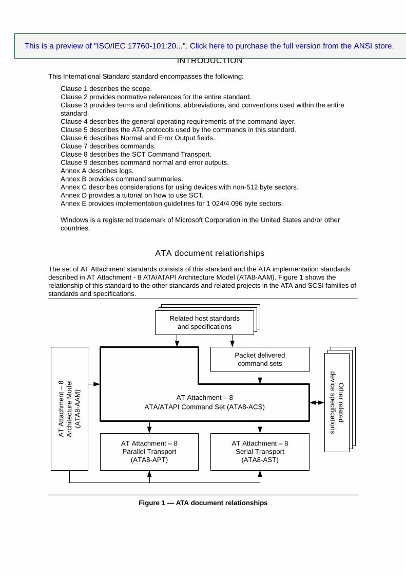
Figure 1 – ATA document relationships............................................................................................. 16Figure 2 – State diagram convention ................................................................................................. 28Figure 3 – Byte, word, DWord and QWord relationships ................................................................... 29Figure 4 – Device Configuration Overlay state diagram .................................................................... 37Figure 5 – HPA Not Set ..................................................................................................................... 42Figure 6 – HPA Set (28)..................................................................................................................... 43Figure 7 – HPA Set (48)..................................................................................................................... 44Figure 8 – HPA Locked (28) .............................................................................................................. 45Figure 9 – HPA Locked (48) .............................................................................................................. 46Figure 10 – LLS and LPS Example.................................................................................................... 59Figure 11 – Alignment 0..................................................................................................................... 59Figure 12 – Alignment 1..................................................................................................................... 59Figure 13 – Alignment 3..................................................................................................................... 59Figure 14 – Power management state diagram................................................................................. 64Figure 15 – Security state diagram .................................................................................................... 73Figure 16 – Selective self-test span example .................................................................................. 255Figure C.1 – Unaligned Write Example............................................................................................ 4 3 3Figure D.1 – Example flowchart for SCT commands....................................................................... 435Figure D.2 – Example sequence for foreground write same with a repeating pattern ..................... 436Figure D.3 – Example sequence for foreground write same with a repeating sector ...................... 436Figure D.4 – Example sequence for writing data using an SCT command with no
background activity ...................................................................................................... 436Figure D.5 – Example sequence for reading data using an SCT command with no background
activity ......................................................................................................................... 437Figure D.6 – Example Sequence for a Non-Data SCT command with no background activity ....... 437Figure D.7 – Example sequence for writing data using an SCT command with background activity ..................................................................................................... 438Figure D.8 – Example sequence for a Non-Data SCT command with background activity ............. 439Figure E.1 – System Dependency Chain......................................................................................... 442Figure E.2 – Mapping Proposals...................................................................................................... 443Figure E.3 – Logical to Physical Mapping........................................................................................ 4 43Figure E.4 – Uncorrectable Error Handling...................................................................................... 445Figure E.5 – Typical HDD Layout Using A Master Boot Record...................................................... 446
This is a preview of "ISO/IEC 17760-101:20...". Click here to purchase the full version from the ANSI store.This is a preview of "ISO/IEC 17760-101:20...". Click here to purchase the full version from the ANSI store.This is a preview of "ISO/IEC 17760-101:20...". Click here to purchase the full version from the ANSI store.This is a preview of "ISO/IEC 17760-101:20...". Click here to purchase the full version from the ANSI store.

– 10 – ISO/IEC 17760-101:2015 © ISO/IEC 2015
TABLES
Table 1 – Numbering conventions examples...................................................................................... 28Table 2 – ATA string byte swapping ................................................................................................... 31Table 3 – ATA firmware revision example .......................................................................................... 31Table 4 – Feature Set Summary......................................................................................................... 32Table 5 – Block Size By Command .................................................................................................... 57Table 6 – Media Card type references................................................................................................ 60Table 7 – Summary of Security States and Characteristics................................................................ 69Table 8 – Security Command Actions................................................................................................. 70Table 9 – IDENTIFY settings for Security state SEC1........................................................................ 74Table 10 – IDENTIFY settings for Security state SEC2...................................................................... 75Table 11 – IDENTIFY settings for Security state SEC4...................................................................... 76Table 12 – IDENTIFY settings for Security state SEC5...................................................................... 77Table 13 – IDENTIFY settings for Security state SEC6...................................................................... 78Table 14 – Preserved Feature Sets and Settings ............................................................................... 80Table 15 – Status field ........................................................................................................................ 87Table 16 – Error field .......................................................................................................................... 89Table 17 – Interrupt Reason Field ...................................................................................................... 90Table 18 – Count field......................................................................................................................... 91Table 19 – Example Inputs ................................................................................................................. 93Table 20 – Example Normal Output.................................................................................................... 93Table 21 – Example Error Output ....................................................................................................... 94Table 22 – Extended error codes........................................................................................................ 96Table 23 – CFA TRANSLATE SECTOR data..................................................................................... 98Table 24 – Device Configuration Overlay Feature field values......................................................... 104Table 25 – Device Configuration Identify data structure ................................................................... 107Table 26 – Device Configuration Overlay (DCO) data structure....................................................... 112Table 27 – Count field output for DOWNLOAD MICROCODE requesting the offset transfer method ....................................................................................................................... 120Table 28 – Diagnostic codes............................................................................................................. 122Table 29 – IDENTIFY DEVICE data ................................................................................................. 126Table 30 – Specific Configuration ..................................................................................................... 143Table 31 – Minor version number ..................................................................................................... 149Table 32 – Normal Erase Mode Time ............................................................................................... 155Table 33 – Enhanced Erase Mode Time .......................................................................................... 155Table 34 – IDENTIFY DEVICE data World Wide Name field (word-based view) ............................. 158Table 35 – IDENTIFY DEVICE data World Wide Name field (byte-based view) .............................. 158Table 36 – Device Nominal Form Factor .......................................................................................... 160Table 37 – Nominal Media Rotation Rate ......................................................................................... 161Table 38 – Transport minor version number..................................................................................... 162Table 39 – IDENTIFY PACKET DEVICE data.................................................................................. 164Table 40 – Standby timer periods ..................................................................................................... 181Table 41 – NV Cache Commands .................................................................................................... 184Table 42 – NV Cache Power Management Commands ................................................................... 184Table 43 – Request Pin Data............................................................................................................ 186Table 44 – Cache Miss Data............................................................................................................. 190Table 45 – Pin Set Data.................................................................................................................... 191Table 46 – Remove Pin Data............................................................................................................ 193Table 47 – NOP Subcommand Code ............................................................................................... 196
This is a preview of "ISO/IEC 17760-101:20...". Click here to purchase the full version from the ANSI store.This is a preview of "ISO/IEC 17760-101:20...". Click here to purchase the full version from the ANSI store.This is a preview of "ISO/IEC 17760-101:20...". Click here to purchase the full version from the ANSI store.This is a preview of "ISO/IEC 17760-101:20...". Click here to purchase the full version from the ANSI store.

ISO/IEC 17760-101:2015 © ISO/IEC 2015 – 11 –
Table 48 – SECURITY DISABLE PASSWORD data content........................................................... 220Table 49 – SECURITY ERASE UNIT data content .......................................................................... 222Table 50 – SECURITY SET PASSWORD data content ................................................................... 225Table 51 – SECURITY UNLOCK data content ................................................................................. 226Table 52 – SET FEATURES Feature field definitions....................................................................... 228Table 53 – Transfer modes............................................................................................................... 231Table 54 – APM levels ...................................................................................................................... 231Table 55 – Write-Read-Verify Modes................................................................................................ 233Table 56 – AAM levels ...................................................................................................................... 234Table 57 – SATA Features ............................................................................................................... 235Table 58 – SET MAX Feature field values........................................................................................ 237Table 59 – SET MAX SET PASSWORD data content ..................................................................... 242Table 60 – SMART Feature field values ........................................................................................... 248Table 61 – SMART EXECUTE OFF-LINE IMMEDIATE Subcommands .......................................... 253Table 62 – Device SMART data structure ........................................................................................ 258Table 63 – Off-line data collection status byte values....................................................................... 259Table 64 – Self-test execution status values .................................................................................... 259Table 65 – Offline Data Collection Capabilities................................................................................. 260Table 66 – TRUSTED RECEIVE Security Protocol field description ................................................ 269Table 67 – Security Protocol 00h - SP Specific field descriptions for Protocol 00h .......................... 270Table 68 – TRUSTED RECEIVE parameter data for SP Specific=0000h ........................................ 270Table 69 – TRUSTED RECEIVE parameter data for SP Specific=0001h ........................................ 271Table 70 – TRUSTED SEND - Security Protocol field description.................................................... 274Table 71 – Fields to issue an SCT command using SMART WRITE LOG....................................... 299Table 72 – Fields to issue an SCT command using WRITE LOG (DMA) EXT................................. 300Table 73 – Successful SCT command response.............................................................................. 301Table 74 – SCT command error response........................................................................................ 302Table 75 – Extended Status codes ................................................................................................... 303Table 76 – SCT data transfer using SMART READ LOG or SMART WRITE LOG.......................... 304Table 77 – SCT data transfer using the GPL feature set.................................................................. 305Table 78 – SCT status request using SMART READ LOG .............................................................. 306Table 79 – SCT status request using the GPL feature set ............................................................... 307Table 80 – Format of SCT status response ...................................................................................... 307Table 81 – SCT command format..................................................................................................... 309Table 82 – SCT Action Codes .......................................................................................................... 309Table 83 – SCT Read/Write Long command .................................................................................... 310Table 84 – SCT Read/Write Long command status response.......................................................... 310Table 85 – SCT Read/Write Long command Format........................................................................ 311Table 86 – SCT Write Same command ............................................................................................ 313Table 87 – SCT Write Same command status response.................................................................. 314Table 88 – SCT Error Recovery Control command .......................................................................... 315Table 89 – SCT Error Recovery Control command status response................................................ 316Table 90 – SCT Feature Control command ...................................................................................... 317Table 91 – Feature Code List ........................................................................................................... 318Table 92 – SCT Feature Control command status response............................................................ 319Table 93 – SCT Data Table command ............................................................................................. 320Table 94 – SCT Data Tables (by Table Identifier) ............................................................................ 320Table 95 – Absolute HDA Temperature............................................................................................ 321Table 96 – SCT Data Table command status response ................................................................... 323Table 97 – Error Bit Defined For Normal Output............................................................................... 324Table 98 – Extended Error Code for Normal Output......................................................................... 325
This is a preview of "ISO/IEC 17760-101:20...". Click here to purchase the full version from the ANSI store.This is a preview of "ISO/IEC 17760-101:20...". Click here to purchase the full version from the ANSI store.This is a preview of "ISO/IEC 17760-101:20...". Click here to purchase the full version from the ANSI store.This is a preview of "ISO/IEC 17760-101:20...". Click here to purchase the full version from the ANSI store.

– 12 – ISO/IEC 17760-101:2015 © ISO/IEC 2015
Table 99 – Generic Normal Output (No LBA Return Value) for Normal Output................................ 326Table 100 – CFA Normal Output ...................................................................................................... 327Table 101 – Media Card Type Normal Output .................................................................................. 328Table 102 – Check Power Mode Normal Output .............................................................................. 329Table 103 – Stream Normal Output .................................................................................................. 330Table 104 – Device Signatures for Normal Output ........................................................................... 331Table 105 – IDLE Unload Normal Output ......................................................................................... 332Table 106 – ATAPI Normal Output ................................................................................................... 333Table 107 – Queued Normal Output................................................................................................. 334Table 108 – HPA Normal Output ...................................................................................................... 335Table 109 – SMART Off-Line Immediate Normal Output ................................................................. 336Table 110 – SMART Return Status Normal Output .......................................................................... 337Table 111 – Generic Extended Normal Output................................................................................. 338Table 112 – SETMAX Extended Normal Output............................................................................... 339Table 113 – Queued Extended Normal Output................................................................................. 340Table 114 – NV Cache Normal Output ............................................................................................. 341Table 115 – NV Cache Flush Normal Output ................................................................................... 342Table 116 – NCQ Command Acceptance Normal Output ................................................................ 343Table 117 – NCQ Normal Outputs.................................................................................................... 343Table 118 – Unsupported Command Error....................................................................................... 344Table 119 – CFA Erase Error ........................................................................................................... 345Table 120 – CFA Write Error ............................................................................................................ 346Table 121 – CFA & Check Power Mode Abort Error ........................................................................ 347Table 122 – Generic Abort wo/ICRC Error ....................................................................................... 348Table 123 – Generic Abort Error....................................................................................................... 349Table 124 – Trusted Abort Error ....................................................................................................... 350Table 125 – Generic SET MAX Error................................................................................................ 351Table 126 – SET MAX Unlock Error ................................................................................................. 352Table 127 – Configure Stream Error................................................................................................. 353Table 128 – Flush Cache Error......................................................................................................... 354Table 129 – Flush Cache Ext Error................................................................................................... 355Table 130 – Read DMA Error ........................................................................................................... 356Table 131 – Read DMA Ext Error ..................................................................................................... 357Table 132 – Read Log Ext Error ....................................................................................................... 358Table 133 – Read PIO Error ............................................................................................................. 359Table 134 – Read Stream Error........................................................................................................ 360Table 135 – HPA Error...................................................................................................................... 361Table 136 – Write Log Error.............................................................................................................. 362Table 137 – Write Log Ext Error ....................................................................................................... 363Table 138 – SMART Error ................................................................................................................ 364Table 139 – Write Extended Error .................................................................................................... 365Table 140 – Write Stream Error ........................................................................................................ 366Table 141 – DCO Set Error............................................................................................................... 367Table 142 – NOP Error ..................................................................................................................... 368Table 143 – PACKET command Error.............................................................................................. 369Table 144 – Read DMA Queued Error.............................................................................................. 370Table 145 – Read DMA Queued Extended Error ............................................................................. 371Table 146 – SMART Read Log/SMART Read Data Error ................................................................ 372Table 147 – Read PIO Extended Error ............................................................................................. 373Table 148 – Read Native Max Extended Error ................................................................................. 374Table 149 – SETMAX Extended Error .............................................................................................. 375
This is a preview of "ISO/IEC 17760-101:20...". Click here to purchase the full version from the ANSI store.This is a preview of "ISO/IEC 17760-101:20...". Click here to purchase the full version from the ANSI store.This is a preview of "ISO/IEC 17760-101:20...". Click here to purchase the full version from the ANSI store.This is a preview of "ISO/IEC 17760-101:20...". Click here to purchase the full version from the ANSI store.
ISO/IEC 17760-101:2015 © ISO/IEC 2015 – 13 –
Table 150 – Write Error..................................................................................................................... 376Table 151 – Write DMA Error............................................................................................................ 377Table 152 – Write DMA Queued Error.............................................................................................. 378Table 153 – NV Cache Add Abort Error............................................................................................ 379Table 154 – NV Cache Remove Abort Error..................................................................................... 380Table 155 – NV Cache Abort Error ................................................................................................... 381Table 156 – NV Cache Abort with Data Transfer Error..................................................................... 382Table 157 – NCQ Command Acceptance Error................................................................................ 383Table 158 – NCQ Write Command Aborted Error ............................................................................ 384Table 159 – NCQ Read Command Aborted Error ............................................................................ 385Table A.1 – Example Log Structure .................................................................................................. 386Table A.2 – Log address definition ................................................................................................... 387Table A.3 – General Purpose Log Directory ..................................................................................... 388Table A.4 – SMART Log Directory.................................................................................................... 388Table A.5 – Comprehensive error log ............................................................................................... 389Table A.6 – General Statistics .......................................................................................................... 390Table A.7 – Extended Comprehensive SMART error log ................................................................. 391Table A.8 – Extended Error log data structure.................................................................................. 392Table A.9 – Command data structure ............................................................................................... 392Table A.10 – Error data structure...................................................................................................... 393Table A.11 – State field values ......................................................................................................... 393Table A.12 – Extended Self-test log data structure .......................................................................... 394Table A.13 – Extended Self-test log descriptor entry........................................................................ 395Table A.14 – NCQ Command Error Log ........................................................................................... 396Table A.15 – Read Stream Error Log ............................................................................................... 397Table A.16 – Stream Error Log Entry................................................................................................ 398Table A.17 – SATA Phy Event Counters Format.............................................................................. 399Table A.18 – Selective self-test log................................................................................................... 400Table A.19 – Selective self-test feature flags.................................................................................... 401Table A.20 – Self-test log data structure........................................................................................... 401Table A.21 – Self-test log descriptor entry........................................................................................ 402Table A.22 – Summary SMART Error log......................................................................................... 403Table A.23 – Error log data structure................................................................................................ 404Table A.24 – Command data structure ............................................................................................. 404Table A.25 – Error data structure...................................................................................................... 405Table A.26 – State field values ......................................................................................................... 405Table A.27 – Write Stream Error Log................................................................................................ 406Table B.1 – Command Matrix ........................................................................................................... 407Table B.2 – Command codes (sorted by command code)................................................................ 408Table B.3 – Command codes (sorted by command name) .............................................................. 412Table B.4 – Historical Command Assignments................................................................................. 415Table B.5 – Historical SET FEATURE Code Assignments............................................................... 423Table D.1 – SCT command using SMART WRITE LOG command ................................................. 440Table D.2 – SCT command using WRITE LOG EXT command....................................................... 440
This is a preview of "ISO/IEC 17760-101:20...". Click here to purchase the full version from the ANSI store.This is a preview of "ISO/IEC 17760-101:20...". Click here to purchase the full version from the ANSI store.This is a preview of "ISO/IEC 17760-101:20...". Click here to purchase the full version from the ANSI store.This is a preview of "ISO/IEC 17760-101:20...". Click here to purchase the full version from the ANSI store.
– 14 – ISO/IEC 17760-101:2015 © ISO/IEC 2015
INFORMATION TECHNOLOGY –
AT ATTACHMENT 8 –
Part 101: ATA/ATAPI Command Set (ACS)
FOREWORD
1) ISO (the International Organization for Standardization) and IEC (the International Electrotechnical Commission)form the specialized system for worldwide standardization. National bodies that are members of ISO or IECparticipate in the development of International Standards through technical committees established by therespective organization to deal with particular fields of technical activity. ISO and IEC technical committeescollaborate in fields of mutual interest. Other international organizations, governmental and non-governmental,in liaison with ISO and IEC, also take part in the work. In the field of information technology, ISO and IEC haveestablished a joint technical committee, ISO/IEC JTC 1.
2) The formal decisions or agreements of IEC and ISO on technical matters express, as nearly as possible, an internationalconsensus of opinion on the relevant subjects since each technical committee has representation from all interested IECand ISO member bodies.
3) IEC, ISO and ISO/IEC publications have the form of recommendations for international use and are accepted byIEC National Committees and ISO member bodies in that sense. While all reasonable efforts are made to ensurethat the technical content of IEC, ISO and ISO/IEC publications is accurate, IEC or ISO cannot be heldresponsible for the way in which they are used or for any misinterpretation by any end user.
4) In order to promote international uniformity, IEC National Committees and ISO member bodies undertake toapply IEC, ISO and ISO/IEC publications transparently to the maximum extent possible in their national andregional publications. Any divergence between any ISO, IEC or ISO/IEC publication and the correspondingnational or regional publication should be clearly indicated in the latter.
5) ISO and IEC do not provide any attestation of conformity. Independent certification bodies provide conformityassessment services and, in some areas, access to IEC marks of conformity. ISO or IEC are not responsible forany services carried out by independent certification bodies.
6) All users should ensure that they have the latest edition of this publication.
7) No liability shall attach to IEC or ISO or its directors, employees, servants or agents including individual expertsand members of their technical committees and IEC National Committees or ISO member bodies for anypersonal injury, property damage or other damage of any nature whatsoever, whether direct or indirect, or forcosts (including legal fees) and expenses arising out of the publication of, use of, or reliance upon, this ISO/IECpublication or any other IEC, ISO or ISO/IEC publications.
8) Attention is drawn to the normative references cited in this publication. Use of the referenced publications is indispensablefor the correct application of this publication.
9) Attention is drawn to the possibility that some of the elements of this ISO/IEC publication may be the subject ofpatent rights. ISO and IEC shall not be held responsible for identifying any or all such patent rights.
International Standard ISO/IEC 17760-101 was prepared by subcommittee 25: Interconnection of information technology equipment, of ISO/IEC joint technical committee 1: Information technology.
The list of all currently available parts of the ISO/IEC 17760 series, under the general title Information technology – ATA attachment 8, can be found on the IEC web site.
This International Standard has been approved by vote of the member bodies, and the voting results may be obtained from the address given on the second title page.
This publication has been drafted in accordance with the ISO/IEC Directives, Part 2, as far as was practicable.
This is a preview of "ISO/IEC 17760-101:20...". Click here to purchase the full version from the ANSI store.This is a preview of "ISO/IEC 17760-101:20...". Click here to purchase the full version from the ANSI store.This is a preview of "ISO/IEC 17760-101:20...". Click here to purchase the full version from the ANSI store.This is a preview of "ISO/IEC 17760-101:20...". Click here to purchase the full version from the ANSI store.

ISO/IEC 17760-101:2015 © ISO/IEC 2015 – 15 –
IMPORTANT – The “colour inside” logo on the cover page of this publication indicates that it contains colours which are considered to be useful for the correct understanding of its contents. Users should therefore print this publication using a colour printer.
This is a preview of "ISO/IEC 17760-101:20...". Click here to purchase the full version from the ANSI store.This is a preview of "ISO/IEC 17760-101:20...". Click here to purchase the full version from the ANSI store.This is a preview of "ISO/IEC 17760-101:20...". Click here to purchase the full version from the ANSI store.This is a preview of "ISO/IEC 17760-101:20...". Click here to purchase the full version from the ANSI store.
– 16 – ISO/IEC 17760-101:2015 © ISO/IEC 2015
INTRODUCTION
This International Standard standard encompasses the following:
Clause 1 describes the scope.Clause 2 provides normative references for the entire standard.Clause 3 provides terms and definitions, abbreviations, and conventions used within the entire standard.Clause 4 describes the general operating requirements of the command layer.Clause 5 describes the ATA protocols used by the commands in this standard.Clause 6 describes Normal and Error Output fields.Clause 7 describes commands.Clause 8 describes the SCT Command Transport.Clause 9 describes command normal and error outputs.Annex A describes logs.Annex B provides command summaries.Annex C describes considerations for using devices with non-512 byte sectors.Annex D provides a tutorial on how to use SCT.Annex E provides implementation guidelines for 1 024/4 096 byte sectors.
Windows is a registered trademark of Microsoft Corporation in the United States and/or other countries.
ATA document relationships
The set of AT Attachment standards consists of this standard and the ATA implementation standards described in AT Attachment - 8 ATA/ATAPI Architecture Model (ATA8-AAM). Figure 1 shows the relationship of this standard to the other standards and related projects in the ATA and SCSI families of standards and specifications.
Figure 1 — ATA document relationships
AT
Atta
chm
ent –
8A
rchi
tect
ure
Mod
el(A
TA8-
AA
M)
Packet deliveredcommand sets
AT Attachment – 8Parallel Transport
(ATA8-APT)
AT Attachment – 8Serial Transport
(ATA8-AST)
AT Attachment – 8ATA/ATAPI Command Set (ATA8-ACS)
Related host standardsand specifications
Other related
device specifications
This is a preview of "ISO/IEC 17760-101:20...". Click here to purchase the full version from the ANSI store.This is a preview of "ISO/IEC 17760-101:20...". Click here to purchase the full version from the ANSI store.This is a preview of "ISO/IEC 17760-101:20...". Click here to purchase the full version from the ANSI store.This is a preview of "ISO/IEC 17760-101:20...". Click here to purchase the full version from the ANSI store.